1
OA090-1.qxp
06.7.20 9:54 AM
Page 1
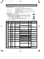
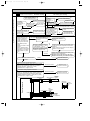
HOME REFRIGERATOR
No. OA090
SERVICE MANUAL
Model
MR-G50J-SS-NZ
CONTENTS
Model name
indication
(Inside a door)
1.
2.
3.
4.
5.
6.
NZ············New Zealand
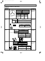
FEATURES ····················································································2
SPECIFICATIONS··········································································3
WIRING DIAGRAM········································································5
OUTLINES AND DIMENSIONS·····················································7
REFRIGERANT CIRCUIT······························································8
TROUBLESHOOTING ···································································9
6-1 FUNCTION OF OPERATION PANEL ···································9
6-2 FLOWCHART OF SELF-CHECK ········································14
6-3 BLOCK DIAGRAM OF PRINTED CIRCUIT BOARD ·········17
6-4 AUTO ICE MAKER ······························································17
6-5 FLOWCHART OF TROUBLE CRITERION·························19
6-6 TROUBLE CRITERION OF MAIN PARTS··························26
6-7 TEST POINT DIAGRAM OF FILTER BOARD ····················31
6-8 TEST POINT DIAGRAM OF CONTROL BOARD···············32
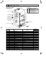
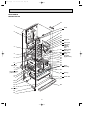
7. NAMES OF THE PARTS ·····························································33
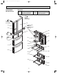
8. DISASSEMBLY INSTRUCTIONS················································34
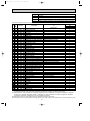
9. RoHS PARTS LIST······································································41
NOTE:
• RoHS compliant products have <G> mark on the spec name plate.
OA090-1.qxp
1
06.7.20 9:54 AM
Page 2
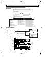
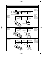
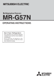
FEATURES
MR-G50J-NZ
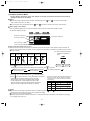
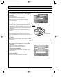
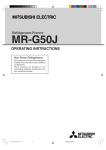
1. Vegetable compartment
(1)Mechanism
Two LED lights are mounted on the back and bottom
of the vegetable compartment. The LED (UV LED)
emits 375nm light, which is the effective wavelength
for biosynthesis of polyphenol. This revolutionary
vegetable compartment stimulates self-defense
function of vegetables and increases polyphenol by
irradiating ultraviolet light to vegetables for a certain
period of time.
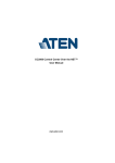
Rate of change in amount of polyphenol
(Cress stored for three days)
About 1.2 times more
polyphenol retained
Amount of polyphenol at the time of purchase
* The lighting of LED is not controlled by opening or closing of the
vegetable compartment door. Thus, the LED may not be lighted
when the door is opened.
(2)Effect
Polyphenol in vegetables increased by 10% compared
to the time of purchase, and the amount of retained
polyphenol was 1.2 times more than that of the
vegetables preserved in prior refrigerators without light
radiation. (See graph)
New vegetable 2002 MITSUBISHI
compartment refrigerator
MR-S46B
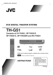
Among different wavelength of light included in sunlight, lights of wavelength that "stimulates
photosynthesis" and "stimulates polyphenol increase" are used in the vegetable compartment.
375nm LED effective for
biosynthesis of polyphenol
590 nm LED effective for
photosynthesis
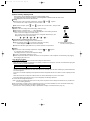
2. " Auto Door Shut" function installed enable doors to be shut easily.
"Auto Door Shut" function automatically closes the door when its opened angle is less than 20 degrees.
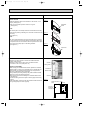
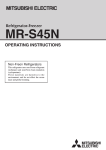
3. Easy Access Vegetable room, Easy Access Freezer Room
The slide rollers enable smooth movement of vegetable
and freezer rooms.
Double rails allow the rooms to be pulled out completely,
providing easy access to even the back of the rooms.
2
▼Slide rollers
OA090-1.qxp
06.7.20 9:54 AM
2
Page 3
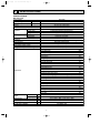
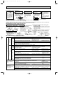
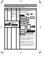
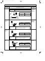
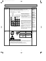
SPECIFICATIONS
SPECIFICATIONS
MR-G50J-NZ
Power supply
V,Hz
Total capacity
L
mm (inches)
Dimensions (H x W x D)
230V,50Hz
492 (R:264 F:82 V:97 I:12 S:37)
1798 x 745 x 699 (70-25/32 x 29-11/32 x 27-17/32)
Acrylic resin coated steel
Cabinet
ABS resin
Food liner
Insulation
Cooling system
Cabinet
Foamed polyurethane (Cyclopentane)
Freezer door
Refrigerator door
Foamed polyurethane (Cyclopentane)
Foamed polyurethane (Cyclopentane)
Freezer
Refrigerator
Forced air convection
Forced air convection
Evaporator
Fin and tube type
Condenser
Cabinet, cabinet ceiling, sides, back and front flange
Defrost system
Automatic heater defrost
Drain
Automatic drainage, Forced evaporation method
Temperature control system
Automatic control
Refrigerator compartment room light
240V,10W (E12)
Accessories
Free pocket (L)
2pcs.
Free pocket (S)
2pcs.
Bottle pocket (S)
1pc.
Bottle pocket (L)
1pc.
Tube stand
1pc.
Height adjustable shelf
1pc.
Three-way flexishelf
1pc.
Two-way flexishelf
1pc.
Small item case
2pcs.
Free egg shelf
2pcs.
Slide chilled case
1pc.
Slide chilled case lid
1pc.
Versa case
1pc.
Aluminum tray (Versa case)
1pc.
Water tank (With light-type bacteria removing filter)
1pc.
Freezing case (upper)
1pc.
Freezing case (lower)
1pc.
Ice server
1pc.
Sound proof mat
1pc.
Ice storage bin
1pc.
Vegetable case
1pc.
Vegetable stand
1pc.
Sliding case (Vegetable case)
1pc.
Drain pan
1pc.
1pc.
Toe grille
Weight
Unit
kg
99
Shipping
kg
110
Capillary tube
mm
{1.6 x {0.63 x 2680 / {1.8 x {0.67 x 2680
Desiccant (molecular sieve)
g
9
Refrigerant filling capacity R600a
g
82
Refrigerating oil (Model)
g
187 (FREOL S10)
3
OA090-1.qxp
06.7.20 9:54 AM
Page 4
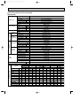
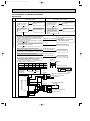
ELECTRICAL PARTS SPECIFICATIONS
MR-G50J-NZ
Model
Power supply
Compressor
ETI100E 13DAH
Rated input
W
230V,50Hz
45/159 (1620/4800rps)
Starting current
A
2.0 (Current limiter)
0.63/2.19 (1620/4800rps)
Running current
A
Winding resistance (A.T.20°C)
9.27"
Model
Motor protector
MM3-71CCV
°C
25
Sec.
16 or less
Ambient temperature
Time
Current
Three-way valve
A
17.0
Model
NSCE001DC1
Defrosting
control
Type
4-phase stepping motor drive voltage DC12V
Control board
Defrosting Model
timer
Specification
Microcomputer
Defrost finish
Thermal fuse
Freezer
compartment Defrost heater
°C
Thermistor 14±1.5
°C
70±2
325" (230V,163W)
Deodorizing function of defrost heater
Not Equipped
Model
UDQM002B3
Type
Refrigerator Input
Fan motor
Revolution
Number of poles
DC brushless motor
2.4 (12V DC)
W
rpm
1520 (12V DC)
10P
Model
Type
Machine
Chamber
UDQM004B3
Input
DC brushless motor
1 (12V DC)
W
rpm
Revolution
1200 (12V DC)
Number of poles
Water pipe heater
10P
230V-8.0W
Rotational heater board
230V-8.0W
Heater
Divider heater (I/S)
230V-5.5W
(Rating)
Vegetable compartment heater 1
230V-9.0W
Vegetable compartment heater 2
230V-9.0W
220V-10.0W
Ice making tray heater
°C
Ice maker temperature
Model
Freezer
-11.6
NTC thermistor
Versa
Slide chilled
Refrigerator
Compressor
Temperature control
Dial position
ON
OFF
-24.1
-0.6
HI
:
-20.3
MID
:
-17.6
-21.4
LOW
:
-14.9
-18.7
REFRIGERATOR
:
–
CHILLED
Ice making
Motor damper
Vegetable
Heater
OPEN SHUT OPEN SHUT OPEN SHUT OPEN SHUT
ON
OFF
-1.8
–
–
–
–
–
–
2.3
3.5
1.6
0.4
–
–
–
–
–
–
3.2
4.5
4.8
3.5
–
–
–
–
–
–
4.2
5.4
–
–
–
4.4
2.4
–
–
1.2
-0.1
–
–
:
–
–
–
–
1.8
-0.1
-1.0
-2.3
–
–
–
–
LOW (Soft freezing)
:
–
–
–
–
-2.3
-4.0
–
–
–
–
–
–
MID (Soft freezing)
:
–
–
–
–
-4.0
-5.9
–
–
–
–
–
–
HI (Soft freezing)
:
–
–
–
–
-5.9
-7.7
–
–
–
–
–
–
FREEZER
:
–
–
–
–
-17.1
-20.4
–
–
–
–
–
–
ICE MAKING
:
–
–
–
–
–
–
–
–
-20.2
-23.1
–
–
ICE MAKING STOP
:
–
–
–
–
–
–
–
–
-20.2
-23.1
–
–
CRYSTAL ICE MAKING
:
–
–
–
–
–
–
–
–
-20.2
-23.1
–
–
4
WHITE
WHITE
WHITE
WHITE
YELLOW
BROWN
I.THERMISTOR
WHITE
BRIGHT
YELLOW
V.THERMISTOR
VERSA.THERMISTOR
WHITE
DEF.THERMISTOR
WHITE
WHITE
WHITE
ORANGE
YELLOW
GREEN
BLUE
SKY BLUE
LIGHT BROWN
YELLOW GREEN
BLACK
VIOLET
BLACK
WHITE
VIOLET
WHITE
RED
LED
WHITE
RED VIOLET
FAN MOTOR (FOR COMPRESSOR)
FAN MOTOR
Vegetable compartment LED board
WATER PUMP
DOOR SWITCH.(FOR R-COMPARTMENT & ICE MAKING COMPARTMENT)
YELLOW
BRIGHT YELLOW
ORANGE
BLACK
LIGHT GREEN
BLACK
GRAY
RED
RED
GRAY
GRAY
GRAY
W WHEN THE DOORS ARE CLOSED.
PINK
WHITE
ICE-TRAY THERMISTOR LIGHT
WHITE GREEN
F.THERMISTOR
WHITE
WHITE
WHITE
INVERTER
C.THERMISTOR
R.THERMISTOR
SKY BLUE
WHITE / RED
F1
:10A FUSE
FUSE1 : 3A FUSE
ON THE BOARD
CONTROL BOARD, N/F BOARD
WHITE
WHITE
RED
YELLOW
LIGHT GREEN
WHITE
RED
GRAY
GRAY
RED
GRAY
DIVIDER HEATER (I/S)
WHITE
GRAY
VIOLET
GRAY
ORANGE
ROTATIONAL HEATER BOARD
DEFROST HEATER
WHITE
RED
WATER PIPE HEATER
RED
RED
Vegetable compartment heater 1
Vegetable compartment heater 2
ICE MAKING TRAY HEATER
R-COMPARTMENT ROOM LIGHT
WHITE
BLUE
RED
THERMAL FUSE (73:)
WHITE
GRAY
WHITE
RED
WHITE
YELLOW
GREEN
YELLOW
YELLOW
MOTOR PROTECTOR
5
WHITE
BLUE
BROWN
WHITE / RED
PINK
RED
GRAY
YELLOW
COMPRESSOR
I.THERMISTOR (Ice making compartment thermistor)
V.THERMISTOR (Vegetable compartment thermistor)
VERSA.THERMISTOR (Versa compartment thermistor)
DEF.THERMISTOR (Defrost thermistor)
ICE-TRAY THERMISTOR (Ice making tray thermistor)
F.THERMISTOR (Freezer compartment thermistor)
C.THERMISTOR (Slide chilled compartment thermistor)
R.THERMISTOR (Refrigerator compartment thermistor)
RED
BLUE
LIGHT BROWN
WHITE
RED
ICE GEAR BOX
MOTOR DAMPER
MOTOR DAMPER
TEMP. CONTROL BOARD
(LIQUID CRYSTAL DISPLAY) MOTOR DAMPER
YELLOW
YELLOW
YELLOW GREEN
SKY BLUE
GRAY
BLACK
PINK
WHITE
RED
BROWN
THREE-WAY
VALVE
WHITE
BLUE
SKY BLUE
VIOLET
RED
WHITE
V
BLUE
YELLOW
BLACK
BLACK
PLUG
W
U
VIOLET
ORANGE
BLUE
YELLOW
N
L
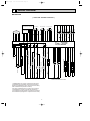
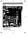
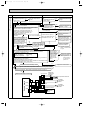
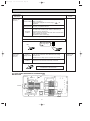
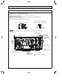
WIRING DIAGRAM
3
Page 5
06.7.20 9:54 AM
OA090-1.qxp
MR-G50J-NZ
( SKELTON WIRING DIAGRAM )
OA090-1.qxp
06.7.20 9:54 AM
Page 6
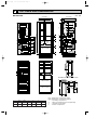
MR-G50J-NZ
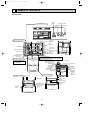
( ACTUAL WIRING DIAGRAM )
FUSE1
1 2
CONTROL BOARD
8
CN7S
141110 9 8 7 6 5 4 3 2 1
CN8K
765 4 21
CN3A
11 9 7 5 3 1
7
CN2A
5 31
CN50G
531
CN1
3 1
Black
White
Red
Gray
Yellow
Red
Gray
Yellow
Blue
White
Yellow green
Black
Light brown
Blue
Brown
Yellow
Bright yellow
Yellow green
Pink
Light green
Orange
Sky blue
Gray
Pink
Black
Blue
Yellow green
White
Red
Black
Black
Light green
Bright yellow
Violet
Orange
Yellow
Blue
White
Red / White
Red
Brown
Yellow green
Light green
Pink
Brown
White
Red / White
Red
Yellow
Blue
Orange
Black
Light green
Violet
Gray
White
Refrigerator
Compartment
N
Blue
Red
White
Yellow
4
3
2
1
Blue
Red
White
White
Yellow
White
MOTOR DAMPER
1
2
3
4
5
6
Blue
Red
Yellow green
White
Red / White
Sky blue
N
Yellow
Orange
White
White
R. THERMISTOR
White
Red
Sky blue
Blue
Light green
Sky blue
White
White
1
2
3
4
Yellow
Gray
Orange
Sky blue
1
2
3
4
5
6
7
8
White
Red
Sky blue
Blue
Light green
Sky blue
Light brown
Sky blue
Yellow green
Red
Light green
Gray
Blue
Violet
White
Yellow
Red
Gray
Gray
2
Sky blue
Brown
White
White
1
1 2 3 4 5 6 7 8 9
6 54 3 2 1
White
Red
Black
White
White
Red
Sky blue
Brown
White
Yellow
Gray
Gray
Gray
4 3 2 1
Violet
Violet
Light green Light green
Orange
Orange
Black
Black
S.THERMISTOR
Violet
Light green
Orange
Black
1 2 3 4 5 6
Red
Red
Bright yellow
Pink
Yellow
Violet
ICE-TRAY DIVIDER HEATER MOTOR
DAMPER
HEATER (I/S)
1 2 3 4 5 6
Blue
Red
White
Yellow
White
4
3
2
1
Yellow
White
White
Red
Blue
ICE-TRAY
THERMISTOR
1 2
Red
Red
White
White
White
White
Gray
White
White
White
Blue
Yellow
Red
White
I.THERMISTOR
Ice
compartment
Versa
Compartment
1 2
Yellow green
Gray
Bright yellow
Black
Yellow
Violet
3 4
Bright yellow
Red / white
White
Sky blue
Red
Brown
1 2
Gray
White
White
Brown
1 2 3 4 5 6
Yellow
Gray
Gray
Sky blue
WATER PIPE
HEATER
Sky blue
Light green
Blue
Sky blue
Red
White
Ice compartment / versa compartment door
DOOR SWITCH
(FOR R-COMPARTMENT
& ICE COMPARTMENT)
WATER PUMP
LED
ICE-GEAR BOX
Vegetable
compartment
heater 1
1
Black
2
Violet
1
2
White
White
Gray
Yellow green
Freezer compartment door
VEGETABLE
COMPARTMENT
HEATER 2
DEFROST HEATER
F.THERMISTOR
THERMAL
FUSE (73:)
White
White
1
Red
I.THERMISTOR (Ice making compartment thermistor)
V.THERMISTOR (Vegetable compartment thermistor)
S.THERMISTOR (Versa compartment thermistor)
DEF.THERMISTOR (Defrost thermistor)
ICE-TRAY THERMISTOR (Ice making tray thermistor)
F.THERMISTOR (Freezer compartment thermistor)
C.THERMISTOR (Slide chilled compartment thermistor)
R.THERMISTOR (Refrigerator compartment thermistor)
( When the doors are closed. )
6
1 2 34 5
Three-way
valve
Machine
chamber
compartment
Yellow
1
2
Violet
Red
Blue
MOTOR DAMPER
1 2 3 4 56
DEF.THERMISTOR
Black
Orange
Violet
Yellow
Blue
Blue
Red
White
Yellow
Pink
V. THERMISTOR
Yellow
Violet
Black
White
Red
Vegetable compartment
LED board
White
Yellow
White
White
Red
Blue
4
3
2
1
Machine
chamber
fan motor
Sky blue
1 2 3 4 5 6
2 3 4
1
Violet
Black
White
White
FAN MOTOR
1 2 3 4
Violet
Gray
Black
White
Red
Sky blue
Light brown
Yellow green
Blue
Pink
Brown
4 3 2 1
Violet
Black
Sky blue
Yellow
Pink
Bright yellow
Yellow
Violet
Vegetable compartment door
Vegetable
compartment
Freezer
Compartment
L
L
Power
Plug
AC230V
50Hz
Slide
Compartment C. THERMISTOR
R-COMPARTMENT
ROOM LIGHT
Brown
654321
F1
Blue
CN4D
16151413121110 9 8 7
X1SSR1
Violet
CN9D
12 1110 9 8 7 6 5 4 3 2 1
CN12
3 1
INVERTER
SSR5 SSR4 SSR3 SSR2
Gray
Gray Gray
White White
Electric
box
2 1
Gray
Pink
black
Sky blue
Refrigerator compartment door
1 2 3 4
N/F BOARD
Red
Red
Gray
Red
Black
Sky blue
Rotational heater board
TEMP. CONTROL
BOARD
1
2
3
4
3
2 1
MOTOR
PROTECTOR
COMPRESSOR
(View from rear
left side)
06.7.20 9:54 AM
4
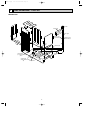
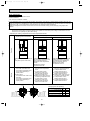
Page 7
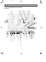
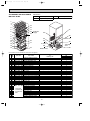
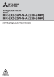
OUTLINES AND DIMENSIONS
MR-G50J-NZ
Unit : mm
699 (Display)
745 (Display)
72
10
10
607
123
740 (Cabinet)
5
284
456
124
324
313
124 124
782
720
324
318
12
275
52
142
41 176
214
8
337
77
400
1798 (Display)
249
162
249
284
101
37
8
456
312
5
284
361
440
363
332
99
262
168
7
361
392
351
307
329
534
600
669(Pitch between the rear wheels)
691(Pitch between the adjust bolts)
727(Pitch between the front wheels)
67
654
654
2500
642
203
374
203
162
655
76 76
367
196
REQUIRED SPACE FOR INSTALLATION
100
610
745
20
20
930
1100
612
601
1809
OA090-1.qxp
607
247
338
699
R(L)
R(R)
I
S
V
F
H
782
782
214
214
361
361
W
284
456
284
456
745
745
R(L) : Refrigerator compartment (Left)
R(R) : Refrigerator compartment (Right)
I
: Ice making compartment
S
: Select compartment [Versa compartment]
V
: Vegetable compartment
F
: Freezer compartment
7
OA090-1.qxp
5
06.7.20 9:54 AM
Page 8
REFRIGERANT CIRCUIT
MR-G50J-NZ
Muffler
Evaporator
Suction pipe
Capillary tube
{1.8✕{0.63✕2680(mm)
Dryer
#150
Cabinet pipe
Three-way
valve
Charge pipe
(Low pressure side)
{6.35
Charge pipe
(High pressure side)
{4
Compressor
Radiator
plate
8
Capillary tube
{1.6✕{0.67✕2680(mm)
OA090-1.qxp
06.7.20 9:54 AM
6
Page 9
TROUBLESHOOTING
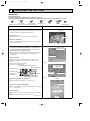
6-1 FUNCTION OF OPERATION PANEL
MR-G50J-NZ
(1) Function of normal operation
REF VEG L D
REF
Min CHILL
: SOFTF
VR
M
QCK QCK ICE L M H
VEG
REG ICE F Z R H
FZR ECO CRL ICE ICE(STOP) DEO
SELECTION switch
MODE switch
●The switch functions to set the
operation mode or temperature
of compartments individually.
●The switch functions to
select the required
compartment.
Press
switch and display the
required compartment to apply the
function of temperature adjustment
or quick mode.
When setting the operation mode
of refrigerator, vegetable, and
freezer compartment to "Middle" at
the same time.
QUICK MODE switch
●Each compartment can
be cooled rapidly.
Quick mode is finished
automatically.
ECO MODE switch
●Each compartment
can be operated with
energy saved.
It automatically
finishes about 2 hours later.
Press
switch for about 3 seconds
until a "beep" sound is heard.
When stopping
quick mode halfway
Convenient function
Cooking timer
Press
1
Press
switch and
switch for 1 second at the same time. (
(Cooking timer can be released in the same way.)
Cooking timer mode is set and "0" blinks.
switch. ➝ Press
Set the time with
(1~99 minutes)
is displayed.)
to start ➝ Alarm sound will annonce the
completion of cooking period.
(To stop the timer halfway through the operation, press
again).
Child lock
2
Press
switch for 3 seconds at the same time.
( is displayed.)
(Child lock can be released in the same way.)
Press
ICE(STOP)
with
to select "vegetable compartment".
Press
for 3 seconds. The setting of the refrigerator
compartment, vegetable compartment, and
the freezer compartment will be set to "Middle",
and fast cooling operation, energy-saving
operation, and cooking timer setting for all
compartments will be canceled.
switch.
ON/OFF of LED for bacteria removal from water tank
4
w
Press
switch for about
3 seconds against one of the
compartments which is in
QUICK MODE.
To use "ice making compartment" as "refrigerator
compartment"
to select "ice making compartment".
➝ Select
When stopping
quick mode of all
compartments at once
w To reset the unit to the initial setting, press
switch and
Ice making stop
3
switch again.
switch and
switch for 3 seconds at the same time.
(
is displayed.)
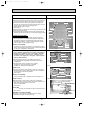
Operating mode and Temperature range
Mode
Compartment
Refrigeratorcompartment Middle
Refrigerator
Chilled
Versa
compartment
Soft freezing (Middle)
Freezer
Refrigerator
Ice making
Ice making
compartment
Ice making stop
Vegetable compartment Middle
Freezer compartment Middle
Temp range
Approx. 0 to 6:
Approx. 0 to 6:
Approx. -2 to 2:
Approx. -9 to -5:
Approx. -18 to -16:
Approx. 0 to 6:
Approx. -21 to -17:
Approx. -21 to -17:
Approx. 3 to 9:
Approx. -21 to -17:
1Press
to select "ice making compartment."
2Press
for about 3 seconds and let
REF
flash.
3After ice-making compartment is set to function as refrigerator,
take ice or water out of the ice tray which are automatically
dropped into ice storage bin. When ice-making function
will not be used for a while, wash the water tank well with
water and place it back after drying thoroughly.
4To get back to "ice making", just change the temperature
setting.
wThe temp range above is based on the data measured at the center of each
compartment with the door closed and with no food inside under the condition of
ambient temperature 30:. The range varies depending on circumstances.
9
OA090-1.qxp
06.7.20 9:54 AM
Page 10
(2) Demonstration mode for shop display
Demonstration mode is not available when the temperature of freezer compartment is -7: or less even if
and
,
are simultaneously pressed for about 5 seconds and a “beep” sound is heard. Cooling operation starts
instead.
1 Setting
●Within one minute after power supply is turned on, simultaneously press
,
, and
switch for about
5 seconds with the door of ice making compartment left open. When the setting is complete, a “beep” sound is heard
and “D” is displayed.
2 Panel operation mode during demonstration mode
The panel operation mode changes to “manual” if any of the switches is pressed and it changes to “auto” if none of the
switches is pressed within 3 minutes after demonstration mode is set.
Manual mode: Panel indication changes according to switch operation.
Auto mode: Panel indication is automatically changed.
3 Release
●Simultaneously press
,
and
switch for about 5 seconds with the door of ice making compartment left open.
When the function is released, a “beep” sound is heard. “D” disappears and the panel indication gets back to normal.
Note: Follow the procedure above to release demonstration mode as it cannot be released by simply turning
on/off the power supply.
(3) Fine adjustment of temperature
Fine adjustment of temperature is available for refrigerator compartment, freezer compartment and versa
compartment.
As for versa compartment, however, it is only available when the compartment is set to R E F or F Z R .
1 Setting
●Press
switch to select refrigerator compartment, freezer compartment or versa compartment.
●Simultaneously press
and
for about 3 seconds until a “beep” sound is heard.
L
M
●The indication changes as show in the right.
H
2 Fine adjustments of temperature
Temperature adjustment is made by approximately 0.3-0.5: by pressing
and it is indicated with 15-steps bars
on the panel. The temperature displayed on the panel, however, changes by 1: and might not change according to
fine adjustment.
L
L
L
Example of display:
M
M
M
H
H
H
In case of versa compartment
●Press
to make versa compartment function as refrigerator or freezer .
When the blinking marks on the display,
REF
or
FZR
, are lit in 3 seconds, apply fine adjustment of temperature.
3 Release
Follow the same procedure as setting and the finely-adjusted temperatures are reset for refrigerator compartment, freezer
compartment and versa compartment at once.
(4) Ice making test / Self-check
This function is not available during the following modes: Child lock, Demonstration, Cooking timer, Changing the
rotational speed of compressor, and Error code display.
1 Setting
●Press
for about five seconds.
2 Operation and its display
●While automatic ice making is testing, the indication of ice making compartment setting blinks on LCD.
●When something is faulty, the error code is indicated.
3 Release
The test automatically finishes in 10 minutes and the error code changes to temperature display.
(5) Thermistor temperature check mode
1 Setting
●With the door of ice making compartment left open, simultaneously press
“beep” sound is heard and “88” blinks.
●Press
with the door left open.
10
and
for about 3 seconds until a
OA090-1.qxp
06.7.20 9:54 AM
Page 11
2 Display
After the setting is complete, the kinds of thermistor and its temperature are alternately shown on the panel.
In case of abnormality, the display returns to current temperature. Please note that the temperature detected
by thermistor may be a little different from the real one due to the influence of refrigerator temperature.
Kind of
thermistor
Defrosting
Versa
Refrigerator Slide chilled Ice making
Ice making
compartment compartment compartment compartment
tray
Vegetable
Freezer
Outside air
compartment compartment
Display
(d)
(R)
(C)
(K)
(S)
Refrigerator compartment
Ice making compartment
Vegetable compartment
(V)
(F)
(O)
(Ex.) When defrost
thermistor
. A short beep sound is heard at each press
reads -28:.
3 Change of display
●While thermistor temperature check mode is set, press
and the thermistor is changed in the order below.
Defrosting
(I)
TEMP
Slide chilled compartment
Versa compartment
Ice making tray
Freezer compartment
Outside air
d
W The defrosting thermistor is always selected first at the beginning of the setting.
4 Release
●With the door of ice making compartment left open, simultaneously press
and
for about 3 seconds until a beep sound is heard. The temperature of thermistor disappears
and the display gets back to current temperature.
●The function is automatically released one-hour later.
●Follow the procedure above to release this mode. For the prevention of the compressor, avoid releasing
it by plugging and unplugging the power cord.
TEMP
-28
(6) Change mode of compressor rotational speed
Operation sound can be checked by changing the rotational speed of compressor. Always conduct a check while the
compressor is operating and the “-” mark is not on the display, which shows the compressor stops. If the “-” mark is on the
display, unplug the power cord and then plug it in a few seconds to operate the compressor. Also, this function is not
available during the following modes: Child lock, Demonstration, Cooking timer, Thermistor temperature check and error
code display.
(Ex.) When the rotational
1 Setting
speed is 52 rps
●With the door of ice making compartment left open, simultaneously press
and
TEMP
for about 3 seconds until a “beep” sound is heard, and “88” blinks.
●Press
52
with the door left open.
2 Changing the rotational speed
●After the setting is complete, press
and the rotational speed of compressor alternately changes in 6 steps.
The rotational speed (rps) is shown on the panel. Basically the compressor starts operating at level 5, however, it depends
on model or specification change.
Normal
Level 0
Level 1
Level 2
Level 3
Level 4
Level 5
High speed
Low speed
W Note: Operation sound may get increased in the process of changing the speed, but that does not mean any
problem. Check the operation sound when the rotation is stabilized.
3 ON and OFF of machine chamber fan motor
Under this function, fan motor in machine chamber can be switched on and off at each press of
The on/off state is shown with
mark on the panel.
Machine chamber fan motor
Display of
ON
Displayed
OFF
Not displayed
switch.
4 Release
●With the door of ice making compartment left open, simultaneously press
and
for about 3 seconds until a
“beep” sound is heard. The screen returns to the temperature display.
●The function is automatically released one-hour later.
●Follow the procedure above to release this function. For the prevention of the compressor, avoid releasing it by plugging
and unplugging the power cord.
11
OA090-1.qxp
06.7.20 9:55 AM
Page 12
(7) Damper Operation Mode
During damper operation mode, the damper is forcibly opened and closed and the state of
damper is shown on the panel.
1 Setting
●With the ice making compartment door left open, simultaneously press
“beep” sound is heard, and “88” blinks.
●With the door left open, simultaneously press
and
and
for about 3 seconds until a
for about 3 seconds until a “beep” sound is heard.
2 Status display of each damper
Each compartment display turns on when each damper is open and turns off when each damper is closed.
Ex.) When all dampers are open;
Refrigerator compartment
Ice making compartment
Slide chilled compartment
REF
CHILL
VR
Versa compartment
FZR
Freezer compartment
3 How to make each damper open or close
Although the state is shown on the panel, check airflow and confirm the damper is really opened or closed. However, air
does not come out when the door is closed, so put a magnet on the door switch to simulate the condition of the door closed.
●Change of display
Kind of
damper
(Ex.) When making the damper of
refrigerator compartment
open
Refrigerator Slide chilled Ice making
Versa
Freezer
compartment compartment compartment compartment compartment
TEMP
Display
(R)
(C)
(I)
(S)
(F)
(1)Press
to select the damper to be set up.
A “beep” sound is heard and the kind of damper is changed every time
Refrigerator compartment
Versa compartment
(2)Press
Slide chilled compartment
(1)Damper to
be set up
(2)" 0 " to open,
" " to close
is pressed.
Ice making compartment
Freezer compartment
to “0” to open the damper or “
” to close the damper.
(3)Press
for about 3 seconds to convey the setting to the damper.
A“beep”sound is heard if the setting has been conveyed.
After the setting is conveyed, the damper starts operating
and the display blinks. It stops blinking and starts to light
when the operation stops automatically. Please note that the
setting cannot be changed when the damper is operating.
As the damper of slide chilled compartment opens and
closes in conjunction with the damper of refrigerator
compartment, it is necessary to set them to the either
of the following.
How to set
to 0.
Open
Open Set
Close
Open Not available
Open
Close Set
to 0 and then set to .
Close
Close Set
to .
to 0 and then set
4 Release
●With the door of ice making compartment left open, simultaneously press
and
for about 3 seconds until a
“beep” sound is heard. The screen returns to the temperature display.
●This function is not automatically released.
●Follow the procedure above to release this function. For the prevention of the compressor, avoid releasing it by plugging
and unplugging the power cord.
12
OA090-1.qxp
06.7.20 9:55 AM
Page 13
(8) Error history display mode
Error history can be observed in the error history display mode.
Use this mode when the actual problem of the refrigerator is different from the error which
was displayed at the service-call received.
1 Setting
●Open the door of the ice making compartment, and press
for 3 seconds until a “beep” is heard and and “88” blinks.
●With the door left open, press
and
and
together
together for 3 seconds until a “beep” is heard.
2 Display details
●Same as the error display and trouble locating. (Refer to 6.2(3))
●When there is no recorded error, “ — ” will be displayed.
●When several errors have occurred, error will be displayed in the increasing numerical
order, as in the error display and trouble locating.
(Ex.) In case errors in the ice tray thermistor (e10), refrigerator thermistor (e13) and
refrigerator fan motor (e31) have occurred:
e ➝ 10 ➝ 13 ➝ 31 ➝ e ➝ 10 ➝ 13 ➝ 31 ·····
3 Check points and resetting the error history
●Follow the treatment procedures shown in the self-check.
●After the treatment, press
for 3 seconds to reset the error history.
“ — ” will be displayed when the data is reset successfully.
●Perform the self-check again (Refer to 6.2) to confirm there are no dysfunctions.
(Ex.) When there is problem
with the ice maker gear box.
4 Release
●Open the door of the ice making compartment, and press
and
together
for 3 seconds until a “beep” is heard.
The display will return to the normal temperature display.
●Function is automatically released in an hour.
●Follow the procedure above to release this function. For the prevention of the compressor, avoid releasing it by plugging
and unplugging the power cord.
Door Buzzer System :
Door buzzer has been installed so that one will not forget to close the door.
When the door of refrigerator compartment or ice making compartment is left open for a minute, the buzzer starts ringing and
informs that the door needs to be closed.
When door is left open for:
Buzzer
1 minute- 4 minutes
Buzzer rings every 1 minute
More than 5 minutes
Keeps ringing
The buzzer will stop ringing as soon as the door is closed.
However, this buzzer system does not work when the door is not widely open like when something is pinched between the
door and refrigerator.
If the door is not closed completely, the temperature inside the refrigerator will rise and it will be a cause of spoiling the food
inside.
When the buzzer does not stop even if all the doors are closed, abnormality may occur in door switch.
If the buzzer keeps ringing and annoying, it can be stopped by the following operations.
1 Perform the ice making test operation.
(Note: If the test is conducted with water in the ice tray, water may fall into the ice storage bin because the tray is rolled over
in the ice making operation.)
Buzzer sounds when a trouble is found in refrigerator fan motor or in machine chamber fan motor. The buzzer sounds every
time the door is closed until the fan motor gets to operate correctly.
(Check the error code by following the steps in Specification of display in self-check result on page 14.)
13
OA090-1.qxp
06.7.20 9:55 AM
Page 14
6-2 FLOWCHART OF SELF-CHECK
MR-G50J-NZ
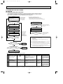
(1) Troubleshooting with self-check
This refrigerator has self-check feature to clarify and indicate where & what the trouble is.
You can perform operation checks and identify malfunction of electric or electronic parts.
Error history is recorded and can be displayed by the refrigerator.
A
Self-check
Operate the ice-making test.
(Current displayed error: Refer to 1
in the table below.)
The display of ice making compartment setting will blink during the test.
During the ice-making
test mode, watch the
operation ice-maker
gear box and water
pump in refrigerator.
D Error history mode (Refer to 6.1(8))
Problem may recover automatically.
Perform the following if error is not displayed
before treatment or the error which was displayed
at the time power of the unit was turned on is not displayed.
No
Is error displayed?
Set the error display mode.
Yes
B
No
Locate the trouble according to LED
indication. (See page 15,16)
Is error displayed?
Release error displayed
mode, and the self-check
is finished.
Yes
c
Unplug the power cord from outlet.
Perform self-check
procedures B through C.
Repair /replace defective part(s)
according to LCD indication.
Reset the error history.
(Refer to 6.1(8))
*Wait 10 minutes
before inserting
the cord once
it's unplugged.
(if the cord is
plugged in within
10 minutes, error
may be displayed.)
Self-check
Plug the power cord into outlet.
(Current displayed error:
Refer to 2 in the table below.)
Yes
Yes
Is error displayed?
No Release error display
mode and perform the
self-check again.
(go to A)
Note1: Self-check cannot detect abnormalities in the following parts.
See page 19-31 for troubleshooting.
Door switch
Motor damper
Heater (Water pipe / Vegetable compartment heater, etc.)
Water pump motor
Is error displayed?
No
No
Was more than one error
displayed during repair?
Note2: If any abnormality is found when switch is turned on, compressor
and fan motor are suspended for 10 minutes.
D
Perform error
history mode.
Note3: The alarm beeps when some abnormalities (motor-locked) have
occurred at the refrigerator fan motor restarts its normal operation.
Note4: If any abnormality occurs in compressor's inverter circuit,
the compressor and the refrigerator fan motor stop for 10 minutes
(not only when plugging the power cord).
Yes
Was the error which was
displayed at the service-call received
was turned on displayed?
Was treatment performed?
D
No
Perform error
history mode.
Yes
Self-check is finished.
●Self-check and error display method and operation
Item
(current displayed error)
Self-check
Display error
history.
1Ice making test operation.
Press the
switch.
All items except (*6) listed
for 5 seconds.
up on the table at page
17 will be checked.
Operation method
Display or self-check operation
1.Conduct the automatic ice making test.
(The display of ice making compartment
setting is blinked)
2.When trouble is found, all error codes
except e50-e55 are displayed.
3.When error is not found, nothing is
displayed.
Display time
2Power input.
All items except (*6) listed
up on the table at page
17 will be checked.
Plug the power
cord into outlet.
1.When trouble is found, all trouble except
e50-e55 and displayed.
2.When error is not found, nothing is
displayed.
For 10 minutes
after power is
supplied.
3Error history
Refer to 6.2(3)
Error history
display mode.
1.When trouble is found, all trouble except
e50-e55 and displayed.
2.When error is not found, nothing is
displayed.
For one hour
after setting,
or until mode
is released.
For 10 minutes
after setting.
●Release of self-check display mode
self-check finishes automatically. Error cord display is automatically released 10 minutes later.
14
Others
Self-check is not available
during child lock, cooking
timer, changing the rotational speed of compressor,
checking the temperature
of thermistor, damper operation and demonstration
modes.
Self-check is not available
during demonstration
mode.
Self-check is not available
during child lock, cooking
timer, changing the rotational speed of compressor,
checking the temperature
of thermistor, damper operation and demonstration
modes.
OA090-1.qxp
06.7.20 9:55 AM
Page 15
(2) Timing in self-check
Trouble of Defrost heater
: Self-check is conducted after defrosting.
(Make sure to confirm the display before unplugging the power cord
because it is automatically reset once the power cord is pulled out.)
Trouble of Ice maker
: Press the
switch on the panel for 5 seconds. (Ice making test mode.)
The setting of ice making compartment blinks on LCD during the test operation.
: Open the door and then closed it.
When abnormality is found in fan motor, buzzer sound is heard every time the door
is closed.
: Check the error when compressor starts up or is operating.
: Self-check is continuously working
TEMP
Trouble of Fan motor
Trouble of Inverter
Trouble of Thermistor
(3) Error display and trouble locating
1. Display details
After conducting the self-check by referring to 6-2(1), error codes are displayed in the temperature display section. ”e” and two digit error code flashes alternately as shown in the right figure.
When several errors occur, they are displayed alternately. However, the error whose code has
a smaller number has priority to be displayed first.
(Ex.) In case the errors of ice tray thermistor (e10), refrigerator thermistor (e13) and refrigerator
fan motor (e31) are happening simultaneously;
e
TEMP
e ➝ 10 ➝ 13 ➝ 31 ➝ e ➝ 10 ➝ 13 ➝ 31 ·····
✻ For 2 minutes in self-check, a high-tone sound is heard due to the operation check of damper.
2. Check point and treatment
Display
Error code
Trouble
(*1)
Testing
e
33
(Ex.) When ice maker gear
box is defective.
Detecting method
(*3)
Check point
Treatment
Control
Ice maker is under testing
01
When the following communi- 1. Connector CN8K, CN7S on control board Repair the
(*5)
Keep the same operation as
Communication cation errors occur
4-pin relay connector (hinge)
contact failure. the one before the communibetween control board and
error of
4-pin connector on operation P.C. board
cation error has occurred.
operation P.C. board:
operation panel •They transmit and receive
data that has nothing to do
with settings.
2. Trouble of control board and operation
Replace
•They cannot transmit and
P.C. board
LCD
Self-check
receive data each other
for about two seconds.
e
02
e
03
e
10
e
11
e
12
e
13
e
14
e
15
e
16
Communication When abnormality is found in
error of inverter the communication between
refrigerator control circuit and
inverter control circuit in control board. (When they do not
transmit and receive data for
10 seconds.)
When the model of con- 1. Check the model name of control board
Trouble of
model judge- trol board is different from
the one of operation P.C. 2. Check the operation p.c. board.
ment
board.
Trouble of ice When there is a short or 1. Connector CN7S on control board, Ice gear
open circuit in the ice
box 6-pin relay connector, 8-pin relay
making tray
making tray thermistor.
connector
thermistor
2. Check the resistance of thermistor.
Replace the Compressor OFF.
control
board.
When there is a short or 1. Connector CN7S on control board. 6-pin
open circuit in the freezer
relay connector
compartment thermistor.
2. Check the resistance of thermistor.
When there is a short or 1. Connector CN7S on control board. 2-pin
relay connector
open circuit in the defrost
thermistor.
2. Check the resistance of thermistor.
When there is a short or 1. Connector CN7S on control board, 4-pin
Trouble of
open circuit in the refrigrefrigerator
relay connector
erator compartment therthermistor
mistor.
2. Check the resistance of thermistor.
When there is a short or 1. Connector CN7S, on control board, 6-pin
Trouble of
chilled compart- open circuit in the chilled
relay connector
ment thermistor compartment thermistor.
2. Check the resistance of thermistor.
When there is a short or 1. Connector CN7S on control board, 6-pin
Trouble of
versa compart- open circuit in the versa
relay connector
ment thermis- compartment thermistor.
tor
After 10 minutes off, the
Repair the
contact failure. compressor repeats 30minute ON and 20-minute
OFF.
Replace
The defrost heater won’t be
Repair the
contact failure. turned ON.
Trouble of
freezer compartment
thermistor
Trouble of
defrost
thermistor
2. Check the resistance of thermistor.
Trouble of vegetable compartment thermistor
When there is a short or 1. Connector CN7S on control board, 4-pin
open circuit in the vegrelay connector
etable compartment thermistor .
2. Check the resistance of thermistor.
15
Replace
Replace
Keep operating the unit, and
conduct error code indication
only.
When the compartment door
Repair the
contact failure. has been closed for 3 hours
and when freezer compartment
thermistor is -10: or less, iceReplace
detecting operation starts.
Replace
Synchronize the open/close
Repair the
contact failure. status of R damper with that
of C damper.
Replace
Synchronize the open/close
Repair the
contact failure. status of C damper with that
of R damper.
Replace
•When S-compartment is
Repair the
contact failure. used as “freezer”: S-damper
is open when compressor is
turned on, S-damper is
closed when compressor is
turned off.
Replace
•When S-compartment is
used other than “freezer”: Sdamper remains open for
the first 3 minutes and then
closed for the rest of time.
S-compartment:
Versa(select) compartment.
•When R-damper is open,
Repair the
contact failure. V-heater is turned on.
•When R-damper is closed,
V-heater is turned off.
Replace
OA090-1.qxp
Display
06.7.20 9:55 AM
Error code
e
17
e
18
e
e
e
30
31
32
Page 16
Trouble
Detecting method
(*3)
Trouble of ice
making compartment
thermistor
When there is a short or
open circuit in the ice
making compartment
thermistor.
Trouble of outside air thermistor
Trouble of
defrost heater
(*6)
When there is a short or
open circuit in the outside air thermistor.
Trouble of refrigerator fan motor
Trouble of
machine chamber fan motor
Trouble of ice
maker gear box
LCD
Self-check
e
e
e
When defrosting is not
finished in 2 hours.
41
1. Connector CN2A on control board
Repair the
The defrost heater is
Defrost heater plug and receptacle, 1-pin contact failure. stopped and if the next
relay connector
defrosting finishes in 2
Thermal fuse 4-pin, 8-pin relay connector
hours, the error code will
disappear .
Replace
2. Check the resistance of defrost heater.
•3 minutes later, the refrigerator
Repair the
fan motor is reactivated to be
contact failure. checked.
2. Check refrigerator fan motor operation.
Replace
•When motor doesn’t
rotate even though
power is on.
•When the waveform,
which indicates the rotation times of motor, cannot be detected.
1. Connector CN4D on control board,
4-pin connector, 4-pin relay connector
•3 minutes later, the machine
Repair the
fan motor is reactivated
contact failure. chamber
to be checked.
2. Check machine chamber fan motor operation.
Replace
When the gear box operation
is not finished in 30 seconds.
1. Connector CN8K on control board,
100 minutes later, the gear box is
Repair the
Ice gear box 6-pin relay connector, 8-pin relay connec- contact failure. reactivated to be checked again.
tor
Replace
2. Ice gear box frozen point
3. Check the trouble of the ice gear box with the
ice making test operation.
Check the compressor and the pipe.
T0[T1. (*5)
When defrost thermistor reads Connector CN9D on control board
-10:or above in five minutes 5-pin connector in machine chamber
after the compressor’s
startup.(*5)
50
e
51
•When the range of bus-bar
Trouble of busvoltage is not approx. DC
bar voltage (*6) 260-390V.
e
52
e
53
e
Replace the Compressor is activated at
operation
“Speed-level 2.”
P.C. board.
1. Connector CN4D on control board,
Refrigerator fan motor 6-pin relay connector
e
e
1. Connector CN7S on control board, 6-pin, Repair the
•When ice making compart9-pin relay connector
contact failure. ment is used as “refrigerator”, synchronize I-damper
with R-damper.
•When ice making compartReplace
2. Check the resistance of thermistor.
ment is used as “ice making”, synchronize I-damper
with F-damper.
•When motor doesn’t
rotate even though
power is on.
•When the waveform,
which indicates the rotation times of motor, cannot be detected.
Trouble of invert- •When there is any trouble in
er circuit
(*6) the circuit which detects current of compressor.
e
Control
Replace
(T0: Defrost thermistor temClogging of
perature at power input, T1:
refrigerant
Defrost thermistor temperawhen 15 minutes have
pipe or trouble ture
passed from the power input)
related to
•When the difference
between
T0 and T1 is
compressor
Trouble of electromagnetic
three-way valve
Treatment
3. Check the continuity of thermal fuse.
33
34
Check point
•Until the fan motor gets to operate correctly, the buzzer sounds
every time the door is closed.
•Until the fan motor gets to operate correctly, the buzzer sounds
every time the door is closed.
Replace
When cooling operation returns to
normal condition, the display of
error code disappears.
Check the operation of electroRepair the
contact failure. magnetic three-way valve and
then open the valve.
54
Trouble of inverter •When the inverter driving
software malfunctions.
software reset
Refer to “Compressor does not operate” at page 21.
function
•When
there
is
no
current
at
Trouble of startup compressor startup.
, synchronization •When phase current exceeds
5.5A at compressor startup.
or overcurrent
•When phase current exceeds
3.3A during compressor operdetection
ation.
(*6) •When current of 5.3A or more
runs into the bus-bar of
control board.
1. Different voltage of power supply outlet
Trouble of power When bus-bar voltage (full
Replace
supply voltage
the control
wave voltage) is DC 390V or
(*6) above in power input.
2. Trouble of relay in the circuit on the control board board.
55
Trouble of control board
(*6)
(EEPROM
related trouble)
EEPROM (IC11M)
accumulates data necessary
for control.
•When the data are not input
accurately.
•When microcomputer cannot
read the data.
56
Defective wiring
continuity or
trouble of control
board
The errors 50 to 53 keep
occurring over one and a half
hour.
(the situation, which compressor cannot be operated, Refer to “Compressor does not operate” at page.22.
continues.)
Overcurrent detection error
occurred before the
compressor is activated.
Replace
the control
board.
The compressor is suspended and reactivated 10 minutes later.
Refrigerator compartment room
light OFF
Heaters. OFF
When abnormality occurs in
power input, the compressor
is suspended for 10 minutes.
When abnormality occurs in
normal operation, the compressor keeps operating.
•Error display starts after it is
regarded as e56.
•Error display continues until
defrosting starts or cooling oper
ation gets back to normal. (Error
display doesn’t disappear by
unplugging and plugging the
power cord.*7)
•Try to restart compressor every 3
minutes.
*1 : The setting of ice making compartment will be displayed and blinks during or after ice making test operation.
*2 : This operation is called the recovery operation:
If the damper has not operated ever once during the compressor operation, make the damper operate when the compressor stops.
*3 : When the resistance is ∞', the circuit is deemed open-circuitted.
When the resistance is 0', the circuit is deemed short-circuitted.
*4 : Once e01 is detected, other errors would be ignored and not displayed on the panel.
*5 : Characteristic value may change in order to improve the product.
*6 : The error codes e50 to e55 are not displayed even if those abnormalities occur at power input.
Therefore, be sure to perform ice making test operation in order to check if any abnormality indicated by these error codes occurs. (See page 14.)
*7 : If those errors still continue for 1minute after the restart, e56 will be displayed again.
16
OA090-1.qxp
06.7.20 9:55 AM
Page 17
6-3 BLOCK DIAGRAM OF PRINTED CIRCUIT BOARD
MR-G50J-NZ
Operation P.C. board
•Setting up temperature, feature, quick mode and eco mode for each
compartment
•Display of self-check
•Outside air thermistor
•Buzzer
Control board
Control circuit of refrigerator
•Read/control each compartment temperature (Neuro-fuzzy)
•Control on timers
•Operation control of the parts such as fan
motor or heater, etc. equipped inside/
outside
Inverter control circuit of compressor
•Inverter control of compressor
•Inverter-drive power module
•Detection of bus-bar voltage
Parts outside/inside of Refrigerator
For 325V system
•Compressor
For 230V system
•Defrost heater
•Vegetable compartment heater
1&2
•Rotational heater board
•Divider heater (I/S)
•Water pipe heater
•Refrigerator compartment room light
•Ice making tray heater
For 12V DC system
•Refrigerator fan motor
•Machine chamber fan motor
•Motor damper
•Ice maker gear box
•Three-way valve
•LED for vegetable compart
ment.
•LED for bacteria removal from
water tank
For 5V DC system
•Freezer compartment thermistor
•Refrigerator compartment thermistor
•Defrost thermistor
•Slide chilled compartment thermistor
•Door switch (For refrigerator com
partment & ice compartment)
•Ice tray thermistor
•Ice making compartment thermistor
•Vegetable compartment thermistor
•Position-specifying switch in ice
maker gear box
•Versa compartment thermistor
6-4 AUTO ICE MAKER
MR-G50J-NZ
Ice making
(1) Ice making cycle
Ice tray thermistor watches
and controls the ice making
operation.
Water supply
The ice tray is filled with water
from the water tank.
Ice ejection
After the detection lever
checks the amount of ice, the
ice tray is rolled over for ice
ejection.
Ice stock
Ice is stocked in the ice server.
Ice making capacity is about
100 - 120 cubes a day.
Stock capacity of Ice cubes is
about 100 cubes.
(2) Automatic ice maker circuit
CN2A 5 5
CN3A 3 3
Control board
CN7S 0 0
55
44
CN4D
66
6 6
5 5 Water pipe heater LED for bacteria
removal from water
4 4
tank
3 3
2 2
M Water pump motor
1 1
6-pin connector
9-pin connector
6-pin connector
88
3 3
99
1 1
Ice making
compartment
thermistor
CN9D 9 9
CN8K 6 6
55
88
77
6
5
4
3
2
1
6
5
4
3
2
1
8-pin connector
17
6
5
4
3
2
1
6
5
4
3
2
1
6-pin connector
Ice tray thermistor
M
Ice making
gear box
OA090-1.qxp
06.7.20 9:55 AM
Page 18
(3) Operation by ice making test
Ice stock detective
lever detects the
amount of ice.
Detective lever once
come down to detection
point then return to the
original position.
Press the
switch
for 5 seconds or
more.
(See “• Self check
and error display
method and operation, 1 Ice making
test operation” at
page 14.)
Ice making test completes
about 20 seconds later.
Ice tray
The ice tray is
rolled over and the
system is reset.
The ice tray rolls
over once to drop
the ice, then return
to the original position.
Detection lever
(Upper freezer compartment)
Completion
When abnormality
occurs, the error code
Remove the lid of
is displayed on the
the water tank then
panel.
check the sounds
of water running.
Inspect the abnormal
points by referring to
page 15, 16.
Check here.
Water pump motor
is operates.
(Lower-left part of refrigerator compartment)
[Check point of automatic ice maker operation]
*Never touch the automatic ice maker while it is operating.
After the operational test, a popping sound is heard several times because the operation of three-way valve is checked automatically. During the operation, do not insert a hand into the automatic ice maker.
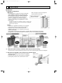
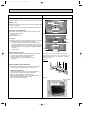
(4) Maintenance for water pump and water pipe
Water pump & Light-type bacteria removing filter
1. Pull out the pipe. 2. Turn the tank
pump to detach.
Water
tank
Tank
pipe
Water pump
Water pipe · Tank holder
3. Pull out the tank pipe, turn the cap
to remove, and then wash
the propeller with water.
Normally the filter need not be replaced. However, replace it
in the following condition:
•When the filter is clogged by passing something other than
water through the filter.
•When the filter is broken.
In such a case, contact the dealer that you purchased this
refrigerator.
Tank pipe
•The propeller is
Propeller
made of the magnet.
Wash it well with water
Cap Cover
so that no alien substance remains on it.
5. Put the parts back in the reverse order of disassembly.
Light-type bacteria removing filter
2. Separate pieces and wash with water. 3. Reverse steps to replace the pipe.
Water
1. Pull out water supply
supply
pipe. Wipe the tank
holder with clean cloth. pipe
•Do not let water flow into
the tank holder.
4. Remove the light-type bacteria removing filter
and wash it in water.
Tank holder
packing
•Twist the
aluminum
pipe to
Aluminum pipe replace it.
(5) Troubleshooting for automatic ice-maker
Side A
Side B
Water pipe
•Replace the water
pipe.
Be sure that sides A
and B fit flush to
each other.
The ice-maker gear box may be defective, cooling may be poor or ice cubes may be full in the server.
•Ice cubes are not stored flatly
➔Inspection
and the amount is detected as
full.
•Food inside the ice server
The ice does not
come out from
the tray
2.Measure the resistance of ice tray thermistor
circuit.
3.Check if the temperature of the freezer compartment is cool enough.
(It takes longer to make ice during summer
time or if the door is frequently opened.)
•Open circuit (∞') or
short circuit (0')
•Not enough
➔Replace the ice tray
thermistor.
➔Poor cooling
Water in
No waterdrops in water saucer water
saucer
The water saucer may be defective, or the ice tray may get cracked.
No water or ice
in the ice tray
Trouble with ice-making
Water or ice is
on the ice tray
1.Check inside of the ice server.
Water in the tank
holder
Chained ice,
Water leaking from
the ice server
4. Check the water pipe between the refrigerator •Clogging
➔Clean the water pipe.
compartment and freezer compartment for dirt, •Freezing (For freezing, check ➔Defrost
the pipe heater resistance.
and foreign objects.
5.Check the condition of ice tray.
•Broken or cracked
•Not placed properly
➔Replace the tray.
➔Reinstall it properly.
6.Disassemble the water pump and check the
inside of the pipe.
•Dirt or foreign objects
7.Tank pipe is clogged , has a hole or is not
properly installed.
•Clogging, disconnecting
•Hole or crack
8.Check the motor coil resistance.
•Open or short circuit
9.Check if there are any dirt or foreign object
which are difficult to remove in the water tank.
Also, check if there is any crack or deformation
on the tank.
10.Check the water pipe for dirt, and foreign
objects. Also, check the water pipe position and
connection.
11.Check the water pipe (between F.compartment
and R.compartment) for clogging.
•Crack or deformation
➔Repair and explain to
the user for proper
usage.
➔Clean / Reinstall it properly.
➔Change the tank pipe.
➔Check the water
pump.
➔Change the water
tank.
➔Clean / Reinstall it
properly.
➔Replace the pipe.
•Clogging
➔Clean / Remove the
dirt.
•Water filling time is longer ➔Replace the control
12.Check the water pump operation by the icethan 9 seconds.
board.
making test.
13.Water spill at the installation of water tank or more water over the full water level may cause to from
chained ice.
14.Measure the water pump coil resistance.
•Open or short circuit
➔Change the water
pump motor.
18
•Clogging, disconnecting
•Hole or crack
06.7.20 9:55 AM
Page 19
6-5 FLOWCHART OF TROUBLE CRITERION
MR-G50J-NZ
Excessive cooling
Are the temperatures of
refrigerator compartment/ set to “Low”?
No
No cooling, poor cooling
Are the temperature of
refrigerator compartment/ set to “High”?
Set the temperatures
to “Low”.
Yes
No
Set the temperatures
to “High”.
No
Proceed to [5] at page
23.
Yes
Only food around the
air blowing part get
frozen
Yes
Open the refrigerator
compartment door with
a magnet on the door
switch to check that
cold air blows from the
outlet.
Keep the food away
from the blowing part
No
Yes
Expose the damper (for refrigerator compartment/ slide compartment) so that its operation can be visibly checked and
conduct an ice-making test. Does the baffle open/close ?
(Wait 1 minute for self-check).
(See “Self check method and its operation,1 Ice making
test operation” at page 14.)
Normal
The baffle does not operate
Replace the motor damper (for refrigerator compartment/ slide chilled
compartment)
❈Motor damper is combined with
control panel assembly.
Yes
Is the motor damper (for refrigerator compartment/ slide
compartment) covered with frost?
Repair the frosted part.
No
Check the refrigerator compartment thermistor
Refrigerator compartment
thermistor abnormal
Put refrigerator compartment thermistor into ice water (0:), disconnect the 4-pin connector, and measure resistance between
3 (white) and 4 (white). •Resistance at 0: :approx. 6-7k".
Check the chilled compartment thermistor
Put chilled compartment thermistor into ice water (0:), disconnect the 6-pin connector, and measure resistance between
3 (white) and 6 (white). •Resistance at 0: :approx. 6-7k".
Cutting jumper wires on operation P.C. board can
change the set temperature of each compartment.
Unscrew the back of operation p.c. board and remove
decoration panel to cut the jumper wires.
Chilled compartment
thermistor abnormal
Refrigerator
compartment
Freezer
Ice making
Refrigerator Slide chilled Slide chilled Versa
compartment compartment compartment compartment compartment compartment
Jumper to be cut JP1
JP2
JP3
JP4
JP5
JP6
Temperature change 1; lowers 1; lowers 1; highers 2; lowers 1; lowers 1; lowers
Weak
Refrigerator Low
compartment
Slide chilled
compartment
w1
Ice
Versa
making compartcompart- ment
ment
Replace the refrigerator
compartment thermistor
Replace the slide chilled
compartment thermistor
Attach a
magnet bar
here.
Operation P.C. board
Cooling
Strong
Middle High Chilled
Refrigerator
4-pin
connector
Chilled
1
2
3
4
CN2A 1 1
55
Control board
[1] Refrigerator compartment/ Slide chilled compartment
OA090-1.qxp
CN7S 4 4
1
2
3
4
6-pin
connector
6 6
5 5
4 4
3 3
2 2
1 1
88
11
CN4D 9 9
00
11
22
19
Jumper
L Refrigerator compartment room light
Refrigerator compartment
thermistor
Slide chilled compartment
thermistor
Motor damper
M (for refrigerator compartment/
slide compartment)
OA090-1.qxp
06.7.20 9:55 AM
Page 20
[2] Freezer compartment
Poor cooling
No
1 Is the set temperature of freezer compartment set to “High”?
Set the temperature to “High”.
Yes
No
2 Does cool air come out of air outlet?
Proceed to “The refrigerator fan motor does not work.”
Yes
The baffles
do not
function.
3 Operate the ice-making test at the place where the operation of
dampers (Refrigerator compartment and slide compartment thermistor) is visible. Does the baffle open / close? (Wait 1 minute for
self-check).
(See “Serf-check and error display method and operation, 1 Ice
making test operation” at page 14.)
Normal
Replace the motor damper (for freezer compartment ).
wReplace the fan grille as well as the motor
damper since they are combined together.
When compressor
operates, LCD indicates e41 as a
result of self-check.
Normal
4 Check freezer compartment thermistor.
Defective thermistor
Replace freezer compartment thermistor
CN7S
Control board
Dip freezer compartment thermistor into ice water (0:), and
measure the resistance between terminal 3 (white) and 6
(white) by detaching 6-pin connector at the left-back bottom of
vegetable compartment.
•Resistance at 0: :approx. 6~7k".
CN4D
44
44
Exchange
the unit
6-pin connector
6 6
5 5
4 4
3 3
2 2
11
44
55
66
33
Freezer
compartment
thermistor
Motor damper
(for freezer
M compartment)
[3]
Compressor does not operate
Not cooling at all(In case any error codes doesn’t appear as shown in page 21,22 even though mode switch is pressed for 5 seconds)
Yes
Is refrigerator in the demonstration mode?
Release the demonstration mode. (See page 10.)
No
Does AC 230V run between 1 and 3, terminals of CN1 on filter board?
No
Inspect power-supply wiring such as power cord and
breaker etc.
Yes
Does AC 230V run between 3 and 5, terminals of CN2 on filter board?
No
Replace the filter board.
Yes
Detach each connector CN2A on
control board check the continuity
between terminals 5 and 7
respectively.
(Check if there is a short or open
circuit in the motor protector.)
No
continuity
Motor protector (open circuit)
wBy measuring the resistance,
ensure that the circuit is open.
Abnormal
Continuity detected
Detach connector CN50G on control board and check the resistance respectively between terminals of 1,3 and 5:approx.9.3"
No
continuity
Disconnect 6-pin connector in
machine chamber to check resistance between terminals of 1, 2
and 3: approx.9.3"
Continuity detected
Check the error display of selfcheck after turning on and off the
power supply.
wWith all the connectors connected.
Normal
Check connector contact.
Abnormal
Abnormal
Measure the resistance of compressor’s winding between terminals of black, white, and red :
approx.9.3"
Exchange the unit
Normal
6-pin connector in machine chamber
Inverter-related parts may be
defective. Conduct ice making
test operation. (see page 21 for
error codes.)
Filter board CN1
11
33
Noise filter
CN2
5 7
57
CN2A
13
5
135
CN50G
11
33
Control board
20
1 1
2 2
3 3
4 4
55
M
M
Compressor
Motor
protector
Replace the lead wire
assembly (Lead wire of
compressor)
OA090-1.qxp
06.7.20 9:55 AM
Page 21
Inverter-related indication “Compressor does not operate”
Error
code
e50
e51
Abnormality
Possible cause
Symptom
Treatment
Trouble of
inverter circuit
•When there is
Compressor Replace the control board.
any trouble in the does not
circuit which
rotate.
detects phase
current of compressor.
Bus-bar
voltage is
abnormal.
•Power supply
voltage is
abnormal.
Compressor
does not
rotate.
Start
Arrange
160V or power supmore ply to obtain
Measure the voltage of
the rated
power supply.
voltage,
180-280V.
280V or more
•Defective reactor
on the N/F board
Arrange power supply to make the voltage
within 180-280V and conduct the following
checks.
Check the
Does AC230V run
between CN51 ter- No connection
between filter
minals 1 and 3, on
the control board?
board and
(See page 32.)
control board.
Yes
Replace the
control board.
e52
•When the inverter Compressor
Trouble of
inverter software driving software does not
malfunctions.
reset function
rotate.
Abnormal
Connect
them
properly.
Normal
Replace the
filter board.
Unplug the power cord and then plug it in 10 minutes.
Check the error code by performing the ice making test operation.
e52 display again.
No error code display
Replace the control board.
e53
Compressor
•Abnormal start- •Compressor
up
motor gets locked. does not
•Defective circuit rotate.
•Abnormal
synchronization on control board
•Defective contact
of CN50G on
•Trouble of
overcurrent
control board
detection
•Defective contact
of machine
chamber 6-pin
connector
Explanation to customer
Start
Disconnect 6-pin
connector in
machine chamber to check
No
resistance
between each
terminal of 1, 2
and 3: Are they
approx. 9.3'
(20:)?
Yes
*Replace
Measure the
resistance of
compressor’s
winding
No
between each
terminal of 1,
2 and 3: Are
they approx.
9.3' (20:)?
Yes
lead wire assembly C.
*Is compressor No Check the connection of the
connector CN50G on the
energized at
control board or the machine
startup?
chamber 6-pin connector.
Yes
Exchange
the unit
Abnormal
Normal
Replace the
control board.
*If control board is normal, compressor is energized
every 10 minutes.
Compressor vibrates at startup when it is being energized. Touch it with your hand to check.
21
Exchange
the unit
Connect them
properly.
OA090-1.qxp
06.7.20 9:55 AM
Page 22
Inverter-related indication “Compressor does not operate”
Error
code
e56
Abnormality
•Defective wiring
continuity
•Trouble of the
control board
Possible cause
Symptom
•Defective connec- (1) or (2)
tion of connectors (1)Compres
sor can
related to comnot be
pressor
activeted
(board-side,relay,
for more
comp-side)
than 1.5
hours
•Defective wiring
continuity of the
(2)Overcurr
compressor
ent
•Trouble of control
detection
error
board
occurred
•Trouble of
before
compressor
the compresssor
is
actived.
Treatment
1.Locate the trouble and deside the treatment
•Decide the treatment by checking the followings.
(1) Defective connector connections.
(board-side,relay,comp-side)
(2) Resistance of compressor’s winding
2.Flowchart of troubleshooting
Check
Treatment
start
Connector CN50G on the
control board is properly
connected?
No
Connect properly.
Yes
6-pin relay connector in machine
chamber is properly connected?
No
Yes
Compressor
6-pin relay connector in machine chamber
The connector of compressor
is properly connected?
No
Control board
Point+2 (to measure resistance)
For checking the connection
to compressor
Lead wires connected
to compressor
Yes
Point+1 (to measure resistance)
For checking the relay
connection
Disconnect 6-pin relay
connector in machine
chamber and measure
the resistance
between each terminal
of 1 ,2 and 3 (Pont 1).
Approx.
9.3"(At 20:)?
No
Yes
Is compressor being
energized at startup?
Measure the
resistance of
compressor’s
winding
between each
terminal
(Point 2).
Approx.9.3"
(At20:)?
No
Exchange
the unit
Yes
Replace the lead wire connected to compressor.
No
Replace the control board.
Yes
Exchange the unit
Replace it only when error display
keeps blinking even though all the
above mentioned connectors are
properly connected.
3.Recheck after treatment
•After any treatment is tried, unplug and plug power cord
again to check if the compressor operates properly.
•If the compressor can operate properly for more than 1
minute after power cord is plugged again, it’s presumed
that the couse of trouble is eliminated.
*If the couse of trouble cannot be eliminated,”e56” will be
displayed again 1 minute later after the power cord is
plugged again.
*If the control board has been replaced,e56 won’t be displayed even though the couse of trouble is still not eliminated. In such a case,perform the ice making test operation to check what the error is. At the same time, also confirm that the compressor is operating for more than 3 minutes and each compartment is getting cooled.
22
06.7.20 9:55 AM
Page 23
[4] Poor defrosting
Poor cooling
1 Short-circuit the terminal ➀ and ➁ of the compulsory
defrosting terminals (CN1M) of the filter board to actuate
the compulsory defrosting function and check whether the
defrost heater is working properly.
*1
Yes (heats up)
Check the following: half-open door,
space between gaskets, the amount
of ice.
No
2 Check if there is continuity between thermal fuse
No
Replace the defrost heater and the
thermal fuse.
and defrost heater.
Control board
Yes
Check the resistance of the defrost
thermistor.
CN7S
<Control board>
44
99
Short circuit
4-pin connector
CN2A
9-pin connector
3 3
33
1-pin connector
55
22
44
1
1
2
1
1
2
1
CN1
Compulsory defrosting
Thermal fuse
*1 The compulsory defrosting will
not work when the temperature
of the defrost thermistor is 14:
or more.
Defrost heater
Defrost thermistor
2-pin connector
1 Plug and unplug the power cord to perform self-check on
Yes
Replace refrigerator fan motor.
refrigerator fan motor. Is the lamp indicating abnormality?
No
2 Plug and unplug the power cord to check if
Not rotating
machine chamber fan motor is rotating.
Room light is
not turned on
and off.
Running
Note: Refrigerator fan motor is combined
with fan grille.
Check if CN4D connector on control
board is connected properly.
If it is, replace the control board.
4 Check the continuity by
3 Check the door switch for continuity.
Abnormal
disconnecting the CN7S
on the control board.
(See figure below.)
•Open and close the refrigerator door b several times
and check if the room light will be turned on and off
(Room light should get turned off when the door comes
10mm close to the refrigerator body a.)
•Close the refrigerator compartment door until the light is
turned off a. Open and close the ice-making-compartment door c, and from the space of refrigerator compatment door, check that the room light is turned on and off.
Normal
Contact failure of
connector.
Connect it properly.
Check if the connector on
the door switch is connected properly. If it is, replace
the door switch.
Room light is turned on and off properly.
5 Check if there is continuity in 6-pin fan motor connector in
No continuity
versa compartment.
Continuity detected
Connect the connectors properly.
Replace refrigerator fan motor.
Door switch for refrigerator compartment (right and left) and ice making compartment.
Doors
Note: Refrigerator fan motor is combined
with fan grille.
R-door (right, left): closed
Door of the ice making
compartment : closed
Any one of the doors
are open
wIf any one of those doors are open, the switch between
1 and 2,terminals of 2-pin connector, will be OFF)
1
etc
2-Pin connector
Between
1
and
44
33
2
OFF
2
8-pin
connector
CN7S
Control board
[5] The refrigerator fan motor does not work
OA090-1.qxp
8 8
77
ON
Lead Switch board
Refrigerator compartment
2-pin
(right and left)/ Ice making
connector
compartment door switch
22
11
10~
a
CN4D
6 6
8 8
5 5
3 3
6-pin
connector
4-pin
connector
1
2
4
3
4
3
2
1
1
2
4
3
4
3
2
1
M
23
Refrigerator
fan motor
50m
b
m
tor
era
efrig
r
r of
f
Doorsa rtment
ro t
ve mpa
doo tmen
ice
o
f
c
o
Left mpart
r
Doo king ent
co
ma rtm
e
c compa
tabl
ege
of vtment
r
o
Do mpar
zer
co
free t
r of rtmen
o
o
a
D mp
co
r
rato
frige
e
of r
oor t
ht d rtmen
g
i
R mpa
co
OA090-1.qxp
06.7.20 9:55 AM
Page 24
Is the temperature of
vegetable compartment
set to “Low”?
poor cooling
Is the temperature of
vegetable compartment
set to “High”?
Set the temperature to
“Low”.
No
No
Set the temperature to
“High”.
Yes
Set the temperatures to
“Middle” or “High”.
Yes (Go to 1 or 2 )
Yes
1 Check the thermistor, vegetable compartment
heater, and control board.
No
(Go to 1 or 2 )
Is one of these error codes indicated when conducting self-check of operation P.C. board?
No error code is
indicated.
Yes
Replace the Filter board.
Yes
Is there a short or open circuit in each thermistor and is
the resistance 0" or ∞"?
e13, e14 or e16 is indicated.
Does vegetable compartment have a resistance of
approx. 2.9k" between wireconnected terminal 5(CN2A)
and 7 (CN3A) on control
board (parallel resistance
between vegetable compartment heater 1 and 2)?
Are the temperatures of
refrigerator compartment/ freezer compartment set to “Low”?
e18 is indicated.
Refrigerator compartment thermistor: e13
Slide chilled compartment thermistor: e14
Vegetable compartment thermistor: e16
Outside air thermistor: e18
0"
Replace the defective
thermistor.
No
Check the contact of connector connecting each
thermistor and connector
CN7S on control board. Fix
the incomplete contact.
0"
or
Is there a resistance of
approx. 5.9k" between
5 and 6, terminals of 6pin connector which is
It may have contact failure of
connector. Recheck the contact located at the right top
after the 6-pin or 2-pin connector of fan grille?
is connected.
or
∞"
∞"
Replace the vegetable
compartment heater 1.
Yes
Note: Vegetable compartment
heater 1 is combined with
fan grille.
Is there a resis0"
tance of approx.
or
5.9k" between 1 ∞"
and 2, terminals
Replace the vegetable
of 2-pin connector
compartment heater 2.
which is located
at the left-back
Note: Vegetable com
bottom of vegpartment heater 2
etable compartis combined with
ment?
When outside temperature is 32: or less and compartment temperature is
8: or less, set the temperature of each compartment as follows.
Refrigerator compartment: High
Slide chilled compartment: Chilled
Versa compartment:
Soft freezing
Freezer compartment:
High
Is there voltage AC230V between connector CN2A 5 (Gray) and CN3A 7
(Yellow green) on control board?
Measure the voltage for over 10 seconds.
When an analog tester detects AC 230V, consider the control board normal.
(230V is outputted on every 10 seconds.)
partition V/ F.
Yes
Yes
No
Replace the control board.
Check if doors are hermetically closed.
2 Check refrigerator / slide chilled compartment is excessively cooled (poorly cooled).
Follow the refrigerator / slide chilled compartment flowchart on page 19.
OK
4-pin connector
Explain proper usage to customer
3 3
4 4
Refrigerator
compartment
thermistor
6-pin connector
CN3A 7 7
Control board
[6] Vegetable compartment
Excessive cooling
5 5
6 6
33
Slide
chilled compartment thermistor
6-pin connector
6 6
CN2A
2-pin connector
55
1 1
2 2
CN7S 4 4
11
88
CN8K 1 1
22
44
Vegetable
compartment
heater 1
Operation P.C. board
4-pin connector
4
3
2
1
1
2
3
4
4
3
2
1
24
1
2
3
4
Outside air
thermistor
TH1
Vegetable
compartment
heater 2
06.7.20 9:55 AM
Page 25
only applies to versa compartment.
Excessive cooling
No cooling; poor cooling
Which operation mode is versa compartment set to?
Which operation mode is
versa compartment set to?
It is set to “Soft freezing”.
It is set to
“Vegetable •
Refrigerator” or
“Chilled”.
Is the
No
temperature
set to “Low”?
It is set to ,
“Vegetable •
Refrigerator” or
“Chilled”.
It is set to “Soft freezing”.
It is set to “Freezer”.
Is the temperature set to “High”.
Set the temperature to “Low”.
Yes
No
Set the temperature to “High”.
Check the set temperature in freezer compartment. Is the temperature set to “High”?
Yes
w1
Only the food around
cool-air outlet is excessively cooled.
Yes
No
Does cool air come out
of air outlet when opening the refrigeratorcompartment door and
attaching a magnet bar
on the door switch?
Keep food away from
air outlet in storing food.
No
Set the temperature to
“High”.
Refer to the section:
“The refrigerator fan
motor does not work”.
No
Yes
Make the operation of
The baffles
motor damper (for ice
do not function Is connector CN9D on
control board connected
making compartment/
properly?
versa compartment)
visible, and conduct ice
making test. Check that
Yes
the baffles open and
close.
Disconnect CN9D and measure
(Wait one minute for selfthe resistance between 1 and
check.)
2, and between 3 and 4.
Check that the winding of motor
(See “• Self-check and
damper (for ice making comparterror display method and
ment/ versa compartment) has a
operation, 1 Ice making
resistance of approx. 415"
test operation” on page
14.)
No
Connect the connector
properly.
No
0"
or
Is 6-pin connector which is in connector cover
on the back of versa compartment connected
properly?
(6-pin connector is connected to motor damper.
Refer to the figure below.)
∞"
Yes
Replace the motor damper (for ice making compartment/ versa compartment)
wReplace the fan grille as well as the motor
damper because they are combined together.
Normal
Normal
Is the motor damper covered with frost?
Frosted
Repair the frosted part.
Not frosted
Check the versa compartment thermistor.
Dip the versa compartment thermistor into the ice water
(0:) and disconnect 6-pin connector for fan grille at the
back of versa compartment. Measure the resistance
between terminal 3 (white) and 6 (white).
•Resistance at 0:: Approx. 6~7k"
Defective thermistor
Replace the versa
compartment thermistor.
Defective thermistor
Replace the ice making
compartment thermistor.
Check the ice making compartment thermistor.
Dip the ice making compartment thermistor into the ice
water (0:) and disconnect 6-pin connector of fan grille
at the back of ice making compartment. Measure the
resistance between terminal 1 (white) and 4 (white).
•Resistance at 0:: Approx. 6~7k"
CN7S 4 4
7 7
5 5
Control board
[7] Versa compartment/ Ice making compartment
OA090-1.qxp
8-pin connector
Ice making
compartment
4-pin connector
thermistor
9 9
8 8
1 1
33
w1
6-pin connector
6
5
4
3
2
1
CN9D 3 3
2 2
4 4
11
25
6
5
4
3
2
1
Versa
compartment
thermistor
Motor damper
M (for ice making
compartment/
versa compartment)
Refrigerator
compartment
Ice
Versa
making compartcompart- ment
ment
Attach a
magnet bar
here.
OA090-1.qxp
06.7.20 9:55 AM
Page 26
6-6 TROUBLE CRITERION OF MAIN PARTS
MR-G50J-NZ
Components/
Part Name
Parts Mounted
Position
Check Method and Criterion
Compressor
ETI100E13DAH
Model
Black
Rated input
Starting current
Running current
White
W
A
A
45/159 (1620/4800rpm)
2.0
0.03/2.19 (1620/4800rpm)
Red
Measure the resistance
with a tester.
Motor
protector
Winding
(Black-White)
(White-Red)
(Red-Black)
Normal
Abnormal
(faulty)
9.3 '
(20:)
Open (∞' )
or
short circuit
(0' )
MM3-71CCV
Model
Connected
point
In the machine
chamber at the
rear side of the
frame.
Open
100 ±50 : or more
Energize it at 17.0A, 25: for 16 seconds at the longest.
Close
61±8: or less
In the machine
chamber at the
rear side of the
frame.
Measure the resistance with a tester. (Ambient temperature : Room temperature)
Contact point
1
1
2
Normal
Abnormal (faulty)
Less than 1'
Open circuit (∞' )
2
Refrigerator
fan motor
In the fan grille
of the freezer
compartment.
UDQM002B3
Model
DC brushless
Number of pole
10
Diameter
{150 (Mixed flow fan)
Measure the resistance with a tester. (Ambient temperature : Room temperature)
Normal
Abnormal
(faulty)
Between 1 and 4 (GND and IC Between 1 and 4
: open circuit (∞' )
Power): About 12 k'
Between 3 and 4 (Power and
IC Power): ∞'
4
3
2
1
IC
Between 3 and 4
:short circuit (0' )
IC Power
Power
FG
GND
1 2 3 4 : Pin No.
Machine
chamber fan
motor
UDQM004B3
DC brushless
Number of pole
10
Diameter
{140 (Extra fan)
Operation method
During compressor operation
Measure the resistance with a tester. (Ambient temperature : Room temperature)
Normal
Abnormal (faulty)
Model
IC
1 2 3 4 : Pin No.
4
3
2
1
IC Power
Power
FG
GND
Between 1 and 4 (GND and IC Between 1 and 4
: open circuit (∞' )
Power): About 9 k'
Between 3 and 4 (Power and
IC Power): ∞'
26
Between 3 and 4
:short circuit (0' )
In the machine
chamber at the
rear side of the
frame.
OA090-1.qxp
06.7.20 9:55 AM
Page 27
Components/
Part Name
Water pump
motor
Motor damper
for refrigerator
compartment/
slide chilled
compartment
Parts Mounted
Position
Check Method and Criterion
Measure the resistance with a tester. (Ambient temperature : Room temperature)
Normal
Abnormal (faulty)
Open (∞' ) or
16' (Approx.)
short circuit
(0' )
Measure the winding resistance.
Winding
Blue-White
( Red-Yellow
)
Normal
Abnormal (faulty)
415'
(Approx.)
Open (∞' ) or
short circuit
(0' )
Under the water
tank holder in
refrigerator compartment.
In the control
panel for
refrigerator
compartment.
Connector is at
the left-back bottom of refrigerator compartment.
Red
Yellow
Blue
Motor damper
for ice making
compartment/
versa compartment
White
Measure the winding resistance.
(
Winding
Blue-White
Red-Yellow
)
Normal
Abnormal (faulty)
415'
(Approx.)
Open (∞' ) or
short circuit
(0' )
In the fan grille
for freezer
compartment.
Connector is at
the back of versa
compartment.
Red
Yellow
Blue
Motor damper
for freezer compartment
White
Measure the winding resistance.
(
Winding
Blue-White
Red-Yellow
)
Normal
Abnormal (faulty)
415'
(Approx.)
Open (∞' ) or
short circuit
(0' )
Red
Yellow
Blue
27
White
In the fan grille
for freezer
compartment.
Connector is at
the left-back bottom of vegetable
compartment.
OA090-1.qxp
06.7.20 9:55 AM
Page 28
Components/
Part Name
Defrost heater
Parts Mounted
Position
Check Method and Criterion
163
The heater is energized while defrosting.
Operation method
(Defrosting is finished when the evaporator is 14± 1.5: or more)
Rated input
W
Measure the resistance with a tester. (Ambient temperature : Room temperature)
Vegetable
compartment
heater 1
325'
(Approx.)
Open circuit (∞' )
Normal
Abnormal (faulty)
5.9k' (Approx.)
Open circuit (∞' )
Normal
Abnormal (faulty)
5.9k' (Approx.)
Open circuit (∞' )
In partition V/F.
The heater is turned on when vegetable compartment
thermistor has reached a lower temperature than the set
temperature for vegetable compartment.
Measure the resistance with a tester. (Ambient temperature : Room temperature)
Operation method
In the fan grille
at the back of
vegetable
compartment.
The heater is turned on when vegetable compartment
thermistor has reached a lower temperature than the set
temperature for vegetable compartment.
Measure the resistance with a tester. (Ambient temperature : Room temperature)
Operation method
Water pipe
heater
Abnormal (faulty)
Measure the resistance with a tester. (Ambient temperature : Room temperature)
Operation method
Vegetable
compartment
heater 2
Normal
At the drip tray
under the evaporator of the
freezer
compartment.
Normal
Abnormal (faulty)
6.6k' (Approx.)
Open circuit (∞' )
When ice-making thermistor has reached approx. 10; or
below, the heater is turned on with energizing rate adjusted by the set temperature of slide compartment and
freezer compartment.
28
Under the water
tank holder.
OA090-1.qxp
06.7.20 9:55 AM
Page 29
Components/
Part Name
Divider
heater (I/S)
Measure the resistance with a tester. (Ambient temperature : Room temperature)
Operation method
Rotational
heater board
Normal
Abnormal (faulty)
9.6k' (Approx.)
Open circuit (∞' )
Normal
Abnormal (faulty)
6.6k' (Approx.)
Open circuit (∞' )
In the rotational
heater board of
refrigerator
compartment.
While compressor is operating, the heater is turned on.
When compressor stops, the heater is suspended for the
first 20 minutes and then reactivated.
Measure the resistance with a tester. (Ambient temperature : Room temperature)
Operation method
In partition I/S.
While compressor is operating, the heater is turned on.
When compressor stops, the heater is suspended for the
first 20 minutes and then reactivated.
Measure the resistance with a tester. (Ambient temperature : Room temperature)
Operation method
Ice making
tray heater
Parts Mounted
Position
Check Method and Criterion
Normal
Abnormal (faulty)
4.8k' (Approx.)
Open circuit (∞' )
During CRYSTAL ICE mode
(The heater is turned on 10 minutes after water is
supplied, until 5~6 hours.)
29
Lower part
of ice tray
OA090-1.qxp
06.7.20 9:55 AM
Page 30
Components/
Part Name
Parts Mounted
Position
Check Method and Criterion
Measure the resistance with a tester according to the following graph.
(Thermistor resistance values against temperature)
Thermistor
•Resistance measured under the ambient temperature from -50: to +50:
1. 200' to 500k' ·····················Normal
2. Out of the above range ·········Abnormal
Thermistor Check Procedure
•Thermistor
resistance value will vary
Slide chilled
compartment
with the change of temperature.
Thermistor resistance •Take the temperature around the
Ice making tray
thermistor
values against temperature thermistor, and then measure thermistor
Freezer
compartment
resistance using a tester.
Outside air thermistor
Defrosting
The relation between resistance and
(In the operation
temperature is as shown on the left side.
Versa
P.C. board)
Refrigerator
compartment
(k')
35
30
compartment
Ice making
compartment
Resistance values
25
Vegetable
compartment
20
10
5
0
-20
0
-10
10
20
30
(;)
Temperature
Three-way
valve
(1)If the self-check indicates the abnormality of thermistor when the power is
turned on, measure the resistance of the
thermistor.
•If there is a short circuit in the thermistor, there may be a defect in the contact
of the connector or the element of the
thermistor.
(2)When the self-check indicates the
abnormality of thermistor a few seconds
after the power is turned on, check the
contact of the connector.
A 5
Model
NSCE001DC1
Normal
Abnormal
54~56' (Gray
[common] A/ A/ B/
B each phase)
Open (∞' ) or
short circuit
(0' )
A 2
1
3
4
B COM B
1
2
3
4
Ice making
thermistor,
Versa
compartment
thermistor,
Vegetable
compartment
thermistor
and Freezer
compartment
thermistor
In the fan grille
of each
compartments.
Troubleshooting with self-check
Inner
thermistor
15
Defrost
thermistor
Evaporator
5
B A COM B A
Check the operation of three-way valve
Check the operation by following either (1) or (2) below. When a popping sound is
heard 1 to 25 times, it is considered that the valve is operating normally. The sound
is clearly heard around the back of the product.
(1) Reset the power supply. Check the operation right after this.
(2) Ice making test. Check the operation right after the test is over.
30
Ice making
tray
thermistor
In the ice
making
compartment.
Outside air
thermistor
In the operation
P.C. board.
In the machine
chamber at the
rear side of the
frame.
OA090-2.qxp
06.7.20 9:56 AM
Page 31
Components/
Part Name
Vegetable compartment LED
(12V DC)
Parts Mounted
Position
Check Method and Criterion
Normal condition
Timing in
making contact
Abnormal
condition
•The pointer of the tester equipped with a diode range shakes
when measuring the resistance between 4-pin connector
No.3(-) and No.4(+).
•Use a tester equipped with a diode range (
) for
judgement.
In the fan grille.
Electricity is supllied all the time.
•The pointer of the tester equipped with a diode range does
not shake when measuring the resistance between 4-pin
connector No.3(-) and No.4(+).
•Make sure that the pointer of the tester does not shake even
if the polarities are reversed.
•Resistance: Short-circuited (0')
LED shown in the figure on the right turns orange in the above timing.
Note: LED cannot be replaced individually because it is combined with the fan grille.
LED
LED for bacteria
removal from
water tank
(12V DC)
Timing in
making contact
Abnormal
condition
Use a tester equipped
with a diode range
(
).
•After water is supplied to the ice tray.
•After the ice level sensor lever detects that ice storage
becomes full.
•While the door is kept open for maximum of 5 minutes.
When the door is opened, LED goes out within 5 minutes.
wMake sure if the connector is securely connected.
LED
Note: LED cannot be replaced individually because
it is embedded in the tank holder.
6-7 TEST POINT DIAGRAM OF FILTER BOARD
Earth
MR-G50J-NZ
AC230V
230V
31
On the external
surface of the
tank holder.
}
}
}
}
}
5 W phase
3 V phase
1 U phase
Damper for refrigerator
compartment / slide compartment
Damper for freezer
compartment
Damper for ice making
compartment / versa compartment
Electromagnetic three-way valve
Power suplly of three-way valve
LED for bacteria removal from water tank
}
}
}
}
GND
GND
Machine chamber fan motor (+)
Refrigerator fan motor FG signal
Machine chamber fan motor / Refrigerator fan motor driver IC powe source
Machine chamber fan motor FG signal
Fan motor +
GND
Ice maker position switch
Water pump Ice maker (reverse)
Ice maker (rotation)
Reception of operation panel data
Power supply to operation panel data
1
2 Vegetable compartment LED
3 Door switch input
4 Freezer compartment thermistor
5 Ice making compartment thermistor
6 Vegetable compartment thermistor
7 Versa compartment thermistor
8 Slide chilled compartment thermistor
9 Defrost thermistor
10 Ice making tray thermistor
11 Refrigerator compartment thermistor
12
13
14 5V com
1
2
3
4
5
6
7
8
1
2
3
4
5
6
7
8
9
10
11
12
13
14
15
16
1
2
3
4
5
6
7
8
9
10
11
12
1 Ice tray heater
3 Water pipe heater
5 Divider heater (I/S)
7 Vegetable compartment heater 1, 2
9
11 Rotational heater board
32
CN7S
CN8K
CN4D
CN9D
CN3A
+
–
+
–
+
–
}
DC+12 ~ 20V
(Inverter circuit)
DNG
DC280 ~ 330V
DC +5V
(Inverter circuit)
Compressor
}
+
DC+12
~ 13V
(Refrigerator
control
circuit)
–
}
+
DC+5V
(Refrigerator
control
circuit)
–
3 Defrost
heater
1 Refrigerator
compartment
}
~
AC
230V
}
7
5
Page 32
06.7.20 9:56 AM
OA090-2.qxp
6-8 TEST POINT DIAGRAM OF CONTROL BOARD
MR-G50J-NZ
Compulsory
defrosting by
short circuit
CN2A
OA090-2.qxp
06.7.20 9:56 AM
7
Page 33
NAMES OF THE PARTS
MR-G50J-NZ
MODE
button
Operation panel
Fast cooling button
SELECTION
button
ECO button
REF VEG L D
REF
VR
Min CHILL
: SOFTF
QCK QCK ICE L M H
M
VEG
REG ICE F Z R H
FZR ECO CRL ICE ICE(STOP) DEO
Refrigerator compartment
Two-way
flexishelf
Height adjustable shelf
Free
pocket (L)
Free pocket (S)
Lid of slide
chilled case
Three-way flexishelf
Small item case
Slide chilled case
Tube stand
Bottle
pocket (L)
Alumi-num tray
Bottle pocket (S)
Free egg shelf (S)
Water tank
Automatic ice maker
(Ice making compartment)
Ice making compartment is
applicable to refrigerator and
freezer compartment.
Versa compartment
Versa compartment is applicable to freezer, soft freezing,
chilled and refrigerator vegetable.
Versa compartment is set to refrigerator vegetable mode at factory shipping.
●
●
Water tank (app. 1.2L)
Water supply port cap
Water tank lid
Pipe
Water supply pump,
Light-type bacteria
removing filter
Water supply pipe
Ice storage bin
Ice server
V-LED lamp
Ice tray
❈Can not be
removed.
Sound proof
mat
❈Reduces the
sound of ice
dropping into
the storage
corner.
Do not remove
the mat.
Freezer compartment
Vegetable compartment
Sliding case
Freezing case
(upper)
Partition pocket
Vegetable
stand
Versa case
Vegetable case
2L-plastic bottles
can be put into
the case.
33
Freezing case
(lower)
OA090-2.qxp
8
06.7.20 9:56 AM
Page 34
DISASSEMBLY INSTRUCTIONS
MR-G50J-NZ
Plug out before work!!
Check the automatic ice-maker pressing ice making stop switch.
In assembling & disassembling parts seven kinds of screws and rivets are used. Do not mistake to use them.
A
B
4✕12
4✕12 (Black)
Stainless steel With metal washer
C
E
D
4✕16 (White)
Specified screw
With plastic washer
G
F
Rivet
Rivet
OPERATING PROCEDURE
5✕16
Stainless steel
PHOTOS
1. Elect cover ➔ Control board
Photo 1
Rivet E
(1)Remove 5 screws fixing the elect cover and the rivet E on the
upper rear side of the refrigerator. (See photo 1)
Control board
(2)Disconnect the connector to remove the control board.
Elect cover
Caution on assembly
Firmly connect the lead wires and the connector. Ensure the
wires are not pinched.
5 fixing screws
2. Parts inside the refrigerator compartment: Vertical partition
Photo 2
Right rail of the
slide compartment
➔ Right rail of the slide compartment ➔ Left rail of the
slide compartment ➔ Room light cover ➔ Control panel
(Upper/ Lower), Duct R (Upper/ Lower)
(1)Remove the three way flexishelf, slide chilled case, and height
adjustable shelf, two way flexishelf from the refrigerator
compartment.
Control panel
Vertical partition
1Remove the small item case and the slide chilled case.
2Pull out the ceiling by unhooking the front catches on both
sides.
3Remove the slide chilled case lid.
4Remove the vertical partition.
Ceiling of slide chilled compartment
Slide chilled case lid
Small item case
Small item case
(with free egg
shelf (S))
Photo 3
Left rail of the slide
compartment
Screw G
Slide chilled case
Control panel
Vertical partition
Photo 4
Right rail of the slide compartment
Catches
(2)Slide the right rail out toward you. (See photo 2 )
Room light
Left rail of the slide compartment
(3)Remove screw G (one screws),and slide the left rail out toward
you. (See photo 3)
Room light cover
Room light cover
1Push up the lower catch, and pull the room light cover toward
you.
2Detach two upper catches to take out the cover.
(See photo 4)
Catch
34
OA090-2.qxp
06.7.20 9:57 AM
Page 35
OPERATING PROCEDURE
PHOTOS
Control panel (upper/ lower) Duct R (upper/ lower)
(4)Remove rivet E, and pull out the mirror hinge on the lower left
of the control panel to remove the connector. (See photo 5)
(5)Remove rivet F (two rivets) in the upper left and right side,
screw A (two screws) in the lower left and right side, and rivet
F (two rivets) in the lower. left and right side.
Detach catches (seven places).
(See photo 5)
(6)Detach catches (six places) on control panel (upper/ lower) and
then duct R (upper/ lower).
w Control panel can be divided into the upper and lower part by
detaching catches (three places) on control panel (upper/ lower)
Photo 5
Catch
Catch
Rivet F
Rivet F
Catch
Catch
Rivet F
Rivet F
Control panel assembly
(The assembly consists of the following: Control panel [upper/
lower], motor damper for refrigerator compartment / slide chilled
compartment, refrigerator compartment thermistor, slide chilled
compartment thermistor, room light socket, refrigerator compartment room light, and duct R [upper/ lower]).
Screw A
Caution on assembly
Mirror hinge
Rivet E
To prevent poor contact of connectors, connect them properly.
Fix the control panel by inserting the lower catches (two places)
into the floor of refrigerator compartment.
3. Parts inside the ice making compartment, versa compart-
Photo 6
ment, vegetable compartment, and freezer compartment ➔
Partition I/ S ➔ Partition I/ S/ V ➔ Cover (IM) ➔ Automatic
Ice maker assembly ➔ Cover (lower) ➔ Partition V/ F ➔
Connector cover (right/ left) ➔ Fan grille ➔ Defrost heater,
Drip tray, DEF thermistor
(1)Remove interior parts out of ice making compartment,
versa compartment, vegetable compartment, and freezer
compartment.
(2)To detach them, pull out the doors of ice making
compartment, versa compartment, vegetable
compartment, and freezer compartment.
Catches
Screw A
Control
panel
(lower)
Partition I/ S
Rivet E
Partition cover
Screws C
Rollers
Rollers
Partition I/ S/ V
Photo 7
Tank holder
Screws A
Partition I/ S
(3)Remove rivet E (one rivet), partition cover, and a connector.
Remove screw C (two screws) at the front side of refrigerator
and four rollers to pull out the partition.
(See photo 6)
Screws A
Screw D
Caution on assembly
Screw D
Partition I/ S/ V
Push up the lead wires so that they will not rub partition I/ S.
Partition I/ S/ V
Photo 8
(4)Remove screw A (two screws) at the front of refrigerator.
Remove screw A (one screw each) and screw D (one screw
each) at the right and left side of inner wall.
Then lift up the partition.
(See photo 7)
Cover (IM)
Catch (Automatic Ice
maker assembly)
Tank holder
Automatic Ice
maker assembly
Cover
(5)Remove 2 rivets E and 3 catches in order to detach the cover.
(See photo 8)
Cover (IM)
Automatic ice maker assembly
Rivet E Catches Rivet E
(Cover)
(6)Pressing a catch upward, and pull Automatic Ice maker
assembly to the right side. (See photo 8)
35
OA090-2.qxp
06.7.20 9:57 AM
Page 36
OPERATING PROCEDURE
PHOTOS
Photo 9
Cover (lower)
(7)Remove rivet E (one rivet) to detach the cover (See photo 10)
Fan grille
Connector
Screws A
Partition V/ F
(8)Remove screw A (four screws) on inner wall and screw A (two
screws) at the front.
Detach three connectors and lift up the partition. (See photo 9)
Partition V/ F
Connector cover (right/ left)
(9)To detach connector cover, remove rivet E (two rivets each)
and catches (two places).
(See photo 10)
(10)Detach the connector.
Screws A
Photo 10
Catches
Fan grille
Rivet E
(11)To detach fan grille, remove screw B (two screws) of right and
left side and remove upper catches (three places).
w Fan grille consists of the following: motor dampers (for icemaking compartment/ versa compartment, and freezer compartment), refrigerator fan motor, fan, thermal fuse, vegetable
compartment heater 1, four thermistors, vegetable compart
ment LED.
(See photo 10)
Rivet E
Connector cover (left) Connector cover (right)
Cover (lower)
Rivet E
Screws B
Fan grille
Defrost heater , Drip tray
(Fan grille consists of the following: motor dampers (for ice
making compartment / versa compartment, and freezer
compartment), refrigerator fan motor, fan, thermal fuse, vegetable compartment heater 1 four thermistors, vegetable
compartment LED).
(12)To pull out defrost heater, remove the tape fixing lead wires
and push up the catches of evaporator support.
Remove heater roof out of defrost heater.
To detach drip tray, remove aluminum tape first.
(See figure 1)
Figure 1
Defrost thermistor (DEF thermistor)
Catch
(13)Cut the binder and disconnect the connector to remove the
DEF thermistor and the thermal fuse. (See photo 11)
Evaporator
support
Caution on assembly
Attach defrost heater in place and loosen the lead wires in
order to prevent water from entering the glass tube.
Attach the drip tray securely to the lower parts.
Attach the DEF thermistor in place. (If they are attached out of
place, thermal characteristics will go wrong.)
Attach the lead wires to the fixture.
Defrost
heater
Photo 11
DEF thermistor
Evaporator
Defrost heater
36
OA090-2.qxp
06.7.20 9:57 AM
Page 37
OPERATING PROCEDURE
PHOTOS
4. Parts inside the refrigerator compartment ➔ Left rail of the
slide compartment ➔ Parts inside the ice making compartment ➔ Ice making compartment door ➔ Tank holder ➔
Door switch
(1)Remove the parts inside the refrigerator compartment.
(See procedure [2])
(2)Remove the left rail of the slide compartment.
(See procedure [2])
(3)Remove the parts inside the ice making compartment.
(See procedure [3])
(4)Remove the ice making compartment door.
Photo 12
Tank holder
Door switch
Label
Tank window
Screw A
Tank holder
(5)Remove a screw on the side of the refrigerator compartment.
(6)Remove label and screw A (two screws). Pull the tank window.
(7)Loosen screw A (three screws) halfway on the side of the ice
making compartment. Put a screwdriver on the head of each
screw and top the bottom side of the holder softly to detach it.
(See photo 12)
(8)Lift up the tank holder from the refrigerator compartment to
remove it.
Figure 2
Note:
1Put the lead wires in place so that they do not get caught in
water supply channel.
2Put the tank holder in place so that the water does not leak from
it.
Tank holder
Door switch
(9)Insert a minus screwdriver between switch and body to remove
the door switch.
5. Parts inside the versa compartment ➔ Ceiling of versa
Photo 13
compartment
(1)Take out interior parts of versa compartment.
(2)Lift up and pull out the versa-compartment door.
Rivet F
Rivet F
Ceiling of versa compartment
(3)To detach the ceiling, remove rivet F (three rivets) and pull
down the ceiling.
(See photo 13)
Caution on assembly
1Be sure that all the parts are fitted securely in place.
37
Rivet F
Ceiling of versa compartment
OA090-2.qxp
06.7.20 9:57 AM
Page 38
OPERATING PROCEDURE
PHOTOS
6. Operation panel
How to remove
Figure 3
(1)Slide the operation panel in the direction of the arrows, unit it
stops. (See figure 3.)
(2)Pull out the operation panel as shown in a figure 4.
(See figure 4.)
Operation
panel
Note :
1 Please pull it out carefully because it is still wired to the body.
(3)Take out the panel by detaching the connector of lead wires from Figure 4
the body.
(See figure 5.)
Note :
1 If the horizontal slide is hard to remove with hands, put plate
on the right edge of the panel (please put protective object such
as tapes on the area of contact on the door panel and the operation panel), and gently tap it in the sliding direction.
Figure 5
(See figure 3.)
Connector
7. Rotational heater board
(1)Remove four fixing screws to remove the rotational heater
board. (See photo 14)
(2)Remove a screw on the wiring cover and disconnect the
connector in the cover. (See photo 14)
Photo 14
Screws
Wiring cover
Caution on assembly
Rotational
heater board
Screws
Figure 6
Rotational heater
board
Left door of
refrigerator
compartment
38
Guide
3i2mm
(4)mm
(715)
When raising the rotational heater board, replace the rotational
heater board as it was. if the refrigerator door is closed with the
board raised, the rotational heater board may hit against the
left door of refrigerator and be damaged.
Though heater preventing dewdrop may make rotational heater
board hot, it does not affect food inside.
Refer to right figure when installing the rotational heater board.
(See figure 6)
●Loosen the fixing screw and adjust a vertical (upper and lower)
motion.
●After assembling, make sure that the rotational heater board fits
the guide properly and works properly.
OA090-2.qxp
06.7.20 9:57 AM
Page 39
OPERATING PROCEDURE
8. Compressor cover ➔ machine chamber fan motor
(1)Remove 7 screws for compressor cover at the back of the refrigerator.
Machine chamber fan motor
(2)Remove screw one fizing screw of bellmouth and connector. Then pull out the bellmouth.
(3)Pull out the fan from the fan motor.
(4)Remove one lid-fixing screws to take out the fan motor.
Piping connection of three-way valve
Attach U washer as the figure shown below.
To capillary tube
Exit
(left)
[1.8✕[0.67
To capillary tube
Exit
(right)
[1.6✕[0.63
Figure 7
W Note 1: Form the pipe so that it can be slanted toward the upper right. (Approx. 15 degrees).
Heat radiation
pipe at right side
Bell mouth
Three-way valve
Heat radiation
pipe at back side
Heat radiation
pipe of flat face
flange
w
w
w
w
w
W
ww
w
Dryer
w
w
Heat radiation
pipe of left side
w
Compressor
W
W
Machine chamber
fan motor
Charge pipe
(Low pressor side)
Charge pipe
(High pressor side)
Keep the clearance
between each parts
for 10 to 15mm
39
w : This mark shows welded point.
OA090-2.qxp
06.7.20 9:57 AM
Page 40
Door adjustment
<Adjusting refrigerator compartment doors>
• Common elements
First, check the installation condition.
1 If the adjustment bolt is not in contact with the floor, lower the bolt, and adjust it so that the caster is slightly above the floor.
2 When the refrigerator is installed in the corner of the room, the bolt of the refrigerator may sink into the floor and cause the
refrigerator to tilt. It is recommended to make adjustments by objects like boards beforehand.
3 When the refrigerator bolt is sunk into the floor, and it can be confirmed visually, prevent sinking by using objects like
boards.
Note : The refrigerator weighs about 100kg, and is held by four bolts. How far each bolt sinks into the floor depends on
factors such as floor pillars. Change in balance due to position of stored food (such as large or small amount of food
stored in the door pockets) may also affect sinking.
<Adjusting ice making compartment and versa compartment doors>
Adjusting vertical space between doors
Adjusting doors horizontally
Solution
B
Problem
A
Too much space
Not enough space
B
B
A
A
A>B (More space in outer side) 1
Or
A<B (More space in inner side)
A>B (Too much space between
the ice making compartment and
versa compartment doors.)
Misaligned versa compartment
door 3
Misaligned ice making
compartment door 4
A<B (Small space between the ice
making compartment and versa
compartment doors.)Misaligned
versa compartment door 5
Misaligned ice making
compartment door 6
1 Place spacer set under the
outer roller of the tilted door
(ice making compartment door
in the above illustration) to
adjust position.
3 Replace roller set of the right
and left versa compartment
doors.
a To adjust about 0.5mm
Replace with roller set C.
b To make large adjustment
Replace with roller set D.
4 Replace lower roller set of the
ice making compartment door.
c To adjust about 0.5mm
Replace with roller set A.
d To make large adjustment
Replace with roller set B.
3 Place roller set of the right and
left versa compartment doors.
a To adjust about 0.5mm
Replace with roller set A.
b To make large adjustment
Replace with roller set B.
6 Replace lower roller set of the
ice making compartment door.
c To adjust about 0.5mm
Replace with roller set C.
d To make large adjustment
Replace with roller set D.
2 Place spacer
set under the inner roller of the
tilted door
(ice making compartment door
in the above illustration) to
adjust position.
LH
RH
I dentifying roller sets (Marking)
right
right
left
left
0.5
1.0
0.5
1.0
Marking
[09]
[11]
[13]
[15]
right
right
left
left
0.5
1.0
0.5
1.0
40
Marking
[10]
[12]
[14]
[16]
LH
RH
Roller set A (0.5mm to the right)
09
10
Roller set B (0.5mm to the right)
11
12
Roller set C (0.5mm to the right)
13
14
Roller set D (0.5mm to the right)
15
16
06.7.20 9:57 AM
9
Page 41
RoHS PARTS LIST
ELECTRICAL PARTS
MR-G50J-SS-NZ
1
18
2
3
4
Thermistor (R)
5
6
7
8
9
10
11
12
Thermistor (C)
Thermistor (S)
Thermistor (I)
Thermistor (DEF)
Thermistor (V)
Thermistor (F)
Abbreviation
Refrigerator compartment
R
Chilled compartment
C
Freezer compartment
F
Ice making compartment
I
Versa compartment
S
19
20
21
22
23
13
14
15
16
17
Ice-tray thermistor
24
25
Motor protector
26
27
Bush
Part numbers that are circled are not shown in the figures.
No.
RoHS
OA090-2.qxp
1
2
3
4
5
6
7
8
9
10
11
12
13
14
15
16
17
18
19
20
21
22
23
24
25
26
27
28
29
G
G
G
G
G
G
G
G
G
G
G
G
G
G
G
G
G
G
G
G
G
G
G
G
G
G
G
G
G
Part No.
T1W
T1W
T1W
T1W
T1W
M20
T1W
M20
M20
M20
T1W
M20
T1W
M20
T1W
M20
M20
T1W
T1W
T1W
T1W
T1W
M20
M20
M20
M20
M20
T1W
M20
01W
13W
06W
06W
01W
KA3
13W
KA2
KA7
KA0
06W
KA1
01W
KA0
01W
KW0
KA0
02W
06W
06W
06W
13W
KG0
KA0
KL0
KW1
KW0
01W
KG0
328
339
312
366
360
313
395
313
313
311
316
313
469
327
316
656
325
339
338
388
537
392
536
340
341
321
329
304
304
Spec.
or
Drawing No.
Part name
Elect cover
Control board
Refrigerator compartment thermistor
Room light socket
Refrigerator compartment room light
Chilled compartment thermistor
Plug cord assembly
Versa compartment thermistor
Ice making compartment thermistor
Defrost thermistor
Vegetable compartment thermistor
Freezer compartment thermistor
Gear box
Motor (Water tank)
Ice-tray thermistor
Bell mouth
Machine chamber fan motor
Filter board
Operation P.C. board
Door switch
Heater roof
Defrost heater
Drip tray
Motor protector
Terminal cover
Fan
Bush
Lead wire assembly
Lead wire assembly
41
240V,10W
In the automatic ice maker
UDQM004B3
With operation P.C. board box
230V,163W / Deodorizing function not equipped
Equipped with fixing tape
MM3-71CCV
Lead wire of compressor
Lead wire of fan motor in machine room
MR-G50J
NZ
SS
1
1
1
1
1
1
1
1
1
1
1
1
1
1
1
1
1
1
1
1
1
1
1
1
1
1
2
1
1
OA090-2.qxp
06.7.20 9:57 AM
DOOR PARTS
MR-G50J-SS-NZ
Page 42
Abbreviation
Refrigerator compartment (Left)
R/ L
Ice making compartment
I
Vegetable compartment
V
F
R/ R
S
Freezer compartment
Refrigerator compartment (Right)
Versa compartment
9
1
Hinge
assembly
(Left/ Upper)
Hinge
assembly
(Right/ Upper)
10
2
11
Door closer
(Right)
3
12
Door stopper
(Right)
14
4
23
13
24
Door
closer
(Left)
5
Door stopper
(Left)
6
25
15
16
26
17
7
18
27
19
8
28
20
21
29
22
30
31
42
06.7.20 9:57 AM
Page 43
Part numbers that are circled are not shown in the figures.
No.
RoHS
OA090-2.qxp
1
2
3
4
5
6
7
8
9
10
11
12
13
14
15
16
17
18
19
20
21
22
23
24
25
26
27
28
29
30
31
32
33
34
G
G
G
G
G
G
G
G
G
G
G
G
G
G
G
G
G
G
G
G
G
G
G
G
G
G
G
G
G
G
G
G
G
G
Part No.
T1W
T1W
T1W
M20
M20
T1W
T1W
T1W
M20
T1W
M20
M20
T1W
M20
M20
M20
M20
M20
M20
M20
M20
M20
T1W
M20
M20
M20
M20
M20
M20
M20
M20
M20
M20
T1W
01W
13W
07W
KL1
KW4
13W
13W
13W
KA1
13W
KE5
KW8
13W
KG0
KG1
KG0
KG0
KL0
KG0
KG1
KG0
KG0
06W
KG2
KG0
KG0
KG0
KG1
KG0
KG0
KG0
KL0
KW0
06W
701
009
852
026
747
004
002
001
701
000
026
745
006
120
110
124
139
930
113
155
151
157
050
110
118
123
114
154
112
112
108
607
717
715
Spec.
or
Drawing No.
Part name
Hinge assembly (Left/ Upper)
Outer door panel (R/L)
Operation panel
Door closer (Left)
Door stopper (Left)
Outer door panel (I)
Outer door panel (V)
Outer door panel (F)
Hinge assembly (Right/ Upper)
Outer door panel (R/R)
Door closer (Right)
Door stopper (Right)
Outer door panel (S)
Free pocket (L)
Door gasket (R/R)
Bottle pocket (L)
Tube stand
Frame screw
Door gasket (S)
Frame (S)
Frame (V)
Frame (F)
Rotational heater board
Door gasket (R/L)
Free pocket (M)
Bottle pocket (S)
Door gasket (I)
Frame (I)
Door gasket (V)
Door gasket (F)
Packing (F)
Spring (Rotational heater board)
Upper hinge assembly (Rotational heater board)
Lower hinge assembly (Rotational heater board)
With hinge assembly (Left/ Upper), w1
Without gasket
Without gasket
Without gasket
Without gasket, With hinge assembly (Right/ Upper)
Without gasket
6 pieces included
For interior board of freezer compartment door
With spring
W1: Without gasket, Operation panel, Operation P.C. board, Rotational heater board.
43
MR-G50J
NZ
SS
1
1
1
1
1
1
1
1
1
1
1
1
1
2
1
1
1
4
1
1
1
1
1
1
2
1
1
1
1
1
1
1
1
1
OA090-2.qxp
06.7.20 9:57 AM
Page 44
BODY PARTS
MR-G50J-SS-NZ
16
1
17
18
2
Guide
5
19
20
21
22
23
24
3
25
Tank pipe
Filter cover
Light-type
bacteria
removing
filter
Water supply
port cap
Water pump
Water pipe
26
27
28
29
30
31
32
33
34
5
7
35
Hinge assembly
(Left/ Lower)
36
Bearing
13
37
Screw label
4
5
6
8
9
10
11
12
13
38
Screw label
14
15
44
Hinge
assembly
(Right/ Lower)
Roller
assembly
06.7.20 9:57 AM
Page 45
Abbreviation
R.V.
Between refrigerator compartment and vegetable compartment
I.M.
Ice maker
I.S.
Between ice making compartment and versa compartment
V.F.
Between vegetable compartment and freezer compartment
I.S.V
Between ice making compartment, versa compartment and vegetable compartment
Part numbers that are circled are not shown in the figures.
No.
RoHS
OA090-2.qxp
1
2
3
4
5
6
7
8
9
10
11
12
13
14
15
16
17
18
19
20
21
22
23
24
25
26
27
28
29
30
31
32
33
34
35
36
37
38
39
40
41
42
43
G
G
G
G
G
G
G
G
G
G
G
G
G
G
G
G
G
G
G
G
G
G
G
G
G
G
G
G
G
G
G
G
G
G
G
G
G
G
G
G
G
G
G
Part No.
T1W
M20
T1W
T1W
T1W
M20
M20
T1W
T1W
M20
T1W
M20
M20
M20
M20
M20
M20
M20
M20
M20
M20
M20
M20
M20
M20
M20
M20
M20
M20
M20
T1W
M20
T1W
M20
M20
M20
T1W
T1W
M20
M20
M20
T1W
M20
06W
KL0
06W
06W
06W
KA0
KA1
01W
01W
KL1
06W
KA0
KW0
KA0
KA0
KW0
KW1
KK4
KL0
KL0
KL0
KG0
KW3
KW0
KL0
KW0
KA0
KL0
KL0
KL0
01W
KL2
01W
KL0
KG1
KG1
06W
07W
KG0
KW0
KL0
06W
KG0
858
705
863
663
808
525
702
521
350
442
652
794
709
795
460
707
835
470
864
802
503
802
442
526
531
519
702
527
106
520
524
442
802
803
846
798
846
730
712
805
442
107
798
Spec.
or
Drawing No.
Part name
Control panel assembly
Hinge cover (Left)
Left rail of slide compartment
Fan grille
Connector cover (Fan grille)
Water pipe
Hinge assembly (Left/ Lower)
W1
Water tank holder
Automatic ice maker assembly
Cover I.M. assembly
Compressor cover
W3
With ice making tray heater
W2
Three types; One cover each
Caster set
Screw label
Caster assembly
Adjustment bolt
Hinge cover (Right)
Guide
Room light cover
Right rail of slide compartment
Vertical partition
Tank pipe
Ceiling of versa compartment
Filter cover
Light-type bacteria removing filter Combined with photocatalyst
Water supply port cap
Water pump
Hinge assembly (Right/ Lower)
Water tank cover
Packing (Water tank cover)
Water tank assembly
W4
Tank window
Partition cover
Partition (I.S)
Roller assembly
Partition (I.S.V)
Bearing
Partition (V.F)
Toe grille
Spacer set
With heater board
A set for both sides
With vegetable compartment heater 2
For difference adjustment of the I-door and the S-door
Rivet
Thermistor (I) cover
Packing (Upper)
Bearing F/V
In the automatic ice maker
Compartment side (Upper part)
MR-G50J
NZ
SS
1
1
1
1
1
1
1
1
1
1
1
2
2
2
2
1
1
1
1
1
1
1
1
1
1
1
1
1
1
1
1
1
1
2
1
4
1
1
2
1
1
1
4
W1: With motor damper for refrigerator compartment / slide chilled compartment, refrigerator compartment thermistor, slide chilled
compartment thermistor, room light socket, refrigerator compartment room light, and duct R (upper/ lower).
W2: With thermal fuse, motor dampers for ice making compartment / versa compartment, and freezer compartment / refrigerator
fan motor, fan, vegetable compartment heater 1, thermistors (for versa compartment, ice making compartment, vegetable
compartment, and freezer compartment), LED for vegetable compartment.
W3: With water pump motor, water pipe and LED for bacteria removal from water tank.
W4: With tank pipe, filter cover, light-type bacteria removing filter, water pump, water supply port cap, water tank cover and packing (water tank cover).
45
OA090-2.qxp
06.7.20 9:57 AM
Page 46
ACCESSORY AND UNIT PARTS
MR-G50J-SS-NZ
Abbreviation
Freezer compartment
F
V
1
2
3
15
16
17
18
4
5
6
S
Versa compartment
Vegetable compartment
27
Aluminum
tray(S)
23
19
7
8
9
10
11
12
28
24
20
21
Valve coil
25
29
U washer
Three-way
valve
26
13
14
22
30
Rubber mount
No.
1
2
3
4
5
6
7
8
9
10
11
12
13
14
15
16
17
18
19
20
21
22
23
24
25
26
27
28
29
30
31
RoHS
Part numbers that are circled are not shown in the figures.
Part No.
Part name
G
G
G
G
G
G
G
G
G
G
G
G
G
G
G
G
G
G
G
G
G
G
G
G
G
G
G
G
G
G
G
M20 KG0 427
M20 KG1 428
M20 KG1 423
M20 KG1 427
M20 KG1 428
M20 KL0 122
M20 KL1 115
M20 KG0 483
M20 KG0 467
M20 KG1 483
M20 KW0 462
M20 KG1 406
M20 KG1 414
M20 KG1 451
M20 KG0 456
M20 KG0 411
M20 KG0 418
M20 KG0 437
M20 KG0 444
M20 KG0 404
T1W 06W 405
M20 KW0 435
M20 JJ3 995
T91 511 300
M20
EH2
These
part736
M20
GA0
797
numbers will
M20 HA0 980
be informed
M20 JA0 944
later.JA0 945
M20
M20 HK7 940
M20 H31 939
Two-way flexishelf (Rear)
Two-way flexishelf (Front)
Height adjustable shelf
Three-way flexishelf (Rear)
Three-way flexishelf (Front)
Small item case
Free egg shelf (S)
Ice mat
Ice storage bin
Soundproof mat
Ice server
Slide case (V)
Freezing case (Upper)
Freezing case (Lower)
Ceiling of slide compartment
Slide chilled case
Slide chilled case lid
Aluminum tray (S)
Versa case
Vegetable stand
Vegetable case
Drain pan
Evaporator assembly
Compressor
U washer
Rubber mount
Dryer pipe set
Valve coil
Three-way valve
Radiator plate assembly
Packing (Radiator plate)
Spec.
or
Drawing No.
Blue (upper mat)
White (lower mat)
ETI100E13DAH
3 washers
Operation manual provided, 4 pieces included
With valve coil
46
MR-G50J
NZ
SS
1
1
1
1
1
2
2
1
1
1
1
1
1
1
1
1
1
1
1
1
1
1
1
1
1
1
1
1
1
1
1
OA090-2.qxp
06.7.20 9:57 AM
Page 47
47
OA090-2.qxp
06.7.20 9:57 AM
Page 48
HEAD OFFICE: TOKYO BLDG., 2-7-3,MARUNOUCHI,CHIYODA-KU, TOKYO100-8310,JAPAN
CCopyright 2006 MITSUBISHI ELECTRIC ENGINEERING CO.,LTD.
Distributed in Jul. 2006. No. OA090 7
Made in Japan
New publication, effective Jul. 2006
Specifications subject to change without notice.