1
User Guide
1500 Matrix Printer
TRADEMARK ACKNOWLEDGEMENTS
“IBM” is a trademark of International Business Machines Corporation.
“EPSON” is a trademark of Epson America Incorporated.
“DEC” is a trademark of Digital Equipment Corporation.
“Centronics” is a trademark of Centronics Data Computer Corporation.
“DOS” is a trademark of Microsoft Corporation.
“Windows”, “Windows 95”, “Windows 98“, “Windows NT”, “Windows 2000”, “Windows 2003 Server”,
“Windows XP” and “Windows Vista” are trademarks of Microsoft Corporation.
All other product names and company names appearing in this manual are the registered trademarks or
trademarks of the individual companies.
Table of contents
Chapter 1
Introduction
1-1
Features
1-2
Options
1-2
Symbols used
1-3
Important safety instructions
1-4
Safety Precautions
1-4
Chapter 2
Operating the printer
2-1
Overview
2-1
Setting up your printer
2-2
Unpacking the printer
2-2
Placing the printer
2-3
Installation procedure
2-4
Installing the ribbon cassette
2-5
Connecting the printer
Checking the printer voltage
Connecting the mains power
Connecting the interface cable
Switching on the printer
2-7
2-7
2-7
2-8
2-8
Printer components
2-9
Front view
2-9
Rear view
2-10
Internal view
2-11
Operations of the Control Panel
2-12
LED indicators
2-12
Control panel keys
2-13
Print quality key
Print qualities 9 wire printer
Print qualities 24 wire printer
2-15
2-15
2-15
Character pitch key
2-16
I
Table of contents
Paper handling
2-17
Paper types
2-17
Paper Specifications
Paper Size
Paper Thickness and Number of Copies
2-17
2-17
2-17
Loading paper
Overview of Paper Operations
Paper select lever
Print Gap Lever
2-18
2-18
2-18
2-19
Fanfold paper
Unloading Continuous Forms
2-20
2-21
Single sheets
Ejecting Single Sheets
2-22
2-23
Paper Parking Function
Switching from fanfold paper to single sheets
Switching from single sheets to fanfold paper
2-24
2-24
2-24
Feeding and Positioning Paper
Print Area Definition
Continuous forms
Single sheets
2-25
2-25
2-26
2-27
Setting the first printing line (TOF)
2-28
Selecting Tear-off mode
2-29
Using the tractor as pull tractor
2-31
Chapter 3
Printing
Starting or Stopping Printing
3-2
Starting Printing
3-2
Stopping Printing
3-2
Resuming Printing
Resuming from a Paper-Out
3-2
3-2
Chapter 4
Special mode
II
3-1
4-1
Special Mode Functions
4-1
Set-Up mode
4-2
How Set-Up Works
4-2
Entering the Set-Up Mode
4-3
Table of contents
Overview of the Set-Up Mode
Options with Pre-determined Values
Options with Undetermined Values
4-4
4-6
4-7
Points to Remember
4-7
Functions, parameters and values
PRINTER CONTROL menu
FONT menu
SYMBOL SETS menu
SET-UP menu
INTERFACE menu
NETWORK menu
COMMON (PUSH TRAC) menu
FRICTION menu
Recalling Factory Settings (RCALL-FACT)
Saving and Exiting
4-8
4-8
4-9
4-10
4-11
4-12
4-13
4-14
4-16
4-18
4-18
Using the Diagnostic Functions
4-19
Print Configuration Function
4-19
Printing Test Function
4-21
Hex Dump Mode
4-22
Printing Alignment Adjustment
4-23
Top of Form Adjustment Function
4-25
Setting of The First Dot Position on the Left Side
4-26
Menu access
4-28
Setting Setup Mode to Default Value (Standard)
4-29
Chapter 5
Maintenance
5-1
Cleaning
5-1
Cleaning and Vacuuming the Printer
5-1
Cleaning the Paper Rollers
5-3
Replacing the Ribbon Cartridge
5-4
Removing the Ribbon Cartridge
5-4
Installing the Ribbon Cartridge
5-5
Replacing the Print Head
5-7
III
Table of contents
Chapter 6
Troubleshooting
6-1
Solving problems
6-1
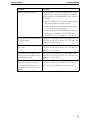
Print Quality Problems and Solutions
6-2
Paper Handling Problems and Solutions
6-4
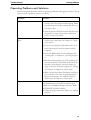
Operating Problems and Solutions
LED states in error conditions
6-5
6-6
Printer Failures
6-7
Diagnostic Functions
6-8
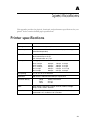
Chapter A
Specifications
A-1
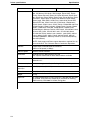
Printer specifications
A-1
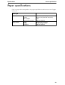
Paper specifications
A-4
Print Area
Continuous forms
Single sheets
A-5
A-5
A-6
Paper Thickness
A-7
Chapter B
Interfaces
B-1
Parallel interface
B-1
Parallel Interface Pin Assignment
B-2
B-2
IV
Compatible mode
B-3
Nibble mode
B-4
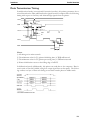
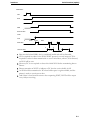
Data Transmission Timing
B-5
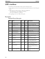
USB interface
B-6
Descriptor
Standard Device Descriptor
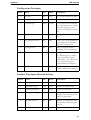
Configuration Descriptor
Interface Descriptor Alternate Setting
Endpoint 1 Descriptor
Endpoint 2 Descriptor
B-6
B-6
B-7
B-7
B-8
B-8
Table of contents
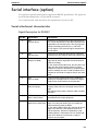
Serial interface (option)
B-9
Serial attachment characteristics
Signal Description for RS232C
Serial Interface Timings
Serial Interface Error Handling
Data rates
B-9
B-9
B-10
B-12
B-13
Configuring the serial interface of the PC
B-15
Auto Select Interface
B-16
Chapter C
Command Sets
C-1
9 wire printer
C-2
Printer basic functions
C-2
Emulation
Command list
Printer unique commands
C-3
C-3
C-9
24 wire printer
C-10
Printer basic functions
C-10
Emulation
Command list
Printer unique commands
C-11
C-11
C-17
Barcodes
C-20
IBM mode
Available barcode types
C-20
C-20
Epson mode
Available barcode types
C-20
C-20
Chapter D
Character Sets
D-1
IBM Proprinter Emulation
IBM Set 1 and 2
D-2
D-2
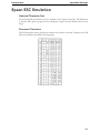
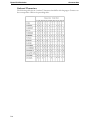
Epson ESC Emulation
National Character Sets
Common Characters
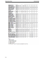
National Characters
D-3
D-3
D-3
D-4
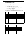
Restriction of fonts
D-5
9 wire printer
D-5
V
Table of contents
24 wire printer
Non scalable fonts
Scalable Fonts and Code Pages
Chapter E
Supplies and Options
VI
D-7
D-7
D-9
E-1
Supplies
E-1
Options
E-1
Interface Modules
E-2
1
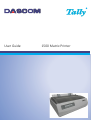
Introduction
Congratulations on purchasing the Matrix Printer Tally Dascom 1500. The printer is equipped
with a small printhead, which allows printing in draft mode and letter quality.
The printer lends itself to a wide range of applications, accepting a variety of data from
host computers. It caters to word processing functions with the high print quality and image processing with its ability to print bit image graphics.
1-1
Introduction
Features
Features
Key printer features and options are listed in the next two sections.
• Software compatibility. The printer operates with EPSON ESC/P2, IBM
Proprinter X(L)24e emulations. For both emulations are OKI superset commands
available.
• Various character sets. For IBM Mode: IBM Set 1 and Set 2. For EPSON Mode: 15
National Character Sets.
• Multiple fonts. The printer has eleven resident fonts: Draft, Roman, Sans Serif,
Courier, OCR-B, OCR-A, Prestige, Script, Orator, Gothic, Souvenir.
• High-speed printing. The print speed is up to 500 characters per second.
• Memory. The printer is equipped with ROM and RAM memory: 16 MBit of ROM
memory and 256 Kbytes of receiving buffer are available for storing input data and
downloading custom fonts.
• Simple switching of paper types. The ability to “park” continuous forms to switch
between continuous forms and single sheets.
• Automatic tear-off advancing. With factory settings of the Set-Up mode, continuous
forms’ perforations are automatically advanced up to the tear bar at the end of each job
so that forms can be torn off.
• Maintenance-free. The printer only requires periodic cleaning and changing of the ribbon cartridge.
1-2
Introduction
Symbols used
Important information is highlighted in this manual by three symbols.
NOTE: A note is a tip or extra information that may be helpful in installing or using the printer.
CAUTION: A caution message provides information that may help you
avoid equipment damage, process failure, or inconvenience. Read all
caution messages carefully.
STOP
WARNING: A warning message indicates the possibility of personal injury
if a specific procedure is not performed exactly as described in the guide.
Pay close attention to these sections and read them fully to prevent possible
injury.
1-3
Introduction
Important safety instructions
Important safety instructions
Read the following instructions thoroughly before starting up your printer in order to prevent injuries and avoid damage to the device.
• Place the printer on a solid and even base so that it cannot fall down to the ground.
• Do not expose the printer to high temperatures or direct sunlight.
• Keep all liquids away from the printer.
• Protect the printer from shock, impact and vibration.
• Be sure to connect the printer to a socket with the correct mains voltage.
• Always disconnect the system from the mains before opening the device to perform
maintenance work or remedy errors.
• Do not perform any operation or action in any way other than provided in this manual.
When in doubt, contact your dealer or service company.
• Keep in mind that hazard warnings in this manual or on the printer cannot cover every
possible case, as it is impossible to predict and evaluate all circumstances beforehand.
Be alert and use your common sense.
Safety Precautions
This printer is available in two models, the 110 V model and the 230 V model. The specifications that apply to your printer depend on your machine configuration. To prevent
fire or shock hazards, connect the power plug only to a properly rated power outlet.
1-4
2
Operating the printer
Overview
This chapter explains how to operate the printer. Topics covered are:
• Setting up your printer
• Getting to know the printer’s major parts and the control panel
• Selecting paper
• Overview of paper operations
• Adjusting for paper thickness
• Using continuous forms
• Using single sheets
• Feeding and positioning paper
• Switching paper types
2-1
Setting up your printer
Operating the printer
Setting up your printer
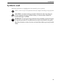
Unpacking the printer
Place your packaged printer on a solid base.
Make sure that the “Up” symbols point in the correct direction.
Open the packaging, lift the printer out of the cardboard box and remove the remaining
packaging material.
Check the printer for any visible transport damage and missing items. The following items
should be included:
Ribbon cassette
Power cord
Printer
Quick Start Guide and CD-ROM
If you find any transport damage or if any accessories are missing, please contact your
dealer.
2-2
Operating the printer
Setting up your printer
Placing the printer
Place the printer on a solid, flat, surface, ensuring that the printer is positioned in such a
way that it can not topple, and that there is easy access to the control panel and paper input
devices.
Also ensure that there is enough space for sufficient ventilation and for the printed output.
When selecting the printer location, observe the following additional instructions:
STOP
Never place the printer in the vicinity of inflammable gas or explosive
substances.
• Do not expose the printer to direct sunlight. If you cannot avoid placing the printer near
a window, protect it from the sunlight with a curtain.
• When connecting a computer to the printer, make sure not to exceed the maximum
cable length (see “Interfaces” on page B-1).
• Ensure sufficient distance between the printer and any heating devices/radiators.
• Avoid exposing the printer to extreme temperature or air humidity fluctuations. Above
all take care to avoid the influence of dust.
• It is recommended to install the printer in a place which is acoustically isolated from the
workplace because of the noise it may produce.
2-3
Setting up your printer
Operating the printer
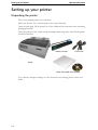
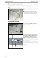
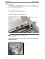
Installation procedure
Tape
When the printer is first taken out of the
packaging box, the cover of the printer is
taped as shown in the diagram. Remove
the tape.
Open the cover of the printer and
remove the shipping locks.
Keep the packaging for future transportation.
2-4
Operating the printer
Setting up your printer
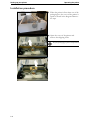
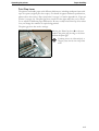
Installing the ribbon cassette
Proceed as follows to install the ribbon cassette.
Only use ribbon cassettes from the manufacturer as products from other manufacturers may damage
the printhead or the ribbon drive.
Remove the ribbon cassette from its
packaging.
Open the printer cover.
Adjust the printhead to the center of the
print roller.
Turn the tension knob A in the direction
of the arrow in order to take up slack of
the ribbon.
A
2-5
Setting up your printer
Operating the printer
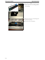
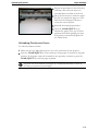
Insert the recess B on the bottom of the
ribbon cassette into the holding pin C of
the mounting.
B
C
Push the cassette into its mounting until
it clicks into position.
Close the cover of the printer.
2-6
Operating the printer
Setting up your printer
Connecting the printer
Checking the printer voltage
Make sure that the device has been set to the correct voltage (e.g. 120 V in the USA, 230 V
in Europe). To do this, check the type plate at the back of the printer. Contact your dealer
if the setting is incorrect.
Never switch on the printer if the voltage setting is incorrect, since this may
result in severe damage.
Connecting the mains power
Make sure that the power switch A,
located at the right side of the printer, is
position.
in the
A
Connect the power cable to the power
inlet of the printer. Connect the power
cable plug to a mains socket.
2-7
Setting up your printer
Operating the printer
Connecting the interface cable
The printer by default is provided with a parallel Centronics interface and an USB interface. For further information about the interfaces, refer to Appendix B, “Interfaces” on
page B-1.
Make sure that the printer and the computer are switched off.
Connect the data cable between the
printer and the computer, in this example a 36-pin centronics parallel cable.
Switching on the printer
Press the power switch A of the printer.
The printer initializes.
A
When the initialization is completed, the
Power indicator A and the Ready indicator
(SEL) B light up. If no paper has been
loaded, the Alarm indicator C also lights.
For more information on indicators, please
refer to the section “Operations of the Control
Panel” on page 2-12.
After loading paper, the printer is in the
online status and ready to accept data from
the system.
B
A
2-8
C
Operating the printer
Printer components
Printer components
This section describes the major parts and controls of the printer and operations of the
control panel. Take a moment to become familiar with the printer.
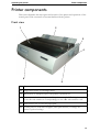
Front view
2
1
3
4
6
5
1
Cover
2
Single sheet feeder: to load single sheets.
3
Platen knob: to transport paper if the printer is powered off.
4
Power switch: Switches the power of the printer on and off. Pushing the switch
to the <I> side switches it on and pushing it to the <O> side switches it off.
5
Paper select lever: to select the paper path.
6
Control panel: to load and feed paper, select print features, or change the
printer’s optional settings.
2-9
Printer components
Operating the printer
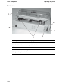
Rear view
1
2
5
3
4
2-10
1
Paper select lever: to select the paper path
2
USB interface: connect the USB cable here
3
Parallel interface: connect the parallel cable here
4
Tractor: to hold and feed continuous forms
5
Power inlet: Connect the power cord here
6
Space for optional interface
6
Operating the printer
Printer components
Internal view
1
2
3
1
Printhead
2
Paper thickness lever: to adjust the print gap for different paper thicknesses.
3
Ribbon cassette
2-11
Operations of the Control Panel
Operating the printer
Operations of the Control Panel
This section summarizes status indications and operations of the control panel in Normal
mode. For details on Set-Up mode, see Chapter 4, “Special mode” on page 4-1.
Tear Off
Draft
Draft Condensed
Tear Off
Roman
Sans Serif
Prestige
Font
Courier
Script
Others
Power /
Paper Out
LF/FF
Load/Eject
Micro Down
Micro Up
Online
Online
3 sec
Panel Layout
Normal mode operation includes everyday operations, such as paper handling, font and
character pitch selection.
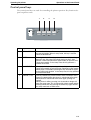
LED indicators
The LED lights of the control panel indicate the current status of the printer.
1
Tear Off
3
Draft
Draft Condensed
Tear Off
Roman
Sans Serif
Prestige
Font
Courier
Script
Others
Power /
Paper Out
LF/FF
Load/Eject
Micro Down
Micro Up
Online
Online
3 sec
2
No.
LED
Status
1 POWER
On: the printer is switched on. Off: the printer is switched off.
PAPER OUT Flashing: Paper out.
Flashing + buzzer: Paper jam
2-12
2 ON LINE
On: the printer is in Online mode and ready to receive data from the
computer.
Off: the printer is in Offline mode and cannot receive data.
3 TEAR OFF
FONT
When online, this key will move any loaded continuous paper to the tearoff position. When in setup state, this key is used to select the desired
font.
Operating the printer
Operations of the Control Panel
Control panel keys
The control panel keys are used for controlling the printer operation. Key functions depend on printer status.
1
2
3
4
LF/FF
Load/Eject
Online
Micro Down
Micro Up
Tear Off
Draft
Draft Condensed
Tear Off
Roman
Sans Serif
Prestige
Font
Courier
Script
Others
No.
Key
Power /
Paper Out
Online
3 sec
Function
1
TEAR OFF/FONT When online, this key will move any loaded continuous paper to
the tear-off position. When in setup state, this key is used to
select the desired font.
2
LF/FF
Pressing this key will feed paper one line forward. By holding
down this key, the printer will initially feed a few lines, then
perform a form feed (continuous paper mode) or eject the form
(single sheet mode). In the setup state, this key performs a
reverse micro feed.
3
LOAD/EJECT
When paper is loaded, pressing this key will eject the paper
(single sheet mode) or park the paper (continuous paper mode).
When paper is not loaded, pressing this key will load the paper
to the starting print position. In the setup state, this key performs
a forward micro feed.
4
ONLINE / 3 sec
This key switches the printer between online and offline states.
Printing is stopped when the printer is switched to offline state.
When printer is switched to online state again, printing will
resume.
When printer is offline, pressing it for 3 seconds or longer will
enter the setup state. This is indicated by a beep sound and the
flashing Online LED. By pressing the Online key again will exit
the setup state back to offline state.
2-13
Operations of the Control Panel
Operating the printer
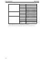
Font selection
The printer can print with different fonts. The actual selected font type is displayed by its
respective LED light.
If you want to change the font setting, press the TEAR OFF / Font key repeatedly
until the desired font type is set.
The following fonts are available:
2-14
Font selection label
LED 1 state
LED 2 state
Draft
Off
Off
Draft condensed
Off
Flash
Roman
Off
On
SanSerif
On
Off
Prestige
On
On
Courier
On
Flash
Script
Flash
Off
Others
Flash
On
Operating the printer
Paper handling
Paper handling
Paper types
The printer can handle either single sheets or continuous forms. Single sheets, also called
cut sheets, include envelopes and non-continuous, multipart forms. Continuous forms include labels and multipart forms fed into the printer using the forms tractors.
For best results, use paper that meets the specifications listed in the following table. (See
Appendix A, “Paper specifications” on page A-4 for detailed specifications.) If you are unsure
of the suitability of a particular type of paper, try testing the paper or consult your dealer.
Paper Specifications
Paper Size
Width -- Cut Sheet
102 to 267 mm (4 to 10,5“)
Width -- Fanfold
102 to 267 mm (4 to 10,5“)
Length
102 up to 559 mm (4 to 22“)
Thickness
Up to 0.35 mm (0,014“)
Paper Thickness and Number of Copies
Thickness
0.35 mm (0.014 in) maximum total thickness.
Copies
1 to 4 copies, including the original. For carbon-inter-leaved paper,
the carbon counts as a copy.
2-15
Paper handling
Operating the printer
Loading paper
Your printer can process both fanfold paper and single sheets. For information on the
supported paper sizes, please refer to the section “Paper types” on page 2-15 and to Appendix A, “Paper specifications” on page A-4.
Overview of Paper Operations
The following levers are used in paper handling.
• Print Gap lever A on the right side under the cover.
• Paper Select lever B on the right side of the cover.
B
A
To load or feed paper, the printer must be:
– In Online mode but not receiving or printing data
– In Offline mode.
Paper select lever
The paper select lever is used to select the paper path.
Move the paper select lever A backward
for single sheets.
Move the paper select lever forward for
continuous sheets.
A
2-16
Operating the printer
Paper handling
Print Gap Lever
The printer can handle paper with different thicknesses, including multipart forms with
up to five parts (original plus four copies). For details on paper thickness specifications,
please refer to the section “Paper Specifications” on page 2-15 and to Appendix A, “Paper specifications” on page A-4. The print gap lever, located on the right under the cover, allows
you to adjust for different paper thicknesses. Be sure to adjust the Print Gap lever whenever you change the number of copies being printed.
The print gap lever has twelve settings.
A
–
Moving the Print Gap lever A to the rear
reduces the print gap, moving to the front
widens the print gap.
If printing smears, the ribbon misfeeds, or
the paper jams, move the lever one position
wider.
+
2-17
Paper handling
Operating the printer
Fanfold paper
Move the paper select lever forward to
continuous paper position.
If necessary, readjust the Print Gap
lever for continuous forms (see section
“Print Gap Lever” on page 2-17).
Slightly press the single sheet feeder to
the right or to the left, until the holding
pin comes free from its recess. Remove
the feeder.
Release the tractor locking levers A by
pulling them up. Once the right forms
tractor is positioned, lock it by pulling
up its locking lever.
A
Raise the tractor doors and fit the first
two paper feed holes onto the right
tractor pins. Close the right tractor
door.
2-18
Operating the printer
Paper handling
Repeat the procedure for the left tractor
and adjust the left forms tractor to
accommodate the width of the form.
Move the left tractor to make the paper
flat. Do not stretch the paper too taut.
Push the left locking lever down to
secure the tractor in place.
Reinstall the manual paper feeder.
Press the LOAD/EJECT key to
advance the paper to the top-of-form
position from which printing can start.
The printer is automatically placed in
the Online State.
Unloading Continuous Forms
To unload continuous forms:
Make sure that the Paper Select lever is set to the continuous forms position.
Press the LOAD/EJECT key. The continuous forms paper is retracted to the park
position. If the paper cannot be retracted in one operation, continue to press the
LOAD/EJECT key until the paper is parked.
The printer can retract continuous forms-paper by a recommended maximum of 30.48 cm
(12 inches) per operation (one form length).
2-19
Paper handling
Operating the printer
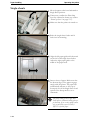
Single sheets
Move the paper select lever backward to
Single Sheet position.
If necessary, readjust the Print Gap
lever for continuous forms (see section
“Print Gap Lever” on page 2-17).
Make sure that the printer is turned on.
Raise the single sheet feeder until it
locks into its mounting.
Align the left paper guide with the mark
on the left of the single sheet feeder.
Adjust the right paper guide to the
width of the paper used.
Insert a sheet of paper. Make sure that
the bottom edge of the paper engages
snugly with the platen. The paper will
automatically advance to the top-ofform posi-tion if the Single Sheet Load
option of the Setup mode is set to
Automatic.
The factory setting for the Single Sheet
Load option is automatic loading after paper detection. If you set this option to manual, you will have to press LOAD /
EJECT to feed the paper.
2-20
Operating the printer
Paper handling
Ejecting Single Sheets
If you print using software which inserts a form feed at the end of each page, each sheet
is ejected automatically upon the completion of the page printing.
To manually eject sheets of paper: Press the LOAD/EJECT key to execute a forward
form feed.
2-21
Paper handling
Operating the printer
Paper Parking Function
Switching from fanfold paper to single sheets
When using fanfold paper (push tractor), single sheets can be inserted without removing
paper from the tractor feeder.
The fanfold paper can be moved to the parking position by the switches on the operation
panel. Switching to friction feed after doing this allows printing on single sheets with the
fanfold paper in the tractor feeder left as it is.
To switch from fanfold paper to single sheet mode proceed as follows:
Tear off printed paper at its perforation, if necessary.
Press the LOAD/EJECT key. The fanfold paper is transported backward to the park
position.
Move the paper select lever backward to Single Sheet position.
If necessary, readjust the Print Gap lever for continuous forms (see section “Print Gap
Lever” on page 2-17.
Raise the single sheet feeder until it locks in its mounting.
Align the left paper guide with the mark on the left of the single sheet feeder. Adjust
the right paper guide to the width of the paper used.
Insert a sheet of paper. Make sure that the bottom edge of the paper engages snugly
with the platen. The paper will automatically advance to the top-of-form position if
the Single Sheet Load option of the Setup mode is set to Automatic.
Switching from single sheets to fanfold paper
To switch from single sheet mode to tractor mode, proceed as follows:
If a single sheet is loaded, press the LOAD/EJECT key. The sheet is ejected.
Move the paper select lever to the front (user’s direction) to Continuous Paper
position.
Press the LOAD/EJECT key again. The printer feeds the fanfold paper to the top
of form position.
2-22
Operating the printer
Paper handling
Feeding and Positioning Paper
Print Area Definition
• Top-of-Form: This value defines the distance between the edge of the paper and the
place where you allow the printing to begin (position of line number 1). You can adjust
this distance according to the condition of your paper (for example, pre-printed forms).
When you load the paper, the printer feeds the paper to this position, waiting for printing commands.
• Form Length: Set the corresponding Page Set-Up option (FANFOLD FORM
LENGTH / SINGLE FORM LENGHT) according to the actual physical page length
(distance between two perforations for continuous forms). This will allow the printer
to know exactly where the printhead is and to position it at the same position when a
form feed occurs.
• Top Margin: This is the line where the printing actually starts. To define a top margin,
select the position of this line within Adjust Page Margins mode (TOP MARGIN
option). Example: In the following picture, TOP MRGN option is set to 3/72 inch.
• Left Margin: This is the margin where the left printing actually starts. To define a left
margin, select the number of this margin within Adjust Page Margins mode (LEFT
MARGIN option).
Example: In the following picture, BOTTOM MARGIN option is set to 147/42 inch.
• Print area: Print area defined by the corresponding Set-Up options: Form Length, Topof-Form, Top Margin, and Bottom Margin.
• Paper perforation: The perforation defines the physical page length.
2-23
Paper handling
Operating the printer
Continuous forms
(When printed with the top of the dot head)
6.35
E
D
B
Print Area
12.7 ± 0.1
C
F
6.35
6.35
6.35 ± 0.3
A
2-24
Symbol
Dimensions
Remark
A
76.2 ~ 254
Paper width
B
~ 355.6 (Perforation)
150 ~ 355.6 (Fold)
Paper length
C
6.35 (min)
D
6.35 (min)
The recommended distance is to be 12mm
Or more in actual operation to avoid
Print blurs and stains affected by
The sprocket hole or the vertical perforation.
E
6.35
This distance is recommended in order to
Avoid print blurs and print pitch disorder
Affected by the horizontal perforation.
F
9.6
Same as E, however paper feed precision
Of the last page is not guaranteed.
Operating the printer
Paper handling
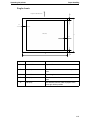
Single sheets
D
Paper Feed Direction
E
C
Print Area
E
B
A
Symbol
Dimensions
Remark
A
76.2 ~ 297.2
Paper width
B
9.6 (min)
The distance from the rear end to the printable
area
C
76.2 ~ 558.8
Paper length
D
6.35 (min)
The distance from the front end to the printable
area
E
6.35 (min)
The distance from the sides of papers to the
most right left dot position
2-25
Paper handling
Operating the printer
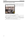
Setting the first printing line (TOF)
You can use the TOF function for setting the vertical position of the first printing line.
A
The mark A on the transparent paper protective cover of the printhead can be helpful if you want to adjust the first printing
line.
To adjust the first printing line vertically, proceed as follows:
Either transport fanfold paper to the next top of form position or feed an inserted
single sheet by pressing the LOAD/EJECT key.
Make sure that the printer is in offline mode; press the ONLINE key, if necessary.
Hold the ONLINE key depressed for 3 seconds, and use the Micro Feed Down or
Micro Feed Up keys to adjust the desired first printing line. Each micro feed will
feed the paper down or up in 1/180 inch increments.
After releasing the key, the new adjusted first printing line is saved.
2-26
Operating the printer
Paper handling
Selecting Tear-off mode
By default the “Tear” parameter of the printer is set to “Manual”. If you want to transport
the paper to tear-off position, you must press the TEAR OFF key.
The “Tear” parameter can be set to automatic mode. In this case the paper is transported
after a certain duration of time (1, 2, 3, 4 or 5 seconds) automatically to the tear-off position if the printer does not receive data.
When the printer receives the next print request, the paper moves automatically from the
tear-off position to the previous position.
Proceed as follows to select an automatic tear-off mode:
Make sure that continous paper is loaded and the printer is in offline mode. Press the
ONLINE key if necessary.
Hold the SHIFT key depressed and press the MENU key.
After releasing the keys, the MENU indicator lights up, indicating that the printer has
entered the setup mode.
Button
Set-Up Action
1
PARK
TEAR
FF/LOAD
LF
SEL
Move cursor Down to the next Function or Value
Move cursor Up to the next Function or Value
Select the Option or Value and Move cursor Right
Select the Option or Value and Move cursor Left
Select the Option or value and Move to SAVE&EXIT
2
<FUNCTIONS>
PRINTER CONTROL
} The initial printout contains a header, help menu (1), and <FUNCTIONS> menu (2).
The header tells you that the printer is in the setup mode. The help menu provides a
quick summary of how to use keys in the setup mode.
The <FUNCTIONS> menu 2 is started from PRINTER CONTROL.
Press the PARK/PRINT/q key five times.
<FUNCTIONS>
PRINTER CONTROL
FONT
SYMBOL SETS
SET UP
INTERFACE
COMMON (PUSHTRAC)
} You have now reached the pushtractor parameter group: COMMON (PUSH-
TRAC).
2-27
Paper handling
Operating the printer
Press the FF/LOAD/Micro Feed Up/u key to select the parameter group.
Press the PARK/PRINT/q six times.
} You have now reached the TEAR parameter.
<FUNCTIONS>
PRINTER CONTROL
FONT
SYMBOL SETS
SET UP
INTERFACE
COMMON (PUSHTRAC)
<PAPER SET>
<LPI>
<TOP MARGIN>
<BOTTOM MARGIN>
<FORM LENGTH>
<CENTERING>
<TEAR>
Press the FF/LOAD/Micro Feed Up/u key to select the parameter.
} The current value is printed, MANUAL in our example.
Repeatedly press the FF/LOAD/Micro Feed Up/u key to position the desired
value, e.g. AUTO 1 SEC.
<PAPER SET>
<LPI>
<TOP MARGIN>
<BOTTOM MARGIN>
<FORM LENGTH>
<CENTERING>
<TEAR>
MANUAL
AUTO 1 SEC
Press the SEL/MENU key to select the desired value and to activate the
SAVE&EXIT position.
Press the SEL/MENU key again to save the new value and exit the setup mode.
} The printer exits the setup mode and returns to the ready mode. The selected values
remain in effect until the next time they are changed.
2-28
Operating the printer
Paper handling
Using the tractor as pull tractor
By default the tractor of your printer is mounted at the rear and works as push tractor.
You can use the tractor as pull tractor also. Because the paperway is more straight in pull
mode this may be useful if you want to print critical paper types.
This section describes how to remove the push tractor and install it as pull tractor.
Open the printer cover.
Slightly press the single sheet feeder to
the right or to the left, until the holding
pin comes free from its recess. Remove
the feeder.
Press the two hooks A and remove
cover B.
B
A
C
C
Press the two levers C upward and
remove the tractor.
2-29
Paper handling
Operating the printer
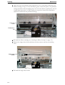
Insert the two holding pins D of the
tractor into the recesses of the mountings.
D
Press the two levers C into your direction, move the tractor backward until
the two pins E engage into the recesses
of the tractor and release the levers.
C
E
Close the cover of the printer.
If you switch the printer on again, it autmatically detects that the pull tractor is installed.
You can now feed continous paper from the slot in the bottom of the printer.
After loading paper into the tractor, you must carry out a form feed. For this reason you cannot
print on the first form.
2-30
3
Printing
This chapter describes the following typical printing operations:
• Starting, stopping, or resuming printing and viewing last printed lines.
• Removing printed pages.
The PARK/PRINT, FF/LOAD and the SEL/MENU keys are used for these operations, which are described in this section. For a summary of the operation of these keys,
see the section “Operations of the Control Panel” on page 2-12 in Chapter 2, “Operating the
printer” on page 2-1.
Instructions for loading and handling paper are also given in Chapter 2, “Operating the
printer”.
3-1
Starting or Stopping Printing
Printing
Starting or Stopping Printing
Starting Printing
Before you start to print, make sure that paper is loaded. Also, verify that the paper select
lever and the print gap lever are set to the appropriate position.
To start printing, make sure that the Ready indicator is lit (the printer is ready). If not so,
press the SEL/MENU key to place the printer in the Ready state. Start your print job.
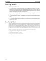
Stopping Printing
To stop printing, press the SEL/MENU key to place the printer in the Pause state. The
printer stops after printing the current line. You can also use your software to stop printing, but there will be a slight delay before printing stops. After the printer enters the Pause
state, it still receives data until the print buffer becomes full of new data.
The data in the print buffer will be lost if you turn the printer off.
Resuming Printing
To resume printing, press the SEL/MENU key again. To cancel printing, use the cancel
commands provided by your software or computer. To clear the print buffer, turn the
printer off.
Any data sent to the print buffer before you canceled printing will be lost.
Resuming from a Paper-Out
The printer can “sense” when paper runs out. The printer stops printing and lights the
ALARM indicator. To resume printing when paper runs out, follow the procedures
described below:
Install paper on the forms tractor unit or on the cut sheet feeder as described in
Chapter 2, “Operating the printer”.
To load the first sheet of paper, press the FF/LOAD key for continuous forms. Single sheets are automatically loaded unless you change the factory default setting. The
ALARM indicator will turn off and the printer resumes printing.
3-2
4
Special mode
Your Printer has two operation modes:
• The Normal mode is used for daily operations like paper handling and printing as explained in Chapter 2, “Operating the printer” and Chapter 3, “Printing”.
• The Special mode is used to change the printer settings and to test the printer functions.
The following table summarizes the purpose of each function.
Special Mode Functions
Function
Purpose
Set-Up Mode
Change the Printer settings.
Print Configuration
Print the Printer Configuration. To check your settings
by printing a list of all the printer’s currently selected
values.
Printing Test
Run the printing test.
Hex Dump Mode
Hex-dump allows you to determine whether the computer is sending the correct commands to the printer.
This is useful for troubleshooting.
Printing Alignment Adjustment
Perform adjustment Bi-directional alignment.
Top of Form Adjustment
Perform adjustment of Top of Form.
Setting of The First Dot Position on the left side
Change the left margin fine adjustment.
Menu Access
Restricts access to Set-Up functions from the control
panel.
Setting Set-Up Mode to Default
Value (Standard)
Resets factory settings to standard.
4-1
Set-Up mode
Special mode
Set-Up mode
The Set-Up mode allows you:
• To define a printer operating environment for your application software. The printer
operating environment includes the emulation, font, symbol sets, horizontal and vertical pitches, page length and margins, line mode, and printing direction. It also includes
emulation dependent options like the character set.
• To define general installation parameters related to the integration in your environment
(e.g., menu language, tear-off control, auto-load control, and interface).
• To recall all the factory settings (including the user environment and installation parameters).
• To define what kind of settings modifications are allowed to avoid accidentally changing of Set-Up values.
How Set-Up Works
The Set-Up mode consists of Set-Up function menus which correspond to several printer
settings. Each parameter group generally has many parameters which correspond to the
print features to be changed. Each parameter includes many values to be selected. All the
Set-Up function menus, parameters and values are printed in a logical sequence on the paper when you enter the Set-Up mode, including the usage of keys. You can perform all the
Set-Up operations by using keys on the control panel in the following order:
• Navigating through the option menu structure.
• Selecting a new value for an option.
• Saving your new printer configuration.
4-2
Special mode
Set-Up mode
Entering the Set-Up Mode
Proceed as follows to enter the Set-Up mode:
Make sure that continous paper is loaded and the printer is in offline mode. Press the
SEL/MENU key if necessary.
Hold the SHIFT key depressed and press the MENU key.
After releasing the keys, the MENU indicator lights up, indicating that the printer has
entered the Set-Up mode.
Button
Set-Up Action
1
PARK
TEAR
FF/LOAD
LF
SEL
Move cursor Down to the next Function or Value
Move cursor Up to the next Function or Value
Select the Option or Value and Move cursor Right
Select the Option or Value and Move cursor Left
Select the Option or value and Move to SAVE&EXIT
2
<FUNCTIONS>
PRINTER CONTROL
} The initial printout contains a header, help menu (1), and <FUNCTIONS> menu (2).
The header tells you that the printer is in the Set-Up mode. The help menu provides a
quick summary of how to use keys in the Set-Up mode.
The <FUNCTIONS> menu 2 is started from PRINTER CONTROL.
4-3
Set-Up mode
Special mode
Overview of the Set-Up Mode
Your Printer has eleven function menus in Set-Up mode.
When you press the PARK/PRINT/q key or the TEAR/p key, the following next or
previous <FUNCTIONS> menu is printed.
} PRINTER CONTROL
} FONT
} SYMBOL SETS
} SET-UP
} INTERFACE
} NETWORK
} COMMON (PUSH TRAC)
} PULL TRACTOR
} FRICTION
} RCALL-FACT
} SAVE&EXIT
The following table summarizes the purpose of each function.
4-4
Function
Description
PRINTER CONTROL
Changes the emulation (generally or by interface).
FONT
Selects the Font, the Draft mode (Normal or High Speed
Draft) and the character pitch.
SYMBOL SETS
Selects the IBM Set, code page (IBM), the character set
(Epson) and the style of the zero character (slashed/
unslashed).
SET-UP
Selects the print direction: unidirectional, bidirectional or
softcontrol printing. Specifies the effect of CR (Carriage
Return) and LF (Line Feed) codes. Selects timeout, language,
safe panel and the printhead impact.
INTERFACE
Changes settings for all interfaces.
NETWORK
Changes network settings of the integrated print server
(option).
COMMON (PUSH
TRAC)
Changes push tractor settings (e.g. line density, margins, tearoff function).
PULL TRACTOR
Changes pull tractor settings (e.g. line density, margins, tearoff function).
FRICTION
Changes settings for the single sheet mode (e.g. line density,
margins, load function).
RCALL-FACT
Resets all values of the Set-Up menu to the factory settings.
SAVE&EXIT
Saves the settings and exits Set-Up mode.
Special mode
Set-Up mode
To select a function from the <FUNCTIONS> menu:
Repeatedly press the PARK/PRINT/q key or the TEAR/p key to position the
function you require.
Press the FF/LOAD/Micro Feed Up/u key to select the function. The printer
prints the first parameter. Repeatedly press the PARK/PRINT/q key or the
TEAR/p key to position the option you require.
The first five PRINTER CONTROL parameters are shown below.
<FUNCTIONS>
PRINTER CONTROL
EMULATION
EMUL PARALLEL
EMUL USB
EMUL SERIAL
EMUL ETHERNET
Press the FF/LOAD/Micro Feed Up/u key to select the option. The printer prints
the first value. Repeatedly press the PARK/PRINT/q key or the TEAR/p key to
position the value you require.
The EMULATION values are shown below.
<FUNCTIONS>
PRINTER CONTROL
EMULATION
EPSON-EP
IBM XL
PORT DEPEND
If you leave the menu the last set item (e.g. PORT DEPEND) remains active and set.
4-5
Set-Up mode
Special mode
Options with Pre-determined Values
For some options, you can choose among a limited set of pre-determined values. To select such a value:
Repeatedly press the PARK/PRINT/q key or the TEAR/p key to position the
value you require.
Press the FF/LOAD/Micro Feed Up/u key to select the function. The printer
prints the first parameter.
Press the SEL/MENU key to select the desired value and to activate the
SAVE&EXIT position.
Press the SEL/MENU key again to save the new value and exit the Set-Up mode.
} The printer exits the Set-Up mode and returns to the ready mode. The selected values
remain in effect until the next time they are changed.
Example: Changing the Vertical Pitch
To become familiar with the Set-Up mode, try the following example. This example shows
how to change the vertical pitch in COMMON (PUSH TRAC) from 6 lines per inch to 8
lines per inch.
Enter the Set-Up mode: Turn the printer off and back on while pressing the SEL/
MENU key.
Select the COMMON (PUSH TRAC) function: Wait for the printer to stop printing and press the PARK/PRINT/q key five times to print the COMMON (PUSH
TRAC) function.
Press the FF/LOAD/Micro Feed Up/u key to print the PAPER SET parameter.
Press the PARK/PRINT/q key to print the LPI parameter.
Press the FF/LOAD/Micro Feed Up/u key to print the current LPI value (default:
6 LPI).
Change the vertical pitch from 6 to 8 lines per inch. Press the PARK/PRINT/q
key once to position the 8 LPI. Press the SEL/MENU key to select 8 LPI.
Press the SEL/MENU key to select 8 LPI and to activate the SAVE&EXIT position.
Press the SEL/MENU key again to save the new value and exit the Set-Up mode
and return to the Ready state. This setting remain in effect until the next time they are
changed.
4-6
Special mode
Set-Up mode
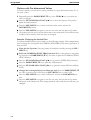
Options with Undetermined Values
For top and bottom margin parameters, you can choose among a continuous range of
values.
Example: Changing the Top Margin of the Single Sheet Feeder
This example shows how to change the top margin of the single sheet feeder from 0/
72 inch to 3/72 inch.
Enter the Set-Up mode: Turn the printer off and back on while pressing the SEL/
MENU key.
Select the FRICTION function: Wait for the printer to stop printing and press the
PARK/PRINT/q key seven times to select the FRICTION function.
Press the FF/LOAD/Micro Feed Up/u key to print the LPI parameter.
Press the PARK/PRINT/q key to print the TOP MARGIN parameter.
Press the FF/LOAD/Micro Feed Up/u key to print the current top margin value.
Repeatedley press the PARK/PRINT/q or the TEAR/p key until the desired
value is printed.
Press the SEL/MENU key to select the desired value and to activate the
SAVE&EXIT position.
Press the SEL/MENU key again to save the new value and exit the Set-Up mode
and return to the Ready state. These setting remain in effect until the next time they
are changed.
Points to Remember
} We recommend that you use continuous forms paper for printing in the Set-Up mode
because the output will exceed a single page.
} Whenever you enter the Set-Up mode, short help menus are printed at the top of the
page. Use the help menus for quick reference while in the Set-Up mode.
} When printing the option for each function, you can move either forward or backward
in the option list. To move forward (print the next option), press the PARK/PRINT/
q key. To move backward (print the previous option), press the TEAR/p key.
} While in the <FUNCTIONS> menu or when selecting a function that contains op-
tions and selectable values, press the SEL/MENU key to reprint the
<FUNCTIONS> menu SAVE&EXIT.
4-7
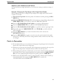
Set-Up mode
Special mode
Functions, parameters and values
The following section introduces and explains all the possible menu settings. Please note
that some settings are overridden by commands from the computer.
Values in bold are the factory settings.
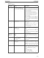
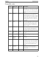
PRINTER CONTROL menu
4-8
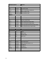
Parameter
Value
Description
EMULATION
EPSON-EP2
IBM XL24E
PORT DEPEND
Selects the same emulation as that
selected by your software.
PORT DEPEND: The printer selects
emulation according to the active interface (such as serial, USB). See the next
options.
EMUL PARALLEL
EPSON-EP2
IBM XL24E
Selects an emulation for the Parallel
interface. This is invalid and skipped
when PORT DEPEND is not selected
for the EMULATION option.
EMUL USB
EPSON-EP2
IBM XL24E
Selects an emulation for the USB interface. This is invalid and skipped when
PORT DEPEND is not selected for the
EMULATION option.
EMUL SERIAL
EPSON-EP2
IBM XL24E
Selects an emulation for the optional
Serial interface. This is invalid and
skipped when PORT DEPEND is not
selected for the EMULATION option.
EMUL ETHERNET EPSON-EP2
IBM XL24E
Selects an emulation for the optional
Ethernet interface. This is invalid and
skipped when PORT DEPEND is not
selected for the EMULATION option.
IBM AGM
Selects the IBM graphic mode (AGM =
Advanced Graphics Mode).
NO
YES
Special mode
Set-Up mode
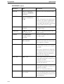
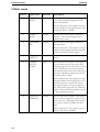
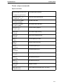
FONT menu
Parameter
Value
Description
FONT
DRAFT, ROMAN,
SANS SERIF, COURIER,
OCR-B, OCR-A, PRESTIGE, SCRIPT, ORATOR,
GOTHIC, SOUVENIR
Selects a font to be active when the
power is turned on. For fixed-spaced
fonts, be sure to change the horizontal
pitch as well.
Draft font: lower resolution than letter
quality, 3 times the speed of the other
fonts which are printed in letter quality
DRAFT FONT NORMAL DRAFT
Selects if the Draft font is printed as
Normal Draft.
CPI
Selects the characters per horizontal
inch.
10CPI/12CPI/15CPI/
17CPI/20CPI
4-9
Set-Up mode
Special mode
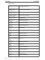
SYMBOL SETS menu
Parameter
Value
Description
IBM SET 1/2
IBM SET1
IBM SET2
CRO-ASCII, Arabic Farsi,
Arabic Urdo, Greek DEC,
Greek ELOT 928, CP
437, CP 737, CP 850, CP 851,
CP 852, CP 857, CP 858, CP
860, CP 861, CP 863, CP 864,
CP 864 Extended, CP 865,
CP 866 Cyrillic, CP 866 Bulgaria, CP 1250, CP 1251, CP
1252, CP 1253, CP 1254,
8859-1, 8859-1(SAP), 8859-2,
8859-5, 8859-7, 8859-9, 885915, BRASCII, Abicomp,
Roman8, Coax/Twinax,
New-437, New-DIG 850,
Old-Code 860, Flarro 863,
Table 865
Selects if IBM character set 1 (normal)
or 2 (extended) is active.
Selects the national code page (for the
IBM emulation only).
E-CHR SET
USA/FRANCE/GERMANY/UK/DENMARK/
SWEDEN/ITALY/SPAIN/
JAPAN/NORWAY/ DENMARK II/ SPAIN II/
LATIN AM/KOREA/
LEGAL
Selects a national character set (Epson
emulation only).
ZERO
CHARACTER
SLASHED
UNSLASHED
Selects if normal zero (0) or the slashed
zero (Ø) is printed.
CODE PAGE
4-10
Special mode
Set-Up mode
SET-UP menu
Parameter
Value
Description
PRINT DIR
UNIDIR/UNIDIR(G)/
BIDIR/SOFT CONTROL
Unidirectional printing is used for printing that needs precise vertical alignment.
Unidirectional printing is slower than bidirectional printing.
Bi-directional printing: The printer
prints in either direction while seeking
the next print direction for a shorter
print time. The unidirectional command is ignored.
SOFT CONTROL: The print direction
follows a command from the computer.
If no command is sent, print direction is
bi-directional.
CR CODE
CR=CR
CR=LF+CR
Specify the effect of CR (Carriage
Return) code.
CR=CR: No line feed is added to a carriage return
CR=LF+CR: A line feed is added to
each carriage return.
LF CODE
LF=LF
LF=LF+CR
Specify the effect of LF (Line Feed)
code.
LF=LF: No carriage return is added to a
line feed.
LF=LF+CR: A carriage return is added
to each line feed.
TIME OUT
PRINT
NO
YES
Prints out the data in the buffer after a
short time, even without a print command.
LANGUAGE
ENGLISH/GERMAN/
SPAIN/FRENCH/
ITALIAN
Specifies a language to be used to print
the Set-Up menu functions and options
(status page).
SAFE PANEL
NO
LIMITED
If the parameter LIMITED is selected,
the access to Set-Up menu is restricted.
NOTE: For more information refer to
the section “Menu access” on page 4-28.
IMPACT
1/2/3/4/5/6/7/8
Selects the impact strength of the printhead (1 = light). This ensures that single
or copy paper produces optimum
results.
6: for single-ply paper.
7: for 2- or 3-ply paper
8: for 4-ply paper and above
4-11
Set-Up mode
Special mode
INTERFACE menu
4-12
Parameter
Value
Description
BUFFER
2KBYTE/16KBYTE/
64KBYTE/128KBYTE/
256KBYTE
Selects the size of the interface buffer.
I/F TYPE
PARALLEL/USB/
SERIAL/ETHERNET/
AUTO
Selects the type of interface to the computer.
AUTO: All interfaces are ready for communication. The printer communicates
with the interface from which it first
receives data. The interface is active until
the input buffer becomes empty.
PAPER EMPTY
OFFLINE
ONLINE
Sets printer to offline or online mode
after paper empty.
PARALLEL
NIBBLE/UNI DIR/
M307/TGNet III
Selects the transmission mode of the
parallel interface.
I-PRIME
BUFFER PRINT/
BUFFER CLEAR/
INVALID
Behavior of the printer after receiving an
Init/Prime signal.
BAUD RATE
4800 BPS/9600 BPS/19200 The baud rate is in bits per second.
BPS/38400 BPS
Select the same baud rate as that used by
your computer or modem.
PARITY
NONE/EVEN/ODD
Parity setting; select the same word parity setting that is used by your computer
or modem.
None causes transmission in both directions without parity bit. Even: The bytes
are checked to ensure they have even
parity. Odd: The bytes are checked to
ensure they have odd parity.
DATA BIT
8 BIT/7 BIT
Word Length setting; select the same
word length setting that is used by your
computer or modem.
8 bit: 8 Data bits per data byte. 7 bit: 7
Data bits per data byte.
STOP BIT
1/2
Word Length setting; select the same
word length setting that is used by your
computer or modem.
Selcts 1 or 2 stop bit per data byte.
PROTOCOL
READY/BUSY
XON/XOFF
Selects the type of protocol, i.e. a certain
set of rules and procedures for ensuring
error-free data exchanges between computer and printer.
Special mode
Set-Up mode
Parameter
Value
Description
BUSY LINE
DTR/RTS/SSD+/SSD-
Selects the signal indicating that the
serial interface is in busy state (buffer is
full, printer is out of paper or an error is
detected). Valid only if the READY/
BUSY protocol has been selected.
DSR SIGNAL
VALID/INVALID
Sets the signal DSR (Data Set Ready)
valid or invalid.
DTR SIGNAL
POWER UP/READY ON DTR is either set constantly to on
(power up) or is used for handshaking
(ready on).
BUSY TIME
200 ms/1 sec
Selects the busy time of the serial interface.
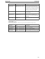
NETWORK menu
The following settings are valid for the optional internal Ethernet adapter only.
Parameter
Value
Description
IP ADDRESS
0,0,0,0 ... 255,255,255,255
Selects the IP address.
GATEWAY
0,0,0,0 ... 255,255,255,255
Selects the Gateway address.
NET MASK
0,0,0,0 ... 255,255,255,255
Selects the address of the Subnet mask.
4-13
Set-Up mode
Special mode
COMMON (PUSH TRAC) menu
4-14
Parameter
Value
Description
PAPER SET
COMMON
FEED DEPEND
Apply paper properties to all
paperways or feed dependend.
LPI
1LPI/2LPI/3LPI/4LPI/5LPI Sets the line density in lines per
/6LPI/8LPI/12LPI
inch.
6LPI = 6 lines per inch.
TOP MARGIN
0/60INCH/1/60INCH
/…../119/60INCH/
120/60INCH
Specifies the position of the top
line in n/60 inch. See “Print Area
Definition” on page 2-25.
BOTTOM MARGIN 0/60INCH/1/60INCH
/…../29/60INCH/30/
60INCH
Specifies the position of the bottom line in n/60 inch. See “Print
Area Definition” on page 2-25.
RIGHT MARGIN
8 INCHES/13.6 INCHES
Specifies the print width of the
wide model.
FORM LENGTH
3 INCHES/3.5 INCHES/
4 INCHES/5.5 INCHES/
6 INCHES/7 INCHES/
8 INCHES/8.5 INCHES/
11 INCHES/
11 2/3 INCHES/
12 INCHES/14 INCHES/
17 INCHES
Specifies the length of the page in
inches. See “Print Area Definition”
on page 2-25.
CENTERING
MODE1
MODE2
Adjusts the position of the printhead to the used paper width.
This reduces and optimizes the
printhead movement.
Narrow printer: Select MODE1
for paper widths between 125 and
209 mm and widths narrower as
125 mm.
Wide printer: Select MODE1 for
paper widths narrower as
125 mm. Select MODE2 for
paper widths between 125 and
210 mm.
Special mode
Set-Up mode
Parameter
Value
Description
TEAR
AUTO 1 SEC/AUTO 2 SEC/ Specifies the (auto) start time of
AUTO 3 SEC/AUTO 4 SEC/ tear-off feeding. If e.g. AUTO 3
AUTO 5 SEC/MANUAL
SEC is selected, auto tear-off
feeding is executed 3 seconds
after data transmission from the
computer has ended. If MANUAL is selected, you have to feed
the paper in the tear-off position
manually.
PAPER INITIAL
NO
YES
4-15
Set-Up mode
Special mode
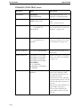
FRICTION menu
4-16
Parameter
Value
Description
LPI
1LPI/2LPI/3LPI/4LPI/5LPI Sets the line density in lines per
/6LPI/8LPI/12LPI
inch.
6LPI = 6 lines per inch.
TOP MARGIN
0/60INCH/1/60INCH
/…../119/60INCH/
120/60INCH
Specifies the position of the top
line in n/60 inch. See “Print Area
Definition” on page 2-25.
BOTTOM MARGIN 0/60INCH/1/60INCH
/…../29/60INCH/30/
60INCH
Specifies the position of the bottom line in n/60 inch. See “Print
Area Definition” on page 2-25.
RIGHT MARGIN
8 INCHES/13.6 INCHES
Specifies the print width of the
wide model.
FORM LENGTH
3 INCHES/3.5 INCHES/
4 INCHES/5.5 INCHES/
6 INCHES/7 INCHES/
8 INCHES/8.5 INCHES/
11 INCHES/
11 2/3 INCHES/
12 INCHES/14 INCHES/
17 INCHES
Specifies the length of the page in
inches. See “Print Area Definition”
on page 2-25.
CENTERING
MODE1
MODE2
Adjusts the position of the printhead to the used paper width.
This reduces and optimizes the
printhead movement.
Narrow prineter: Select MODE1
for paper widths between 125 and
209 mm and widths narrwoer as
125 mm.
Wide printer: Select MODE1 for
paper widths narrower as
125 mm. Select MODE2 for
paper widths between 125 and
210 mm.
MEDIA
FRICTION
CONTINUOUS
Selects the media type: single
sheets (FRICTION) or continuous forms (CONTINUOUS).
Special mode
Set-Up mode
Parameter
Value
Description
S-SHEET LD
AUTO 1 SEC/AUTO 2
SEC/AUTO 3 SEC/AUTO 4
SEC/AUTO 5 SEC/
MANUAL
Specifies the (auto) start time of
paper loading. If e.g. AUTO 3
SEC is selected, auto paper loading is executed 3 seconds after
inserting the paper. If MANUAL
is selected, you have to load the
paper manually.
4-17
Set-Up mode
Special mode
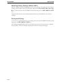
Recalling Factory Settings (RCALL-FACT)
Factory settings are those settings pre-selected at the factory. To recall (reset) the factory
settings, select the RCALL-FACT function and press the FF/LOAD/Micro Feed Up/
u key. After that select the SAVE&EXIT function and press the SEL/MENU/EXIT
key.
Options under the Set-Up and Adjustment functions are all initialized to the factory
settings.
Saving and Exiting
To exit the set-up mode and save your setting, first select the SAVE&EXIT function and
then press the SEL/MENU/EXIT key.
Any settings changed while in the Set-Up mode are saved as the new power-on defaults
for the printer. The new defaults remain active until you change them again.
4-18
Special mode
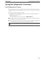
Using the Diagnostic Functions
Using the Diagnostic Functions
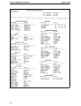
Print Configuration Function
This function prints a list of all the printer’s currently selected values. This function is useful for checking the printer settings when you first enter the Set-Up mode or just before
you exit.
To enter the Printer Configuration mode:
a) Make sure that the tractors are loaded with continuous feed paper and that the
paper select lever is set forward.
b) Turn the printer off.
c) Turn the printer back on while pressing the PARK/PRINT key.
The printer starts to print a list of the currently selected values. The pre-selected factory settings are shown on the opposite page.
To exit the Printer Configuration mode: After the printer has finished printing the list
of values, the printer will automatically restart in the power-up state.
Press the SEL/MENU/EXIT key to stop printing. Pressing the key again will resume printing. Press the FF/LOAD key in the pause state to execute a form feed.
4-19
Using the Diagnostic Functions
4-20
Special mode
Special mode
Using the Diagnostic Functions
Printing Test Function
The printing test function prints test pages independently of your computer to check
printing operations and quality. It does not check the interface between the computer and
the printer.
The printing test prints all of the characters available in the ASCII character set.
To enter the Printing Test mode:
a) Make sure that the tractors are loaded with continuous feed paper and that the
paper select lever is set forward.
b) Turn the printer off.
c) Turn the printer back on while pressing the PRINT QUALITY key.
Do not press any keys alone or in combination, except for pressing the PRINT QUALITY key
alone when turning the printer on, to avoid initiating unexpected tests not permitted for the user.
The printer starts to print rolling ASCII data as shown below.
To exit the Printer Configuration mode:
Printing Test mode is continues until power OFF.
_!"#$%&'()*+,-./0123456789:;<=>?@ABCDEFGHIJKLMNOPQRSTUVWXYZ[
!"#$%&'()*+,-./0123456789:;<=>?@ABCDEFGHIJKLMNOPQRSTUVWXYZ[\
"#$%&'()*+,-./0123456789:;<=>?@ABCDEFGHIJKLMNOPQRSTUVWXYZ[\]
#$%&'()*+,-./0123456789:;<=>?@ABCDEFGHIJKLMNOPQRSTUVWXYZ[\]^
$%&'()*+,-./0123456789:;<=>?@ABCDEFGHIJKLMNOPQRSTUVWXYZ[\]^_
%&'()*+,-./0123456789:;<=>?@ABCDEFGHIJKLMNOPQRSTUVWXYZ[\]^_`
&'()*+,-./0123456789:;<=>?@ABCDEFGHIJKLMNOPQRSTUVWXYZ[\]^_`a
'()*+,-./0123456789:;<=>?@ABCDEFGHIJKLMNOPQRSTUVWXYZ[\]^_`ab
()*+,-./0123456789:;<=>?@ABCDEFGHIJKLMNOPQRSTUVWXYZ[\]^_`abc
)*+,-./0123456789:;<=>?@ABCDEFGHIJKLMNOPQRSTUVWXYZ[\]^_`abcd
Press the SEL/MENU/EXIT key to stop printing. Pressing the key again will resume printing. Press the FF/LOAD key in the pause state to execute a form feed.
4-21
Using the Diagnostic Functions
Special mode
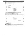
Hex Dump Mode
The Hex Dump mode prints data and commands in hexadecimal characters and abbreviated control codes. The ASCII characters are used for printing. No characters are printed
for hexadecimal codes 80 to FF. The Hex Dump mode is useful for checking whether
your computer is sending the correct commands to the printer and whether the printer is
executing the commands correctly. It is also useful for debugging software programs.
To enter the Printing Test mode:
a) Make sure that the tractors are loaded with continuous feed paper and that the
paper select lever is set forward.
b) Turn the printer off.
c) Turn the printer back on while simultaneously pressing the SHIFT key.
Do not press any keys alone or in combination, except for pressing the SHIFT key alone when
turning the printer on, to avoid initiating unexpected tests not permitted for the user.
Print the Hex Dump:
a) To start Hex Dump printing, send your file or program to the printer. The printer
goes online and prints the Hex Dump.
b) Press the SEL/MENU key to pause and resume printing in Hex Dump mode. To
resume Hex Dump printing, press the SEL/MENU key again.
c) To print another Hex Dump, send another file to the printer.
Exit the Hex Dump mode:
Turn the printer off to exit the Hex Dump mode.
Address
0000
0010
0020
0030
0040
0050
Hex data
00
10
20
30
40
50
01
11
21
31
41
51
02
12
22
32
42
52
03
13
23
33
43
53
04
14
24
34
44
54
05
15
25
35
45
55
.
.
.
.
.
.
.
.
.
.
.
.
ASCII
.
.
.
.
.
.
.
.
.
.
.
.
0C
1C
2C
3C
4C
5C
0D
1D
2D
3D
4D
5D
0E
1E
2E
3E
4E
5E
0F
1F
2F
3F
4F
5F
................
................
!"#$%&'()*+,-./
0123456789:;<=>?
@ABCDEFGHIJKLMNO
PQRSTUVWXYZ[\]^_
Press the SEL/MENU/EXIT key to stop printing. Pressing the key again will resume printing. Press the FF/LOAD key in the pause state to execute a form feed.
4-22
Special mode
Using the Diagnostic Functions
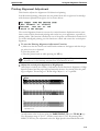
Printing Alignment Adjustment
This function adjusts the alignment of bi-directional printing.
In bi-directional printing, characters that are printed from left to right tend to misalign
with characters printed from right to left as shown below:
The vertical alignment function corrects the vertical character displacement that sometimes occurs with bi-directional printing and results in a poor appearance, especially in
printing tables. This function is defined as one of the power-on initiated test functions. If
you notice misaligned printing, use this function to check and correct the vertical print
alignment.
To enter the Printing Alignment Adjustment Function:
a) Make sure that the tractors are loaded with continuous feed paper and that the paper select lever is set forward.
b) Turn the printer off.
c) Turn the printer back on while pressing the LF key.
Do not press any keys alone or in combination, except for pressing the LF key alone when turning
the printer on, to avoid initiating unexpected tests not permitted for the user.
Adjust the vertical print alignment at High Speed:
After Paper is loaded, the format of adjustment for Bi-directional Alignment of High
Speed is printed and the paper will automatically advance for viewing after the printing is complete. The message of ”Bi-Dir Align Adjust1 = xx” is printed.
Align Adjust 1 = 08
An adjustment value is chosen using the PARK/PRINT/q or the TEAR/p key.
The adjustment range is "01-15", and the center value is "08". By pressing SEL/
MENU/EXIT key, the adjustment value for High Speed is determined and saved.
4-23
Using the Diagnostic Functions
Special mode
Adjust the vertical print alignment at Low Speed:
Adjustment of Bi-directional Alignment for Low Speed is performed immediately,
after the adjustment value for High Speed is saved. After Paper is loaded, the format
of adjustment for Bi-directional Alignment of Low Speed is printed and the paper will
au-tomatically advance for viewing after the printing is complete. The message of ”BiDir Align Adjust 2 = xx” is printed.
Low Speed
Align Adjust 2 = 08
An adjustment value is chosen using PARK/PRINT/q or the TEAR/p key. The
adjustment range is "01-15", and the center value is "08". By pressing SEL/MENU/
EXIT key, the adjustment value for Low Speed is determined and saved.
Printing new values:
The new adjustment values of Bi-directional Alignment is printed using 10cpi, Draft.
The paper is automatically advance for viewing after the printing is complete.
Align Adjust 1 = xx
Align Adjust 2 = xx
Exit from Printing Alignment Adjustment mode:
Turn off the printer.
4-24
Special mode
Using the Diagnostic Functions
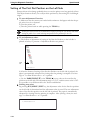
Top of Form Adjustment Function
Print positions often change gradually when you use the printer over long periods of time.
The ADJUST function allows you to adjust these positions by fine-tuning the Top of
Form origin.
To enter Top Adjustment Function:
a) Make sure that the tractors are loaded with continuous feed paper and that the paper select lever is set forward.
b) Turn the printer off.
c) Turn the printer back on while pressing the FF/LOAD key.
Do not press any keys alone or in combination, except for pressing the FF/LOAD key alone
when turning the printer on, to avoid initiating unexpected tests not permitted for the user.
To set Top Adjustment value:
a) The format of adjustment Loading Position is printed as below, 15 patterns of
adjustment Loading Position are printed.
10/60 inch
01 02 03 04 05 06 07 08 09 10 11 12 13 14 15
Loading Position = xx
b) The format of Loading Position is printed and the paper is automatically advanced
for viewing after the printing is complete. The message of ”Loading Position Pos =
xx” is printed.
c) Use the PARK/PRINT/q or the TEAR/p key to choose the new top position.
The adjustment range is "01-15", and the center value is "08". It is possible to set different values for Tractor and Manual.
Printing the new value:
By pressing SEL/MENU/EXIT key, the adjustment value for Loading Position is
determined and saved. The new adjustment values for Loading Position is printed.
The paper is automatically advanced for viewing after the printing is complete. After
ejecting a form, the message” Loading Position = xx” is printed.
Loading Position = xx
”xx” is new adjustment value.
Exit the Top Adjustment mode:
Turn the printer off to exit the Top Adjustment mode.
4-25
Using the Diagnostic Functions
Special mode
Setting of The First Dot Position on the Left Side
Print positions often change gradually when you use the printer over long periods of time.
This adjust function allows you to adjust these positions by fine-tuning the Left Margin
origin.
To enter Adjustment Function:
a) Make sure that the tractors are loaded with continuous feed paper and that the paper select lever is set forward.
b) Turn the printer off.
c) Turn the printer back on while pressing the TEAR key.
Do not press any keys alone or in combination, except for pressing the TEAR key alone when
turning the printer on, to avoid initiating unexpected tests not permitted for the user.
To set Adjustment value:
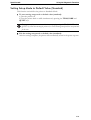
a) The format of adjustment of setting of the first dot Position on the left side is
printed as below, 15 patterns of adjustment Position are printed.
01H
02H
03H
04H
05H
06H
07H
08H
09H
10H
11H
12H
13H
14H
15H
10/60
inch
st
1 Print Position = xx
b) After the format of setting of the first dot Position on the left side is printed, the
paper is automatically advanced for viewing after the printing is complete. The message of ”1st Print Position Pos = xx” is printed.
c) Use the PARK/PRINT/q or the TEAR/p keys to choose the new first dot
position on the left side. The adjustment range is "01-15", and the center value is "08".
It is possible to set different values for Tractor and Manual.
Printing new value:
By pressing SEL/MENU/EXIT key, the adjustment value for the first dot position
on the left side is determined and the adjustment value is saved. The new adjustment
value of the first dot position on the left side is printed. The paper is automatically
advanced for viewing after the printing is complete. After ejecting a form, the message” 1st Print Position = xx” is printed.
st
1 Print Position = xx
4-26
Special mode
Using the Diagnostic Functions
”xx” is new adjustment value.
Exit the setting of the first dot position on the left side mode:
Turn the printer off to exit this mode.
4-27
Using the Diagnostic Functions
Special mode
Menu access
You can restrict the access to the Set-Up functions to avoid accidentally changing the SetUp options.
To enter Menu Access Function:
a) Make sure that the tractors are loaded with continuous feed paper and that the paper select lever is set forward.
b) Turn the printer off.
c) Turn the printer back on while pressing the SEL/MENU/EXIT and SHIFT
keys.
Do not press any keys alone or in combination, except for pressing the SEL/MENU/EXIT
and SHIFT key alone when turning the printer on, to avoid initiating unexpected tests not permitted for the user.
Changing Menu Access:
Press the FF/LOAD/Micro Feed Up/u key to print the current menu access value.
Use the PARK/PRINT/q or the TEAR/p keys to select the desired parameter.
Menu-Access Mode
Button
Menu-Access Action
PARK
TEAR
FF/LOAD
LF
SEL
Move cursor Down to the next Function or Value
Move cursor Up to the next Function or Value
Select the Option or Value and Move cursor Right
Select the Option or Value and Move cursor Left
Select the Option or value and Move to SAVE&EXIT
<FUNCTIONS>
MENU-ACCESS
ALL FUNCTION
NO ACCESS
Press the SEL/MENU key to select the desired menu access parameter and to activate the SAVE&EXIT position.
Press the SEL/MENU key again to save the new value and exit the Set-Up mode
and return to the Ready state. This setting remain in effect until the next time they are
changed.
4-28
Special mode
Using the Diagnostic Functions
Setting Setup Mode to Default Value (Standard)
This function can initialize the printer to Standard default.
To enter setting setup mode to default value (standard):
a) Turn the printer off.
b) Turn the printer back on while simultaneously pressing the TEAR, PARK and
QUIET keys.
Do not press any keys alone or in combination, except for pressing the TEAR, PARK and
QUIET key alone when turning the printer on, to avoid initiating unexpected tests not permitted
for the user.
Exit the setting setup mode to default value (standard):
After the setting completes, the printer will automatically restart in the power-up state.
4-29
5
Maintenance
Your printer requires very little care. Occasional cleaning and replacement of the ribbon
cartridge are all that is required (approximately every 6 months or 300 hours of operation,
whichever is sooner).
Lubrication of the printer is not usually necessary. If the printhead carriage does not move
smoothly back and forth, clean the printer in the manner described in this chapter. If the
problem continues, contact your dealer to determine whether lubrication may be necessary.
Cleaning
The housing and the top cover of the printer help protect it against dust, dirt, and other
contaminants. However, paper produces small particles that accumulate inside the printer.
This section explains how to clean and vacuum the printer and how to clean the paper bail
rollers.
It is easier to clean the printer when the cover is open.
Cleaning and Vacuuming the Printer
If the printhead carriage does not move smoothly back and forth or paper particles have
accumulated in the printer, clean the printer.
STOP
To avoid any possibility of injury, before cleaning the printer, turn off the
power to both the printer and the computer, and unplug the printer.
To clean and vacuum the printer:
Remove any paper from the printer. Make sure that the power is off, and then disconnect the printer power cord.
Using a soft vacuum brush, vacuum the exterior of the printer. Also vacuum the cut
sheet edge.
Use a soft, damp cloth to wipe the exterior of the printer, including the cover. A mild
detergent may be used.
Do not use solvents, kerosene, or abrasive cleaning materials that may damage the printer.
5-1
Cleaning
Maintenance
Open the cover of the printer and the protective cover of the platen and remove the
ribbon cartridge. Using a soft vacuum brush, gently vacuum the platen, the printhead
carriage and shaft, and surrounding areas. You can easily slide the printhead to the left
or right when the power is off. Be careful not to press too hard on the flat ribbon
cable that extends from the printhead carriage.
Protective
cover
Printhead cable
Re-install the ribbon cartridge (see “Installing the Ribbon Cartridge” on page 5-5).
Remove the single sheet feeder and clean the form tractors and the surrounding
areas.
Single sheet
feeder
Re-install the single sheet feeder.
5-2
Maintenance
Cleaning
Cleaning the Paper Rollers
Clean the platen and paper bail rollers occasionally or when stains or smudges appear on
the paper. Use a mild detergent as appropriate.
Do not use alcohol to clean the platen or the rollers. Alcohol may cause the
rubber to harden.
To clean the the rollers and the platen:
Apply a small amount of water to a soft cloth. Avoid spilling liquid inside the printer.
Place the cloth against the platen and manually rotate the platen knob.
Repeat this procedure for each roller.
To dry the platen, place a dry cloth against the platen and the rollers and manually
rotate the platen knob.
5-3
Replacing the Ribbon Cartridge
Maintenance
Replacing the Ribbon Cartridge
If printing is too light because of ribbon wear, replace the ribbon cartridge. Appendix E,
“Supplies and Options” lists the order number for the ribbon cartridge.
The replacement is almost the same as the installation except that it involves removing the
old ribbon cartridge and removing the new ribbon cartridge from the carton.
Removing the Ribbon Cartridge
To remove the ribbon cartridge:
Turn off the printer.
Open the top cover and the protective cover of the platen.
STOP
The printhead may be hot if you have been printing recently.
Move the print gap lever to position 6.
To remove the ribbon cartridge, press the ribbon release levers located on the sides of
the cartridge and carefully lift the cartridge out of the printer.
5-4
Maintenance
Replacing the Ribbon Cartridge
Installing the Ribbon Cartridge
Proceed as follows to install the ribbon cassette.
Only use ribbon cassettes from the manufacturer as products from other
manufacturers may damage the printhead or the ribbon drive.
Remove the ribbon cassette from its packaging.
Open the printer cover.
Adjust the printhead to the center of the print roller.
Turn the tension knob A in the direction of the arrow in order to take up slack of the
ribbon.
A
5-5
Replacing the Ribbon Cartridge
Maintenance
Insert the recess B on the bottom of the ribbon cassette into the holding pin C of the
mounting.
B
C
Push the cassette into its mounting until it clicks into position.
When placing the new ribbon cartridge on the carriage, make sure that the thin ribbon does not
become bunched or folded at the printhead. Readjust the print gap to achieve good print quality.
Close the cover of the printer.
Use the printing test function to check printing. See “Printing Test Function” on page 421 in chapter 4 “Special mode”.
5-6
Maintenance
Replacing the Print Head
Replacing the Print Head
If a specific dot is not printed for all characters, replace the printhead.
STOP
The printhead may be hot if you have been printing recently.
To remove the printhead:
Turn off the printer.
Open the cover and and the protective cover of the platen and remove the ribbon cartridge (see section “Removing the Ribbon Cartridge” on page 5-4).
Remove the two screws A from the printhead.
Lift the printhead and disconnect the flexible cable B.
B
A
A
Be careful because the printhead cables can easily be damaged.
We recommend that a technician perform this procedure.
To install the printhead:
Connect the flexible cables to each connector. Make sure to push them fully into the
connectors; do not kink the cables.
Be careful because the printhead cables can easily be damaged.
Ease the new printhead down into the mounting. Fasten the two screws A.
Install the ribbon cartridge (see section “Installing the Ribbon Cartridge” on page 5-5).
5-7
6
Troubleshooting
Your printer is extremely reliable, but occasional problems may occur. You can solve
many of these problems yourself, using this chapter. If you encounter problems that you
cannot resolve, contact your dealer or service partner for assistance.
This chapter is organized as follows:
• Solving problems
• Diagnostic functions
Solving problems
The tables in this section describe common printer problems and their solutions. The following types of problems are considered:
• Print quality problems
• Paper handling problems
• Operating problems
• Printer failure
6-1
Solving problems
Troubleshooting
Print Quality Problems and Solutions
Poor print quality or other printing problems are often caused by incorrect printer set-up
or incorrect software settings. A gradual decrease in print quality usually indicates a worn
ribbon. The following table identifies common print quality problems and suggests solutions.
6-2
Problem
Solution
Printing is too light or too dark.
Make sure that the ribbon cartridge is properly
installed and that the ribbon feeds smoothly.
Make sure that the Print Gap lever is set for the
thickness of your paper. Refer to Chapter 2, “Paper
handling”.
Check ribbon wear. Replace the ribbon if necessary.
Smears and stains appear on the
page.
Make sure that the Print Gap lever is set for the
thickness of your paper. Refer to the section “Paper
Thickness and Number of Copies” in Chapter 2, “Operating the printer”.
Check ribbon wear. Replace the ribbon if necessary.
Check whether the tip of the printhead is dirty.
Clean the head with a soft cloth if necessary.
The printhead should be changed by a technician.
Printing is erratic or the wrong
characters are printed. Many “?”
or unexpected characters are
printed.
Make sure that the interface cable is securely connected to both the printer and computer.
Make sure that the printer Emulation selected in
your software is the same as the Emulation
selected on the printer. For information on printer
emulations, refer to the section “PRINTER CONTROL menu” in Chapter 4, “Special mode”.
The page is blank.
Make sure that the ribbon cartridge is properly
installed. Refer to the section “Installing the Ribbon
Cartridge” in Chapter 5, “Maintenance”.
Printing is vertically misaligned
(jagged).
Use the printer's vertical alignment function to
check the vertical print alignment. If necessary,
adjust the print alignment. See the section “Printing
Alignment Adjustment” in Chapter 4, “Special mode”.
Printing is too light, probably
you hear sporadically "ticktack".
As the ribbon may be blocked or stuck, please try
replacing the ribbon.
Troubleshooting
Solving problems
Problem
Solution
The top margin is wrong.
The top margin is the sum of the printer’s top-ofform setting, the software-specified top margin,
and the printer’s TOP-MARGIN setting. Proceed
as follows:
• Make sure that the top-of-form setting is correct.
The factory default is 0 mm (0 inch).
• Check the software-specified top margin. Refer
to your software documentation.
• Check the printer’s TOP-MARGIN setting. See
the section “COMMON (PUSH TRAC) menu” or
“FRICTION menu” in Chapter 4, “Special mode”.
Lines are double spaced instead
of single spaced.
Change the CR CODE setting in the printer SetUp mode to CR=LF+CR. See “SET-UP menu” in
Chapter 4, “Special mode”.
The printer overprints on the
same line.
Change the CR CODE setting in the printer SetUp mode to CR=LF+CR. See “SET-UP menu” in
Chapter 4, “Special mode”.
The next print line starts where
the previous line ended instead
of at the left margin.
Change the CR CODE setting in the printer SetUp mode to LF=LF+CR. See “SET-UP menu” in
Chapter 4, “Special mode”.
The printer overprints on the
same line while the next print
line starts where the previous
line ended instead of at the left
margin.
Change the CR CODE setting in the printer SetUp mode to CR=LF+CR and LF=LF+CR. See
“SET-UP menu” in Chapter 4, “Special mode”.
6-3
Solving problems
Troubleshooting
Paper Handling Problems and Solutions
The following table describes common paper handling problems and suggests solutions.
See the section “Paper handling” in Chapter 2, “Operating the printer” for detailed procedures
on loading and using paper.
6-4
Problem
Solution
Paper cannot be loaded or fed.
Make sure that the Print Gap select lever located
on the top right of the printer is set correctly.
Move the lever to the rear for single sheets or to
the front for continuous forms.
Make sure that the paper covers the paper-out sensor, (i.e., the left paper edge is within 60 mm from
the left edge).
Paper jams while loading.
Turn off the printer and remove the jammed
paper.
Remove any obstructions from the paper path.
Make sure that the Print Gap lever is set for the
thickness of your paper. See “Paper Thickness and
Number of Copies” in Chapter 2, “Operating the
printer”.
Make sure that the paper is not folded, creased, or
torn.
Make sure that the left and right tractors are set so
that the continuous forms are stretched taut. See
“Fanfold paper” in Chapter 2, “Operating the printer”.
Paper jams while printing.
Turn off the printer and remove the jammed
paper.
Remove any obstructions from the paper path.
Make sure that the Print Gap lever is set for the
thickness of your paper. See “Paper Thickness and
Number of Copies” in Chapter 2, “Operating the
printer”.
For continuous forms, make sure that the incoming and outgoing paper stacks are correctly placed.
Paper should feed straight. See “Feeding and Positioning Paper” in Chapter 2, “Operating the printer”.
Paper slips off the forms tractors
or the perforated holes of the
paper tear during printing.
Make sure that the forms tractors are positioned
correctly for the width of your paper and that the
perforated holes of the paper fit directly over the
tractor pins. See “Fanfold paper” in Chapter 2,
“Operating the printer”.
Troubleshooting
Solving problems
Operating Problems and Solutions
The following table identifies common operating problems and suggests solutions. If you
cannot resolve a problem, contact your dealer.
Problem
Solution
The power does not turn on.
} Make sure that the power cord is securely con-
nected to both the printer and the battery. Make
sure that the power outlet is functional. If not so,
use other outlet.
} Turn the power off. Wait a minute and then turn
the printer on again. If the printer still has no
power, contact your dealer.
The printer is on but it will not
print.
} Make sure that the Ready indicator is lit. See “Op-
erations of the Control Panel” in Chapter 2, “Operating the printer”.
} If you use the interface cable make sure it is se-
curely connected to both the printer and the
computer.
} If the ALARM indicator is lit, load paper. See
“Loading paper” in Chapter 2, “Operating the printer”.
} Run the printer printing test. If the printing test
executes normally, the problem is caused by the
interface, the computer, incorrect printer settings, or incorrect software settings. See “Printing
Test Function” in Chapter 4, “Special mode”.
} Make sure that the printer Emulation selected in
your software is the same as the Emulation selected on the printer. See “PRINTER CONTROL menu” in Chapter 4, “Special mode”.
Paper select lever error
If paper is loaded and the paper select lever is
moved backward or forward, the printer turns
offline, the ALARM LED lights and the CHARACTER PITCH LED 10 blinks.
} Switch the paper select lever back to its original
position.
6-5
Solving problems
Troubleshooting
LED states in error conditions
LEDs light up depending on the following error types.
6-6
LEDs
Status
Description
Recovery
ALARM
Other LEDs
on
Normal status
No paper loaded.
Load paper.
ALARM
Other LEDs
on
Normal status
Paper near end.
Make sure that
enough paper is
loaded.
ALARM
PRINT QUALITY
CHARACTER PITCH 10
12
15
17
20
Prop
on
all off
off
off
blinking
off
off
off
A paper jam has
occured.
Remove the
jammed paper.
ALARM
PRINT QUALITY
CHARACTER PITCH 10
12
15
17
20
Prop
on
all off
blinking
off
off
off
off
off
Paper is loaded
into the printer
and the paper
select lever was
moved backward
or forward.
Switch the paper
select lever back
to its original
position.
ALARM
PRINT QUALITY
CHARACTER PITCH 10
12
15
17
20
Prop
on
all off
off
off
off
off
blinking
off
An interface error
has ocurred while
transferring data.
Press the SEL key
twice.
Troubleshooting
Solving problems
Printer Failures
A user cannot generally resolve a problem involving defective printer hardware. On detecting a fatal error, the printer will:
• Stop printing
• Turn the Ready (SEL/MENU) indicator off
• Blink the ALARM indicator
Power off and on again the printer, to recover a fatal error. If you cannot resolve the problem, contact your dealer or service partner.
6-7
Diagnostic Functions
Troubleshooting
Diagnostic Functions
The printer diagnostic functions are printing test, hex-dump mode and printing alignment
adjustment.
• PRINTING TEST tells you whether the printer hardware is functioning correctly. If
the printer hardware is functional, any problems you are having are probably caused by
incorrect printer settings, incorrect software settings, the interface, or the computer.
• HEX-DUMP MODE allows you to determine whether the computer is sending the
correct commands to the printer, and whether the printer is executing the commands
correctly. This function is useful to programmers or others who understand how to interpret hex dumps.
• PRINTING ALIGNMENT ADJUSTMENT allows you to check and, if necessary,
correct theprinter’s vertical print alignment in bi-directional mode.
For details on using these functions, all of which are available in the printer special mode,
see the section “Using the Diagnostic Functions” in Chapter 4, “Special mode”.
6-8
A
Specifications
This appendix provides the physical, functional, and performance specifications for your
printer. It also contains detailed paper specifications.
Printer specifications
Item
Printing method
24-wire dot matrix impact printer
Character pitch
10, 12, 15, 16.6, 17, 20 characters/inch and proportional type
(emulation-dependent)
Print width
80 characters/line at 10 cpi
96 characters/line at 12 cpi
137 characters/line at 17 cpi
Print speed
Carriage Speed
Draft
LQ
39.9 / 13.3 ips
39.9 / 13.3 ips
26.7 / 13.3 ips
20 / 13.4 ips
20 / 13.3 ips
399 cps
479 cps
400 cps
343 cps
400 cps
133 cps
160 cps
200 cps
229 cps
267 cps
at 10 cpi
at 12 cpi
at 15 cpi
at 17.1 cpi
at 20 cpi
Line spacing
1, 2, 3, 4, 5, 6, 8, 12 lines/inch
Resolution
360 vertical × 360 horizontal dots per square inch
Character density
10 cpi
Draft
Letter
vertical x horizontal
24 x 12
24 x 36
Fonts
Draft, Roman, Sans Serif, Courier, OCR-A, OCR-B, Prestige,
Script, Orator, Gothic, Souvenir
Barcodes
UPC/A, UPC/E, EAN8, EAN13, Code 39, Code 128, Codabar,
Interleaved 2 of 5, Industrial 2 of 5, Postnet
A-1
Printer specifications
Specifications
Item
Narrow model
Wide model
Character sets
ISO USA, ISO UK, ISO France, ISO Germany, ISO Italy, ISO Sweden, ISO Norway, ISO Spain, ISO Portugal, Epson USA , Epson
France, Epson Germany, Epson UK, Epson Denmark, Epson Sweden, Epson Italy, Epson Spain, Epson Japan, Epson Norway, Epson
Denmark II, Epson Spain II, Epson Latin America, Epson Korea,
Epson Legal, CRO-ASCII, Arabic Farsi, Arabic Urdo, Greek DEC,
Greek ELOT 928, CP437 Latin US, CP737Greek, CP850 Latin1,
CP851 Greek, CP852 Latin2, CP857 Turkish, CP858 IBM with Euro,
CP860 Portugal, CP861 Icelandic, CP863 French Canada, CP864
Arabic, CP864 Arab. Extended, CP865 Nordic, CP866 Cyrillic,
CP866 Bulgaria, Siemens Turkish, DEC Turkish, CP1250 Win Latin2,
CP1251 Win Cyrillic, CP1252 Win Latin1, CP1253 Win Greek,
CP1254 Win Turkish, 8859-1 Latin1, 8859-1, Latin1(SAP), 8859-2
Latin2, 8859-5 Cyrillic, 8859-7 Greek, 8859-9 Turkish, 8859-15
Latin9(Euro)BRASCII, Abicomp, Roman 8, Coax/Twinax(Hebrew),
New-437(Hebrew)
NOTE: Code pages and Fonts support depend on supplied Font by
the manufacturer. The Character Sets are emulation dependent
A-2
Interface
Parallel IEEE-1284 bidirectional Centronics,
USB 2.0 Full Speed (12 Mbps)
Interface option
Ethernet, Serial RS-232C
Emulations
EPSON ESC/P2, IBM Proprinter X(L)24e
OKI superset commands for both and emulations available
Power supply
U.S.A./Canada 120 V ± 10%, 60 Hz ± 2%, Europe 230 V ± 10%,
50/60 Hz ± 2%
Power consumption
at 100% throughput 40 VA (with Rolling ASCII) when idling 6.5 VA
Sound pressure
level LpAm
£55 dB(A) in LQ (ISO 7779)
Dimensions
398 (W) x 330 (D) x135 (H) mm
Weight
6.7 kg
Approvals
UL 1950 (with deviation 3) Listed, CSA C22.2 NO.950 (with deviation
3) Certified, FCC Class B (J subpart of 15) Certified, CE marking,
EMC Immunity: IEC61000-4-2 level3, Energy Star
Specifications
Printer specifications
Paper specifications
Only use paper that corresponds to the paper specifications and test new sorts of paper
before use.
Paper type
Continuous Forms
Width
Length
No. of copies
Form thickness (max.)
102–267 mm (4–10.5 in)
102 mm (4 in) up to 559 mm (22 in)
1 to 5
0.35 mm (0.014 in)
Single Sheets
Width
Length
Thickness
102–267 mm (4–10.5 in)
76–364 mm (3–14.3 in)
0.35 mm (0.014 in)
A-3
Paper specifications
Specifications
Print Area
This section illustrates the recommended print area for single sheets and continuous
forms.
Continuous forms
Narrow model: Wc 102 to 267 mm (4 to 10.5 in)
Lc 5.08 to 25.4 mm (0.2 to 1 in)
A-4
Specifications
Paper specifications
Single sheets
Narrow model: Ws 102 to 267 mm (4 to 10.5 in)
Hs 76 to 364 mm (3 to 14.3 in)
Ls 5.08 to 32 mm (0.2 to 1.26 in)
A-5
Paper specifications
A-6
Specifications
Specifications
Paper specifications
Paper Thickness
Paper thickness is given by the weight of the paper in either grams per square meter
(g/m2) or in pounds per bond (lbs/bond). The following table shows the allowable paper
thickness for one-part paper or for each sheet of multipart paper. The total thickness must
not exceed 0.35 mm (0.014 inch).
The weight of carbonless or carbon-backed paper may vary, depending on the paper manufacturer. When using paper of borderline thickness, test the paper before running a job.
Type of Paper
Number of Parts
Thickness
One-Part Carbonless
Single
47–81 g/m2 (12–22 lbs/bond)
Two-Part Carbonless
Top
40–64 g/m2 (11–17 lbs/bond)
Bottom
40–81 g/m2 (11–22 lbs/bond)
Top
40–64 g/m2 (11–17 lbs/bond)
Middle
40–64 g/m2 (11–17 lbs/bond)
Bottom
40–81 g/m2 (11–22 lbs/bond)
Top
40–64 g/m2 (11–17 lbs/bond)
Middle
40–64 g/m2 (11–17 lbs/bond)
Middle
40–64 g/m2 (11–17 lbs/bond)
Bottom
40–81 g/m2 (11–22 lbs/bond)
Top
40–64 g/m2 (11–17 lbs/bond)
Middle
40–64 g/m2 (11–17 lbs/bond)
Middle
40–64 g/m2 (11–17 lbs/bond)
Middle
40–64 g/m2 (11–17 lbs/bond)
Bottom
40–81 g/m2 (11–22 lbs/bond)
Top
40–64 g/m2 (11–17 lbs/bond)
Bottom
40–81 g/m2 (11–22 lbs/bond)
Top
40–64 g/m2 (11–17 lbs/bond)
Middle
40–64 g/m2 (11–17 lbs/bond)
Bottom
40–81 g/m2 (11–22 lbs/bond)
Top
40–64 g/m2 (11–17 lbs/bond)
Middle
40–64 g/m2 (11–17 lbs/bond)
Middle
40–64 g/m2 (11–17 lbs/bond)
Bottom
40–81 g/m2 (11–22 lbs/bond)
Three-Part Carbonless
Four-Part Carbonless
Five-Part Carbonless
Two-Part Carbon-Backed
Three-Part Carbon-Backed
Four-Part Carbon-Backed
A-7
Paper specifications
Five-Part Carbon-Backed
Two-Part Carbon-Interleaved
Three-Part Carbon-Backed
Specifications
Top
40–64 g/m2 (11–17 lbs/bond)
Middle
40–64 g/m2 (11–17 lbs/bond)
Middle
40–64 g/m2 (11–17 lbs/bond)
Middle
40–64 g/m2 (11–17 lbs/bond)
Bottom
40–81 g/m2 (11–22 lbs/bond)
Top
40–64 g/m2 (11–17 lbs/bond)
Carbon
Counted as one sheet
Bottom
40–81 g/m2 (11–22 lbs/bond)
Top
40–64 g/m2 (11–17 lbs/bond)
Carbon
Counted as one sheet
Middle
40–64 g/m2 (11–17 lbs/bond)
Carbon
Counted as one sheet
Bottom
40–81 g/m2 (11–22 lbs/bond)
Carbon-backed: Do not use in high humidity environments.
Carbon-interleaved: Avoid using single sheets format in carbon-interleaved.
A-8
B
Interfaces
Your printer offers by default the possibility of operating either via a parallel interface or
an USB interface. In addition, a serial interface (RS232C) or an Ethernet interface are
available as options. Interfaces may vary from unit to unit depending on which configuration is purchased.
This appendix provides information you may need for wiring your own interface cables
or for programming computer-to-printer communications. Most users do not need the information in this appendix. To simply connect your printer to your computer, follow the
instructions in Chapter 2, “Operating the printer”, section “Connecting the interface cable”.
Parallel interface
This parallel interface can operate in the following two modes:
• Unidirectional (forward channel) mode or compatible mode: This printer supports a conventional Centronics interface.
• Bidirectional (forward/reverse channel) mode or nibble mode: This printer supports a bidirectional communication per Nibble mode of the IEEE 1284 Standard.
The cable connector at the printer side should be a shielded, Amphenol DDK57FE30360 or equivalent.
The connector pin assignments are given in the following tables by modes. In the tables:
• “Input” denotes a signal from the computer to the printer.
• “Output” denotes a signal from the printer to the computer.
• The standard signal levels are 0.0 to +0.4 V (low), and +2.4 to +5.0 V (high).
B-1
Parallel interface
Interfaces
Parallel Interface Pin Assignment
B-2
Pin No.
Signal
In/Out
Pin No.
Parallel
1
nSTROBE
In
19
Signal GND
2
DATA0
In
20
Signal GND
3
DATA1
In
21
Signal GND
4
DATA2
In
22
Signal GND
5
DATA3
In
23
Signal GND
6
DATA4
In
24
Signal GND
7
DATA5
In
25
Signal GND
8
DATA6
In
26
Signal GND
9
DATA7
In
27
Signal GND
10
nACK
Out
28
Signal GND
11
BUSY
Out
29
Signal GND
12
PE
Out
30
Signal GND
13
SELECT
Out
31
nINIT
In
14
nAUTOFEED
Out
32
nERROR
Out
15
NC
33
Signal GND
16
Signal GND
34
NC
17
Chassis GND
35
+5V DC
Out
18
+5V DC
36
nSELECT IN
In
Out
In/Out
Interfaces
Parallel interface
Compatible mode
Pin No.
Signal name
Direction
Description
1
nSTROBE
Input
This signal is a strobe pulse for reading
data (Data 0 to 7). The printer reads data
when this signal is low. The pulse width
must be 1 µs or more at the receiving terminal.
2–9
Data 0 to 7
Input
Data 8 (pin 9) is the most significant bit;
however, this pin is not used in 7-bit
ASCII communications. Logical 1 signals
must go high at least 1 µs before the falling edge of the Data Strobe signal and
must stay high for at least 1 µs after the
rising edge.
10
nACK
Output
This pulse signal indicates that the printer
has received data and is ready to accept
the next set of data. This signal is also
sent when the printer is switched from
offline to online.
11
BUSY
Output
Data cannot be received when this signal
is high. This signal is high during data
entry, when the printer is offline, when
the buffer is full, or when an error occurs.
12
Paper Empty
(PE)
Output
This signal is high when the printer is out
of paper.
13
Select (SLCT)
Output
This signal is high when the printer is
online.
14
nAUTOFEED
Input
Not used
31
nINIT
Input
If this signal is low for more than 50 µs,
the printer is reset to the initial condition
and is placed online. If the received data
remains in the buffer, the printer continues to print until the buffer becomes
empty.
32
nERROR
36
nSELECT IN
This signal is low when the printer is
offline, paper is out, or when there is a
printer error.
Input
Not used
B-3
Parallel interface
Interfaces
Nibble mode
Pin No.
B-4
Signal name
Direction
Description
10
PtrClk
(nACK)
Output
Reverse data transfer phase: This signal
goes high when data being sent to the
host is established.
Reverse idle phase: This signal is set low
then goes high to interrupt the host, indicating that data is available.
11
PtrBusy
(BUSY)
Output
Reverse data transfer phase: Data bit 3,
data bit 7, then forward path (host to
printer) busy status.
12
AckDataReq
(PE)
Output
Reverse data transfer phase: Data bit 2,
then data bit 6.
Reverse idle phase: This signal is set high
until the host requests data and, after that,
follows the Data Available signal.
13
Xflag
(SELECT)
Output
Reverse data transfer phase: Data bit 1
then 5.
14
HostBusy
(nAUTOFEED)
Input
Reverse data transfer phase: This signal is
set low when the host can receive data,
and goes high when the host has received
data. Following a reverse data transfer,
the interface enters the reverse idle phase
when the HostBusy signal goes low and
the printer has no data.
Reverse idle phase: This signal goes high
when the Printer Clock signal goes low so
that the interface re-enters the reverse
data transfer phase. If it goes high with
the 1284 Active signal low, the 1284 idle
phase is aborted and the interface returns
to the compatibility mode.
32
nDataAvail
(nERROR)
Output
Reverse data transfer phase: This signal is
set low when the printer is ready to send
data to the host. During the data transfer,
it is used as data bit 0 (LSB), then data
bit 4.
Reverse idle phase: This signal is used to
indicate that data is available.
Interfaces
Parallel interface
Data Transmission Timing
In unidirectional mode (conventional Centronics interface), this printer guarantees the received data when the Data and Data Strobe signals from the computer have the following
timing with respect to the Busy and Acknowledge signals from the printer.
DATA
0.5 min.
0.5 min.
nSTB
0.5 min.
0 min.
approx. 5
nACK
0 min.
0.5 max.
BUSY
T2
1 max.
T1
nINIT
50 min.
Notes:
1) All timing are in microseconds.
2) The minimum value for T1 (printer initializing time) is TBD millisecond.
3) The minimum value for T2 (printer processing time) is TBD microsecond.
4) Printer initialization occurs at the falling edge of nINIT.
In bidirectional mode (nibblemode), this printer can send data to the computer. Data is
sent in units of four bits (nibble) using four output signal lines as data paths. The following outlines one byte of data sent during reverse data transfer phase in nibble mode.
B-5
USB interface
Interfaces
USB interface
The USB (Universal Serial Bus) interface has the following features:
• Full compliance with the Universal Serial Bus Specification Revision 2.0 for Full Speed
Mode.
• USB Function Controller with two FIFO-based Endpoints:
– One bidirectional Control Endpoint 0 (8 bytes)
– One receive Endpoint 1 (1*64 bytes)
• The signaling bit rate is 12 MB/s (Full speed).
Descriptor
Standard Device Descriptor
Offset
B-6
Field
Size
Value
Description
0
bLength
Byte
0x12
Size of this descriptor in bytes.
1
bDescriptorType
Byte
0x01
Device descriptor type.
2
bcdUSB
Word
0x0210
USB Spec. release No. in BCD.
4
bDeviceClass
Byte
0x00
Class code
5
bDeviceSubClass
Byte
0x00
Sub Class code
6
bDeviceProtocol
Byte
0x00
Protocol code
7
bMaxPacketSize0
Byte
0x08
Maximum packet size for EP0
8
idVendor
Word
0x0C22
Vendor ID for Customer
10
idProduct
Word
0x08A6
Product ID for Project
SDM500
12
bcdDevice
Word
0x0100
ROM Version in BCD
14
iManufacture
Byte
0x01
Index of string descriptor
describing Manufacture.
15
iProduct
Byte
0x02
Index of string descriptor
describing Product.
16
iSerialNumber
Byte
0x03,
Index of string descriptor
describing the device’s serial
number.
17
bNumConfiguration
Byte
0x01
Number of possible configurations.
Interfaces
USB interface
Configuration Descriptor
Offset
Field
Size
Value
Description
0
bLength
Byte
0x09
Size of this descriptor in bytes.
1
bDescriptorType
Byte
0x02
Configuration descriptor type.
2
wTotalLength
Word
0x0019
No. of bytes in this configuration. This includes the configuration descriptor plus all of
interface and endpoint descriptors.
4
bNumInterfaces
Byte
0x01
Project SDM500 has 1 interface.
5
bConfigurationValue
Byte
0x01
Value to use as an argument to
SetConfiguration() request to
select this configuration.
6
iConfiguration
Byte
0x00
Index of string descriptor
describing this configuration.
7
bmAttributes
Byte
0xC0
Configuration characteristics:
D7 : Reserved (set to 1) D6 :
Self-powered D5 : Remote
wakeup D4 . . . D0 : Reserved
(set to 0) (Self Powered /
RemoteWakeup UnSupport)
8
MaxPower
Byte
0x31
Maximum power consumption
of this configuration. (98mA)
Interface Descriptor Alternate Setting
Offset
Field
Size
Value
Description
0
bLength
Byte
0x09
Size of this descriptor in bytes.
1
bDescriptorType
Byte
0x04
Interface descriptor type.
2
bInterfaceNumber
Byte
0x00
Number of Interface.
3
bAlternateSetting
Byte
0x00
Value used to select alternate
setting for the interface identified in the prior field.
4
bNumEndPoints
Byte
0x02
Number of endpoints used by
this interface (excluding Endpoint 0).
5
bInterfaceClass
Byte
0x07
Class code (Printer class).
B-7
USB interface
Interfaces
Offset
Field
Size
Value
Description
6
bInterfaceSubClass
Byte
0x01
Subclass code (Printer subclass).
7
bInterfacePotocol
Byte
0x01
Receive.
8
iInterface
Byte
0x00
Index of string descriptor
describing this interface.
Field
Size
Value
Description
0
bLength
Byte
0x07
Size of this descriptor in bytes.
1
bDescriptorType
Byte
0x05
Interface descriptor type.
2
bEndPointAddress
Byte
0x01
This is an Out endpoint, Endpoint 1.
3
bmAttributes
Byte
0x02
This is a Bulk endpoint.
4
wMaxPacketSize
Word
0x0040
Maximum data transfer size.
6
bInterval
Byte
0x00
(This field is ignored for bulk.)
Field
Size
Value
Description
0
bLength
Byte
0x07
Size of this descriptor in bytes.
1
bDescriptorType
Byte
0x05
Interface descriptor type.
2
bEndPointAddress
Byte
0x82
This is an In endpoint, Endpoint 2.
3
bmAttributes
Byte
0x02
This is a Bulk endpoint.
4
wMaxPacketSize
Word
0x0040
Maximum data transfer size.
6
bInterval
Byte
0x00
(This field is ignored for bulk.)
Endpoint 1 Descriptor
Offset
Endpoint 2 Descriptor
Offset
B-8
Interfaces
Serial interface (option)
Serial interface (option)
Your printer’s optional serial interface supports the RS232C specification. The signals are
received and transmitted by a 25 pin female connector.
Use a serial interface cable that meets the requirements of your host PC.
Serial attachment characteristics
Signal Description for RS232C
Pin No.
Signal Name
Description
2
TXD
(Transmit Data)
This line is for transmission of data from Printer to
PC. The characteristics of the data transmitted are
specified by the function menu. The only data that
will be transmitted are XON (x’11’) and XOFF
(x’13’) signals. CTS must be high for transmission
to take place.
3
RXD
(Receive Data)
This line is for receiving data from PC. The serial
interface will not accept any data unless DSR is on.
4
RTS
(Request to Send)
If user selects DTR as Busy line, this line will be set
high and will remain high after the serial interface
finishes its Reset.
If user selects RTS as Busy line, this line will be set
high after the serial interface finishes its Reset
sequence. However if Ready/busy handshake protocol is selected, this line is used to indicate to PC
whether or not Printer is ready to receive any more
data.
5
CTS
(Clear to Send)
This line will be monitored only if the XON/XOFF
protocol is selected because CTS must be high in
order for the serial interface to transmit data.
6
DSR
(Data Set Ready)
DSR is used as another method of providing data
integrity. Data will not be accepted unless DSR is
high.
By setting of setup menu, choice of valid / invalid is
possible.
8
DCD
(Data Carrier Detect)
Asserted by DCE when a connection has been
established with remote equipment.
11
SSD
(Supervisory Send Data)
If user selects SSD as Busy line, this line will be set
high or low and will remain high or low after the
serial interface finishes its Reset.
If user selects SSD as Busy line, this line will be set
high or low after the serial interface finishes its
Reset sequence. However if Ready/busy handshake protocol is selected, this line is used to indicate to PC whether or not Printer is ready to
receive any more data.
B-9
Serial interface (option)
20
Interfaces
DTR
(Data Terminal Ready)
If user selects RTS as Busy line, this line will be set
high and will remain high after the serial interface
finishes its Reset.
If user selects DTR as Busy line, this line will be set
high after the serial interface finishes its Reset
sequence. However if Ready/busy handshake protocol is selected, this line is used to indicate to PC
whether or not Printer is ready to receive any more
data.
Serial Interface Timings
Ready/Busy
INIT
RTS
BUSY
(DTR)
DSR
Receive Data
Valid
1
2
Receive Data
1. Data received when DSR is low is considered invalid and will be discarded.
2. BUSY LOW (DTR) is dropped to indicate to the host that the receive buffer is full.
B-10
Interfaces
Serial interface (option)
XON/XOFF:
INIT
RTS
DSR
1
Receive Data
Valid
CTS
2
XON
XOFF
XON
XMT Data
3
4
Receive Data
Data received when DSR is low is considered invalid and will be discarded.
CTS is required in order for the XON/XOFF protocol to work, because CTS is
required in order for data transmission to occur. After Reset, when CTS is detected,
an XON will be sent.
However, PC is not required to detect this initial XON before transmitting data to
Printer.
Printer transmits an XOFF to indicate to PC that the receive buffer is full.
An XON will be transmitted to PC when buffer space is again available, and the
printer is ready to receive more data.
And if data is sent from Host more after outputting XOFF, XOFF will be output
every 16bytes receiving.
B-11
Serial interface (option)
Interfaces
Serial Interface Error Handling
The serial interface recognizes the following errors:
• Parity Error
• Framing Error
• Buffer Overrun
Parity Errors:
When a parity error is detected, printer will indicate warning status on the lights Printer
continues to receive data.
Framing Errors:
When a framing error is detected, printer will indicate warning status on the lights. Printer
continues to receive data.
Buffer Overrun Errors:
Buffer overrun errors occur when PC does not obey the selected protocol and continuous
to send data when Printer cannot accept any more data. The buffer on Printer overflows
if PC sends more than 1024 bytes of data after the interface signals that it is “Busy”. The
result is lost data, since there is no way to make PC stop sending data. When a parity error
is detected, printer will indicate warning status on the lights.
B-12
Interfaces
Serial interface (option)
Data rates
The interface supports the following data rates.
• 4800 bps
• 9600 bps
• 19200 bps
• 38400 bps
Supported protocols
This interface will also support the following:
• 7 or 8 Data Bits
• Even, Odd, None Parity
• 1 or 2 Stop Bit(s)
• Ready/Busy or XON/XOFF handshaking
Data Transfer
A data frame consists of a start bit, seven or eight data bits, 0 or 1 parity bit(s) and 1 or
2 stop bit(s). With these combinations, 9, 10, 11 and 12 bit frames are available:
START
7 or 8 Data Bits
0 or 1
PARITY bit
1 or 2
STOP bit(s)
Parity
There are three possible parity settings: Even, Odd, None.
} When Even parity is specified, the interface expects to receive data frames with even
parity and will transmit data with even parity.
} When Odd parity is specified, the interface expects to receive data frames with odd
parity and will transmit data with odd parity.
} Parity will be checked whenever Even of Odd parity is selected. When a parity error
is detected, printer will indicate warning status on the lights. Printer will continue to
receive data.
} When None parity is specified, the interface does not accept data frames to include a
parity bit, and the interface transmits data without parity bits.
B-13
Serial interface (option)
Interfaces
Handshake
Handshaking in the serial environment is most commonly handled by software and/or
hardware. The manipulation of the hardware handshaking is handled by the following 4
lines:
} RTS (Request to Send)
} CTS (Clear to Send)
} DSR (Data Set Ready)
} DTR (Data Terminal Ready)
Ready/Busy (Hardware Handshake)
When Ready/Busy protocol is selected, DTR will be used to pace the data flow from PC.
When the serial interface is BUSY (Buffer is full, Printer is out of paper or an error is detected), DTR will be dropped to indicate to PC that Printer cannot receive any more data.
XON/XOFF (Software Handshake)
When XON/XOFF protocol is selected, Printer indicates to PC that it is busy and not
ready to receive any more data by sending an XOFF (DC3 X’13’) character. When the serial interface is ready to receive more data, an XON (DC1 X’11’) will be transmitted.
B-14
Interfaces
Serial interface (option)
Configuring the serial interface of the PC
DOS mode/Command line
To use the serial interface of your PC, you must add the following mode commands to
the AUTOEXEC.BAT file:
mode com1:9600,n,8,1,p
mode lpt1:= com1:
With the first MODE command, you configure the serial interface Com1 of your PC to
the printer’s factory defaults. The second MODE command redirects the parallel standard
output port LPT1 of your PC to Com1.
Bits per second:
Parity:
Data bits:
Stop bits:
9600 bauds
none
8
1
These settings must be modified to use different values.
Windows 95/98
Click on the Start button in the Windows taskbar. Move the mouse to Settings and click
on Control Panel. Click on System, followed by Device Manager. Click on Ports,
COM1 and Port Settings.
Bits per second:
Data bits:
Parity:
Stop bits:
9600 bauds
8
none
1
These settings must be modified to use different values.
Windows 2000/XP
Click on the Start button in the Windows taskbar. Click on Printers (Windows 2000) or
on Printers and Faxes (Windows XP) to open the printer folder. In the menu bar, click
on File and Server Properties. Click on Ports, then select COM1 and click on Configure.
Bits per second:
Data bits:
Parity:
Stop bits:
9600 bauds
8
none
1
These settings must be modified to use different values.
B-15
Auto Select Interface
Interfaces
Auto Select Interface
The printer can receive data transmitted either a parallel interface or a USB interface as
standard. In addition, the printer can receive data transmitted either serial interface or Ethernet interface as option.
When two different data is sent from different PCs, one by a parallel interface and the other by a USB interface in standard, or one by a parallel interface and the other by a optional
serial interface, the data reached the printer is received first and processed first and the
Busy signal is sent to other interfaces (Second).
Parallel interface and Ready/Busy in Serial interface. In case of XON/XOFF in Serial interface, Printer sends XOFF to Host, if Host send data to Printer:
Other (Second) I/F
Status (during prior I/F to be activated)
Parallel (Compatible mode)
BUSY to High
USB
NAK (first 1 packet data to be received)
RS-232C (Ready/Busy)
BUSY
RS-232C (XON/XOFF)
XOFF
The printer has received all data and the receive buffer is cleared, the Busy status is cleared
and the printer starts to receive the data from the other interface when the state where
data are not received continues 1 seconds or more.
B-16
C
Command Sets
This appendix describes printer commands and their parameters.
This printer has the following resident command sets (Emulations):
} EPSON ESC/P2, IBM Proprinter X(L)24e
Select the same Emulation on the printer and in your software.
C-1
24 wire printer
Command Sets
Printer basic functions
General
I/F
USB 2.0 Full Speed
IEEE1284 Nibble Mode
Emulation
IBM Pro printer XL24E
EPSON ESC/P2 (T.B.D None Scalable font)
Character Set
ISO USA, ISO UK, ISO France, ISO Germany, ISO Italy, ISO
Sweden, ISO Norway, ISO Spain, ISO Portugal, Epson USA ,
Epson France, Epson Germany, Epson UK, Epson Denmark,
Epson Sweden, Epson Italy, Epson Spain, Epson Japan, Epson
Norway, Epson Denmark II, Epson Spain II, Epson Latin
America, Epson Korea, Epson Legal, CRO-ASCII, Arabic
Farsi, Arabic Urdo, Greek DEC, Greek ELOT 928, CP437
Latin US, CP737Greek, CP850 Latin1, CP851 Greek, CP852
Latin2, CP857 Turkish, CP858 IBM with Euro, CP860 Portugal, CP861 Icelandic, CP863 French Canada, CP864 Arabic,
CP864 Arab. Extended, CP865 Nordic, CP866 Cyrillic, CP866
Bulgaria, Siemens Turkish, DEC Turkish, CP1250 Win Latin2,
CP1251 Win Cyrillic, CP1252 Win Latin1, CP1253 Win Greek,
CP1254 Win Turkish, 8859-1 Latin1, 8859-1, Latin1(SAP),
8859-2 Latin2, 8859-5 Cyrillic, 8859-7 Greek, 8859-9 Turkish,
8859-15 Latin9(Euro) BRASCII, Abicomp, Roman 8, Coax/
Twinax(Hebrew), New-437(Hebrew)
Typeface
HS Draft, Draft, Roman, Sans Serif, Courier, OCR-B, OCR-A,
Prestige, Script, Orator, Gothic, Souvenir
Printhead
24 wire
Print resolution
(10cpi)
180 x 80 dpi (HS Draft)
180 x 120 dpi (Draft)
180 x 360 dpi (LQ)
Character Pitch
10, 12, 15, 17.1, 20 and 24cpi
Enchanted print
Double width , Double height ,Double strike and Italic etc.
Printing speed
480 cps (HS Draft 10cpi), 400cps (Draft 10cpi), 133cps (LQ
10cpi)
Indicator
LED
Bar code Fonts
UPC/A, UPC/E, EAN8, EAN13,
Code 39, Code 128, Codabar, Interleaved 2 of 5
Industrial 2 of 5, Postnet
Options
Interface
C-2
Ethernet
RS-232C(4800, 9600, 19200, 38400 bps)
Command Sets
24 wire printer
Emulation
Command list
IBM mode
The printer supports the commands shown below.
Command sequence
Function
Horizontal position control
BS
08H
Backspace
HT
09H
Horizontal tab
CR
0DH
Carriage return
ESC BS
1BH 08H
Backspace
ESC HT
1BH 09H
Horizontal tab
ESC CR
1BH 0DH
Carriage return
ESC D
1BH 44H
Set horizontal tabs
ESC X
1BH 58H
Set horizontal margins
ESC d
1BH 64H
Relative mode inline forward
Vertical position control
LF
0AH
Line feed
VT
0BH
Vertical tab
FF
0CH
Form feed
ESC LF
1BH 0AH
Line feed
ESC VT
1BH 0BH
Vertical tab
ESC FF
1BH 0CH
Form feed
ESC 0
1BH 30H
Select 1/8” line spacing
ESC 1
1BH 31H
Select 7/72” line spacing
ESC 2
1BH 32H
Start text line spacing
ESC 3
1BH 33H
Set graphics line spacing
ESC 4
1BH 34H
Set top of form
ESC 5
1BH 35H
Automatic line feed
ESC A
1BH 41H
Set text line spacing
ESC B
1BH 42H
Set vertical tabs
ESC C
1BH 43H
Set form length in lines
ESC C 0
1BH 43H 00H
Set form length in inches
ESC J
1BH 4AH
Graphics variable line spacing
ESC N
1BH 4EH
Set automatic perforation skip
C-3
24 wire printer
Command Sets
ESC O
1BH 4FH
Cancel automatic perforation skip
ESC [ \
1BH 5BH 5CH
Set vertical units
ESC ]
1BH 5DH
Reverse line feed
Character attributes
SO
0EH
Double-wide printing by line
SI
0FH
Condensed printing
DC2
12H
Select 10 cpi
DC4
14H
Cancel double-wide printing by line
ESC SO
1BH 0EH
Double-wide printing by line
ESC SI
1BH 0FH
Condensed printing
ESC DC2
1BH 12H
Select 10 cpi
ESC DC4
1BH 14H
Cancel double-wide printing by line
ESC -
1BH 2DH
Continuous underscore
ESC :
1BH 3AH
Select 12 cpi
ESC E
1BH 45H
Select emphasized mode
ESC F
1BH 46H
Cancel emphasized mode
ESC G
1BH 47H
Select double strike mode
ESC H
1BH 48H
Cancel double strike mode
ESC I
1BH 49H
Select print mode
ESC P
1BH 50H
Proportional space mode
ESC S
1BH 53H
Start subscript or superscript printing
ESC T
1BH 54H
Cancel subscript or superscript printing
ESC W
1BH 57H
Continuous double-wide printing
ESC [-
1BH 5BH 2DH
Score select
ESC [ @
1BH 5BH 40H
Set presentation highlight
ESC [I
1BH 5BH 49H
Set font global
ESC [d
1BH 5BH 64H
Set print quality
ESC _
1BH 5FH
Continuous over score
Download and character code setting
C-4
ESC 6
1BH 36H
Select character set 2
ESC 7
1BH 37H
Select character set 1
ESC =
1BH 3DH
Character font image download
ESC [ T
1BH 5BH 54H
Set code page
ESC \
1BH 5CH
Print continuously from all character chart
Command Sets
24 wire printer
Command sequence
Function
Bitimage
ESC K
1BH 4BH
Normal density bit image graphics
ESC L
1BH 4CH
Dual density bit image graphics
ESC Y
1BH 59H
Dual density bit image graphics
ESC Z
1BH 5AH
High density bit image graphics
ESC [ g
1BH 5BH 67H
High resolution graphics
ESC [ f
1BH 5BH 66H
Setup barcode parameter
ESC [ p
1BH 5BH 70H
Set barcode data
BEL
07H
Beeper
DC1
11H
Select printer
DC3
13H
Deselect printer
CAN
18H
Cancel Data
ESC BEL
1BH 07H
Beeper
ESC DC1
1BH 11H
Select printer
ESC DC3
1BH 13H
Deselect printer
ESC CAN
1BH 18H
Cancel data
ESC EM
1BH 19H
Set Auto Sheet Feeder Mode
ESC Q
1BH 51H
Deselect printer
ESC R
1BH 52H
Set all tabs to power on settings
ESC U
1BH 55H
Set print direction
ESC [ K
1BH 5BH 4BH
Set initial condition
ESC j
1BH 6AH
Stop printing
ESC r
1BH 72H
Color selection
ESC *
1BH 2AH
Select Graphics Mode
ESC 3
1BH 33H
Set graphics line spacing (n/180”)
ESC A
1BH 41H
Set text line spacing (n/60”)
ESC J
1BH 4AH
Graphics variable line spacing (n/180”)
Barcode
Others
AGM control command
C-5
24 wire printer
Command Sets
EPSON mode
The printer supports the commands shown below.
Command sequence
Function
Horizontal position control
BS
08H
Backspace
HT
09H
Horizontal Tab
CR
0DH
Carriage Return
ESC $
1BH 24H
Set Absolute Print Position
ESC D
1BH 44H
Select Horizontal Tabs
ESC Q
1BH 51H
Set Right Margin
ESC \
1BH 5CH
Set Relative Print Position
ESC a
1BH 61H
Select Justification
ESC l
1BH 6CH
Set Left Margin
Vertical position control
C-6
LF
0AH
Line Feed
VT
0BH
Vertical Tab
FF
0CH
Form Feed
ESC (C
1BH 28H 43H
Set Page Length in Define Unit
ESC (U
1BH 28H 55H
Set Unit
ESC (V
1BH 28H 56H
Set Absolute Vertical Print Position
ESC (c
1BH 28H 63H
Set Page Format
ESC (v
1BH 28H 76H
Set Relative Vertical Print Position
ESC +
1BH 2BH
Select n/360” Line Spacing
ESC /
1BH 2FH
Select Vertical Tab Channel
ESC 0
1BH 30H
Select 1/8” Line Spacing
ESC 2
1BH 32H
Select 1/6” Line Spacing
ESC 3
1BH 33H
Set Graphics Line Spacing (n/180”)
ESC A
1BH 41H
Set n/60” Line Spacing
ESC B
1BH 42H
Set Vertical Tabs
ESC C
1BH 43H
Set Page Length in Lines
ESC C 0
1BH 43H 00H
Set Page Length in Inches
ESC J
1BH 4AH
Perform n/180-inch Line Feed
ESC N
1BH 4EH
Set Skip Over Perforation
ESC O
1BH 4FH
Cancel Skip Over Perforation
ESC b
1BH 62H
Select Vertical Tabs in Channels
ESC j
1BH 6AH
Perform Reverse n/180-inch Line Feed
Command Sets
24 wire printer
Command sequence
Function
Character attributes
SO
0EH
Double-Wide Printing 1 Line
SI
0FH
Select Condensed Mode
DC2
12H
Cancel Condensed Mode
DC4
14H
Cancel Double-Wide Printing 1 Line
ESC SO
1BH 0EH
Double-Wide Printing 1 Line
ESC SI
1BH 0FH
Select Condensed Mode
ESC !
1BH 21H
Master Select
ESC ( -
1BH 28H 2DH
Select Score
ESC -
1BH 2DH
Auto Underscore
ESC 4
1BH 34H
Select Italic Mode
ESC 5
1BH 35H
Cancel Italic Mode
ESC E
1BH 45H
Select Emphasized Mode
ESC F
1BH 46H
Cancel Emphasized Mode
ESC G
1BH 47H
Select Double-strike Mode
ESC H
1BH 48H
Cancel Double-strike Mode
ESC M
1BH 4DH
Select 12 cpi
ESC P
1BH 50H
Select 10 cpi
ESC S
1BH 53H
Select Subscript or Superscript Printing
ESC T
1BH 54H
Cancel Subscript or Superscript Printing
ESC W
1BH 57H
Turn Double-wide Mode On/Off
ESC X
1BH 58H
Select Font by Pitch and Point
ESC c
1BH 63H
Set Horizontal Motion Index (HMI)
ESC g
1BH 67H
Select 15 cpi
ESC k
1BH 6BH
Select Typestyle Family
ESC p
1BH 70H
Turn Proportional Mode On/Off
ESC q
1BH 71H
Select Character Style
ESC w
1BH 77H
Turn Double-high Mode On/Off
ESC x
1BH 78H
Select Letter Quality or Draft
Download and character code setting
ESC %
1BH 25H
Select User-defined Set
ESC &
1BH 26H
Define User-Defined Characters
ESC (^
1BH 28H 5EH
Print Data as Characters
ESC 6
1BH 36H
Enable Printable Characters
C-7
Command sequence
Function
Download and character code setting
ESC 7
1BH 37H
Enable Upper Control Codes
ESC :
1BH 3AH
Copy ROM to RAM
ESC R
1BH 52H
Select an International Character Set
ESC t
1BH 74H
Select Character Table
ESC ( t
1BH 28H 74H
Assign Character Table
ESC (G
1BH 28H 47H
Select Graphics Mode
ESC *
1BH 2AH
Select Bit Image
ESC .
1BH 2EH
Print Raster Graphics
ESC ?
1BH 3FH
Reassign Graphics Mode
ESC K
1BH 4BH
Select Single-density Graphics Mode
ESC L
1BH 4CH
Select Double-density Graphics Mode
ESC Y
1BH 59H
Select High-speed Double-density Graphics Mode
ESC Z
1BH 5AH
Select Quadruple-Density Graphics Mode
1BH 28H 42H
Barcode Setup and Print
BEL
07H
Beeper
DC1
11H
Select Printer
DC3
13H
Deselect Printer
CAN
18H
Cancel Line
DEL
7FH
Delete Character
ESC EM
1BH 19H
Set Auto Sheet Feeder Mode
ESC SP
1BH 20H
Set Inter Character Space
ESC #
1BH 23H
Cancel MSB Control
ESC <
1BH 3CH
Select Unidirectional Mode 1 Line
ESC =
1BH 3DH
Set MSB to 0
ESC >
1BH 3EH
Set MSB to 1
ESC @
1BH 40H
Initialize Printer
ESC U
1BH 55H
Turn Unidirectional Mode On/Off
ESC r
1BH 72H
Color selection
Graphics
Barcode
ESC ( B
Others
C-8
Command Sets
24 wire printer
Printer unique commands
Epson emulation
ESC DLE @ Pn A1 A2 P1 P2 P3
P4
27 16 64 Pn A1 A2 P1 P2 P3 P4
Set multiple print positions
ESC DLE A m n1 ... n8
27 16 65 m n1 ... n8
Select bar code type and size
ESC DLE B m n [data]
27 16 66 m n [data]
Print bar code data
ESC DLE C P1 [data]
27 16 67 P1 [data]
Print Postnet bar code data
ESC DLE G n 1
27 16 71 n 49
Set/reset raster graphics
ESC US 0
27 31 48
End double height printing
ESC US 1
27 31 49
Begin double height printing
ESC [ n
27 91 n
Set line spacing to n/360"
ESC ] n
27 93 n
Perform n/360" line feed
ESC i 0
27 105 48
Incremental printing off
ESC i 1
27 105 49
Incremental printing on
ESC n Pn
27 110 Pn
Select Graphics Aspect Ratio
ESC s 0
27 115 48
Half-speed printing off
ESC s 1
27 115 49
Half-speed printing on
ESC } NUL
27 125 0
Software I-Prime
ESC X p Pn Lp Hp
27 88 70 Pn Lp Hp
Select character pitch/point size 32 Points
C-9
24 wire printer
Command Sets
IBM emulation
C-10
ESC DLE @ Pn A1 A2 P1 P2 P3
P4
27 16 64 Pn A1 A2 P1 P2 P3 P4
Set multiple print positions
ESC DLE A m n1 ... n8
27 16 65 m n1 ... n8
Select bar code type and size
ESC DLE B m n [data]
27 16 66 m n [data]
Print bar code data
ESC DLE C P1 [data]
27 16 67 P1 [data]
Print Postnet bar code data
ESC DLE F Pno Pn Lp Hp
27 16 70 Pno Pn Lp Hp
Select character
ESC % 4 n
27 37 52 n
Perform n/360" line feed
ESC % 5 n
27 37 53 n
Perform n/144" line feed
ESC % 8 n
27 37 56 n
Set line spacing to n/360
ESC % G
27 37 71
Italic printing on
ESC % H
27 37 72
Italic printing off
ESC 8
27 56
Paper-out sensor off
ESC 9
27 57
Paper-out sensor on
ESC [ I Ln Hn Hfid Lfid Hfwd
Lfwd fa
27 91 108
Select font
ESC e n1 n2
27 101 n1 n2
Set left relative position
ESC g
27 103
Select 15 cpi
ESC i 0
27 105 48
Incremental printing off
ESC i 1
27 105 49
Incremental printing on
ESC n Pn
27 110 Pn
Select Graphics Aspect
Ratio: PPR only
ESC q n
27 113 n
Specify outline/shadow
pitch/point size upto 64 Points (scalable fonts)
Command Sets
24 wire printer
ESC x 0
27 120 48
Select Utility print mode
ESC x 1
27 120 49
Select LQ print mode
ESC { n
27 123 n
Change emulation
ESC } NUL
27 125 0
Software I-Prime
C-11
Barcodes
Barcodes
IBM mode
Available barcode types
} CODABAR (NW7)
} EAN-13
} EAN-8
} CODE 39
} INDUSTRIAL 2 OF 5
} INTERLEAVED 2 OF 5
} UPC-A
} UPC-E
} POST-NET
} CODE128
Epson mode
Available barcode types
} EAN-13
} EAN-8
} INDUSTRIAL 2 OF 5
} UPC-A
} UPC-E
} CODE 39
} CODE128
} POSTNET
} CODABAR (NW7)
} INTERLEAVED 2 OF 5
C-12
Command Sets
D
Character Sets
This appendix provides character sets available for this printer. Available character sets
depend on the emulation selected. They are as follows:
• IBM Proprinter X(L)24E emulation: Set 1 and set 2, codepages
• Epson-ESC/P(2) emulation: National character sets
These character sets include different characters and symbols that are in accordance with
the intended languages or usages. Note that some character sets, even if they have the
same character set name, may not have certain characters or symbols, depending on the
resident fonts selected.
D-1
IBM Proprinter Emulation
IBM Proprinter Emulation
IBM Set 1 and 2
IBM Set 1
IBM Set 2
D-2
Character Sets
Character Sets
Epson ESC Emulation
Epson ESC Emulation
National Character Sets
The following fifteen character sets are available: USA, France, Germany, UK, Denmark
1, Sweden, Italy, Spain 1, Japan, Norway, Denmark 2, Spain 2, Latin America, Korea, and
Legal.
Common Characters
The following table shows characters common to the fifteen “national” character sets. NR
indicates characters that differ with languages.
D-3
Epson ESC Emulation
Character Sets
National Characters
The following table shows “national” characters that differ with languages. Character codes correspond to NRs in the preceding table.
D-4
Character Sets
Restriction of fonts
Non scalable fonts
D-5
Restriction of fonts
D-6
Character Sets
Character Sets
Restriction of fonts
Scalable Fonts and Code Pages
SIDM scalable font T.B.D
The printer does not support all code pages in the all fonts.
See the Code page table and notes.
Note1) The Roman typeface is selected on these code pages.
Note2) The OCR-A and OCR-B typeface are available on ASCII character set and a part of
character of code page 437, 850, 860, 863, 865 and 858. OCR-A and OCR-B font are not
able to be printed by Euro Symbol character.
Note3) The followings code pages support scalable font.
Other code pages cancel multipoint mode and the printer set a point to 10.5 point.
Font name
PC 437
PC 850
PC 858
PC 860
PC 863
PC 865
HS Draft
-
-
-
-
-
-
Draft
-
-
-
-
-
-
Roman
o
o
o
o
o
o
Sans Serif
o
o
o
o
o
o
Courier
Note 1
Note 1
Note 1
Note 1
Note 1
Note 1
OCR-B
Note 1
Note 1
Note 1
Note 1
Note 1
Note 1
OCR-A
Note 1
Note 1
Note 1
Note 1
Note 1
Note 1
Prestige
Note 1
Note 1
Note 1
Note 1
Note 1
Note 1
Script
Note 1
Note 1
Note 1
Note 1
Note 1
Note 1
Orator
Note 1
Note 1
Note 1
Note 1
Note 1
Note 1
Gothic
Note 1
Note 1
Note 1
Note 1
Note 1
Note 1
Souvenir
Note 1
Note 1
Note 1
Note 1
Note 1
Note 1
Font name
PC 852
PC 851
PC 866
Cyrillic
8859-9
Turkish
8859-15
Latin9
HS Draft
-
-
-
-
-
Draft
-
-
-
-
-
Roman
o
o
o
o
o
Sans Serif
o
o
o
o
o
Courier
Note 1
Note 1
Note 1
Note 1
Note 1
OCR-B
Note 1
Note 1
Note 1
Note 1
Note 1
OCR-A
Note 1
Note 1
Note 1
Note 1
Note 1
Prestige
Note 1
Note 1
Note 1
Note 1
Note 1
D-7
Restriction of fonts
D-8
Character Sets
Script
Note 1
Note 1
Note 1
Note 1
Note 1
Orator
Note 1
Note 1
Note 1
Note 1
Note 1
Gothic
Note 1
Note 1
Note 1
Note 1
Note 1
Souvenir
Note 1
Note 1
Note 1
Note 1
Note 1
E
Supplies and Options
This appendix lists the accessories and options available for the printer. Contact your dealer for information on ordering any of these items.
The installation of options allows you to expand the capabilities of your printer.
Supplies
Supply
Order Number
Black Ribbon Cartridge
99081
Ribbon Fabric
99002
E-1
Interface Modules
Supplies and Options
Interface Modules
Interface
E-2
Order Number
Serial interface module, RS-232C, Sub D 25 pin-f connector
043444
Ethernet interface module 10/100 Mb/s
043445
“All rights reserved. Translations, reprinting or copying by any means of this manual complete or in part
or in any different form requires our explicit approval. We reserve the right to make changes to this manual without notice. All care has been taken to ensure accuracy of information contained in this manual.
However, we cannot accept responsibility for any errors or damages resulting from errors or inaccuracies
of information herein.”
DASCOM REPRESENTATIVES
GERMANY
UNITED KINGDOM
DASCOM Europe GmbH
Heuweg 3
D-89079 Ulm
Deutschland
Tel.: +49 (0) 731 2075 0
Fax: +49 (0) 731 2075 100
www.dascom.com
DASCOM GB Ltd
Hart House, Priestley Road,
Basingstoke, Hampshire
RG24 9PU, England
Phone: +44 (0) 1256 481481
Fax: +44 (0) 1256 481400
www.dascom.com
SINGAPORE (ASIA PACIFIC)
DASCOM AP Pte Ltd
21 Bukit Batok Crescent
#29-81, WCEGA Tower
Singapore 658065
Phone: +65 6760 8833
Fax: +65 6760 1066
www.dascom.com
AMERICAS
DASCOM Americas Corporation
427 W. Main Street
Waynesboro, VA 22980
USA
Phone: +1 (877) 434 13 77
www.dascom.com
© 2013 DASCOM
FRANCE
DASCOM Europe GmbH
117 Avenue Victor Hugo
92100 Boulogne-Billancourt
France
Phone: +33 73 02 51 98
www.dascom.com