1
APPLICATION NOTE
Using the SUTRON RADAR LEVEL CONTROLLER (RLR-0002-1) with a MULTI-MODEM GPRS
(Wireless Modem MTCBA-G-F4)
Using the
SUTRON RADAR LEVEL CONTROLLER
(RLR-0002-1)
with a
MULTIMODEM GPRS
(Wireless Modem MTCBA-G-F4)
November 2008
Prepared by:
Integrated Systems Division
November 2008
1
APPLICATION NOTE
2
Using the SUTRON RADAR LEVEL CONTROLLER (RLR-0002-1) with a MULTI-MODEM GPRS
(Wireless Modem MTCBA-G-F4)
TABLE OF CONTENTS
PRODUCT OVERVIEW............................................................................................................................................3
SUTRON RADAR LEVEL RECORDER (RLR-0002-1).........................................................................................3
MULTIMODEM GPRS............................................................................................................................................3
SETUP AND OPERATION........................................................................................................................................4
STARTING THE RADAR LEVEL SENSOR .......................................................................................................................4
STARTING MULTIMODEM ..........................................................................................................................................4
Insert SIM card ....................................................................................................................................................5
Powering and connecting the modem ..................................................................................................................5
Configuring the GSM Modem ..............................................................................................................................6
COMMAND LINE INTERFACE ......................................................................................................................................6
GSM Modem AT commands-Command Line. ......................................................................................................6
LED status............................................................................................................................................................7
Disabling Modbus mode in the radar via front panel ..........................................................................................7
Changing the baud rate in the radar via front panel ...........................................................................................7
MODBUS INTERFACE...........................................................................................................................................8
GSM Modem AT commands- MODBUS ..............................................................................................................8
Configuring the Radar – MODBUS .....................................................................................................................9
Configuring AutoPoll.........................................................................................................................................10
CONNECTING GSM MODEM TO THE RADAR................................................................................................13
TESTING MODEM WITH RADAR LEVEL SENSOR ........................................................................................13
COMMAND-LINE INTERFACE .......................................................................................................................13
MODBUS INTERFACE .....................................................................................................................................14
APPENDIX A : COMMAND LINE INTERFACE:...............................................................................................15
LIST OF COMMANDS .................................................................................................................................................15
APPENDIX B : CABLING .......................................................................................................................................17
RLR-0002-1 (DB9 CONNECTOR) ............................................................................................................................17
MTCBA-G-F4 (RS-232 15-PIN CONNECTOR PINOUT)...........................................................................................19
APPLICATION NOTE
3
Using the SUTRON RADAR LEVEL CONTROLLER (RLR-0002-1) with a MULTI-MODEM GPRS
(Wireless Modem MTCBA-G-F4)
1. PRODUCT OVERVIEW
1.1
SUTRON RADAR LEVEL RECORDER (RLR-0002-1)
The RLR-0002-1 has a front panel that allows a user to setup the operating parameters, monitor performance and
perform tests. The RLR-0002-1 is both a sensor and a logger, allowing for stand-alone and integrated applications.
The log inside the RLR-0002-1 is capable of holding more than 300 000 readings, and allows the recording of status
and stage (stage) data. The RLR-0002-1 has an SDI-12 interface as well as RS232 so it can provide data to data
loggers or communications equipment.
The RS232 port supports a simple command line mode compatible with HyperTerminal and
other communications programs to display data from the log and perform some essential
operating functions. It is possible to connect the radar to a modem or radio.
Features
•
•
•
•
•
•
•
•
•
•
•
•
Non-contact measurement of stage (water level).
Low power consumption (<1ma quiescent, <20ma measuring @ 12V) for long battery
life.
High precision featuring 0.001 ft resolution a range of 60ft.
High accuracy 0.01ft 5- 20ft, 0.05% reading 20-60ft.
Powerful and configurable processing filters out waves (Averaging and DQAP)
Automatically saves data in permanent log
User-settable measurement, logging, and averaging
Built-in flash log for 300,000 readings safeguards your data even if power is lost
Stand-alone operation or operation with other loggers/communications via SDI-12 and
RS232
Automatically computes discharge
Front panel allows full access to setup, status and data
Provides redundant data storage when connected to a logger
1.2 MULTIMODEM GPRS
The Multi-Tech MultiModem® GPRS is an external data/fax/voice wireless modem. It also
supports mobile originated short message service (SMS) and mobile-terminated SMS. It offers
standard-based multi-band GPRS Class 10 performance. This ready-to-deploy, standalone
modem allows developers to add wireless communication to products with a minimum of
development time and expense.
Features
• GPRS Class 10 operation
• Quad-band 850/900/1800/1900
• GSM Class 1 and Class 2 Group 3 FAX
• Desktop or panel mounting
APPLICATION NOTE
4
Using the SUTRON RADAR LEVEL CONTROLLER (RLR-0002-1) with a MULTI-MODEM GPRS
(Wireless Modem MTCBA-G-F4)
•
•
•
•
•
•
•
•
•
•
•
•
•
•
•
•
Short Message Services including text and PDU, point-to-point, cell broadcast
14.4K GSM circuit switched data
SMA antenna connector and SIM socket
Serial interface supports DTE speeds to 115.2K
AT command compatible
MNP2 V.42bis data compression
Numerous LEDs provide operational status
ME + SIM phone book management
Fixed dialing number
SIM Toolkit Class 2
SIM, network and service provider locks
Real time clock
Alarm management
UCS2 character set management
Packet data up to 85K bps
Embedded TCP/IP stack
NOTE: The purpose of this application note is to focus on the configuration and connection of
the modem using the RS232 interface.
To obtain information about General Specifications of the previous mentioned equipments
access the following web sites.
http://www.sutron.com/products/RadarLevelRecorder.htm
http://www.multitech.com/DOCUMENTS/Collateral/data_sheets/86002084.pdf
2. SETUP AND OPERATION
2.1 Starting the radar level sensor
The radar level sensor starts operating as soon as power is applied. A green blinking LED tells
the user that the radar level sensor is operational. The only way to stop the radar is removing
power from it.
Setting up the radar level sensor via the front panel is one option for setting Time, Baud Rate,
Stage, Enable or Disable Modbus etc. (for more information see RLR-0002-1 User’s manual).
2.2 Starting Multimodem
First of all, before we configure the modem, the user will need to activate the modem from a
local service provider with a DATA SERVICE PLAN (Circuit Switch Data). A SIM card will be
provided to the user by the service provider for each device.
IMPORTANT! The modem should have Circuit Switched Data (CSD) enabled from the
wireless carrier.
APPLICATION NOTE
Using the SUTRON RADAR LEVEL CONTROLLER (RLR-0002-1) with a MULTI-MODEM GPRS
(Wireless Modem MTCBA-G-F4)
Once the Modem has been activated, it needs to be powered up, hooked up to the antenna,
configured and tested.
Requirements:
• MTCBA-G –F4 Modem
• SIM card
• RS-232 cable (15 to 9 pin)
• Power supply
• Antenna
• PC running Windows
The GSM modem comes with six LEDs indicators in the front panel. These LEDs indicate the
operating status of the GSM modem which makes them very helpful when we are testing the
GSM modem.
LED Indicators
TD
Transmit Data. Lit when modem is transmitting data.
RD
Receive Data. Lit when modem is receiving data.
CD
Carrier Detect. Lit when data connection has been established.
LS
TR
Line Status.
Continuous “on” state indicates that the wireless modem is not registered on the network.
Flashing state indicates registration on network. Off state. Modem is off (not ready) or in download
mode.
Terminal Ready. Commonly called “Data Terminal Ready.” This is a readiness signal from the PC.
PWR
Power. Indicates presence of DC power when lit.
2.2.1 Insert SIM card
Insert the SIM card into the SIM card slot.
2.2.2
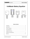
2.2.3 Powering and connecting the modem
Power: Plug the power supply into the modem (via
2.5mm miniature power jack).
Antenna: Connect a suitable antenna to the SMA
connector.
Serial Cable: Connect both sides of the serial and
control cable (15-pin Sub D connector on the modem
side)
5
APPLICATION NOTE
6
Using the SUTRON RADAR LEVEL CONTROLLER (RLR-0002-1) with a MULTI-MODEM GPRS
(Wireless Modem MTCBA-G-F4)
2.2.4 Configuring the GSM Modem
In order to configure the GSM modem, you must use a terminal application such as
HyperTerminal in Windows. To open this program, go to: Start>All
programs>Accessories>Communications>Hyper Terminal.
AT commands can be used to operate, configure and query the GSM modem. A reference guide
is included on the Multi-Tech Web site. AT commands used in this application notes will be
necessary to configure the GSM modem for our purpose.
After we power up and connect the modem to the COM port in your PC, we should be able to
communicate to the modem via Hyper Terminal. The parameters of communication for the Port
Settings Tap in the Hyper Terminal configuration are:
• Bits per second: 9600
•
Data Bits: 8
•
Parity: None
•
Stop Bits: 1
•
Handshaking: Hardware.
At this point we should be able to communicate with the GSM modem. To verify it, we can type
the command “AT&V” (then ENTER), this command will show the current settings of the GSM
modem.
The GSM Modem programming depends on the type of interface selected in the setting of the
radar level sensor (RLR-0002-1). Two modem interfaces are available to the radar level sensor:
Command-line and MODBUS.
In the following sections we will explain the necessary configuration for the GSM modem and
the radar level sensor in each interface: Command-line and MODBUS.
2.3 Command Line Interface
This section describes how to configure both the GSM modem and Radar Level Sensor for
Command-Line interface. The MODBUS mode must be disabled in the radar level sensor to
communicate via Command-line interface. This configuration will allow you to use Hyper
Terminal to remote access the data in the radar.
2.3.1 GSM Modem AT commands-Command Line.
The following AT commands are required to program the GSM modem. First, you have to
connect the GSM modem to a PC and configure the modem using Hyper Terminal in Windows.
You must use a RS 232 serial cable to connect the GSM modem to a PC. This configuration
will allow you to access the command line interface in the radar via Hyper Terminal. Type a
<Enter> after each command.
7
APPLICATION NOTE
Using the SUTRON RADAR LEVEL CONTROLLER (RLR-0002-1) with a MULTI-MODEM GPRS
(Wireless Modem MTCBA-G-F4)
AT+VGR=1
AT+VGT=255
AT+CBST=7,0,1
1=Non transparent only)
AT+IPR=9600
commands)
AT+ICF=3,4
AT+IFC=2,2
AT+FCLASS=0
AT+CSNS=4
ATS0=2
AT&D2
release)
AT&C1
ATQ0
AT&W
(Use to tune the receive gain of the speakers)
(Use to tune the transmit gain of the microphone)
(7 = 9600bps, 0 = only asynchronous modem,
(Data rate at which the modem will accept
(Character framing modem serial port 3= 8 Data 1 stop, 4=
None)
(Hardware flow control mode 2= RTS, 2= CTS)
(0 = Data operating mode)
(Select de bearer 4=data)
(Numbers of rings before automatic answer)
(Upon DTR switch from ON to OFF, the call id
(Controls Data Carrier Detect Signal (DCD) )
(0 = Modem transmit result codes)
(Save configuration)
After all programming is done; you can use “AT&V” command to verify the modem
configuration. This should show:
AT&V
Q:0 V:1 S0:002 S2:043 S3:013 S4:010 S5:008
+CR:0 +CRC:0 +CMEE:0 +CBST:7,0,1
+SPEAKER:0 +ECHO:0,1 &C:1 &D:2 %C:0
+IPR:9600 +ICF:3,4 +IFC:2,2
2.3.2 LED status.
The LEDs on the GSM modem front
the status of the modem. The LEDs
follow:
PWR
Continuous ON
TR
Continuous ON
LS
Flashing
panel tell you
should be as
2.3.3 Disabling Modbus mode in the radar via front panel
Press the down arrow to Station Setup then press the right arrow. Press the down arrow to
Modbus Settings then press the right arrow. Clicking the Set button select Disable.
2.3.4 Changing the baud rate in the radar via front panel
APPLICATION NOTE
8
Using the SUTRON RADAR LEVEL CONTROLLER (RLR-0002-1) with a MULTI-MODEM GPRS
(Wireless Modem MTCBA-G-F4)
From the factory, the default baud rate setting in the radar level sensor is 115200. The modem
baud rate is set to 9600. To change the radar level sensor baud rate, press the down arrow to
Station Setup then press the right arrow. Press the down arrow to Other Settings then press the
right arrow. Press the down arrow to Baud Rate then select 9600.
Now you are ready to connect the GSM modem to the Radar Level Recorder.
2.4 MODBUS INTERFACE
This section illustrates how to configure the GSM modem and Radar Level Sensor for MODBUS
interface and explain how to configure AutoPoll program to support MODBUS.
MODBUS is a standard communication protocol supported by several Sutron loggers (See
www.MODBUS.org).
AutoPoll is a program for the PC used to perform scheduled remote data collection from Sutron
data loggers. AutoPoll supports multiple protocols, including MODBUS. AutoPoll download
data .LOG files from the Radar Level Recorder. This downloaded data is saved in your PC as
.CSV file.
(See : http://www.sutron.com/beta/AutoPoll/AutoPoll.htm for more information)
2.4.1 GSM Modem AT commands- MODBUS
The following AT commands are required to program the GSM modem so the modem
can communicate properly with the PC via MODBUS interface.
First, you have to connect the GSM modem to a PC and configure the modem using
Hyper Terminal in Windows. You must use a RS 232 serial cable to connect the GSM
modem to a PC.
Type a <Enter> after each command.
AT+VGR=1
AT+VGT=255
AT+CBST=0,0,1
(Use to tune the receive gain of the speakers)
(Use to tune the transmit gain of the microphone)
(0 = Autobauding, 0 = only asynchronous modem, 1=Non
transparent only)
AT+IPR=9600
(Data rate at which the modem will accept commands)
AT+ICF=3,4
(Character framing modem serial port 3= 8 Data 1 stop, 4=
None)
AT+IFC=0,0
(Hardware flow control mode 0= none, 0= none)
AT+FCLASS=0
(0 = Data operating mode)
AT+CSNS=4
(Select de bearer 4=data)
ATS0=1
(Numbers of rings before automatic answer)
AT&D2
(Upon DTR switch from ON to OFF, the call id release)
AT&C1
(Controls Data Carrier Detect Signal (DCD) )
ATQ1
(1 = Result codes suppressed, no transmitted)
AT&W
(Save configuration)
The modem is now configured for use with the Radar Level Recorder and Autopoll using
MODBUS over the GSM modem. To verify this configuration use “AT&V” command.
This should show:
AT&V
Q:1 V:1 S0:001 S2:043 S3:013 S4:010 S5:008
APPLICATION NOTE
9
Using the SUTRON RADAR LEVEL CONTROLLER (RLR-0002-1) with a MULTI-MODEM GPRS
(Wireless Modem MTCBA-G-F4)
+CR:0 +CRC:0 +CMEE:0 +CBST:0,0,1
+SPEAKER:0 +ECHO:0,1 &C:1 &D:2 %C:0
+IPR:9600 +ICF:3,4 +IFC:0,0.
2.4.2
2.4.3 Configuring the Radar – MODBUS
The radar (RLR-0002-1) can be configured from the front panel. The following configuration is
necessary to use MODBUS interface over GSM modem.
2.4.3.1
Enabling MODBUS
Press the down arrow to Station Setup then press the right arrow. Press the down arrow
to Modbus Settings then press the right arrow. Clicking the Set button select Enable.
2.4.3.2
Set Modbus Device ID
Press the down arrow to Station Setup then press the right arrow. Press the down arrow
to Modbus Settings then press the right arrow. Press down arrow to Modbus Device ID.
Clicking the Set button select the ID number (This ID number must be the same that will
select in Autopoll configuration)
2.4.3.3
Set Modbus Protocol
Press the down arrow to Station Setup then press the right arrow. Press the down arrow
to Modbus Settings then press the right arrow. Press down arrow to Modbus Protocol.
Clicking the Set button select RTU
2.4.3.4
Set Modbus Parity
Press the down arrow to Station Setup then press the right arrow. Press the down arrow
to Modbus Settings then press the right arrow. Press down arrow to Modbus Parity.
Clicking the Set button select None
2.4.3.5
Set Delay Before Tx
Press the down arrow to Station Setup then press the right arrow. Press the down arrow
to Modbus Settings then press the right arrow. Press down arrow to Delay Before Tx.
Clicking the Set button select 10 ms
2.4.3.6
Set Delay After Tx
Press the down arrow to Station Setup then press the right arrow. Press the down arrow
to Modbus Settings then press the right arrow. Press down arrow to Delay After Tx.
Clicking the Set button select 10 ms
2.4.3.7
Set Modbus BaudRate
APPLICATION NOTE
10
Using the SUTRON RADAR LEVEL CONTROLLER (RLR-0002-1) with a MULTI-MODEM GPRS
(Wireless Modem MTCBA-G-F4)
Press the down arrow to Station Setup then press the right arrow. Press the down arrow
to Modbus Settings then press the right arrow. Press down arrow to Modbus BaudRate.
Clicking the Set button select 9600.
2.4.4 Configuring AutoPoll
This section explains how to set up AutoPoll to support MODBUS interface. You have to install
AutoPoll program in your PC. The AutoPoll installation package and manuals may be obtained
from http://www.sutron.com/.
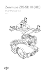
2.4.4.1 Configure a New Task in AutoPoll
A New Task in AutoPoll must be created to configure the PC modem, Serial port and the
Modbus properties in Autopoll. Select AutoPoll>Task>New from the main menu. Next
select your device – Radar.
Setting up the radar task properties
The Task properties window will appear after selecting your device. In the Connection
group box, select:
• Type= Modem
• Protocol=Modbus
APPLICATION NOTE
11
Using the SUTRON RADAR LEVEL CONTROLLER (RLR-0002-1) with a MULTI-MODEM GPRS
(Wireless Modem MTCBA-G-F4)
Modem Properties.
Clicking the (…) button next to the Type field opens the PC modem properties window.
Enter your GSM data phone number.
Click Port Settings button. Enter the settings below. Click OK when finished to return to
the Task Properties window.
• Com port: Com port where the PC modem is connected
• Baud Rate: 9600
• Data Bits: 8
• Parity: None
• Stop bits: 1
• Flow control: None
APPLICATION NOTE
Using the SUTRON RADAR LEVEL CONTROLLER (RLR-0002-1) with a MULTI-MODEM GPRS
(Wireless Modem MTCBA-G-F4)
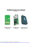
2.4.4.2 Modbus Master Properties
In the Radar Task Properties window, click the (…) button next to the Protocol. The
Modbus Master Properties window.
Enter the settings below:
• Device ID: Should be the same device ID that we select in the radar
configuration.
• Protocol: RTU
• Slave timeout: 5000
12
APPLICATION NOTE
13
Using the SUTRON RADAR LEVEL CONTROLLER (RLR-0002-1) with a MULTI-MODEM GPRS
(Wireless Modem MTCBA-G-F4)
2.5
2.6 CONNECTING GSM MODEM TO THE RADAR
After the radar sensor and GSM modem have been configured, we use the RS-232 interface to
connect the radar to the wireless modem using a NULL MODEM CONNECTOR.
2.7
2.8
TESTING MODEM WITH RADAR LEVEL SENSOR
2.8.1 COMMAND-LINE INTERFACE
This example will show you how to test GSM modem with the Radar Level Sensor (RLR-00021). We use a HyperTerminal session in Windows to communicate with the GSM modem
connected to the RLR-0002-1 sensor.
In one side you should have the RLR-0002-1 sensor connected to the GSM modem (See
configuration in COMMAND LINE INTERFACE section, page 7) and in the other side your PC
connected to a phone line.
First you have to start a Hyper Terminal session on Windows as follows: Start > Programs >
Accessories > Communication > Hyper Terminal. This will show this window.
APPLICATION NOTE
14
Using the SUTRON RADAR LEVEL CONTROLLER (RLR-0002-1) with a MULTI-MODEM GPRS
(Wireless Modem MTCBA-G-F4)
Then, in the Connect To window enter the data GSM modem phone number and click OK. After
this, click Dial and you will connected and ready to retrieve data from the RLR-0002-1 sensor.
The command prompt symbol (>) will appear in the HyperTerminal window. This shows that
you are connected with the GSM modem. In this example we type the HELP command for
illustration.
A list of command-Line commands is provided in the APPENDIX A at the end of this
application note.
2.8.2 MODBUS INTERFACE
We are going to use an example to test the GSM modem with the radar level sensor. In this
example we use AutoPoll program to retrieve log data from the radar level sensor connected to a
GSM modem. The configuration for the equipment is in MODBUS INTERFACE section (page.
8).
At this point, in one side the radar level recorder sensor should be connected to the GSM modem
and in the other side AutoPoll running in your PC (You must connect a phone line to the PC
modem).
AutoPoll in your PC will show as follow
APPLICATION NOTE
15
Using the SUTRON RADAR LEVEL CONTROLLER (RLR-0002-1) with a MULTI-MODEM GPRS
(Wireless Modem MTCBA-G-F4)
This indicated that your connection with the GSM modem is OK. Then, you can click over this
task and then right click to select Run Now. AutoPoll will star to retrieve data (.LOG file) from
the Radar Level Recorder sensor.
The status field in the AutoPoll window will show you the record number and the total bytes that
are downloading. If you want to see the retrieved data, browse for the .CSV file (the default path
is My Documents / Radar.csv)
3. APPENDIX A : COMMAND LINE INTERFACE:
3.1
List of commands
BATT +
Shows the current battery reading.
DIAG + 0
Shows system diagnostics, including system resets. If followed by 0, it will clear system resets.
DOWNLOAD
See LOG
EXIT
Quits command line.
HELP
Brings up the end user help (lists commands).
APPLICATION NOTE
16
Using the SUTRON RADAR LEVEL CONTROLLER (RLR-0002-1) with a MULTI-MODEM GPRS
(Wireless Modem MTCBA-G-F4)
HI
System replies with “Hello”
LAST +
Shows the last auto measured reading.
LOG
This command is used to download the log. It can be followed by optional parameters indicating what part
of the log to download.
LOG with no parameters will download since last.
“LOG ALL” gets whole log.
“LOG X” gets X last days ("LOG 3" gets last 3 days worth of data)
“LOG timeStart” gets data since provided date
“LOG timeStart timeEnd” gets data between provided dates
time can be YYYY/MM/DD HH:MM:SS or YYYY/MM/DD or HH:MM:SS
e.g. "LOG 12:00:00 13:00:00"
e.g. "LOG 2006/01/20 12:00:00 2006/01/21 12:00:00"
The file name for the downloaded log has the format
Stationname_log_YYYYMMDD.csv where YYYYMMDD is the date of the first data in the log
file
The data in the log file consists of some header lines to document important station information followed
by data. The following are examples of the header lines :
Station Name, WDID, model and version, Measuring Point, Operating Mode, Avg Time, DQAP, Sample Form Period
Sutron Radar, 20003, RDR ver. 1.11, 48.24659 feet, Normal, 10.000 sec, Disabled, 1.0 sec
PWM Slope, Factory Offset, SigStrCal
0.75743, -2.216, 3.195
Discharge, Equation, Parshall Flume Width, Weir Coefficient W, Coefficient A, Coefficient B, Gauge Height Shift
Enabled, Generic: A*(Stage^B), 12 inches, 1, 1, 1.5, 0.1
The header lines are followed by data in the following format:
Name, Date, Time, Value, Units, Quality
The following are examples of the logged data:
Display On, 8/9/2007, 17:20:37
Display Off, 8/9/2007, 17:25:52
Stage, 8/9/2007, 17:30:00, -23.2459, feet
Setup Change, 8/9/2007, 17:30:40
Before Cal, 8/9/2007, 17:30:40, -23.2466
After Cal, 8/9/2007, 17:30:40, 25
Stage, 8/9/2007, 17:45:00, 24.9958, feet
Stage, 8/9/2007, 18:00:00, 24.9963, feet
Stage, 8/9/2007, 18:15:00, 24.9994, feet
Stage, 8/9/2007, 18:30:00, 25.006, feet
Stage, 8/9/2007, 18:45:00, 24.9952, feet
Stage, 8/9/2007, 19:00:00, 25.0002, feet
Bringing the Benefits of Real-Time Data Collection to the World 32
APPLICATION NOTE
17
Using the SUTRON RADAR LEVEL CONTROLLER (RLR-0002-1) with a MULTI-MODEM GPRS
(Wireless Modem MTCBA-G-F4)
LOG HELP
Shows details on how to use the download command.
STAGE = 14.5
Changes the current stage to 14.5 (of whatever units are currently chosen). User can choose any number,
not just 14.5. Please see the section Setting Stage on page 13.
MEAS +
Initiates, waits for, and shows the results of sensor measurements.
REBOOT
Does a software resets of the system.
RESETS + 0
Shows system diagnostics, including system resets. If followed by 0, it will clear system diagnostic status.
SETUP
If provided without any other parameters, it lists all setup details. That includes each setup variable and its
current value.
Can be followed by a setup variable name and a new value for that variable.
E.g. “CHANGE STATION NAME = SUTRON”
If SETUP DEFAULT is issued, it will reset the entire setup to defaults.
STATUS 0
Shows system status including time, boot time, battery readings, last Radar measurements, current onboard
sensor readings, and any hardware errors that may exist. If followed by 0, it clears the hardware errors.
TIME
Shows the current system date and time. If followed by a new time, it changes the system time.
UPG +
Initiates a system software upgrade. It needs to be followed by the YModem transfer of an .upg file specific
to the product. Both the main application and the bootloader are upgraded this way (but each needs its own
.upg file).
VER +
Shows the current software version, including build date and time and the bootloader version.
4. APPENDIX B : CABLING
4.1 RLR-0002-1 (DB9 Connector)
The radar level sensor comes with a DB9F connector for connection to RS-232 devices. The
DB9F can be connected to the serial port on most PCs using a straight cable. A null modem
adapter is needed to connect to most PDAs and modems. This connector allows for access to the
command line interface using a terminal program. Some modems and radios can be connected to
this port. A logger can be programmed to use this port. The following table shows the pin
assignments of the DB9F connector.
DB9F Pin
Name
Notes
1
2
3
4
5
6
7
8
9
N/C
RXD
TXD
DTR
Ground
N/C
RTS
CTS
VOUT
No Connection
Data from Radar
Data to the radar
Signal to the radar
No Connection
Request to Send, signal to the radar
Clear to Send, signal from the radar
Jumper selectable for 5V or VBAT (100ma max)
APPLICATION NOTE
Using the SUTRON RADAR LEVEL CONTROLLER (RLR-0002-1) with a MULTI-MODEM GPRS
(Wireless Modem MTCBA-G-F4)
18
APPLICATION NOTE
19
Using the SUTRON RADAR LEVEL CONTROLLER (RLR-0002-1) with a MULTI-MODEM GPRS
(Wireless Modem MTCBA-G-F4)
4.2
MTCBA-G-F4 (RS-232 15-Pin Connector Pinout)
The Wireless Modem has a DE15-serial connector incorporated which includes a RS-232 interface link, audio link,
Boot and reset. This connector allows for access to the command line interface using a terminal program such as
HyperTerminal of Windows. The following table shows the pin assignment.
RS-232
Audio
Boot
Reset
PIN
EIA
CCIT
Designation
1
DCD
RX
TX
DTR
GND
DSR
RTS
CTS
RI
MIC (+)
MIC(-)
SPEAKER(+)
SPEAKER(-)
BOOT
RESET
109
104
103
108.2
Data Carrier Direct
Receive Data (out)
Transmit Data
Data Terminal Ready
Signal Ground
Data set ready
Request to Send
Clear to Send
Ring Indicator
6
2
8
9
7
12
11
13
4
5
10
15
3
14
107
105
106
125
For factory use only
To reset, connect toGND
momentarily
(Typical: 2mSec). Open for normal
operation.