1
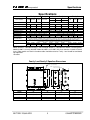
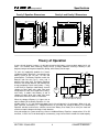
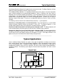
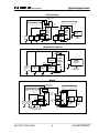
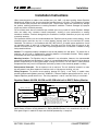
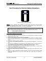
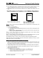
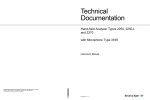
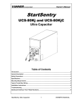
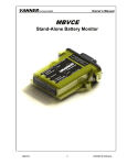
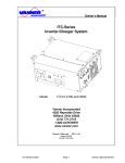
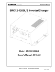
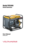
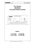
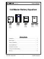
Owner’s Manual
Incorporated
VoltMaster Battery Equalizer
24 V
Family 1
60-10B
60-20A
60-50A
60-50E
60-50M
12 V
G ND
Family 2
60-100C
60-100D
60-100E
Family 3
60-60
60-60M
60-80
60-100
Family 4
65-60
65-60M
65-80
65-100
Family 5
66-60
66-80
66-100
Table of Contents
Introduction………………………………………………….………………… 2
Specifications…………………………………………………….………….… 3
Theory of Operation……………...…………………………………………… 4
Typical Applications…………………………...…………….…………..…… 5
Installation Instructions………………………….………...…………………. 7
Testing and Troubleshooting………………………………………………… 9
Warranty……………………………………………………………………….. 15
BATTERY EQUALIZER
1
OWNER’S MANUAL
Owner’s Manual
Incorporated
Introduction
Thank you for purchasing a Vanner VoltMaster Battery Equalizer. We are confident that you will be very
pleased with its performance because our Battery Equalizers are designed and manufactured by skilled
professionals using the highest standards in workmanship. With minimum maintenance and care, you can
be assured of many years of trouble free service.
General Description
The Vanner VoltMaster Battery Equalizer is an efficient and highly reliable method of obtaining a 12 volt
DC power source from a 24 volt DC electrical system. The equalizer makes the batteries look like they
are in series and parallel at the same time. In addition to providing regulated 12 volt power, the system
ensures that battery voltages remain equal which significantly extends battery life. Ideally suited for
vehicle and alternate energy applications, the VoltMaster Battery Equalizer is designed to save your
batteries and the money you would spend replacing them. Users of the Vanner VoltMaster Battery
Equalizer know that it is the most cost effective and dependable solution for dual voltage systems.
A typical system would include a 24VDC power source, such as an alternator or solar array, two 12 volt
battery banks in series, and the VoltMaster Battery Equalizer. The Battery Equalizer connects to the 24
volt, 12 volt and ground terminals of the battery system. When the 12 volt loads require power, the
Battery Equalizer ensures that the current is taken equally from both batteries, and that the voltages of
the two batteries are kept equal. This equalization ensures extended battery life and provides a stable 12
volt supply for operating accessories.
Parallel Equalizers: Models are available which provide 10, 20, 60, 80 and 100 amps of 12 volt DC
power. VoltMaster Battery Equalizers may also be operated in parallel to provide more power. For
example, two 60 amp units can be installed to provide 120 amps of 12 volt DC power. Family 1, Family 3,
Family 4, and Family 5 models may be paralleled in any combination. Family 2 models may be paralleled
only with other Family 2 models.
NOTE: The Vanner VoltMaster Battery Equalizer is an extremely reliable device and, when installed
according to the instructions, will provide reliable operation for an indefinite period of time. However, if a
system abnormality should develop that would cause a Battery Equalizer malfunction, damage to the
battery system could result if 12 volt loads are present. If your system application is critical you may
consider installing a Vanner Model EM-70 Electrical System Monitor. This module monitors the battery
system's voltages and balance, and provides fault signals that can be wired to warning lights, buzzers or
other control/warning devices. Models 60-50M , 60-60M and 65-60M have the EM-70 built in. Call Vanner
for more details.
BATTERY EQUALIZER
2
OWNER’S MANUAL
Specifications
Incorporated
Specifications
Family 1
Model Number
Input Voltage 24v
Efficiency (Peak)
Max 24v Input Amps
Output Voltage
Output Amps (12v)
Standby Current
Operating Temp.
Storage Temp.
Serviceable
Environmental
Considerations
Mounting Location
Weights
60-10B
>91%
60-20A
Family 2*
60-50A*
60-100E*
20 to 35v
>92%
>92%
6
12
Family 3* / Family 4
60-60*
60-80*
65-60
Family 5
60-100*
65-80
65-100
66-60
18 to 36v
>94%
>97.5%
18 to 32v
>97.5%
>97.5%
>97%
55
32
43
53
32
28
66-80
66-100
18 to 32 v
>97%
>97%
43
53
(Input Voltage/2) ±2% - 50mv
0-10
0-20
0-50
0-100
0-60
0-80
0-100
0-60
0-80
17 milliamps nominal at 28.4V
-40°C to +71°C (-40°F to 160°F)
-40°C to +75°C (-40°F to 167°F)
-54°C to +85°C (-65°F to 185°F)
-54°C to +95°C (-65°F to 203°F)
Yes
Yes
Yes
Yes
No
No
No
No
No
0-100
No
Anodized aluminum enclosure provides protection against salt, fungus, dust, water, fuel vapors and all fluids associated
with commercial and off-highway vehicle operations. Continuous exposure to splashes and spills should be avoided.
Mount on a flat surface close to the batteries to allow short cable runs. Vertical mounting with terminals down is
recommended. Location should be protected from battery acid and gases.
2.3 lbs
5.0 lbs
7.0 lbs
9.5 lbs
6.0 lbs
6.6 lbs
6.6 lbs
6.0 lbs
7.0 lbs
7.6 lbs
7.6 lbs
6.3 lbs
6.3 lbs
Unlisted models: Model 60-60M and 65-60M have built-in EM-70 Electrical System Voltage Monitor.
Model 60-50M is a 60-50A with built-in EM-70. Model 60-50E is a 60-50A with weather resistant gasket.
Model 60-100C is an early 60-100E. Model 60-100D is a 60-100C with circuit breakers instead of internal
fuses. Older models not listed in the above table should be tested as Family 1 and should be considered
non-repairable.
*Obsolete.
Family 1 and Family 2 Equalizer Dimensions
FA M IL Y 1: 1/4"-2 8 S TU D (X 3)
TO RQ U E 60 IN-LB S M A X.
"B "
"C "
"D "
FA M IL Y 2: 3/8"-2 4 S TU D (X 3)
TO RQ U E 150 IN-LB S M A X.
GND
8.50"
(216.0)
+1 2V
8.00"
(203.3)
7.40"
(188.0)
+2 4V
.25" (6.35)
.25" (6.35)
"A "
Model
60-10B
60-20A
60-50A
60-100C
“A”
4.25 (107.9)
9.38 (238.2)
13.38 (339.8)
13.46 (341.88)
BATTERY EQUALIZER
“B”
3.00 (76.3)
8.00 (203.2)
12.00 (304.8)
12.00 (304.8)
3
3.20"
(81.3)
3.82"
(97.03)
“C”
2.00 (50.80)
4.50 (114.3)
8.00 (203.2)
8.00 (203.2)
“D”
0.50 (12.7)
1.75 (44.4)
2.00 (50.8)
2.00 (50.8)
OWNER’S MANUAL
Specifications
Incorporated
Family 3 Equalizer Dimensions
9.00"
(228.7)
.50"
(12.7)
8.00"
(203.3)
Family 4 and Family 5 Dimensions
2.50"
(63.5)
8.00
(203.2)
10.50
(255.6)
9.13
(231.7)
0.56
(14.3)
2.47
(62.74)
+24V
8.50"
(216.0)
GND
7.94
(201.7)
8.00"
(203.3)
8.50
(215.9)
+12V
.25"
(6.35)
5-16"-18STUD(X3)
TORQUE120 IN-LBSMAX.
0.28
(7.1)
5-16"-18 STUD (X3)
TORQUE 120 IN-LBS MAX.
___________________________________________________________________
Theory of Operation
In many 24 volt electrical systems it is desirable to tap into the battery system to obtain power for 12 volt
loads. This method, while seemingly simple, causes a charge imbalance resulting in Battery B (see
diagram) being overcharged, and possibly boiling, while Battery A discharges.
To solve this application problem the Vanner
VoltMaster Battery Equalizer is connected to the
battery system at the +24 volt, +12 volt, and
ground points. The Battery Equalizer makes the
batteries look like they are in series and in
parallel at the same time. The Battery Equalizer
maintains the voltage balance and therefore the
charge acceptance rate of each battery. Family
3 and Family 4 Equalizers hold Battery A and B
voltages to within 0.05 volts under light loads
and to within 0.1 volts at full rated load. Family 1
and Family 2 models hold Battery A and B
voltages to within 0.10 volts under light loads
and to within 0.50 volts under full rated load.
+24V
+
12V
Battery B
+12V
+
24V
ALT.
+24 Volt
Loads
+12 Volt
Loads
F2
+24V
VANNER
Battery
Equalizer
F1
+
12V
Battery A
-
+12V
GND
_
Note-Battery Banks A and B should
have the same amp-hour capacity.
When the voltage of Battery A is higher than or
equal to Battery B the Battery Equalizer is in the
standby mode, i.e., it is not transferring power from its 24 volt input to its 12 volt output. When a 12 volt
load is present, and Battery A's voltage decreases to just below the voltage of Battery B, the Battery
Equalizer activates and transfers sufficient current from Battery B to Battery A to satisfy the load and
maintain an equal voltage and charge in both batteries.
A key advantage of a system containing a Vanner VoltMaster Battery Equalizer, compared to a DC to DC
converter, is that if the 12 volt load requires a momentary surge current which exceeds the rated capacity
BATTERY EQUALIZER
4
OWNER’S MANUAL
Typical Applications
Incorporated
of the Battery Equalizer, Battery A will supply the extra current to the load. The Battery Equalizer will then
replenish the energy to Battery A after the surge has passed.
The VoltMaster Battery Equalizer is a completely automatic device that requires no human intervention
when installed according to the recommended procedures. Family 1 Equalizers and some Family 2
Equalizers have a manually resetable circuit breaker. If the circuit breaker trips, due to a system overload
or abnormality, it can be reset by pushing the white button. Note that on some units the white circuit
breaker button may protrude slightly in its normal (non-tripped) position. A blown fuse on Family 2
Equalizers requires factory repair. There are no user operational devices on Family 3, Family 4 or Family
5 models.
The following scenarios describe the VoltMaster Battery Equalizer's system operation.
Scenario #1 - 24 volt load present, no 12 volt load present. The system operates as a system would
without the Battery Equalizer whether the alternator is ON or OFF. The Battery Equalizer is in the
standby mode except for making small adjustments to keep the batteries in balance.
Scenario #2 - Both 24 volt and 12 volt loads present, alternator is OFF. The Battery Equalizer will
insure that both batteries will discharge at the same rate even if different loads are present.
Scenario # 3 - Both 24 volt and 12 volt loads present, alternator is ON. The alternator provides 24
volt power to the battery system and to the 24 volt loads. The Battery Equalizer transfers power from the
24 volt source to the 12 volt load by converting 24 volt power to 12 volts. It will supply sufficient 12 volt
power to satisfy the 12 volt load and to maintain battery voltage balance.
_____________________________________________________________________
Typical Applications
Vanner VoltMaster Battery Equalizer are used in many types of applications including transit and tour
buses, private coaches, heavy trucks and off highway equipment, yachts, and alternative energy systems
such as solar powered homes. In addition to Battery Equalizers, Vanner manufactures a wide range of
complementary products such as DC to DC converters, DC to AC inverters, battery charger/conditioners,
and battery isolators. The following system diagrams illustrate how these products are used in various
applications.
TRANSIT BUS
+24V
+
12V
Battery B
+12V
+
24V
ALT.
+24 Volt
Loads
+12 Volt
Loads
F2
+24V
VANNER
Battery
Equalizer
F1
+
12V
Battery A
-
+12V
GND
_
BATTERY EQUALIZER
5
OWNER’S MANUAL
!
Typical Applications
Incorporated
PRIVATE COACH
Battery Isolator or
Paralleling Switch
HOUSE BATTERY SYSTEM
COACH BATTERY SYSTEM
+24V
F2
F2
+24V
+24V
+
12V
Battery B
+12V
+
+24 Volt
Loads
24V
ALT.
F1
+12V
+12V
+
12V
Battery A
-
+12 Volt
Loads
+
12V
Battery B
-
VANNER
Battery
Equalizer
GND
+12 Volt
Loads
_
F1
+24V
VANNER
Battery
Equalizer
+
12V
Battery A
-
+
-
+12V
GND
VANNER
DC to AC
Inverter
120VAC
To AC Loads
TOUR/CHARTER COACH
+24V
F2
+24V
+
12V
Battery B
+12V
+
+24 Volt
Loads
24V
ALT.
VANNER
Battery
Equalizer
+
F1
+12 Volt
Loads
-
+12V
+
12V
Battery A
-
VANNER
DC to AC
Inverter
GND
120VAC
To AC Loads
_
MARINE
Battery Isolator or
Paralleling Switch
ENGINE BATTERY SYSTEM
HOUSE BATTERY SYSTEM
+24V
F2
F2
+24V
+
12V
Battery B
+
+
24V
ALT.
24V
Starter
_
_
+12V
+12 Volt
Loads
F1
+
12V
Battery A
-
+24V
VANNER
Battery
Equalizer
+12V
GND
To 24V
House
Loads
To 12V
House
Loads
+
12V
Battery B
F1
+
12V
Battery A
-
+24V
VANNER
Battery
Equalizer
+12V
GND
+
-
VANNER
Battery
Charger
From Main
AC Panel
+
VANNER
DC to AC
Inverter
To Automatic
Transfer
Switch
Engine Controls
Navigation Systems
Communications Equip.
BATTERY EQUALIZER
6
OWNER’S MANUAL
"#$$%&
Installation
Incorporated
Installation Instructions
When connecting wires or cables to the available post (+24, GND, +12) when installing Vanner Equalizer
Models 60-60, 60-80, 60-100, do not exceed the specified torque of 120 in-lbs. This information is printed
on the Product Label just above the connection post. Torque values higher than specified may damage
the product, reducing performance or creating hazardous conditions. Products damaged by improper
torque may not be covered by warranty.
Do not connect more than one conductor per available post on any model of Vanner Equalizer. Multiple
wires and cables may overstress internal components, resulting in poor performance or creating
hazardous conditions. Products damaged by the installation of multiple conductors per post may not be
covered by warranty.
Fault protection devices must be installed between the Equalizer and the power source (battery). A fault
protection device would be any fuse or circuit breaker properly rated for the maximum DC current
obtainable. This advisory is in accordance with SAE, NEC and UL, for mobile power applications. Install
per applicable codes or within 18” of the battery. See Wire and Fuse Sizing Chart on page 9 of this
manual or contact Vanner at 1-800-227-6937 or [email protected] if assistance is needed in sizing
fault protection devices.
Caution: This equipment employs components that tend to produce arcs and sparks. To prevent fire or
explosion, do not install in compartments containing batteries or flammable materials. Safety goggles
should always be worn when working near batteries
Mounting Location –The Equalizer may be mounted in any orientation, however, the recommended
orientation for optimum heat dissipation is vertical. It is recommended that the wiring terminals be down to
prevent the possibility of a falling metal object shorting the terminals. Do not mount in zero-clearance
compartment that may result in the Equalizer overheating. Locate so that contact by people is unlikely.
Environmental Protection – Do not expose to rain or moisture. The unit should be located in an area
that will protect it from direct exposure to moisture such as high pressure washing, rain, etc.
Wiring Sequence– To prevent reverse polarity damage on Family 1 and Family 2 models when
connecting/disconnecting battery terminals: ALWAYS 1) Remove Equalizer ground terminal first, and 2)
Replace Equalizer ground terminal last. The wiring sequence is not an issue with Family 3 or 4 models.
Equalizer Models 60-50M, 60-60M and 65-60M with built-in EM-70 Battery Monitor
F2
+2 4 V
(W H T ) +2 4 V IG N .
R E D (B A T T . B A L .)
B L K (B A T T . H I)
G R N (B A T T . LO )
+ VO LT AG E FO R LAM PS
GND
+1 2 V
2 4V
- BATT A +
F1
- BATT B +
O P TIO N A L
LO AD
LOA D
D IS C O N N E C T
S W ITC H E S
B A TTE R Y M O N ITO R
+
2 4V A L T
-
C O N T R O L IN P U T : +2 4V D C
O U T P U T : 0 .3 7 5 A M P S (P E R T E R M .)
T R IP L E V E LS : (A L L H A V E 5 S E C . D E L A Y )
B A T T E R Y B A L A N C E IN P U T V O LT A G E .. 2V + /-6 %
B A T T E R Y S Y S T E M H IG H 3 0.3 V
B A T T E R Y S Y S T E M L O W 23 .7 V
1 2V
LO AD
The EM-70 Battery Monitor provides the following ground signals: Battery HI when +24 rises above
30.3V, Battery LO when +24 falls below 23.7V, Battery BALANCE when +12 is not within 6% of (+24 ÷ 2).
Each ground signal is rated 0.375 amps and should be protected by a 1 amp fuse.
BATTERY EQUALIZER
7
OWNER’S MANUAL
'())*+
Installation
Incorporated
Caution adding 12volt batteries
+24V
+
24V
ALT.
_
F2
+24V
+
VANNER
12V
Battery B Battery
Equalizer
+
12V
Battery A
-
+12V
GND
+24V
BATTERY A AND BATTERY B
ARE THE SAME SIZE.
+12V
F1
+
12V
Battery
-
+
12V
Battery
-
+24V
+
VANNER
12V
Battery B Battery
Equalizer
+
+
12V
Battery A
-
24V
ALT.
_
+12 Volt
Loads
BATTERY A AND BATTERY B
ARE NOT THE SAME SIZE.
+12V
GND
+12V
+
12V
Battery A
-
+
12V
+12 Volt
Battery A
Loads
UNACCEPTABLE- BATTERY B WILL BECOME
OVERCHARGED IF THE EQUALIZER CANNOT
KEEP UP WITH THE ALTERNATOR.
ACCEPTABLE - BATTERY A AND BATTERY B
ARE THE SAME SIZE.
In certain applications, such as private coach or alternate energy applications, it may be desirable to have
additional 12 volt “House Batteries” to operate heavy 12 volt (inverter) loads. Use the Equalizer to charge
the additional batteries.
Connect the Equalizer 12V terminal to the additional batteries only. Do not connect the Equalizer 12V
terminal to both battery banks as this would make Battery A larger than Battery B. Damage to Battery B
may occur during charging due to overcharging, if the equalizer cannot keep up with the charging
system.
Caution using a Ground-Side Battery Disconnect Switch
+24V
HIGH CURRENT DIODE
+12V
+
24V
ALT.
_
+24 Volt
Loads
+
12V
Battery B
F1
+
12V
Battery A
-
+12 Volt
Loads
(Radio)
F2
+24V
VANNER
Battery
Equalizer
+12V
GND
BATTERY DISCONNECT SWITCH
The system must be wired as shown to prevent Reverse Polarity Damage to polarity sensitive12 volt
loads and Family 1 and Family 2 Equalizers while the ground-side disconnect switch is open. The
equalizer'sGND terminal must be wired to the battery side of the ground-side disconnect switch circuit for
the equalizer to work properly.
Install the external High Current Diode, such as Vanner Model 52-75 (45 amp continuous rating) to
protect polarity sensitive 12 volt loads if these loads do not already contain input diode protection. This
prevents a reverse polarity on the 12 volt equipment when the battery switch is open. The reverse polarity
does not come from the Equalizer but from any 24 volt equipment that may be turned ON.
Wire Size and temperature rating
Cables connecting the Battery Equalizer to the batteries must be sufficiently large to prevent unwanted
voltage drops. These voltage drops (loss) must be less than 0.05 VDC between the Equalizer's +24 volt
terminal and the battery +24 volt terminal (Battery B positive terminal), less than 0.10 VDC between the
Equalizer's +12 volt terminal and the battery +12 volt terminal (the jumper between Battery A and Battery
BATTERY EQUALIZER
8
OWNER’S MANUAL
,-../0
Testing and Trouble Shooting
Incorporated
B), and less than 0.05 VDC between the Equalizer'sGND terminal and the battery ground terminal
(Battery A negative terminal that is connected to chassis ground). In most installations, the Battery
Equalizer's terminals are wired directly to the battery terminals to prevent voltage loss that could occur in
switch contacts, connections, and long wire runs. Since the equalizer can be operated in temperatures up
to 71º or 75ºC, use wire rated at least 90ºC. See Wire and Fuse Size Chart.
Wire and Fuse Size Chart
Wire
Size
AWG
#14
#12
#10
#8
#6
#4
#2
#1
#1/0
#2/0
Ring Terminal
Molex or UL
recognized
equal
191930072
191930134
191930134
191930157
191930251
191930278
191930309
191930333
191930333
191930346
Fuse F1
Fuse F2
Max wire length, in feet, between Equalizer and battery to keep voltage drop under 0.1
volt. The chart assumes wire carries no other load and wire temperature is below 80ºC.
60-10
60-20
60-50
3.2
5.0
7.7
12.8
19.4
35.2
51.9
65.4
82.9
105.5
20 amp
10 amp
XXX
2.5
3.8
6.4
9.7
17.6
26.0
32.7
41.4
52.7
30 amp
15 amp
XXX
XXX
XXX
2.6
3.9
7.0
10.4
13.1
16.6
21.1
80 amp
35 amp
60-60
65-60
66-60
XXX
XXX
XXX
2.1
3.2
5.9
8.7
10.9
13.8
17.6
80 amp
40 amp
60-80
65-80
66-80
XXX
XXX
XXX
XXX
2.4
4.4
6.5
8.2
10.4
13.2
100 amp
50 amp
60-100
65-100
66-100
XXX
XXX
XXX
XXX
XXX
3.5
5.2
6.5
8.3
10.5
125 amp
80 amp
2 x 60-100
2 X 65-100
2 X 66-100
XXX
XXX
XXX
XXX
XXX
XXX
2.6
3.3
4.1
5.3
250 amp
150 amp
Crimp the ring terminals using Molex tool 192840002 (14ga), 192840001 (10 -12ga), 192840035 (2 - 8ga) (phone
813-521-2700) and AC Terminal tool model 0280 (6 ga and larger) (phone 614-868-9828).
___________________________________________________________________
Testing and Troubleshooting
All Vanner equalizers fall into one of three distinct families. The three families operate differently and
must be tested differently. The following three test procedures apply only to the equalizer family listed.
Before testing the equalizer, be sure all battery connections are good and that fuses F1 and F2 are good.
CAUTION
Servicing of electrical systems should only be performed by trained and qualified technical personnel.
Equipment Required
VoltMeter having 0.01 volt resolution. (Fluke Model 87 Multimeter recommended).
Clamp-on amp meter (Fluke Model 36 Clamp-on Meter recommended).
Vanner Repair Service
Vanner offers a quick turn around factory repair service for Family 1 and Family 2 models. (Family 3, 4
and 5 models are non-repairable.) Send the unit to the address below with a note instructing us to repair
it. Include your name, phone number, shipping address (not a P.O. Box Number), and your purchase
order number.
BATTERY EQUALIZER
9
OWNER’S MANUAL
123345
Testing and Trouble Shooting
Incorporated
Test Procedure for Family 1 Battery Equalizers
Models 60-10B, 60-20A, 60-50A
CAUTION
To avoid Reverse Polarity Damage to Family 1 and Family 2 Equalizers when servicing the electrical
system or when performing any work which involves making battery connections always:
1. Remove Equalizer Ground terminal first.
2. Replace Equalizer Ground terminal last.
Family 1 Battery Equalizer Test Procedure:
1. Carefully remove the ground (GND) cable from the Equalizer. Do not allow this cable to touch any
other connection on the Equalizer because the other terminals are connected to the batteries.
2. Make sure there is approximately 12 volts between the +24 and +12 terminals of the Equalizer by
momentarily connecting the two terminals of a 12 volt light (headlight, marker light, etc.) to the +24
and +12 terminals of the Equalizer. The light should light and stay lit.
3. Next, connect that same 12 volt lamp between the +12 and GND terminals of the Equalizer. The lamp
should light and stay lit. If the lamp does not light, the light then goes out, or the light dims, the
Equalizer requires repair.
4. Further verification may be made by measuring the voltages on the Equalizer terminals. Be certain
that the lamp used earlier is connected between the +12 and GND terminals.
5. Measure the voltage between +24 and +12 terminals. Note this reading.
6. Measure the voltage from the +12 terminal to GND. Note this reading.
7. Compare the two readings by subtracting the +12 to GND reading from the +24 to +12 reading. A
properly functioning Equalizer is one where the difference is between -0.5 and +0.13 volts. For
example, the +24 to +12 reading might be 12.85 volts. The +12 to GND voltage might read 12.75
volts. This Equalizer would be functioning properly with a 0.10 difference (12.85 minus 12.75 volts)
which is within specs.
Common Questions for Family 1 Battery Equalizers
Q)
Will operating loads which exceed the output rating of the Battery Equalizer cause the circuit
breaker (white button near the wiring terminals on Family 1 or Family 2 equalizers) to trip?
BATTERY EQUALIZER
10
OWNER’S MANUAL
67889:
Testing and Trouble Shooting
Incorporated
A)
No, the Battery Equalizer electronically limits the output current to a value less than the amount
required to trip the circuit breaker. (Extreme conditions, such as 28 VDC input with 8 VDC output
at very high ambient temperatures, may cause the circuit breaker to trip.)
Q)
Why is the Battery Equalizer's circuit breaker value lower than its output current rating (35 amp
circuit breaker in model 60-50A)?
A)
The circuit breaker is in the ground circuit. Due to the equalizer’s two to one (24/12 VDC) voltage
conversion, the model 60-50A requires 25 amps at 24VDC input to produce about 50 amps
output at 12 VDC. Therefore, a 35 amp circuit breaker in the GND circuit will properly protect for
the maximum 25 amp rating.
Q)
What causes the circuit breaker to trip on a Battery Equalizer?
A1)
The Battery Equalizer's circuit breaker is designed to trip when the +12 volt toGND terminals are
exposed to reverse polarity.
A2)
With the Battery Equalizer'sGND terminal connected to chassis and the battery negative terminal
disconnected, a short between a +24 volt circuit and chassis will pull the chassis up to +24 volts,
causing a reverse polarity on the +12 volt to GND circuits. The circuit breaker trips to protect the
Battery Equalizer.
A3)
With the Battery Equalizer'sGND terminal connected to chassis and the battery negative cable
disconnected, 24 volt loads (e.g., starter motor) will pull the chassis up to +24 volt causing a
reverse polarity on the Battery Equalizer's +12 Volt toGND circuits. The circuit breaker will trip to
protect the Battery Equalizer.
A4)
Since the above reverse polarity conditions may occur during bus maintenance it is
recommended that the service personnel verify the circuit breaker is IN before releasing the bus
for service and the tour bus operator do the same in his “walk around”.
Q)
What are some known conditions that could cause Battery Equalizer problems?
A1)
Corrosive liquids or water forced into the Battery Equalizer's case from high pressure spray
cleaning could shorten the normal life expectancy.
A2)
Drilling into the case (except for the mounting flanges) can shorten the life or prevent the unit
from operating. The installer may not realize the Battery Equalizer is not operating correctly
unless a 12 volt load is applied to the system and the Battery Equalizer 12 volt current is
measured.
A3)
Too small of wire or bad connections will allow the Battery balance to be less than optimum.
Voltage loss in wire from the battery's +24 volt terminal to the Battery Equalizer's +24 volt
terminal should be 0.05 VDC maximum; from the battery's +12 volt terminal to the Battery
Equalizer's +12 volt terminal should be 0.10VDC maximum, and from the battery ground terminal
to the Battery Equalizer'sGND terminal should be 0.05 VDC maximum, when the +12 volt load is
causing the Battery Equalizer to operate at 100% capacity.
A4)
Installing the Battery Equalizer in a location where it will be exposed to battery fumes will shorten
its normal life. Acid fumes are heavier than air. Installation of Battery Equalizers on the battery
mounting surface near the bottom of the batteries have caused severe corrosion to the Battery
Equalizers. However, installation of Battery Equalizers 3 or more inches above the top of the
batteries have not caused problems.
Q)
Can different models of equalizers be paralleled?
A)
Yes, any combination of models from Family 1, Family 3 and Family 4 may be paralleled. Family
2 models may only be paralleled with other Family 2 models.
BATTERY EQUALIZER
11
OWNER’S MANUAL
;<==>?
Testing and Trouble Shooting
Incorporated
Test Procedure for Family 2 Battery Equalizers
24V
12V
GND
Models 60-100C, 60-100D and 60-100E
General: Family 2 Equalizers were designed to be more energy conservative during low power
requirements compared to Family 1 models. This along with unique protection circuitry require Family 2
models to be tested differently than Family 1, or Family 3, 4 and 5 models.
CAUTION
To avoid Reverse Polarity Damage to Family 1 and Family 2 Equalizers when servicing the electrical
system or when performing any work which involves making battery connections always:
1. Remove Equalizer Ground terminal first.
2. Replace Equalizer Ground terminal last.
Family 2 Battery Equalizer Test Procedure:
1. With the coach engine and vehicle loads OFF measure the voltage of Battery A. Replace or recharge
Battery A if less than 11.5 volts.
2. Start the engine and turn ON a 12 volt load such as headlights.
3. Measure the input voltage between the +24 and GND posts of the equalizer. This voltage should be
between 25.5 volts and 29.0 volts. If it isn’t then check the alternator and 24 volt voltage regulator
circuits.
4. Zero the DC Clamp-on ammeter as needed.
5. Put the jaws of the clamp-on ammeter around all wires connected to the equalizer +12 volt terminal
stud.
6. Observe the DC amperage out of the equalizer with the clamp-on ammeter. If there are 3 amps or
more showing on the ammeter, the equalizer is functioning and no further tests are needed.
7. Continue with the following steps ONLY if the ammeter shows less than 3 amps.
8. Measure the voltage between the +24 terminal (meter positive lead) and the +12 terminal (meter
negative lead) of the equalizer. Record this voltage.
9. Subtract 0.60 volts from the number recorded in Step 8.
10. Measure the voltage between the equalizer +12 terminal (meter pos) and the GND terminal (meter
neg).
11. Wait for this voltage to drop below the voltage calculated in Step 9 or the clamp-on ammeter reading
jumps from approximately 0 to more than 3 amps. More than 3 amps means the equalizer is
functioning.
BATTERY EQUALIZER
12
OWNER’S MANUAL
@ABBCD
Testing and Trouble Shooting
Incorporated
12. If the voltage drops below the calculated value from Step 9 and the clamp-on ammeter has not
jumper from approximately 0 to more than 3 amps of current wait for an additional 30 seconds.
13. If the equalizer does not turn ON after 30 seconds the unit is defective and should be sent in for
repair.
Test Procedure for Family 3, 4 & 5 Battery Equalizers
Models 60-60, 60-80 and 60-100
Models 65-60, 65-80, 65-100
Models 66-60-66-80, 66-100
General: Family 3, Family 4 and Family 5 Equalizers contain an indicator light. If the indicator light is ON
the equalizer is working.
The Equalizer is working properly if:
1. The Indicator Light is ON and;
2. The 12 volt DC loads are being operated continuously and are within the rated capacity of the
equalizer and;
3. Battery A voltage is lower than Battery B by no more than 0.05 to 0.10 volts (measured at the
equalizer +24, +12 and GND terminals).
Family 3, 4 and 5 Battery Equalizers are electronically protected against reverse polarity damage
therefore the DC connection sequence is not an issue.
Family 3, 4 and 5 Equalizers will not function properly unless all three battery connections are made.
Battery A and Battery B voltages both must be above 8 volts for the unit to turn ON.
Any combination of Family 1, Family 3, Family 4 and Family 5 models may be operated in parallel.
Please note that the 24V, 12V and GND stud position and orientation are different on Family 3, 4 and 5
models than on Family 1 or Family 2 models.
Family 3, Family 4 and Family 5 Battery Equalizer Test Procedure:
1. Field test the equalizer while fully connected to the vehicle batteries. For bench testing, two 12 volt
batteries, or two 12 volt power supplies are required. Family 3, 4 and 5 Equalizers must be connected
to the batteries at GND, 12V and 24V to function properly.
2. If battery voltage is below 24 volts start the vehicle or apply a 24 volt battery charger to the batteries.
3. Turn ON 12 volt DC loads up to the equalizer rated capacity. Measure DC amps on the equalizer +12
cable to verify load amperages.
4. At the equalizer measure and record:
a. Battery A voltage (voltage between the equalizer +12 and GND terminals)
b. Battery B voltage (voltage between the equalizer +24 and +12 terminals)
c. Equalizer Indicator Light status (ON or OFF)
BATTERY EQUALIZER
13
OWNER’S MANUAL
EFGGHI
5.
Subtract Battery A voltage from Battery B voltage and compare readings.
Voltage Comparison
a.
b.
c.
d.
e.
Testing and Trouble Shooting
Incorporated
Battery A is lower than Battery B but
within 0.05 volt.
Battery A is lower than Battery B by
0.05 to 0.10 volts.
Battery A is lower than Battery B by
more than 0.10 volts
Battery A is lower than Battery B by
more than 0.10 volts
Battery A is higher than Battery B
Indicator
Light
Equalizer Status
OFF
OFF
ON
ON
ON
ON
OFF
OFF
Stand-by Mode.
The equalizer will not turn ON until Battery A is
lower than Battery B by more than 0.05 volts.
Normal Operating Mode
Self-Protection Mode due to Overload
Condition. See below.
The Equalizer is not functioning
properly.
Abnormal condition. Suspect Battery B is defective or a 12 volt load
is connected to Battery B.
Overload Condition on Family 3, Family 4 and Family 5 Equalizers
An overload condition exists when the 12 volt loads exceed the equalizer’s rated capacity. The overload
condition will not damage the equalizer but may cause damage to the batteries.
During the overload, the equalizer output is limited by internal protection circuits to its Rated Output
Amps. The 12 volt amps exceeding the equalizer output are drawn from Battery A which will begin to
draw the batteries out of balance. The equalizer full Rated Output Amps are maintained as long as
Battery A and Battery B remain balanced within 0.10 volt. The internal protection circuits will reduce
equalizer output as the batteries become further out-of-balance. If Battery A voltage falls below
approximately 8 volts the equalizer will shut itself OFF.
To correct the overload condition the 12 volt load must be reduced or the equalizer capacity must be
increased.
Trouble Shooting an Engine No-Start Situation
Situation:
A coach has dead batteries and won’t start while jump starting. The coach is equipped with a 24 volt
starting and charging system, a 12 volt electronic diesel engine control, a Family 3, 4 or 5 Equalizer, and
a moderate 12 volt load which cannot be turned OFF. The coach sits for several days and the batteries
run completely dead. During jump starting the engine cranks but does not start due to low voltage on the
12 volt supply. Electrical testing reveals there is no 12 volt output from the equalizer while jump starting
even though the equalizer separately tests OK.
Cause:
The 12 volt load which could not be turned OFF first ran both batteries down until the equalizer shut itself
OFF due to low voltage. (Family 3, 4 and 5 Equalizers will shut OFF if system voltage falls below 16 volts
or if voltage on either battery falls below 8 volts.) Then Battery A alone was drained to near zero volts.
As the bus is being jumped, 12 volt loads hold Battery A voltage too low for the equalizer to turn ON and
Battery A is too weak to support the 12 volt electronic engine control.
Solution:
Turn OFF all 12 volt loads (turning the battery disconnect switch OFF may accomplish this). Connect the
jumper cables but do not crank the engine for two or three minutes or until the equalizer indicator light has
turned ON which means the equalizer is ON. (Both batteries must rise above 8 volts.) The battery
disconnect switch can then be turned ON and the bus should have adequate 12 volt power to start.
BATTERY EQUALIZER
14
OWNER’S MANUAL
JKLLMN
Warranty
Incorporated
NORTH AMERICAN LIMITED WARRANTY
Vanner Inc., doing business as The Vanner Power Group, referred to herein as Vanner, warrants that this
product is free from defects in materials and workmanship for a period of two (2) years from date of
installation or two and one half (2 1/2) years from date of manufacture, whichever is less if and only if the
following requirements are complied with:
1. The product is installed and checked out properly according to all guidelines, instructions, and
checkout procedures set forth in the product Installation and Operating Manual.
2. The installer records all checkout data required and completes, signs, and returns the warranty
registration card to Vanner within ten (10) days after installation.
3. The product was purchased after January 1, 2000.
Vanner does not warrant its products against any and all defects when: defect is a result of material or
workmanship not provided by Vanner; normal wear and tear, or defects caused by misuse or use in
contrary to instructions supplied, neglect, accident, reversed polarity, unauthorized repairs and/or
replacements.
All warranties of merchantability and fitness for a particular purpose: written or oral, expressed or implied,
shall extend only for a period of two (2) years from date of installation or two and one half (2 1/2) years
from date of manufacture, whichever is first. There are no other warranties that extend beyond those
described on the face of this warranty. Some states do not allow limitation on how long an implied
warranty lasts, so the above limitations may not apply to you.
Vanner does not undertake responsibility to any purchaser of its product for any undertaking,
representation, or warranty made by any dealers or distributors selling its products beyond those herein
expressed unless expressed in writing by an officer of Vanner.
Vanner does not assume responsibility for incidental or consequential damages, including, but not limited
to, responsibility for loss of use of this product, removal or replacement labor, loss of time, inconvenience,
expense for telephone calls, shipping expense, loss or damage to property, or loss of revenue. Some
states do not allow the exclusion or limitation of incidental or consequential damages, so these limitations
may not apply to you.
Vanner reserves the right to repair, replace, or allow credit for any material returned under this warranty.
Any damage caused by the customer will be charged or deducted from the allowance.
All warranty work will be performed at Vanner’s factory, or authorized repair facility utilizing a valid
Warranty Authorization Number (WAN) prior to repair. Products shall be delivered to Vanner’s facility,
freight prepaid and fully insured. Products repaired under warranty, or replacement parts or products will
be returned to North American location prepaid via same transportation means and level of service as
received, unless directed otherwise. Prepaid freight policy does not apply to locations outside North
America.
BATTERY EQUALIZER
15
OWNER’S MANUAL
OPQQRS
Incorporated
BATTERY EQUALIZER OWNER’S MANUAL
Vanner Incorporated
4282 Reynolds Drive
Hilliard, Ohio 43026
1-800-AC POWER
(1-800-227-6937)
Tel: 614-771-2718
Fax: 614-771-4904
www.vanner.com
e-mail: [email protected]
Part Number D98761
July 15, 2002 Printed in U.S.A.
BATTERY EQUALIZER
16
OWNER’S MANUAL