1
OCT04B-1.qxp
05.11.29 11:23 AM
Page 1
SPLIT-TYPE, HEAT PUMP AIR CONDITIONERS
SERVICE TECHNICAL GUIDE R410A
<Indoor unit>
[Model names]
PLA-RP·AA
PKA-RP·GAL
PKA-RP·FAL
PCA-RP·GA
PEA-RP·EA
PEAD-RP·EA
PEAD-RP·GA
<Outdoor unit>
[Model names]
PUHZ-RP·VHA
PUHZ-RP·YHA
December 2005
No. OCT04
REVISED EDITION-B
[Service Ref.]
Revision:
PLA-RP·AA
• PUHZ-RP•YHA and
PLA-RP·AA1
PUHZ-RP•YHA-A are added in
REVISED EDITION-B.
PLA-RP·AA.UK
• Some descriptions have been modified.
PLA-RP·AA1.UK
• Please void OCT04 REVISED EDITION-A.
PKA-RP·GAL
PKA-RP·FAL
PCA-RP·GA
PEA-RP·EA.TH-A
PEAD-RP·EA.UK PEAD-RP·EA1.UK
PEAD-RP·GA.UK
[Service Ref.]
PUHZ-RP1.6/ 2/ 2.5/ 3/ 4/ 5/ 6VHA
PUHZ-RP2.5/ 3/ 4/ 5/ 6VHA1
PUHZ-RP3/ 4/ 5/ 6VHA-A
PUHZ-RP3/ 4/ 5/ 6VHA1-A
PUHZ-RP4/ 5/ 6/ 8/ 10YHA
PUHZ-RP8/ 10YHA-A
CONTENTS
1. PAIRING TABLE OF THE INDOOR AND OUTDOOR UNIT ·····2
2. SPECIFICATIONS FOR ELECTRICAL WORK ·························3
3. WIRING DIAGRAM···································································10
4. REFRIGERANT SYSTEM DIAGRAM ······································21
5. HOW TO CHECK THE PARTS ················································36
6. MICROPROCESSOR CONTROL·············································48
7. INDOOR UNIT CONTROL························································54
8. OUTDOOR UNIT CONTROL····················································62
9. DIP SWITCH FUNCTION ·························································82
10. FUNCTION SETTING ·······························································96
11. TEST RUN • REPLACEMENT OPERATION
& EMERGENCY OPERATION·················································106
12. SELF-DIAGNOSIS ··································································112
13. TEST POINT DIAGRAM ·························································140
14. TROUBLESHOOTING ····························································155
15. SYSTEM CONTROL ·······························································159
OCT04B-1.qxp
1
05.11.29 11:23 AM
Page 2
PAIRING TABLE OF THE INDOOR AND OUTDOOR UNITS
Outdoor unit / Heat pump type
Service Manual No. OC294D
Indoor unit
Service Ref.
Service
Manual No.
1.6
2
2.5
VHA
3
PUHZ-RP
4
5
VHA
6
VHA VHA VHA
VHA1 VHA1 VHA1
YHA YHA YHA
VHA
VHA
—
—
—
—
—
—
—
—
VHA1 VHA1
OC317
8
10
YHA
YHA
PEAD-RP·EA.UK MEE04K225
PEAD-RP·EA1.UK
Heat pump
without
electric heater
PEAD-RP·GA.UK MEE03K219
PLA-RP·AA
PLA-RP·AA1
OC293
REVISED EDITION-B
PLA-RP·AA.UK OC297
PLA-RP·AA1.UK REVISED EDITION-E
PKA-RP·FAL
OC301
REVISED EDITION-A
PKA-RP·GAL OC305
PCA-RP·GA
OC311
PEH-RP•MYA MEE04K306
Indoor unit
Service Ref.
Heat pump
without
electric heater
PLA-RP·AA
PLA-RP·AA1
Service
Manual No.
—
—
—
—
—
—
—
—
—
—
—
—
—
Outdoor unit / Heat pump type
Service Manual No. OC300C
OC318
3
4
PUHZ-RP
5
6
VHA-A VHA-A VHA-A VHA-A
VHA1-A VHA1-A VHA1-A VHA1-A
OC293
REVISED EDITION-B
OC299
PEA-RP·EA.TH-A REVISED EDITION-A
PKA-RP·FAL
OC301
REVISED EDITION-A
PCA-RP·GA
OC311
PEH-RP•MYA MEE04K306
—
—
—
—
—
—
2
8
10
YHA-A YHA-A
—
OCT04B-1.qxp
05.11.29 11:23 AM
2
Page 3
SPECIFICATIONS FOR ELECTRICAL WORK
2-1. FIELD ELECTRICAL WIRING(power wiring specifications)
PUHZ-RP•VHA
PUHZ-RP4, 5, 6YHA
PUHZ-RP•VHA-A
Indoor unit model
RP1.6, 2V
RP2.5, 3V
RP4, 5V
~ / N (Single) 50Hz,
220-230-240V
Outdoor unit power supply
Wiring
Wire No. o size (mm2)
Outdoor unit input capacity
Main switch (Breaker)
*1
RP4, 5, 6Y
3N~ (3 phase) 50Hz,
380-400-415V
16A
25A
32A
40A
16A
Outdoor unit power supply
2 o Min. 1.5
2 o Min. 2.5
2 o Min. 4
2 o Min. 6
4 o Min. 1.5
Outdoor unit power supply earth
1 o Min. 1.5
1 o Min. 2.5
1 o Min. 4
1 o Min. 6
1 o Min. 1.5
3 o 2.5(polar)
3 o 2.5(polar)
3 o 2.5 (polar)
3 o 2.5(polar)
*5
3 o 2.5(polar)
1 o Min. 2.5
1 o Min. 2.5
1 o Min. 2.5
1 o Min. 2.5
1 o Min. 2.5
Indoor unit - Outdoor unit
*2
Indoor unit - Outdoor unit earth
*3
Remote controller - Indoor unit
2 o 0.69 (Non-polar)
*4
Outdoor unit L-N
Circuit
rating
RP6V
AC 220-230-240V
*4
Indoor unit-Outdoor unit S1-S2
AC220-230-240V
*4
Indoor unit-Outdoor unit S2-S3
DC24V
*4
Remote controller - Indoor unit
DC14V
*1 A breaker with at least 3mm contact separation in each poles shall be provided.
Use non-fuse breaker (NF) or earth leakage breaker (NV).
*2 Max. 50m Total Max, including all indoor/ indoor connection is 80m.
*3 10m wire is attached in the remote controller accessory.
*4 The figures are NOT always against the ground.
S3 terminal has DC24V against S2 terminal. However, between S3 and S1, these terminals are NOT electrically insulated
by the transformer or other device.
*5 Use shield wires.
Notes: 1. Wiring size must comply with the applicable local and national code.
2. Power supply cords and indoor/ Outdoor unit connecting cords shall not be lighter than polychloroprene
sheathed flexible cord. (design 254 IEC 57)
3. Install an earth longer and thicker than other cables.
1:1 system
Synchronized twin and triple system Electrical wiring
• Synchronized twin
Outdoor
unit
Unit
power
supply
L
N
Grounding
S1
S2
S3
Indoor/outdoor
unit connection
cable
Outdoor
unit
Indoor
unit
1
2
Remote
controller
L
N
Unit
power
supply
S1
S2
S3
S1
S2
S3
Grounding
w Refer to ELECTRICAL WIRING of
Indoor/outdoor
unit connection
cable
Indoor
unit
1
2
Indoor
unit
1
2
Remote
controller
S1
S2
S3
S1
S2
S3
• Synchronized triple
PUHZ-RP4, 5, 6YHA to next page.
Outdoor
unit
Unit
power
supply
1
2
L
N
Grounding
3
Indoor
unit
S1
S2
S3
Indoor/outdoor
connection cable
S1
S2
S3
Remote
controller
Indoor
unit
Indoor
unit
1
2
1
2
S1
S2
S3
S1
S2
S3
OCT04B-1.qxp
05.11.29 11:23 AM
Page 4
PUHZ-RP8, 10YHA
PUHZ-RP8, 10YHA-A
Wiring
Models (Outdoor unit)
Phase
Outdoor unit
Frequency & Voltage
Power supply
Input capacity
Outdoor unit (A)
Main switch/Breaker
Outdoor unit
Wire No.
Power supply
Indoor unit/Outdoor unit connecting
Wire No. o size (e)
Remote controller-indoor unit connecting
Wire No. o size (e)
Control circuit rating
RP8
RP10
3N~(3ph 4wires)
50Hz, 380-400-415V
32
32
4
4
Cable length 50 m : 3 o 4 (Polar)
Cable length 80 m : 3 o 6 (Polar)
Cable 2C o 0.69
This wire is accessory of remote controller
(Wire length: 10m, Non-polar)
Indoor unit-Outdoor unit: S1-S2 AC220V-230V-240V
S2-S3 DC24V
Remote controller-Indoor unit: DC14V
Check items
1. Wiring size must comply with the applicable local and national code.
2. Be careful about choosing the installation location for the earth leakage breaker and how it is installed as the initial electric
current may cause it to malfunction.
3. Power supply cords and indoor unit / Outdoor unit connecting cords shall not be lighter than polychloroprene sheathed flexible cord. (design 254 IEC 57)
Synchronized twin, triple and quadruple system
Electrical wiring
1:1 system
• Synchronized twin
Outdoor
unit
L1
L2
L3
N
Unit
power
supply
Grounding
S1
S2
S3
Indoor
unit
1
2
Indoor/outdoor
unit connection
cable
Outdoor
unit
Remote
controller
L1
L2
L3
N
Unit
power
supply
S1
S2
S3
1
2
Indoor/outdoor
unit connection
cable
S1
S2
S3
Grounding
Indoor
unit
Indoor
unit
1
2
Remote
controller
S1
S2
S3
S1
S2
S3
• Synchronized triple
Outdoor
unit
1
2
L1
L2
L3
N
Unit
power
supply
Indoor
unit
Indoor
unit
1
2
1
2
S1
S2
S3
S1
S2
S3
Indoor
unit
Indoor
unit
Indoor
unit
1
2
1
2
1
2
S1
S2
S3
S1
S2
S3
S1
S2
S3
Remote
controller
Indoor/outdoor
connection cable
S1
S2
S3
Grounding
Indoor
unit
S1
S2
S3
• Synchronized quadruple
Outdoor
unit
L1
L2
L3
N
Unit
power
supply
Grounding
4
S1
S2
S3
Indoor
unit
1
2
Remote
controller
Indoor/outdoor
connection cable
S1
S2
S3
OCT04B-1.qxp
05.11.29 11:23 AM
Page 5
2-2. WIRING SPECIFICATIONS
2-2-1. INDOOR UNIT – OUTDOOR UNIT WIRING FOR PUHZ-RP1.6-6VHA(-A) and PUHZ-RP1.6-6VHA1(-A)
The cable shall not be lighter than design 245 IEC or 227 IEC.
The cable length may vary depending on the condition of installation, humidity or materials, etc.
Cross section
of cable
Wire size
(mm2)
Number
of wires
2.5
3
Clockwise : S1-S2-S3
2.5
3
Not applicable
(Because center wire has no cover finish)
1.5
4
From left to right : S1-Open-S2-S3
(45)
✽3
2.5
4
Clockwise : S1-S2-S3-Open
Connect S1 and S3 to the opposite angle
60
✽4
Polarity
L(m) ✽5
Round
Flat
(50)
✽1
Not
applicable
✽2
Flat
Round
✽1 : In case that cable with stripe of yellow and green is available.
✽2 : In the flat cables are connected as this picture, they can be used up to 80m.
(3C Flat cable ✕ 2)
S1 S2 S3
✽3 : In case of regular polarity connection (S1-S2-S3), wire size is 1.5mm2.
✽4 : In case of regular polarity connection (S1-S2-S3).
✽5 : Mentioned cable length is just a reference value.
It may be different depending on the condition of installation, humidity or materials, etc.
Be sure to connect the indoor-outdoor connecting cables directly to the units (no intermediate
connections).
Intermediate connections can lead to communication errors if water enters the cables and causes
insufficient insulation to ground or a poor electrical contact at the intermediate connection point.
(If an intermediate connection is necessary, be sure to take measures to prevent water from entering
the cables.)
5
OCT04B-1.qxp
05.11.29 11:23 AM
Page 6
2-2-2. INDOOR UNIT – OUTDOOR UNIT WIRING FOR PUHZ-RP4, 5, 6YHA
The cable shall not be lighter than design 245 IEC or 227 IEC.
For 4, 5, 6Y application, use shield wire. (For EMC DIRECTIVE)
The shield part must be grounded with the indoor unit or the outdoor unit, not with both.
The cable length may depending on the condition of installation, humidity or materials, etc.
Wire No. o Size (E)
Indoor unit-Outdoor unit
Indoor unit-Outdoor unit earth
Max. 45m
Max. 50m
Max. 80m
3 o 1.5 (polar)
3 o 2.5 (polar)
3 o 2.5 (polar) and S3 separated
1 o Min. 1.5
1 o Min. 2.5
1 o Min. 2.5
If 1.5E used, Max. 45m.
If 2.5E used, Max. 50m.
If 2.5E used and S3 separated, Max. 80m.
When the shield line is not used, several dB is exceeded with 30 ~ 40 MHz .
(There is a possibility to be used by the wireless for the ship etc. though it is not used for
radio and TV.)
Be sure to connect the indoor-outdoor connecting cables directly to the units (no intermediate
connections).
Intermediate connections can lead to communication errors if water enters the cables and causes
insufficient insulation to ground or a poor electrical contact at the intermediate connection point.
(If an intermediate connection is necessary, be sure to take measures to prevent water from entering
the cables.)
6
OCT04B-1.qxp
05.11.29 11:23 AM
Page 7
2-2-3. INDOOR UNIT – OUTDOOR UNIT WIRING FOR PUHZ-RP8, 10YHA(-A)
The cable shall not be lighter than design 245 IEC or 227 IEC.
When cable length is 30m or more.
Use one cable for S1 and S2 and another for S3 as shown in the picture.
wire size :
cable length 50m : 4mm2
cable length 80m : 6mm2
S2
S1
S3
The cable length may vary depending on the condition of installation, humidity or materials, etc.
Wire size
Cross section
Number
Polarity
L(m) ✽5
(mm2)
of cable
of wires
Round
(30)
✽1
2.5
3
Clockwise : S1-S2-S3
2.5
3
Not applicable
(Because center wire has no cover finish)
1.5
4
From left to right : S1-Open-S2-S3
(18)
✽3
2.5
4
Clockwise : S1-S2-S3-Open
Connect S1 and S3 to the opposite angle
30
✽4
Flat
Not
applicable
✽2
Flat
Round
✽1 : In case that cable with stripe of yellow and green is available.
✽2 : In the flat cables are connected as this picture, they can be used up to 30m.
(3C Flat cable ✕ 2)
S1 S2 S3
✽3 : In case of regular polarity connection (S1-S2-S3), wire size is 1.5mm2.
✽4 : In case of regular polarity connection (S1-S2-S3).
✽5 : Mentioned cable length is just a reference value.
It may be different depending on the condition of installation, humidity or materials, etc.
Be sure to connect the indoor-outdoor connecting cables directly to the units (no intermediate
connections).
Intermediate connections can lead to communication errors if water enters the cables and causes
insufficient insulation to ground or a poor electrical contact at the intermediate connection point.
(If an intermediate connection is necessary, be sure to take measures to prevent water from entering
the cables.)
7
OCT04B-1.qxp
05.11.29 11:23 AM
Page 8
2-3. M-NET WIRING METHOD
(Points to notice)
(1) Outside the unit, transmission wires should stay away from electric wires in order to prevent electromagnetic noise from
making an influence on the signal communication. Place them at intervals of more than 5cm. Do not put them in the same
conduit tube.
(2) Terminal block (TB7) for transmission wires should never be connected to 220~240V power supply. If it is connected,
electronic parts on M-NET p.c. board may be burn out.
2
(3) Use 2-core x 1.25mm shield wire (CVVS, CPEVS) for the transmission wire. Transmission signals may not be sent or
received normally if different types of transmission wires are put together in the same multi-conductor cable. Never do this
because this may cause a malfunction.
Refrigerant
address 00
M-NET
address 01
Group
remote
controller
Power
supply
unit for
transmission
wire
Refrigerant
address 00
M-NET
address 02
A-control
remote
controller
A-control
remote
controller
Refrigerant
address 00
M-NET
address 03
A-control
remote
controller
It would be ok if M-NET wire (non-polar, 2-cores) is arranged in addition to the wiring for A-control.
(4) Ground only one of any appliances through M-NET transmission wire (shield wire). Communication error may occur due to
the influence of electromagnetic noise.
“Ed” error will appear on the LED display of outdoor unit.
“0403” error will appear on the central-control remote controller.
✕ Bad example (Multi spot grounding of shield wire)
Central
remote
controller
Power
supply
appliance
M-NET type
outdoor unit
M-NET type
outdoor unit
M-NET type
outdoor unit
M-NET transmission wire
Good example 1 (Single spot grounding of shield wire)
Central
remote
controller
Power
supply
appliance
M-NET type
outdoor unit
M-NET type
outdoor unit
M-NET type
outdoor unit
M-NET transmission wire
Good example 2 (Single spot grounding of shield wire)
Central
remote
controller
Power
supply
appliance
M-NET type
outdoor unit
M-NET type
outdoor unit
M-NET type
outdoor unit
M-NET transmission wire
If there are more than two grounding spots on the shield wire, noise may enter into the shield wire because the ground wire
and shield wire form one circuit and the electric potential difference occurs due to the impedance difference among grounding spots. In case of single spot grounding, noise does not enter into the shield wire because the ground wire and shield
wire do not form one circuit.
To avoid communication errors caused by noise, make sure to observe the single spot grounding method described in the
installation manual.
8
OCT04B-1.qxp
05.11.29 11:23 AM
Page 9
● M-NET wiring
2
M-NET
(1) Use 2-core x 1.25mm shield wire for electric wires.
terminal
Ground
(Excluding the case connecting to system controller.)
block
wire
(2) Connect the wire to the M-NET terminal block.Connect one core of the
transmission wire (non-polar) to A terminal and the other to B. Peel the
A B S
shield wire, twist the shield part to a string and connect it to S terminal.
Transmission Shield
(3) In the system which several outdoor units are being connected, the terminal
wire part
(A, B, S) on M-NET terminal block should be individually wired to the other
outdoor unit’s terminal, i.e. A to A, B to B and S to S.In this case, choose one of those outdoor units and drive a screw
to fix an ground wire on the plate as shown on the right figure.
2-3-1. M-NET address setting
In A-control models, M-NET address and refrigerant address should be set only for the outdoor unit. Similar to Free Combo
system, there is no need to set the address of outdoor unit and remote controller. To construct a central control system, the
setting of M-NET address should be conducted only upon the outdoor unit. The setting range should be 1 to 50 (the same as
that of the indoor unit in Free Combo system), and the address number should be consecutively set in a same group.
23
901
901
901
78
901
23
45 6
45 6
78
901
~
23
45 6
23
78
78
901
50
23
45 6
2
23
45 6
setting SW12
78
tens
digit
1
45 6
SW11
ones
Switng digit
78
<Setting example> M-NET Address No.
Address number can be set by using rotary switches
(SW11 for ones digit and SW12 for tens digit), which
is located on the M-NET board of outdoor unit.
(Factory setting: all addresses are set to “0”.)
2-3-2. Refrigerant address setting
In case of multiple grouping system (multiple refrigerant circuits in one group), indoor units should be connected by remote
controller wiring (TB5) and the refrigerant address needs to be set. Leave the refrigerant addresses to “00” if the group setting is not conducted. Set the refrigerant address by using DIP SW1-3 to -6 on the outdoor controller board. [Factory setting:
all switches are OFF. (All refrigerant addresses are “00”.)]
ON
ON
OFF
Refrigerant
address
ON
OFF
1 2 3 4 5 6
0
ON
1 2 3 4 5 6
ON
9
ON
11
1 2 3 4 5 6
6
7
ON
OFF
1 2 3 4 5 6
OFF
1 2 3 4 5 6
5
OFF
1 2 3 4 5 6
10
ON
OFF
1 2 3 4 5 6
4
ON
OFF
1 2 3 4 5 6
ON
OFF
1 2 3 4 5 6
3
OFF
1 2 3 4 5 6
8
ON
OFF
1 2 3 4 5 6
2
ON
OFF
OFF
ON
OFF
1 2 3 4 5 6
1
ON
ON
OFF
1 2 3 4 5 6
ON
OFF
1 2 3 4 5 6
12
13
OFF
1 2 3 4 5 6
1 2 3 4 5 6
14
15
2-3-3. Regulations in address settings
In case of multiple grouping system, M-NET and refrigerant address settings should be done as explained in the above section. Set the lowest number in the group for the outdoor unit whose refrigerant address is “00” as its M-NET address.
Group A
System
controller
Power
supply
unit for
transmission
wire
Group B
Refrigerant
address 00
M-NET
address 01
Group C
Refrigerant
address 00
M-NET
address 02
Refrigerant
address 01
M-NET
address 03
Refrigerant
address 00
M-NET
address 04
TB5
A-control
remote
controller
A-control
remote
controller
A-control
remote
controller
w Refrigerant addresses can be overlapped if they are in the different group.
Group A
System
controller
Power
supply
unit for
transmission
wire
Refrigerant
address 00
M-NET
address 01
Group B
Refrigerant
address 01
M-NET
address 02
Refrigerant
address 00
M-NET
address 04
Refrigerant
address 01
M-NET
address 03
Refrigerant
address 02
M-NET
address 05
TB5
A-control
remote
controller
A-control
remote
controller
w In group B, M-NET address of the outdoor unit whose refrigerant address is “00” is not set to the minimum in the group. As
“3” is right for this situation, the setting is wrong. Taking group A as a good sample, set the minimum M-NET address in
the group for the outdoor unit whose refrigerant address is “00”.
9
OCT04B-1.qxp
05.11.29 11:23 AM
3
Page 10
WIRING DIAGRAM
PLA-RP1.6AA
PLA-RP1.6AA.UK
PLA-RP3AA
PLA-RP3AA1
PLA-RP3AA.UK
PLA-RP3AA1.UK
PLA-RP2AA
PLA-RP2AA.UK
PLA-RP4AA
PLA-RP4AA1
PLA-RP4AA.UK
PLA-RP4AA1.UK
PLA-RP2.5AA
PLA-RP2.5AA.UK
PLA-RP5AA
PLA-RP5AA1
PLA-RP5AA.UK
PLA-RP5AA1.UK
PLA-RP6AA
PLA-RP6AA1
PLA-RP6AA.UK
PLA-RP6AA1.UK
[LEGEND]
SYMBOL
P.B
F1
ZNR
I.B
CN2L
CN32
CN41
SW1
SW2
SWE
X1
X4
FC
LED1
LED2
LED3
C
MF
NAME
INDOOR POWER BOARD
FUSE (4A)
VARISTOR
INDOOR CONTROLLER BOARD
CONNECTOR (LOSSNAY)
CONNECTOR (REMOTE SWITCH)
CONNECTOR (HA TERMINAL-A)
JUMPER WIRE (MODEL SELECTION)
JUMPER WIRE (CAPACITY CORD)
SWITCH (EMERGENCY OPERATION)
RELAY (DRAIN PUMP)
RELAY (FAN MOTOR)
FAN PHASE CONTROL
POWER SUPPLY (I.B)
POWER SUPPLY (I.B)
TRANSMISSION (INDOOR-OUTDOOR)
CAPACITOR (FAN MOTOR)
FAN MOTOR
SYMBOL
MV
DP
DS
H2
TB4
TB5
TH1
TH2
TH5
R.B
CN2
TB6
SYMBOL
NAME
NAME
WIRELESS REMOTE CONTROLLER BOARD
W.B
VANE MOTOR
RECEIVING UNIT
DRAIN PUMP
RU
BUZZER
DRAIN SENSOR
BZ
DEW PREVENTION HEATER
LED1 LED (RUN INDICATOR)
TERMINAL BLOCK (INDOOR/OUTDOOR CONNECTING LINE)
LED2 LED (HOT ADJUST)
SW1 SWITCH (HEATING ON/OFF)
TERMINAL BLOCK (REMOTE CONTROLLER
TRANSMISSION LINE)
SW2 SWITCH (COOLING ON/OFF)
ROOM TEMPERATURE THERMISTOR
(0:/15kΩ, 25:/5.4kΩ DETECT)
PIPE TEMPERATURE THERMISTOR/LIQUID
(0:/15kΩ, 25:/5.4kΩ DETECT)
COND./EVA. TEMPERATURE THERMISTOR
(0:/15kΩ, 25:/5.4kΩ DETECT)
REMOTE CONTROLLER BOARD
CONNECTOR (PROGRAM TIMER)
TERMINAL BLOCK (REMOTE CONTROLLER
TRANSMISSION LINE)
GRILLE
5
YLW
ORN
BRN
S1
S2
S3
TO OUTDOOR UNIT
VANE
1 3 5 1 2 POWER
CN2D CN6V
POWER (WHT) (WHT)
CN03
(RED)
X1
CN41 CN2L
LED3 LED2 LED1
D.SENSOR INTAKE LIQUID
CN20 CN21
CN31
(RED) (WHT)
(WHT)
1 2 3 1 2 1 2
BZ
9
PIPE REMOCON
CN29 CN22
(BLK) (BLU) WIRELESS
1 2 1 2 CN90
(WHT)
LED2 LED1
RU
CNB
SW1
SW2
BLU
BLU
BLK
BLK
BLK
DS
W.B
CN32
BLK
BLK
SW1
BLK
WHT
YLW
ORN
BRN
YLW
YLW
YLW
YLW
X1
D.HEATER 1 3
CNC (RED)
J15
J14
J13
J12
J11
J24
J23
J22
J21
ON
OFF
TB4
1
2
3
5
D.U.M
CNP 1 3
(BLU)
X4
X4
SW2
ZNR
3
2
1
DP
BLK
SWE
F1
CONTROLLER BOARD OUTDOOR UNIT
CN02 (WHT)
CN01 (BLU)
RED
WHT
BLK
FC
H2
1 2 3 6 7 4 8 9 5 10
1 2 3
C
FAN 1 3 5
(WHT)
5
5
1 2 3
I.B
5
5
MF
P.B
CN2S(WHT)
2
DC14V
1
MV MV MV MV
TH1
TH2
NOTES:
1.Since the outdoor side electric wiring may change be sure to
check the outdoor unit electric wiring for servicing.
2.Indoor and outdoor connecting wires are made with polarities, make
wiring matching terminal numbers (S1,S2,S3).
3.Symbols used in wiring diagram above are,
:Connector,
:Terminal (block).
R.B
CN2
TB5
2
1
TRANSMISSION
WIRES DC12V
TH5
1 2
TB6
Please set the voltage using
the remote controller.
For the setting method, please
refer to the indoor unit Installation
Manual.
[Servicing]
Fasten terminal of the terminal board "TB4" equips lock system.
To remove the fastened terminal, pull it while pressing the protruding portion (locking lever) of
the terminal. The fastened terminal protruding portion should face upward.
SW1
MODELS
PLA-RP1.6,2,2.5AA
PLA-RP3,4,5,6AA
PLA-RP3,4,5,6AA1
Manufacture
TB4
SW2
Service board
1 2 3 4 5
J11J12J13J14 J15
C
ON
OFF
MODELS
Manufacture
Service board
MODELS
Manufacture
ON
OFF
PLA-RP4AA
PLA-RP4AA1
J21J22J23 J24
ON
OFF
PLA-RP5AA
1 2 3 4
PLA-RP1.6AA
J21J22J23 J24
1 2 3 4
1 2 3 4
PLA-RP2AA
J21J22J23 J24
ON
OFF
J21J22J23 J24
PLA-RP3AA
PLA-RP3AA1
1 2 3 4
J21J22J23 J24
ON
OFF
1 2 3 4
1 2 3 4
PLA-RP2.5AA
Service board
ON
OFF
10
ON
OFF
J21J22J23 J24
PLA-RP5AA1
PLA-RP6AA
PLA-RP6AA1
1 2 3 4
J21J22J23 J24
ON
OFF
OCT04B-1.qxp
05.11.29 11:23 AM
Page 11
PKA-RP1.6GAL PKA-RP2GAL
INDOOR UNIT
MF
DC14V
ZNR
POWER
1 3 5
CN03
(RED)
1 3 5
FC
TB4
YLW
S1
ORN
S2
BRN
S3
1
2
3
CONT.BOARD
CN02(WHT)
BLK
WHT
YLW
ORN
BRN
RED
WHT
BLK
C
FAN
(WHT)
F1
3
2
1
3 2 1
I.B
P.B
CN2S(WHT)
2
1
]
OUTDOOR
CN01(BLU)
VANE
CN6V
(WHT)
1 2
POWER
CN2D(WHT)
X4
CN41
CN2L
X4
CN25
CN32
TO OUTDOOR UNIT
6
MV
WIRELESS
CN90
(WHT)
9
9
W.B
LED3 LED2 LED1
SW1
J15
J14
J13
J12
J11
J24
J23
J22
J21
SWE SW2
ON
OFF
D.SENSOR
CN31
(WHT)
1 2 3
REMOCON
CN22
(BLU)
HEATER INTAKE LIQUID PIPE
CN20
CN21
CN29
CN24
(RED) (WHT) (BLK)
(YLW)
1 2
1 2
1 2
1 2
RU
RECEIVER LED1 LED2 SW2 SW1
1 2
2
1
TRANSMISSION WIRES DC12V
R.B
TB5
TH1
TH2
CNB
BZ
TH5
CN2
1 2
TB6
Please set the voltage using the
remote controller.
For the setting method,please refer to
the indoor unit Installation Manual.
SW2
SW1
Manufacture
Service board
MODELS
Manufacture
Service board MODELS
ON
OFF
J11 J12 J13 J14 J15
SYMBOL
P.B
F1
ZNR
I.B
CN2L
CN32
CN41
SW1
SW2
SWE
X4
FC
LED1
LED2
LED3
Manufacture
Service board
1234
12345
NAME
1.6GAL
J21 J22 J23 J24
SYMBOL
INDOOR POWER BOARD
FUSE(4A)
VARISTOR
INDOOR CONTROLLER BOARD
CONNECTOR(LOSSNAY)
CONNECTOR(REMOTE SWITCH)
CONNECTOR(HA TERMINAL-A)
JUMPER WIRE(MODEL SELECTION)
JUMPER WIRE(CAPACITY CORD)
SWITCH(EMERGENCY OPERATION)
RELAY(FAN MOTOR)
FAN PHASE CONTROL
POWER SUPPLY(I.B)
POWER SUPPLY(R.B)
TRANSMISSION(INDOOR-OUTDOOR)
C
MF
MV
TB4
TB5
TH1
TH2
TH5
NAME
1234
ON
OFF
2GAL
J21 J22 J23 J24
SYMBOL
W.B
CAPACITOR(FAN MOTOR)
RU
FAN MOTOR
BZ
VANE MOTOR
TERMINAL BLOCK(INDOOR/OUTDOOR
LED1
LED2
CONNECTING LINE)
SW1
TERMINAL BLOCK(REMOTE CONTROLLER
SW2
TRANSMISSION LINE)(OPTION)
R.B
ROOM TEMP.THERMISTOR
CN2
(0°C/15k",25°C/5.4k" DETECT)
TB6
PIPE TEMP.THERMISTOR/LIQUID
(0°C/15k",25°C/5.4k" DETECT)
COND./EVA.TEMP.THERMISTOR
(0°C/15k",25°C/5.4k" DETECT)
NAME
WIRELESS REMOTE CONTROLLER BOARD
RECEIVING UNIT
BUZZER
LED(RUN INDICATOR)
LED(HOT ADJUST)
SWITCH(HEATING ON/OFF)
SWITCH(COOLING ON/OFF)
REMOTE CONTROLLER BOARD(OPTION)
CONNECTOR(PROGRAM TIMER)
TERMINAL BLOCK(REMOTE CONTROLLER
TRANSMISSION LINE)
NOTES:
1.Since the outdoor side electric wiring may change be sure to check the outdoor unit electric wiring for servicing.
2.Indoor and outdoor connecting wires are made with polarities,make wiring matching terminal numbers(S1,S2,S3).
3.Make sure that the main power supply of the booster heater is independent.
4.Symbols used in wiring diagram above are,
:Connector, :Terminal (block).
[Self-diagnosis]
An explanation of the wireless remote controller self checking operations,check codes,buzzer sounds and LED signals are given
below. For check codes and symptom see the table below please.
1.Press the CHECK button twice continuously.
3.While pointing the remote controller toward the unit's
· CHECK begins to light and refrigerant address display
receiver, press the h button.
"00" begins to blink.
· The check code will be indicated by the number of times
· Start this operation from the status of remote controller
that the buzzer sounds from the receiver section and the
display turned off.
number of blinks of the operation lamp.
2.Press the TEMP ▼ , ▲ buttons.
4.While pointing the remote controller toward the unit's
receiver, press the ON/OFF
button.
· Set the refrigerant address of the indoor unit that is to
· Self-check mode is canceled.
be self-diagnosed.
· Set the refrigerant address of outdoor unit by outdoor unit
dip switch "SW1".
(Refer to installation manual of outdoor unit for the detail.)
Check code
P1
P2
P6
P8
P9
U0~UL
F1~F9
E6~EF
---FFFF
Operation lamp
1SEC.FLASHo1
1SEC.FLASHo2
1SEC.FLASHo6
1SEC.FLASHo8
1SEC.FLASHo2
(0.4+0.4)SEC.FLASHo1
Buzzer sound
Single beepo1
Single beepo2
Single beepo6
Single beepo8
Single beepo2
Double beepo1
DIFFERENT FROM ABOVE Sounds other than
above
OFF
No sound
Triple beep
OFF
Symptom
Abnormality of room temperature thermistor(TH1).
Abnormality of pipe temperature thermistor/Liquid(TH2).
Freezing /overheating protection is working.
Abnormality of pipe temperature.
Abnormality of pipe temperature thermistor/ Cond./Eva.(TH5).
Abnormality in outdoor unit. Refer to outdoor unit wiring diagram.
Abnormality of signal transmission between indoor unit and outdoor unit
("EE" indicates abnormality of combination).
No trouble generated in the past.
No corresponding unit.
11
ON
OFF
OCT04B-1.qxp
05.11.29 11:23 AM
Page 12
PKA-RP2.5FAL PKA-RP3FAL PKA-RP4FAL
SYMBOL
NAME
INDOOR POWER BOARD
P.B
F1
FUSE(4A)
ZNR VARISTOR
I.B
INDOOR CONTROLLER BOARD
CN2L CONNECTOR(LOSSNAY)
CN32 CONNECTOR(REMOTE SWITCH)
CN41 CONNECTOR(HA TERMINAL-A)
SW1 JUMPER WIRE(MODEL SELECTION)
SW2 JUMPER WIRE(CAPACITY CODE)
SWE SWITCH(EMERGENCY OPERATION)
X4
RELAY(FAN MOTOR)
FC
FAN PHASE CONTROL
LED1 POWER SUPPLY(I.B)
LED2 POWER SUPPLY(R.B)
LED3 TRANSMISSION(INDOOR-OUTDOOR)
SYMBOL
C
MF
MV
TB4
NAME
SYMBOL
NAME
CAPACITOR(FAN MOTOR)
W.B
WIRELESS REMOTE CONTROLLER BOARD
FAN MOTOR
RU RECEIVING UNIT
VANE MOTOR
BZ
BUZZER
LED1 LED(RUN INDICATOR)
TERMINAL BLOCK(INDOOR/OUTDOOR
LED2 LED(HOT ADJUST)
CONNECTING LINE)
SW1 SWITCH(HEATING ON/OFF)
TERMINAL BLOCK(REMOTE CONTROLLER
SW2 SWITCH(COOLING ON/OFF)
TRANSMISSION LINE)(OPTION)
ROOM TEMPERATURE THERMISTOR R.B
REMOTE CONTROLLER BOARD(OPTION)
(0°C/15kΩ, 25°C/5.4kΩ DETECT)
CN2 CONNECTOR(SCHEDULE TIMER)
PIPE TEMPERATURE THERMISTOR/LIQUID
TB6 TERMINAL BLOCK(REMOTE CONTROLLER
(0°C/15kΩ, 25°C/5.4kΩ DETECT)
TRANSMISSION LINE)
CONDENSER / EVAPORATOR TEMPERATURE
THERMISTOR (0°C/15kΩ, 25°C/5.4kΩ DETECT)
TB5
TH1
TH2
TH5
INDOOR UNIT
2
1
MF
3
2
1
1 2 3
YLW
ORN
BRN
1 3 5
FAN
(WHT)
POWER
CN03 1 3 5
(RED)
BLK
WHT
RED
WHT
BLK
C
I.B
DC14V
CONT.BOARD
CN02 (WHT)
Manufacture
HEATER
CN24
(YLW)
1 2
J11
J12
J13
J14
J15
J21
J22
J23
J24
SW1
MODELS
1234
3FAL
J21J22J23J24
ON
OFF
1234
4FAL
J21J22J23J24
MV
9
CN25
RECEI
-VER
PIPE
CN29
(BLK)
1 2
Manufacture Service board
J21J22J23J24
ON
OFF
TH1
TO OUTDOOR UNIT
WIRELESS
CN32 CN90
(WHT)
LIQUID
CN21
(WHT)
1 2
INTAKE
CN20
(RED)
1 2
TB4
S1
S2
S3
6
REMOCON
CN22
(BLU)
1 2
2
2.5FAL
12345
YLW
ORN
BRN
CN2L
SW2
1234
J11J12J13J14J15
Service board
OUTDOOR
CN01 (BLU)
1
2
3
CN41
LED3 LED2 LED1
SW1
ZNR
VANE
CN6V
(WHT)
X4
SWE SW2
ON
OFF
F1
1 2
POWER
CN2D (WHT)
X4
FC
P.B
CN2S(WHT)
TH2
TH5
1
TB5
W.B
BZ
CNB
R.B
TB6
2 1
RU LED1 LED2 SW2 SW1
TRANSMISSION WIRES DC12V
Please set the voltage
using the remote controller.
For the setting method,
please refer to the indoor
unit Installation Manual.
ON
OFF
ON
OFF
NOTES:
1.Since the outdoor side electric wiring may change be sure to check the outdoor unit electric wiring for servicing.
2.Indoor and outdoor connecting wires are made with polarities, make wiring matching terminal numbers(S1, S2, S3).
3.Symbols used in wiring diagram above are,
:Connector, :Terminal (block).
[Self-diagnosis]
An explanation of the wireless remote controller self checking operations, check codes, buzzer sounds and LED signals are given
below. For check codes and symptom see the table below please.
3.While pointing the remote controller toward the unit's
1.Press the CHECK button twice continuously.
receiver, press the h button.
• CHECK begins to light and refrigerant address display
• The check code will be indicated by the number of times
"00" begins to blink.
that the buzzer sounds from the receiver section and the
• Start this operation from the status of remote controller
number of blinks of the operation lamp.
display turned off.
4.While pointing the remote controller toward the unit's
2.Press the TEMP ▼ , ▲ buttons.
receiver, press the ON/OFF
button.
• Set the refrigerant address of the indoor unit that is to
• Self-check mode is canceled.
be self-diagnosed.
• Set the refrigerant address of outdoor unit by outdoor unit
dip switch "SW1".
(Refer to installation manual of outdoor unit for the detail.)
Check code
P1
P2
P4
P5
P6
P8
P9
U0~UL
F1~F9
E6~EF
---FFFF
Operation lamp
1SEC.FLASH ✕ 1
1SEC.FLASH ✕ 2
1SEC.FLASH ✕ 4
1SEC.FLASH ✕ 5
1SEC.FLASH ✕ 6
1SEC.FLASH ✕ 8
1SEC.FLASH ✕ 2
(0.4+0.4)SEC.FLASH ✕ 1
Buzzer sound
Single beep ✕ 1
Single beep ✕ 2
Single beep ✕ 4
Single beep ✕ 5
Single beep ✕ 6
Single beep ✕ 8
Single beep ✕ 2
Double beep ✕ 1
DIFFERENT FROM ABOVE Sounds other than
above
No sound
OFF
Triple beep
OFF
Symptom
Abnormality of room temperature thermistor(TH1).
Abnormality of pipe temperature thermistor/Liquid(TH2).
Abnormality of drain sensor(DS).
Malfunction of drain-up machine.
Freezing /overheating protection is working.
Abnormality of pipe temperature.
Abnormality of pipe temperature thermistor/ Condenser/Evaporator(TH5).
Abnormality in outdoor unit. Refer to outdoor unit wiring diagram.
Abnormality of signal transmission between indoor unit and outdoor unit
("EE" indicates abnormality of combination).
No trouble generated in the past.
No corresponding unit.
12
CN2
OCT04B-1.qxp
05.11.29 11:23 AM
Page 13
PCA-RP2GA PCA-RP2.5GA PCA-RP3GA
PCA-RP4GA PCA-RP5GA
PCA-RP6GA
SYMBOL
P.B
F1
ZNR
I.B
CN2L
CN32
CN41
SW1
SW2
SWE
X1
X4
FC
LED1
LED2
LED3
C
MF
NAME
INDOOR POWER BOARD
FUSE(4A)
VARISTOR
INDOOR CONTROLLER BOARD
CONNECTOR(LOSSNAY)
CONNECTOR(REMOTE SWITCH)
CONNECTOR(HA TERMINAL-A)
JUMPER WIRE(MODEL SELECTION)
JUMPER WIRE(CAPACITY CORD)
SWITCH(EMERGENCY OPERATION)
RELAY(DRAIN PUMP)
RELAY(FAN MOTOR)
FAN PHASE CONTROL
POWER SUPPLY(I.B)
POWER SUPPLY(R.B)
TRANSMISSION(INDOOR-OUTDOOR)
CAPACITOR(FAN MOTOR)
FAN MOTOR
SYMBOL
MV
DP
DS
TB4
TB5
NAME
VANE MOTOR
DRAIN-UP MACHINE(OPTION)
DRAIN SENSOR(OPTION)
SYMBOL
W.B
RU
BZ
LED1
LED2
SW1
SW2
TERMINAL BLOCK(INDOOR/OUTDOOR CONNECTING LINE)
TERMINAL BLOCK(REMOTE CONTROLLER
TRANSMISSION LINE)
ROOM TEMP.THERMISTOR
(0:/15k",25:/5.4k" DETECT)
TH2
PIPE TEMP.THERMISTOR/LIQUID
(0:/15k",25:/5.4k" DETECT)
TH5
COND./EVA.TEMP.THERMISTOR
(0:/15k",25:/5.4k" DETECT)
R.B
REMOTE CONTROLLER BOARD
CN2 CONNECTOR(SCHEDULE TIMER)
TB6 TERMINAL BLOCK(REMOTE CONTROLLER
TRANSMISSION LINE)
TB2
TERMINAL BLOCK(HEATER)
TH1
INDOOR UNIT
DC14V
MF
DP
D.U.M
CNP 1 3
(BLU)
SW1
J15
J14
J13
J12
J11
J24
J23
J22
J21
SWE SW2
ON
OFF
D.SENSOR
CN31
(WHT)
1 2 3
INTAKE LIQUID
CN20 CN21
(RED) (WHT)
1 2
1 2
When installing drain-up
machine(Optional part).
CN31 DRAIN SENSOR
(WHT) 1 2 3
DS
MODELS
1 2
1 2
TB4
S1
S2
S3
OUTDOOR
CN01(BLU)
}
TO
OUTDOOR
UNIT
P2,P3 TYPE
6
6
6
MV
MV
P4~P6 TYPE
5
5
MV
9
BZ
2
1
YLW
ORN
BRN
CNB
RU
RECEIVER LED1 LED2 SW2 SW1
W.B
TRANSMISSION WIRES DC12V
R.B
CN2
WWhen installing optional
1 2
drain-up machine,disconnect
TB6
TH1 TH2 TH5
the CN31 jumper connector
[Servicing]
and replace it with the
drain sensor(DS).
Fasten terminal of the terminal board "TB4" equips lock system.
To remove the fastened terminal,pull it while pressing the protruding
portion(locking lever)of the terminal.The fastened terminal protruding
portion should face upward.
TB5
SW1
SW2
Manufacture
2GA
<For manufacture>
J21 J22J23 J24
1234
2.5GA
J11 J12 J13 J14 J15
J21 J22 J23 J24
1234
3GA
J21 J22 J23 J24
1234
4GA
<For service board>
12345
ON
OFF
J21 J22 J23 J24
1234
J21 J22 J23 J24
1234
6GA
J21 J22 J23 J24
Please set the voltage using
the remote controller.
For the setting method,
please refer to the indoor
unit Installation Manual.
[Self-diagnosis]
Service board
1234
5GA
PIPE REMOCON
CN29 CN22
(BLK) (BLU)
1 2
1 2
BLU
BLU
X4
BLK
BLK
X4
POWER
VANE
1 3 5
1 2
CN03
6
CN6V
POWER (WHT)
(RED)
CN2D(WHT)
CN41 CN2L
X1
WIRELESS
CN90
CN25
CN32
(WHT)
X1
LED3 LED2 LED1
BLK
BLK
FAN 1 3 5
(WHT)
ZNR
1
2
3
CONT.BOARD
CN02(WHT)
BLK
WHT
RED
WHT
BLK
YLW
ORN
BRN
C
F1
3
2
1
(OPTION)
1 2 3
FC
P.B
CN2S(WHT)
2
1
I.B
NAME
WIRELESS REMOTE CONTROLLER BOARD(OPTION)
RECEIVING UNIT
BUZZER
LED(RUN INDICATOR)
LED(HOT ADJUST)
SWITCH(HEATING ON/OFF)
SWITCH(COOLING ON/OFF)
ON
OFF
ON
OFF
ON
OFF
ON
OFF
ON
OFF
1.For details on how to operate self-diagnosis with the wireless
remote control,refer to the technical manuals etc.
NOTES:
1.Since the outdoor side electric wiring may change be sure to
check the outdoor unit electric wiring for servicing.
2.Indoor and outdoor connecting wires are made with polarities,make
wiring matching terminal numbers(S1,S2,S3).
3.Make sure that the main power supply of the booster heater is
independent.
4.Symbols used in wiring diagram above are,
:Connector,
: Terminal (block).
[Emergency operation procedure]
1.When the wired remote control or the indoor unit microcomputer has failed,but all other
components work properly, if you set the switch(SWE) on the indoor control panel ON,the indoor
unit will begin Emergency Operation.
When Emergency Operation is activated, the indoor unit operates as follows:
(1)Indoor fan is running at high speed.
(2)Drain-up machine(optional) is working.
ON
OFF
13
OCT04B-1.qxp
05.11.29 11:23 AM
Page 14
PEA-RP3EA.TH-A PEA-RP5EA.TH-A
PEA-RP4EA.TH-A PEA-RP6EA.TH-A
SYMBOL
I.B
CN2L
CN32
CN41
LED1
LED2
LED3
SW1
SW2
SWE
X4
X5
X6
NAME
INDOOR CONTROLLER BOARD
CONNECTOR(LOSSNAY)
CONNECTOR(REMOTE SWITCH))
CONNECTOR(HA TERMINAL-A)
POWER SUPPLY(I.B)
POWER SUPPLY(R.B)
TRANSMISSOION(INDOOR • OUTDOOR)
JUMPER WIRE(MODEL SELECTION)
JUMPER WIRE(CAPACITY CORD)
SWITCH(EMERGENCY OPERATION)
RELAY(FAN MOTOR)
RELAY(FAN MOTOR)
RELAY(FAN MOTOR)
SYMBOL
P.B
F1
ZNR
R.B
CN2
TB6
NAME
INDOOR POWER BOARD
FUSE(4A)
VARISTOR
REMOTE CONTROLLER BOARD
CONNECTOR(PROGRAM TIMER)
TH1
ROOM TEMPERATURE THERMISTOR
(0˚C/15kΩ, 25˚C/5.4kΩ DETECT)
TH2
PIPE TEMPERATURE THERMISTOR/LIQUID
(0˚C/15kΩ, 25˚C/5.4kΩ DETECT)
TH5
COND./EVA. TEMPERATURE THERMISTOR
(0˚C/15kΩ, 25˚C/5.4kΩ DETECT)
SYMBOL
NAME
C
CAPACITOR(FAN MOTOR)
MF
FAN MOTOR
TB4
TERMINAL BLOCK
(INDOOR/OUTDOOR CONNECTING LINE)
TERMINAL BLOCK(REMOTE
CONTROLLER TRANSMISSON LINE)
INDOOR UNIT
CN2S(WHT)
MF
2
1
WHT
BLK
1 POWER
2 CN2D
(WHT)
POWER 1 3 5
CN03
(RED)
3 CN31
2
WIRELESS
CN90
1
(WHT)
2 LIQUID
CN21
REMOCON
1 (WHT)
LED3 LED2 LED1
CN22
(BLU) 2
2 INTAKE
SWE PIPE
CN20
1
1 (RED)
ON
CN29 2 1
(BLK)
OFF
CN41
CN2L
CN24
CN32
FAN 1 3 5 7
(WHT)
X6 X5 X4
X6 X5 X4
SW2
YLW
ORN
BRN
C
ORN
I.B
BLK
BLU
BRN
WHT
RED
2 3 4 1 5 6
SW1
3
2
1
DC14V
J15
J14
J13
J12
J11
J24
J23
J22
J21
3EA
4EA
5EA
Manufacture Service board
<For manufacture>
1 2 3 4
J21J22J23J24
1 2 3 4
J11J12J13J14 J15 J21J22J23J24
1 2 3 4
<For service board> J21J22J23J24
1 2 3 4 5
6EA
SW2
ON
OFF
1 2 3 4
J21 J22 J23 J24
ON
OFF
ON
OFF
ON
OFF
ON
OFF
YLW
ORN
BRN
S1
S2
S3
TO OUTDOOR UNIT
CONT.BOARD OUTDOOR
CN02(WHT)
CN01(BLU)
P.B
TB5
BLU
BLU
2
1 TRANSMISSION WIRE
DC12V
R.B
1 2
TB6
TH5 TH2 TH1
SW1
1
2
3
ZNR
CN2
MODELS
TB4
F1
[NOTES]
1.Since the outdoor side electric wiring may change be sure to check the
outdoor unit electric wiring for servicing.
2.Indoor and outdoor connecting wires are made with polarities,make wiring
matching terminal numbers(S1,S2,S3).
3.Symbols used in wiring diagram above are,
:Connector, :Terminal (block).
[Self diagnosis]
1.When pressing the CHECK switch twice on the remote controller,the unit
changes to the self-diagnosis mode and will display the check code by
LED(light Emitting Diode)
Refer to the right table for the check codes and abnormarities.
14
OCT04B-1.qxp
05.11.29 11:23 AM
Page 15
PEAD-RP1.6EA.UK PEAD-RP2EA.UK
PEAD-RP3EA.UK
PEAD-RP4EA.UK
PEAD-RP3EA1.UK PEAD-RP4EA1.UK
PEAD-RP2.5EA.UK
PEAD-RP5EA.UK
PEAD-RP6EA.UK
PEAD-RP5EA1.UK PEAD-RP6EA1.UK
15
OCT04B-1.qxp
05.11.29 11:23 AM
Page 16
PEAD-RP2.5GA
PEAD-RP3GA
PEAD-RP4GA
16
OCT04B-1.qxp
05.11.29 11:23 AM
Page 17
PUHZ-RP1.6VHA
PUHZ-RP2VHA
PUHZ-RP2.5VHA
PUHZ-RP2.5VHA1
PUHZ-RP3VHA
PUHZ-RP3VHA1
PUHZ-RP3VHA-A
PUHZ-RP3VHA1-A
W1
W2
W1 MODEL SELECT
MODELS
SW6
ON
MODELS
SW6
ON
1.6V OFF
2.5V OFF
1 2 3 4 5 6
2V
ON
OFF
1 2 3 4 5 6
3V
1 2 3 4 5 6
ON
OFF
1 2 3 4 5 6
W2 Only PUHZ-RP2.5, 3VHA.
17
OCT04B-1.qxp
05.11.29 11:23 AM
Page 18
PUHZ-RP4VHA
PUHZ-RP5VHA
PUHZ-RP6VHA
PUHZ-RP4VHA1
PUHZ-RP5VHA1
PUHZ-RP6VHA1
PUHZ-RP4VHA-A
PUHZ-RP5VHA-A
PUHZ-RP6VHA-A
PUHZ-RP4VHA1-A
PUHZ-RP5VHA1-A
PUHZ-RP6VHA1-A
W1
Only PUHZ-RP4VHA1
PUHZ-RP5VHA1
PUHZ-RP6VHA1
W1 MODEL SELECT
MODELS
SW6
4V
ON
OFF
1 2 3 4 5 6
5V
ON
OFF
1 2 3 4 5 6
6V
ON
OFF
1 2 3 4 5 6
18
Page 19
63H
63L
TH4
CN31
3
12345
CN5
(WHT)
SS
1 (WHT)
SV
<w1 MODEL SELECT>
SW6
MODELS
P.B.
CT2
TB-W
+
WHT W
RED V
12
12
CN5 CN4
(RED) (WHT)
+
RP6Y
ON
OFF
MC
BLK
TB-L2
WHT
TB-L1
RED
TB-C1
CB1
CNAC1 1
(WHT)
N.F.
L2
L3
BLK
1 2 3 4 5 6
1 2
1 2 3 4 5 6
ON
OFF
1 2
TB-N1
CB2
CK
L1-A1
S3
TB1
L1
1 2
ON
OFF
123
CN7
(WHT)
TB-P2
S2
NO FUSE
BREAKER
1 2 3 4 5 6
L3-OU
TB-L3
RS
TB2
S1
INDOOR
UNIT
-
ON
OFF
U
TB-U
CT1
RP5Y
BLK
TB-V
-
RP4Y
CNCT 1 2
(RED)
3
1
3 CNAC2
(RED)
L1-A2
1234567
CN2
(WHT)
SW10
ON
OFF
CK-OU
123
CN7
(WHT)
ON
OFF
L2-A2
21S4
SV2
1 (BLU)
3
L1-OU
21S4
1 (GRN)
M-NET
N-IN
3
TB7
A B S
CONV.B.
L1-IN
RED
CNS
(WHT) 3 2 1
F4
123
L2-OU
F1
w1
L3-A2
F3
CNAC
(WHT)
12
34
X52
F2
SW12
LED3
LED4
CN51 CNDM CN3S
(WHT) (WHT) (WHT)
12345 123 123
CNDC
(PNK)
CN4
(WHT)
21
X55
1
CN2
(WHT)
1234567
X51
TRANS
LED2
CND
(WHT)
w1
LED1
1 2 3 4 5 6 7 8 9 10 11121314
CNM
SW11
SW1
12
CN2M
LED5 (WHT)
123456 123 12345
LEV-B CNVMNT CNMNT
(RED)
(WHT) (WHT)
3
F5
1 3
63L
(RED)
123456
LEV-A
(WHT)
M-NET ADAPTER (OPTION)
SW9 SW7
4 5 6 7 CNF2
(WHT)
12 12
TH3 TH4
(WHT) (WHT)
LED1
1
MF2
1234
TH7/6
(RED)
LED2
4 5 6 7 CNF1 1 2 3
(WHT) CN3N
63H
(YLW)
3 1
1
MF1
LEV
LEV
C.B.
SW10
TH3
SW6
TH7 TH6
SW1
PUHZ-RP4YHA
PUHZ-RP5YHA
PUHZ-RP6YHA
SW4 SWP SW8 SW5
05.11.29 11:23 AM
ORN
OCT04B-1.qxp
ACL1
RED
LI1
LO1
RED
WHT
LI2
LO2
WHT
LI3
LO3
BLK
NI
NO
ACL2
POWER SUPPLY
3N~
400V
50Hz
ACL3
N
BLU
GD1
SYMBOL
TB1
TB2
MC
MF1,MF2
21S4
SV
63H
63L
TH3
TH4
TH6
TH7
LEV
ACL1~ACL4
CB1,CB2
CK
RS
P.B.
TB-U/V/W
TB-L1/L2/L3
TB-P2
TB-C1
TB-N1
CT1, CT2
CN2
CN4
CN5
CN7
NAME
SYMBOL
N.F.
Terminal Block <Power Supply >
Terminal Block <Indoor/Outdoor >
LI1/LI2/LI3/NI
Motor for Compressor
LO1/LO2/LO3/NO
Fan Motor
CNAC1
Solenoid Valve (Four-Way Valve)
CNAC2
Solenoid Valve (Bypass Valve)
CNCT
High Pressure Switch
CNDC
CNL
Low Pressure Switch
Thermistor <Outdoor Pipe>
GD1
CONV.B
Thermistor <Discharge>
Thermistor <Outdoor 2-Phase Pipe>
L1-A1/IN
L1-A2/OU
Thermistor <Outdoor>
L2-A2/OU
Linear Expansion Valve
L3-A2/OU
Reactor
N-IN
Main Smoothing Capacitor
CK-OU
Capacitor
CN7
Rush Current Protect Resistor
Power Circuit Board
C.B.
F1,F2
Connection Terminal <U/V/W-Phase>
Connection Terminal <L1/L2/L3-Power Supply>
F3,F4
SW1
Connection Terminal
Connection Terminal
SW4
Connection Terminal
SW5
Current Trans
Connector
SW6
Connector
SW7
Connector
SW8
Connector
SW9
GD2
NAME
Noise Filter Circuit Board
Connection Terminal <L1/L2/L3/N-Power Supply>
Connection Terminal <L1/L2/L3/N-Power Supply>
Connector
Connector
Connector
Connector
Connector
Connection Terminal <Ground>
Converter Circuit Board
Connection Terminal <L1-Power Supply>
Connection Terminal <L1-Power Supply>
Connection Terminal <L2-Power Supply>
Connection Terminal <L3-Power Supply>
Connector
Connector
Connector
Controller Circuit Board
FUSE <6.3 A>
FUSE <6.3 A>
Switch <Forced Defrost, Defect History Record
Reset, Refrigerant Adress>
Switch <Test Operation>
Switch <Function Switch>
Switch <Model Select>
Switch <Function Switch>
Switch <Function Switch>
Switch <Function Switch>
M-NET ADAPTER
TB7
CN5
CND
CN2M
SW1
SW11
Terminal Block <M-NET connection >
Connector <Transmission>
Connector <Power Supply>
Connector <M-NET communication>
Switch <Status of communication>
Switch <Address setting: 1st digit>
SW12
LED1
LED2
LED3
LED4
LED5
Switch <Address setting. 2nd digit >
LED <Power Supply: DC5V>
LED <Connection to Outdoor Unit>
LED <Transmission: Sending>
LED <Transmission: Receiving>
LED <Power Supply: DC12V>
19
CNDC 1
(PNK)
SYMBOL
SW10
SWP
CN31
CNAC
CNS
CNDC
21S4
SV2
SS
CN2
CN4
LEV-A/LEV-B
63H
63L
TH3
TH4
TH7/6
CNF1/CNF2
LED1/LED2
CNM
CNVMNT
CNMNT
CN3S
CNDM
CN51
3
3
1 CNL
(BLU)
NAME
Switch <Model Select>
Switch <Pump Down>
Connector <Emergency Operation>
Connector
Connector
Connector
Connector <Four-Way Valve>
Connector <Bypass Valve>
Connector <Connection for Option>
Connector
Connector
Connector <LEV>
Connector <High Pressure Switch>
Connector <Low Pressure Switch>
Connector <Thermistor>
Connector <Thermistor>
Connector <Thermistor>
Connector <Fan Motor Operation>
LED <Operatiion Inspection Indicators>
Connector <A-Control Service Inspection Kit>
Connector <Connect to Optional M-NET Adapter Board>
Connector <Connect to Optional M-NET Adapter Board>
Connector < Connection for Option>
Connector < Connection for Option>
Connector < Connection for Option>
BLU
ACL4
OCT04B-1.qxp
05.11.29 11:23 AM
Page 20
PUHZ-RP8YHA
PUHZ-RP10YHA
PUHZ-RP8YHA-A
PUHZ-RP10YHA-A
20
OCT04B-1.qxp
05.11.29 11:23 AM
4
Page 21
REFRIGERANT SYSTEM DIAGRAM
4-1. CHECKING OPERATION STATUSES PUHZ-RP • HA
4-1-1. Measurement points and items
•The table and diagrams below show the measurement item for each measurement point, and the pressure and temperature
near the ISO T1 standard operating conditions.
•Measure the temperature and pressure of each part by following the descriptions in the table.
•Measurement time: Be sure to wait until the refrigerant circuit has stabilized (30 minutes to 1 hour) before taking
measurements.
Pressure/temperature near JIS
standard operating conditions
Measurement item
Measurement method, remarks
A
High pressure (MPa)
B
Low pressure (MPa)
0.55 ~ 1.0
Connect the pressure gauge to the low-pressure check valve.
C
Discharge pipe temperature (:)
50 ~ 100
Measured with piping surface thermometer.
D
Suction pipe temperature (:)
-2 ~ +18
Measured with piping surface thermometer.
E
Indoor intake temperature (:)
F
Indoor outlet temperature (:)
COOL: 2.3 ~ 3.0
COOL: 27:
Connect the pressure gauge to the high-pressure check valve.
HEAT: 2.0 ~ 3.2
Can be displayed on remote controller.
HEAT: 20:
Measured with thermometer.
COOL: 8 ~ 20
HEAT: 30 ~ 50
G
Outdoor intake temperature (:)
COOL: 35
H
Outdoor outlet temperature (:)
COOL: 40 ~ 50
HEAT: 7
Measured with thermometer.
HEAT: 0 ~ 5
Measured with thermometer.
Notes : The operation statuses vary depending on the compressor's operating frequency because units are inverter-type.
Outdoor
heat exchanger
Ball valve
4-way valve
A
B
D
C
Indoor heat
exchanger
Linear
expansion
valve B
Stop valve
(with service port)
Power
receiver
Compressor
Linear
expansion
valve A
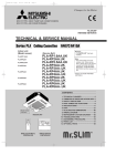
4-1-2. Operation pressure ranges
Permissible operation range
Normal operation range
4.5
Discharge pressure (MPa)
4
Overload operation
3.5
3
Standard operation
2.5
2
1.5
1
0.5
0
0
0.2
0.4
0.6
0.8
Suction pressure (MPa)
21
1
1.2
OCT04B-1.qxp
05.11.29 11:23 AM
Page 22
4-2. REFRIGERANT SYSTEM DIAGRAM
PLA-RP1.6AA
PLA-RP2AA
PLA-RP2.5AA
PLA-RP1.6AA.UK PLA-RP2AA.UK
PLA-RP2.5AA.UK
PLA-RP3AA
PLA-RP4AA
PLA-RP5AA
PLA-RP3AA.UK
PLA-RP4AA.UK
PLA-RP5AA.UK
PLA-RP3AA1
PLA-RP4AA1
PLA-RP5AA1
PLA-RP3AA1.UK
PLA-RP4AA1.UK
PLA-RP5AA1.UK
PKA-RP1.6GAL
PKA-RP2GAL
PKA-RP2.5FAL
PKA-RP3FAL
PKA-RP4FAL
PCA-RP2GA
PCA-RP2.5GA
PCA-RP3GA
PCA-RP4GA
PCA-RP5GA
PEA-RP3EA.TH-A PEA-RP4EA.TH-A PEA-RP5EA.TH-A
PEAD-RP1.6EA.UK PEAD-RP2EA.UK PEAD-RP2.5EA.UK
PEAD-RP3EA.UK PEAD-RP4EA.UK PEAD-RP5EA.UK
PEAD-RP3EA1.UK PEAD-RP4EA1.UK PEAD-RP5EA1.UK
PEAD-RP2.5GA.UK PEAD-RP3GA.UK PEAD-RP4GA.UK
PLA-RP6AA
PLA-RP6AA.UK
PLA-RP6AA1
PLA-RP6AA1.UK
PCA-RP6GA
PEA-RP6EA.TH-A
PEAD-RP6EA.UK
PEAD-RP6EA1.UK
Strainer
#50
Heat exchanger
Refrigerant GAS pipe connection
(Flare)
Condenser/evaporator
temperature thermistor
(TH5)
Refrigerant flow in cooling
Refrigerant flow in heating
Refrigerant LIQUID pipe connection
(Flare)
Pipe temperature
thermistor/liquid
(TH2)
Room temperature
thermistor (TH1)
Distributor
with strainer
#50
Strainer
#50
22
OCT04B-1.qxp
05.11.29 11:23 AM
Page 23
PUHZ-RP1.6VHA
PUHZ-RP2VHA
Heat exchanger
Stop valve
(with service port)
Refrigerant GAS pipe
connection(1/2F)
Thermistor TH6
(Outdoor 2-phase pipe)
Service port
Solenoid valve
(Four-way valve)
Thermistor TH7
(Outdoor)
Strainer
#50
Thermistor TH3
(Outdoor pipe)
Muffler
Distributor
High pressure
switch 63H
Thermistor TH4
(Discharge)
Muffler
Linear
expansion valve B
Compressor
Power
receiver
Linear expansion valve A
Stop valve
Refrigerant LIQUID pipe
connection(1/4F)
Strainer
#100
Strainer
#100
PUHZ-RP2.5VHA PUHZ-RP2.5VHA1
PUHZ-RP3VHA
PUHZ-RP3VHA1
PUHZ-RP3VHA-A PUHZ-RP3VHA1-A
Ball valve
Refrigerant GAS pipe
connection(5/8F)
Strainer
#50
Heat exchanger
Thermistor TH6
(Outdoor 2-phase pipe)
4-way valve
Oil separator
Bypass valve
Service port
(Low pressure)
Service port
(High pressure)
Capillary tube
O.D.4.0OI.D.2.4OL500
Strainer
#100
Thermistor TH4
(Discharge)
Strainer
#100
Stop valve
(with service port)
Strainer
#100
Power
receiver
Linear
expansion
valve B
Thermistor TH3
(Outdoor pipe)
Distributor
High pressure
switch 63H
Capillary tube
O.D.2.5OI.D.0.6OL1000
Refrigerant LIQUID pipe
connection(3/8F)
Thermistor TH7
(Outdoor)
Muffler Compressor
Linear expansion valve A
Strainer
#100
23
OCT04B-1.qxp
05.11.29 11:23 AM
PUHZ-RP4VHA
PUHZ-RP5VHA
PUHZ-RP6VHA
Refrigerant GAS pipe
connection(5/8F)
Page 24
PUHZ-RP4VHA-A
PUHZ-RP5VHA-A
PUHZ-RP6VHA-A
Ball valve Strainer
#50
Heat exchanger
Thermistor TH6
(Outdoor 2-phase pipe)
Solenoid valve
(Four-way valve)
Thermistor TH3
(Outdoor pipe)
Service port
(High pressure)
Muffler
Service port
(Low pressure)
Distributor
Low pressure
switch 63L
Strainer
#100
High pressure
switch 63H
Stop valve
(with service port)
Refrigerant LIQUID pipe
connection(3/8F)
Strainer
#100
Power
receiver
Compressor
Linear expansion valve A
Restrictor
valve
Strainer
#100
Strainer
#100
Strainer
#100
Solenoid valve
(Bypass valve)
Replace filter
PUHZ-RP4VHA1
PUHZ-RP5VHA1
PUHZ-RP6VHA1
Refrigerant GAS pipe
connection(5/8F)
Capillary tube
(O.D.4.0OI.D.3.0OL200)O2pcs
Thermistor TH4
(Discharge)
Strainer
#100
Linear
expansion valve B
PUHZ-RP4VHA1-A
PUHZ-RP5VHA1-A
PUHZ-RP6VHA1-A
Ball valve Strainer
#50
PUHZ-RP4YHA
PUHZ-RP5YHA
PUHZ-RP6YHA
Heat exchanger
Low pressure
switch 63L
Strainer
#100
Distributor
High pressure
switch 63H
Thermistor TH4
(Discharge)
Strainer
#100
Stop valve
(with service port)
Strainer
#100
Thermistor TH3
(Outdoor pipe)
Muffler
Service port
(Low pressure)
Linear
expansion valve B
Thermistor TH7
(Outdoor)
Thermistor TH6
(Outdoor 2-phase pipe)
Solenoid valve
(Four-way valve)
Service port
(High pressure)
Refrigerant LIQUID pipe
connection(3/8F)
Thermistor TH7
(Outdoor)
Power
receiver
Strainer
#100
Compressor
Linear expansion valve A
Restrictor
valve
Strainer
#100
Strainer
#100
Replace filter
Solenoid valve
(Bypass valve)
24
OCT04B-1.qxp
05.11.29 11:23 AM
Page 25
PUHZ-RP8YHA
PUHZ-RP10YHA
PUHZ-RP8YHA-A
PUHZ-RP10YHA-A
Refrigerant flow in cooling
Refrigerant flow in heating
High pressure switch 63H
Charge plug
(High pressure)
4-way valve
Stop valve
(with service port)
Refrigerant GAS pipe
connection
(RP8:1, RP10:1-1/8)
Strainer
#50
Strainer
#100
Capillary tube2
Replace
Bypass valve
filter
Oil
separator
Heat exchanger
Thermistor TH7
(Outdoor)
Strainer
#100
Charge plug
(Low pressure)
Accumulator
Thermistor TH6
(Outdoor 2-phase pipe)
Strainer
#100
Thermistor TH3
(Outdoor pipe)
Capillary tube1
Thermistor TH4
(Discharge)
Oil-back hole
Strainer#40
Low pressure switch 63L
Refrigerant LIQUID pipe
Stop valve
connection
(with service port)
(RP8:3/8F, RP10:1/2F)
Strainer
#50
Compressor
Linear expansion valve
Strainer
#100
Strainer
#100
25
Thermistor TH32
(Outdoor pipe)
OCT04B-1.qxp
05.11.29 11:23 AM
Page 26
4-3. APPLICABLE EXTENSION PIPE FOR EACH MODEL
PUHZ-RP•VHA(-A), PUHZ-RP4~6YHA
The height difference between indoor and outdoor unit should be kept within 30 m for all models.
4-3-1. 1:1 system
(a) Maximum pipe length
<Table 1> Pipe length for 1:1 system
Liquid OD
[6.35
pipe
Thickt0.8
(mm) ness
Gas OD
[12.7
[9.52
pipe
t0.8
t0.8
(mm) Thickness
30m
10m
RP1.6
RP2
RP2.5
RP3
RP4
RP5
RP6
[9.52
[12.7
t0.8
50m
50m
10m
10m
t0.8
[15.88
[12.7
[15.88
[19.05
[15.88
[19.05
t1.0
t0.8
t1.0
t1.0
t1.0
t1.0
30m
30m
10m
10m
30m (*1)
30m (*1)
50m
50m
75m (*2)
75m (*2)
75m (*2)
30m
30m
30m
30m
50m (*1)
50m (*1)
50m (*1)
30m
30m
50m
50m
50m
50m (*1)
50m (*1)
50m (*1)
*1: Set DIP SW8-1 on outdoor unit controller board to ON.
*2: The maximum length is 50 m in case of using existing pipes.
[Marks in the table above]
: Standard piping
: It can be used, however, additional refrigerant charge is required when the pipe length exceeds 20m.
: It cannot be used.
: It can be used.
: It can be used, however, the capacity is lowered.
Refer to (c) Capacity correction.
Refer to <table 4>.
(b) Adjusting the amount of refrigerant
• Additional refrigerant charge is not necessary for the pipe length up to 30 m. When the pipe length exceeds 30 m or service
(refrigerant replacement) is performed, charge proper amount of refrigerant for each pipe length referring to table below.
Use refrigerant R410A. Use charge hose exclusive for R410A.
• When charging additional refrigerant, charge the refrigerant from low-pressure side of the port valve using a safety charger.
• Make sure that air purge for this unit at refrigerant replacement is performed from both high-pressure check valve and service port. If air purge is performed only from one of them, air in not purged enough.
• When replacing refrigerant, charge the refrigerant from service port. When charged refrigerant is less than specified amount,
charge the refrigerant again from low pressure side of the port valve using a safety charger.
• Tighten the service port cap (nut) of stop valve firmly. The tightening torque is 12 to 16 N·m. (to prevent slow-leak)
• Check additional refrigerant charging amount referring to table 4 when liquid pipe is one size larger than standard diameter,
and table 2 when the pipe is standard diameter.
<Table 2> Additional refrigerant charging amount for pipe of standard diameter
Additional refrigerant charging amount for pipe
Permitted
Height
Number of
length exceeding 30 m (kg)
Outdoor unit
pipe length
difference
bends
—
—
—
—
75m
50m 51
60m 61
31
40m 41
50m or less
0.2kg
0.4kg
—
—
50m or less
PUHZ-RP2.5, 3VHA, 2.5, 3VHA1
PUHZ-RP4-6VHA, RP4-6VHA1, RP4-6YHA 75m or less
0.6Kg
1.2Kg
—
—
0.6kg
1.2kg
1.8kg
2.4kg
PUHZ-RP1.6, 2VHA
15
30m or
above
<Table 3>
Recharge refrigerant amount or additional amount in parentheses
Permitted
pipe length 10m or below 11 — 20m 21 — 30m 31 — 40m 41 — 50m 51 — 60m 61 — 75m
Outdoor unit
PUHZ-RP1.6, 2VHA
50m or less
2.1
2.3
2.5
PUHZ-RP2.5, 3VHA
PUHZ-RP2.5, 3VHA1
50m or less
3.1
3.3
3.5
PUHZ-RP4-6VHA
75m or less
5.1
5.3
5.5
PUHZ-RP4-6VHA1
PUHZ-RP4-6YHA
75m or less
4.6
4.8
5.0
2.7
2.9
—
—
(0.2)
(0.4)
—
—
4.1
4.7
—
—
(1.2)
—
—
(0.6)
6.1
6.7
7.3
7.9
(0.6)
(1.2)
(1.8)
(2.4)
5.6
6.2
6.8
7.4
(0.6)
(1.2)
(1.8)
(2.4)
<Table 4> Required additional charge when the pipe size is larger than the standard diameter
Liquid pipe dia Chargeless Max. pipe length Refrigerant amount to be added
RP1.6, 2
[9.52
20m
30m
60 g per 1 m longer than 20 m
RP2.5, 3
[12.7
20m
30m
100 g per 1 m longer than 20 m
RP4-6
[12.7
20m
50m
100 g per 1 m longer than 20 m
26
OCT04B-1.qxp
05.11.29 11:23 AM
Page 27
(c) Capacity correction
Cooling and heating capacity is lowered according to pipe length. Capacity can be obtained by referring to the capacity
curves below. When the diameter of gas pipe is one size smaller than standard diameter, cooling capacity is lowered comparing to the standard diameter. The lowered capacity can be obtained by referring to capacity curves for gas pipe which is
one size smaller than standard size.
Corrected pipe length (m) = actual pipe length (m) + number of bends x 0.3 (m)
1 Capacity curves for PUHZ-RP • HA model <Standard size>
100
Heating
Heating RP1.6, 2, 2.5,
3, 4, 5 and 6 models
Cooling RP1.6, 2.5 models (Up to 55m for RP1.6,
2, 2.5, 3 model)
Cooling RP3 model
95
Capacity ratio [%]
Cooling
90
85
Cooling RP2, 4 models
(Up to 55m for RP2
model)
Cooling RP5 model
80
75
Cooling RP6 model
Note: The permitted pipe length is up to 55m for RP1.6, 2, 2.5, 3 model.
70
5
10 15 20 25 30 35 40 45 50 55 60 65 70 75 80
Corrected pipe length
2 Capacity curve for PUHZ-RP1.6, 2 models
<When gas pipe is one size smaller than standard size>
100
Heating RP1.6, RP2
Capacity ratio [%]
95
90
Cooling RP2
85
Cooling RP1.6
80
5
10
15
20
25
30
35
Corrected pipe length
27
40
45
50
55
OCT04B-1.qxp
05.11.29 11:23 AM
Page 28
3 Capacity curve for PUHZ-RP2.5, 3 models
<When gas pipe is one size smaller than standard size>
100
Heating RP2.5, RP3
Capacity ratio [%]
95
90
Cooling RP2.5
85
80
Cooling RP3
5
10
15
20
25
30
35
Corrected pipe length
40
45
50
4 When gas pipe is one size larger than standard size for PUHZ-RP4, 5 and 6.
1 Capacity can be obtained by referring to capacity curves of standard size.
28
55
OCT04B-1.qxp
05.11.29 11:23 AM
Page 29
4-3-2. Synchronized twin and triple
(a) Pipe length
Please note that refrigerant piping length, bend number and height difference of indoor units are specified for each unit
combination.
Note: Be sure to use our Multi-distributor for distributing pipe to use existing piping.
<Table 5>
Permitted total piping
length A + B + C
Synchronized twin
Outdoor
unit
PUHZ-RP3VHA
PUHZ-RP3VHA-A
PUHZ-RP4-6VHA(-A)
PUHZ-RP4-6YHA
Chargeless piping
length A + B + C
Indoor unit’s height
difference [B and C]
Bend number
w2
8 m or less
15 at most
50 m or less
30 m or less
75 m or less
<Table 6>
Permitted total piping
length A + B + C + D
Synchronized twin
Indoor unit’s height difference Bend number
Charge-less piping
length A + B + C + D [B and C] [C and D] [B and D]
w2
Outdoor
unit
PUHZ-RP6VHA(-A)
70 m or less
30 m or less
15 at most
8 m or less
PUHZ-RP6YHA
Note 1: If total piping length exceeds charge-less piping length of 30 m, charge additional refrigerant according to the table 7.
<Table 7>
A + B + C (+D)
Additional refrigerant to be charged (kg)
30 m or less 31 - 40 m 41 - 50 m 51 - 60 m 61 - 75 m
Outdoor unit
PUHZ-RP3VHA
PUHZ-RP3VHA-A
PUHZ-RP4-6VHA(-A)
PUHZ-RP4-6YHA
Not required
0.6
w Charge additional
refrigerant from
the check valve
connected to the
pipe of low-pressure
side in indoor unit.
1.2
1.8
2.4
Note 2: Bends number (w 2) should be within 8 for each combination, A + B, A +C and A + D, and 15 in all.
Note 3: Height difference between indoor and outdoor unit is referred to no matter which unit is located higher or lower.
<Table 8> Pipe length for twin of RP 3 - 6 (Piping length: A + B + C)
RP3 Twin (RP1.6✕2)
RP4 Twin (RP2✕2)
RP5 Twin (RP2.5✕2)
RP6 Twin (RP3✕2)
Main pipe diameter [A]
Liquid [6.35 Liquid [9.52 Liquid [9.52 Liquid [12.7 Liquid [9.52 Liquid [12.7 Liquid [9.52 Liquid [12.7
Gas [12.7 Gas [15.88 Gas [15.88 Gas [19.05 Gas [15.88 Gas [19.05 Gas [15.88 Gas [19.05
Branch pipe Liquid [6.35
Gas [12.7
diameter
Liquid [9.52
[B and C]
Gas [15.88
Liquid [12.7
Gas [19.05
✕
50 m
✕
50 m
50 m
✕
✕
✕
75 m(✽2)
50 m(✽1)
50 m(✽1)
✕
✕
75 m(✽2)
✕
✕
50 m(✽1)
✕
✕
75 m(✽2)
✕
✕
50 m(✽1)
✕
<Table 9> Pipe length for triple of RP6 (Piping length: A + B + C + D)
Main pipe diameter [A]
✽1 ··· Set DIP SW8-1 on outdoor unit control circuit board to ON.
Liquid [9.52 Liquid [12.7
✽2 ··· When using existing piping, pipe length should be 50 m at most.
Gas [15.88 Gas [19.05
✽3 ··· Height difference between indoor and outdoor unit should be
kept within 30 m in every case.
Branch pipe Liquid [6.35
75 m(✽2)
50 m(✽1)
Gas [12.7
diameter
[Marks in table]
Liquid [9.52
··· Normal piping
50 m
50 m(✽1)
[B,C and D] Gas [15.88
··· It can be used with some changes of piping length and the
Liquid [12.7
Gas [19.05
✕
✕
amount of refrigerant to be charged.
✕ ··· It cannot be used.
29
OCT04B-1.qxp
05.11.29 11:23 AM
Page 30
Synchronized twin
Branch
pipe B
Indoor
unit
Branch
pipe C
Indoor
unit
30 m or less
1 m or less
30 m or less
1 m or less
Indoor
unit
Synchronized triple
Optional
distributing pipe
Multi-distributor
Main
pipe A
Branch
pipe B
Branch
pipe C
Branch
pipe D
Indoor
unit
Indoor
unit
Optional
distributing pipe
Multi-distributor
Outdoor
unit
Main
pipe A
Outdoor
unit
1. Keep Stop valve in outdoor unit fully closed (as it is shipped), and after completing refrigerant piping connection, conduct air
purge from service port of stop valve at outdoor unit.
2. After air purging, make the valve rod of stop valve at outdoor unit fully open.
Now refrigerating cycle is complete between indoor and outdoor unit.
Handle stop valve following the indication on outdoor unit.
Caution:
• Be sure to apply refrigerating oil to flare sheet face. Never apply it to screws. (As it causes flare nut loosening.)
• Use double spanner for piping connection.
• Be sure to check gas leak by using leak detector or soapy water.
• Use attached parts for refrigerant piping to provide correct insulation to the connection of indoor unit side in accordance with
attached explanation sheet.
• Be sure to provide an oxidized brazing.
(b) Adjusting the amount of refrigerant
(i) In case of RP 3 twin
Check the additional refrigerant to be charged referring to table 2 when using pipe of size referred in table 8.
(ii) In case of RP4 - 6 twin or RP6 triple
When using liquid pipe one size larger than standard diameter for main pipe A, calculate the amount of additional
refrigerant referring to 2 below.
1 When using piping of standard diameter or gas pipe one size larger than standard diameter for main pipe A.
Check the additional refrigerant to be charged referring to table 2 like 1:1 system.
2 When using liquid pipe one size larger than standard diameter for main pipe A.
[In case of RP4-6 using liquid pipe of [12.7]
• When total length of extension pipe (main pipe and branch pipe) is less than 20 m.
No adjustment is required for refrigerant. (Chargeless)
• When total length of extension pipe (main pipe and branch pipe) is more than 20 m.
Calculate the amount of additional refrigerant, referred to as W (g) in the following, using the equation below and add
proper amount of refrigerant. If W is less than or equal to 0, no additional charge is required. (Chargeless)
[Additional refrigerant]
W (g) = {100(g) ✕ L1} + {60(g) ✕ L2} + {30(g) ✕ L3} - 2000(g)
Note: Put “0” in L1-3 if it is not used.
L1: Liquid pipe length of [12.7 (m)
L2: Liquid pipe length of [9.52 (m)
L3: Liquid pipe length of [6.35 (m)
(c) Capacity correction
Apply pipe length between indoor and outdoor unit which is the longest of all for the calculation of capacity lowering according
to each pipe length.
30
OCT04B-2.qxp
05.11.29 11:27 AM
Page 31
4-4. APPLICABLE EXTENSION PIPE FOR EACH MODEL PUHZ-RP8, 10YHA(-A)
4-4-1. 1:1 system
(1) Pipe length
<Table 1> Maximum pipe length (RP8·RP10)
Liquid
pipe
(mm)
gas
pipe
(mm)
OD
Thickness
OD
Thickness
[9.52
[12.7
[15.88
t0.8
t0.8
t1.0
[19.05
[22.2
[25.4
[28.58
[19.05
[22.2
[25.4
[28.58
[22.2
[25.4
[28.58
[31.75
t1.0
t1.0
t1.0
t1.0
t1.0
t1.0
t1.0
t1.0
t1.0
t1.0
t1.0
t1.0
RP8
20m
[20m]
50m
[30m]
Normal piping
70mw1
[30m]
70m
[30m]
20m
[20m]
50m
[30m]
70m
[30m]
70m
[30m]
50m
[20m]
50m
[20m]
50m
[20m]
w2 SW
50m
[20m]
RP10
20m
[20m]
50m
[30m]
70m
[30m]
70m
[30m]
20m
[20m]
50m
[30m]
70m
[30m]
Normal piping
70mw1
[30m]
50m
[20m]
50m
[20m]
50m
[20m]
w2
50m
[20m]
SW
SW
SW
Note : The maximum pipe length is 80m in case of new piping.
w1 Be sure to use hard (tempered) one for pipe over [22.2.(Do not use soft (annealed) one.)
w2 When using [31.75 pipe, the outdoor temperature range (dry-bulb temperature) for heating operation is -11 to +21:.
<Marks in the table above>
SW : When the outdoor unit is located lower than
the indoor unit, set DIP SW8-1 on the outdoor
unit controller board to ON.
: It can be used.
: Cooling capacity is lowered.➝ Refer to <Table6>
: Additional refrigerant charge is required when
the pipe length exceeds 20m.➝ Refer to <Table7>
SW
70m
[30m]
The maximum pipe length
Charge-less pipe length
(2) Adjusting the amount of refrigerant
Check additional refrigerant charging amount referring to table 7 when the liquid pipe diameter is larger than
the standard size, and table 2 when the pipe of the standard diameter is used.
<Table 2>
permitted
pipe length
Outdoor unit
RP8
RP10
At time of shipping
(kg)
10.5
80m or less
Amount of additional refrigerant charge (kg)
30 m and less
No additional
charge necessary
10.5
31-40 m and less 41-50 m and less 51-60 m and less 61-70 m and less 71-80 m and less
The additional charge
0.9 kg
1.8 kg
2.7 kg
3.6 kg
1.2 kg
2.4 kg
3.6 kg
4.8 kg
amount is obtained by
the following formula.
Calculate the additional charge amount based on the following procedure.
If the calculation results in an amount that is smaller than the "Additional charge amount for 70m," perform the additional charge using the amount shown
in "Additional charge amount for 70m."
Amount of additional
charge [kg]
=
Main piping:
Liquid line size
[12.7 over all length [m]
o 0.12 [kg/m]
Additional charge amount RP8
for 70 m
RP10
+
Main piping:
Liquid line size
[9.52 overall length [m]
o 0.09 [kg/m]
3.6 kg
4.8 kg
31
+
Branch piping: Liquid
line size
[9.52 overall length [m]
o 0.06 [kg/m]
+
Branch piping: Liquid
line size
[6.35 overall length [m]
o 0.02 [kg/m]
–
3.6 (kg)
OCT04B-2.qxp
05.11.29 11:27 AM
Page 32
(3) Capacity correction
Cooling and heating capacity is lowered according to the piping length. Capacity can be obtained by referring
to the following capacity curves.
When the diameter of the gas pipe is smaller than the standard size, cooling capacity is lowered comparing to
the operation using the standard diameter pipe.
The lowered capacity can be obtained by referring to the capacity curves for gas pipe which is one or two size
smaller than standard size.
Corrected pipe length (m) = actual pipe length (m) + number of bends o 0.3 (m)
1. Capacity curves 1 <Standard size>
100
95
Capacity ratio [%]
Heating RP8·10
90
85
RP8·10
80
75
70
5
10
15
20
25
30
35
40
45
50
55
60
65
70
75
80
85
Corrected pipe length (m)
2. Capacity curves 2 <When the gas pipe's diameter is one-size-smaller than the standard
100
Heating RP8([22.2), RP10([25.4)
Capacity ratio [%]
95
Cooling RP10([25.4)
90
85
80
Cooling RP8([22.2)
75
70
5
10
15
20
25
30
35
40
45
50
55
Corrected pipe length [m]
3. Capacity curves 3 <When the gas pipe's diameter is two-size-smaller than the standard
100
Cpacity ratio [%]
95
Heating RP8([19.05), RP10([22.2)
90
85
Cooling RP10([22.2)
80
Cooling RP8([19.05)
75
70
5
10
15
20
Corrected pipe length [m]
32
25
OCT04B-2.qxp
05.11.29 11:27 AM
Page 33
4-4-2. Synchronized twin, triple and quadruple system
(1) Synchronized twin
Maximum pipe length (Main pipe[A]+Branch pipe diameter [ B and C ])
Main pipe
(mm)[A]
RP8 twin (RP4✕2)
RP10 twin (RP5✕2)
[9.52
[12.7
[15.88
[9.52
[12.7
[15.88
[19.05 [22.2 [25.4 [28.58 [19.05 [22.2 [25.4 [28.58 [22.2 [25.4 [28.58 [31.75 [19.05 [22.2 [25.4 [28.58 [19.05 [22.2 [25.4 [28.58 [22.2 [25.4 [28.58 [31.75
Liquid pipe
Gas pipe
Liquid pipe
[6.35
Gas pipe
[12.7
Normal
Normal
Liquid pipe
Branch
pipe Gas pipe
[mm]
Liquid pipe
[B, C]
Gas pipe
[9.52
sw w2 sw
w2
sw
sw
piping
piping
20m 50m 70mw1 70m 20m 50m 70m 70m 50m 50m 50m 50m 20m 50m 70m 70m 20m 50m 70m 70mw1 50m 50m 50m 50m
[15.88 [20m] [30m] [30m] [30m] [20m] [30m] [30m] [30m] [20m] [20m] [20m] [20m] [20m] [30m] [30m] [30m] [20m] [30m] [30m] [30m] [20m] [20m] [20m] [20m]
Liquid pipe
[12.7
sw
sw
w2
sw w2 sw
20m 50m 70m 70m 20m 50m 70m 70m 50m 50m 50m 50m 20m 50m 70m 70m 20m 50m 70m 70m 50m 50m 50m 50m
[19.05 [20m] [30m] [30m] [30m] [20m] [30m] [30m] [30m] [20m] [20m] [20m] [20m] [20m] [30m] [30m] [30m] [20m] [30m] [30m] [30m] [20m] [20m] [20m] [20m]
Gas pipe
[9.52
w2
sw
sw
sw w2 sw
20m 50m 70m 70m 20m 50m 70m 70m 50m 50m 50m 50m 20m 50m 70m 70m 20m 50m 70m 70m 50m 50m 50m 50m
[19.05 [20m] [30m] [30m] [30m] [20m] [30m] [30m] [30m] [20m] [20m] [20m] [20m] [20m] [30m] [30m] [30m] [20m] [30m] [30m] [30m] [20m] [20m] [20m] [20m]
w1 The maximum pipe length is 80m in case of new pipping.
w2 When using [31.75 pipe, the outdoor temperature range (dry-bulb temperature) for heating operation is -11 to +21:.
(2) Synchronized triple
Maximum pipe length (Main pipe [A] + Branch pipe [ B, C and D ])
Main pipe
(mm)[A]
RP8 triple (RP2.5✕3)
RP10 triple (RP3✕3)
[9.52
[12.7
[15.88
[9.52
[12.7
[15.88
[19.05 [22.2 [25.4 [28.58 [19.05 [22.2 [25.4 [28.58 [22.2 [25.4 [28.58 [31.75 [19.05 [22.2 [25.4 [28.58 [19.05 [22.2 [25.4 [28.58 [22.2 [25.4 [28.58 [31.75
Liquid pipe
Gas pipe
Liquid pipe
[6.35
Gas pipe
[12.7
Liquid pipe
Branch
pipe Gas pipe
[mm]
Liquid pipe
[B, C, D]
Gas pipe
Liquid pipe
Gas pipe
Normal
Normal
sw w2 sw
w2
sw
sw
piping
piping
20m 50m 70mw1 70m 20m 50m 70m 70m 50m 50m 50m 50m 20m 50m 70m 70m 20m 50m 70m 70mw1 50m 50m 50m 50m
[15.88 [20m] [30m] [30m] [30m] [20m] [30m] [30m] [30m] [20m] [20m] [20m] [20m] [20m] [30m] [30m] [30m] [20m] [30m] [30m] [30m] [20m] [20m] [20m] [20m]
[9.52
[9.52
w2
sw
sw
sw w2 sw
20m 50m 70m 70m 20m 50m 70m 70m 50m 50m 50m 50m 20m 50m 70m 70m 20m 50m 70m 70m 50m 50m 50m 50m
[19.05 [20m] [30m] [30m] [30m] [20m] [30m] [30m] [30m] [20m] [20m] [20m] [20m] [20m] [30m] [30m] [30m] [20m] [30m] [30m] [30m] [20m] [20m] [20m] [20m]
[12.7
sw
sw
w2
sw w2 sw
20m 50m 70m 70m 20m 50m 70m 70m 50m 50m 50m 50m 20m 50m 70m 70m 20m 50m 70m 70m 50m 50m 50m 50m
[19.05 [20m] [30m] [30m] [30m] [20m] [30m] [30m] [30m] [20m] [20m] [20m] [20m] [20m] [30m] [30m] [30m] [20m] [30m] [30m] [30m] [20m] [20m] [20m] [20m]
w1 The maximum pipe length is 80m in case of new pipping.
w2 When using [31.75 pipe, the outdoor temperature range (dry-bulb temperature) for heating operation is -11 to +21:.
(3) Synchronized quadruple
Maximum pipe length (Main pipe[A]+Branch pipe [ B, C, D and E ])
Main pipe
(mm)[A]
RP8 quadruple (RP2✕4)
RP10 quadruple (RP2.5✕4)
[9.52
[12.7
[15.88
[9.52
[12.7
[15.88
[19.05 [22.2 [25.4 [28.58 [19.05 [22.2 [25.4 [28.58 [22.2 [25.4 [28.58 [31.75 [19.05 [22.2 [25.4 [28.58 [19.05 [22.2 [25.4 [28.58 [22.2 [25.4 [28.58 [31.75
Liquid pipe
Gas pipe
Liquid pipe
Gas pipe
Liquid pipe
Branch
pipe Gas pipe
[mm]
Liquid pipe
[B, C, D, E]
Gas pipe
Liquid pipe
Gas pipe
Normal
sw w2 sw
sw
sw
piping
20m 50m 70mw1 70m 20m 50m 70m 70m 50m 50m 50m 50m
[12.7 [20m] [30m] [30m] [30m] [20m] [30m] [30m] [30m] [20m] [20m] [20m] [20m]
[6.35
Normal
w2
sw
sw
sw w2 sw
piping
20m 50m 70m 70m 20m 50m 70m 70m 50m 50m 50m 50m 20m 50m 70m 70m 20m 50m 70m 70mw1 50m 50m 50m 50m
[15.88 [20m] [30m] [30m] [30m] [20m] [30m] [30m] [30m] [20m] [20m] [20m] [20m] [20m] [30m] [30m] [30m] [20m] [30m] [30m] [30m] [20m] [20m] [20m] [20m]
[9.52
[9.52
sw
sw
w2
sw w2 sw
20m 50m 70m 70m 20m 50m 70m 70m 50m 50m 50m 50m 20m 50m 70m 70m 20m 50m 70m 70m 50m 50m 50m 50m
[19.05 [20m] [30m] [30m] [30m] [20m] [30m] [30m] [30m] [20m] [20m] [20m] [20m] [20m] [30m] [30m] [30m] [20m] [30m] [30m] [30m] [20m] [20m] [20m] [20m]
w2
20m 50m 70m 70m 20m 50m 70m 70m 50m 50m 50m 50m
[20m] [30m] [30m] [30m] [20m] [30m] [30m] [30m] [20m] [20m] [20m] [20m]
[12.7
[19.05
w1 The maximum pipe length is 80m in case of new pipping.
w2 When using [31.75 pipe, the outdoor temperature range (dry-bulb temperature) for heating operation is -11 to +21:.
<Marks in the table above>
SW : When the outdoor unit is located lower than
the indoor unit, set DIP SW8-1 on the outdoor
unit controller board to ON.
SW
70m
[30m]
: It can be used.
: Cooling capacity is lowered.➝ Refer to <Table6>
: Additional refrigerant charge is required when
the pipe length exceeds 20m.➝ Refer to <Table7>
The maximum pipe length
Charge-less pipe length
33
OCT04B-2.qxp
05.11.29 11:27 AM
Page 34
Pipe diameter and thickness
OD
(mm) [6.35
Thickness
0.8
(mm)
[9.52
[12.7
0.8
0.8
[15.88 [19.05
1.0
[22.2
1.0
1.0
[25.4 [28.58
1.0
[31.75
1.0
1.1
Be sure to use hard (tempered) one for pipe over [22.2.(Do not use soft (annealed) one.)
4
B
4
D
1
2
3
4
5
1
4
E
1
Indoor unit
Outdoor unit
Main piping
Branch piping
Multi disttibution
pipe (option)
1 Height difference (Indoor unitOutdoor unit) Max. 40 m
2 Height difference (Indoor unitIndoor unit) Max. 1 m
3 Distance between indoor and indoor units
pipe length.
1
1
4
C
2
1
B—C B—D B—E
C—D C—E D—E
5
3
A
4 Number of pipe bends
Within 15
points8 points between main pipe A and
each branch pipe (B, C, D, E).
2
<Table 6> Lowered cooling capacity by the smaller gas pipe diameter
RP8 Cooling capacity ratio
gas pipe [22.2
gas pipe [19.05
100%
100%
100~96%
100~91%
96~91%
91~81%
91~86%
86~83%
83~80%
Pipe length
5m and less
6~10m
11~20m
21~30m
31~40m
41~50m
RP10 Cooling capacity ratio
gas pipe [25.4
gas pipe [22.2
100%
100%
100~98%
100~95%
98~94%
95~88%
94~91%
91~88%
88~86%
<Table 7> Additional refrigerant amount when the liquid pipe of the larger diameter is used.
(Single /Simultaneous Twin / Simultaneous Triple / Simultaneous Quadruple)
Capacity
RP8, RP10
When the extension pipe length (main piping + branch piping) exceeds 20m
Additional refrigerant amount W(g)=(180oL1)+(120oL2) (90oL3)+(30oL4)-3000
L1 : [15.88 liquid pipe (m)
L3 : [9.52 liquid pipe (m)
L2 : [12.7 liquid pipe (m)
L4 : [6.35 liquid pipe (m)
If the calculation produces a negative number (i.e. a "minus" charge), additional charging is not necessary.
( W [ 0)
<Table 8>
Outdoor unit
Permissible total
piping length
A+B+C+D+E
A+B or A+C
or
A+D or A+E
Charge-less
piping length
A+B+C+D+E
RP8
PR10
80 m and less
80 m and less
30 m and less
Outdoor unit
B-C or B-D or
B-E or C-D or
C-E or D-E
Number of
pipe bends
RP8
RP10
8 m and less
<Table 9>
Within 15
34
OCT04B-2.qxp
05.11.29 11:27 AM
Page 35
<Table 10>
Outdoor unit
RP8
RP10
permitted
pipe length
80m or less
At time of shipping
(kg)
10.5
A+B+C+D
30 m and less
No additional
charge necessary
10.5
Amount of additional refrigerant charge (kg)
31-40 m and less 41-50 m and less 51-60 m and less 61-70 m and less 71-80 m and less
The additional charge
0.9 kg
1.8 kg
2.7 kg
3.6 kg
1.2 kg
2.4 kg
3.6 kg
4.8 kg
amount is obtained by
the following formula.
When length exceeds 70 m
When the total length of the piping exceeds 70 m, calculate the amount of additional charge based on the following requirements.
Note: If the calculation produces a negative number (i.e. a “minus” charge), of if calculation results in an amount that is less than the
“Additional charge amount for 70 m,”perform the additional charge using the amount shown in “Additional charge amount for 70 m.”
Amount of additional
charge
=
Main piping:
Liquid line size
[12.7 overall length
0.12
Additional charge amount RP8
for 70 m
RP10
+
Main piping:
Liquid line size
[9.52 overall length
0.09 (Gas line:[28.58)
+
Branch piping: Liquid
line size
[9.52 overall length
0.06 (Gas line: [15.88)
+
Branch piping: Liquid
line size
[6.35 overall length
0.02 (Gas line: [15.88)
–
3.6 (kg)
3.6 kg
4.8 kg
1. Perform refrigerant piping connections for the indoor / outdoor unit while the outdoor unit's stopvalve is completely
closed (factory setting), and then vacuumize the refrigerant lines through the service port of the outdoor unit.
2. Open the stop valves of the outdoor unit completely.
This will completely connects the refrigerant lines of the indoor and outdoor units.
Handling of the stop valve is shown on the outdoor unit.
Note :
· Apply refrigerating machine oil over the flare seat surface. Do not apply to the threaded portion.
(It will cause the flare nut to loosen.)
· Use two wrenches to tighten piping connection.
· Use leak detector or soapy water to check for gas leaks after connections are completed.
· For the insulation of the connection at the indoor side, make sure to use the attached insulation materials and
thoroughly follow the instruction shown in the manual.
· Always use a non-oxidizing brazing material when brazing the pipes.
Adjusting the amount of refrigerant
Check additional refrigerant charging amount referring to the procedure 2 below when the liquid pipe diameter of the main
piping A is larger than the standard size.
1 When the standard diameter pipe is used for the main piping A, calculate the additional refrigerant amount by
referring to <Table 2> as well as the 1:1 system.
2 When the liquid pipe diameter of the main piping A is one size larger than the standard size:
· When the extension pipe length (main piping + branch piping) does not exceeds 20m, adjustment of the
refrigerant is not necessary (charge-less).
· When the extension pipe length (main piping + branch piping) exceeds 20m, charge the amount of refrigerant
that is obtained by the formula shown in <Table 7>.
If the calculation produces a negative number (i.e. a "minus" charge), additional charging is not necessary.
Note: Apply 0 to L1 to L3 corresponding to the piping that are not used.
Correcting the capacity value
When calculating the lowered capacity by the extension pipe length, use the longest length between the indoor and the outdoor
units.
35
OCT04B-2.qxp
5
05.11.29 11:27 AM
Page 36
HOW TO CHECK THE PARTS
5-1. INDOOR UNIT
• Common parts
Parts name
Check points
Room temperature
thermistor
(TH1)
Disconnect the connector then measure the resistance using a tester.
(Surrounding temperature 10:~30:)
Pipe temperature
thermistor/ liguid (TH2)
Condenser/evaporator
temperature thermistor
(TH5)
Drain sensor
Normal
Abnormal
4.3k"~9.6k"
Open or short
(Refer to below for a detail.)
Measure the resistance between the terminals using a tester.
Measure the resistance after 3 minutes have passed since the power supply was intercepted.
(Surrounding temperature 0:~60:)
1
2
3
Normal
Abnormal
0.6k"~6.0k"
Open or short
(Refer to below for a detail.)
<Thermistor Characteristic graph>
< Thermistor for lower temperature >
Thermistor R0=15kΩ ± 3%
Fixed number of B=3480 ± 2%
Rt=15exp { 3480(
0:
10:
20:
25:
30:
40:
50
Room temperature thermistor(TH1)
Pipe temperature thermistor(TH2)
Condenser/evaporator temperature
thermistor(TH5)
1
273+t
40
Resistance (k")
Thermistor for
lower temperature
1 )}
273
15kΩ
9.6kΩ
6.3kΩ
5.2kΩ
4.3kΩ
3.0kΩ
30
20
10
0
10
Drain sensor
-20 -10 0 10 20 30 40 50
Temperature (:)
< Thermistor for drain sensor >
9
8
Thermistor R0=6.0kΩ ±5%
Fixed number of B=3390 ±2%
0:
10:
20:
25:
30:
40:
60:
Resistance (k")
Rt=6exp { 3390( 1
273+t
7
1 )}
273
6.0kΩ
3.9kΩ
2.6kΩ
2.2kΩ
1.8kΩ
1.3kΩ
0.6kΩ
6
5
4
3
2
1
0
-20
36
0
20 40 60
Temperature (:)
80
OCT04B-2.qxp
05.11.29 11:27 AM
PLA-RP1.6AA
PLA-RP1.6AA.UK
PLA-RP3AA
PLA-RP3AA1
PLA-RP3AA.UK
PLA-RP3AA1.UK
Page 37
PLA-RP2AA
PLA-RP2AA.UK
PLA-RP4AA
PLA-RP4AA1
PLA-RP4AA.UK
PLA-RP4AA1.UK
PLA-RP2.5AA
PLA-RP2.5AA.UK
PLA-RP5AA
PLA-RP5AA1
PLA-RP5AA.UK
PLA-RP5AA1.UK
Parts name
Check points
Vane motor
Measure the resistance between the terminals using a tester.
(Surrounding temperature20:)
Fan motor
Relay connector
1
Red
2 White
Abnormal
15k"
Open or short
Normal
Motor terminal PLA-RP1.6, 2, 2.5, 3AA
PLA-RP4, 5, 6AA
or
PLA-RP1.6, 2, 2.5, 3AA.UK PLA-RP4, 5, 6AA.UK
PLA-RP4, 5, 6AA1
Relay connector PLA-RP3AA1
2
PLA-RP3AA1.UK
3
Protector
OPEN :130:
CLOSE:80i20:
Drain pump
Normal
Measure the resistance between the terminals using a tester.
(Winding temperature 20:)
1
3 Black
Red-Black
87.2"
28.7"
White-Black
104.1"
41.6"
1
Normal
Abnormal
2
290"
Open or short
Red
PKA-RP1.6GAL
Parts name
Fan motor (MF)
Relay connector
Red
2
White
3
Black
1
2
3
Vane motor (MV)
Red
2
Pink
Red – Black
120.5"
White – Black
111.3"
Red – Orange
3 6 1
Parts name
Fan motor (MF)
Relay connector
1
2
Red
1
White
3 Black
2
3
Protector
OPEN : 130i 5:
CLOSE : 80i 20:
Vane motor (MV)
Open or short
PKA-RP3FAL
M
PKA-RP4FAL
Check points
Measure the resistance between the terminals using a tester.
(Winding temperature 20:)
Normal
Motor terminal
or
Abnormal
RP2.5
RP4
Relay connector
RP3
Red – Black
99.5"
62.6"
White – Black
103.9"
74.0"
Open or short
Measure the resistance between the terminals using a tester.
(Surrounding temperature 20:~30:)
4 Orange
Pink
186~214"
Red – Pink
PKA-RP2.5FAL
2
Abnormal
Brown – Yellow
Brown – Blue
Red
Normal
Connector
M
Yellow Brown Blue
5
Open or short
Measure the resistance between the terminals using a tester.
(Surrounding temperature 20:~30:)
4 Orange
5
PKA-RP2GAL
Check points
Measure the resistance between the terminals using a tester.
(Winding temperature 20:)
Normal
Motor terminal
or
Abnormal
RP1.6 , RP2
Relay connector
Protector
OPEN : 125i 5:
CLOSE : 79i 15:
Connector
Normal
Abnormal
RP2.5, RP3, RP4
Brown –Y ellow
Yellow Brown Blue
Brown – Blue
3 6 1
Red – Orange
Abnormal
PLA-RP4, 5, 6AA1.UK
Measure the resistance between the terminals using a tester.
(Winding temperature 20:)
Red
1
PLA-RP6AA
PLA-RP6AA1
PLA-RP6AA.UK
PLA-RP6AA1.UK
Open or short
186~214"
Red – Pink
37
Open or short
OCT04B-2.qxp
05.11.29 11:27 AM
PCA-RP2GA
PCA-RP4GA
Page 38
PCA-RP2.5GA
PCA-RP5GA
PCA-RP3GA
PCA-RP6GA
Parts name
Check points
Measure the resistance between the terminals using a tester.
(Winding temperature 20:)
Fan motor
Relay connector
1
Red
2 White
3 Black
1
Motor terminal
or
Relay connector
2
Normal
RP2
RP2.5, RP3
RP4
RP5, RP6
Red – Black
70.6"
45.0"
43.7"
20.4"
White – Black
69.6"
44.8"
55.3"
20.7"
3
Protector
OFF : 130i 5:
ON : 80i 20:
Vane motor
Red
2
Pink
M
Brown – Blue
3 6 1
Pink
Red – Orange
186~214"
140~160"
Normal
Connector
M
Abnormal
Open or short
Abnormal
RP4, RP5, RP6
Brown – Yellow
Brown – Blue
Red
Yellow
Blue
3
1
Open or short
140~160"
Red – Orange
Red – Pink
Drain-up
mechanism (Option)
Gray
RP2.5, RP3
Red – Pink
2 Orange
5
RP2
Brown – Yellow
Yellow Brown Blue
4
Normal
Connector
4 Orange
5
Measure the resistance between the terminals using a tester.
(Winding temperature 20:)
1
Normal
Abnormal
2
195"
Open or short
Gray
PEA-RP3EA.TH-A PEA-RP4EA.TH-A PEA-RP5EA.TH-A PEA-RP6EA.TH-A
Parts name
Fan motor (MF)
Protector
(PEA-RP3,4,5EA)
OPEN :135:
CLOSE:86i15:
(PEA-RP6EA)
OPEN :150:
CLOSE:96i15:
White
Orange
Red
Brown
Blue
Black
Abnormal
Check points
Measure the resistance between the terminals using a tester.
(Winding temperature 20:)
Motor terminal
or
Relay connector
Normal
Abnormal
PEARP3EA.TH-A RP4EA.TH-A RP5EA.TH-A RP6EA.TH-A
White – Black
28.6"
20.6"
15.3"
10.2"
Black – Blue
12.5"
8.1"
5.1"
5.2"
Blue – Brown
4.3"
3.2"
2.7"
3.1"
Brown – Red
23.6"
16.0"
14.5"
12.1"
38
Open or short
Open or short
OCT04B-2.qxp
05.11.29 11:27 AM
Page 39
PEAD-RP1.6EA.UK PEAD-RP2EA.UK
PEAD-RP3EA.UK
PEAD-RP4EA.UK
PEAD-RP3EA1.UK PEAD-RP4EA1.UK
Parts name
Check points
Fan motor (MF)
Measure the resistance between the terminals using a tester.
(Winding temperature 20:)
PEAD-RP3EA(1).UK
Motor terminal
or
Relay connector
Black
Blue
Gray – Black
Gray
Red
PEAD-RP2.5EA.UK
PEAD-RP5EA.UK
PEAD-RP6EA.UK
PEAD-RP5EA1.UK PEAD-RP6EA1.UK
White
Protector
OPEN :150:
CLOSE:96i15:
(White or Red open)
Black – Blue
(White or Red open)
Blue – Red
(White or Red open)
PEAD-RP4,5,6EA(1).UK
Blue
Motor terminal
or
Relay connector
Red
(White or Red open)
Black
Gray-Black
Normal
Abnormal
PEAD-RP1.6, 2, 2.5EA.UK
PEAD-RP3EA(1).UK
43.5"
Open or short
14.74"
57.5"
Normal
Abnormal
PEADRP4EA(1).UK
RP5EA(1).UK RP6EA(1).UK
24.76"
10.27"
4.78"
2.11"
18.99"
20.75"
36.63"
25.44"
White
Blue – Black
Gray
Protector
OPEN :135:
CLOSE:86i15:
Black – Red
(White or Red open)
Gray – Red
(White or Red open)
Open or short
PEAD-RP2.5GA
PEAD-RP3GA
PEAD-RP4GA
39
OCT04B-2.qxp
05.11.29 11:28 AM
Page 40
5-2. OUTDOOR UNIT
PUHZ-RP1.6HA
PUHZ-RP3VHA1(-A)
PUHZ-RP2VHA
PUHZ-RP4VHA(-A)
PUHZ-RP2.5VHA
PUHZ-RP4VHA1(-A)
PUHZ-RP2.5VHA1 PUHZ-RP5VHA(-A)
PUHZ-RP3VHA(-A) PUHZ-RP5VHA1(-A)
PUHZ-RP6VHA(-A)
PUHZ-RP6VHA1(-A)
PUHZ-RP4YHA
PUHZ-RP5YHA
PUHZ-RP6YHA
Check points
Parts name
Thermistor (TH3)
<Outdoor pipe>
Disconnect the connector then measure the resistance using a tester.
(Surrounding temperature 10:~30:)
Thermistor (TH4)
<Discharge>
Thermistor (TH6)
<Outdoor 2-phase pipe>
TH4
Thermistor (TH7)
<Outdoor>
TH6
Thermistor (TH8)
<Heat sink>
TH8
Normal
Abnormal
160k"~410k"
TH3
4.3k"~9.6k"
Open or short
TH7
39k"~105k"
Fan motor(MF1,MF2) Measure the resistance between the terminals using a tester. (Winding temperature 20:)
Normal
Red W
Relay connector
Abnormal
RP1.6V, 2V
RP2.5-6V
RP4-6Y
White
Red — Black
V
Black
Open or short
w
66.5±3.3"
15.1±0.5"
Black — White
U
Pin number of relay
connector is different
from that motor
connector
Solenoid valve coil
<Four-way valve>
(21S4)
White — Red
w Refer to the next page for how to check the contact
failure or how to measure the voltage at test point.
Measure the resistance between the terminals using a tester.
(Surrounding temperature 20:)
Normal
Abnormal
RP1.6-3V
RP4-6
2350±170"
1370±100"
Open or short
Motor for compressor Measure the resistance between the terminals using a tester.
(Winding temperature 20:)
U
(MC)
Normal
Abnormal
V
RP1.6V, 2V
RP2.5V, 3V
RP4-6V
RP4-6Y
W
0.300"~0.340"
0.865"~0.895"
0.266"
1.064"
Open or short
Linear expansion valve Disconnect the connector then measure the resistance using a tester.
(Winding temperature 20:)
( LEV(A),LEV(B) )
RP1.6-RP6VHA only
M
Normal
Red
1
2
Blue
3
Orange
4
Yellow 5
White
6
Abnormal
Brown
Red - White
Red - Orange
Brown - Yellow
Brown - Blue
Open or short
46±4"
Linear expansion valve Disconnect the connector then measure the resistance using a tester.
( LEV(A),LEV(B) )
(Winding temperature 20:)
RP4-RP6YHA only
M
Normal
White
1
2
Orange 3
Red
4
Yellow 5
Black
6
Abnormal
Gray
Solenoid valve coil
<Bypass valve>
(SV)
RP2.5-6 only
White - Black
White - Red
Gray - Yellow
Gray - Orange
46±3"
Measure the resistance between the terminals using a tester.
(Surrounding temperature 20:)
Normal
1197±10"
Abnormal
Open or short
40
Open or short
OCT04B-2.qxp
05.11.29 11:28 AM
Page 41
Check method of DC fan motor (fan motor / outdoor controller circuit board)
1 Notes
· High voltage is applied to the connecter (CNF1, 2) for the fan motor. Give attention to the service.
· Do not pull out the connector (CNF1, 2) for the motor with the power supply on.
(It causes trouble of the outdoor controller circuit board and fan motor.)
2 Self check
Symptom : The outdoor fan cannot turn around.
Wiring contact check
Contact of fan motor connector (CNF1, CNF2)
Is there no contact failure?
No
Wiring recovery
Yes
Power supply check
Measure the voltage in the outdoor controller circuit board.
TEST POINT 1 : VDC (between 1 (+) and 4 (-) of the fan connector): Vdc DC250-330V
TEST POINT 2 : VCC (between 5 (+) and 4 (-) of the fan connector): Vcc DC15V
TEST POINT 3 : VSP (between 6 (+) and 4 (-) of the fan connector): Vsp DC1 to 6.5V
The voltage of VSP is a value during the fan motor operation.
In the case that the fan motor off, the voltages is 0V.
[
]
Is the voltage normal?
No
Trouble of the outdoor controller circuit board
Replacement of the outdoor controller circuit board
Yes
Fan motor position sensor signal check
Measure the voltage at the TEST POINT 4 (VFG), between 7 (+) and 4 (-)
of the fan connector, while slowly turning the fan motor more than one revolution.
Dose the voltage repeat DC0V and DC15V?
Trouble of the fan motor
Replacement of the motor
No
Yes
Replacement of the outdoor controller circuit board
41
OCT04B-2.qxp
05.11.29 11:28 AM
PUHZ-RP8YHA
PUHZ-RP10YHA
Page 42
PUHZ-RP8YHA-A
PUHZ-RP10YHA-A
Check points
Parts name
Thermistor (TH3, TH32) Disconnect the connector then measure the resistance using a tester.
(Surrounding temperature 10:~30:)
<Outdoor pipe>
Normal
Thermistor (TH4)
<Discharge>
TH4
Thermistor (TH6)
<Outdoor 2-phase pipe>
Thermistor (TH7)
<Outdoor>
Abnormal
160k"~410k"
TH3, TH32
TH6
4.3k"~9.6k"
Open or short
TH7
Fan motor(MF1,MF2) Measure the resistance between the terminals using a tester.
(Winding temperature 20:)
Black W
White
Red
V
U
Pin number of relay
connector is different
from that motor
connector
Solenoid valve coil
<Four-way valve>
(21S4)
Relay connector
Normal
Abnormal
15.3±0.5"
Open or short
Red — Black
Black — White
White — Red
Measure the resistance between the terminals using a tester.
(Surrounding temperature 20:)
Normal
Abnormal
1370±100"
Open or short
Motor for compressor Measure the resistance between the terminals using a tester.
(Winding temperature 20:)
(MC)
U
V
Normal
Abnormal
0.72"
Open or short
W
Linear expansion valve Disconnect the connector then measure the resistance using a tester.
(Winding temperature 20:)
( LEV(A) )
Abnormal
Normal
M
Red
1
Brown 2
Blue 3
Orange 4
Yellow 5
White 6
Solenoid valve coil
<Bypass valve>
(SV)
Red - White Red - Orange Brown - Yellow Brown - Blue
Open or short
46±4"
Measure the resistance between the terminals using a tester.
(Surrounding temperature 20:)
Normal
1197±10"
Abnormal
Open or short
42
OCT04B-2.qxp
05.11.29 11:28 AM
Page 43
5-3. COMPRESSOR TECHNICAL DATA
(at 20°C)
Unit
PUHZ-RP1.6,2VHA PUHZ-RP2.5,3VHA PUHZ-RP4,5,6VHA PUHZ-RP4,5,6YHA PUHZ-RP8, 10YHA
Compressor model
SNB130FLBH
TNB220FMBH
ANV33FDAMT
ANV33FDBMT
ANV47FFBMT
U-V
Winding
Resistance U-W
(")
W-V
0.300 ~ 0.340
0.865 ~ 0.895
0.266
1.064
0.72
0.300 ~ 0.340
0.865 ~ 0.895
0.266
1.064
0.72
0.300 ~ 0.340
0.865 ~ 0.895
0.266
1.064
0.72
43
OCT04B-2.qxp
05.11.29 11:28 AM
Page 44
HOW TO CHECK THE COMPONENTS
<Thermistor feature chart>
50
Low temperature thermistors
• Thermistor <Outdoor pipe> (TH3, TH32)
• Thermistor <Outdoor 2-phase pipe> (TH6)
• Thermistor <Outdoor> (TH7)
Resistance (k")
40
Thermistor R0 = 15k' ± 3%
B constant = 3480 ± 2%
1
1
Rt =15exp{3480( 273+t – 273 )}
0:
15k'
30:
4.3k'
10: 9.6k'
40:
3.0k'
20: 6.3k'
25: 5.2k'
30
20
10
0
-20 -10 0 10 20 30 40 50
Temperature (:)
200
Medium temperature thermistor
• Thermistor <Heat sink> (TH8)
Thermistor R50 = 17k' ± 2%
B constant = 4150 ± 3%
Resistance (k")
150
1
1
Rt =17exp{4150( 273+t – 323)}
0:
25:
50:
70:
90:
180k'
50k'
17k'
8k'
4k'
100
50
0
High temperature thermistor
25
50
75
100
Temperature (:)
125
500
• Thermistor <Discharge> (TH4)
Thermistor R120 = 7.465k' ± 2%
B constant = 4057 ± 2%
400
20: 250k'
30: 160k'
40: 104k'
50: 70k'
60: 48k'
Resistance (k")
1
1
Rt =7.465exp{4057( 273+t – 393)}
70:
34k'
80:
24k'
90: 17.5k'
100: 13.0k'
110: 9.8k'
300
200
100
0
44
25
50
75
Temperature (:)
100
120
OCT04B-2.qxp
05.11.29 11:28 AM
Page 45
Linear expansion valve
(1) Operation summary of the linear expansion valve.
• Linear expansion valve open/close through stepping motor after receiving the pulse signal from the outdoor controller board.
• Valve position can be changed in proportion to the number of pulse signal.
<Connection between the outdoor controller board and the linear expansion valve>
RP1.6V~6V
RP8,10Y
RP4Y-6Y
Outdoor controller board
DC12V
White
Red
1
Gray
Brown
2
[4
Orange
Blue
3
[3
Red
Orange 4
[2
Yellow
Yellow 5
[2
[1
Black
White
6
[1
LEV
Drive circuit
3
M
2
1
5
4
6
[4
[3
Connector LEV-A
LEV-B
<Output pulse signal and the valve operation>
Output
(Phase)
Output
2
1
3
4
5
6
7
Opening a valve : 8 → 7 → 6 → 5 → 4 → 3 → 2 → 1 → 8
Closing a valve : 1 → 2 → 3 → 4 → 5 → 6 → 7 → 8 → 1
8
[1
ON ON OFF OFF OFF OFF OFF ON
[2
OFF ON
[3
OFF OFF OFF ON
[4
OFF OFF OFF OFF OFF ON ON ON
ON ON OFF OFF OFF OFF
ON ON OFF OFF
The output pulse shifts in above order.
❈ 1. When linear expansion valve operation stops, all output phase
become OFF.
❈ When the switch is turned on, 700 pulse closing valve signal will
be sent till it goes to point A in order to define the valve position.
(The pulse signal is being sent for about 20 seconds.)
(2) Linear expansion valve operation
Open
Valve position (capacity)
C
Close
When the valve moves smoothly, there is no noise or vibration
occurring from the linear expansion valve : however, when the
pulse number moves from B to A or when the valve is locked,
more noise can be heard than normal situation.
No noise is heard when the pulse number moves from B to A in
case coil is burn out or motor is locked by open-phase.
❈ Noise can be detected by placing the ear against the screw driver handle while putting the screw driver to the linear expansion
valve.
Open
500 pulse
Opening a valv
all the way
A
Close
B
Pulse number
Extra tightning (about 200 pulse)
45
OCT04B-2.qxp
05.11.29 11:28 AM
Page 46
(3) How to attach and detach the coil of linear expansion valve(RP1.6V~6V, RP8,10Y)
<Composition>
Linear expansion valve is separable into the main body and the coil as shown in the diagram below.
Main body
Coil
Lead wire
Stopper
<How to detach the coil>
Hold the lower part of the main body (shown as A) firmly so that
the main body does not move and detach the coil by pulling it
upward.
Be sure to detach the coil holding main body firmly. Otherwise
pipes can bend due to pressure.
A
<How to attach the coil>
Hold the lower part of the main body (shown as A) firmly so that
the main body does not move and attach the coil by inserting it
downward into the main body. Then securely attach the coil stopper to pipe B. (At this time, be careful that stress is not added to
lead wire and main body is not wound by lead wire.) If the stopper is not firmly attached to pipe B, coil may be detached from
the main body and that can cause defective operation of linear
expansion valve.
To prevent piping stress, be sure to attach the coil holding the
main body of linear expansion valve firmly. Otherwise pipe may
break.
B
A
Be sure to attach the
stopper to pipe B.
46
OCT04B-2.qxp
05.11.29 11:28 AM
Page 47
(4) How to attach and detach the coil of linear expansion valve (RP4Y~ RP6Y)
<Composition>
Linear expansion valve is separable into the main body and the coil as shown in the diagram below.
Stopper
Main body
Coil
Lead wire
<How to detach the coil>
Hold the lower part of the main body (shown as A) firmly so that
the main body does not move and detach the coil by pulling it
upward.
Be sure to detach the coil holding main body firmly. Otherwise
pipes can bend due to pressure.
A
<How to attach the coil>
Hold the lower part of the main body (shown as A) firmly so that
the main body does not move and attach the coil by inserting it
downward into the main body. Then securely attach the coil stopper to main body. (At this time, be careful that stress is not added
to lead wire and main body is not wound by lead wire.) If the
stopper is not firmly attached to main body, coil may be detached
from the main body and that can cause defective operation of linear expansion valve.
To prevent piping stress, be sure to attach the coil holding the
main body of linear expansion valve firmly. Otherwise pipe may
break.
Be sure to attach
the stopper.
A
47
OCT04B-2.qxp
6
05.11.29 11:28 AM
Page 48
MICROPROCESSOR CONTROL
6-1. SYSTEM CONSTRUCTION
(1) System construction
A-control model which just wires the connecting line between the indoor and outdoor unit and supply the power is applicable to
any models of standard (1:1), twin and triple. (Refer to 2 Start-up system.)
Standard 1:1
Synchronized Twin, Triple, Quadruple
Outdoor unit; (00)...Refrigerant address
(SW1; 3~6)
Indoor unit; (00)–w
Indoor unit number
(00)
(auto setting)
Refrigerant address
(receiving from the
outdoor unit)
2 2
2
2
1
1
2
(00)-1
(00)-2
(00)-3
(00)-4
System construction
3
3
Main Sub
Main Sub
Various setting
1Unit (outdoor) power supply L/N (PUHZ-RP•VHA) 1Unit (outdoor) power supply L/N (PUHZ-RP•VHA)
or L1/L2/L3/N (PUHZ-RP•YHA)
or L1/L2/L3/N (PUHZ-RP•YHA)
2Connecting line between the indoor and
2Connecting line between the indoor and
outdoor; S1/S2/S3, Polarized 3-wire
outdoor; S1/S2/S3, Polarized 3-wire
3Remote controller transmission line; Non polarized 2-wire 3Remote controller transmission line; Non polarized 2-wire
Remote control main/sub setting necessity
(In case of 2 remote controllers)
Remote control main/sub setting necessity
(In case of 2 remote controllers)
Indoor unit
No setting
No setting (initial setting)
Outdoor unit
No setting
No setting (initial setting)
Remote controller
Remarks
(1) Indoor unit number is set automatically
Group control
(00)
1
2
System construction
(01)
1
2
(00)-1
3
(00)-2
(02)
1
2
2
(01)-1
(02)-1
3
3
Outdoor unit; (00)...Refrigerant address
(SW1; 3~6)
Indoor unit; (00)–w
Indoor unit number
(auto setting)
Refrigerant address
(receiving from the
2
outdoor unit)
(02)-2
3
Main
Various setting
1Unit (outdoor) power supply L/N (PUHZ-RP•VHA), L1/L2/L3/N (PUHZ-RP•YHA)
2Connecting line between the indoor and outdoor; S1/S2/S3, Polarized 3-wire
3Remote controller transmission line; Non polarized 2-wire
Remote controller
Indoor unit
Remote control main/sub setting necessity
(In case of 2 remote controllers)
No setting (initial setting)
Outdoor unit
Refrigerant address setting; SW1; 3~6
Remarks
(1) Indoor unit number is set automatically
(2) When the refrigerant address of the unit is "00", Remote controller is supplied.
48
OCT04B-2.qxp
05.11.29 11:28 AM
Page 49
(2) The transmitting specification for “A” control
1Wiring regulations
Section
The maximum length of
total wiring
Communications from remote controllers
500m
The maximum numbers
for connection
One outdoor unit can connect up to three
One remote controller can connect and operate
indoor units.
up to 16 indoor units by grouping them.❋1
One group can connect up to two remote controllers.
❋1 Remote controller considers multiplex units as
a single group.
The cables applicable
0.3mm2 to 1.25mm2
Others
The wirings as follows are not allowed:
• The wiring that the indoor units of the same
refrigerant system are connected through TB5.
• The wiring which directly connects the terminals
for remote controllers.
Communications between indoor and outdoor units
80m (Including the wiring among indoor units
in addition to the wiring between indoor and
outdoor units)
Use either flat-type cable (3 cores: {1.6mm or
more) or wires in the table below.
❋2 The diameter of the cables depends on
each unit.
The core wire connected to terminal S2 shall be
placed at the center of flat-type cable.
2Transmitting specification
Section
Transmitting speed
Communications from remote controllers
83.3 bit/sec. (1 bit = 12ms)
Communications between indoor and outdoor units
83.3 bit/sec. (1 bit = 12ms)
Normal transmission
The terminal for remote controller transmits signals every 7.5 seconds; the indoor unit whose
refrigerant address is “0” responds them.
Outdoor unit transmits signals every 3 seconds;
all the connected indoor units respond them.
Modulation
The waveform modulates at 50kHz.
There is no modulation.
Detection of abnormal
communication
When transmitting error is detected for three consecutive minutes.
When transmitting error is detected for three
consecutive minute.
49
OCT04B-2.qxp
05.11.29 11:28 AM
Page 50
(3) The waveforms of from remote controller communications
The following graphs are the examples for measuring waveforms on the wirings of remote controlled transmission at the
terminal block for remote controller.
a) A measuring example in the sequence of startup
b) A measuring example during normal stop
7.5
seconds
Transmission
from
remote
controller
7.5
seconds
Transmission
from
remote
controller
Transmission
from
indoor unit
5V/div, 1sec/div:
Transmission
from
indoor unit
5V/div, 1sec/div:
c) Expanded waveform 1 (signal 111000....)
d) Expanded waveform 2 (50Hz carrier)
5V/div, 10msec/div:
5V/div, 2µsec/div:
• During normal operation, the remote controller interactively exchanges signals with the indoor unit of refrigerant address “0”.
When the remote controller cannot receive signals from the indoor unit of refrigerant address “0” for 3 minutes, it is considered
as abnormal. E0 is displayed on the remote controller as an error.
50
OCT04B-2.qxp
05.11.29 11:28 AM
Page 51
(4) The waveforms of communications between indoor and outdoor units
The following graphs are the examples for measuring waveforms on the wirings of connecting indoor and outdoor units at
between S2 and S3 of the outdoor terminal block TB1.
a) A measuring example the sequence of startup: 1
Transmission
from
indoor unit
b) A measuring example in the sequence of startup: 2
Transmission
from
outdoor unit
Transmission
from
indoor unit
10V/div, 500msec/div:
10V/div, 500msec/div:
c) A measuring example during normal stop
(When one outdoor unit connects one indoor unit)
Transmission
from
indoor unit
Transmission
from
outdoor unit
d) A measuring example during normal stop
(When one outdoor unit connects two indoor units)
Transmission
from
outdoor unit
Transmission
from
indoor unit
10V/div, 500msec/div:
Transmission
from
one indoor unit
Transmission
from
another
indoor unit
10V/div, 500msec/div:
c) Expanded waveform
10V/div, 50msec/div:
• During normal operation, outdoor unit interactively exchanges signals with all the connected indoor units.
• When outdoor unit cannot receive signals for three minutes from an indoor unit due to any trouble like cable disconnection, it
is considered as abnormal and the outdoor unit stops. E8 is displayed on the remote controller. This is to avoid independent
operation of indoor units.
51
OCT04B-2.qxp
05.11.29 11:28 AM
Page 52
(5) Start-up system
A control unit is applicable to any models of standard (1:1), twin and triple without switch setting according to carrying out the
below process automatically when the power is supplied.
When the power is supplied, following processes of 1 Refrigerant address transmitting, 2 Power supply control to remote
controller, 3 Set number of the connected unit, 4 Set number of the indoor unit, 5 Duplication detection, 6 Collecting the unit
information and 7 Collecting the operation data are carried out as shown on the figure.
Also when detecting the duplicated setting in the step 5, back to the first step and reset it.
Power ON
1 Refrigerant address
transmitting
2 Refrigerant
address "0"?
; Transmitting the switch setting
contents on the outdoor unit
remote controller
(SW1-3~6)
YES
Power supply control
to remote controller
NO
; Feeding control to remote
controller
Feeding the indoor unit of the
refrigerant address “0”
EA error if 4 minutes have
passed since the power is
supplied.
3 Set number of the
connected unit
4 Set number of the
indoor unit
5 Duplication
detection
; If there are 2 or more specified indoor unit, back to the
first step.
YES
EB error if 4 minutes have
passed since the power is
supplied.
NO
; Collecting the vane, louver
information and transmittance
to the remote controller.
6 Collecting the unit
information
; Collecting the preceding operation setting information and
transmittance to the remote
controller.
7 Collecting the
operation data
EC error if 4 minutes have
passed since the power is
supplied.
Set up finish
<<Feature>>
A. Start-up time from the second time will be shorter since setting of the number of connected units is memorized once set.
Start-up time can be estimated as following;
•When installing ... 1~2 minutes (Depending the number of connecting units)
•Since the second time .... 20 seconds ~ 1 minute (Depending the number of connecting units)
w When the above processing does not finish, even if 4 minutes have passed, consider the processing an error and
Ea, Eb or Ec will be displayed.
However if power is not supplied to the indoor unit due to miss-wiring or looseness of the connecting lines
between the indoor and outdoor unit, there will be no display on the remote controller. Also when the data can not
be received from the outdoor unit, E6 is displayed on the remote controller after 6 minutes.
B. When replacing the p.c.board, only the unit number which has had it`s p.c.board replaced is reset.
Even if the power supply is reset, the unit number which has not had it`s replaced does not change.
C. Automatic set unit is possible to confirm by blinking the frequency of LED3 in the indoor controller board.
At intervals of approx. 3 seconds, the number of the unit-number blinks.(Example:The unit(unit number:2) blinks twice at
3-second intervals.
Example
2 blinking Not lighted
3 seconds
2 blinking
52
OCT04B-2.qxp
05.11.29 11:28 AM
Page 53
6-2. FUNCTION/ CONTROL SPECIFICATIONS
4-way ceiling cassette
Ceiling concealed
Item
Fan
Number of fan speed
Function / specification
Drive method
PLA-RP•AA
PEA-RP•EA
PEAD-RP•EA
PEAD-RP•GA
4
2
2
2
Pulsation
Tap-changing
Tap-changing
Tap-changing
(AC motor)
(AC motor)
(AC motor)
(AC motor)
Up/down
Provided
—
—
—
auto vane
Swing function
—
—
—
—
—
—
—
—
—
—
—
—
—
—
—
—
—
Shutter mechanism
Motor type
Stepping
(12V DC)
Left/right
Provided
swing louver
Motor type
Drain pump
—
Note: The parts marked
Ceiling suspended
Wall mounted
Item
PCA-RP•GA
Function / specification
Fan
PKA-RP•GAL
PKA-RP•FAL
Number of fan speed
4
4
2
Drive method
Phase control
Phase control
Phase control
(AC motor)
(AC motor)
(AC motor)
Stepping
Stepping
Stepping
(12V DC)
(12V DC)
(12V DC)
—
—
—
—
—
—
Up/down
Provided
auto vane
Swing function
Shutter mechanism
Motor type
Left/right
Provided
swing louver
Motor type
—
Drain pump
Note: The parts marked
53
are optional.
are optional.
OCT04B-2.qxp
7
05.11.29 11:28 AM
Page 54
INDOOR UNIT CONTROL
7-1. COOL OPERATION
Control modes
1. Compressor
Control details
1-1. Thermoregulating function (Function to prevent restarting for 3 minutes)
• Room temperature ] desired temperature +1:···Compressor ON
Remarks
w1 The thermoregulating
function is provided in the
outdoor unit.
• Room temperature [ desired temperature ···Compressor OFF
The indoor unit transmits
the indoor room
temperature and set
ON when compressor stopped (including when thermostat is OFF) temperature data to
outdoor unit, then the
Crankcase heater switches ON when 220-240V AC current is applied between
outdoor unit controls
thermoregulation.
connectors CH 1 and 2 on the outdoor control board.
Crankcase heater: OFF when compressor operates
1-2. Anti-freezing control
Detected condition : When the liquid pipe temperature (TH2 ) or Condenser/
Refer to w2.
Refer to w3.
Evaporator temperature (TH5 ) (w3) is 2: or less (w4) in 16
minutes from compressors start up, anti-freezing control
starts and the compressor will be suspended.
Released condition : The timer which prevents reactivating is set for 3 minutes,
and anti- freezing control is cancelled when any one of the
following conditions is satisfied.
1 Liquid pipe temperature (TH2) and Condenser / Evaporator
temperature (TH5) turn 10: or above.
2 The condition of the compressor stop has become
complete by thermoregulating, etc.
3 The operation modes became mode other than COOL.
4 The operation stopped.
1-3. Frozen protection
Detected condition : 1 When the indoor pipe temperature (TH2 ) or Condenser/
Evaporator temperature (TH5 ) continues -15: for 3 minutes
since 3 minutes has passed after the compressor start, the
compressor stops and then the mode changes to prevent
restarting for 6 minutes. After restarting of 6 minutes, when
the indoor pipe temp. (TH2) or Condenser / Evaporator
temperature (TH5) continues -15 or less for three minutes again
by the time 16 minutes have passed, the frozen protection
operates. (P6)
Detected condition : 2 In case the indoor unit continues to be under the anti-freezing
control for 9 minutes or more, the unit will be in a state of the
suspensive abnormality. Restart the compressor after releasing
the anti-freezing control. The suspensive abnormality will be
cancelled if the compressor keeps operating for 20 minutes.
However, the suspensive abnormality will turn into the
abnormality if the anti-freezing control works again for 9
minutes during that period. On the other hand, the suspensive
abnormality will be cancelled if the anti-freezing control
works for less than 9 minutes
Released condition : When the operation stops by the remote controller operation.
2. Fan
By the remote controller setting (switch of 4 speeds or 2 speeds)
When determining the abnormality of the pipe temp. low speed fan is fixed.
Type
Fan speed notch
4 speeds type
[Low] [Medium2] [Medium1] [High]
2 speeds type
[Low]
[High]
w2 Compare liquid pipe temperature to Condenser/ Evaporator temperature, and the lower one is applied to anti-freezing control.
• Liquid pipe temperature [ Condenser/ Evaporator temperature····· Liquid pipe
• Liquid pipe temperature > Condenser/ Evaporator temperature····· Condenser/ Evaporator pipe
w3 The function of remote controller can change the temperature to start anti-freezing control.
54
05.11.29 11:28 AM
Page 55
Control modes
3. Drain pump
Remarks
Control details
3-1. Drain pump control
•Always drain pump ON during the COOL and DRY mode operation.
(Regardless of the compressor ON/ OFF)
•When the operation mode has changed from the COOL or DRY to the others
(including Stop), OFF the control after the drain pump ON for 3 minutes.
Drain sensor function
• Energize drain sensor at a fixed voltage for a fixed duration. After energizing,
compare the drain sensor’s temperature to the one before energizing, and judge
whether the sensor is in the air or in the water.
Basic control system
• While drain pump is turned on, repeat the following control system and judge
whether the sensor is in the air or in the water.
ON
·······Repeat
OFF
Stand by for
a minute
30 sec.
Stand by for
a minute
30 sec.
Detect the
temperature
before
energizing
(T0)
Detect the
temperature
after
energizing
(T1)
Judge whether
the sensor is in
the air or in the
water.
2
3
✻2 If the unit is
without the
drain sensor,
install the
jumper
connector.
Indoor controller
board
1
CN31
→
Timing of
energizing
drain sensor
✻1 Drain sensor
Indoor controller
board
CN31 1
→
2
3
When installing
the jumper
connector,
determine to
detect
compulsorily in
the air.
•Drain sensor temperature rise (∆t)
•Temperature of drain sensor before current is applied (T0)
•Temperature of drain sensor after current is applied (T1)
[ ∆t = T1 – T0 ]
(1) Initial setting : Start at COOL mode and horizontal vane.
4. Vane
(up/ down vane change) (2) Vane position : Horizontal →Downward A →Downward B →Downward C→Swing
→
OCT04B-2.qxp
(3) Restriction of the downward vane setting
When setting the downward vane A, B and C in [Medium2] or [Low] of the fan
speed notch, the vane changes to horizontal position after 1 hour have passed.
55
✻1 Whether the
unit has a swing
function is listed
in the function/
control specifications.
✻2 See the
function/control
specifications
for the vane
motor type.
✻3 "1Hr"
appears on the
wired remote
controller.
OCT04B-2.qxp
05.11.29 11:28 AM
Page 56
7-2. DRY OPERATION
Control modes
1. Compressor
Remarks
Control details
1-1. Thermoregulating function (Function to prevent restarting for 3 minutes)
Setting the compressor operation time by the thermoregulating signal
and the room temperature (TH1).
Thermoregulating signal ON Room temperature ] desired temperature +1:
Thermoregulating signal OFF Room temperature [ desired temperature
Room temp.
Thermoregulating
signal
Operating
time (min)
OFF time
(min)
ON
9
3
OFF
3
10
Over 18:
Less than 18:
✻1
The thermoregulating
function is provided in
the outdoor unit.
The indoor unit
transmits the indoor
room temperature and
set temperature data to
outdoor unit, then the
outdoor unit controls
thermoregulation.
Compressor operation stop
1-2. Frozen prevention control
No control function
1-3. Frozen protection
Same control as COOL operation
2. Fan
Indoor fan operation controlled depends on the compressor conditions.
Compressor
Fan speed
ON
[Low]
OFF
Stop (✻1)
Note: Remote controller setting is not acceptable.
3. Drain pump
✻1 Note that even when
the compressor is OFF, the
unit starts operating in
[LOW] if the start condition
below is met.
Start condition: The piping
temperature (fluid piping or
2-phase piping) has fallen
to 1: or less.
Release condition: The
piping temperature (fluid
piping or 2-phase piping)
has returned to at least
10:.
Same control as COOL operation
4. Vane
Same control as COOL operation
(up/ down vane change)
5. Louver
(Left/ right change)
✻1 Model which is
installed louver
function.
Remote controller setting
7-3. FAN OPERATION
Control modes
None (always stopped)
2. Fan
Set by remote controller.
3. Drain pump
Remarks
Control details
1. Compressor
Number of fan speeds
Fan speed notches
4
[Low], [Medium2], [Medium1], [High]
2
[Low]
[High]
3.1 Drain pump control
The drain pump turns ON for the specified amount of time when any of the following
conditions is met:
1 ON for 3 minutes after the operation mode is switched from COOL or DRY to
another operation mode (FAN).
2 ON for 6 minutes after the drain sensor is determined to be submerged using the
liquid level detection method given below.
3 ON for 6 minutes after indoor piping (liquid piping) temperature - indoor intake
temperature [ -10:, AND the drain sensor input is at the short or open level.
(If condition 2 or 3 is still being met after the drain pump has been turned ON for 6
minutes, the drain pump is kept ON for a further 6 minutes.)
3.2 Liquid level detection method
The liquid level is detected by determining whether or not the drain sensor is
submerged, based on the amount the temperature rises after self-heating the
sensor. This process is performed if any of the following conditions is met:
1 Drain pump is ON.
2 Indoor piping (liquid piping) temperature - indoor intake temperature [ -10:
3 Indoor piping (liquid piping) temperature or indoor intake temperature is at the
short or open level temperature.
4 Every hour after the drain pump has been switched from ON to OFF.
Same as the control performed during the COOL operation, but with no restriction
4. Vane
(up/ down vane change) on the vane's downward blow setting.
56
OCT04B-2.qxp
05.11.29 11:28 AM
Page 57
7-4. HEAT OPERATION
Control modes
1. Compressor
Remarks
Control details
1-1. Thermoregulating function (Function to prevent restarting for
3 minutes)
✻1
The thermoregulating function is
• Room temperature [ desired temperature-1: ···Compressor ON
provided in the outdoor unit.
• Room temperature ] desired temperature ···Compressor OFF
The indoor unit transmits the indoor
room temperature and set temperature
data to outdoor unit, then the outdoor
unit controls thermoregulation.
1-2. Over- rise protection control
Detected control : When Condenser/ Evaporator temp.
turns 74: or more, less than 90: after starting
compressor, stop the compressor, then the mode changes to
restarting compressor, stop the compressor, then the mode
changes to restarting protection mode after 6 minutes.
After restarting after 6 minutes when the Condenser/
Evaporator temperature became 74: or more, less than 90:
by the time 10 minutes pass, the mode changes to over-rise
protection control.
Release control : When the operation stops by the remote
controller.
2. Auxiliary heater 2-1. Thermoregulating function
When the mode is not Hot adjust or Defrosting mode during
HEAT compressor operation, the controller changes to
auxiliary heater ON.
✻1 Models without auxiliary heater also
control the units in the same way as
shown in the left.
Thermoregulating function follows the below table with
according to desired temp. and room temp.
Temperature difference
Auxiliary heater
z<0
OFF
0[ z<3
Keeping condition
3[z
ON
temperature difference Z=Desired temperature - Room temperature
2-2. Over-rise prevention control
During the HEAT compressor operation, when the Condenser/
Evaporator temperature becames 63: or more, over-rise
prevention control operates and the auxiliary heater prohibits
for ON operation. When the indoor Condenser/Evaporator
temperature is being 58: or less for 3minutes during
over-rise prevention, over-rise prevention control will be
released and auxiliary heater ON will be allowed.
(However, in case the Condenser/Evaporator temperature
becomes 66: or more during over-rise prevention, 40: or
less will be the requirement to release over-rise prevention
control and allow auxiliary heater to be ON.)
57
✻2 During the over-rise prevention
control, "Airflow increasing" in the
indoor fan is controlled.
( Only the model of fan 4-speed)
OCT04B-2.qxp
05.11.29 11:28 AM
Page 58
Control details
Control modes
3. Fan
Remarks
Controlled by the remote controller (4-speed or 2-speed)
Give priority to under-mentioned controlled mode
3-1. Hot adjuster mode
3-2. Preheating exclusion mode
3-3. Thermostat OFF mode (When the compressor off by the
thermoregulating)
3-4. Cool air prevention mode (Defrosting mode)
3-5. Capacity increasing mode
✻1
Fan speed change notch
Refer to the model function table
3-1. Hot adjuster mode
The fan controller becomes the stand by (hot adjuster) mode
for the following conditions.
1 When starting the HEAT operation
2 When starting the compressor by the thermoregulating
3 When release the HEAT defrosting operation
Hot adjuster mode ✻1
Set fan speed by the remote controller
✻1 "STAND BY" will be displayed
during the stand by (hot adjuster)
mode.
[Low]
[Extra Low]
A
B
C
A: Stand by (hot adjuster) mode start
B: 5 min have passed since the condition A or the indoor
Condenser/ Evaporator temperature turned 35: or more
C: 2 min have passed since the condition A
(Terminating the stand by (hot adjuster) mode)
3-2. Preheating exclusion mode
When the condition changes the auxiliary heater ON to OFF
(thermoregulating or operation stop, etc), the indoor fan
operates in [Low] mode for 1 minute.
✻1 This control is same for the model
without auxiliary heater.
3-3. Thermostat OFF mode
✻1 Fan's airflow volume, when thermostat
When the compressor stops by the thermoregulating, etc., the
is OFF, can be changed by selecting the
indoor fan operates in [Extra low].
function of remote controller.
3-4. Cool air prevention mode (Heat defrosting mode)
After "not adjustment" mode is finished, the indoor fan will
stop if 1 or 2 mentioned below is detected.
When receiving "DEFROST" from the outdoor unit, the mode
changes to defrosting mode.
Pipe temp. (Condenser/ Evaporator) - Room temp. [ -5deg
··· 1
-5deg < pipe temp. (Condenser/ Evaporator) - Room temp. [ 5deg ··· 2
5deg < pipe temp. (Condenser/ Evaporator) - Room temp.
··· 3
✻1 "DEFROST "will be displayed on the
remote controller during the defrost
operation.
3-5. Fan speed up mode
•When the control changes to over-rise prevention.
The condition of over-rise prevention (Prohibit for auxiliary
heater ON) continues for 10 seconds or more and the set fan
speed is [Low] or [Medium2], the fan speed changes to
[Medium1].
•When the control changes to over-rise prevention during the
heater OFF, the mode changes to capacity increasing mode
immediately.
The capacity increasing mode is canceled by canceling the
over-rise prevention mode.
✻1 This control is applied for only
4-speed model.
58
OCT04B-2.qxp
05.11.29 11:28 AM
Page 59
Control details
Control modes
4. Drain pump
Remarks
4-1. Drain pump control
The drain pump turns ON for the specified amount of time when
any of the following conditions is met (regardless of whether
the compressor is ON or OFF).
Ö1 ON for 3 minutes after the operation mode is switched from
COOL or DRY to another operation mode (HEAT mode).
Ö2 ON for 6 minutes after the drain sensor is determined to be
submerged using the liquid level detection method given
below.
Ö3 ON for 6 minutes after indoor liquid pipe temperature indoor intake temperature becomes -10deg or less AND the
drain sensor input is at the short or open level.
(If condition 2 or 3 is still being met after the drain pump has
been turned ON for 6 minutes, the drain pump is kept ON for
a further 6 minutes.)
w Refer to “7-1. COOL opration” for
liquid level detection method.
4-2. Liquid level detection method
The liquid level is detected by determining whether or not the
drain sensor is submerged, based on the amount of the
temperature rise after the sensor is self-heated. This process
is performed if any of the following conditions is met.
Ö1 Drain pump is ON.
Ö2 Indoor liquid pipe temperature - indoor intake temperature
[ -10deg (except during defrosting)
Ö3 Indoor liquid pipe temperature or indoor intake temperature is
at the short or open level temperature.
Ö4 Every hour after the drain pump has been switched from ON
to OFF.
5. Vane control
(Up/ down vane
change)
✻1 Whether the unit has a swing
(1) Initial setting : OFF → HEAT···[last setting]
function is listed in the
When changing the mode from exception of HEAT
function/control specifications.
to HEAT operation. ···[Downward C]
(2) Air flow direction
[Horizontal]→[Downward A]→Downward B]→Downward C]→[Swing]
(3) Determining position (When the timing motor of AC 200-240V) ✻ See the function/control
Control each air outlet angle considering the starting OFF →
specifications for the vane motor
ON of limit switch to be a standard position (Horizontal or
type.
shutter).
When the standard position can not be determined for 10
minutes, the vane stops at the arbitrary position.
(Vane swing motion for 10 minutes)
(4) Restriction of vane position
The vane is horizontally fixed for the following modes.
(The control by the remote controller is temporally invalidated
and control by the unit.)
•Compressor OFF mode (Thermoregulating, etc.)
•Stand by (hot adjuster) [Extra low] mode
•Cool prevention mode (Determining except for Heat area)
•Heat defrost mode
•Piping (Condenser/ Evaporator) temperature is 37: or less.
59
OCT04B-2.qxp
05.11.29 11:28 AM
Page 60
7-5. AUTO OPERATION
Control modes
Control details
Remarks
1. Initial value of HEAT mode for room temperature < Desired temperature
operation mode COOL mode for room temperature ] Desired temperature
2. Mode change (1) HEAT mode → COOL mode
Room temperature ] Desired temperature + 2deg. or 15 min. has passed
(2) COOL mode → HEAT mode
Room temperature [ Desired temperature - 2deg. or 15 min. has passed
3. COOL mode
Same control as cool operation
4. HEAT mode
Same control as heat operation
✻This mode is provide in the outdoor unit.
The indoor unit follows the instruction
from the outdoor unit.
✻This mode is provide in the outdoor unit.
The indoor unit follows the instruction
from the outdoor unit.
7-6. WHEN UNIT IS STOPPED CONTROL MODE
Control modes
Control details
1. Drain pump
1.1 Drain pump control
The drain pump turns ON for the specified amount of time when
any of the following conditions is met (regardless of whether the
compressor is ON or OFF)
1 ON for 3 minutes after the operation mode is switched from COOL
or DRY to another operation mode (HEAT mode).
2 ON for 6 minutes after the drain sensor is determined to be
submerged using the liquid level detection method given below.
3 ON for 6 minutes after indoor piping (liquid piping) temperature
- indoor intake temperature [ -10deg, AND the drain sensor input is
at the short or open level.
(If condition 2 or 3 is still being met after the drain pump has
been turned ON for 6 minutes, the drain pump is kept ON for a
further 6 minutes.)
Remarks
1.2 Liquid level detection method
The liquid level is detected by determining whether or not the drain
sensor is submerged, based on the amount the temperature rises
after self-heating the sensor. This process is performed if any of the
following conditions is met:
1 Drain pump is ON.
2 Indoor piping (liquid piping) temperature - indoor intake temperature [ -10deg
(except during defrosting)
3 Indoor piping (liquid piping) temperature or indoor intake temperature
is at the short or open level temperature.
4 Every hour after the drain pump has been switched from ON to OFF.
60
OCT04B-3.qxp
05.11.29 11:30 AM
Page 61
7-7. TIMER OPERATION
CABc
D
CENTRALLY CONTROLLED
ON
1Hr.
OFF
˚C
CLOCK
CHECK
˚C
STAND BY
DEFROST
ERROR CODE
TEMP.
NOT AVAILABLE
FILTER
CHECK MODE
TEST RUN
FUNCTION
ON/OFF
FILTER
3
CHECK TEST
PAR-20MAA
TIMER SET
2
1
Available Timer-Interlocked Operation Modes
1. AUTO START/STOP:Allows both start and shutdown to be interlocked
with the timer.
2. AUTO START: Allows automatic start in response to the timer setting
and shutdown to be proceeded by manually pressing the ON/OFF button.
3. AUTO STOP: Allows the start of the operation to be manually invoked
by pressing the ON/OFF button and automatic shutdown based on the
timer setting.
Timer-interlocked operation is available only once for both start
and shutdown in 24 hours.
While D w is displayed, setting and changing of time for timerinterlocked operation is disabled.
In this case, press 3 button once to turn off the D w display on
the remote controller. This is referred to as TIMER OFF operation.
1) Set the current time
1-1) Press the 1 button and “CLOCK” A will be displayed.
1-2) Press the 2 button once to advance the current time by one.
Press the 2 button once to set back the current time by one.
• Press and hold down either button to fast-forward (-reverse) the time
setting.
• The display will disappear from about 10 seconds after the setting
has been entered.
2) Set the time to start the unit as follows
2-1) Press the 1 button and B will be displayed.
2-2) Press the 2 button to set the current time.
2-3) The --:-- field C will be displayed.
The --:-- field C will display a range of time between 23:50 and 00:00.
2-4) Press the 3 button and D will be displayed.
ON
3) Set time to stop the unit as follows
3-1) Press the 1 button and C will be displayed.
3-2) Press the 2 button to set the current time.
3-3) Set the automatic shutdown timer in the --:-- B display.
3-4) Press the 3 button and D will be displayed.
OFF
4) Changing the set times
• Enter a start time/shutdown time.
• Press the 3 button and D will be displayed.
5) Cancelling the set times
• Press the 3 button to clear the remote controller`s display.
Note:
When the air conditioner is operated or is turned off after the timer
setting has finished, the unit will automatically run without interruption the next time it is operated.
61
OCT04B-3.qxp
8
05.11.29 11:30 AM
Page 62
OUTDOOR UNIT CONTROL
8-1. COOL OPERATION
Control modes
1. Compressor
Control details
Remarks
1-1. Thermoregulating function
The outdoor unit receives information of set temperature and intake
temperature from the indoor unit through transmission and judges the
necessity of thermoregulating from their temperature difference.
(Refer to “INDOOR UNIT CONTROL” for detailed detecting method.)
Refer to “8-7.
1-2. Normal control
Compressor operating frequency is controlled according to the difference
Inverter control”
between intake temperature and set temperature in order to let the intake
for “Inverter
temperature be the same as the set temperature
control basic
• Control timing: Once per minute after 3 minutes have passed since the
control
frequency
compressor started.
setting”.
• Frequency changing range: -12Hz to +20Hz
w: However, in the following cases, the frequency changing amount, which is
different from the normal one, will be applied to control the operating frequency.
(1) Frequency is fixed to the minimum just before the compressor is stopped
by the thermoregulating function.
Intake temperature [ Set temperature +0.5: ··· Fixed to the minimum frequency.
Intake temperature [ Set temperature +1.0: ··· Fixation is released. (Returned to normal control.)
(2) Correction of the frequency changing amount according to the estimated
discharge temperature If the estimated discharge temperature is more than
113:, the frequency changing amount will be corrected.
• Correction amount: 0Hz to -6Hz
1-3. Start-up control
Controls, which are conducted in 3 minutes after the compressor gets started,
are categorized as below.
(1) In case of start-up (first time)
a. 0 min. to 1 min. after start-up: Fixed to 48Hz.
b. 1 min. to 3 min. after start-up: Fixed to the Hz which has been regulated
according to the temp. difference between intake temp. and set temperature
• Fixed frequency: minimum Hz to 48Hz.
(2) In case of restart
a. 0 min. to 1 min. after start-up: Fixed to minimum Hz.
b. 1 min. to 3 min. after start-up: Fixed to the Hz which has been regulated according
to the temperature difference between intake temp. and set temperature
• Fixed frequency: minimum Hz or 42Hz.
Maximum Hz will be controlled to 70Hz for 10 minutes after the start-up of compressor.
1-4. Indoor anti-freezing control
When the outdoor unit receives the signal of anti-freezing control mode, the
compressor stops. The compressor will restart when the indoor anti-freezing
control is released.
Refer to
“INDOOR UNIT
CONTROL” for
the indoor
anti-freezing
control.
1-5. Indoor frozen prevention control
Frequency controls such as Hz-down and no more Hz-up will be conducted
according to the indoor liquid pipe temp. (TH2) or indoor cond./eva. temp. (TH5).
Temp. restriction: No more Hz-up ··· When TH2 or TH5 detects 4.5: or less
Hz-down
··· When TH2 or TH5 detects 3.5: or less W
W Hz-down amount: -5Hz per minute
Continued to the next page.
62
OCT04B-3.qxp
05.11.29 11:30 AM
Page 63
From the previous page.
Control modes
1. Compressor
Control details
Remarks
1-6. Discharge temperature over-rise prevention control
Frequency controls such as Hz-down and no more Hz-up will be conducted
according to the discharge temperature (TH4).
Temperature restriction: No more Hz-up ··· When TH4 detects 105: or more
Hz-down
··· -6Hz per min. when TH4 detects 110: or more
··· -10Hz per min. when TH4 detects 118: or more
1-7. Condensing temperature over-rise prevention control
Frequency controls such as Hz-down and no more Hz-up will be conducted
according to the outdoor condenser/evaporator temperature (TH6)
Temperature restriction (TH6)
No more Hz-up
Hz down (-5 Hz per min.).
Hz down (-10 Hz per min.).
RP1.6~ 3
58:
60:
63:
RP4~ 6
56:
58:
61:
RP8, 10
54:
56:
59:
1-8. Heat sink temperature over-rise prevention control w1
Frequency controls such as Hz-down and no more Hz-up will be conducted
according to the heat sink temperature (TH8).
Temperature restriction:
w1 Thermistor (TH8)
for RP·YHA is with
built-in the
power-module.
No more Hz-up Hz-down
No more Hz-up Hz-down
Models
Models
PUHZ-RP4YHA
81:
78:
88:
91:
PUHZ-RP1.6VHA
PUHZ-RP5YHA
81:
78:
88:
91:
PUHZ-RP2VHA
PUHZ-RP6YHA
PUHZ-RP2.5VHA
74:
71:
88:
91:
PUHZ-RP8YHA
PUHZ-RP3VHA
74:
71:
88:
91:
PUHZ-RP10YHA
PUHZ-RP4VHA
81:
78:
88:
91:
PUHZ-RP5VHA
81:
78:
W Hz-down amount: -5Hz per minute
PUHZ-RP6VHA
81:
78:
1-9. Outdoor unit frozen protection control
If the cooling operation is continued for 16 hours, the compressor stops for
3 minutes.
2. Fan
2-1. Normal control
Fan rotation times (rpm) will be controlled according to the outdoor outside
temperature (TH7).
• Control method: Inverter control
• Rotation times: Fan step (N) = 0 and 2 to 10
• Compressor start-up: Fan step is fixed to 9 for 30 seconds after the
N=10
start-up of compressor.
N=9
N=8
N=7
N=6
N=5
N=4
N=3
N=2
-3
0
2
5
7
10 12
15 17
20 22
25 27
30 37
40
[:]
Step Rotation times (rpm)
(N)
RP8, 10
Outside temperature (TH7)
2-2. Correction of fan step according to the outdoor cond./eva. temperature
Fan step will be corrected according to the outdoor cond./eva. temp.(TH6).
• Correction range of condensing temperature : 30: to 53:
• Correction range of fan step: -1 to +3
2-3. Correction of fan step according to the heat sink temperature
Fan step will be corrected according to the heat sink temperature (TH8).
• Correction range of heat sink temperature: 68: to 78:
• Correction range of fan step: 0 to +2
(1) Fan also stops when the compressor is being stopped. (Fan step = 0)
However, fan step will be set to 10 while the compressor is being stopped
due to the abnormal heat sink temperature (Error code = U5).
63
0
1
2
3
4
5
6
7
8
0
60
80
100
120
160
220
320
440
Step Rotation times (rpm)RP8, 10
Compressor frequency(Hz)
(N)
~58
59~68 69~76 77~82
600
600
650
700
9
700
700
700
700
10
2-4. Other
At this time, the compressor is just waiting for 3 minutes to restart.
Step (N)—Rotation
times(rpm)
Step Rotation times(rpm)
(N) RP1.6, 2 RP2.5, 3 RP4-6
0
0
0
0
1 105 95 125
2 135 115 155
3 165 135 175
4 205 165 200
5 265 200 240
6 340 245 285
7 430 305 360
8 530 450 465
9 680 700 700
10 700 720 720
Step Rotation times (rpm)RP8, 10
(N) Compressor frequency(Hz)
83~89 90~98
99~
550
600
600
9
750
600
700
10
OCT04B-3.qxp
05.11.29 11:30 AM
Page 64
Control modes
3. LEV(A)
For RP1.6~ 6
Control details
3-1. Normal control
Opening pulse will vary among steps (1 to 3) according to air conditioner’s
operating status.
• Control timing: Once every 5 minutes after 3 or 7 minutes have passed since
the compressor started.
• LEV opening pulse for each step:
RP4VHA1 RP5VHA1 RP6VHA1
Step RP1.6VHA RP2VHA RP2.5VHA RP3VHA RP4VHA RP5VHA RP6VHA RP4YHA RP5YHA RP6YHA
1
195
200
150
200
220
220
220
220
220
220
2
300
300
300
300
300
300
300
260
260
260
3
480
480
480
480
480
480
480
480
480
480
• Requirement for step-up
LEV opening pulse will step up when any of following conditions is satisfied.
(1) The discharge temperature (TH4) is 100: or more
(2) The outdoor condenser/evaporetor temperature (TH6) is 57: or more
(3) The discharge super heat temperature is 50: or more Super heat
temperature = Discharge temperature (TH4) - Outdoor condenser/evaporetor
temperature (TH6)
(4) The sub cool temperature is 12: or more
Sub cool temperature = Outdoor condenser/evaporetor temperature (TH6)
- Outdoor liquid pipe temperature (TH3)
• Requirement for step-down
LEV opening pulse will step down when any of following conditions is satisfied
and any of step-up conditions are NOT satisfied.
(1) The discharge temperature (TH4) is 90: or less.
(2) The outdoor condenser/evaporetor temperature (TH6) is 52: or less.
(3) The discharge super heat temp. is 40: or less.
Super heat temperature = Discharge temperature (TH4) - Outdoor
condenser/evaporetor temperature(TH6)
(4) The sub cool temperature is 3: or less.
Super heat temperature = Outdoor condenser/evaporetor temperature
(TH6) - Outdoor liquid pipe temperature (TH3)
• The step does not change if neither step-up conditions nor step-down
conditions are satisfied.
3-2. Compulsory step-up
When any of the following conditions is satisfied, the step will be forced to 3.
(1) The discharge temperature (TH4) is 110: or more.
(2) The condenser/evaporetor temperature (TH6) is 62: or more.
3-3. Stop control
When the LEV is being stopped, the step will be set to 3.
64
Remarks
OCT04B-3.qxp
05.11.29 11:30 AM
Page 65
Control modes
4. LEV(B)
For RP1.6~6
Control details
Remarks
4-1. Normal control
LEV opening pulse will be controlled according to the change of compressor
operating frequency and regulated every minute to adjust the discharge
temperature to let the intake super heat temperature be 0: to 5:.
• Control timing: Once per minute after 3 or 7 minutes have passed since the
compressor started.
• Opening pulse range: The following range is specified according to the
compressor operating frequency.
Compressor
frequency
49Hz or less
50Hz to 75Hz
76Hz to 90Hz
91Hz or more
Opening pulse range (Lower limit to upper limit)
PUHZ-RP1.6, 2VHA
PUHZ-RP2.5, 3VHA PUHZ-RP4,5,6VHA/YHA
65 ~ 250
70 ~ 250
80 ~ 300
95 ~ 350
105 ~ 350
90 ~ 350
120 ~ 400
160 ~ 400
100 ~ 400
140 ~ 480
160 ~ 480
120 ~ 480
• Opening pulse range corresponding to the change of compressor operating
frequency
Opening pulse range = Present opening pulse O (Target frequency / Operating
frequency -1) O 0.8
• Compressor start-up
Opening pulse will be adjusted according to only the change of frequency
during 3 or 7 minute start-up. The start-up control time will be changed
according to the discharge temperature (TH4).
Discharge temperature (TH4) ] 30:: 3 minute start-up
Discharge temperature (TH4) < 30:: 7 minute start-up
4-2. Evaporation protection control
The targeted opening pulse should be made large in the condition written below.
Indoor cond./eva. temperature (TH5) - Indoor liquid pipe temperature (TH2) ] 6:
Set the targeted value of the discharge temperature about 5 to 15: lower.
W This control does not work for 3 or 7 minutes after the compressor gets started.
4-3. Low discharge super heat temperature protection control
Discharge super
heat temp. is
calculated from
discharge temp.
super heat temperature.
(TH4) and
• Correction range of the discharge super heat temp. : 10: or less
outdoor
W This control does not work for 3 or 7 minutes after the compressor gets started. cond./eva. temp.
(TH6).
Set a small value for the targeted opening pulse according to the discharge
4-4. Others
1 LEV opening pulse is set to 400 while the compressor is being stopped.
2 After LEV opening pulse is initialized to 0 by making 700 pulse down from
the present pulse, set the pulse to 400.
3 20 pulses are added to the present pulse if the following conditions are
satisfied within 14 minutes after the compressor gets started.
COOL: Indoor cond./eva. temperature (TH5) - Indoor liquid pipe temperature (TH2) ] 25:
HEAT: Outdoor cond./eva. temperature (TH6) - Outdoor liquid pipe temperature (TH3) ] 25:
65
OCT04B-3.qxp
05.11.29 11:30 AM
Page 66
Control modes
5. LEV
RP8, 10
Control details
Remarks
5-1. Target sub cool (SC)
Compressor operating frequency < 40Hz Target SC step = 2
Compressor operating frequency ] 40Hz Target SC step = 3
Target SC step
1
2
3
4
Target SC range
2:~4:
3:~5:
5:~8:
8:~10:
5-2. Normal control
LEV opening pulse will be controlled according to the change of compressor
operating frequency and regulated to adjust the SC to let the target SC range.
• Control timing: Once per minute after 3 minutes have passed since the
compressor started.
• Opening pulse range: The following range is specified according to the
compressor operating frequency.
Compressor
frequency
49Hz or less
50Hz to 75Hz
76Hz to 90Hz
91Hz or more
Opening pulse range (Lower limit to upper limit)
PUHZ-RP8, 10YHA
110~ 300
110~350
120~400
120~460
• Opening pulse range corresponding to the change of compressor operating
frequency
Opening pulse range = Amount of frequency change O 2.5 pulse
• Opening pulse range corresponding to the SC setting : Max. i 9 pulse
• Compressor start-up
Opening pulse will be adjusted according to only the change of frequency
during 3 minute start-up.
5-3.Target SC correction by discharge temperature (TH4)
The target SC is corrected according to the discharge temperature.
• Range of discharge temperature (TH4) correction : 100:~ 105:
• Range of correction in step of target SC : - 1~ 0
5-4.Target SC correction by discharge super heat
The target SC is corrected according to the discharge super heat.
• Range of discharge super heat correction : 10:~15:
• Range of correction in step of target SC : 0~ +1
5-5.Lower opening correction by discharge temperature (TH4)
The lower opening of LEV is corrected according to the discharge temperature (TH4).
• Range of discharge temperature (TH4) correction : 115: or more
• Amount of correction of lower opening : +10pulse (every minute, Max.+30 Pulse)
5-6.Lower opening correction by discharge super heat
• Range of discharge super heat correction : 50: or more
• Amount of correction of lower opening : +10pulse (every minute, Max. +100 Pulse)
5-7. Others
1 LEV opening pulse is set to 400 while the compressor is being stopped.
2 After LEV opening pulse is initialized to 0 by making 700 pulse down from
the present pulse, set the pulse to 400.
66
Discharge super
heat temp. is
calculated from
discharge temp.
(TH4) and
outdoor
cond./eva. temp.
(TH6).
OCT04B-3.qxp
05.11.29 11:30 AM
6. Four way valve
Page 67
6-1. Normal control
Always OFF during normal operation.
6-2. Change of Operation mode
When the mode changes from HEAT to COOL:
Operation mode COOL
HEAT
Four way valve ON
OFF
67
OCT04B-3.qxp
05.11.29 11:30 AM
Page 68
8-2. HEAT OPERATION
Control modes
1. Compressor
Control details
Remarks
1-1. Thermoregulating function
The outdoor unit receives information of set temperature and intake temperature
from the indoor unit through transmission and judges the compressor ON/OFF
controlled by thermoregulating from their temperature difference. However, the
compressor does not stop when the indoor unit is in the hot adjuster mode even
though the information tells the need to turn off the compressor.
Refer to
“INDOOR UNIT
CONTROL” for
the detailed
detection
method.
1-2. Normal control
• Control timing: Once per minute after 3 minutes have passed since the
compressor started.
• Frequency changing range: -12Hz to +20Hz W1
W1. However, in the following cases, the frequency changing amount, which is different
from the normal one, will be applied to control the operating frequency.
(1) Frequency is fixed to the minimum just before the compressor is stopped
by the thermoregulating function.
Intake temperature ] Set temperature - 0.5:··· Fixed to the minimum frequency.
Intake temperature [ Set temperature - 1.0:··· Fixation is released. (Returned to normal control.)
(2) Correction of the frequency changing amount according to the estimated discharge temp.
If the estimated discharge temperature is more than 113:, the frequency
changing amount will be corrected.
• Correction amount: 0Hz to -6Hz
(3) Frequency control after the defrosting operation
After the defrosting operation is finished, the compressor will be stopped
for 1 minute and then get restarted.
1-3. Start-up control
Controls, which are conducted in 3 minutes after the compressor gets started,
are categorized according to the outside temperature(TH7) as shown below.
Outside temp.
TH7 < 0:
0: [ TH7 < 12:
TH7 ] 12:
Start-up pattern
Initial start-up
Restart
(A), (D)
(B), (D)
(A)
(B)
(C)
(C)
Defrosting restore
start-up
(A), (D)
(A)
(A)
(1) In case of pattern (A)
a. 0 min. to 1 min. after start-up: Fixed to 48Hz.
b. 1 min. to 3 min. after start-up: Fixed to the Hz which has been regulated
according to the temp. difference between intake temp. and set temp.
• Fixed frequency: minimum Hz to 48Hz.
(2) In case of pattern (B)
a. 0 min. to 1 min. after start-up: Fixed to the minimum Hz.
b. 1 min. to 3 min. after start-up: Fixed to the Hz which has been regulated
according to the temp. difference between intake temp. and set temp.
• Fixed frequency: minimum Hz or 42Hz.
(3) In case of pattern (C)
a. 0 min. to 3 min. after start-up: Fixed to the minimum Hz.
(4) In case of pattern (D)
a. 0 min. to 1 min. after start-up: Fixed to 70Hz.
b. 1 min. to 3 min. after start-up: Fixed to the 63 or 70 Hz which has been
regulated according to the temp. difference between intake temp. and set temp.
Maximum Hz will be limited to 70Hz for 10 minutes after the start-up of compressor.
1-4. Discharge temperature over-rise prevention control
The same control as that of COOL operation.
1-5. Condensing temperature over-rise prevention control
Frequency controls such as Hz-down and no more Hz-up will be conducted
according to the indoor cond./eva. temperature (TH5).
Temperature restriction (TH5)
No more Hz-up
Hz down (-5 Hz per min.).
Hz down (-10 Hz per min.).
RP1.6~ 2
53:
58:
63:
68
RP2.5~ 6
51:
56:
61:
RP8, 10
53:
56:
59:
Start-up pattern
when TH7 < 0:
RP1.6, 2····(A)
RP4-10······(A)
RP2.5, 3····(D)
OCT04B-3.qxp
05.11.29 11:30 AM
Page 69
Control modes
2. Fan
Control details
Remarks
2-1. Normal control
Fan rotation times (rpm) will be controlled according to the outdoor outside
temperature (TH7).
• Control method: Inverter control
• Rotation times: Fan step (N) = 0, 9 and 10
N=10
N: Current fan step
N=9
4
6
[:]
Outside temperature (TH7)
Step (N)—Rotation
times(rpm)
Step Rotation times(rpm)
(N) RP1.6, 2 RP2.5, 3 RP4-6
0
0
0
0
1 105 95 125
2 135 115 155
3 165 135 175
4 205 165 200
5 265 200 240
6 340 245 285
7 430 305 360
8 530 450 465
9 680 700 700
10 700 720 720
Step Rotation times (rpm)
(N)
RP8, 10
0
0
1
60
2
80
3
100
4
120
5
160
6
220
320
7
440
8
Step Rotation times (rpm)RP8, 10
Compressor frequency(Hz)
(N)
~58
59~68 69~76 77~82
600
600
650
700
9
700
700
700
700
10
2-2. Start-up control in HEAT operation at low outside temperature (RP2.5,3 only)
[Requirement] All of following conditions should be satisfied.
a. The first start-up after the power has been reset, or the start-up in HEAT
mode after 30 minutes have passed since the compressor stopped.
b. Outside temperature (TH7) [ 0:
[Control details]
Fan step will be set to 0 (N = 0) for 2 minutes after the start-up of compressor.
Start-up control will turn into the normal control after the 2-minute operation of compressor.
2-3. Others
(1) Fan also stops when the compressor is being stopped. (Fan step = 0)
However, fan step will be set to 10 while the compressor is being
stopped due to the abnormal heat sink temperature (Error code = U5).
At that time, the compressor is just waiting for 3 minutes to restart.
(2) In case of RP3, fan is being stopped for 2 minutes after the start-up of
compressor in HEAT mode at low outside tempereture (Fan step = 0)
3. Bypass valve control 3-1. Normal control
Start-up control in HEAT operation
(RP2.5, 3 only)
[Bypass valve ON/OFF]
ON for 3 minutes after the compressor gets started operating.
69
Step Rotation times (rpm)RP8, 10
(N) Compressor frequency(Hz)
83~89 90~98
99~
550
600
600
9
750
600
700
10
OCT04B-3.qxp
05.11.29 11:30 AM
Page 70
Control modes
4. LEV(A)
RP1.6~ 6
Control details
Remarks
4-1. Normal control
LEV opening pulse will be controlled every minute to adjust the discharge
temperature in order to let the intake super heat temperature be 0: to 5:.
• Control timing: Once per minute after 3 or 7 minutes have passed since
the compressor started.
• Opening pulse range: The following range is specified according to the
compressor operating frequency.
Compressor
frequency
49Hz or less
50Hz to 75Hz
76Hz to 90Hz
91Hz to more
Opening pulse range (Lower limit to upper limit)
PUHZ-RP1.6, 2VHA PUHZ-RP2.5, 3VHA PUHZ-RP4,5,6VHA/YHA
55 ~ 250
80 ~ 250
70 ~ 300
85 ~ 350
95 ~ 350
90 ~ 350
100 ~ 400
130 ~ 400
100 ~ 400
125 ~ 480
130 ~ 480
120 ~ 480
• Opening pulse range corresponding to the change of compressor
operating frequency
Opening pulse range = Present opening pulse o (Target frequency /
Operating frequency -1) o 0.8
• Compressor start-up
Opening pulse will be adjusted according to only the change of frequency
during 3 or 7 minute start-up.
The start-up control time will be changed according to the discharge
temperature (TH4).
Discharge temperature (TH4) ] 30:: 3 minute start-up
Discharge temperature (TH4) < 30:: 7 minute start-up
4-2. Low discharge super heat temperature protection control
Set a small value for the targeted opening pulse according to the discharge
super heat temperature.
• Correction range of the discharge super heat temperature : 10: or less
• This control does not work for 3 or 7 minutes after the compressor gets started.
4-3. Evaporation protection control
20 pulse will be added to the present opening pulse in the condition written below.
Outdoor condenser/evaporator temperature (TH6) - Outdoor liquid pipe
temperature (TH3) ] 6:
W This control does not work for 3 or 7 minutes after the compressor gets started.
4-4. Others
1 LEV opening pulse is set to 400 while the compressor is being stopped.
2 After LEV opening pulse is initialized to 400 by making 700 pulse down from
the present pulse, set the pulse to 400.
70
Discharge super heat
temp. is calculated from
discharge temp. (TH4)
and outdoor cond./eva.
temp. (TH6).
OCT04B-3.qxp
05.11.29 11:30 AM
Page 71
Control modes
5. LEV(B)
RP1.6~ 6
Control details
Remarks
5-1. Normal control
Opening pulse will vary among steps (1 to 3) according to air conditioner’s
operating status.
• Control timing: Once every 5 minutes after 3 or 7 minutes have passed since
the compressor started.
• LEV opening pulse for each step:
Step RP1.6VHA RP2VHA RP2.5VHA RP3VHA RP4VHA RP5VHA RP6VHA
1
2
3
150
300
480
170
300
480
150
300
480
200
300
480
180
300
480
180
300
480
185
300
480
RP4VHA1 RP5VHA1 RP6VHA1
RP4YHA RP5YHA RP6YHA
180
180
185
240
240
240
480
480
480
• Start-up step
The step is set to 2 when the compressor starts up.
• Requirement for step-up
LEV opening pulse will step up when any of following conditions is satisfied.
(1) The discharge temp. (TH4) is 100: or more
(2) The outdoor condenser/evaporator temperature (TH6) is 57: or more
(3) The discharge super heat temperature is 50: or more
Super heat temperature = Discharge temperature (TH4) - Outdoor
condenser/evaporator temperature (TH6)
(4) The sub cool temperature is 12: or more
Sub cool temperature = Outdoor condenser/evaporator temperature (TH6)
- Outdoor liquid pipe temperature (TH3)
• Requirement for step-down
LEV opening pulse will step down when any of following conditions are
satisfied and above step-up conditions are not satisfied.
(1) The discharge temperature (TH4) is 90: or less
(2) The outdoor condenser/evaporator temperature (TH6) is 52: or less
(3) The discharge super heat temperature is 40: or less
Super heat temperature = Discharge temperature (TH4) - Outdoor
condenser/evaporator temperature (TH6)
(4) the sub cool temperature is 3: or less
Sub cool temperature = Outdoor condenser/evaporator temperature
(TH6) - Outdoor liquid pipe temperature (TH3)
• The step does not change if neither step-up conditions nor step-down
conditions are satisfied.
5-2. Compulsory step-up
When any of the following conditions are satisfied, the step will be forced to 3.
(1) The discharge temperature (TH4) is 110: or more.
(2) The condenser/evaporator temperature (TH6) is 62: or more.
5-3. Stop control
When the LEV is being stopped, the step will be set to 3.
71
OCT04B-3.qxp
05.11.29 11:30 AM
Page 72
Control modes
6. LEV
RP8, 10
Control details
6-1. Target sub cool (SC)
Compressor operating frequency < 60Hz Target SC step = 2
Compressor operating frequency ] 60Hz Target SC step = 2
Remarks
Refer to 8-1. for
the relation
between target
SC and target
SC step.
6-2. Normal control
LEV opening pulse will be controlled according to the change of compressor
operating frequency and regulated to adjust the SC to let the target SC range.
• Control timing: Once per minute after 3 minutes have passed since the
compressor started.
• Opening pulse range: The following range is specified according to the
compressor operating frequency.
Compressor
frequency
49Hz or less
50Hz to 75Hz
76Hz to 90Hz
91Hz or more
SC is calculated
from discharge
temp. (TH4) and
indoor liquid
temp. (TH2).
Opening pulse range (Lower limit to upper limit)
PUHZ-RP8, 10YHA
110~ 300
110~350
120~400
120~460
• Opening pulse range corresponding to the change of compressor operating
frequency
Opening pulse range = Amount of frequency change O 2.5 pulse
• Opening pulse range corresponding to the SC setting : Max. i 9 pulse
• Compressor start-up
Opening pulse will be adjusted according to only the change of frequency
during 3 minute start-up. However, when the outdoor temperature is -5: or
less, LEV opening pulse is fixed to 460 pulse for 1 minute.
6-3.Target SC correction by discharge temperature (TH4)
The target SC is corrected according to the discharge temperature.
• Range of discharge temperature (TH4) correction : 100:~105:
• Range of correction in step of target SC : - 1~0
6-4.Target SC correction by discharge super heat
The target SC is corrected according to the discharge super heat.
• Range of discharge super heat correction : 10:~15:
• Range of correction in step of target SC : 0~+1
6-5.Lower opening correction by discharge temperature (TH4)
The lower opening of LEV is corrected according to the discharge temperature (TH4).
• Range of discharge temperature (TH4) correction : 115: or more
• Amount of correction of lower opening : +10pulse (every minute, Max.+30 Pulse)
6-6.Lower opening correction by discharge super heat
• Range of discharge super heat correction : 50: or more
• Amount of correction of lower opening : +10pulse (every minute, Max. +100 Pulse)
6-7. Others
1 LEV opening pulse is set to 400 while the compressor is being stopped.
2 After LEV opening pulse is initialized to 0 by making 700 pulse down from
the present pulse, set the pulse to 400.
72
Discharge super
heat temp. is
calculated from
discharge temp.
(TH4) and indoor
cond./eva. temp.
(TH5).
OCT04B-3.qxp
05.11.29 11:30 AM
Control modes
7. Four way valve
Page 73
Control details
7-1. Normal control
Always OFF during normal operation.
7-2. Change of Operation mode
• When the mode changes from HEAT to COOL:
Operation mode COOL
HEAT
Four way valve ON
OFF
• When the operation stops in HEAT mode:
Operation mode HEAT
Stop
Four way valve ON
OFF
10 minute
7-3. Start-up control in HEAT operation at low outside temperature (RP2.5, 3 only)
[Requirement] Same as the explanation in fan control.
[Control details] OFF for 2 minutes after the start-up of compressor, but ON if 2
minutes pass.
7-4. In the defrosting operation
Always OFF during the defrosting operation
73
Remarks
OCT04B-3.qxp
05.11.29 11:30 AM
Page 74
8-3. DRY OPERATION
Control modes
1. Compressor
Control details
1-1. Thermoregulating function
The outdoor unit receives information of set temp. and intake temp. from the
indoor unit through transmission and judges the compressor ON/OFF with
thermoregulating function from their temperature difference.
1-2. Normal control
Same control as that of COOL operation.
1-3. Start-up control
Same control as that of COOL operation.
1-4. Indoor anti-freezing control
Not available
1-5. Outdoor frozen prevention control
Same control as that of COOL operation
1-6. Discharge temperature over-rise prevention control
Same control as that of COOL operation
1-7. Condensing temperature over-rise prevention control
Same control as that of COOL operation
1-8. Heat sink temperature over-rise prevention control
Same control as that of COOL operation.
1-9. Others
Same control as that of COOL operation.
2. Fan
2-1. Normal control
Fan rotation times (rpm) will be controlled according to the outdoor outside temp. (TH7).
• Control method: Inverter control
• Rotation times: Fan step (N) = 0 and 2 to 10
• Comp. Start-up: Fan step is fixed to 9 for 30 seconds after the start-up of compressor.
2-2. Correction of fan step according to the outdoor cond./eva. temperature
Fan step will be corrected according to the outdoor cond./eva. temperature (TH6).
• Correction range of condensing temperature : 30: to 53:
• Correction range of fan step: -1 to +3
2-3. Correction of fan step according to the heat sink temperature
Fan step will be corrected according to the heat sink temperature (TH8)
• Correction range of heat sink temperature: 68: to 78:
• Correction range of fan step: 0 to +2
2-4. Others
Fan also stops when the compressor is being stopped. (Fan step = 0.)
However, fan step will be set to 10 while the compressor is being stopped due
to the abnormal heat sink temperature (Error code = U5). At this time, the
compressor is just waiting 3 minutes to restart.
3. LEV
Same control as that of COOL operation.
4. Four way valve
4-1. During normal operation
Always OFF during normal operation.
4-2. Operation mode change
When the mode changes from HEAT to COOL;
Operation mode COOL
HEAT
Four way valve ON
OFF
74
Remarks
Refer to “INDOOR
UNIT CONTROL”
for ON/OFF
judgment method
OCT04B-3.qxp
05.11.29 11:30 AM
Page 75
8-4. FAN OPERATION
Control modes
1. Compressor
Always OFF
2. Fan
Always OFF
3. Four way valve
Always OFF
Control details
Remarks
Control details
Remarks
8-5. DEFROSTING OPERATION
Control modes
1. Start
1-1. Requirements for starting
Defrosting starts when either of below conditions is satisfied.
(Conditions)
a. In HEAT operation and when the outdoor liquid pipe temp.(TH3) continues to
be -2: or less for 7 minutes after the compressor integrating operation time
fulfils defrosting prohibition time (T1 w).
b. In HEAT operation and when the outdoor liquid pipe temp.(TH3) continues to
be -5: or less for 7 minutes after the compressor integrating operation time
fulfils defrosting prohibition time (T3 w).
c. In HEAT operation and when the outdoor liquid pipe temp.(TH3) continues to
be -2: or less for 3 minutes after the compressor integrating operation time
fulfils the defrosting prohibition time (T1 w) and the compressor stops twice
within 10 minutes from its start-up.
d. In HEAT operation and when the outdoor liquid pipe temp.(TH3) continues to
be -5: or less for 3 minutes after the compressor integrating operation time
fulfils the defrosting prohibition time (T3 w) and the compressor stops twice
within 10 minutes from its start-up.
(Complementary explanation)
The (a) indicates the defrosting operation with the frost amount light.
The (b) indicates the defrosting operation with the frost amount heavy
The (c) indicates the defrosting operation in case the thermostat is turned on/off
frequently because the frost amount is small and the air-conditioning load is heavy.
The (d) indicates the defrosting operation in case the thermostat is turned on/off
frequently because the frost amount is large and the air-conditioning load is light.
w Refer to the
table of “Defrosting
prohibition time”
on this page.
Defrosting operation
frequency
Model Frequency
name
PUHZ-RP1.6VHA 80Hz
PUHZ-RP2VHA 80Hz
PUHZ-RP2.5VHA 80Hz
PUHZ-RP3VHA 80Hz
PUHZ-RP4VHA 80Hz
PUHZ-RP5VHA 80Hz
PUHZ-RP6VHA 80Hz
PUHZ-RP4YHA 80Hz
PUHZ-RP5YHA 80Hz
PUHZ-RP6YHA 80Hz
PUHZ-RP8YHA 85Hz
PUHZ-RP10YHA 85Hz
1-2. Actuator at the beginning of defrosting operation
Actuator will be activated by the following procedure if any of the above
conditions is detected.
1 Compressor operating frequency will get down to 30Hz.
2 When the compressor operating frequency becomes 30Hz;
• Four way valve will be turned off.
• Outdoor fan will be stopped.
• Both LEV A and B opening pulse are set to 480.
After 1 and 2 are completed, the compressor will be set to the defrosting
operation frequency.
2. Stop
2-1. Requirements for ending
Defrosting stops when any of the following conditions is satisfied.
(Conditions)
a. 15 minutes have passed since the defrosting operation started.
b. The outdoor liquid pipe temperature (TH3) has become 20: or more within 2
minutes from the start of defrosting operation.
c. The outdoor liquid pipe temperature (TH3) has become 8: or more after the
defrosting operation is conducted for 2 minutes.
d. During defrosting operation, the compressor has been stopped due to errors
or something.
e. During defrosting operation, the operation mode except HEAT has been
selected by remote controller.
Continued to the next page.
75
OCT04B-3.qxp
05.11.29 11:30 AM
Page 76
From the previous page.
Control modes
2. Stop
Control details
Remarks
2-2. Actuator at the end of defrosting operation
Actuator will be activated by the following procedure if any of the above
conditions except d & e is detected.
1 Start the outdoor fan.
2 Let the compressor operation frequency down to 30Hz from the defrosting
operation frequency.
3 Stop the compressor for 1 minute when the compressor operation frequency
becomes 30Hz.
After 1 to 3 are completed, set the compressor operation frequency to the
normal (start-up pattern A).
3. Defrosting prohibition
time
Defrosting prohibition time (T1 and T31/T32) are decided by the previous defrosting
operation time (t2).
• Prohibition time table for ordinary region
Previous operation time
t2 [ 3 minutes
3 < t2 [ 7 minutes
7 < t2 [ 10 minutes
10 < t2 [ 15 minutes
t2 = 15 minutes
T1
100 minutes
60 minutes
50 minutes
30 minutes
20 minutes
Prohibition time
T31/ T32
30 minutes/ 60 minutes
20 minutes/ 50 minutes
20 minutes/ 20 minutes
20 minutes/ 20 minutes
20 minutes/ 20 minutes
• Prohibition time table for high humidity region
Previous operation time
t2 [ 7 minutes
7 < t2 [ 15 minutes
Prohibition time
T1
T31/ T32
50 minutes
20 minutes
20 minutes
20 minutes
• Others
Prohibition time
T1
T3
Previous operation time
Operation mode has been changed to the other mode 40 minutes 40 minutes
except HEAT during defrosting operation.
Protection devices have worked during defrosting operation. 10 minutes 10 minutes
40 minutes 40 minutes
Initial prohibition time when power is reset.
T32
-6
4. Forced defrosting
T31
Outdoor temperature(:)
-3
4-1. Requirements for starting
Compulsory defrosting operation will be conducted if all items below are
satisfied when SW1-1 (OFF ➜ ON) is detected during HEAT operation.
(Conditions)
a. The compressor is operating.
b. 10 minutes have passed since the compressor started or the last defrosting
operation was conducted.
c. The outdoor liquid pipe temperature is less than 8:.
4-2. Requirements for ending
Same conditions as the above ending conditions of normal defrosting
76
OCT04B-3.qxp
05.11.29 11:30 AM
Page 77
8-6. AUTO OPERATION
Control modes
Control details
Remarks
1. Initial operation mode When a operation mode turns into AUTO operation;
1 HEAT mode will be operated if intake temperature < set temperature
2 COOL mode will be operated if intake temperature ] set temperature
2. Change of
operation mode
1 HEAT mode will turn into COOL mode when intake temperature ] set temperature + 2deg
and 15 minutes have passed since the HEAT operation started.
2 COOL mode will turn into HEAT mode when intake temperature [ set temperature – 2deg
and 15 minutes have passed since the COOL operation started.
3. COOL mode
Same controls as those of COOL operation.
4. HEAT mode
Same controls as those of HEAT and defrosting operation.
8-7. INVERTER CONTROL
Control modes
1-1. Frequency setting
PUHZRP1.6VHA
PUHZRP2VHA
PUHZRP2.5VHA
PUHZRP3VHA
PUHZRP4VHA/YHA
PUHZRP5VHA/YHA
PUHZRP6VHA/YHA
PUHZRP8YHA
PUHZRP10YHA
COOL
HEAT
COOL
HEAT
COOL
HEAT
COOL
HEAT
COOL
HEAT
COOL
HEAT
COOL
HEAT
COOL
HEAT
COOL
HEAT
PLA-RP•AA
min Rated max
22 49 66
22 52 77
30 66 82
30 74 106
32 47 54
32 51 67
32 55 70
32 61 87
30 49 62
30 55 81
30 68 86
30 68 87
30 85 96
30 80 97
31 80 95
31 84 91
31 91 118
31 106 116
PCA-RP•GA
Rated max
74 85
77 106
47 55
51 67
59 69
58 85
53 69
55 78
70 85
68 87
82 96
77 94
81 95
84 91
92 118
106 116
PKA-RP•GAL
Rated max
49 76
57 80
74 85
61 106
-
PKA-RP•FAL
Rated max
46 54
51 67
55 67
58 84
54 67
55 79
81 95
84 91
-
PEA-RP•EA
Rated max
59 72
57 84
53 65
53 74
72 88
63 82
76 96
70 85
79 95
82 91
95 118
104 116
PEAD-RP•EA
Rated max
53 70
62 80
67 85
82 106
51 58
57 67
55 72
65 92
54 66
54 74
59 78
71 87
79 96
79 92
81 95
81 91
91 118
103 116
PEAD-RP•GA
Rated max
51 58
57 67
55 72
65 92
54 66
54 74
81 95
81 91
-
1-2. V/F pattern
PUHZ-RP1.6, 2VHA W 1
250
150
100
50
50
0
50
100
150
Operating frequency (Hz)
0
W2
200
Voltage (V)
Voltage (V)
100
PUHZ-RP4-6VHA
250
200
150
0
PUHZ-RP2.5, 3VHA W 1
250
200
Voltage (V)
1. Basic control
Control details
150
100
50
0
50
100
150
Operating frequency (Hz)
0
0
50
100
150
Operating frequency (Hz)
W1. Actual performance does not exactly match the V/F line on both graphic charts due to
the air-conditioning load because the inverter control is based on vector.
W2. Actual values of V/F will be almost the same as the V/F line on the graphic chart because
the inverter control is based on voltage and frequency. However, they may not exactly
match the V/F line on the graphic chart because voltage correction control makes an effect
on the performance.
Continued to the next page.
77
OCT04B-3.qxp
05.11.29 11:31 AM
Page 78
From the previous page.
Control modes
Control details
PUHZ-RP4~6YHA
500
W2
400
Voltage (V)
Voltage (V)
PUHZ-RP8, 10YHA W 2
500
400
300
200
100
0
Remarks
300
200
100
0
0
100
150
50
Operating frequency (Hz)
100
150
50
Operating frequency (Hz)
0
W2. Actual values of V/F will be almost the same as the V/F line on the graphic
chart because the inverter control is based on voltage and frequency.
However, they may not exactly match the V/F line on the graphic chart
because voltage correction control makes an effect on the performance.
2. Frequency
2-1. Frequency is restricted by the compressor electrical current (CT1).
Frequency control such as Hz-down and no more Hz-up will be conducted
according to the compressor electrical current (CT1).
No more Hz-up
Hz-down
PUHZ-RP1.6, 2, 2.5, 3VHA
12.5 A
13 A
PUHZ-RP4~6VHA
24.5A
26A
PUHZ-RP4~6YHA
12.6 A
14 A
PUHZ-RP8, 10YHA
20.9A
22.6A
Models
3. Voltage correction
W Hz-down amount:
-5Hz per minute
3-1. Voltage is corrected by bus voltage.
Inverter voltage will be corrected by dc bus voltage.
Even though the power supply voltage varies within i10%, the voltage should
be corrected in order to make the output voltage of inverter stable.
3-2. Voltage correction by compressor’s electric current (CT1). (PUHZ-RP4 to 6V only)
Output voltage of inverter is corrected by compressor’s electric current (CT1).
Correction of
starting current [A]
PUHZ-RP4~6VHA
16
Correction of
max current [A]
24
Models
4. Power supply to
locked compressor
PUHZ-RP4~6YHA
8
13
PUHZ-RP8, 10YHA
15
20
4-1. Compressor energizing method
• Compressor ON/OFF pattern when power is supplied;
4hrs
ON
1
1
1
30 min.w
30 min.
W Repeated
“08” will be displayed
on the LED1 of “AControl Service Tool”
while power is
supplied to the
compressor.
w Outdoor temp.
OFF
30 min.
30 min.
30 min.
Power supply
1 Energized the outside
temperature is 21 or less
Outdoor temp.
• Compressor ON/OFF pattern when power is cut off;
ON
OFF
1
1
30 min.w 30 min.
30 min. 30 min.
OFF
Comp. stopped
5. 52C
[ 21:
1
30 min.
30 min.
1
W Repeated
30 min.
ON/OFF method
52C will turn ON/OFF in the following conditions.
• 52C turns ON when power is supplied, and remains ON regardless of the
compressor’s ON/OFF.
• 52C turns OFF when power is cut off.
78
>21:
Cycle :
15 min. ON
30 min. OFF
OCT04B-3.qxp
05.11.29 11:31 AM
Page 79
8-8. REPLACEMENT OPERATION (RP4 to 6 Only)
Control modes
1. Start and end of
Control details
Remarks
1-1. Requirements for starting
replacement
Replacement operation will start when SW8-2 on the outdoor controller board
operation
is turned on while units are being stopped.
w Normal air
conditioning can
be operated even
if SW8-2 remains
a. 2 hours have passed since replacement operation started.
ON after the
b. SW8-2 has been turned off.
replacement
operation is
c. Operation (COOL / DRY / HEAT) has been started and controlled by remote controller. finished.
1-2. Requirements for ending
Replacement operation will end if any of the following conditions is satisfied.
w Cold air comes
out of indoor unit
because the
replacement filter circuit in order to circulate refrigerant.
replacement
operation is
• Compressor control
conducted in
The same continuous operation as COOL operation regardless of intake temperature. COOL operation.
• LEV(A)control
2. During replacement 2-1. Normal control
operation
In COOL operation replacement operation will be conducted by opening the
Always closed.
• LEV(B)control
The same control as that of COOL operation.
• Fan control
The same control as that of COOL operation.
• Four way valve control
The same control as that of COOL operation. (Always OFF.)
• Solenoid valve
Always opened.
• Others
LED on the outdoor controller circuit board comes ON/OFF per second during
replacement operation.
w Frozen protection
control may be
The compressor will be stopped for 3 minutes if the indoor liquid pipe temperature activated when the
(TH2) or indoor condenser/evaporator temperature (TH5) is 3: or less after 10 indoor intake temp.
is 15: or less.
minutes have passed since the compressor started.
2-2. Indoor frozen prevention control
79
OCT04B-3.qxp
05.11.29 11:31 AM
Page 80
8-9. REPLACEMENT OPERATION (RP8, 10 Only)
Control modes
1. Start and end of
Control details
Remarks
1-1. Requirements for starting
automatic replacement
Bypass valve is on when compressor is operating and the automatic
operation
replacement operation starts.
w When SW8-2
1-2. Requirements for ending
Replacement operation will end if any of the following condition is satisfied.
OFF ➞ ON,
When bypass valve ON adjusting time passes 50 hours.
bypass valve ON
adjusting is reset
2. During replacement 2-1. Normal control
operation
Replacement operation will be conducted by opening the replacement filter
circuit in order to circulate refrigerant.
• Compressor control
Normal control
• LEV control
Normal control
• Fan control
Normal control
• Four way valve control
Normal control
• Solenoid valve
Always opened.
80
OCT04B-3.qxp
05.11.29 11:31 AM
Page 81
8-10. REFRIGERANT COLLECTING (pump down)
Control modes
Control details
Remarks
1. Start and end of pump 1-1. Requirements for starting
Pump down operation will be conducted when SWP on the outdoor controller
down operation
board is turned on while the unit is being stopped.
1-2. Requirements for ending
Pump down operation will end if any of the following conditions is satisfied.
a. Low pressure switch has been used.
b. 3 minutes have passed since the pump down operation started.
c. Operation has been stopped by remote controller or changed to the other
mode except COOL.
d. Error has been detected.
2. During pump down
operation
w Low pressure
switch mentioned
in (a) is equipped
in RP4 to 10 only.
2-1. Following controls are activated during pump down operation.
• Compressor control
The same continuous operation as COOL operation regardless of intake
temperature.
• LEV(A) control (RP1.6~ 6 only)
Opening pulse is fixed to step 3 (480 pulse).
• LEV(B) control
Completely closed (0 pulse).
• Fan control
Fan step is fixed to step 10.
• Four way valve
OFF in COOL operation.
<Complementary
explanation for
above 2 controls>
1 Pump down operation is considered to be finished normally when the ending
To prevent the
condition (a) or (b) is satisfied.
unit from
At this time, the outdoor controller board’s LED1 (green) turns OFF and LED2
operating with
(red) turns ON. The units cannot be operated until the power is reset.
pump down
(To prevent the units from operating with pump down operation.)
operation.
2 If the pump down operation ends due to the ending conditions (c) or (d), the unit
will be in a state of normal stop.
81
OCT04B-3.qxp
9
05.11.29 11:31 AM
Page 82
DIP SWITCH FUNCTION
9-1. INDOOR UNIT
DIP switch and jumper connector functions.
Each function is controlled by the jumper connector in the control p.c.board. Below table shows that the function setting by the
jumper connector is available or not in the control p.c.board of applicable units. Also J11~15 (SW1) and J21~24 (SW2) has Dip
switch with their jumper connector.
INDOOR CONTROLLER BOARD
type A
type B
PLA-RP • AA
PLA-RP •AA.UK
PEA-RP • EA.TH-A
PKA -RP •GAL PKA-RP •FAL
PEAD-RP • EA.UK
PCA-RP •GA
PEAD-RP •GA.UK
Applicable units
J11~J15 (SW1) ; Model setting
J21~J24 (SW2) ; Capacity setting
: Changeable function
: Not changeable function
Functions and signification of the jumper connector (Dip switch)
Function
J11~J15
(SW1)
Model
settings
type A
J11~J15 (SW1)
J11 J12 J13 J14 J15
type B
Model
PLA-RP • AA
PCA-RP • GA
PKA-RP • GAL
PKA-RP • FAL
Service PCB
SW2
3
1 2
4
ON ON OFF OFF
ON OFF ON OFF
ON ON ON OFF
ON OFF OFF ON
OFF OFF ON ON
OFF ON ON ON
ON ON ON ON
J41
J42
Pair number
setting with
wireless remote
controller
In above table
Models
PLA-RP1.6AA
PLA-RP2AA
PLA-RP2.5AA
PLA-RP3AA, AA1
PLA-RP4AA, AA1
PLA-RP5AA
PLA-RP5AA1
PLA-RP6AA, AA1
Capacity
settings
PKA-RP1.6GAL
PEAD-RP1.6EA
PCA-RP2GA PKA-RP2GAL
PEAD-RP2EA
PCA-RP2.5GA
PKA-RP2.5FAL
PEAD-RP2.5EA PEAD-RP2.5GA
PCA-RP3GA
PKA-RP3FAL PEA-RP3EA PEAD-RP3EA,EA1 PEAD-RP3GA
PCA-RP4GA
PKA-RP4FAL PEA-RP4EA PEAD-RP4EA,EA1 PEAD-RP4GA
PCA-RP5GA
PEA-RP5EA PEAD-RP5EA,EA1
PCA-RP6GA
PEAD-RP6EA,EA1
Models
PLA-RP1.6AA
PLA-RP2AA
PLA-RP2.5AA
PLA-RP3AA, AA1
PLA-RP4AA, AA1
PLA-RP5AA
PLA-RP5AA1
PLA-RP6AA, AA1
Control PCB setting
J41
J42
Jumper connector :
Models
PEA-RP • EA
PEAD-RP • EA
PEAD-RP • GA
J21~J24 (SW2)
J21 J22 J23 J24
J21~J24
(SW2)
J11~J15 (SW1)
J11 J12 J13 J14 J15
PKA-RP1.6GAL
PEAD-RP1.6EA
PCA-RP2GA PKA-RP2GAL
PEAD-RP2EA
PCA-RP2.5GA
PKA-RP2.5FAL
PEAD-RP2.5EA PEAD-RP2.5GA
PCA-RP3GA
PKA-RP3FAL PEA-RP3EA PEAD-RP3EA,EA1 PEAD-RP3GA
PCA-RP4GA
PKA-RP4FAL PEA-RP4EA PEAD-RP4EA,EA1 PEAD-RP4GA
PCA-RP5GA
PEA-RP5EA PEAD-RP5EA,EA1
PCA-RP6GA
PEAD-RP6EA,EA1
Wireless remote
controller setting
0
1
2
3~9
Short,
<Settings at time of factory shipment>
Wireless remote controller: 0
Control PCB:
(for both J41 and J42)
Four pair number settings are supported.
The pair number settings of the wireless remote controller
and indoor control PCB (J41/J42) are given in the table on
the left. (' ' in the table indicates the jumper line is disconnected.)
Open
Note 1: If the settings of SW1 (model settings) or SW2 (capacity settings) on the service PCB are made incorrectly:
•If the SW1 settings are made incorrectly, the unit will not operate, or won't be able to operate normally.
•The SW1 (model) and SW2 (capacity) settings are used to send the indoor unit's model and capacity
information to the outdoor unit. The outdoor unit uses this information to perform control, so the expected
performance may not be achieved if the information is incorrect.
•In models with indoor fan phase control, pulsation control or DC fan control, the SW2 (capacity) settings are
used to control the fan air volume. If the settings are made incorrectly, the air volume may be higher or lower
than expected, performance may drop, or the noise level may increase.
82
OCT04B-3.qxp
05.11.29 11:31 AM
Page 83
9-2. OUTDOOR UNIT
9-2-1. Function of switches
Type
of Switch No.
switch
1
Compulsory defrosting
2
Abnormal history clear
3
Dip
switch
SW1
Action by the switch operation
Function
4
Refrigerant address setting
5
OFF
Start
Normal
When compressor is working
in heating operation. w
Normal
off or operating
Clear
ON
ON
ON
ON
1 2 3 4 5 6
0
ON
1 2 3 4 5 6
1
ON
1 2 3 4 5 6
2
ON
1 2 3 4 5 6
3
ON
1 2 3 4 5 6
4
1 2 3 4 5 6
5
1 2 3 4 5 6
6
1 2 3 4 5 6
7
ON
ON
1 2 3 4 5 6
8
ON
6
SW4
Effective timing
ON
ON
1 2 3 4 5 6
9
ON
1 2 3 4 5 6
12
ON
1 2 3 4 5 6
10
ON
1 2 3 4 5 6
13
When power supply ON
1 2 3 4 5 6
11
ON
1 2 3 4 5 6
14
1 2 3 4 5 6
15
1
Test run
Operating
OFF
2
Test run mode setting
Heating
Cooling
Under suspension
Compulsory defrosting should be done as follows.
1Change the DIP SW1-1 on the outdoor controller board from OFF to ON.
2Compulsory defrosting will start by the above operation 1 if these conditions written below are satisfied.
• Heat mode setting
• 10 minutes have passed since compressor started operating or previous compulsory defrosting finished.
• Pipe temperature is less than or equal to 8:.
3Compulsory defrosting will finish if certain conditions are satisfied.
wCompulsory defrosting can be done if above conditions are satisfied when DIP SW1-1 is changed from OFF to ON.
After DIP SW1-1 is changed from OFF to ON, there is no problem if DIP SW1-1 is left ON or changed to OFF again. This
depends on the service conditions.
Type of
Switch No.
Switch
SW5
Function
Fixed
2
Power failure
automatic recovery w2
Auto recovery
3
No function
—
—
—
4
No function
—
—
—
Dip
switch
SW7-1 SW7-2
“Demand function”w3
SW8
SWP
During operation
Frequency setting w1
Switch to
SW7
w4
Effective timing
1
1
Push
switch
Action by the switch operation
ON
OFF
2
Normal
(Except 3 minutes after starting.)
No auto recovery When power supply ON
Power consumption
when external input
OFF
OFF
0% (STOP)
ON
OFF
50%
OFF
ON
70%
Always
3
Change of the Hz upper limit in cooling Limited to 85% of the max Hz in cooling
Normal
Always
4
Change of the Hz lower limit in heating Limited to 85% of the max Hz in heating
Normal
Always
5
Change of the Hz in defrosting Limited to 85% of the max Hz in defrosting
Normal
Always
6
Normal
Always
1
Change of the percentage to limit the Hz Change of the percentage in case of SW7-3,4 (85% ➔ 70%)
Use of existing pipe
Used or RP10Y w5
Not used
2
Replacement operation
Start
Normal
Always
Under suspension
3
No function
—
—
—
Pump down
Start
Normal
Under suspension
w 1. Do not use only SW5-1 to fix the frequency setting. The compressor operating frequency can be fixed to the desired Hz
by the combination of the SW5-1 setting and optional parts “A Control Service Tool (PAC-SK52ST)” setting.
w 2. “Power failure automatic recovery” can be set by either remote controller or this DIP SW. If one of them is set to ON,
“Auto recovery” activates. Please set “Auto recovery” basically by remote controller because all units don’t have DIP
SW. Please refer to mode 01 in the table on page 10. FUNCTION SETTING.
w 3. SW7-1,2 are used to switch the setting of “Demand function”. However, local electrical construction will be
required to make use of this mode. Therefore SW7-1, 2 are effective only when the mode is available for the model.
w 4. Do not use SW7 normally, or troubles may be caused by the units’ installed condition and used condition.
w 5. RP10YHA(-A) is always ON.
83
OCT04B-3.qxp
05.11.29 11:31 AM
Page 84
Fixing method of the compressor operating frequency
The compressor operating frequency can be fixed by setting the SW2 (a switch of “A Control Service Tool PAC-SK52ST)
and turning on/off the SW5-1 on the controller board. However, the setting may not be fixed to the desired value in case of
a couple of minutes right after the start-up, in case the operating frequency is limited to some extents by various restrictive
controls such as the SW7-3 to 6 settings and in case the operating frequency is set to be out of the operating frequency
range designated for each model. Check the operating frequency on the LED display of the outdoor unit every time the
setting is changed.
0 : OFF
1 : ON
SW2
Setting
1
2
3
4
5
6
Hz
20
0
0
0
0
0
0
30
0
0
1
0
0
0
43
0
1
0
1
0
0
53
0
0
0
0
1
0
63
1
0
0
1
1
0
73
1
1
0
0
0
1
83
0
0
1
1
0
1
94
0
0
1
0
1
1
108
0
1
0
1
1
1
118
1
1
1
1
1
1
w Frequency can be set by the combination of the 6-bit binary digit as shown above. (SW2-1 stands for the lowest bit, and
SW2-6 stands for the upper bit.)
9-2-2. Function of connectors and jumpers
Types
Connector
SW6
or
Jumper
(RP1.6-6VHA)
Connector
Function
CN31
Emergency operation
SW6-1
(J1)
SW6-2
(J2)
SW6-3
(J3)
SW6-4
(J4)
SW6-5
(J5)
SW6-6
(J6)
Action by open/ short operation
Short
Open
Start
Normal
:ON(Short)
Model
SW6(JP) 1
SW6
SW10
When power supply ON
:OFF(Open)
2
3
4
5
6
PUHZ-RP1.6VHA
PUHZ-RP2VHA
Model select
PUHZ-RP2.5VHA
PUHZ-RP3VHA
PUHZ-RP4VHA
PUHZ-RP5VHA
PUHZ-RP6VHA
MODELS
SW
(RP4-6YHA)
Effective timing
Model select
SW6
RP4Y
ON
OFF
RP5Y
RP6Y
SW10
1 2 3 4 5 6
ON
OFF
1 2
ON
OFF
1 2 3 4 5 6
ON
OFF
1 2
ON
OFF
1 2 3 4 5 6
ON
OFF
1 2
SW6-1
SW6-2
SW6-3
SW
(RP8,10YHA)
W1
SW6-4
SW6-5
Model select
W1
SW6-6
SW8-1
SW10-1
SW10-2
W 1 As for SW8, see also 9-2-1. Function of switches, as SW8 sets the replacement operation as well.
84
OCT04B-3.qxp
05.11.29 11:31 AM
Page 85
Special function
(a) Low-level sound priority mode (Local wiring)
Unit enters into Low-level sound priority mode by external signal input setting.
Inputting external signals to the outdoor unit decreases the outdoor unit operation sound 3 to 4 dB lower than that of usual.
Adding a commercial timer or on-off switch contactor setting to the CNDM connector which is optional contactor for Demand
input located on the outdoor controller board enables to control compressor operation frequency.
W The performance is depends on the load of conditioned outdoor temperature.
How to wiring
<Low-level sound priority mode circuit>
Insulate this point securely as
this is not used.
Purchased at local
Adaptor for external
signal input
(PAC-SC36NA)
Outdoor unit
controller board
Red 3
Brown 2
Orange
1
Relay
supply
~ SW1
X
CNDM
X
SW1 : Switch
X : Relay (Contact spec. : DC1mA)
3
2
1
Max. 10 m including local wiring
1) Make the circuit as shown above with Adaptor for external signal input(PAC-SC36NA).
2) Turn SW1 to on for Low-level sound priority mode.
Turn SW1 to off to release Low-level sound priority mode and normal operation.
(b) On demand control (Local wiring)
Demand control is available by external input. In this mode, power consumption is decreased within the range of usual
0~100%.
How to wiring
Basically, the wiring is the same (a).
Connect an SW 1 which is procured at field to the between Orange and Red(1 and 3) of the Adaptor for external signal
input(PAC-SC36NA), and insulate the tip of the brown lead wire.
It is possible to set it to the following power consumption (compared with ratings) by setting the SW7-1, 2.
SW7-1
SW7-2
Power consumption
(SW1 on)
OFF
OFF
0% (Operation stop)
ON
OFF
50%
OFF
ON
75%
(c) Refrigerant collecting (pump down)
Perform the following procedures to collect the refrigerant when relocating or replacing the indoor or outdoor units.
1Before collecting the refrigerant, first make sure that the all of the SW5 DIP switches for function changes on the control
board of the outdoor unit are set to OFF. If all of the SW5 switches are not set to OFF, record the settings and then set all of
the switches to OFF. Now, start refrigerant collecting operation. After moving the unit to a new location and completing the
test run, set the SW5 switches to the previously recorded settings.
2Turn on the power supply (circuit breaker).
wWhen power is supplied, make sure that “CENTRALLY CONTROLLED” is not displayed on the remote controller. If
“CENTRALLY CONTROLLED” is displayed, the refrigerant collecting (pump down) cannot be completed normally.
3 Close the liquid stop valve.
4 Set the SWP switch on the outdoor controller board to ON. The compressor (outdoor unit) and ventilators (indoor and
outdoor units) start operating and refrigerant collecting operation begins. LED1 and LED2 on the control board of the
outdoor unit are lit.
wSet the SWP switch (push-button type) to ON in order to perform refrigerant collecting operation only when the unit is
stopped. However, refrigerant collecting operation cannot be performed until compressor stops even if the unit is stopped.
Wait three minutes until compressor stops and set the SWP switch to ON again.
5Because the unit automatically stops after the refrigerant collecting operation is conducted for around 2 to 3 minutes, make
sure to close the gas stop valve immediately. LED1 is not lit and LED2 is lit at this time. If LED1 is lit and LED2 is not lit at
this time, please repeat the procedure from 2.
<Outdoor unit controller board>
6Turn off the power supply (circuit breaker.)
Pump down
85
OCT04B-3.qxp
05.11.29 11:31 AM
Page 86
9-2-3. Optional parts
A-control Service Tool [ PAC-SK52ST ]
● Function of switches
(1) Function of switches
Type of
Switch
switches
No.
SW2
1
2
3
4
5
6
SW3
1
DIP SW
Function
Changing of LED
display
<Self-diagnosis>
Fixing the selected mode
<Not applicable>
Action by the switch operation
OFF
ON
Effective timing
Operation monitor
Operation monitor
Under operation or
suspension
—
—
—
w Use SW3 set to OFF.
(2) Function of jumpers
Types
Connector
Function
Connector
CN33
Not applicable
Action by open/short
Short
—
w Use CN33 open.
86
Open
—
Effective timing
OFF
OCT04B-3.qxp
05.11.29 11:31 AM
Page 87
<Outdoor unit operation monitor function>
[When option part ‘A-Control Service Tool(PAC-SK52ST)’ is connected to outdoor controller board(CNM)]
Digital indicator LED1 displays 2 digit number or code to inform operation condition and the meaning of error code by controlling DIP SW2 on ‘A-Control Service Tool’.
Operation indicator
SW2 : Indicator change of self diagnosis
Explanation for display
Display detail
SW2 setting
Unit
ON
1 2 3 4 5 6
<Digital indicator LED1 working details>
(Be sure the 1 to 6 in the SW2 are set to OFF.)
(1) Display when the power supply ON.
When the power supply ON, blinking displays by turns.
Wait for 4 minutes at the longest.
1 second
interval
(2) When the display lights. (Normal operation)
1Operation mode display.
SW2
(Lighting)
ON
LED1
(Initial setting)
1 2 3 4 5 6
The ones digit : Relay output
Warming-up
Display
Compressor Compressor
The tens digit : Operation mode
Display
Operation Model
O
OFF / FAN
C
COOLING / DRY w
H
HEATING
d
DEFROSTING
4-way valve
Solenoid valve
0
—
—
—
—
1
—
—
—
ON
2
—
—
ON
—
3
—
—
ON
ON
wC5 is displayed during replacement opera4
—
ON
—
tion. <for RP4~RP6>
5
—
ON
—
6
—
ON
ON
2Display during error postponement
7
—
ON
ON
Postponement code is displayed when co8
ON
—
—
mpressor stops due to the work of protectiA
ON
—
ON
on device.
Postponement code is displayed while error
is being postponed.
(3) When the display blinks
Inspection code is displayed when compressor stops due to the work of protection devices.
—
ON
—
ON
—
—
Display Contents to be inspected (During operation)
Display Inspection unit
U1
Abnormal high pressure (63H worked)
U2
Abnormal high discharging temperature, shortage of refrigerant
U3
Open/short circuit of discharging thermistor(TH4)
U4
Open/short of outdoor unit thermistors(TH3, TH6, TH7 and TH8)
U5
Abnormal temperature of heat sink
U6
Abnormality of power module
U7
Abnormality of super heat due to low discharge temperature
U8
Abnormality in outdoor fan motor (RP4~RP6YHA)
UF
Compressor overcurrent interruption (When Comp. locked)
0
Outdoor unit
UH
Current sensor error
1
Indoor unit 1
UL
Abnormal low pressure (63L worked)
2
Indoor unit 2
UP
Compressor overcurrent interruption
3
Indoor unit 3
P1~P8 Abnormality of indoor units
4
Indoor unit 4
A0~A7 Communication error of high-prior signal (M-NET)
Display Contents to be inspected (When power is turned on)
F3
63L connector(red) is open.
F5
63H connector(yellow) is open.
F9
2 connectors (63H/63L) are open.
E8
Indoor/outdoor communication error (Signal receiving error) (Outdoor unit)
E9
Indoor/outdoor communication error (Transmitting error) (Outdoor unit)
EA
Mis-wiring of indoor/outdoor unit connecting wire, excessive number of indoor units (4 units or more)
Eb
Mis-wiring of indoor/outdoor unit connecting wire(converse wiring or disconnection)
Ec
Startup time over
E0~E7 Communication error except for outdoor unit
87
OCT04B-3.qxp
05.11.29 11:31 AM
SW2 setting
ON
Page 88
Pipe temperature / Liquid(TH3)
– 40~90
1 2 3 4 5 6
Discharge temperature (TH4)
3~217
ON
1 2 3 4 5 6
ON
Explanation for display
Unit
– 40~90
(When the coil thermistor detects 0: or below, “–”
and temperature are displayed by turns.)
(Example) When -10:;
0.5 secs. 0.5secs. 2 secs.
10
:
3~217
(When the discharge thermistor detects 100: or
more, hundreds digit, tens digit and ones digit are
displayed by turns.)
(Example) When 105:;
0.5 secs. 0.5secs. 2 secs.
1
05
:
Display detail
Output step of outdoor FAN
0~10
0~10
The number of ON / OFF times of
compressor
0~9999
0~9999
(When the number of times is 100 or more,
hundreds digit, tens digit and ones digit are
displayed by turns.)
(Example) When 42500 times (425 ✕100 times);
0.5 secs. 0.5secs. 2 secs.
4
25
100 times
0~9999
(When it is 100 hours or more, hundreds digit, tens
digit and ones digit are displayed by turns.)
(Example) When 2450 hours (245 ✕10 hours);
0.5 secs. 0.5secs. 2 secs.
2
45
10 hours
Step
1 2 3 4 5 6
ON
1 2 3 4 5 6
ON
Compressor integrating operation times
0~9999
1 2 3 4 5 6
ON
Compressor operating current.
0~50
0~50
wOmit the figures after the decimal fractions.
Compressor operating frequency
0~225
0~255
(When it is 100Hz or more, hundreds digit, tens
digit and ones digit are displayed by turns.
(Example) When 125Hz;
0.5 secs. 0.5secs. 2 secs.
1
25
Hz
0~480
(When it is 100 pulse or more, hundreds digit, tens
digit and ones digit are displayed by turns.
(Example) When 150 pulse;
0.5 secs. 0.5secs. 2 secs.
1
50
Pulse
A
1 2 3 4 5 6
ON
1 2 3 4 5 6
ON
LEV-A opening pulse
0~480
1 2 3 4 5 6
ON
Error postponement code history (1)
of outdoor unit
Postponement code display
Blinking: During postponement
Lighting: Cancellation of postponement
“00” is displayed in case of no postponement.
Operation mode on error occurring
Operation mode of when operation stops due to
error is displayed by setting SW2 like below.
1 2 3 4 5 6
ON
(SW2)
ON
1 2 3 4 5 6
1 2 3 4 5 6
88
Code
display
Code
display