1
2004
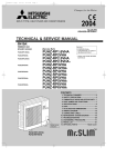
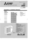
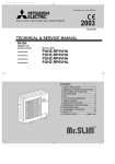
SPLIT-TYPE, HEAT PUMP AIR CONDITIONERS
TECHNICAL & SERVICE MANUAL
Series PEAD
R407C/R410A
<indoor unit> Service ref.
Models
• Refer to the OCT04 as for control
relation.This manual does not cover
outdoor units.
When servicing them, please refer
to the service manual
OC261 REVISED EDITION-B,
OC294 REVISED EDITION-A
and this manual as a set.
PEAD-RP1.6EA
PEAD-RP2EA
PEAD-RP2.5EA
PEAD-RP3EA1
PEAD-RP4EA1
PEAD-RP5EA1
PEAD-RP6EA1
CONTENTS
1. COMBINATION OF INDOOR AND
OUTDOOR UNITS ···································· 2
2. SAFETY PRECAUTION ···························· 3
3. PART NAMES AND FUNCTIONS ············· 5
4. SPECIFICATION ······································· 8
5. DATA ························································ 15
6. REFRIGERANT SYSTEM DIAGRAM ······ 38
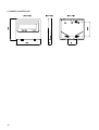
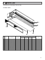
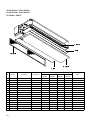
7. OUTLINES & DIMENSIONS ···················· 39
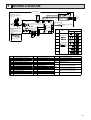
8. WIRING DIAGRAM ·································· 41
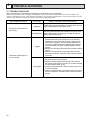
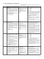
9. TROUBLE SHOOTING ···························· 42
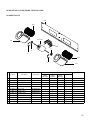
10. DISASSEMBLY INSTRUCTIONS ············ 51
11. PARTS LIST ············································· 53
12. OPTIONAL PARTS ·································· 59
INDOOR UNIT
TEMP.
ON/OFF
TM
REMOTE CONTROLLER
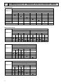
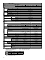
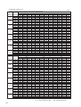
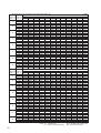
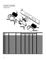
1 COMBINATION OF INDOOR AND OUTDOOR UNITS
(R410A Inverter)
Outdoor unit [OC294]
Heat pump type
Indoor unit
1.6VHA
PEAD-RP1.6EA
PEAD-RP2EA
PEAD-RP2.5EA
PEAD-RP3EA1
PEAD-RP4EA1
PEAD-RP5EA1
PEAD-RP6EA1
2VHA
2.5VHA
PUHZ-RP
3VHA
4VHA
5VHA
6VHA
—
—
—
—
—
—
—
—
—
—
—
—
—
—
—
—
—
—
—
—
—
—
—
—
—
—
—
—
—
—
—
—
—
—
—
—
—
—
—
—
—
—
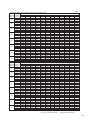
(R407C Fixed speed)
Outdoor unit [OC261 REVISED EDITION-B]
Heat pump type
Cooling only type
Indoor unit
PUH-P
2
1.6
2.5
PU-P
2
1.6
2.5
VGAA.UK YGAA.UK VGAA.UK YGAA.UK VGAA.UK YGAA.UK VGAA.UK YGAA.UK VGAA.UK YGAA.UK VGAA.UK YGAA.UK
VGAA1.UK YGAA1.UK VGAA1.UK YGAA1.UK VGAA1.UK YGAA1.UK VGAA1.UK YGAA1.UK VGAA1.UK YGAA1.UK VGAA1.UK YGAA1.UK
PEAD-RP1.6EA
PEAD-RP2EA
PEAD-RP2.5EA
—
—
—
—
—
—
—
—
—
—
—
—
—
—
—
—
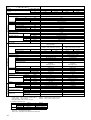
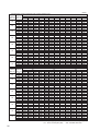
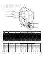
Outdoor unit [OC261 REVISED EDITION-B]
Heat pump type
PUH-P
Indoor unit
4
3
5
VGAA.UK YGAA.UK VGAA.UK YGAA.UK YGAA.UK
VGAA1.UK YGAA1.UK VGAA1.UK YGAA1.UK YGAA1.UK
PEAD-RP3EA1
PEAD-RP4EA1
PEAD-RP5EA1
PEAD-RP6EA1
—
—
—
—
—
—
—
—
—
—
—
—
—
—
6
YGAA.UK
YGAA1.UK
—
—
—
—
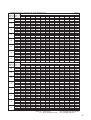
Outdoor unit [OC261 REVISED EDITION-B]
Cooling only type
PU-P
Indoor unit
3
4
5
VGAA.UK YGAA.UK VGAA.UK YGAA.UK YGAA.UK
VGAA1.UK YGAA1.UK VGAA1.UK YGAA1.UK YGAA1.UK
PEAD-RP3EA1
PEAD-RP4EA1
PEAD-RP5EA1
PEAD-RP6EA1
2
—
—
—
—
—
—
—
—
—
—
—
—
—
—
6
YGAA.UK
YGAA1.UK
—
—
—
—
—
—
—
—
—
—
—
—
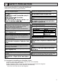
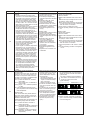
2 SAFETY PRECAUTION
CAUTIONS RELATED TO NEW REFRIGERANT
<Cautions for units utilizing refrigerant R410A>
Use new refrigerant pipes.
Do not use refrigerant other than R410A.
In case of using the existing pipes for R22, be careful with
If other refrigerant (R22 etc.) is used, chlorine in refrige-
the following.
rant can cause deterioration of refrigerant oil etc.
á For RP4 be sure to perform pipe replacement operation
before test run.
á Use flare nut as provided with this product.
Use a newly flared pipe.
á Avoid using thin pipes. For the detail, please refer to the
outdoor unit service manual No. OC294.
Use a vacuum pump with a reverse flow check
valve.
If no reverse flow check valve is used, vacuum pump oil
may flow back into refrigerant cycle and that can cause
deterioration of refrigerant oil etc.
Make sure that the inside and outside of refrigerant piping is clean and it has no contamination
such as sulfur which is hazardous for use,
oxides, dirt, shaving particles, etc.
In addition, use pipes with specified thickness.
Use the following tools specifically designed for
use with R410A refrigerant.
The following tools are necessary to use R410A refrigerant.
Tools (for R410A)
Gauge manifold
Flare tool
Contamination inside refrigerant piping can cause deterio-
Charge hose
Size adjustment gauge
ration of refrigerant oil etc.
Gas leak detector
Vacuum pump adaptor
Torque wrench
Electronic refrigerant
Store the piping to be used during installation
indoors and keep both ends of the piping sealed
until just before brazing. (Leave elbow joints, etc.
in their packaging.)
If dirt, dust or moisture enter into refrigerant cycle, that can
cause deterioration of refrigerant oil or malfunction of compressor.
Use ester oil, ether oil or alkylbenzene oil (small
amount) as the refrigerant oil applied to flares
and flange connections.
If large amount of mineral oil enter, that can cause deterioration of refrigerant oil etc.
Charge refrigerant from liquid phase of gas
cylinder.
If the refrigerant is charged from gas phase, composition
charging scale
Keep the tools with care.
If dirt, dust or moisture enter into refrigerant cycle, that can
cause deterioration of refrigerant oil or malfunction of compressor.
Do not use a charging cylinder without syphone
tube.
If a charging cylinder is used without syphone tube, the
composition of refrigerant will change and the efficiency
will be lowered.
Ventilate the room if refrigerant leaks during
operation. If refrigerant comes into contact with
a flame, poisonous gases will be released.
change may occur in refrigerant and the efficiency will be
lowered.
[1] Cautions for installing or relocation of unit
(1) Perform service after collecting the refrigerant left in unit completely.
(2) Do not release refrigerant in the air.
(3) After completing service, charge the system with the specified amount of refrigerant.
(4) When performing service, install a filter drier simultaneously.
Be sure to use a filter drier for new refrigerant.
3
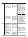
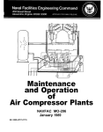
[2] Additional refrigerant charge
When charging directly from cylinder
Ensure that the cylinder for R410A is syphon type.
Charging should be performed with the syphon cylinder type stood vertically.
(Refrigerant must be charged from liquid phase.)
Unit
Gravimeter
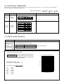
[3] Service tools
Use the below service tools as exclusive tools for R410A refrigerant.
No.
1
Specifications
Gauge manifold
• Only for R410A
• Use the existing fitting specifications. (UNF1/2)
• Use high-tension side pressure of 5.3MPa·G or over.
2
Charge hose
3
4
5
6
7
Electronic scale
• Only for R410A
• Use pressure performance of 5.09MPa·G or over.
Gas leak detector
• Use the detector for R134a, R407C or R410A.
Adaptor for reverse flow check
• Attach on vacuum pump.
Refrigerant charge base
Refrigerant cylinder
• Only for R410A
Top of cylinder (Pink)
Cylinder with syphon
8
4
Refrigerant recovery equipment
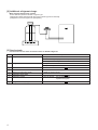
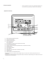
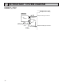
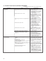
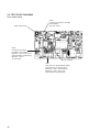
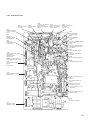
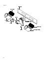
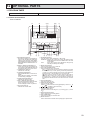
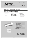
3 PART NAMES AND FUNCTIONS
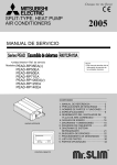
• Indoor Unit
Air intake (sucks the
air inside the room
into the unit)
Air outlet
In case of rear inlet
In case of bottom inlet
(Only 1.6~2.5HP)
5
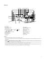
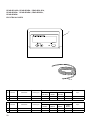
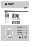
• Remote controller
•
Once the operation of the unit is set, subsequent operations can
be performed only by pressing the ON/OFF button repeatedly.
[Operation buttons]
CENTRALLY CONTROLLED
ON
1Hr.
OFF
˚C
CLOCK
CHECK
˚C
STAND BY
DEFROST
1
ERROR CODE
TEMP.
NOT AVAILABLE
FILTER
CHECK MODE
TEST RUN
FUNCTION
ON/OFF
B
2
3
FILTER
CHECK TEST
PAR-20MAA
A
0
TIMER SET
C
4 5 6 87 9
1
2
3
4
[Room temperature adjustment] Button
[Timer/continuous] Button
[Selecting operation] Button
[Time selection] Button
[Time-setting] Button
5
6
7
8
9
0
A
B
C
[Louver] Button (This button does not operate in this model)
[Fan speed adjustment] Button
[Up/down airflow direction] Button (This button does not operate in this model)
[Ventilation] Button
[Checking/built-in] Button
[Test run] Button
[Filter] Button (This button does not operate in this model)
[ON/OFF] Button
Position of built-in room temperature sensor
• Never expose the remote controller to direct sunlight. Doing so can result in the erroneous measurement of room
temperature.
• Never place any obstacle around the lower right-hand section of the remote controller. Doing so can result in the erroneous
measurement of room temperature.
6
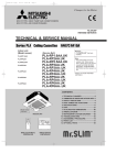
[Display]
DC B A UT Q S
CENTRALLY CONTROLLED
ON
E
F
˚C
˚C
STAND BY
DEFROST
G
F
G
H
I
J
OFF
CLOCK
CHECK
ERROR CODE
TEMP.
A Current time/Timer
B Centralized control
C Timer ON
D Abnormality occurs
E Operation mode:
COOL,
1Hr.
DRY,
H
AUTO,
FAN,
HEAT
Preparing for Heating mode
Defrost mode
Set temperature
Power ON
Louver
NOT AVAILABLE
FILTER
CHECK MODE
TEST RUN
FUNCTION
ON/OFF
R
P
O
N
M
IKLJ
K Not available function
L Ventilation
M Function setting mode
N Test run mode
O Error check mode
P Filter sign
Q Set effective for 1 hr.
R Sensor position
S Room temperature
T Airflow
U Fan speed
Caution
• Power ON display lights up when unit is in standby mode.
• When power is turned ON for the first time the (CENTRAL CTRL) display appears to go off momentarily but this is not a
malfunction.
• When the central control remote control unit, which is sold separately, is used the ON-OFF button, operation switch button and
TEMP, adjustment button do not operate.
• “NOT AVAILABLE” is displayed when the Airflow direction button or Louver button are pressed.This indicates that this room
unit is not equipped with the fan direction adjustment function and the louver function.
• When power is turned ON for the first time, it is normal that “H0” is displayed on the room temperature indication (For max.
2minutes). Please wait until this “H0” indication disappear’s then start the operation.
7
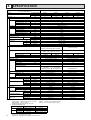
4 SPECIFICATION
Service Ref.
PEAD-RP1.6EA
Item
Function
Capacity
❇
INDOOR UNIT
❇1
Total input
Service Ref.
Power supply
❇3
Input
Running current ❇ 3
Starting current ❇ 3
External finish
Heat exchanger
Fan (drive) × No.
Fan
Fan motor output
Airflow (Lo-Hi)
External static pressure
Booster heater
❇3
Operation control & Thermostat
Noise level (Lo-Hi)
dB (A)
Unit drain pipe O.D
Dimensions
kW
A
A
kW
m3/min <CFM>
Pa
kW
30Pa
70Pa
mm (in.)
mm (in.)
mm (in.)
mm (in.)
kg (lbs)
W
D
H
OUTDOOR UNIT
Weight
PU(H)-P1.6VGAA/PU(H)-P1.6YGAA
PU(H)-P1.6VGAA1/PU(H)-P1.6YGAA1
PUHZ-RP1.6VHA
Power supply
Single phase, 50Hz, 220-240V /
3 phase , 50Hz, 380-415V (4 wires)
Single phase, 50Hz, 220-240V
kW
A
A
Input
Running current
Starting current
External finish
Refrigerant control
Compressor
Model
Motor output
Starter type
1.59
7.36/2.49
kW
Crankcase heater
Heat exchanger
Fan (drive) × No.
Fan
Fan motor output
Airflow
Defrost method
kW
m3/min (CFM)
Weight
Refrigerant
Charge
Oil (Model)
Pipe size O.D
Connection method
Between the indoor &
outdoor unit
Notes
Liquid
Gas
Indoor side
Outdoor side
Height difference
Piping length
dB (A)
dB (A)
mm (in.)
mm (in.)
mm (in.)
kg (lbs)
kg (lbs)
L
mm (in.)
mm (in.)
1. Rating Conditions (ISO 13253 T1)
Cooling: Indoor: D.B.27°C (80°F), W.B.19°C (66°F)
Heating: Indoor: D.B.20°C (68°F)
Refrigerant piping length (one way): 5m (16ft)
2. Guaranteed operating range
Cooling
Heating
Upper limit
Lower limit
Upper limit
Lower limit
Thermal relay
Internal thermostat
HP switch
HP switch
Discharge thermo
Discharge thermo
30
Plate fin coil
Propeller (direct) × 1
0.07
45 (1,590)
Reverse cycle
47
49
900 (35-7/16)
330+20 (13+1-3/4)
650 (25-5/8)
55 (121)
R407C
2.5 (5.5)
0.57 (Ester) MEL56
9.52 (3/8)
15.88 (5/8)
Flared
Flared
Max. 40m
Max. 40m
W
Cooling
Heating
W
D
H
Indoor
D.B.35°C, W.B.22.5°C
D.B.19°C, W.B.15°C
D.B.28°C
D.B.17°C
1.64
7.59/2.56
36/20
Munsell 5Y 7/1
Linear Expansion Valve
Hermetic
RE277VHSMT/RE277YFKM
1.3
Line start
Protection devices
Dimensions
REFRIGERANT PIPING
Heating
13,900
4,100
1.26
Cooling
Heating
12,200
16,500
3,600
4,850
1.12
1.73
PEAD-RP1.6EA
Single phase, 50Hz, 220-240V
0.13
0.55
0.8
Galvanized sheets
Plate fin coil
Centrifugal (direct) × 2
0.043
11-14<388-494>
30/70
–
Built in remote controller
34-38
36-43
R1 (External thread)
935 (36-13/16)
700 (27-5/8)
295 (11-5/8)
33 (73)
Service Ref.
Noise level
8
Cooling
15,100
4,450
1.71
Btu/h
W
kW
1
Outdoor:
Outdoor:
D.B.35°C (95°F), W.B.24°C (75°F)
D.B.7°C (45°F), W.B.6°C (43°F)
Outdoor
D.B.46°C
D.B.-5°C
D.B.24°C, W.B.18°C
D.B.-11°C, W.B.-12°C
3. Above data based on indicated voltage
Indoor Unit: Single phase 230V 50Hz
Outdoor Unit: Single phase 230V 50Hz/3 phase 400V 50Hz
0.91
4.01
0.96
4.23
13
Munsell 3Y 7.8/1.1
Linear Expansion Valve
Hermetic
SNB130FLBH
0.8
Line start
HP switch
Discharge thermo
–
Plate fin coil
Propeller (direct) × 1
0.043
35 (1,240)
Reverse cycle
44
46
800 (31-1/2)
300+23 (11-13/16+7/8)
600 (23-5/8)
45 (99)
R410A
2.5 (5.5)
0.45 (NEO22)
6.35 (1/4)
12.7 (1/2)
Max. 30m
Max. 50m
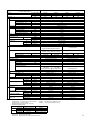
Service Ref.
PEAD-RP2EA
Item
Function
Capacity
❇
INDOOR UNIT
❇1
Total input
Service Ref.
Power supply
❇3
Input
Running current ❇ 3
Starting current ❇ 3
External finish
Heat exchanger
Fan (drive) × No.
Fan
Fan motor output
Airflow (Lo-Hi)
External static pressure
Booster heater
❇3
Operation control & Thermostat
Noise level (Lo-Hi)
dB (A)
Unit drain pipe O.D
Dimensions
kW
A
A
kW
m3/min <CFM>
Pa
kW
30Pa
70Pa
mm (in.)
mm (in.)
mm (in.)
mm (in.)
kg (lbs)
W
D
H
OUTDOOR UNIT
Weight
Heating
20,400
6,000
1.65
Cooling
16,700
4,900
1.52
PEAD-RP2EA
Single phase, 50Hz, 220-240V
0.14
0.61
0.9
Galvanized sheets
Plate fin coil
Centrifugal (direct) × 2
0.076
13.5-17<477-600>
30/70
–
Built in remote controller
36-40
38-44
R1 (External thread)
935 (36-13/16)
700 (27-5/8)
295 (11-5/8)
35 (77)
Heating
21,400
6,300
2.20
Service Ref.
PU(H)-P2VGAA/PU(H)-P2YGAA
PU(H)-P2VGAA1/PU(H)-P2YGAA1
PUHZ-RP2VHA
Power supply
Single phase, 50Hz, 220-240V /
3 phase , 50Hz, 380-415V (4 wires)
Single phase, 50Hz, 220-240V
kW
A
A
Input
Running current
Starting current
External finish
Refrigerant control
Compressor
Model
Motor output
Starter type
2.29
10.26/3.70
kW
Crankcase heater
Heat exchanger
Fan (drive) × No.
Fan
Fan motor output
Airflow
Defrost method
Dimensions
kW
m3/min (CFM)
Weight
Refrigerant
Charge
Oil (Model)
Pipe size O.D
Connection method
Between the indoor &
outdoor unit
Notes
Liquid
Gas
Indoor side
Outdoor side
Height difference
Piping length
dB (A)
dB (A)
mm (in.)
mm (in.)
mm (in.)
kg (lbs)
kg (lbs)
L
mm (in.)
mm (in.)
1. Rating Conditions (ISO 13253 T1)
Cooling: Indoor: D.B.27°C (80°F), W.B.19°C (66°F)
Heating: Indoor: D.B.20°C (68°F)
Refrigerant piping length (one way): 5m (16ft)
2. Guaranteed operating range
Cooling
Heating
Upper limit
Lower limit
Upper limit
Lower limit
Thermal relay
Internal thermostat
HP switch
HP switch
Discharge thermo
Discharge thermo
38
Plate fin coil
Propeller (direct) × 1
0.07
55 (1,940)
Reverse cycle
48
49
900 (35-7/16)
330+20 (13+1-3/4)
855 (33-5/8)
71 (157)
R407C
2.6 (5.7)
1.2 (Ester) MEL56
9.52 (3/8)
15.88 (5/8)
Flared
Flared
Max. 40m
Max. 40m
W
Cooling
Heating
W
D
H
Indoor
D.B.35°C, W.B.22.5°C
D.B.19°C, W.B.15°C
D.B.28°C
D.B.17°C
2.36
10.57/3.82
62/31
Munsell 5Y 7/1
Linear Expansion Valve
Hermetic
NE36VMJMT/NE36YEKMT
1.6
Line start
Protection devices
Noise level
REFRIGERANT PIPING
Cooling
19,100
5,600
2.53
Btu/h
W
kW
1
Outdoor:
Outdoor:
1.39
6.16
1.46
6.47
13
Munsell 3Y 7.8/1.1
Linear Expansion Valve
Hermetic
SNB130FLBH
1.1
Line start
HP switch
Discharge thermo
–
Plate fin coil
Propeller (direct) × 1
0.043
35 (1,240)
Reverse cycle
44
46
800 (31-1/2)
300+23 (11-13/16+7/8)
600 (23-5/8)
45 (99)
R410A
2.5 (5.5)
0.45 (NEO22)
6.35 (1/4)
12.7 (1/2)
Max. 30m
Max. 50m
D.B.35°C (95°F), W.B.24°C (75°F)
D.B.7°C (45°F), W.B.6°C (43°F)
Outdoor
D.B.46°C
D.B.-5°C
D.B.24°C, W.B.18°C
D.B.-11°C, W.B.-12°C
3. Above data based on indicated voltage
Indoor Unit: Single phase 230V 50Hz
Outdoor Unit: Single phase 230V 50Hz/3 phase 400V 50Hz
9
Service Ref.
PEAD-RP2.5EA
Item
Function
Capacity
❇
Btu/h
W
kW
1
INDOOR UNIT
❇1
Total input
Service Ref.
Power supply
❇3
Input
Running current ❇ 3
Starting current ❇ 3
External finish
Heat exchanger
Fan (drive) × No.
Fan
Fan motor output
Airflow (Lo-Hi)
External static pressure
Booster heater
❇3
Operation control & Thermostat
Noise level (Lo-Hi)
dB (A)
Unit drain pipe O.D
Dimensions
kW
A
A
kW
m3/min <CFM>
Pa
kW
30Pa
70Pa
mm (in.)
mm (in.)
mm (in.)
mm (in.)
kg (lbs)
W
D
H
OUTDOOR UNIT
Weight
PU(H)-P2.5VGAA/PU(H)-P2.5YGAA
PU(H)-P2.5VGAA1/PU(H)-P2.5YGAA1
PUHZ-RP2.5VHA
Power supply
Single phase, 50Hz, 220-240V /
3 phase , 50Hz, 380-415V (4 wires)
Single phase, 50Hz, 220-240V
kW
A
A
Input
Running current
Starting current
External finish
Refrigerant control
Compressor
Model
Motor output
Starter type
2.77
11.90/4.48
kW
Crankcase heater
Heat exchanger
Fan (drive) × No.
Fan
Fan motor output
Airflow
Defrost method
kW
m3/min (CFM)
Weight
Refrigerant
Charge
Oil (Model)
Pipe size O.D
Connection method
Between the indoor &
outdoor unit
Notes
Liquid
Gas
Indoor side
Outdoor side
Height difference
Piping length
dB (A)
dB (A)
mm (in.)
mm (in.)
mm (in.)
kg (lbs)
kg (lbs)
L
mm (in.)
mm (in.)
1. Rating Conditions (ISO 13253 T1)
Cooling: Indoor: D.B.27°C (80°F), W.B.19°C (66°F)
Heating: Indoor: D.B.20°C (68°F)
Refrigerant piping length (one way): 5m (16ft)
2. Guaranteed operating range
Cooling
Heating
Upper limit
Lower limit
Upper limit
Lower limit
Thermal relay
Internal thermostat
HP switch
HP switch
Discharge thermo
Discharge thermo
38
Plate fin coil
Propeller (direct) × 1
0.07
50 (1,770)
Reverse cycle
48
50
900 (35-7/16)
330+20 (13+1-3/4)
855 (33-5/8)
82 (181)
R407C
3.1 (6.8)
1.2 (Ester) MEL56
9.52 (3/8)
15.88 (5/8)
Flared
Flared
Max. 50m
Max. 50m
W
Cooling
Heating
W
D
H
Indoor
D.B.35°C, W.B.22.5°C
D.B.19°C, W.B.15°C
D.B.28°C
D.B.17°C
2.68
11.51/4.34
77/35
Munsell 5Y 7/1
Linear Expansion Valve
Hermetic
NE41VMJMT/NE41YEKMT
1.9
Line start
Protection devices
Dimensions
Outdoor:
Outdoor:
D.B.35°C (95°F), W.B.24°C (75°F)
D.B.7°C (45°F), W.B.6°C (43°F)
Outdoor
D.B.46°C
D.B.-5°C
D.B.24°C, W.B.18°C
D.B.-11°C, W.B.-12°C
3. Above data based on indicated voltage
Indoor Unit: Single phase 230V 50Hz
Outdoor Unit: Single phase 230V 50Hz/3 phase 400V 50Hz
10
Heating
23,800
7,000
1.90
Cooling
Heating
20,400
24,300
6,000
7,150
1.86
2.36
PEAD-RP2.5EA
Single phase, 50Hz, 220-240V
0.16
0.70
1.0
Galvanized sheets
Plate fin coil
Centrifugal (direct) × 2
0.116
17-21<600-741>
30/70
–
Built in remote controller
37-41
39-46
R1 (External thread)
1,175 (46-1/8)
700 (27-5/8)
295 (11-5/8)
42 (92)
Service Ref.
Noise level
REFRIGERANT PIPING
Cooling
22,500
6,600
2.65
1.49
6.61
1.69
7.50
19
Munsell 3Y 7.8/1.1
Linear Expansion Valve
Hermetic
TNB220FMBH
1.6
Line start
HP switch
Discharge thermo
–
Plate fin coil
Propeller (direct) × 1
0.06
55 (1,940)
Reverse cycle
47
48
950 (37-3/8)
330+30 (13+1-3/16)
943 (37-1/8)
75 (165)
R410A
3.5 (7.7)
0.87 (NEO22)
Max. 30m
Max. 50m
Service Ref.
PEAD-RP3EA1
Item
Function
Capacity
❇
Btu/h
W
kW
1
INDOOR UNIT
❇1
Total input
Service Ref.
Power supply
❇3
Input
Running current ❇ 3
Starting current ❇ 3
External finish
Heat exchanger
Fan (drive) × No.
Fan
Fan motor output
Airflow (Lo-Hi)
External static pressure
Booster heater
❇3
Operation control & Thermostat
Noise level (Lo-Hi)
dB (A)
Unit drain pipe O.D
Dimensions
kW
A
A
kW
m3/min <CFM>
Pa
kW
70Pa
(130Pa)
mm (in.)
mm (in.)
mm (in.)
mm (in.)
kg (lbs)
W
D
H
OUTDOOR UNIT
Weight
Heating
27,200
8,000
2.34
Cooling
Heating
24,200
30,800
7,100
9,050
2.15
3.18
PEAD-RP3EA1
Single phase, 50Hz, 220-240V
0.35
1.55
2.0
Galvanized sheets
Plate fin coil
Centrifugal (direct) × 2
0.15
20-25<706-883>
70/(130)
–
Built in remote controller
37-41
40-45
R1 (External thread)
1,175 (46-1/8)
740 (29-1/8)
325 (12-13/16)
44 (97)
Service Ref.
PU(H)-P3VGAA/PU(H)-P3YGAA
PU(H)-P3VGAA1/PU(H)-P3YGAA1
PUHZ-RP3VHA
Power supply
Single phase, 50Hz, 220-240V /
3 phase , 50Hz, 380-415V (4 wires)
Single phase, 50Hz, 220-240V
kW
A
A
Input
Running current
Starting current
External finish
Refrigerant control
Compressor
Model
Motor output
Starter type
3.27
14.81/5.29
kW
Crankcase heater
Heat exchanger
Fan (drive) × No.
Fan
Fan motor output
Airflow
Defrost method
Dimensions
kW
m3/min (CFM)
Weight
Refrigerant
Charge
Oil (Model)
Pipe size O.D
Connection method
Between the indoor &
outdoor unit
Notes
Liquid
Gas
Indoor side
Outdoor side
Height difference
Piping length
dB (A)
dB (A)
mm (in.)
mm (in.)
mm (in.)
kg (lbs)
kg (lbs)
L
mm (in.)
mm (in.)
1. Rating Conditions (ISO 13253 T1)
Cooling: Indoor: D.B.27°C (80°F), W.B.19°C (66°F)
Heating: Indoor: D.B.20°C (68°F)
Refrigerant piping length (one way): 5m (16ft)
2. Guaranteed operating range
Cooling
Heating
Upper limit
Lower limit
Upper limit
Lower limit
Thermal relay
Internal thermostat
HP switch
HP switch
Discharge thermo
Discharge thermo
38
Plate fin coil
Propeller (direct) × 1
0.07
50 (1,770)
Reverse cycle
49
51
900 (35-7/16)
330+20 (13+1-3/4)
855 (33-5/8)
82 (181)
R407C
3.3 (7.3)
1.3 (Ester) MEL56
9.52 (3/8)
15.88 (5/8)
Flared
Flared
Max. 50m
Max. 50m
W
Cooling
Heating
W
D
H
Indoor
D.B.35°C, W.B.22.5°C
D.B.19°C, W.B.15°C
D.B.28°C
D.B.17°C
3.48
15.76/5.63
93/47
Munsell 5Y 7/1
Linear Expansion Valve
Hermetic
NE52VNJMT/NE52YDKMT
2.5
Line start
Protection devices
Noise level
REFRIGERANT PIPING
Cooling
25,900
7,600
3.35
Outdoor:
Outdoor:
1.81
8.04
2.18
9.70
19
Munsell 3Y 7.8/1.1
Linear Expansion Valve
Hermetic
TNB220FMBH
1.6
Line start
HP switch
Discharge thermo
–
Plate fin coil
Propeller (direct) × 1
0.06
55 (1,940)
Reverse cycle
47
48
950 (37-3/8)
330+30 (13+1-3/16)
943 (37-1/8)
75 (165)
R410A
3.5 (7.7)
0.87 (NEO22)
Max. 30m
Max. 50m
D.B.35°C (95°F), W.B.24°C (75°F)
D.B.7°C (45°F), W.B.6°C (43°F)
Outdoor
D.B.46°C
D.B.-5°C
D.B.24°C, W.B.18°C
D.B.-11°C, W.B.-12°C
3. Above data based on indicated voltage
Indoor Unit: Single phase 230V 50Hz
Outdoor Unit: Single phase 230V 50Hz/3 phase 400V 50Hz
11
Service Ref.
PEAD-RP4EA1
Item
Function
Capacity
❇
Btu/h
W
kW
1
INDOOR UNIT
❇1
Total input
Service Ref.
Power supply
❇3
Input
Running current ❇ 3
Starting current ❇ 3
External finish
Heat exchanger
Fan (drive) × No.
Fan
Fan motor output
Airflow (Lo-Hi)
External static pressure
Booster heater
❇3
Operation control & Thermostat
Noise level (Lo-Hi)
dB (A)
Unit drain pipe O.D
Dimensions
kW
A
A
kW
m3/min <CFM>
Pa
kW
70Pa
(130Pa)
mm (in.)
mm (in.)
mm (in.)
mm (in.)
kg (lbs)
W
D
H
OUTDOOR UNIT
Weight
PU(H)-P4VGAA/PU(H)-P4YGAA
PU(H)-P4VGAA1/PU(H)-P4YGAA1
PUHZ-RP4VHA
Power supply
Single phase, 50Hz, 220-240V /
3 phase , 50Hz, 380-415V (4 wires)
Single phase, 50Hz, 220-240V
kW
A
A
Input
Running current
Starting current
External finish
Refrigerant control
Compressor
Model
Motor output
Starter type
3.43
15.71/5.55
kW
Crankcase heater
Heat exchanger
Fan (drive) × No.
Fan
Fan motor output
Airflow
Defrost method
kW
m3/min (CFM)
Weight
Refrigerant
Charge
Oil (Model)
Pipe size O.D
Connection method
Between the indoor &
outdoor unit
Notes
Liquid
Gas
Indoor side
Outdoor side
Height difference
Piping length
dB (A)
dB (A)
mm (in.)
mm (in.)
mm (in.)
kg (lbs)
kg (lbs)
L
mm (in.)
mm (in.)
1. Rating Conditions (ISO 13253 T1)
Cooling: Indoor: D.B.27°C (80°F), W.B.19°C (66°F)
Heating: Indoor: D.B.20°C (68°F)
Refrigerant piping length (one way): 5m (16ft)
2. Guaranteed operating range
Cooling
Heating
Upper limit
Lower limit
Upper limit
Lower limit
Thermal relay
Internal thermostat
HP switch
HP switch
Discharge thermo
Discharge thermo
38
Plate fin coil
Propeller (direct) × 2
0.07+0.07
85 (3,000)
Reverse cycle
51
53
900 (35-7/16)
330+20 (13+1-3/4)
1,260 (49-5/8)
96 (212)
R407C
4.0 (8.8)
1.3 (Ester) MEL56
9.52 (3/8)
19.05 (3/4)
Flared
Flared
Max. 50m
Max. 50m
W
Cooling
Heating
W
D
H
Indoor
D.B.35°C, W.B.22.5°C
D.B.19°C, W.B.15°C
D.B.28°C
D.B.17°C
3.62
16.58/5.86
99/49
Munsell 5Y 7/1
Linear Expansion Valve
Hermetic
NE56VNJMT/NE56YDKMT
2.7
Line start
Protection devices
Dimensions
Outdoor:
Outdoor:
D.B.35°C (95°F), W.B.24°C (75°F)
D.B.7°C (45°F), W.B.6°C (43°F)
Outdoor
D.B.46°C
D.B.-5°C
D.B.24°C, W.B.18°C
D.B.-11°C, W.B.-12°C
3. Above data based on indicated voltage
Indoor Unit: Single phase 230V 50Hz
Outdoor Unit: Single phase 230V 50Hz/3 phase 400V 50Hz
12
Heating
38,200
11,200
3.48
Cooling
Heating
34,100
35,100
10,000
10,300
3.08
4.00
PEAD-RP4EA1
Single phase, 50Hz, 220-240V
0.57
2.53
3.2
Galvanized sheets
Plate fin coil
Centrifugal (direct) × 2
0.24
27-34<953-1,200>
70/(130)
–
Built in remote controller
41-46
42-48
R1 (External thread)
1,415 (55-11/16)
740 (29-1/8)
325 (12-13/16)
62 (136)
Service Ref.
Noise level
REFRIGERANT PIPING
Cooling
32,700
9,600
3.83
2.78
12.33
3.14
13.94
28
Munsell 3Y 7.8/1.1
Linear Expansion Valve
Hermetic
ANV33FDAMT
1.9
Line start
HP switch
LP switch
Discharge thermo
–
Plate fin coil
Propeller (direct) × 2
0.06+0.06
100 (3,530)
Reverse cycle
49
51
950 (37-3/8)
330+30 (13+1-3/16)
1,350 (53-1/8)
121 (267)
R410A
5.5 (12.1)
1.4 (MEL56)
15.88 (5/8)
Max. 30m
Max. 75m
Service Ref.
PEAD-RP5EA1
Item
Function
Capacity
❇
Btu/h
W
kW
1
❇1
Total input
Service Ref.
Power supply
INDOOR UNIT
Cooling
41,600
12,200
4.87
❇3
Input
Running current ❇ 3
Starting current ❇ 3
External finish
Heat exchanger
Fan (drive) × No.
Fan
Fan motor output
Airflow (Lo-Hi)
External static pressure
Booster heater
❇3
Operation control & Thermostat
Noise level (Lo-Hi)
dB (A)
Unit drain pipe O.D
Dimensions
kW
A
A
kW
m3/min <CFM>
Pa
kW
70Pa
(130Pa)
mm (in.)
mm (in.)
mm (in.)
mm (in.)
kg (lbs)
W
D
H
Weight
Service Ref.
PU(H)-P5YGAA
PU(H)-P5YGAA1
Power supply
kW
A
A
OUTDOOR UNIT
Input
Running current
Starting current
External finish
Refrigerant control
Compressor
Model
Motor output
Starter type
Protection devices
Crankcase heater
Heat exchanger
Fan (drive) × No.
Fan
Fan motor output
Airflow
Defrost method
W
kW
m3/min (CFM)
Cooling
Heating
W
D
H
Noise level
Dimensions
REFRIGERANT PIPING
kW
Weight
Refrigerant
Charge
Oil (Model)
Pipe size O.D
Connection method
Between the indoor &
outdoor unit
Notes
Liquid
Gas
Indoor side
Outdoor side
Height difference
Piping length
dB (A)
dB (A)
mm (in.)
mm (in.)
mm (in.)
kg (lbs)
kg (lbs)
L
mm (in.)
mm (in.)
Heating
Upper limit
Lower limit
Upper limit
Lower limit
Indoor
D.B.35°C, W.B.22.5°C
D.B.19°C, W.B.15°C
D.B.28°C
D.B.17°C
PUHZ-RP5VHA
3 phase , 50Hz, 380-415V (4 wires)
5.04
4.70
8.15
7.60
65.5
Munsell 5Y 7/1
Linear Expansion Valve
Hermetic
ZR61KCE-TFD-230 (YGAA)
ZR61KCW-TFD-522 (YGAA1)
3.5
Line start
Single phase, 50Hz, 220-240V
3.56
3.14
15.80
13.94
28
Munsell 3Y 7.8/1.1
Linear Expansion Valve
Hermetic
Internal thermostat, Thermal relay
HP switch
Discharge thermo
38
Plate fin coil
Propeller (direct) × 2
0.07+0.07
95 (3,360)
Reverse cycle
55
56
1,050 (41-5/16)
330+20 (13+1-3/4)
1,260 (49-5/8)
122 (269)
R407C
4.6 (10.1)
1.690 (Ester) 3MAW-POE
HP switch
LP switch
Discharge thermo
–
Plate fin coil
Propeller (direct) × 2
0.06+0.06
100 (3,530)
Reverse cycle
49
51
950 (37-3/8)
330+30 (13+1-3/16)
1,350 (53-1/8)
121 (267)
R410A
5.5 (12.1)
1.4 (MEL56)
ANV33FDAMT
2.4
Line start
9.52 (3/8)
19.05 (3/4)
15.88 (5/8)
Flared
Flared
Max. 50m
Max. 50m
1. Rating Conditions (ISO 13253 T1)
Cooling: Indoor: D.B.27°C (80°F), W.B.19°C (66°F)
Heating: Indoor: D.B.20°C (68°F)
Refrigerant piping length (one way): 5m (16ft)
2. Guaranteed operating range
Cooling
Heating
47,700
14,000
4.11
Cooling
Heating
42,600
47,700
12,500
14,000
3.69
4.74
PEAD-RP5EA1
Single phase, 50Hz, 220-240V
0.59
2.62
3.4
Galvanized sheets
Plate fin coil
Centrifugal (direct) × 2
0.27
33.5-42<1,183-1,483>
70/(130)
–
Built in remote controller
44-50
46-52
R1 (External thread)
1,415 (55-11/16)
740 (29-1/8)
325 (12-13/16)
65 (143)
Outdoor:
Outdoor:
Max. 30m
Max. 75m
D.B.35°C (95°F), W.B.24°C (75°F)
D.B.7°C (45°F), W.B.6°C (43°F)
Outdoor
D.B.46°C
D.B.-5°C
D.B.24°C, W.B.18°C
D.B.-11°C, W.B.-12°C
3. Above data based on indicated voltage
Indoor Unit: Single phase 230V 50Hz
Outdoor Unit: Single phase 230V 50Hz/3 phase 400V 50Hz
13
Service Ref.
PEAD-RP6EA1
Item
Function
Capacity
❇
Btu/h
W
kW
1
❇1
Total input
Service Ref.
Power supply
INDOOR UNIT
Cooling
47,700
14,000
5.81
❇3
Input
Running current ❇ 3
Starting current ❇ 3
External finish
Heat exchanger
Fan (drive) × No.
Fan
Fan motor output
Airflow (Lo-Hi)
External static pressure
Booster heater
❇3
Operation control & Thermostat
Noise level (Lo-Hi)
dB (A)
Unit drain pipe O.D
Dimensions
kW
A
A
kW
m3/min <CFM>
Pa
kW
70Pa
(130Pa)
mm (in.)
mm (in.)
mm (in.)
mm (in.)
kg (lbs)
W
D
H
Weight
Service Ref.
OUTDOOR UNIT
Power supply
REFRIGERANT PIPING
Between the indoor &
outdoor unit
Notes
Liquid
Gas
Indoor side
Outdoor side
Height difference
Piping length
Heating
Upper limit
Lower limit
Upper limit
Lower limit
38
Plate fin coil
Propeller (direct) × 2
0.07+0.07
100 (3,530)
Reverse cycle
57
58
1,050 (41-5/16)
330+20 (13+1-3/4)
1,260 (49-5/8)
122 (269)
R407C
4.9 (10.8)
1.774 (Ester) 3MAW-POE
–
Plate fin coil
Propeller (direct) × 2
0.06+0.06
100 (3,530)
Reverse cycle
49
51
950 (37-3/8)
330+30 (13+1-3/16)
1,350 (53-1/8)
121 (267)
R410A
5.5 (12.1)
1.4 (MEL56)
9.52 (3/8)
19.05 (3/4)
15.88 (5/8)
Flared
Flared
Max. 50m
Max. 50m
Outdoor:
Outdoor:
D.B.35°C (95°F), W.B.24°C (75°F)
D.B.7°C (45°F), W.B.6°C (43°F)
Outdoor
D.B.46°C
D.B.-5°C
D.B.24°C, W.B.18°C
D.B.-11°C, W.B.-12°C
3. Above data based on indicated voltage
Indoor Unit: Single phase 230V 50Hz
Outdoor Unit: Single phase 230V 50Hz/3 phase 400V 50Hz
14
HP switch
LP switch
Discharge thermo
kg (lbs)
L
mm (in.)
mm (in.)
Indoor
D.B.35°C, W.B.22.5°C
D.B.19°C, W.B.15°C
D.B.28°C
D.B.17°C
4.58
20.37
Internal thermostat, Thermal relay
HP switch
Discharge thermo
dB (A)
dB (A)
mm (in.)
mm (in.)
mm (in.)
kg (lbs)
1. Rating Conditions (ISO 13253 T1)
Cooling: Indoor: D.B.27°C (80°F), W.B.19°C (66°F)
Heating: Indoor: D.B.20°C (68°F)
Refrigerant piping length (one way): 5m (16ft)
2. Guaranteed operating range
Cooling
4.66
20.73
30
Munsell 3Y 7.8/1.1
Linear Expansion Valve
Hermetic
ANV33FDAMT
2.9
Line start
kW
Charge
Oil (Model)
5.91
9.56
74
Munsell 5Y 7/1
Linear Expansion Valve
Hermetic
ZR72KCW-TFD-522
4.2
Line start
m3/min (CFM)
Weight
Refrigerant
Connection method
Single phase, 50Hz, 220-240V
W
Cooling
Heating
W
D
H
Pipe size O.D
3 phase , 50Hz, 380-415V (4 wires)
kW
Crankcase heater
Heat exchanger
Fan (drive) × No.
Fan
Fan motor output
Airflow
Defrost method
Dimensions
PUHZ-RP6VHA
5.58
9.03
Protection devices
Noise level
PU(H)-P6YGAA
PU(H)-P6YGAA1
kW
A
A
Input
Running current
Starting current
External finish
Refrigerant control
Compressor
Model
Motor output
Starter type
Heating
54,500
16,000
4.76
Cooling
Heating
47,700
56,600
14,000
16,600
4.91
5.90
PEAD-RP6EA1
Single phase, 50Hz, 220-240V
0.61
2.69
3.5
Galvanized sheets
Plate fin coil
Centrifugal (direct) × 2
0.27
36.5-46<1,288-1,624>
70/(130)
–
Built in remote controller
46-51
47-53
R1 (External thread)
1,715 (67-1/2)
740 (29-1/8)
325 (12-13/16)
70 (154)
Max. 30m
Max. 75m
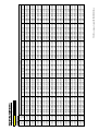
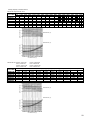
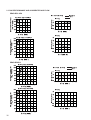
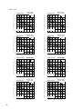
COOLING Capacity
Indoor
Indoor
intake air intake air
DB℃
WB℃
20
16
20
18
20
20
22
16
22
18
22
20
24
16
24
18
24
20
24
22
26
16
26
18
26
20
26
22
27
16
27
18
27
20
27
22
28
16
28
18
28
20
28
22
30
16
30
18
30
20
30
22
32
16
32
18
32
20
32
22
34
16
34
18
34
20
34
22
PEAD-RP1.6EA
CA
3564
3816
4104
3564
3816
4104
3564
3816
4104
4374
3564
3816
4104
4374
3564
3816
4104
4374
3564
3816
4104
4374
3564
3816
4104
4374
3564
3816
4104
4374
3564
3816
4104
4374
Capa
3600
20
SHC (W)
2780
2519
2216
3065
2824
2544
3350
3129
2873
2537
3564
3434
3201
2887
3564
3587
3365
3062
3564
3740
3529
3237
3564
3816
3858
3587
3564
3816
4104
3937
3564
3816
4104
4287
Input
1.12
SHF
0.78
0.66
0.54
0.86
0.74
0.62
0.94
0.82
0.70
0.58
1.00
0.90
0.78
0.66
1.00
0.94
0.82
0.70
1.00
0.98
0.86
0.74
1.00
1.00
0.94
0.82
1.00
1.00
1.00
0.90
1.00
1.00
1.00
0.98
SHF
0.88
PEAD-RP1.6EA / PUHZ-RP1.6VHA
P.C.
0.90
0.91
0.94
0.90
0.91
0.94
0.90
0.91
0.94
0.96
0.90
0.91
0.94
0.96
0.90
0.91
0.94
0.96
0.90
0.91
0.94
0.96
0.90
0.91
0.94
0.96
0.90
0.91
0.94
0.96
0.90
0.91
0.94
0.96
CA
3456
3708
4014
3456
3708
4014
3456
3708
4014
4284
3456
3708
4014
4284
3456
3708
4014
4284
3456
3708
4014
4284
3456
3708
4014
4284
3456
3708
4014
4284
3456
3708
4014
4284
25
SHC (W)
2696
2447
2168
2972
2744
2489
3249
3041
2810
2485
3456
3337
3131
2827
3456
3486
3291
2999
3456
3634
3452
3170
3456
3708
3773
3513
3456
3708
4014
3856
3456
3708
4014
4198
SHF
0.78
0.66
0.54
0.86
0.74
0.62
0.94
0.82
0.70
0.58
1.00
0.90
0.78
0.66
1.00
0.94
0.82
0.70
1.00
0.98
0.86
0.74
1.00
1.00
0.94
0.82
1.00
1.00
1.00
0.90
1.00
1.00
1.00
0.98
P.C.
0.95
0.96
0.99
0.95
0.96
0.99
0.95
0.96
0.99
1.02
0.95
0.96
0.99
1.02
0.95
0.96
0.99
1.02
0.95
0.96
0.99
1.02
0.95
0.96
0.99
1.02
0.95
0.96
0.99
1.02
0.95
0.96
0.99
1.02
CA
3348
3582
3906
3348
3582
3906
3348
3582
3906
4176
3348
3582
3906
4176
3348
3582
3906
4176
3348
3582
3906
4176
3348
3582
3906
4176
3348
3582
3906
4176
3348
3582
3906
4176
30
SHC (W)
2611
2364
2109
2879
2651
2422
3147
2937
2734
2422
3348
3224
3047
2756
3348
3367
3203
2923
3348
3510
3359
3090
3348
3582
3672
3424
3348
3582
3906
3758
3348
3582
3906
4092
SHF
0.78
0.66
0.54
0.86
0.74
0.62
0.94
0.82
0.70
0.58
1.00
0.90
0.78
0.66
1.00
0.94
0.82
0.70
1.00
0.98
0.86
0.74
1.00
1.00
0.94
0.82
1.00
1.00
1.00
0.90
1.00
1.00
1.00
0.98
P.C.
1.00
1.03
1.05
1.00
1.03
1.05
1.00
1.03
1.05
1.09
1.00
1.03
1.05
1.09
1.00
1.03
1.05
1.09
1.00
1.03
1.05
1.09
1.00
1.03
1.05
1.09
1.00
1.03
1.05
1.09
1.00
1.03
1.05
1.09
35
CA SHC (W)
3204
2499
3456
2281
3744
2022
3204
2755
3456
2557
3744
2321
3204
3012
3456
2834
3744
2621
4032
2339
3204
3204
3456
3110
3744
2920
4032
2661
3204
3204
3456
3249
3744
3070
4032
2822
3204
3204
3456
3387
3744
3220
4032
2984
3204
3204
3456
3456
3744
3519
4032
3306
3204
3204
3456
3456
3744
3744
4032
3629
3204
3204
3456
3456
3744
3744
4032
3951
Outdoor intake air DB℃
SHF
0.78
0.66
0.54
0.86
0.74
0.62
0.94
0.82
0.70
0.58
1.00
0.90
0.78
0.66
1.00
0.94
0.82
0.70
1.00
0.98
0.86
0.74
1.00
1.00
0.94
0.82
1.00
1.00
1.00
0.90
1.00
1.00
1.00
0.98
P.C.
1.08
1.10
1.13
1.08
1.10
1.13
1.08
1.10
1.13
1.15
1.08
1.10
1.13
1.15
1.08
1.10
1.13
1.15
1.08
1.10
1.13
1.15
1.08
1.10
1.13
1.15
1.08
1.10
1.13
1.15
1.08
1.10
1.13
1.15
SHF
0.78
0.66
0.54
0.86
0.74
0.62
0.94
0.82
0.70
0.58
1.00
0.90
0.78
0.66
1.00
0.94
0.82
0.70
1.00
0.98
0.86
0.74
1.00
1.00
0.94
0.82
1.00
1.00
1.00
0.90
1.00
1.00
1.00
0.98
P.C.
1.15
1.19
1.21
1.15
1.19
1.21
1.15
1.19
1.21
1.24
1.15
1.19
1.21
1.24
1.15
1.19
1.21
1.24
1.15
1.19
1.21
1.24
1.15
1.19
1.21
1.24
1.15
1.19
1.21
1.24
1.15
1.19
1.21
1.24
45
CA SHC (W)
2916
2274
3132
2067
3384
1827
2916
2508
3132
2318
3384
2098
2916
2741
3132
2568
3384
2369
3672
2130
2916
2916
3132
2819
3384
2640
3672
2424
2916
2916
3132
2944
3384
2775
3672
2570
2916
2916
3132
3069
3384
2910
3672
2717
2916
2916
3132
3132
3384
3181
3672
3011
2916
2916
3132
3132
3384
3384
3672
3305
2916
2916
3132
3132
3384
3384
3672
3599
SHF
0.78
0.66
0.54
0.86
0.74
0.62
0.94
0.82
0.70
0.58
1.00
0.90
0.78
0.66
1.00
0.94
0.82
0.70
1.00
0.98
0.86
0.74
1.00
1.00
0.94
0.82
1.00
1.00
1.00
0.90
1.00
1.00
1.00
0.98
PEAD1.6_cooling_matrixdata_INV_PEAD(E)041028.xls
40
CA SHC (W)
3060
2387
3348
2210
3600
1944
3060
2632
3348
2478
3600
2232
3060
2876
3348
2745
3600
2520
3888
2255
3060
3060
3348
3013
3600
2808
3888
2566
3060
3060
3348
3147
3600
2952
3888
2722
3060
3060
3348
3281
3600
3096
3888
2877
3060
3060
3348
3348
3600
3384
3888
3188
3060
3060
3348
3348
3600
3600
3888
3499
3060
3060
3348
3348
3600
3600
3888
3810
P.C.
1.25
1.28
1.30
1.25
1.28
1.30
1.25
1.28
1.30
1.32
1.25
1.28
1.30
1.32
1.25
1.28
1.30
1.32
1.25
1.28
1.30
1.32
1.25
1.28
1.30
1.32
1.25
1.28
1.30
1.32
1.25
1.28
1.30
1.32
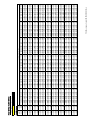
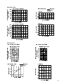
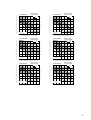
COOLING Capacity
Indoor
Indoor
intake air intake air
DB℃
WB℃
20
16
20
18
20
20
22
16
22
18
22
20
24
16
24
18
24
20
24
22
26
16
26
18
26
20
26
22
27
16
27
18
27
20
27
22
28
16
28
18
28
20
28
22
30
16
30
18
30
20
30
22
32
16
32
18
32
20
32
22
34
16
34
18
34
20
34
22
PEAD-RP2EA
CA
4851
5194
5586
4851
5194
5586
4851
5194
5586
5954
4851
5194
5586
5954
4851
5194
5586
5954
4851
5194
5586
5954
4851
5194
5586
5954
4851
5194
5586
5954
4851
5194
5586
5954
Capa
4900
20
SHC (W)
3493
3116
2681
3881
3532
3128
4269
3947
3575
3096
4657
4363
4022
3572
4851
4571
4245
3810
4851
4778
4469
4048
4851
5194
4916
4525
4851
5194
5363
5001
4851
5194
5586
5477
Input
1.52
PEAD-RP2EA / PUHZ-RP2VHA
SHF
0.72
0.60
0.48
0.80
0.68
0.56
0.88
0.76
0.64
0.52
0.96
0.84
0.72
0.60
1.00
0.88
0.76
0.64
1.00
0.92
0.80
0.68
1.00
1.00
0.88
0.76
1.00
1.00
0.96
0.84
1.00
1.00
1.00
0.92
SHF
0.82
P.C.
1.22
1.24
1.28
1.22
1.24
1.28
1.22
1.24
1.28
1.31
1.22
1.24
1.28
1.31
1.22
1.24
1.28
1.31
1.22
1.24
1.28
1.31
1.22
1.24
1.28
1.31
1.22
1.24
1.28
1.31
1.22
1.24
1.28
1.31
CA
4704
5047
5464
4704
5047
5464
4704
5047
5464
5831
4704
5047
5464
5831
4704
5047
5464
5831
4704
5047
5464
5831
4704
5047
5464
5831
4704
5047
5464
5831
4704
5047
5464
5831
25
SHC (W)
3387
3028
2622
3763
3432
3060
4140
3836
3497
3032
4516
4239
3934
3499
4704
4441
4152
3732
4704
4643
4371
3965
4704
5047
4808
4432
4704
5047
5245
4898
4704
5047
5464
5365
SHF
0.72
0.60
0.48
0.80
0.68
0.56
0.88
0.76
0.64
0.52
0.96
0.84
0.72
0.60
1.00
0.88
0.76
0.64
1.00
0.92
0.80
0.68
1.00
1.00
0.88
0.76
1.00
1.00
0.96
0.84
1.00
1.00
1.00
0.92
P.C.
1.28
1.31
1.34
1.28
1.31
1.34
1.28
1.31
1.34
1.38
1.28
1.31
1.34
1.38
1.28
1.31
1.34
1.38
1.28
1.31
1.34
1.38
1.28
1.31
1.34
1.38
1.28
1.31
1.34
1.38
1.28
1.31
1.34
1.38
CA
4557
4876
5317
4557
4876
5317
4557
4876
5317
5684
4557
4876
5317
5684
4557
4876
5317
5684
4557
4876
5317
5684
4557
4876
5317
5684
4557
4876
5317
5684
4557
4876
5317
5684
30
SHC (W)
3281
2925
2552
3646
3315
2977
4010
3705
3403
2956
4375
4095
3828
3410
4557
4290
4041
3638
4557
4485
4253
3865
4557
4876
4679
4320
4557
4876
5104
4775
4557
4876
5317
5229
SHF
0.72
0.60
0.48
0.80
0.68
0.56
0.88
0.76
0.64
0.52
0.96
0.84
0.72
0.60
1.00
0.88
0.76
0.64
1.00
0.92
0.80
0.68
1.00
1.00
0.88
0.76
1.00
1.00
0.96
0.84
1.00
1.00
1.00
0.92
P.C.
1.36
1.40
1.43
1.36
1.40
1.43
1.36
1.40
1.43
1.47
1.36
1.40
1.43
1.47
1.36
1.40
1.43
1.47
1.36
1.40
1.43
1.47
1.36
1.40
1.43
1.47
1.36
1.40
1.43
1.47
1.36
1.40
1.43
1.47
35
CA SHC (W)
4361
3140
4704
2822
5096
2446
4361
3489
4704
3199
5096
2854
4361
3838
4704
3575
5096
3261
5488
2854
4361
4187
4704
3951
5096
3669
5488
3293
4361
4361
4704
4140
5096
3873
5488
3512
4361
4361
4704
4328
5096
4077
5488
3732
4361
4361
4704
4704
5096
4484
5488
4171
4361
4361
4704
4704
5096
4892
5488
4610
4361
4361
4704
4704
5096
5096
5488
5049
Outdoor intake air DB℃
SHF
0.72
0.60
0.48
0.80
0.68
0.56
0.88
0.76
0.64
0.52
0.96
0.84
0.72
0.60
1.00
0.88
0.76
0.64
1.00
0.92
0.80
0.68
1.00
1.00
0.88
0.76
1.00
1.00
0.96
0.84
1.00
1.00
1.00
0.92
P.C.
1.46
1.50
1.54
1.46
1.50
1.54
1.46
1.50
1.54
1.57
1.46
1.50
1.54
1.57
1.46
1.50
1.54
1.57
1.46
1.50
1.54
1.57
1.46
1.50
1.54
1.57
1.46
1.50
1.54
1.57
1.46
1.50
1.54
1.57
SHF
0.72
0.60
0.48
0.80
0.68
0.56
0.88
0.76
0.64
0.52
0.96
0.84
0.72
0.60
1.00
0.88
0.76
0.64
1.00
0.92
0.80
0.68
1.00
1.00
0.88
0.76
1.00
1.00
0.96
0.84
1.00
1.00
1.00
0.92
P.C.
1.57
1.61
1.64
1.57
1.61
1.64
1.57
1.61
1.64
1.69
1.57
1.61
1.64
1.69
1.57
1.61
1.64
1.69
1.57
1.61
1.64
1.69
1.57
1.61
1.64
1.69
1.57
1.61
1.64
1.69
1.57
1.61
1.64
1.69
45
CA SHC (W)
3969
2858
4263
2558
4606
2211
3969
3175
4263
2899
4606
2579
3969
3493
4263
3240
4606
2948
4998
2599
3969
3810
4263
3581
4606
3316
4998
2999
3969
3969
4263
3751
4606
3501
4998
3199
3969
3969
4263
3922
4606
3685
4998
3399
3969
3969
4263
4263
4606
4053
4998
3798
3969
3969
4263
4263
4606
4422
4998
4198
3969
3969
4263
4263
4606
4606
4998
4598
SHF
0.72
0.60
0.48
0.80
0.68
0.56
0.88
0.76
0.64
0.52
0.96
0.84
0.72
0.60
1.00
0.88
0.76
0.64
1.00
0.92
0.80
0.68
1.00
1.00
0.88
0.76
1.00
1.00
0.96
0.84
1.00
1.00
1.00
0.92
PEAD2_cooling_matrixdata_INV_PEAD(E)041028.xls
40
CA SHC (W)
4165
2999
4557
2734
4900
2352
4165
3332
4557
3099
4900
2744
4165
3665
4557
3463
4900
3136
5292
2752
4165
3998
4557
3828
4900
3528
5292
3175
4165
4165
4557
4010
4900
3724
5292
3387
4165
4165
4557
4192
4900
3920
5292
3599
4165
4165
4557
4557
4900
4312
5292
4022
4165
4165
4557
4557
4900
4704
5292
4445
4165
4165
4557
4557
4900
4900
5292
4869
P.C.
1.69
1.73
1.76
1.69
1.73
1.76
1.69
1.73
1.76
1.79
1.69
1.73
1.76
1.79
1.69
1.73
1.76
1.79
1.69
1.73
1.76
1.79
1.69
1.73
1.76
1.79
1.69
1.73
1.76
1.79
1.69
1.73
1.76
1.79
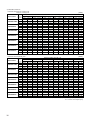
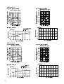
COOLING Capacity
Indoor
Indoor
intake air intake air
DB℃
WB℃
20
16
20
18
20
20
22
16
22
18
22
20
24
16
24
18
24
20
24
22
26
16
26
18
26
20
26
22
27
16
27
18
27
20
27
22
28
16
28
18
28
20
28
22
30
16
30
18
30
20
30
22
32
16
32
18
32
20
32
22
34
16
34
18
34
20
34
22
PEAD-RP2.5EA
CA
5940
6360
6840
5940
6360
6840
5940
6360
6840
7290
5940
6360
6840
7290
5940
6360
6840
7290
5940
6360
6840
7290
5940
6360
6840
7290
5940
6360
6840
7290
5940
6360
6840
7290
Capa
6000
20
SHC (W)
4099
3625
3078
4574
4134
3625
5049
4643
4172
3572
5524
5152
4720
4155
5762
5406
4993
4447
5940
5660
5267
4739
5940
6169
5814
5322
5940
6360
6361
5905
5940
6360
6840
6488
Input
1.86
SHF
0.69
0.57
0.45
0.77
0.65
0.53
0.85
0.73
0.61
0.49
0.93
0.81
0.69
0.57
0.97
0.85
0.73
0.61
1.00
0.89
0.77
0.65
1.00
0.97
0.85
0.73
1.00
1.00
0.93
0.81
1.00
1.00
1.00
0.89
SHF
0.79
PEAD-RP2.5EA / PUHZ-RP2.5VHA
P.C.
1.49
1.52
1.56
1.49
1.52
1.56
1.49
1.52
1.56
1.60
1.49
1.52
1.56
1.60
1.49
1.52
1.56
1.60
1.49
1.52
1.56
1.60
1.49
1.52
1.56
1.60
1.49
1.52
1.56
1.60
1.49
1.52
1.56
1.60
CA
5760
6180
6690
5760
6180
6690
5760
6180
6690
7140
5760
6180
6690
7140
5760
6180
6690
7140
5760
6180
6690
7140
5760
6180
6690
7140
5760
6180
6690
7140
5760
6180
6690
7140
25
SHC (W)
3974
3523
3011
4435
4017
3546
4896
4511
4081
3499
5357
5006
4616
4070
5587
5253
4884
4355
5760
5500
5151
4641
5760
5995
5687
5212
5760
6180
6222
5783
5760
6180
6690
6355
SHF
0.69
0.57
0.45
0.77
0.65
0.53
0.85
0.73
0.61
0.49
0.93
0.81
0.69
0.57
0.97
0.85
0.73
0.61
1.00
0.89
0.77
0.65
1.00
0.97
0.85
0.73
1.00
1.00
0.93
0.81
1.00
1.00
1.00
0.89
P.C.
1.57
1.60
1.64
1.57
1.60
1.64
1.57
1.60
1.64
1.69
1.57
1.60
1.64
1.69
1.57
1.60
1.64
1.69
1.57
1.60
1.64
1.69
1.57
1.60
1.64
1.69
1.57
1.60
1.64
1.69
1.57
1.60
1.64
1.69
CA
5580
5970
6510
5580
5970
6510
5580
5970
6510
6960
5580
5970
6510
6960
5580
5970
6510
6960
5580
5970
6510
6960
5580
5970
6510
6960
5580
5970
6510
6960
5580
5970
6510
6960
30
SHC (W)
3850
3403
2930
4297
3881
3450
4743
4358
3971
3410
5189
4836
4492
3967
5413
5075
4752
4246
5580
5313
5013
4524
5580
5791
5534
5081
5580
5970
6054
5638
5580
5970
6510
6194
SHF
0.69
0.57
0.45
0.77
0.65
0.53
0.85
0.73
0.61
0.49
0.93
0.81
0.69
0.57
0.97
0.85
0.73
0.61
1.00
0.89
0.77
0.65
1.00
0.97
0.85
0.73
1.00
1.00
0.93
0.81
1.00
1.00
1.00
0.89
P.C.
1.66
1.71
1.75
1.66
1.71
1.75
1.66
1.71
1.75
1.80
1.66
1.71
1.75
1.80
1.66
1.71
1.75
1.80
1.66
1.71
1.75
1.80
1.66
1.71
1.75
1.80
1.66
1.71
1.75
1.80
1.66
1.71
1.75
1.80
35
CA SHC (W)
5340
3685
5760
3283
6240
2808
5340
4112
5760
3744
6240
3307
5340
4539
5760
4205
6240
3806
6720
3293
5340
4966
5760
4666
6240
4306
6720
3830
5340
5180
5760
4896
6240
4555
6720
4099
5340
5340
5760
5126
6240
4805
6720
4368
5340
5340
5760
5587
6240
5304
6720
4906
5340
5340
5760
5760
6240
5803
6720
5443
5340
5340
5760
5760
6240
6240
6720
5981
Outdoor intake air DB℃
SHF
0.69
0.57
0.45
0.77
0.65
0.53
0.85
0.73
0.61
0.49
0.93
0.81
0.69
0.57
0.97
0.85
0.73
0.61
1.00
0.89
0.77
0.65
1.00
0.97
0.85
0.73
1.00
1.00
0.93
0.81
1.00
1.00
1.00
0.89
P.C.
1.79
1.83
1.88
1.79
1.83
1.88
1.79
1.83
1.88
1.92
1.79
1.83
1.88
1.92
1.79
1.83
1.88
1.92
1.79
1.83
1.88
1.92
1.79
1.83
1.88
1.92
1.79
1.83
1.88
1.92
1.79
1.83
1.88
1.92
SHF
0.69
0.57
0.45
0.77
0.65
0.53
0.85
0.73
0.61
0.49
0.93
0.81
0.69
0.57
0.97
0.85
0.73
0.61
1.00
0.89
0.77
0.65
1.00
0.97
0.85
0.73
1.00
1.00
0.93
0.81
1.00
1.00
1.00
0.89
P.C.
1.92
1.97
2.01
1.92
1.97
2.01
1.92
1.97
2.01
2.06
1.92
1.97
2.01
2.06
1.92
1.97
2.01
2.06
1.92
1.97
2.01
2.06
1.92
1.97
2.01
2.06
1.92
1.97
2.01
2.06
1.92
1.97
2.01
2.06
45
CA SHC (W)
4860
3353
5220
2975
5640
2538
4860
3742
5220
3393
5640
2989
4860
4131
5220
3811
5640
3440
6120
2999
4860
4520
5220
4228
5640
3892
6120
3488
4860
4714
5220
4437
5640
4117
6120
3733
4860
4860
5220
4646
5640
4343
6120
3978
4860
4860
5220
5063
5640
4794
6120
4468
4860
4860
5220
5220
5640
5245
6120
4957
4860
4860
5220
5220
5640
5640
6120
5447
SHF
0.69
0.57
0.45
0.77
0.65
0.53
0.85
0.73
0.61
0.49
0.93
0.81
0.69
0.57
0.97
0.85
0.73
0.61
1.00
0.89
0.77
0.65
1.00
0.97
0.85
0.73
1.00
1.00
0.93
0.81
1.00
1.00
1.00
0.89
PEAD2.5_cooling_matrixdata_INV_PEAD(E)041028.xls
40
CA SHC (W)
5100
3519
5580
3181
6000
2700
5100
3927
5580
3627
6000
3180
5100
4335
5580
4073
6000
3660
6480
3175
5100
4743
5580
4520
6000
4140
6480
3694
5100
4947
5580
4743
6000
4380
6480
3953
5100
5100
5580
4966
6000
4620
6480
4212
5100
5100
5580
5413
6000
5100
6480
4730
5100
5100
5580
5580
6000
5580
6480
5249
5100
5100
5580
5580
6000
6000
6480
5767
P.C.
2.07
2.12
2.16
2.07
2.12
2.16
2.07
2.12
2.16
2.19
2.07
2.12
2.16
2.19
2.07
2.12
2.16
2.19
2.07
2.12
2.16
2.19
2.07
2.12
2.16
2.19
2.07
2.12
2.16
2.19
2.07
2.12
2.16
2.19
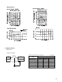
COOLING Capacity
Indoor
Indoor
intake air intake air
DB℃
WB℃
20
16
20
18
20
20
22
16
22
18
22
20
24
16
24
18
24
20
24
22
26
16
26
18
26
20
26
22
27
16
27
18
27
20
27
22
28
16
28
18
28
20
28
22
30
16
30
18
30
20
30
22
32
16
32
18
32
20
32
22
34
16
34
18
34
20
34
22
PEAD-RP3EA
CA
7029
7526
8094
7029
7526
8094
7029
7526
8094
8627
7029
7526
8094
8627
7029
7526
8094
8627
7029
7526
8094
8627
7029
7526
8094
8627
7029
7526
8094
8627
7029
7526
8094
8627
Capa
7100
20
SHC (W)
5131
4591
3966
5693
5193
4614
6256
5795
5261
4572
6818
6397
5909
5262
7029
6698
6232
5607
7029
6999
6556
5952
7029
7526
7204
6642
7029
7526
7851
7333
7029
7526
8094
8023
Input
2.15
PEAD-RP3EA / PUHZ-RP3VHA
SHF
0.73
0.61
0.49
0.81
0.69
0.57
0.89
0.77
0.65
0.53
0.97
0.85
0.73
0.61
1.00
0.89
0.77
0.65
1.00
0.93
0.81
0.69
1.00
1.00
0.89
0.77
1.00
1.00
0.97
0.85
1.00
1.00
1.00
0.93
SHF
0.83
P.C.
1.72
1.75
1.81
1.72
1.75
1.81
1.72
1.75
1.81
1.85
1.72
1.75
1.81
1.85
1.72
1.75
1.81
1.85
1.72
1.75
1.81
1.85
1.72
1.75
1.81
1.85
1.72
1.75
1.81
1.85
1.72
1.75
1.81
1.85
CA
6816
7313
7917
6816
7313
7917
6816
7313
7917
8449
6816
7313
7917
8449
6816
7313
7917
8449
6816
7313
7917
8449
6816
7313
7917
8449
6816
7313
7917
8449
6816
7313
7917
8449
25
SHC (W)
4976
4461
3879
5521
5046
4512
6066
5631
5146
4478
6612
6216
5779
5154
6816
6509
6096
5492
6816
6801
6412
5830
6816
7313
7046
6506
6816
7313
7679
7182
6816
7313
7917
7858
SHF
0.73
0.61
0.49
0.81
0.69
0.57
0.89
0.77
0.65
0.53
0.97
0.85
0.73
0.61
1.00
0.89
0.77
0.65
1.00
0.93
0.81
0.69
1.00
1.00
0.89
0.77
1.00
1.00
0.97
0.85
1.00
1.00
1.00
0.93
P.C.
1.82
1.85
1.89
1.82
1.85
1.89
1.82
1.85
1.89
1.96
1.82
1.85
1.89
1.96
1.82
1.85
1.89
1.96
1.82
1.85
1.89
1.96
1.82
1.85
1.89
1.96
1.82
1.85
1.89
1.96
1.82
1.85
1.89
1.96
CA
6603
7065
7704
6603
7065
7704
6603
7065
7704
8236
6603
7065
7704
8236
6603
7065
7704
8236
6603
7065
7704
8236
6603
7065
7704
8236
6603
7065
7704
8236
6603
7065
7704
8236
30
SHC (W)
4820
4309
3775
5348
4875
4391
5877
5440
5007
4365
6405
6005
5624
5024
6603
6287
5932
5353
6603
6570
6240
5683
6603
7065
6856
6342
6603
7065
7472
7001
6603
7065
7704
7659
SHF
0.73
0.61
0.49
0.81
0.69
0.57
0.89
0.77
0.65
0.53
0.97
0.85
0.73
0.61
1.00
0.89
0.77
0.65
1.00
0.93
0.81
0.69
1.00
1.00
0.89
0.77
1.00
1.00
0.97
0.85
1.00
1.00
1.00
0.93
P.C.
1.92
1.98
2.02
1.92
1.98
2.02
1.92
1.98
2.02
2.09
1.92
1.98
2.02
2.09
1.92
1.98
2.02
2.09
1.92
1.98
2.02
2.09
1.92
1.98
2.02
2.09
1.92
1.98
2.02
2.09
1.92
1.98
2.02
2.09
35
CA SHC (W)
6319
4613
6816
4158
7384
3618
6319
5118
6816
4703
7384
4209
6319
5624
6816
5248
7384
4800
7952
4215
6319
6129
6816
5794
7384
5390
7952
4851
6319
6319
6816
6066
7384
5686
7952
5169
6319
6319
6816
6339
7384
5981
7952
5487
6319
6319
6816
6816
7384
6572
7952
6123
6319
6319
6816
6816
7384
7162
7952
6759
6319
6319
6816
6816
7384
7384
7952
7395
Outdoor intake air DB℃
SHF
0.73
0.61
0.49
0.81
0.69
0.57
0.89
0.77
0.65
0.53
0.97
0.85
0.73
0.61
1.00
0.89
0.77
0.65
1.00
0.93
0.81
0.69
1.00
1.00
0.89
0.77
1.00
1.00
0.97
0.85
1.00
1.00
1.00
0.93
P.C.
2.06
2.12
2.17
2.06
2.12
2.17
2.06
2.12
2.17
2.21
2.06
2.12
2.17
2.21
2.06
2.12
2.17
2.21
2.06
2.12
2.17
2.21
2.06
2.12
2.17
2.21
2.06
2.12
2.17
2.21
2.06
2.12
2.17
2.21
SHF
0.73
0.61
0.49
0.81
0.69
0.57
0.89
0.77
0.65
0.53
0.97
0.85
0.73
0.61
1.00
0.89
0.77
0.65
1.00
0.93
0.81
0.69
1.00
1.00
0.89
0.77
1.00
1.00
0.97
0.85
1.00
1.00
1.00
0.93
P.C.
2.21
2.28
2.32
2.21
2.28
2.32
2.21
2.28
2.32
2.39
2.21
2.28
2.32
2.39
2.21
2.28
2.32
2.39
2.21
2.28
2.32
2.39
2.21
2.28
2.32
2.39
2.21
2.28
2.32
2.39
2.21
2.28
2.32
2.39
45
CA SHC (W)
5751
4198
6177
3768
6674
3270
5751
4658
6177
4262
6674
3804
5751
5118
6177
4756
6674
4338
7242
3838
5751
5578
6177
5250
6674
4872
7242
4418
5751
5751
6177
5498
6674
5139
7242
4707
5751
5751
6177
5745
6674
5406
7242
4997
5751
5751
6177
6177
6674
5940
7242
5576
5751
5751
6177
6177
6674
6474
7242
6156
5751
5751
6177
6177
6674
6674
7242
6735
SHF
0.73
0.61
0.49
0.81
0.69
0.57
0.89
0.77
0.65
0.53
0.97
0.85
0.73
0.61
1.00
0.89
0.77
0.65
1.00
0.93
0.81
0.69
1.00
1.00
0.89
0.77
1.00
1.00
0.97
0.85
1.00
1.00
1.00
0.93
PEAD3_cooling_matrixdata_INV_PEAD(E)041028.xls
40
CA SHC (W)
6035
4406
6603
4028
7100
3479
6035
4888
6603
4556
7100
4047
6035
5371
6603
5084
7100
4615
7668
4064
6035
5854
6603
5613
7100
5183
7668
4677
6035
6035
6603
5877
7100
5467
7668
4984
6035
6035
6603
6141
7100
5751
7668
5291
6035
6035
6603
6603
7100
6319
7668
5904
6035
6035
6603
6603
7100
6887
7668
6518
6035
6035
6603
6603
7100
7100
7668
7131
P.C.
2.40
2.45
2.49
2.40
2.45
2.49
2.40
2.45
2.49
2.54
2.40
2.45
2.49
2.54
2.40
2.45
2.49
2.54
2.40
2.45
2.49
2.54
2.40
2.45
2.49
2.54
2.40
2.45
2.49
2.54
2.40
2.45
2.49
2.54
COOLING Capacity
Indoor
Indoor
intake air intake air
DB℃
WB℃
20
16
20
18
20
20
22
16
22
18
22
20
24
16
24
18
24
20
24
22
26
16
26
18
26
20
26
22
27
16
27
18
27
20
27
22
28
16
28
18
28
20
28
22
30
16
30
18
30
20
30
22
32
16
32
18
32
20
32
22
34
16
34
18
34
20
34
22
PEAD-RP4EA
CA
9900
10600
11400
9900
10600
11400
9900
10600
11400
12150
9900
10600
11400
12150
9900
10600
11400
12150
9900
10600
11400
12150
9900
10600
11400
12150
9900
10600
11400
12150
9900
10600
11400
12150
Capa
10000
20
SHC (W)
7227
6466
5586
8019
7314
6498
8811
8162
7410
6440
9603
9010
8322
7412
9900
9434
8778
7898
9900
9858
9234
8384
9900
10600
10146
9356
9900
10600
11058
10328
9900
10600
11400
11300
Input
3.08
PEAD-RP4EA / PUHZ-RP4VHA
SHF
0.73
0.61
0.49
0.81
0.69
0.57
0.89
0.77
0.65
0.53
0.97
0.85
0.73
0.61
1.00
0.89
0.77
0.65
1.00
0.93
0.81
0.69
1.00
1.00
0.89
0.77
1.00
1.00
0.97
0.85
1.00
1.00
1.00
0.93
SHF
0.83
P.C.
2.46
2.51
2.59
2.46
2.51
2.59
2.46
2.51
2.59
2.65
2.46
2.51
2.59
2.65
2.46
2.51
2.59
2.65
2.46
2.51
2.59
2.65
2.46
2.51
2.59
2.65
2.46
2.51
2.59
2.65
2.46
2.51
2.59
2.65
CA
9600
10300
11150
9600
10300
11150
9600
10300
11150
11900
9600
10300
11150
11900
9600
10300
11150
11900
9600
10300
11150
11900
9600
10300
11150
11900
9600
10300
11150
11900
9600
10300
11150
11900
25
SHC (W)
7008
6283
5464
7776
7107
6356
8544
7931
7248
6307
9312
8755
8140
7259
9600
9167
8586
7735
9600
9579
9032
8211
9600
10300
9924
9163
9600
10300
10816
10115
9600
10300
11150
11067
SHF
0.73
0.61
0.49
0.81
0.69
0.57
0.89
0.77
0.65
0.53
0.97
0.85
0.73
0.61
1.00
0.89
0.77
0.65
1.00
0.93
0.81
0.69
1.00
1.00
0.89
0.77
1.00
1.00
0.97
0.85
1.00
1.00
1.00
0.93
P.C.
2.60
2.65
2.71
2.60
2.65
2.71
2.60
2.65
2.71
2.80
2.60
2.65
2.71
2.80
2.60
2.65
2.71
2.80
2.60
2.65
2.71
2.80
2.60
2.65
2.71
2.80
2.60
2.65
2.71
2.80
2.60
2.65
2.71
2.80
CA
9300
9950
10850
9300
9950
10850
9300
9950
10850
11600
9300
9950
10850
11600
9300
9950
10850
11600
9300
9950
10850
11600
9300
9950
10850
11600
9300
9950
10850
11600
9300
9950
10850
11600
30
SHC (W)
6789
6070
5317
7533
6866
6185
8277
7662
7053
6148
9021
8458
7921
7076
9300
8856
8355
7540
9300
9254
8789
8004
9300
9950
9657
8932
9300
9950
10525
9860
9300
9950
10850
10788
SHF
0.73
0.61
0.49
0.81
0.69
0.57
0.89
0.77
0.65
0.53
0.97
0.85
0.73
0.61
1.00
0.89
0.77
0.65
1.00
0.93
0.81
0.69
1.00
1.00
0.89
0.77
1.00
1.00
0.97
0.85
1.00
1.00
1.00
0.93
P.C.
2.76
2.83
2.90
2.76
2.83
2.90
2.76
2.83
2.90
2.99
2.76
2.83
2.90
2.99
2.76
2.83
2.90
2.99
2.76
2.83
2.90
2.99
2.76
2.83
2.90
2.99
2.76
2.83
2.90
2.99
2.76
2.83
2.90
2.99
35
CA SHC (W)
8900
6497
9600
5856
10400 5096
8900
7209
9600
6624
10400 5928
8900
7921
9600
7392
10400 6760
11200 5936
8900
8633
9600
8160
10400 7592
11200 6832
8900
8900
9600
8544
10400 8008
11200 7280
8900
8900
9600
8928
10400 8424
11200 7728
8900
8900
9600
9600
10400 9256
11200 8624
8900
8900
9600
9600
10400 10088
11200 9520
8900
8900
9600
9600
10400 10400
11200 10416
Outdoor intake air DB℃
SHF
0.73
0.61
0.49
0.81
0.69
0.57
0.89
0.77
0.65
0.53
0.97
0.85
0.73
0.61
1.00
0.89
0.77
0.65
1.00
0.93
0.81
0.69
1.00
1.00
0.89
0.77
1.00
1.00
0.97
0.85
1.00
1.00
1.00
0.93
P.C.
2.96
3.03
3.11
2.96
3.03
3.11
2.96
3.03
3.11
3.17
2.96
3.03
3.11
3.17
2.96
3.03
3.11
3.17
2.96
3.03
3.11
3.17
2.96
3.03
3.11
3.17
2.96
3.03
3.11
3.17
2.96
3.03
3.11
3.17
SHF
0.73
0.61
0.49
0.81
0.69
0.57
0.89
0.77
0.65
0.53
0.97
0.85
0.73
0.61
1.00
0.89
0.77
0.65
1.00
0.93
0.81
0.69
1.00
1.00
0.89
0.77
1.00
1.00
0.97
0.85
1.00
1.00
1.00
0.93
P.C.
3.17
3.26
3.33
3.17
3.26
3.33
3.17
3.26
3.33
3.42
3.17
3.26
3.33
3.42
3.17
3.26
3.33
3.42
3.17
3.26
3.33
3.42
3.17
3.26
3.33
3.42
3.17
3.26
3.33
3.42
3.17
3.26
3.33
3.42
45
CA SHC (W)
8100
5913
8700
5307
9400
4606
8100
6561
8700
6003
9400
5358
8100
7209
8700
6699
9400
6110
10200 5406
8100
7857
8700
7395
9400
6862
10200 6222
8100
8100
8700
7743
9400
7238
10200 6630
8100
8100
8700
8091
9400
7614
10200 7038
8100
8100
8700
8700
9400
8366
10200 7854
8100
8100
8700
8700
9400
9118
10200 8670
8100
8100
8700
8700
9400
9400
10200 9486
SHF
0.73
0.61
0.49
0.81
0.69
0.57
0.89
0.77
0.65
0.53
0.97
0.85
0.73
0.61
1.00
0.89
0.77
0.65
1.00
0.93
0.81
0.69
1.00
1.00
0.89
0.77
1.00
1.00
0.97
0.85
1.00
1.00
1.00
0.93
PEAD4_cooling_matrixdata_INV_PEAD(E)041028.xls
40
CA SHC (W)
8500
6205
9300
5673
10000 4900
8500
6885
9300
6417
10000 5700
8500
7565
9300
7161
10000 6500
10800 5724
8500
8245
9300
7905
10000 7300
10800 6588
8500
8500
9300
8277
10000 7700
10800 7020
8500
8500
9300
8649
10000 8100
10800 7452
8500
8500
9300
9300
10000 8900
10800 8316
8500
8500
9300
9300
10000 9700
10800 9180
8500
8500
9300
9300
10000 10000
10800 10044
P.C.
3.43
3.51
3.57
3.43
3.51
3.57
3.43
3.51
3.57
3.63
3.43
3.51
3.57
3.63
3.43
3.51
3.57
3.63
3.43
3.51
3.57
3.63
3.43
3.51
3.57
3.63
3.43
3.51
3.57
3.63
3.43
3.51
3.57
3.63
COOLING Capacity
Indoor
Indoor
intake air intake air
DB℃
WB℃
20
16
20
18
20
20
22
16
22
18
22
20
24
16
24
18
24
20
24
22
26
16
26
18
26
20
26
22
27
16
27
18
27
20
27
22
28
16
28
18
28
20
28
22
30
16
30
18
30
20
30
22
32
16
32
18
32
20
32
22
34
16
34
18
34
20
34
22
PEAD-RP5EA
CA
12375
13250
14250
12375
13250
14250
12375
13250
14250
15188
12375
13250
14250
15188
12375
13250
14250
15188
12375
13250
14250
15188
12375
13250
14250
15188
12375
13250
14250
15188
12375
13250
14250
15188
Capa
12500
20
SHC (W)
9034
8083
6983
10024
9143
8123
11014
10203
9263
8049
12004
11263
10403
9264
12375
11793
10973
9872
12375
12323
11543
10479
12375
13250
12683
11694
12375
13250
13823
12909
12375
13250
14250
14124
Input
3.69
PEAD-RP5EA / PUHZ-RP5VHA
SHF
0.73
0.61
0.49
0.81
0.69
0.57
0.89
0.77
0.65
0.53
0.97
0.85
0.73
0.61
1.00
0.89
0.77
0.65
1.00
0.93
0.81
0.69
1.00
1.00
0.89
0.77
1.00
1.00
0.97
0.85
1.00
1.00
1.00
0.93
SHF
0.83
P.C.
2.95
3.01
3.10
2.95
3.01
3.10
2.95
3.01
3.10
3.17
2.95
3.01
3.10
3.17
2.95
3.01
3.10
3.17
2.95
3.01
3.10
3.17
2.95
3.01
3.10
3.17
2.95
3.01
3.10
3.17
2.95
3.01
3.10
3.17
CA
12000
12875
13938
12000
12875
13938
12000
12875
13938
14875
12000
12875
13938
14875
12000
12875
13938
14875
12000
12875
13938
14875
12000
12875
13938
14875
12000
12875
13938
14875
12000
12875
13938
14875
25
SHC (W)
8760
7854
6829
9720
8884
7944
10680
9914
9059
7884
11640
10944
10174
9074
12000
11459
10732
9669
12000
11974
11289
10264
12000
12875
12404
11454
12000
12875
13519
12644
12000
12875
13938
13834
SHF
0.73
0.61
0.49
0.81
0.69
0.57
0.89
0.77
0.65
0.53
0.97
0.85
0.73
0.61
1.00
0.89
0.77
0.65
1.00
0.93
0.81
0.69
1.00
1.00
0.89
0.77
1.00
1.00
0.97
0.85
1.00
1.00
1.00
0.93
P.C.
3.12
3.17
3.25
3.12
3.17
3.25
3.12
3.17
3.25
3.36
3.12
3.17
3.25
3.36
3.12
3.17
3.25
3.36
3.12
3.17
3.25
3.36
3.12
3.17
3.25
3.36
3.12
3.17
3.25
3.36
3.12
3.17
3.25
3.36
CA
11625
12438
13563
11625
12438
13563
11625
12438
13563
14500
11625
12438
13563
14500
11625
12438
13563
14500
11625
12438
13563
14500
11625
12438
13563
14500
11625
12438
13563
14500
11625
12438
13563
14500
30
SHC (W)
8486
7587
6646
9416
8582
7731
10346
9577
8816
7685
11276
10572
9901
8845
11625
11069
10443
9425
11625
11567
10986
10005
11625
12438
12071
11165
11625
12438
13156
12325
11625
12438
13563
13485
SHF
0.73
0.61
0.49
0.81
0.69
0.57
0.89
0.77
0.65
0.53
0.97
0.85
0.73
0.61
1.00
0.89
0.77
0.65
1.00
0.93
0.81
0.69
1.00
1.00
0.89
0.77
1.00
1.00
0.97
0.85
1.00
1.00
1.00
0.93
P.C.
3.30
3.39
3.47
3.30
3.39
3.47
3.30
3.39
3.47
3.58
3.30
3.39
3.47
3.58
3.30
3.39
3.47
3.58
3.30
3.39
3.47
3.58
3.30
3.39
3.47
3.58
3.30
3.39
3.47
3.58
3.30
3.39
3.47
3.58
35
CA SHC (W)
11125 8121
12000 7320
13000 6370
11125 9011
12000 8280
13000 7410
11125 9901
12000 9240
13000 8450
14000 7420
11125 10791
12000 10200
13000 9490
14000 8540
11125 11125
12000 10680
13000 10010
14000 9100
11125 11125
12000 11160
13000 10530
14000 9660
11125 11125
12000 12000
13000 11570
14000 10780
11125 11125
12000 12000
13000 12610
14000 11900
11125 11125
12000 12000
13000 13000
14000 13020
Outdoor intake air DB℃
SHF
0.73
0.61
0.49
0.81
0.69
0.57
0.89
0.77
0.65
0.53
0.97
0.85
0.73
0.61
1.00
0.89
0.77
0.65
1.00
0.93
0.81
0.69
1.00
1.00
0.89
0.77
1.00
1.00
0.97
0.85
1.00
1.00
1.00
0.93
P.C.
3.54
3.63
3.73
3.54
3.63
3.73
3.54
3.63
3.73
3.80
3.54
3.63
3.73
3.80
3.54
3.63
3.73
3.80
3.54
3.63
3.73
3.80
3.54
3.63
3.73
3.80
3.54
3.63
3.73
3.80
3.54
3.63
3.73
3.80
SHF
0.73
0.61
0.49
0.81
0.69
0.57
0.89
0.77
0.65
0.53
0.97
0.85
0.73
0.61
1.00
0.89
0.77
0.65
1.00
0.93
0.81
0.69
1.00
1.00
0.89
0.77
1.00
1.00
0.97
0.85
1.00
1.00
1.00
0.93
P.C.
3.80
3.91
3.99
3.80
3.91
3.99
3.80
3.91
3.99
4.10
3.80
3.91
3.99
4.10
3.80
3.91
3.99
4.10
3.80
3.91
3.99
4.10
3.80
3.91
3.99
4.10
3.80
3.91
3.99
4.10
3.80
3.91
3.99
4.10
45
CA SHC (W)
10125 7391
10875 6634
11750 5758
10125 8201
10875 7504
11750 6698
10125 9011
10875 8374
11750 7638
12750 6758
10125 9821
10875 9244
11750 8578
12750 7778
10125 10125
10875 9679
11750 9048
12750 8288
10125 10125
10875 10114
11750 9518
12750 8798
10125 10125
10875 10875
11750 10458
12750 9818
10125 10125
10875 10875
11750 11398
12750 10838
10125 10125
10875 10875
11750 11750
12750 11858
SHF
0.73
0.61
0.49
0.81
0.69
0.57
0.89
0.77
0.65
0.53
0.97
0.85
0.73
0.61
1.00
0.89
0.77
0.65
1.00
0.93
0.81
0.69
1.00
1.00
0.89
0.77
1.00
1.00
0.97
0.85
1.00
1.00
1.00
0.93
PEAD5_cooling_matrixdata_INV_PEAD(E)041028.xls
40
CA SHC (W)
10625 7756
11625 7091
12500 6125
10625 8606
11625 8021
12500 7125
10625 9456
11625 8951
12500 8125
13500 7155
10625 10306
11625 9881
12500 9125
13500 8235
10625 10625
11625 10346
12500 9625
13500 8775
10625 10625
11625 10811
12500 10125
13500 9315
10625 10625
11625 11625
12500 11125
13500 10395
10625 10625
11625 11625
12500 12125
13500 11475
10625 10625
11625 11625
12500 12500
13500 12555
P.C.
4.11
4.21
4.28
4.11
4.21
4.28
4.11
4.21
4.28
4.35
4.11
4.21
4.28
4.35
4.11
4.21
4.28
4.35
4.11
4.21
4.28
4.35
4.11
4.21
4.28
4.35
4.11
4.21
4.28
4.35
4.11
4.21
4.28
4.35
COOLING Capacity
Indoor
Indoor
intake air intake air
DB℃
WB℃
20
16
20
18
20
20
22
16
22
18
22
20
24
16
24
18
24
20
24
22
26
16
26
18
26
20
26
22
27
16
27
18
27
20
27
22
28
16
28
18
28
20
28
22
30
16
30
18
30
20
30
22
32
16
32
18
32
20
32
22
34
16
34
18
34
20
34
22
PEAD-RP6EA
CA
13860
14840
15960
13860
14840
15960
13860
14840
15960
17010
13860
14840
15960
17010
13860
14840
15960
17010
13860
14840
15960
17010
13860
14840
15960
17010
13860
14840
15960
17010
13860
14840
15960
17010
Capa
14000
20
SHC (W)
9979
8904
7661
11088
10091
8938
12197
11278
10214
8845
13306
12466
11491
10206
13860
13059
12130
10886
13860
13653
12768
11567
13860
14840
14045
12928
13860
14840
15322
14288
13860
14840
15960
15649
Input
4.91
PEAD-RP6EA / PUHZ-RP6VHA
SHF
0.72
0.60
0.48
0.80
0.68
0.56
0.88
0.76
0.64
0.52
0.96
0.84
0.72
0.60
1.00
0.88
0.76
0.64
1.00
0.92
0.80
0.68
1.00
1.00
0.88
0.76
1.00
1.00
0.96
0.84
1.00
1.00
1.00
0.92
SHF
0.82
P.C.
3.93
4.00
4.12
3.93
4.00
4.12
3.93
4.00
4.12
4.22
3.93
4.00
4.12
4.22
3.93
4.00
4.12
4.22
3.93
4.00
4.12
4.22
3.93
4.00
4.12
4.22
3.93
4.00
4.12
4.22
3.93
4.00
4.12
4.22
CA
13440
14420
15610
13440
14420
15610
13440
14420
15610
16660
13440
14420
15610
16660
13440
14420
15610
16660
13440
14420
15610
16660
13440
14420
15610
16660
13440
14420
15610
16660
13440
14420
15610
16660
25
SHC (W)
9677
8652
7493
10752
9806
8742
11827
10959
9990
8663
12902
12113
11239
9996
13440
12690
11864
10662
13440
13266
12488
11329
13440
14420
13737
12662
13440
14420
14986
13994
13440
14420
15610
15327
SHF
0.72
0.60
0.48
0.80
0.68
0.56
0.88
0.76
0.64
0.52
0.96
0.84
0.72
0.60
1.00
0.88
0.76
0.64
1.00
0.92
0.80
0.68
1.00
1.00
0.88
0.76
1.00
1.00
0.96
0.84
1.00
1.00
1.00
0.92
P.C.
4.15
4.22
4.32
4.15
4.22
4.32
4.15
4.22
4.32
4.47
4.15
4.22
4.32
4.47
4.15
4.22
4.32
4.47
4.15
4.22
4.32
4.47
4.15
4.22
4.32
4.47
4.15
4.22
4.32
4.47
4.15
4.22
4.32
4.47
CA
13020
13930
15190
13020
13930
15190
13020
13930
15190
16240
13020
13930
15190
16240
13020
13930
15190
16240
13020
13930
15190
16240
13020
13930
15190
16240
13020
13930
15190
16240
13020
13930
15190
16240
30
SHC (W)
9374
8358
7291
10416
9472
8506
11458
10587
9722
8445
12499
11701
10937
9744
13020
12258
11544
10394
13020
12816
12152
11043
13020
13930
13367
12342
13020
13930
14582
13642
13020
13930
15190
14941
SHF
0.72
0.60
0.48
0.80
0.68
0.56
0.88
0.76
0.64
0.52
0.96
0.84
0.72
0.60
1.00
0.88
0.76
0.64
1.00
0.92
0.80
0.68
1.00
1.00
0.88
0.76
1.00
1.00
0.96
0.84
1.00
1.00
1.00
0.92
P.C.
4.39
4.52
4.62
4.39
4.52
4.62
4.39
4.52
4.62
4.76
4.39
4.52
4.62
4.76
4.39
4.52
4.62
4.76
4.39
4.52
4.62
4.76
4.39
4.52
4.62
4.76
4.39
4.52
4.62
4.76
4.39
4.52
4.62
4.76
35
CA SHC (W)
12460 8971
13440 8064
14560 6989
12460 9968
13440 9139
14560 8154
12460 10965
13440 10214
14560 9318
15680 8154
12460 11962
13440 11290
14560 10483
15680 9408
12460 12460
13440 11827
14560 11066
15680 10035
12460 12460
13440 12365
14560 11648
15680 10662
12460 12460
13440 13440
14560 12813
15680 11917
12460 12460
13440 13440
14560 13978
15680 13171
12460 12460
13440 13440
14560 14560
15680 14426
Outdoor intake air DB℃
SHF
0.72
0.60
0.48
0.80
0.68
0.56
0.88
0.76
0.64
0.52
0.96
0.84
0.72
0.60
1.00
0.88
0.76
0.64
1.00
0.92
0.80
0.68
1.00
1.00
0.88
0.76
1.00
1.00
0.96
0.84
1.00
1.00
1.00
0.92
P.C.
4.71
4.84
4.96
4.71
4.84
4.96
4.71
4.84
4.96
5.06
4.71
4.84
4.96
5.06
4.71
4.84
4.96
5.06
4.71
4.84
4.96
5.06
4.71
4.84
4.96
5.06
4.71
4.84
4.96
5.06
4.71
4.84
4.96
5.06
SHF
0.72
0.60
0.48
0.80
0.68
0.56
0.88
0.76
0.64
0.52
0.96
0.84
0.72
0.60
1.00
0.88
0.76
0.64
1.00
0.92
0.80
0.68
1.00
1.00
0.88
0.76
1.00
1.00
0.96
0.84
1.00
1.00
1.00
0.92
P.C.
5.06
5.20
5.30
5.06
5.20
5.30
5.06
5.20
5.30
5.45
5.06
5.20
5.30
5.45
5.06
5.20
5.30
5.45
5.06
5.20
5.30
5.45
5.06
5.20
5.30
5.45
5.06
5.20
5.30
5.45
5.06
5.20
5.30
5.45
45
CA SHC (W)
11340 8165
12180 7308
13160 6317
11340 9072
12180 8282
13160 7370
11340 9979
12180 9257
13160 8422
14280 7426
11340 10886
12180 10231
13160 9475
14280 8568
11340 11340
12180 10718
13160 10002
14280 9139
11340 11340
12180 11206
13160 10528
14280 9710
11340 11340
12180 12180
13160 11581
14280 10853
11340 11340
12180 12180
13160 12634
14280 11995
11340 11340
12180 12180
13160 13160
14280 13138
SHF
0.72
0.60
0.48
0.80
0.68
0.56
0.88
0.76
0.64
0.52
0.96
0.84
0.72
0.60
1.00
0.88
0.76
0.64
1.00
0.92
0.80
0.68
1.00
1.00
0.88
0.76
1.00
1.00
0.96
0.84
1.00
1.00
1.00
0.92
PEAD6_cooling_matrixdata_INV_PEAD(E)041028.xls
40
CA SHC (W)
11900 8568
13020 7812
14000 6720
11900 9520
13020 8854
14000 7840
11900 10472
13020 9895
14000 8960
15120 7862
11900 11424
13020 10937
14000 10080
15120 9072
11900 11900
13020 11458
14000 10640
15120 9677
11900 11900
13020 11978
14000 11200
15120 10282
11900 11900
13020 13020
14000 12320
15120 11491
11900 11900
13020 13020
14000 13440
15120 12701
11900 11900
13020 13020
14000 14000
15120 13910
P.C.
5.47
5.60
5.70
5.47
5.60
5.70
5.47
5.60
5.70
5.79
5.47
5.60
5.70
5.79
5.47
5.60
5.70
5.79
5.47
5.60
5.70
5.79
5.47
5.60
5.70
5.79
5.47
5.60
5.70
5.79
5.47
5.60
5.70
5.79
1) COOLING CAPACITY <2>
PEAD-RP1.6EA/PU(H)-P1.6VGAA(1).UK, PU(H)-P1.6YGAA(1).UK
Outdoor intake air D.B. (°C)
Indoor
Indoor
Intake air Intake air
20
25
D.B. (°C) W.B. (°C) CA SHC(W) SHF
P.C.
P.C.
CA SHC(W) SHF
2731
0.62
1.37
0.62
1.44
4272 2649
4406
16
20
2358
0.50
1.40
0.50
1.47
4584 2292
4717
18
20
1928
0.38
1.43
0.38
1.50
4962 1885
5073
3084
0.70
1.37
0.70
1.44
4272 2990
4406
16
22
2736
0.58
1.40
0.58
1.47
4584 2658
4717
18
2334
0.46
1.43
0.46
1.50
4962 2282
5073
20
3436
0.78
1.37
0.78
1.44
4272 3332
4406
16
3113
0.66
1.40
0.66
1.47
4584 3025
4717
18
24
2739
0.54
1.43
0.54
1.50
4962 2679
5073
20
2315
0.43
1.47
0.43
1.47
5296 2267
5407
22
16
3789
0.86
1.37
0.86
1.44
4272 3674
4406
3491
0.74
1.40
0.74
1.47
4584 3392
4717
18
26
3145
0.62
1.43
0.62
1.50
4962 3076
5073
20
2736
0.51
1.47
0.51
1.47
5296 2679
5407
22
4141
0.94
1.37
0.94
1.44
4272 4016
4406
16
3868
0.82
1.40
0.82
1.47
4584 3758
4717
18
28
3551
0.70
1.43
0.70
1.50
4962 3473
5073
20
3156
0.58
1.47
0.58
1.47
5296 3091
5407
22
4406
1.00
1.37
1.00
1.44
4272 4272
4406
16
4245
0.90
1.40
0.90
1.47
4584 4125
4717
18
30
3957
0.78
1.43
0.78
1.50
4962 3870
5073
20
3577
0.66
1.47
0.66
1.47
5296 3504
5407
22
4406
1.00
1.37
1.00
1.44
4272 4272
4406
16
4623
0.98
1.40
0.98
1.47
4584 4492
4717
18
32
4363
0.86
1.43
0.86
1.50
4962 4267
5073
20
3998
0.74
1.47
0.74
1.47
5296 3916
5407
22
4406
1.00
1.37
1.00
1.44
4272 4272
4406
16
4717
1.00
1.40
1.00
1.47
4584 4584
4717
18
34
4769
0.94
1.43
0.94
1.50
4962 4664
5073
20
4419
0.82
1.47
0.82
1.47
5296 4328
5407
22
Indoor
Indoor
Intake air Intake air
D.B. (°C) W.B. (°C)
16
20
18
20
16
22
18
20
16
18
24
20
22
16
18
26
20
22
16
18
28
20
22
16
18
30
20
22
16
18
32
20
22
16
18
34
20
22
22
CA
3961
4272
4628
3961
4272
4628
3961
4272
4628
4984
3961
4272
4628
4984
3961
4272
4628
4984
3961
4272
4628
4984
3961
4272
4628
4984
3961
4272
4628
4984
35
SHC(W)
2456
2136
1759
2772
2478
2129
3089
2820
2499
2134
3406
3161
2869
2522
3723
3503
3240
2910
3961
3845
3610
3297
3961
4187
3980
3685
3961
4272
4350
4073
SHF
0.62
0.50
0.38
0.70
0.58
0.46
0.78
0.66
0.54
0.43
0.86
0.74
0.62
0.51
0.94
0.82
0.70
0.58
1.00
0.90
0.78
0.66
1.00
0.98
0.86
0.74
1.00
1.00
0.94
0.82
Outdoor intake air D.B. (°C)
40
P.C.
CA SHC(W) SHF
P.C.
1.64
0.62
1.76
3783 2345
1.69
0.50
1.81
4139 2069
1.72
0.38
1.85
4450 1691
1.64
0.70
1.76
3783 2648
1.69
0.58
1.81
4139 2400
1.72
0.46
1.85
4450 2047
1.64
0.78
1.76
3783 2950
1.69
0.66
1.81
4139 2731
1.72
0.54
1.85
4450 2403
1.76
0.43
1.90
4806 2058
1.64
0.86
1.76
3783 3253
1.69
0.74
1.81
4139 3062
1.72
0.62
1.85
4450 2759
1.76
0.51
1.90
4806 2432
1.64
0.94
1.76
3783 3556
1.69
0.82
1.81
4139 3394
1.72
0.70
1.85
4450 3115
1.76
0.58
1.90
4806 2806
1.64
1.00
1.76
3783 3783
1.69
0.90
1.81
4139 3725
1.72
0.78
1.85
4450 3471
1.76
0.66
1.90
4806 3180
1.64
1.00
1.76
3783 3783
1.69
0.98
1.81
4139 4056
1.72
0.86
1.85
4450 3827
1.76
0.74
1.90
4806 3554
1.64
1.00
1.76
3783 3783
1.69
1.00
1.81
4139 4139
1.72
0.94
1.85
4450 4183
1.76
0.82
1.90
4806 3928
Notes CA: Capacity (W)
P.C.: Power consumption (kW)
(230V)
30
CA SHC(W)
2566
4139
2214
4428
1835
4828
2897
4139
2568
4428
2221
4828
3228
4139
2922
4428
2607
4828
2210
5162
3559
4139
3277
4428
2994
4828
2612
5162
3890
4139
3631
4428
3380
4828
3013
5162
4139
4139
3985
4428
3766
4828
3415
5162
4139
4139
4339
4428
4152
4828
3817
5162
4139
4139
4428
4428
4539
4828
4219
5162
SHF
0.62
0.50
0.38
0.70
0.58
0.46
0.78
0.66
0.54
0.43
0.86
0.74
0.62
0.51
0.94
0.82
0.70
0.58
1.00
0.90
0.78
0.66
1.00
0.98
0.86
0.74
1.00
1.00
0.94
0.82
P.C.
1.53
1.57
1.61
1.53
1.57
1.61
1.53
1.57
1.61
1.66
1.53
1.57
1.61
1.66
1.53
1.57
1.61
1.66
1.53
1.57
1.61
1.66
1.53
1.57
1.61
1.66
1.53
1.57
1.61
1.66
45
CA SHC(W) SHF
P.C.
0.62
1.91
2235
3605
0.50
1.95
1936
3872
0.38
1.99
1590
4183
0.70
1.91
2523
3605
0.58
1.95
2245
3872
0.46
1.99
1924
4183
0.78
1.91
2812
3605
0.66
1.95
2555
3872
0.54
1.99
2259
4183
0.43
2.02
1943
4539
0.86
1.91
3100
3605
0.74
1.95
2865
3872
0.62
1.99
2593
4183
0.51
2.02
2296
4539
0.94
1.91
3388
3605
0.82
1.95
3175
3872
0.70
1.99
2928
4183
0.58
2.02
2650
4539
1.00
1.91
3605
3605
0.90
1.95
3484
3872
0.78
1.99
3263
4183
0.66
2.02
3003
4539
1.00
1.91
3605
3605
0.98
1.95
3794
3872
0.86
1.99
3597
4183
0.74
2.02
3356
4539
1.00
1.91
3605
3605
1.00
1.95
3872
3872
0.94
1.99
3932
4183
0.82
2.02
3710
4539
SHC: Sensible heat capacity (W)
SHF: Sensible heat factor
PEAD-RP2EA/PU(H)-P2VGAA(1).UK, PU(H)-P2YGAA(1).UK
Outdoor intake air D.B. (°C)
Indoor
Indoor
Intake air Intake air
20
25
D.B. (°C) W.B. (°C) CA SHC(W) SHF
P.C.
P.C.
CA SHC(W) SHF
3533
0.64
2.02
0.64
2.14
5376 3426
5544
16
20
3050
0.51
2.06
0.51
2.17
5768 2964
5936
18
20
2493
0.39
2.12
0.39
2.22
6244 2439
6384
3989
0.72
2.02
0.72
2.14
5376 3868
5544
16
22
3538
0.60
2.06
0.60
2.17
5768 3438
5936
18
3018
0.47
2.12
0.47
2.22
6244 2952
6384
20
4444
0.80
2.02
0.80
2.14
5376 4310
5544
16
4027
0.68
2.06
0.68
2.17
5768 3913
5936
18
24
3543
0.56
2.12
0.56
2.22
6244 3465
6384
20
2994
0.44
2.18
0.44
2.18
6664 2932
6804
22
16
4900
0.88
2.02
0.88
2.14
5376 4752
5544
4515
0.76
2.06
0.76
2.17
5768 4387
5936
18
26
4068
0.64
2.12
0.64
2.22
6244 3979
6384
20
3538
0.52
2.18
0.52
2.18
6664 3465
6804
22
5356
0.97
2.02
0.97
2.14
5376 5194
5544
16
5003
0.84
2.06
0.84
2.17
5768 4861
5936
18
28
4593
0.72
2.12
0.72
2.22
6244 4492
6384
20
4082
0.60
2.18
0.60
2.18
6664 3998
6804
22
5544
1.00
2.02
1.00
2.14
5376 5376
5544
16
5491
0.93
2.06
0.93
2.17
5768 5335
5936
18
30
5118
0.80
2.12
0.80
2.22
6244 5006
6384
20
4627
0.68
2.18
0.68
2.18
6664 4531
6804
22
5544
1.00
2.02
1.00
2.14
5376 5376
5544
16
5936
1.00
2.06
1.00
2.17
5768 5768
5936
18
32
5643
0.88
2.12
0.88
2.22
6244 5519
6384
20
5171
0.76
2.18
0.76
2.18
6664 5065
6804
22
5544
1.00
2.02
1.00
2.14
5376 5376
5544
16
5936
1.00
2.06
1.00
2.17
5768 5768
5936
18
34
6168
0.97
2.12
0.97
2.22
6244 6032
6384
20
5715
0.84
2.18
0.84
2.18
6664 5598
6804
22
Indoor
Indoor
Intake air Intake air
D.B. (°C) W.B. (°C)
16
20
18
20
16
22
18
20
16
18
24
20
22
16
18
26
20
22
16
18
28
20
22
16
18
30
20
22
16
18
32
20
22
16
18
34
20
22
CA
4984
5376
5824
4984
5376
5824
4984
5376
5824
6272
4984
5376
5824
6272
4984
5376
5824
6272
4984
5376
5824
6272
4984
5376
5824
6272
4984
5376
5824
6272
35
SHC(W)
3176
2763
2275
3586
3205
2753
3995
3647
3232
2760
4405
4089
3711
3261
4815
4531
4190
3763
4984
4973
4669
4265
4984
5376
5148
4767
4984
5376
5627
5268
SHF
0.64
0.51
0.39
0.72
0.60
0.47
0.80
0.68
0.56
0.44
0.88
0.76
0.64
0.52
0.97
0.84
0.72
0.60
1.00
0.93
0.80
0.68
1.00
1.00
0.88
0.76
1.00
1.00
0.97
0.84
Outdoor intake air D.B. (°C)
40
P.C.
CA SHC(W) SHF
P.C.
2.43
0.64
2.60
4760 3033
2.49
0.51
2.68
5208 2676
2.55
0.39
2.73
5600 2187
2.43
0.72
2.60
4760 3425
2.49
0.60
2.68
5208 3105
2.55
0.47
2.73
5600 2648
2.43
0.80
2.60
4760 3816
2.49
0.68
2.68
5208 3533
2.55
0.56
2.73
5600 3108
2.61
0.44
2.81
6048 2661
2.43
0.88
2.60
4760 4207
2.49
0.76
2.68
5208 3961
2.55
0.64
2.73
5600 3568
2.61
0.52
2.81
6048 3145
2.43
0.97
2.60
4760 4599
2.49
0.84
2.68
5208 4389
2.55
0.72
2.73
5600 4029
2.61
0.60
2.81
6048 3629
2.43
1.00
2.60
4760 4760
2.49
0.93
2.68
5208 4817
2.55
0.80
2.73
5600 4489
2.61
0.68
2.81
6048 4113
2.43
1.00
2.60
4760 4760
2.49
1.00
2.68
5208 5208
2.55
0.88
2.73
5600 4950
2.61
0.76
2.81
6048 4596
2.43
1.00
2.60
4760 4760
2.49
1.00
2.68
5208 5208
2.55
0.97
2.73
5600 5410
2.61
0.84
2.81
6048 5080
Notes CA: Capacity (W)
P.C.: Power consumption (kW)
(230V)
30
CA SHC(W)
3319
5208
2863
5572
2373
6076
3747
5208
3322
5572
2873
6076
4175
5208
3780
5572
3372
6076
2858
6496
4603
5208
4238
5572
3872
6076
3378
6496
5032
5208
4696
5572
4371
6076
3898
6496
5208
5208
5154
5572
4871
6076
4417
6496
5208
5208
5572
5572
5370
6076
4937
6496
5208
5208
5572
5572
5870
6076
5457
6496
SHF
0.64
0.51
0.39
0.72
0.60
0.47
0.80
0.68
0.56
0.44
0.88
0.76
0.64
0.52
0.97
0.84
0.72
0.60
1.00
0.93
0.80
0.68
1.00
1.00
0.88
0.76
1.00
1.00
0.97
0.84
P.C.
2.26
2.33
2.38
2.26
2.33
2.38
2.26
2.33
2.38
2.45
2.26
2.33
2.38
2.45
2.26
2.33
2.38
2.45
2.26
2.33
2.38
2.45
2.26
2.33
2.38
2.45
2.26
2.33
2.38
2.45
45
CA SHC(W) SHF
P.C.
0.64
2.82
2890
4536
0.51
2.89
2504
4872
0.39
2.94
2056
5264
0.72
2.82
3263
4536
0.60
2.89
2904
4872
0.47
2.94
2489
5264
0.80
2.82
3636
4536
0.68
2.89
3305
4872
0.56
2.94
2922
5264
0.44
2.98
2513
5712
0.88
2.82
4009
4536
0.76
2.89
3705
4872
0.64
2.94
3354
5264
0.52
2.98
2970
5712
0.97
2.82
4382
4536
0.84
2.89
4106
4872
0.72
2.94
3787
5264
0.60
2.98
3427
5712
1.00
2.82
4536
4536
0.93
2.89
4507
4872
0.80
2.94
4220
5264
0.68
2.98
3884
5712
1.00
2.82
4536
4536
1.00
2.89
4872
4872
0.88
2.94
4653
5264
0.76
2.98
4341
5712
1.00
2.82
4536
4536
1.00
2.89
4872
4872
0.97
2.94
5086
5264
0.84
2.98
4798
5712
SHC: Sensible heat capacity (W)
SHF: Sensible heat factor
23
PEAD-RP2.5EA/PU(H)-P2.5VGAA(1).UK, PU(H)-P2.5YGAA(1).UK
Outdoor intake air D.B. (°C)
Indoor
Indoor
Intake air Intake air
20
25
D.B. (°C) W.B. (°C) CA SHC(W) SHF
P.C.
P.C.
CA SHC(W) SHF
3995
0.61
2.12
0.61
2.24
6336 3874
6534
16
20
3449
0.49
2.16
0.49
2.28
6798 3352
6996
18
20
2819
0.37
2.22
0.37
2.33
7359 2758
7524
4510
0.69
2.12
0.69
2.24
6336 4374
6534
16
22
4001
0.57
2.16
0.57
2.28
6798 3888
6996
18
3413
0.45
2.22
0.45
2.33
7359 3338
7524
20
5026
0.77
2.12
0.77
2.24
6336 4873
6534
16
4553
0.65
2.16
0.65
2.28
6798 4424
6996
18
24
4007
0.53
2.22
0.53
2.33
7359 3919
7524
20
3385
0.42
2.28
0.42
2.28
7854 3316
8019
22
16
5541
0.85
2.12
0.85
2.24
6336 5373
6534
5105
0.73
2.16
0.73
2.28
6798 4961
6996
18
26
4600
0.61
2.22
0.61
2.33
7359 4499
7524
20
4001
0.50
2.28
0.50
2.28
7854 3918
8019
22
6057
0.93
2.12
0.93
2.24
6336 5873
6534
16
5657
0.81
2.16
0.81
2.28
6798 5497
6996
18
28
5194
0.69
2.22
0.69
2.33
7359 5080
7524
20
4616
0.58
2.28
0.58
2.28
7854 4521
8019
22
6443
0.99
2.12
0.99
2.24
6336 6248
6534
16
6209
0.89
2.16
0.89
2.28
6798 6033
6996
18
30
5787
0.77
2.22
0.77
2.33
7359 5660
7524
20
5232
0.65
2.28
0.65
2.28
7854 5124
8019
22
6534
1.00
2.12
1.00
2.24
6336 6336
6534
16
6761
0.97
2.16
0.97
2.28
6798 6570
6996
18
32
6381
0.85
2.22
0.85
2.33
7359 6241
7524
20
5847
0.73
2.28
0.73
2.28
7854 5727
8019
22
6534
1.00
2.12
1.00
2.24
6336 6336
6534
16
6996
1.00
2.16
1.00
2.28
6798 6798
6996
18
34
6974
0.93
2.22
0.93
2.33
7359 6821
7524
20
6463
0.81
2.28
0.81
2.28
7854 6330
8019
22
Indoor
Indoor
Intake air Intake air
D.B. (°C) W.B. (°C)
16
20
18
20
16
22
18
20
16
18
24
20
22
16
18
26
20
22
16
18
28
20
22
16
18
30
20
22
16
18
32
20
22
16
18
34
20
22
24
CA
5874
6336
6864
5874
6336
6864
5874
6336
6864
7392
5874
6336
6864
7392
5874
6336
6864
7392
5874
6336
6864
7392
5874
6336
6864
7392
5874
6336
6864
7392
35
SHC(W)
3591
3124
2572
4055
3624
3114
4518
4124
3655
3121
4981
4624
4197
3688
5445
5123
4738
4255
5792
5623
5280
4823
5874
6123
5821
5390
5874
6336
6363
5958
SHF
0.61
0.49
0.37
0.69
0.57
0.45
0.77
0.65
0.53
0.42
0.85
0.73
0.61
0.50
0.93
0.81
0.69
0.58
0.99
0.89
0.77
0.65
1.00
0.97
0.85
0.73
1.00
1.00
0.93
0.81
Outdoor intake air D.B. (°C)
40
P.C.
CA SHC(W) SHF
P.C.
2.54
0.61
2.73
5610 3430
2.61
0.49
2.81
6138 3026
2.67
0.37
2.86
6600 2473
2.54
0.69
2.73
5610 3872
2.61
0.57
2.81
6138 3511
2.67
0.45
2.86
6600 2994
2.54
0.77
2.73
5610 4315
2.61
0.65
2.81
6138 3995
2.67
0.53
2.86
6600 3515
2.73
0.42
2.94
7128 3009
2.54
0.85
2.73
5610 4758
2.61
0.73
2.81
6138 4479
2.67
0.61
2.86
6600 4035
2.73
0.50
2.94
7128 3556
2.54
0.93
2.73
5610 5200
2.61
0.81
2.81
6138 4963
2.67
0.69
2.86
6600 4556
2.73
0.58
2.94
7128 4103
2.54
0.99
2.73
5610 5532
2.61
0.89
2.81
6138 5447
2.67
0.77
2.86
6600 5076
2.73
0.65
2.94
7128 4650
2.54
1.00
2.73
5610 5610
2.61
0.97
2.81
6138 5932
2.67
0.85
2.86
6600 5597
2.73
0.73
2.94
7128 5198
2.54
1.00
2.73
5610 5610
2.61
1.00
2.81
6138 6138
2.67
0.93
2.86
6600 6118
2.73
0.81
2.94
7128 5745
Notes CA: Capacity (W)
P.C.: Power consumption (kW)
(230V)
30
CA SHC(W)
3753
6138
3238
6567
2683
7161
4237
6138
3756
6567
3248
7161
4721
6138
4274
6567
3813
7161
3232
7656
5205
6138
4792
6567
4378
7161
3820
7656
5690
6138
5310
6567
4943
7161
4407
7656
6053
6138
5828
6567
5508
7161
4995
7656
6138
6138
6346
6567
6073
7161
5583
7656
6138
6138
6567
6567
6638
7161
6170
7656
SHF
0.61
0.49
0.37
0.69
0.57
0.45
0.77
0.65
0.53
0.42
0.85
0.73
0.61
0.50
0.93
0.81
0.69
0.58
0.99
0.89
0.77
0.65
1.00
0.97
0.85
0.73
1.00
1.00
0.93
0.81
P.C.
2.37
2.44
2.49
2.37
2.44
2.49
2.37
2.44
2.49
2.57
2.37
2.44
2.49
2.57
2.37
2.44
2.49
2.57
2.37
2.44
2.49
2.57
2.37
2.44
2.49
2.57
2.37
2.44
2.49
2.57
45
CA SHC(W) SHF
P.C.
0.61
2.95
3268
5346
0.49
3.02
2831
5742
0.37
3.08
2325
6204
0.69
2.95
3690
5346
0.57
3.02
3284
5742
0.45
3.08
2814
6204
0.77
2.95
4112
5346
0.65
3.02
3737
5742
0.53
3.08
3304
6204
0.42
3.13
2842
6732
0.85
2.95
4534
5346
0.73
3.02
4190
5742
0.61
3.08
3793
6204
0.50
3.13
3359
6732
0.93
2.95
4955
5346
0.81
3.02
4643
5742
0.69
3.08
4282
6204
0.58
3.13
3875
6732
0.99
2.95
5272
5346
0.89
3.02
5096
5742
0.77
3.08
4772
6204
0.65
3.13
4392
6732
1.00
2.95
5346
5346
0.97
3.02
5549
5742
0.85
3.08
5261
6204
0.73
3.13
4909
6732
1.00
2.95
5346
5346
1.00
3.02
5742
5742
0.93
3.08
5751
6204
0.81
3.13
5426
6732
SHC: Sensible heat capacity (W)
SHF: Sensible heat factor
PEAD-RP3EA1/PU(H)-P3VGAA(1).UK, PU(H)-P3YGAA(1).UK
Outdoor intake air D.B. (°C)
Indoor
Indoor
Intake air Intake air
20
25
D.B. (°C) W.B. (°C) CA SHC(W) SHF
P.C.
P.C.
CA SHC(W) SHF
5054
0.67
2.68
0.67
2.83
7296 4900
7524
16
20
4364
0.54
2.73
0.54
2.88
7828 4240
8056
18
20
3567
0.41
2.81
0.41
2.95
8474 3488
8664
5706
0.76
2.68
0.76
2.83
7296 5533
7524
16
22
5062
0.63
2.73
0.63
2.88
7828 4919
8056
18
4317
0.50
2.81
0.50
2.95
8474 4223
8664
20
6358
0.84
2.68
0.84
2.83
7296 6165
7524
16
5760
0.71
2.73
0.71
2.88
7828 5597
8056
18
24
5068
0.59
2.81
0.59
2.95
8474 4957
8664
20
4283
0.46
2.88
0.46
2.88
9044 4194
9234
22
16
7010
0.93
2.68
0.93
2.83
7296 6797
7524
6458
0.80
2.73
0.80
2.88
7828 6275
8056
18
26
5819
0.67
2.81
0.67
2.95
8474 5692
8664
20
5061
0.55
2.88
0.55
2.88
9044 4957
9234
22
7524
1.00
2.68
1.00
2.83
7296 7296
7524
16
7156
0.89
2.73
0.89
2.88
7828 6954
8056
18
28
6570
0.76
2.81
0.76
2.95
8474 6426
8664
20
5840
0.63
2.88
0.63
2.88
9044 5720
9234
22
7524
1.00
2.68
1.00
2.83
7296 7296
7524
16
7855
0.98
2.73
0.98
2.88
7828 7632
8056
18
30
7321
0.84
2.81
0.84
2.95
8474 7161
8664
20
6618
0.72
2.88
0.72
2.88
9044 6482
9234
22
7524
1.00
2.68
1.00
2.83
7296 7296
7524
16
8056
1.00
2.73
1.00
2.88
7828 7828
8056
18
32
8072
0.93
2.81
0.93
2.95
8474 7895
8664
20
7397
0.80
2.88
0.80
2.88
9044 7245
9234
22
7524
1.00
2.68
1.00
2.83
7296 7296
7524
16
8056
1.00
2.73
1.00
2.88
7828 7828
8056
18
34
8664
1.00
2.81
1.00
2.95
8474 8474
8664
20
8176
0.89
2.88
0.89
2.88
9044 8008
9234
22
Indoor
Indoor
Intake air Intake air
D.B. (°C) W.B. (°C)
16
20
18
20
16
22
18
20
16
18
24
20
22
16
18
26
20
22
16
18
28
20
22
16
18
30
20
22
16
18
32
20
22
16
18
34
20
22
CA
6764
7296
7904
6764
7296
7904
6764
7296
7904
8512
6764
7296
7904
8512
6764
7296
7904
8512
6764
7296
7904
8512
6764
7296
7904
8512
6764
7296
7904
8512
35
SHC(W)
4543
3952
3254
5129
4584
3939
5716
5217
4624
3948
6302
5849
5309
4665
6764
6481
5994
5383
6764
7114
6679
6101
6764
7296
7364
6819
6764
7296
7904
7537
SHF
0.67
0.54
0.41
0.76
0.63
0.50
0.84
0.71
0.59
0.46
0.93
0.80
0.67
0.55
1.00
0.89
0.76
0.63
1.00
0.98
0.84
0.72
1.00
1.00
0.93
0.80
1.00
1.00
1.00
0.89
Outdoor intake air D.B. (°C)
40
P.C.
CA SHC(W) SHF
P.C.
3.22
0.67
3.45
6460 4339
3.30
0.54
3.55
7068 3828
3.38
0.41
3.62
7600 3129
3.22
0.76
3.45
6460 4899
3.30
0.63
3.55
7068 4441
3.38
0.50
3.62
7600 3787
3.22
0.84
3.45
6460 5459
3.30
0.71
3.55
7068 5054
3.38
0.59
3.62
7600 4446
3.45
0.46
3.72
8208 3807
3.22
0.93
3.45
6460 6019
3.30
0.80
3.55
7068 5666
3.38
0.67
3.62
7600 5105
3.45
0.55
3.72
8208 4499
3.22
1.00
3.45
6460 6460
3.30
0.89
3.55
7068 6279
3.38
0.76
3.62
7600 5763
3.45
0.63
3.72
8208 5191
3.22
1.00
3.45
6460 6460
3.30
0.98
3.55
7068 6891
3.38
0.84
3.62
7600 6422
3.45
0.72
3.72
8208 5883
3.22
1.00
3.45
6460 6460
3.30
1.00
3.55
7068 7068
3.38
0.93
3.62
7600 7081
3.45
0.80
3.72
8208 6575
3.22
1.00
3.45
6460 6460
3.30
1.00
3.55
7068 7068
3.38
1.00
3.62
7600 7600
3.45
0.89
3.72
8208 7267
Notes CA: Capacity (W)
P.C.: Power consumption (kW)
(230V)
30
CA SHC(W)
4747
7068
4096
7562
3395
8246
5360
7068
4751
7562
4109
8246
5972
7068
5407
7562
4824
8246
4089
8816
6585
7068
6062
7562
5539
8246
4832
8816
7068
7068
6718
7562
6253
8246
5575
8816
7068
7068
7373
7562
6968
8246
6319
8816
7068
7068
7562
7562
7682
8246
7062
8816
7068
7068
7562
7562
8246
8246
7806
8816
SHF
0.67
0.54
0.41
0.76
0.63
0.50
0.84
0.71
0.59
0.46
0.93
0.80
0.67
0.55
1.00
0.89
0.76
0.63
1.00
0.98
0.84
0.72
1.00
1.00
0.93
0.80
1.00
1.00
1.00
0.89
P.C.
2.99
3.08
3.15
2.99
3.08
3.15
2.99
3.08
3.15
3.25
2.99
3.08
3.15
3.25
2.99
3.08
3.15
3.25
2.99
3.08
3.15
3.25
2.99
3.08
3.15
3.25
2.99
3.08
3.15
3.25
45
CA SHC(W) SHF
P.C.
0.67
3.74
4135
6156
0.54
3.82
3581
6612
0.41
3.89
2941
7144
0.76
3.74
4668
6156
0.63
3.82
4155
6612
0.50
3.89
3560
7144
0.84
3.74
5202
6156
0.71
3.82
4728
6612
0.59
3.89
4179
7144
0.46
3.95
3595
7752
0.93
3.74
5735
6156
0.80
3.82
5301
6612
0.67
3.89
4798
7144
0.55
3.95
4249
7752
1.00
3.74
6156
6156
0.89
3.82
5874
6612
0.76
3.89
5418
7144
0.63
3.95
4903
7752
1.00
3.74
6156
6156
0.98
3.82
6447
6612
0.84
3.89
6037
7144
0.72
3.95
5556
7752
1.00
3.74
6156
6156
1.00
3.82
6612
6612
0.93
3.89
6656
7144
0.80
3.95
6210
7752
1.00
3.74
6156
6156
1.00
3.82
6612
6612
1.00
3.89
7144
7144
0.89
3.95
6864
7752
SHC: Sensible heat capacity (W)
SHF: Sensible heat factor
25
PEAD-RP4EA1/PU(H)-P4VGAA(1).UK, PU(H)-P4YGAA(1).UK
Outdoor intake air D.B. (°C)
Indoor
Indoor
Intake air Intake air
20
25
D.B. (°C) W.B. (°C) CA SHC(W) SHF
P.C.
P.C.
CA SHC(W) SHF
6138
0.65
3.06
0.65
3.24
9216 5952
9504
16
20
0.52
3.13
0.52
3.29
9888 5150
10176 5300
18
20
0.40
3.21
0.40
3.37
10704 4237
10944 4332
6930
0.73
3.06
0.73
3.24
9216 6720
9504
16
22
0.60
3.13
0.60
3.29
9888 5974
10176 6148
18
0.48
3.21
0.48
3.37
10704 5129
10944 5244
20
7722
0.81
3.06
0.81
3.24
9216 7488
9504
16
0.69
3.13
0.69
3.29
9888 6798
10176 6996
18
24
0.56
3.21
0.56
3.37
10704 6021
10944 6156
20
0.45
3.30
0.45
3.30
11424 5095
11664 5202
22
16
8514
0.90
3.06
0.90
3.24
9216 8256
9504
0.77
3.13
0.77
3.29
9888 7622
10176 7844
18
26
0.65
3.21
0.65
3.37
10704 6913
10944 7068
20
0.53
3.30
0.53
3.30
11424 6021
11664 6147
22
9306
0.98
3.06
0.98
3.24
9216 9024
9504
16
0.85
3.13
0.85
3.29
9888 8446
10176 8692
18
28
0.73
3.21
0.73
3.37
10704 7805
10944 7980
20
0.61
3.30
0.61
3.30
11424 6947
11664 7093
22
9504
1.00
3.06
1.00
3.24
9216 9216
9504
16
0.94
3.13
0.94
3.29
9888 9270
10176 9540
18
30
0.81
3.21
0.81
3.37
10704 8697
10944 8892
20
0.69
3.30
0.69
3.30
11424 7873
11664 8039
22
9504
1.00
3.06
1.00
3.24
9216 9216
9504
16
3.13
1.00
3.29
9888 9888
10176 10176 1.00
18
32
0.90
3.21
0.90
3.37
10704 9589
10944 9804
20
0.77
3.30
0.77
3.30
11424 8799
11664 8984
22
9504
1.00
3.06
1.00
3.24
9216 9216
9504
16
3.13
1.00
3.29
9888 9888
10176 10176 1.00
18
34
3.21
0.98
3.37
10704 10481
10944 10716 0.98
20
0.85
3.30
0.85
3.30
11424 9726
11664 9930
22
Indoor
Indoor
Intake air Intake air
D.B. (°C) W.B. (°C)
16
20
18
20
16
22
18
20
16
18
24
20
22
16
18
26
20
22
16
18
28
20
22
16
18
30
20
22
16
18
32
20
22
16
18
34
20
22
26
CA
8544
9216
9984
8544
9216
9984
8544
9216
9984
10752
8544
9216
9984
10752
8544
9216
9984
10752
8544
9216
9984
10752
8544
9216
9984
10752
8544
9216
9984
10752
35
SHC(W)
5518
4800
3952
6230
5568
4784
6942
6336
5616
4795
7654
7104
6448
5667
8366
7872
7280
6538
8544
8640
8112
7410
8544
9216
8944
8282
8544
9216
9776
9154
SHF
0.65
0.52
0.40
0.73
0.60
0.48
0.81
0.69
0.56
0.45
0.90
0.77
0.65
0.53
0.98
0.85
0.73
0.61
1.00
0.94
0.81
0.69
1.00
1.00
0.90
0.77
1.00
1.00
0.98
0.85
Outdoor intake air D.B. (°C)
40
P.C.
CA SHC(W) SHF
P.C.
3.68
0.65
3.94
8160 5270
3.77
0.52
4.06
8928 4650
3.86
0.40
4.14
9600 3800
3.68
0.73
3.94
8160 5950
3.77
0.60
4.06
8928 5394
3.86
0.48
4.14
9600 4600
3.68
0.81
3.94
8160 6630
3.77
0.69
4.06
8928 6138
3.86
0.56
4.14
9600 5400
3.95
0.45
4.26
10368 4624
3.68
0.90
3.94
8160 7310
3.77
0.77
4.06
8928 6882
3.86
0.65
4.14
9600 6200
3.95
0.53
4.26
10368 5464
3.68
0.98
3.94
8160 7990
3.77
0.85
4.06
8928 7626
3.86
0.73
4.14
9600 7000
3.95
0.61
4.26
10368 6305
3.68
1.00
3.94
8160 8160
3.77
0.94
4.06
8928 8370
3.86
0.81
4.14
9600 7800
3.95
0.69
4.26
10368 7145
3.68
1.00
3.94
8160 8160
3.77
1.00
4.06
8928 8928
3.86
0.90
4.14
9600 8600
3.95
0.77
4.26
10368 7986
3.68
1.00
3.94
8160 8160
3.77
1.00
4.06
8928 8928
3.86
0.98
4.14
9600 9400
3.95
0.85
4.26
10368 8827
Notes CA: Capacity (W)
P.C.: Power consumption (kW)
(230V)
30
CA SHC(W)
5766
8928
4975
9552
10416 4123
6510
8928
5771
9552
10416 4991
7254
8928
6567
9552
10416 5859
11136 4966
7998
8928
7363
9552
10416 6727
11136 5869
8742
8928
8159
9552
10416 7595
11136 6772
8928
8928
8955
9552
10416 8463
11136 7675
8928
8928
9552
9552
10416 9331
11136 8578
8928
8928
9552
9552
10416 10199
11136 9481
SHF
0.65
0.52
0.40
0.73
0.60
0.48
0.81
0.69
0.56
0.45
0.90
0.77
0.65
0.53
0.98
0.85
0.73
0.61
1.00
0.94
0.81
0.69
1.00
1.00
0.90
0.77
1.00
1.00
0.98
0.85
P.C.
3.42
3.52
3.60
3.42
3.52
3.60
3.42
3.52
3.60
3.71
3.42
3.52
3.60
3.71
3.42
3.52
3.60
3.71
3.42
3.52
3.60
3.71
3.42
3.52
3.60
3.71
3.42
3.52
3.60
3.71
45
CA SHC(W) SHF
P.C.
0.65
4.27
5022
7776
0.52
4.37
4350
8352
0.40
4.45
3572
9024
0.73
4.27
5670
7776
0.60
4.37
5046
8352
0.48
4.45
4324
9024
0.81
4.27
6318
7776
0.69
4.37
5742
8352
0.56
4.45
5076
9024
0.45
4.52
4367
9792
0.90
4.27
6966
7776
0.77
4.37
6438
8352
0.65
4.45
5828
9024
0.53
4.52
5161
9792
0.98
4.27
7614
7776
0.85
4.37
7134
8352
0.73
4.45
6580
9024
0.61
4.52
5955
9792
1.00
4.27
7776
7776
0.94
4.37
7830
8352
0.81
4.45
7332
9024
0.69
4.52
6748
9792
1.00
4.27
7776
7776
1.00
4.37
8352
8352
0.90
4.45
8084
9024
0.77
4.52
7542
9792
1.00
4.27
7776
7776
1.00
4.37
8352
8352
0.98
4.45
8836
9024
0.85
4.52
8336
9792
SHC: Sensible heat capacity (W)
SHF: Sensible heat factor
PEAD-RP5EA1/PU(H)-P5VGAA(1).UK, PU(H)-P5YGAA(1).UK
Outdoor intake air D.B. (°C)
Indoor
Indoor
Intake air Intake air
20
25
D.B. (°C) W.B. (°C) CA SHC(W) SHF
P.C.
P.C.
CA SHC(W) SHF
0.64
3.89
0.64
4.11
11712 7463
12078 7696
16
20
0.51
3.97
0.51
4.18
12566 6457
12932 6646
18
20
0.39
4.09
0.39
4.28
13603 5313
13908 5432
0.72
3.89
0.72
4.11
11712 8426
12078 8689
16
22
0.60
3.97
0.60
4.18
12566 7491
12932 7709
18
0.47
4.09
0.47
4.28
13603 6431
13908 6575
20
0.80
3.89
0.80
4.11
11712 9389
12078 9683
16
0.68
3.97
0.68
4.18
12566 8524
12932 8772
18
24
0.56
4.09
0.56
4.28
13603 7550
13908 7719
20
0.44
4.19
0.44
4.19
14518 6388
14823 6522
22
16
3.89
0.88
4.11
11712 10352
12078 10676 0.88
0.76
3.97
0.76
4.18
12566 9557
12932 9836
18
26
0.64
4.09
0.64
4.28
13603 8668
13908 8862
20
0.52
4.19
0.52
4.19
14518 7549
14823 7708
22
3.89
0.97
4.11
11712 11315
12078 11669 0.97
16
3.97
0.84
4.18
12566 10590
12932 10899 0.84
18
28
4.09
0.72
4.28
13603 9787
13908 10006 0.72
20
0.60
4.19
0.60
4.19
14518 8711
14823 8894
22
3.89
1.00
4.11
11712 11712
12078 12078 1.00
16
3.97
0.93
4.18
12566 11624
12932 11962 0.93
18
30
4.09
0.80
4.28
13603 10905
13908 11150 0.80
20
4.19
0.68
4.19
14518 9872
14823 10079 0.68
22
3.89
1.00
4.11
11712 11712
12078 12078 1.00
16
3.97
1.00
4.18
12566 12566
12932 12932 1.00
18
32
4.09
0.88
4.28
13603 12023
13908 12293 0.88
20
4.19
0.76
4.19
14518 11033
14823 11265 0.76
22
3.89
1.00
4.11
11712 11712
12078 12078 1.00
16
3.97
1.00
4.18
12566 12566
12932 12932 1.00
18
34
4.09
0.97
4.28
13603 13142
13908 13437 0.97
20
4.19
0.84
4.19
14518 12195
14823 12451 0.84
22
Indoor
Indoor
Intake air Intake air
D.B. (°C) W.B. (°C)
16
20
18
20
16
22
18
20
16
18
24
20
22
16
18
26
20
22
16
18
28
20
22
16
18
30
20
22
16
18
32
20
22
16
18
34
20
22
CA
10858
11712
12688
10858
11712
12688
10858
11712
12688
13664
10858
11712
12688
13664
10858
11712
12688
13664
10858
11712
12688
13664
10858
11712
12688
13664
10858
11712
12688
13664
35
SHC(W)
6919
6019
4955
7812
6982
5999
8704
7945
7042
6012
9597
8908
8085
7105
10490
9871
9128
8198
10858
10834
10172
9291
10858
11712
11215
10384
10858
11712
12258
11478
SHF
0.64
0.51
0.39
0.72
0.60
0.47
0.80
0.68
0.56
0.44
0.88
0.76
0.64
0.52
0.97
0.84
0.72
0.60
1.00
0.93
0.80
0.68
1.00
1.00
0.88
0.76
1.00
1.00
0.97
0.84
Outdoor intake air D.B. (°C)
40
P.C.
CA SHC(W) SHF
P.C.
4.67
0.64
5.01
10370 6608
4.80
0.51
5.16
11346 5831
4.91
0.39
5.26
12200 4765
4.67
0.72
5.01
10370 7461
4.80
0.60
5.16
11346 6763
4.91
0.47
5.26
12200 5768
4.67
0.80
5.01
10370 8313
4.80
0.68
5.16
11346 7696
4.91
0.56
5.26
12200 6771
5.02
0.44
5.41
13176 5797
4.67
0.88
5.01
10370 9166
4.80
0.76
5.16
11346 8629
4.91
0.64
5.26
12200 7774
5.02
0.52
5.41
13176 6851
4.67
0.97
5.01
10370 10019
4.80
0.84
5.16
11346 9562
4.91
0.72
5.26
12200 8777
5.02
0.60
5.41
13176 7905
4.67
1.00
5.01
10370 10370
4.80
0.93
5.16
11346 10495
4.91
0.80
5.26
12200 9780
5.02
0.68
5.41
13176 8959
4.67
1.00
5.01
10370 10370
4.80
1.00
5.16
11346 11346
4.91
0.88
5.26
12200 10783
5.02
0.76
5.41
13176 10013
4.67
1.00
5.01
10370 10370
4.80
1.00
5.16
11346 11346
4.91
0.97
5.26
12200 11787
5.02
0.84
5.41
13176 11068
Notes CA: Capacity (W)
P.C.: Power consumption (kW)
(230V)
30
CA SHC(W)
11346 7230
12139 6238
13237 5170
11346 8163
12139 7236
13237 6258
11346 9096
12139 8234
13237 7347
14152 6227
11346 10029
12139 9232
13237 8435
14152 7359
11346 10961
12139 10230
13237 9523
14152 8491
11346 11346
12139 11229
13237 10612
14152 9623
11346 11346
12139 12139
13237 11700
14152 10755
11346 11346
12139 12139
13237 12788
14152 11888
SHF
0.64
0.51
0.39
0.72
0.60
0.47
0.80
0.68
0.56
0.44
0.88
0.76
0.64
0.52
0.97
0.84
0.72
0.60
1.00
0.93
0.80
0.68
1.00
1.00
0.88
0.76
1.00
1.00
0.97
0.84
P.C.
4.35
4.48
4.58
4.35
4.48
4.58
4.35
4.48
4.58
4.72
4.35
4.48
4.58
4.72
4.35
4.48
4.58
4.72
4.35
4.48
4.58
4.72
4.35
4.48
4.58
4.72
4.35
4.48
4.58
4.72
45
CA SHC(W) SHF
P.C.
0.64
5.43
6297
9882
0.51
5.56
10614 5454
0.39
5.65
11468 4479
0.72
5.43
7110
9882
0.60
5.56
10614 6327
0.47
5.65
11468 5422
0.80
5.43
7922
9882
0.68
5.56
10614 7200
0.56
5.65
11468 6365
0.44
5.74
12444 5475
0.88
5.43
8735
9882
0.76
5.56
10614 8073
0.64
5.65
11468 7308
0.52
5.74
12444 6471
0.97
5.43
9547
9882
0.84
5.56
10614 8945
0.72
5.65
11468 8251
0.60
5.74
12444 7466
1.00
5.43
9882
9882
0.93
5.56
10614 9818
0.80
5.65
11468 9193
0.68
5.74
12444 8462
1.00
5.43
9882
9882
5.56
10614 10614 1.00
5.65
11468 10136 0.88
0.76
5.74
12444 9457
1.00
5.43
9882
9882
5.56
10614 10614 1.00
5.65
11468 11079 0.97
5.74
12444 10453 0.84
SHC: Sensible heat capacity (W)
SHF: Sensible heat factor
27
PEAD-RP6EA1/PU(H)-P6VGAA(1).UK, PU(H)-P6YGAA(1).UK
Outdoor intake air D.B. (°C)
Indoor
Indoor
Intake air Intake air
20
25
D.B. (°C) W.B. (°C) CA SHC(W) SHF
P.C.
P.C.
CA SHC(W) SHF
0.64
4.64
0.64
4.91
13440 8564
13860 8832
16
20
0.51
4.74
0.51
4.99
14420 7410
14840 7626
18
20
0.39
4.88
0.39
5.11
15610 6097
15960 6233
0.72
4.64
0.72
4.91
13440 9669
13860 9971
16
22
0.60
4.74
0.60
4.99
14420 8596
14840 8846
18
0.47
4.88
0.47
5.11
15610 7380
15960 7545
20
4.64
0.80
4.91
13440 10774
13860 11111 0.80
16
4.74
0.68
4.99
14420 9782
14840 10066 0.68
18
24
0.56
4.88
0.56
5.11
15610 8664
15960 8858
20
0.44
5.00
0.44
5.00
16660 7330
17010 7484
22
16
4.64
0.88
4.91
13440 11879
13860 12251 0.88
4.74
0.76
4.99
14420 10967
14840 11287 0.76
18
26
4.88
0.64
5.11
15610 9947
15960 10170 0.64
20
0.52
5.00
0.52
5.00
16660 8663
17010 8845
22
4.64
0.97
4.91
13440 12985
13860 13390 0.97
16
4.74
0.84
4.99
14420 12153
14840 12507 0.84
18
28
4.88
0.72
5.11
15610 11231
15960 11482 0.72
20
5.00
0.60
5.00
16660 9996
17010 10206 0.60
22
4.64
1.00
4.91
13440 13440
13860 13860 1.00
16
4.74
0.93
4.99
14420 13339
14840 13727 0.93
18
30
4.88
0.80
5.11
15610 12514
15960 12795 0.80
20
5.00
0.68
5.00
16660 11329
17010 11567 0.68
22
4.64
1.00
4.91
13440 13440
13860 13860 1.00
16
4.74
1.00
4.99
14420 14420
14840 14840 1.00
18
32
4.88
0.88
5.11
15610 13797
15960 14107 0.88
20
5.00
0.76
5.00
16660 12661
17010 12927 0.76
22
4.64
1.00
4.91
13440 13440
13860 13860 1.00
16
4.74
1.00
4.99
14420 14420
14840 14840 1.00
18
34
4.88
0.97
5.11
15610 15081
15960 15419 0.97
20
5.00
0.84
5.00
16660 13994
17010 14288 0.84
22
Indoor
Indoor
Intake air Intake air
D.B. (°C) W.B. (°C)
16
20
18
20
16
22
18
20
16
18
24
20
22
16
18
26
20
22
16
18
28
20
22
16
18
30
20
22
16
18
32
20
22
16
18
34
20
22
28
CA
12460
13440
14560
12460
13440
14560
12460
13440
14560
15680
12460
13440
14560
15680
12460
13440
14560
15680
12460
13440
14560
15680
12460
13440
14560
15680
12460
13440
14560
15680
35
SHC(W)
7940
6907
5686
8964
8012
6884
9989
9117
8081
6899
11013
10222
9278
8154
12038
11327
10475
9408
12460
12432
11672
10662
12460
13440
12869
11916
12460
13440
14067
13171
SHF
0.64
0.51
0.39
0.72
0.60
0.47
0.80
0.68
0.56
0.44
0.88
0.76
0.64
0.52
0.97
0.84
0.72
0.60
1.00
0.93
0.80
0.68
1.00
1.00
0.88
0.76
1.00
1.00
0.97
0.84
Outdoor intake air D.B. (°C)
40
P.C.
CA SHC(W) SHF
P.C.
5.58
0.64
5.98
11900 7583
5.73
0.51
6.16
13020 6691
5.86
0.39
6.28
14000 5468
5.58
0.72
5.98
11900 8561
5.73
0.60
6.16
13020 7761
5.86
0.47
6.28
14000 6619
5.58
0.80
5.98
11900 9540
5.73
0.68
6.16
13020 8832
5.86
0.56
6.28
14000 7770
5.99
0.44
6.46
15120 6653
5.58
0.88
5.98
11900 10518
5.73
0.76
6.16
13020 9902
5.86
0.64
6.28
14000 8921
5.99
0.52
6.46
15120 7862
5.58
0.97
5.98
11900 11497
5.73
0.84
6.16
13020 10973
5.86
0.72
6.28
14000 10072
5.99
0.60
6.46
15120 9072
5.58
1.00
5.98
11900 11900
5.73
0.93
6.16
13020 12044
5.86
0.80
6.28
14000 11223
5.99
0.68
6.46
15120 10281
5.58
1.00
5.98
11900 11900
5.73
1.00
6.16
13020 13020
5.86
0.88
6.28
14000 12374
5.99
0.76
6.46
15120 11491
5.58
1.00
5.98
11900 11900
5.73
1.00
6.16
13020 13020
5.86
0.97
6.28
14000 13526
5.99
0.84
6.46
15120 12701
Notes CA: Capacity (W)
P.C.: Power consumption (kW)
(230V)
30
CA SHC(W)
13020 8297
13930 7158
15190 5933
13020 9367
13930 8304
15190 7181
13020 10438
13930 9449
15190 8430
16240 7146
13020 11508
13930 10595
15190 9679
16240 8445
13020 12579
13930 11740
15190 10928
16240 9744
13020 13020
13930 12885
15190 12177
16240 11043
13020 13020
13930 13930
15190 13426
16240 12342
13020 13020
13930 13930
15190 14675
16240 13642
SHF
0.64
0.51
0.39
0.72
0.60
0.47
0.80
0.68
0.56
0.44
0.88
0.76
0.64
0.52
0.97
0.84
0.72
0.60
1.00
0.93
0.80
0.68
1.00
1.00
0.88
0.76
1.00
1.00
0.97
0.84
P.C.
5.19
5.34
5.46
5.19
5.34
5.46
5.19
5.34
5.46
5.63
5.19
5.34
5.46
5.63
5.19
5.34
5.46
5.63
5.19
5.34
5.46
5.63
5.19
5.34
5.46
5.63
5.19
5.34
5.46
5.63
45
CA SHC(W) SHF
P.C.
0.64
6.48
11340 7226
0.51
6.63
12180 6259
0.39
6.74
13160 5140
0.72
6.48
11340 8158
0.60
6.63
12180 7261
0.47
6.74
13160 6222
0.80
6.48
11340 9091
0.68
6.63
12180 8262
0.56
6.74
13160 7304
0.44
6.85
14280 6283
6.48
11340 10023 0.88
0.76
6.63
12180 9264
0.64
6.74
13160 8386
0.52
6.85
14280 7426
6.48
11340 10956 0.97
6.63
12180 10265 0.84
0.72
6.74
13160 9468
0.60
6.85
14280 8568
6.48
11340 11340 1.00
6.63
12180 11267 0.93
6.74
13160 10550 0.80
0.68
6.85
14280 9710
6.48
11340 11340 1.00
6.63
12180 12180 1.00
6.74
13160 11632 0.88
6.85
14280 10853 0.76
6.48
11340 11340 1.00
6.63
12180 12180 1.00
6.74
13160 12714 0.97
6.85
14280 11995 0.84
SHC: Sensible heat capacity (W)
SHF: Sensible heat factor
Cooling capacity correction factors
PEAD-RP·EA/PUHZ-RP·VHA
Service Ref.
PEAD-RP1.6EA
PEAD-RP2EA
PEAD-RP2.5EA
PEAD-RP3EA1
PEAD-RP4EA1
PEAD-RP5EA1
PEAD-RP6EA1
5m
1.00
1.00
1.00
1.00
1.00
1.00
1.00
10m
0.992
0.985
0.992
0.989
0.985
0.982
0.976
15m
0.984
0.971
0.984
0.978
0.971
0.963
0.953
20m
0.977
0.958
0.977
0.967
0.958
0.947
0.932
25m
0.969
0.943
0.969
0.956
0.943
0.930
0.912
Refrigerant piping length (one way)
30m 35m 40m 45m 50m 55m
0.962 0.956 0.949 0.942 0.937
0.931 0.919 0.908 0.898 0.887
0.962 0.956 0.949 0.942 0.937
0.947 0.938 0.930 0.913 0.905
0.931 0.919 0.908 0.898 0.887 0.876
0.914 0.900 0.885 0.871 0.858 0.845
0.893 0.876 0.858 0.842 0.828 0.813
60m
65m
70m
75m
80m
0.865 0.855 0.847 0.838
0.834 0.823 0.812 0.802
0.800 0.788 0.776 0.764
CAPACITY (RATIO)
1.4
1.2
INDOOR W.B.(°C)
1.0
22
20
18
16
0.8
TOTAL INPUT (RATIO)
INDOOR W.B.(°C)
22
20
18
16
1.2
1.0
0.8
0.6
0.4
-5
0
10
20
30
40
46
OUTDOOR D.B.(°C)
PEAD-RP·EA / PUH-P·VGAA.UK
PU-P·VGAA.UK
PUH-P·VGAA1.UK
PU-P·VGAA1.UK
10m
0.993
0.993
0.989
0.981
0.989
0.981
0.975
Refrigerant piping length (one way)
20m
25m
30m
35m
0.978
0.969
0.961
0.956
0.978
0.969
0.961
0.956
0.940
0.950
0.960
0.970
0.913
0.925
0.940
0.952
0.940
0.950
0.960
0.970
0.952
0.940
0.925
0.913
0.935
0.918
0.900
0.884
15m
0.984
0.984
0.980
0.968
0.980
0.968
0.955
40m
0.948
0.948
0.930
0.900
0.930
0.900
0.869
45m
50m
0.920
0.886
0.920
0.886
0.855
0.910
0.874
0.910
0.874
0.840
1.4
CAPACITY (RATIO)
PEAD-RP1.6EA
PEAD-RP2EA
PEAD-RP2.5EA
PEAD-RP3EA1
PEAD-RP4EA1
PEAD-RP5EA1
PEAD-RP6EA1
5m
1.00
1.00
1.00
1.00
1.00
1.00
1.00
1.2
INDOOR W.B.(°C)
1.0
22
20
18
16
0.8
INDOOR W.B.(°C)
TOTAL INPUT (RATIO)
Service Ref.
PUH-P·YGAA.UK
PU-P·YGAA.UK
PUH-P·YGAA1.UK
PU-P·YGAA1.UK
22
20
18
16
1.2
1.0
0.8
0.6
0.4
-5
0
10
20
30
40
46
OUTDOOR D.B.(°C)
29
2) HEATING CAPACITY
PEAD-RP·EA / PU(H)-P·VGAA(1).UK
PU(H)-P·YGAA(1).UK
Indoor
-10
Service Ref. Intake air
D.B.(°C)
CA
3080
15
2959
20
PEAD-RP1.6EA
2862
25
4001
15
3843
20
PEAD-RP2EA
3717
25
4540
15
4362
20
PEAD-RP2.5EA
4219
25
5747
15
5521
20
PEAD-RP3EA1
5340
25
6541
15
6283
20
PEAD-RP4EA1
6077
25
8890
15
8540
20
PEAD-RP5EA1
8260
25
10541
15
10126
20
PEAD-RP6EA1
9794
25
(230V)
Outdoor Intake air W.B. (°C)
0
5
-5
P.C.
1.02
1.11
1.18
1.30
1.41
1.50
1.39
1.51
1.61
1.87
2.03
2.16
2.33
2.52
2.69
2.79
3.03
3.23
3.48
3.77
4.01
P.C.
1.12
1.21
1.31
1.43
1.54
1.67
1.53
1.65
1.79
2.07
2.23
2.42
2.57
2.76
3.00
3.08
3.32
3.60
3.84
4.13
4.48
CA
3347
3201
3104
4347
4158
4032
4934
4719
4576
6245
5973
5792
7107
6798
6592
9660
9240
8960
11454
10956
10624
CA
3735
3541
3395
4851
4599
4410
5506
5220
5005
6969
6607
6335
7931
7519
7210
10780
10220
9800
12782
12118
11620
P.C.
1.30
1.40
1.52
1.65
1.78
1.94
1.77
1.91
2.08
2.39
2.58
2.80
2.96
3.19
3.46
3.56
3.84
4.17
4.43
4.78
5.19
CA
4899
4729
4462
6363
6143
5796
7222
6971
6578
9141
8824
8326
10403
10043
9476
14140
13650
12880
16766
16185
15272
10
P.C.
1.56
1.68
1.78
1.98
2.13
2.27
2.12
2.29
2.43
2.86
3.08
3.28
3.55
3.82
4.06
4.27
4.60
4.88
5.31
5.72
6.08
CA
5529
5335
5141
7182
6930
6678
8151
7865
7579
10317
9955
9593
11742
11330
10918
15960
15400
14840
18924
18260
17596
15
P.C.
1.73
1.87
2.00
2.20
2.38
2.54
2.36
2.55
2.73
3.18
3.43
3.67
3.94
4.25
4.55
4.74
5.12
5.47
5.90
6.37
6.81
CA
6160
5941
5723
8001
7718
7434
9081
8759
8437
11494
11086
10679
13081
12618
12154
17780
17150
16520
21082
20335
19588
PEAD-RP·EA / PUHZ-RP·VHA
Indoor
-10
Service Ref. Intake air
D.B.(°C)
CA
2604
15
2501
20
PEAD-RP1.6EA
2419
25
3810
15
3660
20
PEAD-RP2EA
3540
25
4445
15
4270
20
PEAD-RP2.5EA
4130
25
5080
15
4880
20
PEAD-RP3EA1
4720
25
7112
15
6832
20
PEAD-RP4EA1
6608
25
8890
15
8540
20
PEAD-RP5EA1
8260
25
10160
15
9760
20
PEAD-RP6EA1
9440
25
P.C.
1.87
2.01
2.15
2.38
2.55
2.74
2.55
2.74
2.94
3.43
3.69
3.96
4.25
4.57
4.91
5.12
5.50
5.90
6.37
6.84
7.35
(230V)
Outdoor Intake air W.B. (°C)
0
5
-5
P.C.
0.74
0.81
0.86
0.97
1.06
1.12
1.12
1.22
1.29
1.38
1.50
1.59
2.05
2.23
2.37
2.42
2.63
2.79
2.81
3.05
3.24
CA
2829
2706
2624
4140
3960
3840
4830
4620
4480
5520
5280
5120
7728
7392
7168
9660
9240
8960
11040
10560
10240
P.C.
0.82
0.88
0.96
1.07
1.16
1.25
1.24
1.33
1.44
1.52
1.64
1.78
2.26
2.44
2.64
2.67
2.88
3.12
3.09
3.33
3.62
CA
3157
2993
2870
4620
4380
4200
5390
5110
4900
6160
5840
5600
8624
8176
7840
10780
10220
9800
12320
11680
11200
P.C.
0.95
1.02
1.11
1.24
1.34
1.45
1.43
1.54
1.67
1.76
1.90
2.06
2.61
2.82
3.06
3.08
3.33
3.62
3.57
3.86
4.19
CA
4141
3998
3772
6060
5850
5520
7070
6825
6440
8080
7800
7360
11312
10920
10304
14140
13650
12880
16160
15600
14720
10
P.C.
1.13
1.22
1.30
1.49
1.60
1.70
1.71
1.84
1.96
2.11
2.27
2.41
3.13
3.38
3.58
3.70
3.99
4.23
4.28
4.62
4.90
CA
4674
4510
4346
6840
6600
6360
7980
7700
7420
9120
8800
8480
12768
12320
11872
15960
15400
14840
18240
17600
16960
15
P.C.
1.26
1.36
1.46
1.65
1.78
1.91
1.90
2.05
2.19
2.34
2.53
2.70
3.48
3.76
4.02
4.11
4.44
4.75
4.76
5.14
5.50
CA
5207
5023
4838
7620
7350
7080
8890
8575
8260
10160
9800
9440
14224
13720
13216
17780
17150
16520
20320
19600
18880
P.C.
1.36
1.46
1.57
1.78
1.91
2.05
2.05
2.20
2.37
2.53
2.71
2.91
3.76
4.04
4.33
4.44
4.77
5.12
5.14
5.52
5.93
Notes CA: Capacity (W)
P.C.: Power consumption (kW)
30
Heating capacity correction factor
PEAD-RP·EA/PUHZ-RP·VHA
Service Ref.
PEAD-RP1.6EA
PEAD-RP2EA
PEAD-RP2.5EA
PEAD-RP3EA1
PEAD-RP4EA1
PEAD-RP5EA1
PEAD-RP6EA1
5m
1.00
1.00
1.00
1.00
1.00
1.00
1.00
10m
0.997
0.997
0.997
0.997
0.997
0.997
0.997
15m
0.994
0.994
0.994
0.994
0.994
0.994
0.994
20m
0.991
0.991
0.991
0.991
0.991
0.991
0.991
25m
0.988
0.988
0.988
0.988
0.988
0.988
0.988
Refrigerant piping length (one way)
30m 35m 40m 45m 50m 55m
0.985 0.982 0.979 0.976 0.973
0.985 0.982 0.979 0.976 0.973
0.985 0.982 0.979 0.976 0.973
0.985 0.982 0.979 0.976 0.973
0.985 0.982 0.979 0.976 0.973 0.970
0.985 0.982 0.979 0.976 0.973 0.970
0.985 0.982 0.979 0.976 0.973 0.970
60m
65m
70m
75m
80m
0.967 0.964 0.961 0.958
0.967 0.964 0.961 0.958
0.967 0.964 0.961 0.958
Correcting the capacity line influenced by frosting
Not correcting the capacity line influenced by frosting
CAPACITY (RATIO)
1.4
1.2
In some cases, heating operation
cannot be conducted with the maximum
frequency in the area below the slanting line.
15
20
25
In some cases, heating operation
cannot be conducted with the maximum
frequency in the area below the slanting line.
25
20
INDOOR D.B.(°C)
1.0
0.8
0.6
0.4
TOTAL INPUT (RATIO)
1.4
1.2
INDOOR D.B.(°C)
15
1.0
0.8
0.6
0.4
-12 -10
-5
0
5
10
15
OUTDOOR W.B.(°C)
PEAD-RP·EA / PUH-P·VGAA.UK
PU-P·VGAA.UK
PUH-P·VGAA1.UK
PU-P·VGAA1.UK
10m
0.998
0.998
0.998
0.998
0.998
0.998
0.998
Refrigerant piping length (one way)
20m
25m
30m
35m
0.993
0.990
0.988
0.985
0.993
0.990
0.988
0.985
0.993
0.990
0.988
0.985
0.993
0.990
0.988
0.985
0.993
0.990
0.988
0.985
0.993
0.990
0.988
0.985
0.993
0.990
0.988
0.985
15m
0.995
0.995
0.995
0.995
0.995
0.995
0.995
40m
0.983
0.983
0.983
0.983
0.983
0.983
0.983
45m
50m
0.980
0.980
0.980
0.980
0.980
0.978
0.978
0.978
0.978
0.978
Correcting the capacity line influenced by frosting
Not correcting the capacity line influenced by frosting
1.4
CAPACITY (RATIO)
PEAD-RP1.6EA
PEAD-RP2EA
PEAD-RP2.5EA
PEAD-RP3EA1
PEAD-RP4EA1
PEAD-RP5EA1
PEAD-RP6EA1
5m
1.00
1.00
1.00
1.00
1.00
1.00
1.00
15
20
25
1.2
INDOOR D.B.(°C)
1.0
0.8
0.6
0.4
1.4
TOTAL INPUT (RATIO)
Service Ref.
PUH-P·YGAA.UK
PU-P·YGAA.UK
PUH-P·YGAA1.UK
PU-P·YGAA1.UK
25
20
1.2
INDOOR D.B.(°C)
15
1.0
0.8
0.6
0.4
-12 -10
-5
0
5
10
15
OUTDOOR W.B.(°C)
31
2 . FAN PERFORMANCE AND CORRECTED AIR FLOW
PEAD-RP1.6EA
80
60
40
20
6
External static pressure (Pa)
(1Pa 0.1mmAq)
140
8 10 12 14 16
Air Flow (CMM)
Fan Performance <70Pa>
120
100
80
60
40
1.0
0.9
0.8
10 12 14 16 18
Air flow (CMM)
Heating
1.1
1.0
0.9
20
8
10 12 14 16 18
Air flow (CMM)
8 10 12 14 16 18
Air Flow (CMM)
Corrected Air Flow
120
Correction factor
100
80
60
40
20
External static pressure (Pa)
(1Pa 0.1mmAq)
160
8
100
80
60
40
0.8
8
10 12 14 16 18 20 22
Air Flow (CMM)
10 12 14 16 18 20
Air flow (CMM)
22
Heating
1.2
1.1
1.0
0.9
0.8
20
32
Cooling
0.9
1.3
120
Capacity
input
1.0
Fan Performance <70Pa>
140
8
1.1
10 12 14 16 18 20
Air Flow (CMM)
Correction factor
External static pressure (Pa)
(1Pa 0.1mmAq)
PEAD-RP2EA
140 Fan Performance <30Pa>
6
20
1.2
0.8
6
Capacity
input
Cooling
1.1
1.3
Correction factor
External static pressure (Pa)
(1Pa 0.1mmAq)
Fan Performance <30Pa>
100
Correction factor
Corrected Air Flow
8
10 12 14 16 18 20
Air flow (CMM)
22
Fan Performance <30Pa>
120
100
80
60
40
20
8
120
100
80
60
1.1
40
Cooling
1.0
0.9
0.8
12 14 16 18 20 22 24 26
Air flow (CMM)
1.3
Correction factor
External static pressure (Pa)
(1Pa 0.1mmAq)
10 12 14 16 18 20 22 24
Air Flow (CMM)
Fan Performance <70Pa>
140
Capacity
input
Corrected Air Flow
Correction factor
External static pressure (Pa)
(1Pa 0.1mmAq)
PEAD-RP2.5EA
Heating
1.2
1.1
1.0
0.9
0.8
12 14 16 18 20 22 24 26
Air flow (CMM)
20
10 12 14 16 18 20 22 24 26
Air Flow (CMM)
PEAD-RP3EA1
)
!
"#$ %$$ %%& * '(
"#$ %$$ %%& * '(
$+
,&$
!
$!
'
'
$ $
$ $
'
$
!
'
''
'
'
'-
'
33
PEAD-RP4EA1
)
!
!
"#$ %$$ %%& - '(
"#$ %$$ %%& - '(
$*
+&$
'
',
'
$!
'
$ $
$ $
!
'
$
'
'
',
'
PEAD-RP5EA1
)
!
"#$ %$$ %%& - '(
"#$ %$$ %%& - '(
!
34
'
$*
+&$
!
'
',
'
$ $
$ $
'
$
$!
'
'
',
'
PEAD-RP6EA1
$ %&'(
)$$ $ % '(
*+ , ,," '
' . $$
-
*+ , ,," '
' . $$
-
)$$ #
!"
#
3 . SOUND LEVELS
1)Noise level
Ceiling concealed
Noise level at anechoic room (Low-High)
Aux.duct
2m
Model
1.5m
1m
Measured point
PEAD-RP1.6EA
PEAD-RP2EA
PEAD-RP2.5EA
PEAD-RP3EA1
PEAD-RP4EA1
PEAD-RP5EA1
PEAD-RP6EA1
Unit : dB(A)
External static pressure
30Pa
70Pa
130Pa
34-38
36-43
36-40
38-44
37-41
39-46
37-41
40-45 ❈
41-46
42-48 ❈
44-50
46-52 ❈
46-51
47-53 ❈
❇ Optional motor
35
2)NC curves
(External static
pressure 30Pa)
PEAD-RP1.6EA
High
Low
60
NC60
50
NC50
40
NC40
30
NC30
20
NC20
10
Approximate minimum
audible limit on
continuous noise
0
63
125
250
500
1000
2000
4000
OCTAVE BAND PRESSURE LEVEL (dB) 0dB = 20µPa
OCTAVE BAND PRESSURE LEVEL (dB) 0dB = 20µPa
PEAD-RP1.6EA
70
High
Low
60
NC60
50
NC50
40
NC40
30
NC30
20
NC20
10
Approximate minimum
audible limit on
continuous noise
0
8000
63
OCTAVE BAND CENTER FREQUENCIES (Hz)
(External static
pressure 30Pa)
High
Low
NC60
50
NC50
40
NC40
30
NC30
20
NC20
10
Approximate minimum
audible limit on
continuous noise
63
125
250
500
1000
2000
4000
NC60
NC50
40
NC40
30
NC30
20
NC20
10
Approximate minimum
audible limit on
continuous noise
250
500
1000
2000
4000
NC50
40
NC40
30
NC30
20
NC20
10
Approximate minimum
audible limit on
continuous noise
0
NC50
40
NC40
30
NC30
20
NC20
10
Approximate minimum
audible limit on
continuous noise
500
1000
2000
4000
36
2000
4000
8000
(External static
pressure 70Pa)
NC60
50
NC50
40
NC40
30
NC30
20
NC20
10
Approximate minimum
audible limit on
continuous noise
0
63
8000
OCTAVE BAND PRESSURE LEVEL (dB) 0dB = 20µPa
OCTAVE BAND PRESSURE LEVEL (dB) 0dB = 20µPa
NC60
50
250
1000
High
Low
125
250
500
PEAD-RP3EA1
High
Low
125
500
60
(External static
pressure 70Pa)
OCTAVE BAND CENTER FREQUENCIES (Hz)
250
1000
2000
4000
8000
OCTAVE BAND CENTER FREQUENCIES (Hz)
60
63
125
70
8000
70
0
(External static
pressure 70Pa)
NC60
OCTAVE BAND CENTER FREQUENCIES (Hz)
PEAD-RP3EA1
8000
50
PEAD-RP2.5EA
50
125
4000
High
Low
63
(External static
pressure 30Pa)
High
Low
63
2000
OCTAVE BAND CENTER FREQUENCIES (Hz)
60
0
1000
60
8000
OCTAVE BAND PRESSURE LEVEL (dB) 0dB = 20µPa
OCTAVE BAND PRESSURE LEVEL (dB) 0dB = 20µPa
PEAD-RP2.5EA
500
70
OCTAVE BAND CENTER FREQUENCIES (Hz)
70
250
PEAD-RP2EA
60
0
125
OCTAVE BAND CENTER FREQUENCIES (Hz)
OCTAVE BAND PRESSURE LEVEL (dB) 0dB = 20µPa
OCTAVE BAND PRESSURE LEVEL (dB) 0dB = 20µPa
PEAD-RP2EA
70
(External static
pressure 70Pa)
70
(External static
pressure 130Pa)
70
High
Low
60
NC60
50
NC50
40
NC40
30
NC30
20
NC20
10
Approximate minimum
audible limit on
continuous noise
0
63
125
250
500
1000
2000
4000
OCTAVE BAND CENTER FREQUENCIES (Hz)
8000
(External static
pressure 70Pa)
PEAD-RP4EA1
High
Low
60
NC60
50
NC50
40
NC40
30
NC30
20
NC20
10
Approximate minimum
audible limit on
continuous noise
0
63
125
250
500
1000
2000
4000
OCTAVE BAND PRESSURE LEVEL (dB) 0dB = 20µPa
OCTAVE BAND PRESSURE LEVEL (dB) 0dB = 20µPa
PEAD-RP4EA1
70
High
Low
60
NC60
50
NC50
40
NC40
30
NC30
20
NC20
10
Approximate minimum
audible limit on
continuous noise
0
8000
63
OCTAVE BAND CENTER FREQUENCIES (Hz)
(External static
pressure 70Pa)
High
Low
NC60
50
NC50
40
NC40
30
NC30
20
NC20
10
Approximate minimum
audible limit on
continuous noise
63
125
250
500
1000
2000
4000
NC60
NC50
40
NC40
30
NC30
20
NC20
10
Approximate minimum
audible limit on
continuous noise
125
250
500
1000
2000
4000
8000
(External static
pressure 130Pa)
NC60
50
NC50
40
NC40
30
NC30
20
NC20
10
Approximate minimum
audible limit on
continuous noise
0
125
250
500
PEAD-RP6EA1
50
OCTAVE BAND CENTER FREQUENCIES (Hz)
4000
High
Low
63
(External static
pressure 70Pa)
High
Low
63
2000
1000
2000
4000
8000
OCTAVE BAND CENTER FREQUENCIES (Hz)
60
0
1000
60
8000
8000
OCTAVE BAND PRESSURE LEVEL (dB) 0dB = 20µPa
OCTAVE BAND PRESSURE LEVEL (dB) 0dB = 20µPa
PEAD-RP6EA1
500
70
OCTAVE BAND CENTER FREQUENCIES (Hz)
70
250
PEAD-RP5EA1
60
0
125
OCTAVE BAND CENTER FREQUENCIES (Hz)
OCTAVE BAND PRESSURE LEVEL (dB) 0dB = 20µPa
OCTAVE BAND PRESSURE LEVEL (dB) 0dB = 20µPa
PEAD-RP5EA1
70
(External static
pressure 130Pa)
70
70
(External static
pressure 130Pa)
High
Low
60
NC60
50
NC50
40
NC40
30
NC30
20
NC20
10
Approximate minimum
audible limit on
continuous noise
0
63
125
250
500
1000
2000
4000
8000
OCTAVE BAND CENTER FREQUENCIES (Hz)
37
6 REFRIGERANT SYSTEM DIAGRAM
PEAD-RP1.6, 2, 2.5EA
PEAD-RP3, 4, 5, 6EA1
Refrigerant flow in cooling
Refrigerant flow in heating
Indoor unit
Refrigerant GAS pipe connection
Indoor
heat
exchanger
Thermistor TH5
(Cond./Eva.
temperature)
Strainer
Thermistor TH1
Thermistor TH2
(Room temperature) Pipe temperature
(Liquid)
Distributor
with strainer
38
Refrigerant LIQUID pipe connection
7 OUTLINES & DIMENSIONS
1. INDOOR UNIT
PEAD-RP1.6, 2, 2.5EA
9
6
5
4
"
#
-:
8
+
78
78
' /3+ 01#-
' /+ 01#2-
28 88 8
2-
-
8
78
' /3+ 01# -
' /+ 01#-77
-77
<
= 88 &
6 8+ . -: + . -
6
4
5
7
2
7
! %
× 8
8
8
82
2
7
77
6
"
5
7
8+ . -: + . -
8
8
-
, 8
4
6
#
78
7
8
8
7
;
2
!
"
#$
%
#
$
"
& '
<
"
' ((( $ ) *+ ,-"- . 8
2
8;8
8
8
6
-
> +?
@ % 78&& &
5 A % % -
, & 8+ . -: + . -
6
8
8
8
7
7
4
6
6
5
7
PEAD-RP3, 4, 5, 6EA1
Service space:500 or more
1
7
2
81
375
365~465
323
308
80
12-¿3
13
30
10
Air outlet
4
12-¿3
B
6
44 75
243
C
A
E
D
B
81
13
30
307
45 122
113
169
35
20
53
A
C
Lifting bolt hole
(14×22)
81
140
210
680
282
Air inlet
3
319
261
30
181 40
30
81
197
450
Refrigerant piping flare connection (liquid ¿9.52 copper tube):HP
Refrigerant piping flare connection (gas ¿F copper tube):LP
Drain R1 (External thread)
Electrical parts box
Drain Pump (Option)
Set
Drain Pipe (Option) ááá Flexible joint VP25(I.D.¿32)
Filter
3
1
2
3
4
5
6
7
Access door
50~150
55
10
B
C
D
E
F
Model A
RP3 1012 280 290 1070 1044
15.88
RP4á5 1252 360 370 1310 1284 FOR PUHZ-RP TYPE:15.88
RP6 1552 460 470 1610 1584 FOR PU(H)-P TYPE:19.05
10
450
5
3
Keep duct-work length 850mm or more.
Be sure to apply the air filter
near the air inlet grille.
39
2. REMOTE CONTROLLER
40
8 WIRING DIAGRAM
INDOOR UNIT
P.B.
Optional parts
<PEAD-RP1.6·2·2.5EA>
External static pressure 70Pa
(7mmAq)
DP
I.B.
DRAIN PUMP 1
CNP
(BLU)
FAN
(WHT)
C
MF
1
3
5
6
(White)
GRE 7
PNK 5
PNK 3
BLK
1
3
POWER 1
CN03
(RED)
CN31
DRAIN
CN31 PIPE
(WHT) CN29
1 2 3 (BLK)
1 2
CN22
2
1
WIRELESS
CN90
2 INTAKE (WHT)
1 CN20
(RED)
CN41 CN32 CN2L
HEATER
1
CN24
2
(YLW)
TRANSMISSION WIRE
DC12V
TB5
PUR 2
PUR
1
MODELS
F
ZNR
1
2
3
OUTDOOR
CN01(BLU)
<For manufacture>
2EA
J24
J23
J22
J21
2.5EA
<For service board>
J24
J23
J22
J21
3EA
TO
OUTDOOR
UNIT
Manufacture Service board
J24
J23
J22
J21
TH5 TH2 TH1
}
SW2
SW1
J24
J23
J22
J21
DS
S1
S2
S3
TO
REMOTE CONTROLLER
DC12V
1.6EA
Optional parts
TB4
YLW
ORN
BRN
1234
1234
J15
J14
J13
J12
J11
Optional parts <PEAD-RP3,4,5,6EA1>
1
3
C
MF
5
6
(Red)
External static
pressure 130Pa(13mmAq)
SW2
POWER
CN2D
(WHT)
LIQUID
2 CN21
1 (WHT)
X6 X5 X4
SWE
SW1 ON
OFF
1
2
3 5
3
2
1
X4
X5
X6
LED1 LED2 LED3
<PEAD-RP1.6·2·2.5EA>
External static pressure 30Pa
(3mmAq)
<PEAD-RP3,4,5,6EA1>
External static pressure 70Pa
(7mmAq)
3
2
1
CONT.BOARD
CN02(WHT)
YLW
ORN
BRN
(Red)
1
3
5
6
CN2S(WHT)
2
DC14V
1
WHT
BLK
1234
1234
1 2 3 4 5
SYMBOL
I.B.
CN2L
CN32
CN41
LED1
LED2
LED3
SW1
SW2
SWE
X4
X5
X6
NAME
NAME
SYMBOL
P.B.
INDOOR POWER BOARD
INDOOR CONTROLLER BOARD
CONNECTOR(LOSSNAY)
F1
FUSE(4A)
ZNR
VARISTOR
CONNECTOR(REMOTE SWITCH)
CONNECTOR(HA TERMINAL-A)
DRAIN PUMP (OPTIONAL PARTS)
POWER SUPPLY(I.B.)
POWER SUPPLY(REMOTE CONTROLLER) DP
DRAIN PUMP
TRANSMISSION(INDOOR·OUTDOOR) DS
DRAIN SENSOR
JUMPER WIRE(MODEL SELECTION)
JUMPER WIRE(CAPACITY CORD)
SWITCH(EMERGENCY OPERATION)
RELAY(FAN MOTOR)
RELAY(FAN MOTOR)
RELAY(FAN MOTOR)
J24
J23
J22
J21
6EA
J24
J23
J22
J21
5EA
ON
OFF
J24
J23
J22
J21
4EA
1234
1234
1234
ON
OFF
ON
OFF
ON
OFF
ON
OFF
ON
OFF
ON
OFF
ON
OFF
SYMBOL
C
MF
TB5
TB4
NAME
CAPACITOR(FAN MOTOR)
FAN MOTOR
TERMINAL BLOCK(REMOTE CONTROLLER)
TERMINAL BLOCK
(INDOOR/OUTDOOR CONNECTING LINE)
TH1
ROOM TEMPERATURE THERMISTOR
(0°C/15KΩ, 25°C/5.4KΩ DETECT)
TH2
PIPE TEMPERATURE THERMISTOR/LIQUID
(0°C/15KΩ, 25°C/5.4KΩ DETECT)
TH5
COND./EVA. TEMPERATURE THERMISTOR
(0°C/15KΩ, 25°C/5.4KΩ DETECT)
41
9
TROUBLE-SHOOTING
9-1. TROUBLE-SHOOTING
<Error code display by self-diagnosis and actions to be taken for service (summary)>
Present and past error codes are logged and displayed on the wired remote controller and control board of outdoor unit.
Actions to be taken for service, which depends on whether or not the inferior phenomenon is reoccurring at service, are summarized in the table below. Check the contents below before investigating details.
Unit conditions at service
Error code
Actions to be taken for service (summary)
Displayed
Judge what is wrong and take a corrective action according to “Self-diagnosis action table” (P.41).
Not displayed
Conduct trouble shooting and ascertain the cause of the
inferior phenomenon according to “Trouble shooting by
inferior phenomena” (P.44).
Logged
1Consider the temporary defects such as the work of
protection devices in the refrigerant circuit including
compressor, poor connection of wiring, noise and etc.
Recheck the symptom, and check the installation environment, refrigerant amount, weather when the inferior phenomenon occurred, matters related to wiring
and etc.
2Reset error code logs and restart the unit after finishing
service.
3There is no abnormality concerning of parts such as
electrical component, controller board, remote controller and etc.
Not logged
1Recheck the abnormal symptom.
2Conduct trouble shooting and ascertain the cause of
the inferior phenomenon according to “Trouble shooting
by inferior phenomena” (P.44).
3Continue to operate unit for the time being if the cause
is not ascertained.
4There is no abnormality concerning of parts such as electrical component, controller board, remote controller
and etc.
The inferior phenomenon is
reoccurring.
The inferior phenomenon is
not reoccurring.
42
9-2. SELF-DIAGNOSIS ACTION TABLE
Note: Refer to the manual of outdoor unit for the details of display such as F,
U, and other E.
Error Code Meaning of error code and detection method
Abnormality of room temperature thermistor (TH1)
1 The unit is in three-minute resume prevention mode if short/open of thermistor
is detected. Abnormal if the unit does
not reset normally after three minutes.
(The unit returns to normal operation, if
it has normally reset.)
2 Constantly detected during cooling, drying, and heating operation.
Short: 90: or more
P1
Open: -40: or less
P2
P4
P5
Case
1 Defective thermistor characteristics
2 Contact failure of connector
(Insert failure)
3 Breaking of wire or contact failure of thermistor wiring
4 Defective indoor control p.c.
board
Judgment and action
1–3 Check resistance value of thermistor.
0:······15.0k"
10:····9.6k"
20:····6.3k"
30:····4.3k"
40:····3.0k"
If you put force on (draw or bend) the lead wire
while measuring resistance value of thermistor
broken wire or contact failure can be detected.
2 Check contact failure of connector.
Put the power on again and check restart
after inserting connector again.
4 Check room temperature display on remote
controller
Replace indoor control p.c. board if there is
abnormal difference with actual room temperature.
There is no abnormality if none of the above
happens within the unit.
Put the power off, and on again to operate.
Abnormality of pipe temperature thermistor/Liquid (TH2)
1 The unit is in three-minute resume prevention mode if short/open of thermistor
is detected. Abnormal if the unit does
not reset normally after three minutes.
(The unit returns to normal operation, if
it has normally reset.)
2 Constantly detected during cooling, drying, and heating (except defrosting)
operation.
Short: 90: or more
Open: -40: or less
1 Defective thermistor characteristics
2 Contact failure of connector
(Insert failure)
3 Breaking of wire or contact failure of thermistor wiring
4 Defective refrigerant circuit is
causing thermistor temperature
of 90: or more or -40: or
less.
5 Defective indoor control p.c.
board.
1–3 Check resistance value of thermistor.
For characteristics, refer to (P1) above.
2 Check contact failure of connector
Put the power on and check restart after
inserting connector again.
4 Check pipe <liquid> temperature with remote
controller in test run mode. If pipe <liquid>
temperature is excessively low (in cooling
mode) or high (in heating mode), refrigerant
circuit may be defective.
5 Check pipe <liquid> temperature with remote
controller in test run mode. If there is excessive difference with actual pipe <liquid> temperature, replace indoor control p.c. board.
There is no abnormality if none of the above
happens within the unit.
Put the power off, and on again to operate.
Abnormality of drain sensor (DS)
1 Suspensive abnormality, if short/open of
thermistor is detected for 30 seconds
continuously.
Put off compressor and indoor fan.
2 Short/open is detected for 30 seconds
continuously during suspensive abnormality.
(The unit returns to normal operation, if
it has normally reset.)
3 Detect the following condition.
• During cooling and drying operation.
• In case that pipe <liquid> temperatureroom temperature <-10deg
(Except defrosting)
• When pipe <liquid> temperature or
room temperature is short/open temperature.
• During drain pump operation.
1 Defective thermistor characteristics
2 Contact failure of connector
(Insert failure)
3 Breaking of wire or contact failure of drain sensor wiring
4 Defective indoor control p.c.
board.
1–3 Check resistance value of thermistor.
0:······6.0k"
10:····3.9k"
20:····2.6k"
30:····1.8k"
40:····1.3k"
2 Check contact failure of connector.
Put the power on again and check restart
after inserting connector again.
4 Replace indoor control p.c. board if drain
pump operates with the line of drain sensor
connector CN31-1 and 2 is short-circuited,
and abnormality reappears.
There is no abnormality if none of the above
happens within the unit. Put the power off,
and on again to operate.
Malfunction of drain pump
1 Suspensive abnormality, if thermistor of
drain sensor is allowed to heat by itself
and temperature rises slightly. Put off
compressor and indoor fan.
2 Drain pump is abnormal if the condition
above is detected during suspensive
abnormality.
3 Constantly detected during drain pump
operation.
1 Malfunction of drain pump
2 Defective drain
Clogged drain pump
Clogged drain pipe
3 Attached drop of water at the
drain sensor
• Drops of drain trickles from
lead wire.
• Clogged filter is causing
wave in drain pan.
4 Defective indoor control p.c.
board.
1 Check if drain-up machine works.
2 Check drain function.
3 Check the setting of lead wire of drain sensor
and check filter condition.
4 Replace indoor control p.c. board if drain
pump operates with the line of drain sensor
connector CN31-1 and 2 is short-circuited
and abnormality reappears.
There is no abnormality if none of above
comes within the unit. Put the power off, and
on again to operate.
43
Error Code Meaning of error code and detection method
Freezing/overheating protection is
working
1 Freezing protection (Cooling mode)
The unit is in six-minute resume prevention mode if pipe <liquid or condenserevaporator> temperature stays under
-15: for three minutes, three minutes
after the compressor started. Abnormal
if it stays under -15: for three minutes
again within 16 minutes after six-minute
resume prevention mode.
2 Frost abnormality (Only for the combination with inverter-type outdoor unit)
Suspensive abnormal if unit operates in
frost prevention mode (below) for 9
minutes or more. After that, when frost
prevention mode is released and
compressor restarts its operation, unit is
not detected as abnormal if compressor
keeps operating for 20 minutes continuously and abnormal if compressor stops
operating within 20 minutes and unit
operates in frost prevention mode for
more than 9 minutes again. (Not abnorP6
mal if unit stops operating in frost prevention mode within 9 minutes)
<Frost prevention mode>
If pipe <liquid or condenser-evaporator>
temperature is 2: or below when 16
minutes has passed after compressor
starts operating, unit will start operating
in frost prevention mode which stops
compressor operation. After that, when
pipe <liquid or condenser-evaporator>
temperature stays 10: or more for 3
minutes, frost prevention mode will be
released and compressor will restart its
operation.
3 Overheating protection (Heating mode)
The units in six-minute resume prevention mode if pipe <condenser-evaporator> temperature is detected as over
74: after the compressor started.
Abnormal if the temperature of over
74: is detected again within 10 minutes
after six-minute resume prevention
mode.
Case
Judgment and action
(Cooling or drying mode)
1 Clogged filter (reduced airflow)
2 Short cycle of air path
3 Low-load (low temperature)
operation beyond the tolerance
range
4 Defective indoor fan motor
Fan motor is defective.
Control board is defective.
5 Defective outdoor fan control
(middle season, winter season)
6 Overcharge of refrigerant
7 Defective refrigerant circuit
(clogs)
(Cooling or drying mode)
1 Check clogs of the filter.
2 Remove shields.
4 Measure the resistance of fan motor's winding.
Measure the output voltage of fan's connector (FAN) on control board.
❇The control board should be normal when
a current of AC100V to 240V is detected
while fan motor is connected.
5 Check action of outdoor fan motor.
67Check operating condition of refrigerant circuit.
(Heating mode)
1 Clogged filter (reduced airflow)
2 Short cycle of air path
3 Over-load (high temperature)
operation beyond the tolerance
range
4 Defective indoor fan motor
Fan motor is defective.
Control board is defective.
5 Malfunction of outdoor fan.
(Season when air conditioner
is not used.)
6 Overcharge of refrigerant
7 Defective refrigerant circuit
(clogs)
8 Bypass circuit of outdoor unit
is defective.
(Heating mode)
1 Check filter condition.
2 Remove shields.
4 Measure the resistance at fan motor's winding.
Measure the output voltage at fan's connector (FAN) on control board.
❇The control board should be normal when
a current of AC100V to 240V is detected
while fan motor is connected.
5 Check the operation of fan motor in outdoor
unit.
6~8Check operating condition of refrigerant
circuit.
Abnormality of pipe temperature
1 Slight temperature difference
14 Check pipe <liquid or condenser-evapora(Cooling mode)
between indoor room temperator> temperature with room temperature
Detected as abnormal when the pipe temture and pipe <liquid or condisplay on remote controller and outdoor
perature is not in the cooling range 3 mindenser-evaporator> temperacontrol board.
utes later of compressor start and 6 minture thermistor
In case of checking pipe temperature
utes later of the liquid or condenser/evapo• Shortage of refrigerant
with outdoor control board, be sure to
rator pipe is out of cooling range.
• Disconnected holder of pipe
connect A-control service tool
Note 1) It takes at least 9 min. to detect
<liquid or condenser-evapo(PAC-SK52ST).
abnormality.
rator> thermistor
Temperature display of indoor condenser/
Temperature display of indoor liquid pipe
Note 2) Abnormality P8 is not detected in
• Defective refrigerant circuit
evaporator pipe Indoor 1
Indoor 1
drying mode.
2 Converse connection of exten3
1
2
3
4
5
6
1
2
4
5
6
Cooling range- = TH – intake temperature
ON
ON
sion pipe (on plural units con[ 3 deg
nection)
OFF
OFF
TH: Lower temperature between: liquid
3 Converse wiring of indoor/outTemperature display of indoor condenser/
Temperature display of indoor liquid pipe
pipe temperature and condenser/ evapdoor unit connecting wire (on
evaporator pipe Indoor 2
Indoor 2
1
2
3
4
5
6
1
2
3
4
5
6
orator temperature
plural units connection)
ON
ON
4 Defective detection of indoor
OFF
OFF
(Heating mode)
room temperature and pipe
When 10 seconds have passed after the
<liquid or condenser-evaporaA-Control Service Tool SW2 setting
compressor starts operation and the hot
tor> temperature thermistor
adjustment mode has finished, the unit is
5 Defective stop valve action
23Check converse connection of extension
detected as abnormal when
(Ensure stop valve is fully
pipe or converse wiring of indoor/outdoor
condenser/evaporator pipe temperature is
open.)
unit connecting wire.
not in heating range within 20 minutes.
(
P8
Note 3) It takes at least 27 minutes to
detect abnormality.
Note 4) It excludes the period of defrosting
(Detection restarts when defrosting mode is over)
Heating operation = 3 deg [ (Condenser/
Evaporator temperature – intake
temperature)
44
)
Error Code Meaning of error code and detection method
Abnormality of pipe temperature thermistor / Condenser-Evaporator (TH5)
1 The unit is in three-minute resume protection mode if short/open of thermistor
is detected. Abnormal if the unit does
not get back to normal within three minutes. (The unit returns to normal operation, if it has normally reset.)
2 Constantly detected during cooling, drying, and heating operation (except
defrosting)
Short: 90: or more
Open: -40: or less
Case
Judgment and action
1 Defective thermistor characteristics
2 Contact failure of connector
(Insert failure)
3 Breaking of wire or contact failure of thermistor wiring
4 Temperature of thermistor is
90: or more or -40: or less
caused by defective refrigerant
circuit.
5 Defective indoor control p.c.
board
1–3 Check resistance value of thermistor.
For characteristics, refer to (P1) above.
2 Check contact failure of connector
Put the power on and check restart after
inserting connector again.
4 Operate in test run mode and check pipe
<condenser- evaporator> temperature with
outdoor control p.c. board. If pipe <condenser-evaporator> temperature is excessively low (in cooling mode) or high (in heating mode), refrigerant circuit be have defective.
5 Operate in test run mode and check pipe
<condenser- evaporator> temperature with
outdoor control p.c. board. If there is excessive difference with actual pipe <condenserevaporator> temperature replace indoor control p.c. board
There is no abnormality if none of the above
happens within the unit.
Put the power off and on again to operate.
In case of checking pipe temperature
with outdoor control p.c. board, be
sure to connect A-control service tool
(PAC-SK52ST).
P9
)
(
Temperature display of indoor condenser/
evaporator pipe Indoor 1
1
2
3
4
5
Temperature display of indoor condenser/
evaporator pipe Indoor 2
6
1
2
3
5
6
OFF
OFF
A-Control Service Tool
4
ON
ON
SW2 setting
E4
Remote controller signal receiving error 1 Contact failure at transmission 1 Check disconnection or looseness of indoor
unit or transmission wire of remote controller.
wire of remote controller
1 Abnormal if indoor control p.c. board can
2 Set one of the remote controllers “main”.
not receive normally any data from
2 All remote controllers are set
If there is no problem with the action above.
remote controller or from other indoor
as “sub” remote controller. In
3 Diagnose remote controllers.
control p.c. board for three minutes.
this case, E0 is displayed on
a) When “RC OK” is displayed,
remote controller, and E4 is
2 Indoor control p.c. board cannot receive
Remote controllers have no problem. Put
displayed at outdoor LED.
any signal from remote controller for two
the power off, and on again to check. If
minutes.
3 Defective transmitting receiving
abnormality generates again, replace
circuit of remote controller
indoor control p.c. board.
b) When “RC NG” is displayed,
4 Defective transmitting receiving
Replace remote controller.
circuit of indoor control p.c.
c) When “RC E3” is displayed,
board
d) When “ERC 00-06” is displayed,
5 Noise has entered into the
➜Noise may be causing abnormality.
transmission wire of remote
❇ If the unit is not normal after replacing
controller.
indoor control p.c. board in group control, indoor control p.c. board of address
“0” may be abnormal.
E5
Remote controller transmitting error
1 Abnormal if indoor control p.c. board
cannot check the blank of transmission
path for three minutes.
2 Abnormal if indoor control p.c. board
cannot finish transmitting 30 times
consecutively.
1 Defective transmitting receiving 12 Put the power off, and on again to check. If
circuit of indoor control p.c.
abnormality generates again, replace
board
indoor control p.c. board.
2 Noise has entered into the
transmittion wire of remote
controller.
E6
Indoor/outdoor unit communication
error (Signal receiving error)
1 Abnormal if indoor control p.c. board
cannot receive any signal normally for
six minutes after putting the power on.
2 Abnormal if indoor control p.c. board
cannot receive any signal normally for
three minutes.
3 Consider the unit abnormal under the
following condition: When two or more
indoor units are connected to one outdoor unit, indoor control p.c. board cannot receive a signal for three minutes
from outdoor control p.c. board, a signal
which allows outdoor controller board to
transmit signals.
1 Contact failure, short circuit or,
mis-wiring (converse wiring) of
indoor/outdoor unit connecting
wire
2 Defective transmitting receiving
circuit of indoor control p.c.
board
3 Defective transmitting receiving
circuit of indoor control p.c.
board
4 Noise has entered into
indoor/outdoor unit connecting
wire.
Indoor/outdoor unit communication
error (Transmitting error)
Abnormal if “1” receiving is detected 30
times continuously though indoor control
p.c. board has transmitted “0”.
1 Defective transmitting receiving 1-3 Put the power off, and on again to check.
circuit of indoor control p.c.
If abnormality generates again, replace
board
indoor control p.c. board.
2 Noise has entered into power
supply.
3 Noise has entered into outdoor
control wire.
E7
❇ Check LED display on outdoor control p.c.
board.
Refer to EA-EC item (on outdoor unit section) if LED displays EA-EC.
1 Check disconnection or looseness of indoor/
outdoor unit connecting wire of indoor unit or
outdoor unit.
Check all the units in case of twin triple
indoor unit system.
2-4 Put the power off, and on again to check.
If abnormality generates again, replace
indoor control p.c. board or outdoor control p.c. board.
❇ Other indoor control p.c. board may have
defect in case of twin triple indoor unit
system.
45
9-3. TROUBLE-SHOOTING BY INFERIOR PHENOMENA
Note: Refer to the manual of outdoor unit for the detail of remote
controller.
Phenomena
(1)LED2 on indoor control p.c.
board is off.
Factor
Countermeasure
• When LED1 on indoor control p.c. board is also off.
1 Power supply of 220~240V is not supplied to outdoor 1 Check the voltage of outdoor power supply terminal block (L, N)
unit.
• When AC 220~240V is not detected.
Check the power wiring to outdoor unit
and the breaker.
• When AC 220~240V is detected.
—Check 2 (below).
2 Defective outdoor control p.c. board
2 Check the voltage between outdoor terminal block S1 and S2.
• When AC 220~240V is not detected.
Check the fuse on outdoor control p.c.
board (10A).
Check the wiring connection.
• When AC 220~240V is detected.
—Check 3 (below).
3 Power supply of 220~240V is not supplied to indoor 3 Check the voltage between indoor terminal block S1 and S2.
unit.
• When AC 220~240V is not detected.
Check indoor/outdoor unit connecting
wire for mis-wiring.
• When AC 220~240V is detected.
—Check 4 (below).
4 Defective indoor power board
4 Check voltage output from CN2S on
indoor power board (DC14V).
• When no voltage is output.
Check the fuse on power board.
Check the wiring connection.
• When output voltage is between 12.6V
and 16V.
—Check 5 (below).
5 Check the wiring connection between
5 Defective indoor control p.c. board
indoor control p.c. board and power
board.
If no problems are found, indoor control
p.c. board is defective.
• When LED1 on indoor control p.c. board is lit.
1 Mis-setting of refrigerant address for outdoor unit
(There is no unit corresponding to refrigerant
address “0”.)
(2)LED2 on indoor control p.c.
board is blinking.
• When LED1 on indoor control p.c. board is also
blinking.
Connection failure of indoor/outdoor unit connecting
wire
• When LED1 is lit.
Mis-wiring of remote controller wires
Under twin triple indoor unit system, 2 or more indoor
units are wired together.
1 Refrigerant address for outdoor unit is wrong or not
set.
Under grouping control system, there are some units
whose refrigerant address is 0.
2 Short-circuit of remote controller wires
3 Defective remote controller
46
1 Reconfirm the setting of refrigerant
address for outdoor unit
Set the refrigerant address to “0”.
(For grouping control system under
which 2 or more outdoor units are connected, set one of the units to “0”.)
Set refrigerant address using SW1 (3-6)
on outdoor control p.c. board.
Check indoor/outdoor unit connecting wire
for connection failure. Check the connection
of remote controller wires in case of twin
triple indoor unit system. When 2 or more
indoor units are wired in one refrigerant system, connect remote controller wires to one
of those units.
1 Check the setting of refrigerant address
in case of grouping control system.
If there are some units whose refrigerant
addresses are 0 in one group, set one of
the units to 0 using SW1 (3-6) on outdoor
control p.c. board.
23 Remove remote controller wires and
check LED2 on indoor control p.c.
board.
• When LED2 is blinking, check the
short-circuit of remote controller wires.
• When LED2 is lit, connect remote controller wires again and:
if LED2 is blinking, remote controller is
defective; if LED2 is lit, connection failure of remote controller terminal block
etc. has returned to normal.
9-4. EMERGENCY OPERATION
9-4-1. When wired remote controller or indoor unit micro computer has trouble
1. If there is not any other item wrong when the trouble occures, emergency operation starts when the indoor control board
switch (SWE) is set to ON.
During the emergency operation the indoor unit is as follows;
(1) Indoor fan high speed operation
(2) Drain-up machine operation
2. When emergency operating for COOLING or HEATING, setting of the switch (SWE) in the indoor control p.c.board and outdoor unit emergency operation are necessary.
3. Check items and notices as the emergency operation
(1) Emergency operation cannot be used as follows;
• When the outdoor unit has something wrong.
• When the indoor fan has something wrong.
• When drain over flow protected operation is detected during self-diagnosis. (Error code : P5)
(2) Emergency operation will be serial operation by the power supply ON/OFF.
ON/OFF or temperature, etc. adjustment is not operated by the remote controller.
(3) Do not operate for a long time as cold air is blown when the outdoor unit starts defrosting operation during heating
emergency operation.
(4) Cool emergency operation must be kept within 10 hours running at most, as it may cause heat exchanger frosting in the
indoor unit.
(5) After completing the emergency operation, return the switch setting, etc. in former state.
(6) Since vane does not work at emergency operation, position the vane manually and slowly.
47
9-5. TEST POINT DIAGRAM
9-5-1. Power board
Earth support pad
CN2S
Connect to the Indoor controller
board (CN2D)
(DC12.6~15.4V)
CN02
Connect to the Indoor
controller board (CN03)
Between 1 and 2 DC 0~24V
(Indoor/Outdoor transmission)
Between 2 and 3
AC 220~240V
Fuse 4A/250V
CN01
Connect to the Terminal Block (TB4)
(Indoor/outdoor connecting line)
Between 1 and 2 AC 220~240V
Between 2 and 3 DC 0~24V
(Indoor/outdoor transmission)
48
9-5-2. Controller board
CN6V
Vane motor output
(12 pulse)
LED1
Display of supplied
power for controller
board
LED2
Display of
supplied power for
remote controller
LED3
Display of
indoor/outdoor unit
communication
CN90
Connect to the wireless
CN32
remote controller
Remote ON/OFF board/remote operation
adaptor
adaptor
CN2D
Connect to the indoor
power board (CN2S)
DC12.6~15.4V
CN22
Remote controller connecting line
DC10.4~14.6V
CN21
Pipe temperature
thermistor/Liquid
CN20
Room temperature
thermistor
CN2L
Connect to LOSSNAY (Serial
signal output)
CN41
Connect to JEMA standard
HA terminal-A/remote operation adaptor
CN31
Connector (Drain sensor)
CN03
Connect to the indoor power
board (CN02)
Between 1 and 3
AC220~240V
Between 3 and 5 DC0~24V
(Indoor/outdoor transmission)
CNC
Dew prevention heater
output
(AC220~240V)
CN29
Cond./Eva. temperature
thermistor
CN24
Elect heater output (DC12V)
CN25
Humidifier output (DC12V)
CNP
Drain-up machine output
(AC220~240V)
Jumper connector J41 and
J42
Pair No.
(For wireless remote controller)
Jumper connector J51
Switching of unit type
Jumper connector J11~J15
Unit setting
Jumper connector J21~J24
Capacity setting
SWE
Emergency operation
FAN
Fan motor output
(Pulsation control)
49
9-6. FUNCTIONS OF JUMPER WIRE
Each function is controlled by the jumper wire on control p.c. board. For service parts, J11- J15 and J21-J24, DIP switches
(SW1 and SW2) are equipped with jumper wire.
(Marks in the table below)
Jumper wire
Functions
J11~J15
(SW1)
Model
settings
Open/short of jumper wire
: Short
: ON
Remarks
Models : PEAD-RP1.6~6
J11 J12 J13 J14 J15
Heater-less
Models
J21~J24
(SW2)
Jumper wire (
DIP switch
(
J21 J22 J23 J24
RP1.6
RP2
RP2.5
RP3
RP4
RP5
RP6
Capacity
settings
9-7. HOW TO CHECK THE PARTS
Parts name
Room temperature
thermistor
(TH1)
Pipe temperature
thermistor
(TH2)
Condenser/Evaporator
temperature thermistor
(TH5)
Check points
Disconnect the connector then measure the resistance using a tester.
(Surrounding temperature 10:~30:)
Normal
Abnormal
4.3k"~9.6k"
Open or short
(Refer to the thermistor)
<Thermistor Characteristic graph>
Thermistor for
lower temperature
Room temperature thermistor(TH1)
Pipe temperature thermistor(TH2)
Condenser/evaporator temperature
thermistor(TH5)
< Thermistor for lower temperature >
50
Thermistor R0=15k" ± 3%
Fixed number of B=3480k" ± 2%
Rt=15exp { 3480(
0:
10:
20:
25:
30:
40:
50
15k"
9.6k"
6.3k"
5.2k"
4.3k"
3.0k"
1
273+t
1
)}
273
Resistance (K")
40
30
20
10
0
-20 -10 0 10 20 30 40 50
Temperature (:)
: Open)
: OFF)
10 DISASSEMBLY INSTRUCTIONS
Figure1.
1
2
A
1. Removing the fan motor
1. Remove the 9 screws that fix the bottom plate A,
and remove it.
2. Removing the drain pan as follows:
(1) Remove the screw that fix the drain pan.
(2) Slide the drain pan in the direction 1, Figure1
and unhook the drain pan catch near the drain
pipe.
(3) Slide the drain pan in the direction 2, Figure1
and unhook the 2 catches on the other side of
the drain pipe.
3. Remove the 8 screws that fix the bottom plate
assembly, and remove it.
4. Disconnect the fan motor connector from the controller box.
5. Remove the fan base plate as follow:
Figure2.
1
Fan base
1
(1) Remove the 4 screws1
(2) Slide down the fan base plate to remove.
6. Remove the sirocco fan setting screw and the
motor fixture setting screw to remove the motor
fixture.
Remove the other motor fixture as well, and then
remove the fan motor. (Figure 3)
51
Figure3.
Fan base
Sirocco fan
Motor
Housing
assembly
Bush
Piece
Leg
Bush
Motor base
(Only PEAD-RP3)
Sirocco fan
Piece
52
Housing assembly
11 PARTS LIST
PEAD-RP1.6EA, PEAD-RP2EA, PEAD-RP2.5EA,
EXTERNAL PARTS
5.6.7
3.4
10.11
8.9
1.2
Qt’y/set
No.
Part No.
Part Name
Drawing No.
1
S70 031 669 Bottom plate 1
W638939Z04
2
S70 011 669 Bottom plate 1
W638917Z04
3
S70 081 669 Bottom plate 2 ass’y
W638940G03
4
S70 091 669 Bottom plate 2 ass’y
W638918G03
5
S70 R20 480 H.EX.General ass’y
W268527G03
6
S70 R35 480 H.EX.General ass’y
W268527G04
7
S70 R22 480 H.EX.General ass’y
W268527G05
8
S70 011 529 Drain pan ass’y
W638942G01
9
S70 021 529 Drain pan ass’y
W638920G01
10 S70 021 500 Filter
W645496G02
11 S70 031 501 Filter
W645496G03
PEAD-
PEAD-
PEAD-
RP1.6EA
RP2EA
RP2.5EA
1
1
Spec.
1
1
1
1
1
1
1
1
1
1
1
1
1
53
PEAD-RP3EA1, PEAD-RP4EA1,
PEAD-RP5EA1, PEAD-RP6EA1
EXTERNAL PARTS
7.8.9.10
4.5.6
14.15.16
11.12.13
1.2.3
Qt’y/set
No.
Part No.
Part Name
Drawing No.
1 S70 041 669 Bottom plate 1
W634050Z01
2 S70 042 669 Bottom plate 1
W634028Z01
3 S70 040 669 Bottom plate 1
W631101Z04
4 S70 051 669 Bottom plate 2 ass’y
W634052G01
5 S70 052 669 Bottom plate 2 ass’y
W634030G01
6 S70 050 669 Bottom plate 2 ass’y
W631188G02
7 S70 032 480 H.EX.General ass’y
W268528G01
8 S70 R36 480 H.EX.General ass’y
W268528G04
9 S70 R37 480 H.EX.General ass’y
W268528G05
10 S70 R38 480 H.EX.General ass’y
W268529G02
11 S70 050 529 Drain pan ass’y
W634056G01
12 S70 060 529 Drain pan ass’y
W634034G01
13 S70 040 529 Drain pan ass’y
W631186G01
14 S70 050 500 Filter
W645497G01
15 S70 040 500 Filter
W645497G02
16 S70 010 500 Filter
W645497G03
54
PEAD-
PEAD-
PEAD-
PEAD-
RP3EA1
RP4EA1
RP5EA1
RP6EA1
1
1
1
1
1
1
1
1
1
1
1
1
1
1
1
1
1
1
1
1
Spec.
PEAD-RP1.6EA, PEAD-RP2EA, PEAD-RP2.5EA,
BLOWER PARTS
2.3
5.6
9.10.11
7.8
12
4
4
1
5.6
1
7.8
Qt’y/set
No.
Part No.
Part Name
Drawing No.
PEAD-
PEAD-
PEAD-
RP1.6EA
RP2EA
RP2.5EA
2
1
S70 652 131 Attachment
W353715H01
2
2
2
S70 051 677 Fan base ass’y
W638932G03
1
1
3
S70 061 677 Fan base ass’y
W638905G03
4
S70 922 105 Bush
W818836H01
2
2
5
S70 A88 114 Sirocco fan
W122296G02
2
2
6
S70 A89 114 Sirocco fan
W122297G02
7
S70 989 110 Housing ass’y
W638949G03
8
S70 985 110 Housing ass’y
W638949G04
9
S70 Y57 220 Motor
P714315X02
10 S70 Y58 220 Motor
P714316X02
11 S70 Y56 220 Motor
P714774X01
12 S70 652 130 Motor support
W241060H03
1
2
2
2
2
2
1
<MF>
1
<MF>
1
1
1
<MF>
1
55
PEAD-RP3EA1, PEAD-RP4EA1,
PEAD-RP5EA1, PEAD-RP6EA1
BLOWER PARTS
3.4.5
8
15.16
10.11.12
9
18
2
13.14
6.7
6.7
1
2
8
1.17
9
Qt’y/set
No.
Part No.
Part Name
Drawing No.
PEAD-
PEAD-
PEAD-
PEAD-
RP3EA1
RP4EA1
RP5EA1
RP6EA1
1
S70 508 131 Piece
R02K338H02
2
2
2
2
S70 508 132 Piece
R02K338G82
2
2
2
3
S70 073 677 Fan base ass’y
W634058G02
4
S70 072 677 Fan base ass’y
W634036G02
1
1
5
S70 070 677 Fan base ass’y
W631187G02
6
S70 766 105 Bush
W491760H02
7
S70 Y01 105 Bush
W860050H02
8
S70 Y07 114 Sirocco fan
W631126G02
9
S70 001 110 Housing ass’y
W631120G02
P714661X01
1
10 S70 Y15 220 Motor
1
1
2
2
2
2
2
2
2
2
2
2
2
2
20-25L
<MF>150W,1Phase 220~ 240V
11 S70 Y16 220 Motor
P714941X01
12 S70 Y17 220 Motor
P714940X01
13 S70 652 130 Motor support
W241060H03
14 S70 Y08 130 Leg
W631122Z04
1
15 S70 010 255 Capacitor 6
P412172X01
1
16 S70 020 255 Capacitor 16
P412223X01
✽ 17 S70 652 131 Attachment
18 S70 090 130 Motor base
with a nut
1
<MF>240W,1Phase 220~ 240V
1
1
1
1
2
2
<MF>270W,1Phase 220~ 240V
1
W353715H01
2
W634069Z02
1
< C>
< C>
✽: Not illustrated
56
PEAD-RP1.6EA, PEAD-RP2EA, PEAD-RP2.5EA,
PEAD-RP3EA1, PEAD-RP4EA1, PEAD-RP5EA1,
PEAD-RP6EA1
CONTROL BOX PARTS
4
7
5
6
1
3
2
No.
Part No.
Part Name
Drawing No.
PEADP1.6EA
1
Qt’y/set
PEADPEADP2EA
P2.5EA
1
1
Spec.
1 S70 979 717 Terminal bed
P436110X01
2 S70 435 717 Terminal bed
BA73S950H02
1
1
1
3 S70 E00 313 P.W.B DENGEN-E
P718898X01
1
1
1
4 S70 070 202 Thermistor
P425455X01
1
1
1
< T H1>
5 S70 080 202 Thermistor
P425459X02
1
1
1
< TH2 >
6 S70 090 202 Thermistor
P425458X02
1
1
1
< TH5 >
7 S70 203 310 SPCB
BG00V680BB9
1
1
1
Drawing No.
PEADRP3EA1
1
No.
Part No.
Part Name
Qt’y/set
PEADPEADRP4EA1
RP5EA1
1
1
< TB4 >
< TB5 >
Spec.
PEADRP6EA1
1
< TB4 >
< TB5 >
1 S70 979 317 Terminal bed
P436110X01
2 S70 435 717 Terminal bed
BA73S950H02
1
1
1
1
3 S70 E00 313 P.W.B DENGEN-E
P718898X01
1
1
1
1
4 S70 070 202 Thermistor
P425455X01
1
1
1
1
< T H1>
5 S70 080 202 Thermistor
P425459X02
1
1
1
1
< TH2 >
6 S70 090 202 Thermistor
P425458X02
1
1
1
1
< TH5 >
7 S70 203 310 SPCB
BG00V680BB9
1
1
1
1
57
PEAD-RP1.6EA, PEAD-RP2EA, PEAD-RP2.5EA,
PEAD-RP3EA1, PEAD-RP4EA1, PEAD-RP5EA1,
PEAD-RP6EA1
ELECTRICAL PARTS
1
ON/OFF
TEMP.
2
Qt’y/set
No.
Part No.
Part Name
Drawing No.
1 S70 030 713 Remote controller
W267102G60
2 S70 030 305 Remote controller cable W873334G05
Spec.
PEAD-
PEAD-
PEAD-
RP1.6EA
RP2EA
RP2.5EA
1
1
1
MA Remo-con
1
1
1
10 m
Qt’y/set
No.
Part No.
Part Name
Drawing No.
Spec.
PEAD-
PEAD-
PEAD-
PEAD-
RP3EA1
RP4EA1
RP5EA1
RP6EA1
W267102G60
1
1
1
1
MA Remo-con
2 S70 030 305 Remote controller cable W873334G05
1
1
1
1
10 m
1 S70 030 713 Remote controller
58
12 OPTIONAL PARTS
1. PROGRAM TIMER
Part No.
PAC-YT32PTA
1-1. Names and functions
<PAC-YT32PTA>
A
B
CD
EF
G
MODE A MODE B
S
SET
MONITOR
M
T
W
T
F
S
0
3
6
9
12
12
15
18
21
24
SET BACK
SET/MONITOR
MODE A/B/OFF
DAY
SET BACK
WEEKLY SETTING
CLOCK
PAC-YT32PTA
1
2 3
A SET/MONITOR DISPLAY:
When SET is displayed, clock adjustment,
change of day, and daily and weekly timer
settings can be performed. When MONITOR is displayed, all switches except SET/
MONITOR SW are invalidated. This is normal status.
B WEEKLY TIMER SETTING DISPL AY:
Used to select whether the operation pattern set using the PATTERN SETTING can
be applied to different days of the week.
C CURRENT DA Y DISPLAY:
Indicates the current day.
D CURRENT TIMEDISPLAY:
During MONITOR status, current time is
display.
During daily timer setting, a time desire
for timer setting is displayed.
E OPERATION MODE DISPL AY:
Indicates the operation mode.
F DAILY TIMER SETTING DISPLAY :
24 hours is divided into 48 blocks and each
block is expressed in 30 minutes .
The block display consists of 3 patterns.
G SET BACK DISPLAY
Indicates the set back value.
DAILY TIMER
MODE A/B
ON/OFF/SET BACK
TODAY
4 5 6 7
DAILY SETTING
89
1 SET/MONITOR Button
Using this switch, select “MONITOR” or “SET” Mode.
“MONITOR”: Indicates the current timer setting. All switches expect
MODE SELECTOR SW are invalidated then. This is the
normal status.
“SET”:
Set to “SET” mode for clock adjustment, change of day
and daily and weekly timer settings .
2 MODE A/B/OFF Button
Used for setting timer in day of week unit.
3 CLOCK ADJUSTMENT Button
Used for adjustment of the current time.
Push [ ] SW to advance the time. Each time the button is pushed
the time advances by 1 minute, pushing continuously advances by
1 minute at 0.5 second intervals, and when the lower digit of the
minute becomes “0” the time advances in 10 minute units.
[ ] SW is used for reversing the time. Each time the button is
pushed the time reverses by 1 minute, pushing continuously reverses the time by 1 minute at 0.5 second inter vals, and when the
lower digit of the minute becomes “0” the time reverses in 10 minute
units.
4 DAY SETTING Button
Used when setting the day.
5 WEEK DAY SETTING Button
Used for week day setting.
Pushing [ ] SW moves the week day light display in order of S M
T W ... enabling to set the week day.
6 SET BACK SETTING Button
Used for set back setting.
Set back can be done in the range of 1, 2, 4, 6 and 8 C (2, 4, 8, 12 and
16 F).
7 ON/OFF/SET BACK Button
Used to specify the time setting pattern.
8 DAILY TIMER Button
Used for timer setting in 30 minute units.
9 MODE A/B Button
Used to set A Mode or B Mode when specifying the oper ation time.
59
2. REMOTE SENSOR
Part No.
PAC-SE41TS-E
Applied model
PEAD-RP1.6,2,2.5EA , PEAD-RP3,4,5,6EA1
3. REMOTE OPERATION ADAPTER
Part No.
PAC-SF40RM-E
PEAD-RP1.6,2,2.5EA , PEAD-RP3,4,5,6EA1
Applied model
4. REMOTE ON/OFF ADAPTER
Part No.
PAC-SE55RA-E
PEAD-RP1.6,2,2.5EA , PEAD-RP3,4,5,6EA1
Applied model
5. OPTIONAL MOTOR
The external static pressure of 130Pa allows long ducts to be used more extensively to enable the most convenient positioning of indoor units.
Part No.
Applied model
PAC-SK005MT-F
PAC-SK004MT-F
PAC-SK003MT-F
PEAD-RP3EA1
PEAD-RP4EA1
PEAD-RP5,6EA1
6. DRAIN WATER LIFT-UP MECHANISM
This allows more versatility when selecting drain piping layouts.
Part No.
Applied model
PAC-KE03DM-F
PEAD-RP1.6,2,2.5EA , PEAD-RP3,4,5,6EA1
60
$
%&' ())*+ $ ,- % ' -.'/ 001 &2,(,*% *%3('&0, $(3( 40514 &&
!
"#
"