1
7KHSRZHUEHKLQGFRPSHWLWLYHQHVV
'HOWD,QVLJKW3RZHU
6103,3YIRU836
8VHU0DQXDO
ZZZGHOWDSRZHUVROXWLRQVFRP
Save This Manual
This manual contains important instructions and warnings that you should follow during the installation, operation, storage and maintenance of this product.
Failure to heed these instructions and warnings will void the warranty.
Copyright2013 by Delta Electronics Inc. All Rights Reserved. All rights of this User
Manual (“Manual”), including but not limited to the contents, information, and
figures are solely owned and reserved by Delta Electronics Inc. (“Delta”). The Manual
can only be applied to the operation or the use of this product. Any disposition,
duplication, dissemination, reproduction, modification, translation, extraction, or
usage of this Manual in whole or in part is prohibited without the prior written
permission of Delta. Given that Delta will continuously improve and develop the
product, changes may be made to the information in this Manual at any time
without obligation to notify any person of such revision or changes. Delta will make
all possible efforts to secure the accuracy and the integrity of this Manual. Delta
disclaims any kinds or forms of warranty, guarantee, or undertaking, either expressly
or implicitly, including but not limited to the completeness, faultlessness, accuracy,
non-infringement, merchantability or fitness for a particular purpose of the Manual.
,QVLJKW3RZHU6103,3YIRU836
LL
7DEOHRI&RQWHQWV
Table of Contents
Chapter 1 : Important Safety Instructions ------------------------ 1
1-1
1-2
Warnings ------------------------------------------------- 1
Standard Compliance--------------------------------- 1
Chapter 2 : Introduction------------------------------------------------ 2
2-1
2-2
2-3
2-4
Product Description----------------------------------- 2
Features -------------------------------------------------- 2
Package Contents-------------------------------------- 3
Interface -------------------------------------------------- 4
Chapter 3 : Installation ------------------------------------------------- 7
Chapter 4 : System Configurations -------------------------------- 11
4-1
4-2
4-3
4-4
4-5
Configuring via InsightPower SNMP IPv6 for
UPS Web ----------------------------------------------- 11
Configuring with EzSetting ----------------------- 13
Configuring via Telnet ------------------------------ 15
Configuring through COM Port ------------------ 15
Configuring via Text Mode ------------------------ 17
Chapter 5 : InsightPower SNMP IPv6 for UPS Web ------------ 24
5-1
Monitor ------------------------------------------------- 25
5-1-1 Information ----------------------------------------------------- 25
UPS Properties ---------------------------------------------------------- 25
Battery Parameters ----------------------------------------------------- 26
In/ Out Parameters ----------------------------------------------------- 26
Identification ------------------------------------------------------------ 26
Status Indication -------------------------------------------------------- 27
ShutdownAgent -------------------------------------------------------- 27
5-1-2 History ------------------------------------------------------------ 28
Event Log ----------------------------------------------------------------- 28
Data Log ------------------------------------------------------------------ 29
Configure ----------------------------------------------------------------- 30
LLL
5-1-3 Environment ---------------------------------------------------- 30
Information -------------------------------------------------------------- 31
Configuration ------------------------------------------------------------ 31
5-1-4 About ------------------------------------------------------------- 32
Information -------------------------------------------------------------- 32
5-2
Device --------------------------------------------------- 32
5-2-1 Management --------------------------------------------------- 32
Configure ----------------------------------------------------------------- 32
Control -------------------------------------------------------------------- 35
Weekly Schedule ------------------------------------------------------- 36
Specific Schedule ------------------------------------------------------- 36
Event Level --------------------------------------------------------------- 37
5-3
System -------------------------------------------------- 38
5-3-1 Administration ------------------------------------------------- 38
User Manager------------------------------------------------------------ 38
TCP/ IP --------------------------------------------------------------------- 39
Web ------------------------------------------------------------------------ 40
Console-------------------------------------------------------------------- 41
FTP-------------------------------------------------------------------------- 42
Time Server -------------------------------------------------------------- 42
Syslog ---------------------------------------------------------------------- 43
Batch Configuration --------------------------------------------------- 44
Upgrade------------------------------------------------------------------- 45
5-3-2 Notification ----------------------------------------------------- 46
SNMP Access------------------------------------------------------------- 46
SNMPv3 USM ------------------------------------------------------------ 46
SNMP Trap ---------------------------------------------------------------- 47
Mail Server --------------------------------------------------------------- 48
Wake On LAN ------------------------------------------------------------ 50
Chapter 6 : SNMP Device Firmware Upgrade------------------- 51
Chapter 7 : Troubleshooting ---------------------------------------- 54
Appendix A : Specifications ----------------------------------------- 61
Appendix B : Warranty ------------------------------------------------ 62
,QVLJKW3RZHU6103,3YIRU836
LY
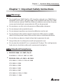
&KDSWHU ,PSRUWDQW6DIHW\,QVWUXFWLRQV
Chapter 1 : Important Safety Instructions
Warnings
z
The InsightPower SNMP IPv6 for UPS, hereafter referred to as SNMP IPv6, is
designed to work with a UPS and needs to be installed inside the UPS’s SNMP
slot or inside an external SNMP box. Before installation, ensure that all power
sources and critical loads connected to the UPS are disconnected.
z
Do not place or use this unit in the presence of flammable substances.
z
Do not attempt to disassemble the unit.
z
Do not attempt to perform any internal modifications on the unit.
z
Do not attempt to fix/ replace internal components. When repair is needed,
refer all servicing to the nearest Delta service center or authorized distributor.
z
Do not allow any objects or liquids of any kind to penetrate the unit.
z
Always follow this User Manual to install and operate this unit.
z
Do not play the included CD on a conventional CD player. This could generate
loud noise at a level that could result in permanent hearing loss.
Standard Compliance
z
EN 55022: 2006 + A1: 2007, Class B
EN 61000-3-3: 1995+A1: 2001+A2: 2005
z
EN 55024: 1998 + A1: 2001 + A2: 2003
IEC 61000-4-2: 1995+A1: 1998+A2: 2000
IEC 61000-4-3: 2006
IEC 61000-4-4: 2004
IEC 61000-4-5: 2005
IEC 61000-4-6: 2007
IEC 61000-4-8: 1993+A1: 2000
IEC 61000-4-11: 2004
Chapter 2 : Introduction
Product Description
The InsightPower SNMP IPv6 for UPS, hereafter referred to as SNMP IPv6, is a device
that provides an interface between an UPS and a network. It communicates with
the UPS, acquires its information and remotely manages the UPS via a network system. The SNMP IPv6 supports public protocols including SNMP and HTTP. You can
effortlessly configure this SNMP IPv6 using a network system and easily obtain your
UPS’s status and manage your UPS via the SNMP IPv6.
Features
z
Network UPS management
Allows remote management of the UPS from any workstation through Internet
or Intranet.
z
Remote UPS monitoring via SNMP & HTTP
Allows remote monitoring of the UPS using SNMP NMS, Delta MIB (Management
Information Base) or a Web Browser.
z
UPS and system function configuration from any client
(password protected)
Set the UPS and system parameters through a Web Browser.
z
Event logs & metering data keeping
Provides a history data of the UPS’s power events, power quality, status and
battery conditions.
Other features and supported protocols include:
z
User notification via SNMP Traps and E-mail
z
Network Time Protocol
z
Telnet configuration
z
BOOTP/ DHCP
,QVLJKW3RZHU6103,3YIRU836
&KDSWHU ,QWURGXFWLRQ
z
HTTPS, SSH, SFTP and SNMPv3 security protocols
z
RADIUS (Remote Authentication Dial In User Service) login and local
authentication
z
Remote event log management through syslog
z
IPv4 protocol
z
IPv6 protocol (IPv6 Ready Logo Phase 2 (Core for Host, Logo ID 02-C-000624)
Package Contents
Please carefully verify the SNMP IPv6 and the included accessories. Contact your
dealer if any item is missing or damaged. Should you return the items for any reason, ensure that they are carefully repacked using the original packing materials
came with the unit.
No.
Item
Quantity
InsightPower SNMP IPv6 for UPS
1 PC
RJ45 to DB9 cable
1 PC
Software & User’s Manual CD
1 PC
Setting Guide for SNMP IPv6 Card’s DIP Switches
1 PC
Cover
3 PCS
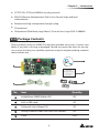
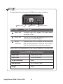
Interface
The interface includes a NETWORK port, a COM port, LED indicators, a Reset button,
DIP switches shown below. For their functions and indications, please refer to the
table below.
Top view:
1HWZRUN3RUW
/(',QGLFDWRUV
&RQVROH &20 3RUW
5HVHW%XWWRQ
',36ZLWFKHV
Front view:
1HWZRUN3RUW
21
',36ZLWFKHV
/('
,QGLFDWRUV
No. Item
Network
Port
&RQVROH
&20 3RUW
Description
Connects to the Ethernet Network.
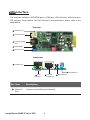
,QVLJKW3RZHU6103,3YIRU836
5HVHW%XWWRQ
&KDSWHU ,QWURGXFWLRQ
No. Item
LED
Indicators
Description
When the SNMP IPv6 is initializing or upgrading firmware, the
two LED indicators flash simultaneously to show its status. Refer
to the following:
z
Rapid simultaneous flashing (every 50ms) : Initialization
or firmware upgrade in progress.
z
Slow simultaneous flashing (every 500ms) : Initialization
failed.
WARNING : Do NOT remove the SNMP IPv6 or disconnect the UPS’s input power during initialization
or firmware upgrade! This could result in data loss
or damage to the SNMP IPv6.
The green LED indicator shows the network connection status:
z
ON : Network connection established and the IPv4 address
is useable.
z
OFF : Not connected to a network.
z
Flashes slowly (every 500ms) : Faulty IP address.
The yellow LED indicator shows the linking status between the
SNMP IPv6 and the UPS:
z
Flashes rapidly (every 50ms): UPS linked.
z
Flashes slowly (every 500ms): UPS not linked.
Console
(COM)
Port
1. Connects to a workstation with the provided RJ45 to DB9
cable to configure the system.
Reset
Button
Resets the SNMP IPv6. This does not affect the operation of the
UPS.
2. Connects to an EnviroProbe (optional) to monitor its connected environment monitoring devices.
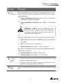
No. Item
DIP
Switches
Description
Set up operation modes.
DIP
Operation
switches
mode
21
21
21
21
Description
Normal
Mode
The SNMP IPv6 works with the UPS. It
provides the UPS’s status information
and parameters through a network system.
Pass
Through
Mode
The SNMP IPv6 stops polling the UPS
but transfers the communication data
between the console port and the UPS.
The SNMP IPv6 works with the UPS and
an optional EnviroProbe. It provides
Sensor
not only the UPS’s status information
Mode
and parameter readings, but also the
(with EnviEnviroProbe’s status information and its
roProbe
environmental parameters such as temperature and humidity.
Configuration Mode
In this mode, the user can login through
the console port and configure the
SNMP IPv6’s settings. Please refer to 4-4
Configuring through COM Port.
127(
For EnviroProbe information, please refer to the Installation Guide included
in the package of the EnviroProbe.
,QVLJKW3RZHU6103,3YIRU836
&KDSWHU ,QVWDOODWLRQ
Chapter 3 : Installation
127(
Before installation, please disconnect all power sources and critical loads connected to the UPS. Otherwise, the SNMP IPv6 might have shorting issues to
cause UPS shutdown or damage.
Please install the SNMP IPv6 inside your UPS’s SNMP slot. If your UPS does not have
any SNMP slot, please install it in an optional external SNMP box.
z
Please follow the procedures below to install the SNMP IPv6 into your UPS’s
SNMP slot.
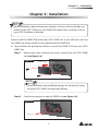
Step 1
Remove the cover and the two screws shown from the UPS’s SNMP
slot (see Figure 3-a).
Figure 3-a
UPS
SNMP slot
127(
Please note that, due to different design, the location of screws
for each UPS’s SNMP slot might be different.
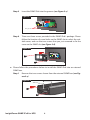
Step 2
Find the two grooves inside the SNMP slot (see Figure 3-b).
Figure 3-b
Two grooves
Step 3
Insert the SNMP IPv6 into the grooves (see Figure 3-c).
Figure 3-c
Two grooves
Step 4
There are three covers provided in the SNMP IPv6’s package. Please
follow the location of screw holes on the SNMP slot to select the suitable cover, and use the two screws that you just removed to fix the
cover on the SNMP slot (see Figure 3-d).
Figure 3-d
z
Please follow the procedures below to install the SNMP IPv6 into an external
SNMP box.
Step 1
Remove the two screws shown from the external SNMP box (see Figure 3-e).
Figure 3-e
External SNMP box
SNMP slot
,QVLJKW3RZHU6103,3YIRU836
&KDSWHU ,QVWDOODWLRQ
Step 2
Find the two grooves inside the external SNMP box (see Figure 3-f).
Figure 3-f
Two grooves
Step 3
Insert the SNMP IPv6 into the grooves (see Figure 3-g).
Figure 3-g
Two grooves
Step 4
There are three covers provided in the SNMP IPv6’s package. Please
follow the location of screw holes on the external SNMP box to select
the suitable cover, and use the two screws that you just removed to
fix the cover on the external SNMP box (see Figure 3-h).
Figure 3-h
127(
The backside view of the external SNMP box is shown as follows.
3RZHU-DFN
No. Item
563RUW
SLQ&RQQHFWRU
Description
Power Jack
Connects your UPS’s output. The input power
should be 12Vdc.
RS232 Port
Use the RS232 cable provided by your UPS to
connect your UPS’s RS232 port.
10-pin
Connector
Connects your UPS’s PC board. Please ask qualified service personnel to execute such connection. Do not perform the connection yourself.
Please refer to the table below for the external SNMP box’s specifications.
External SNMP Box Specifications
Power Jack
Input Power 12Vdc
RS232 Port
D-Sub 9-Pin Male
10-pin Connector
Male
Size (W×D×H)
92.4 x 208 x 42 mm
Weight
540 g
,QVLJKW3RZHU6103,3YIRU836
&KDSWHU 6\VWHP&RQ¿JXUDWLRQV
Chapter 4 : System Configurations
There are different ways you can configure your SNMP IPv6. If a network connection
is available at your location, the following methods can be used:
z
Web-based interface : The InsightPower SNMP IPv6 for UPS Web offers comprehensive system management and monitoring. Please refer to Chapter 5:
InsightPower SNMP IPv6 for UPS Web.
z
EzSetting : Use the provided program EzSetting to quickly set up your SNMP
IPv6. Please refer to 4-2 Configuring with EzSetting.
z
Telnet mode : Configure your SNMP IPv6 in text mode. Please refer to 4-3 Configuring via Telnet.
The above-mentioned methods require network connection. If not available, you can
use direct COM port connection to set up your SNMP IPv6. Please see 4-4 Configuring through COM Port.
127(
1. To ensure system security, it is highly recommended that you change your
account and password after the first login.
2. If you have multiple SNMP IPv6 units installed in your network, we highly
suggest that you change the SNMP IPv6’s default Host Name to avoid conflicts. Also, it is recommended that you disable BOOTP/ DHCP and manually assign a valid static IP address to the SNMP IPv6.
Configuring via InsightPower SNMP IPv6 for UPS Web
To set up the SNMP IPv6 via your web browser, please follow the instructions below:
Step 1
Use a CAT5 network cable to connect the SNMP IPv6’s Network port to
the network. Launch your web browser. In the address bar, enter the
SNMP IPv6’s default Host Name InsightPower, or default IP address
192.168.1.100. If you are unable to connect, please see Chapter 7 : Troubleshooting Q6.
127(
If you have previously changed the SNMP IPv6’s Host Name or IP address,
connect with the new settings.
Step 2
Log in as Administrator (default account/ password: admin/ password,
case sensitive).
Step 3
Specify your preferred display language (default: English) from the dropdown menu on the top right of the page. The SNMP IPv6 remembers your
language preference. In the following instructions, English is chosen as
the display language.
Step 4
Click System ʿ Administration ʿ User Manager. Manage your login
accounts and passwords under the “Local Authentication” subhead. The
access permission for the account types is shown as follows:
1) Administrator : Allowed to modify all settings.
2) Device Manager : Allowed to modify device-related settings.
3) Read Only User : Only allowed to view settings without the permission to make changes.
You can manually specify whether users are allowed to log in from other LANs. If
you wish to block login attempts from external connections, select Only in This
LAN. Otherwise, select Allow Any.
Step 5
Click System ʿ Administration ʿ TCP/ IP to set Host Name, IP address,
Subnet Mask and Gateway IP for the SNMP IPv6.
Step 6
Click Time Server to manually set time and date for the system, or enable
automatic time synchronization between the SNMP IPv6 and the time
servers.
127(
To completely set up your SNMP IPv6, please refer to Chapter 5: InsightPower SNMP IPv6 for UPS Web.
,QVLJKW3RZHU6103,3YIRU836
&KDSWHU 6\VWHP&RQ¿JXUDWLRQV
Configuring with EzSetting
Included in the provided CD, the EzSetting (compatible with Windows 2000/ 2003/
2008/ XP/ Vista/ 7) allows you to easily configure your SNMP IPv6 and upgrade firmware on your SNMP devices. Follow the instructions below:
Step 1
Use a CAT5 cable to connect the SNMP IPv6’s Network port to the network.
Step 2
Make sure the two DIP switches of the SNMP IPv6 are set to the OFF position (Normal Mode) to enable network communication. Make sure the
workstation and the SNMP IPv6 are on the same LAN.
Step 3
Insert the provided CD in the CD-ROM drive. From the root directory,
launch EzSetting.
Step 4
Click Discover to search all available SNMP devices on the LAN. A list of
devices will be shown.
127(
1. If you want to search SNMP devices in a different domain, change the
Subnet and IPv4/ IPv6 Prefix Length and click Discover.
2. If the SNMP IPv6 can not be found, check UDP port 3456 on the workstation you are using. Make sure it is open.
Step 5
Select the SNMP IPv6 that you want to modify from the Device List. Click
Modify and enter Administrator’s account and password (default: admin/
password, case sensitive).
Step 6
Click Configuration to configure network settings.
127(
Refer to Chapter 5 : InsightPower SNMP IPv6 for UPS Web for complete
configurations.
,QVLJKW3RZHU6103,3YIRU836
&KDSWHU 6\VWHP&RQ¿JXUDWLRQV
Configuring via Telnet
Step 1
Use a CAT5 network cable to connect the SNMP IPv6’s Network port to
the network.
Step 2
Connect the workstation (Windows or Linux) to the LAN that the SNMP
IPv6 is connected to.
Step 3
For Windows, launch DOS prompt mode (Start ʿ Run ʿ key in cmd
and press Enter). For Linux, launch Shell.
Step 4
Enter the following command: telnet InsightPower or telnet IP address
to initiate telnet connection with the SNMP IPv6.
Step 5
When connection is established, enter Administrator’s account and
password (default: admin/ password, case sensitive). The Main Menu will
appear on the screen. Please refer to 4-5 Configuring via Text Mode for
more information.
127(
1. The SNMP IPv6 terminates idle connections after 60 seconds.
2. Refer to Chapter 5: InsightPower SNMP IPv6 for UPS Web for complete
configurations.
Configuring through COM Port
If a network connection is not available at your location, you can still set up the
SNMP IPv6 via COM port connection. Please follow the instructions below:
127(
If you are running a non-Windows system, refer to your system’s user manual
for Telnet clients.
Step 1
Use the provided RJ45 to DB9 cable to connect the SNMP IPv6’s COM port
to the workstations’ COM port.
Step 2
Make sure the two DIP switches of the SNMP IPv6 are set to the OFF position (Normal Mode).
Step 3
For Windows 2000, 2003, 2008 and XP, go to Start ʿ Programs ʿ Accesso
ries ʿ Communications and select HyperTerminal.
127(
Microsoft has removed HyperTerminal from Windows Vista and later versions. If your operation system does not include the program, a free alternative Telnet/SSH client PuTTY can be downloaded from http://www.putty.org.
Step 4
Enter a name, choose an icon for the connection and click OK. From the
drop-down menu Connect using, select the COM port that is connected
to the SNMP IPv6.
Step 5
Click Configure and set up COM port parameters as follows:
,QVLJKW3RZHU6103,3YIRU836
&KDSWHU 6\VWHP&RQ¿JXUDWLRQV
Step 6
Click OK to continue. Set the two DIP switches of the SNMP IPv6 to the
ON position (Configuration Mode), and HyperTerminal will automatically
connect to the SNMP IPv6). If it does not connect, click the telephone icon
from the tool bar. When connection is established, log in with Administrator’s account/ password (default: admin/ password, case sensitive). Once
you are logged in, the Main Menu appears on the screen. Please refer to 4-5
Configuring via Text Mode for more information.
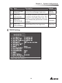
Configuring via Text Mode
You can configure the SNMP IPv6 via text mode by using Telnet/ SSH clients such as
HyperTerminal and PuTTY. In this section, you can find descriptions and default settings.
Main Menu
0DLQ0HQX
__
:HE&DUG9HUVLRQ
0$&$GGUHVVDEHH
>@8VHU0DQDJHU
>@7&3,36HWWLQJ
>@1HWZRUN3DUDPHWHU
>@7LPH6HUYHU
>@6RIW5HVWDUW
>@5HVHW$OO7R'HIDXOW
>]@([LW:LWKRXW6DYH
>@6DYH$QG([LW
3OHDVH(QWHU<RXU&KRLFH !
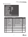
User Manager
8VHU0DQDJHU
__
5$',86
>@5$',86$XWK'LVDEOH
>@6HUYHU
>@6HFUHW
>@3RUW
/RFDO$XWK
$GPLQLVWUDWRU
>@$FFRXQWDGPLQ
>@3DVVZRUG
>@/LPLWDWLRQ2QO\LQ7KLV/$1
'HYLFH0DQDJHU
>@$FFRXQWGHYLFH
>@3DVVZRUG
>D@/LPLWDWLRQ2QO\LQ7KLV/$1
5HDG2QO\8VHU
>E@$FFRXQWXVHU
>F@3DVVZRUG
>G@/LPLWDWLRQ$OORZ$Q\
>@%DFN7R3UHYLRXV0HQX
3OHDVH(QWHU<RXU&KRLFH !
No.
Item
Description
[1]
RADIUS Auth
Specify whether RADIUS login is alDisable
lowed.
[2]
Server
The RADIUS server name.
[3]
Secret
The RADIUS secret.
[4]
Port
The RADIUS port number.
[5]
Administrator
Account
[6]
Administrator
Password
[7]
Administrator
Limitation
[8]
Device Manager
Account
[9]
Device Manager
Password
,QVLJKW3RZHU6103,3YIRU836
The default account/ password for the
Administrator (case sensitive).
Restrict Administrator login area.
Default
1812
admin
password
Only in
This LAN
The default account/ password (case device
sensitive) for the Device Manager. This
account is only permitted to change
password
device-related settings.
&KDSWHU 6\VWHP&RQ¿JXUDWLRQV
No.
Item
Description
Default
[a]
Device Manager
Limitation
Restrict Device Manager login area.
Only in
This LAN
[b]
Read Only
User Account
[c]
Read Only
User Password
[d]
Read Only
User Limitation
The default account/ password (case
user
sensitive) for Read Only User. This
account is only allowed to view settings without the permission to make password
changes.
Restrict Read Only User login area.
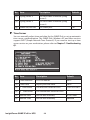
TCP/IP Setting
7&3,36HWWLQJ
__
>@,3Y$GGUHVV
>@,3Y6XEQHW0DVN
>@,3Y*DWHZD\,3
>@,3Y'16RU:,16,3
>@'+&3Y&OLHQW(QDEOH
>@,3Y$GGUHVVIHDEIIIH
>@,3Y3UHIL[/HQJWK
>@,3Y*DWHZD\,3
>@,3Y'16,3
>D@'+&3Y(QDEOH
>E@+RVW1DPH 1HW%,26 ,16,*+732:(5
>F@6\VWHP&RQWDFWRU
>G@6\VWHP/RFDWLRQ
>H@$XWR1HJRWLDWLRQ(QDEOH
>I@6SHHG0
>J@'XSOH[)XOO
>K@6WDWXV6WDEOH
>L@7HOQHW,GOH7LPH6HFRQGV
>@%DFN7R3UHYLRXV0HQX
3OHDVH(QWHU<RXU&KRLFH !
Allow Any
No.
Item
Description
Default
[1]
IPv4 Address
The IPv4 address.
192.168.001.100
[2]
IPv4 Subnet
Mask
The IPv4 subnet mask setting.
255.255.255.000
[3]
IPv4 Gateway IP The IPv4 gateway’s IP address.
192.168.001.254
[4]
IPv4 DNS or
WINS IP
IPv4 Domain Name Server or
WINS IP.
192.168.001.001
[5]
DHCPv4 Client
Enable/ Disable DHCPv4 protocol. Enable
[6]
IPv6 Address
The IPv6 address.
[7]
IPv6 Prefix
Length
The IPv6 prefix length.
[8]
IPv6 Gateway IP The IPv6 gateway’s IP address.
[9]
IPv6 DNS IP
IPv6 Domain Name Server’s IP
address.
[a]
DHCPv6
Enable/ Disable DHCPv6 protocol. Enable
[b]
Host Name
(NetBIOS)
The Host Name for the SNMP
IPv6.
[c]
System
Contact
The System Contact information.
[d]
System
Location
The System Location information.
[e]
AutoNegotiation
Enable/disable automatic transfer Enable
rate (10/ 100Mbps) negotiation.
[f ]
Speed
If the Auto-Negotiation is dis- 100M
abled, you can specify the transfer rate.
[g]
Duplex
If the Auto-Negotiation is dis- Full
abled, you can specify the duplex
mode.
[h]
Status Stable
Status change confirmation check 3
time.
[i]
Telnet Idle Time
Telnet connection time-out
setting.
,QVLJKW3RZHU6103,3YIRU836
INSIGHTPOWER
60 Seconds
&KDSWHU 6\VWHP&RQ¿JXUDWLRQV
Network Parameter
1HWZRUN3DUDPHWHU
__
>@+7736HUYHU(QDEOH
>@+77366HUYHU(QDEOH
>@7HOQHW6HUYHU(QDEOH
>@66+6)736HUYHU(QDEOH
>@)736HUYHU'LVDEOH
>@6\VORJ'LVDEOH
>@+7736HUYHU3RUW
>@+77366HUYHU3RUW
>@7HOQHW6HUYHU3RUW
>D@66+6HUYHU3RUW
>E@)736HUYHU3RUW
>F@6\VORJ6HUYHU
>G@6\VORJ6HUYHU
>H@6\VORJ6HUYHU
>I@6\VORJ6HUYHU
>J@6103*HW6HW3RUW
>@%DFN7R3UHYLRXV0HQX
3OHDVH(QWHU<RXU&KRLFH !
No.
Item
Description
Default
[1]
HTTP Server
Enable/ disable HTTP protocol.
Enable
[2]
HTTPS Server
Enable/ disable HTTPS protocol.
Enable
[3]
Telnet Server
Enable/ disable Telnet protocol.
Enable
[4]
SSH/ SFTP Server
Enable/ disable SSH/ SFTP protocol.
Enable
[5]
FTP Server
Enable/ disable FTP protocol.
Disable
[6]
Syslog
Enable/ disable remote Syslog.
Disable
[7]
HTTP Server Port
HTTP port.
80
[8]
HTTPS Server Port
HTTPS port.
443
[9]
Telnet Server Port
Telnet port.
23
[a]
SSH Server Port
SSH port.
22
[b]
FTP Server Port
FTP port.
21
[c]
Syslog Server 1
The Host Name of remote Syslog
Server 1.
[d]
Syslog Server 2
The Host Name of remote Syslog
Server 2.
No.
Item
Description
Default
[e]
Syslog Server 3
The Host Name of remote Syslog
Server 3.
[f ]
Syslog Server 4
The Host Name of remote Syslog
Server 4.
[g]
SNMP Get, Set Port
The SNMP port.
161
Time Server
You can manually adjust time and date for the SNMP IPv6 or set up automatic
time server synchronization. The SNMP IPv6, Windows XP and later versions
support SNTP (Simple Network Time Protocol). If you need to start up a time
server service on your workstation, please refer to Chapter 7: Troubleshooting
Q1.
7LPH6HUYHU
__
>@7LPH6HOHFWLRQ6173
>@7LPH=RQHKU
>@VW7LPH6HUYHU322/17325*
>@QG7LPH6HUYHU
>@0DQXDO'DWH 00''<<<<
>@0DQXDO7LPH KKPPVV
>@%DFN7R3UHYLRXV0HQX
3OHDVH(QWHU<RXU&KRLFH !
No.
Item
Description
Default
[1]
Time Selection
SNTP or manual.
SNTP
[2]
Time Zone
[3]
Adjust your time zone.
+0 hr
st
The first time server for SNTP.
POOL.NTP.ORG
nd
1 Time Server
[4]
2 Time Server
The second time server for SNTP.
[5]
Manual Date
Set the date manually.
01/01/2000
[6]
Manual Time
Set the time manually.
00:00:00
,QVLJKW3RZHU6103,3YIRU836
&KDSWHU 6\VWHP&RQ¿JXUDWLRQV
Soft Restart
Reset the SNMP IPv6. This will not affect the operation of the UPS.
Default Reset
Reset to manufacture default.
Exit Without Saving
Exit and ignore changes.
Save and Exit
Preserve your changes and exit.
Chapter 5 : InsightPower SNMP IPv6 for UPS Web
To configure the SNMP IPv6 via the InsightPower SNMP IPv6 for UPS Web, please follow the steps below:
Step 1
Make sure that your SNMP IPv6 is connected to the LAN. Use a CAT5 network cable to connect the SNMP IPv6’s Network port to the network.
Step 2
Launch your web browser. In the address bar, enter the SNMP IPv6’s Host
Name http:/InsightPower/ or IP address. For encrypted connection, enter
https://InsightPower/ or https://192.168.1.100/.
Step 3
When connection is established, the login page appears. Enter your account and password (default: admin/ password).
http://192.168.1.100/
127(
1. If you have previously changed the SNMP IPv6’s Host Name or IP address,
please connect with new settings.
2. If the login page is accessible, but you are unable to log in with correct
account and password, additional network configuration may be needed.
The cause could be the IP subnet of the computer you are logging in to is
different from the SNMP IPv6’s. To solve this issue, please refer to Chapter
7: Troubleshooting Q3.
3. The SNMP IPv6 will automatically log off idle connections after 30 minutes.
,QVLJKW3RZHU6103,3YIRU836
&KDSWHU ,QVLJKW3RZHU6103,3YIRU836:HE
The InsightPower SNMP IPv6 for UPS Web includes the information of Monitor,
Device and System. Please refer to the following sections 5-1~5-3 for more information.
Monitor
Under the Monitor category, there are Information, History and Environment these
three items.
5-1-1 Information
This includes the information of UPS Properties, Battery Parameters, In/ Out Parameters, Identification, Status Indication, and ShutdownAgent. Please note that since
different UPSs provide different information, the UPS that you have may not display
the same web page.
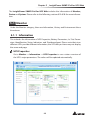
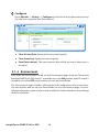
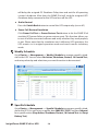
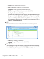
UPS Properties
Go to MonitorȻInformation ȻUPS Properties to see a status overview of
the UPS’s major parameters. The values will be updated automatically.
http://192.168.1.100/
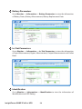
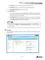
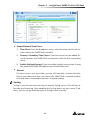
Battery Parameters
Go to MonitorȻInformationȻBattery Parameters to view the information
of Battery Status, Battery Measurement, Battery Replacement Date.
http://192.168.1.100/
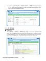
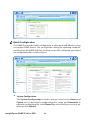
In/ Out Parameters
Go to MonitorȻInformationȻIn/ Out Parameters to view the information
of Input Measurement, Bypass Measurement, Output Measurement and Outlet
Bank.
http://192.168.1.100/
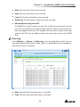
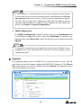
Identification
Go to MonitorȻInformationȻIdentification to view the information of
Identification and UPS Rating.
,QVLJKW3RZHU6103,3YIRU836
&KDSWHU ,QVLJKW3RZHU6103,3YIRU836:HE
http://192.168.1.100/
Status Indication
Go to MonitorȻInformationȻStatus Indication to view the UPS’s event
list. When an event occurs, its according beacon lights green.
http://192.168.1.100/
ShutdownAgent
Go to MonitorȻInformationȻShutdownAgent to view your designated
PCs’ shutdown information, including IP Address, OS (operation system), Countdown, Reason and Last Touch.
Please note that the page only appears if:
z
Your PCs have connected to a UPS using this SNMP IPv6.
z
Your PCs have installed ShutdownAgent 2012 software.
z
You have went to SystemȻAdministrationȻSNMP Trap to specify your
PCs’ IP Addresses in the Target IP bar and selected “ShutdownAgent 2012”
from Event Level’s pull-down menu.
http://192.168.1.100/
5-1-2 History
Event Log
Go to MonitorȻHistoryȻEvent LogȻPage 1/ 2/ 3/ 4... to see events that
occur. The existing ones are overwritten when the maximum number of entries
(1,000) is reached. You can also download the entire event log archive (event_
log.xls) recorded during an assigned period of time on your computer.
http://192.168.1.100/
,QVLJKW3RZHU6103,3YIRU836
&KDSWHU ,QVLJKW3RZHU6103,3YIRU836:HE
z
Date: The date when the event occurred.
z
Time: The time when the event occurred.
z
Level: The Event Level of the event occurred.
z
Event Log: The description of the event that occurred.
z
Download Event Log from UPS
The SNMP IPv6 sends a request to the UPS, collects the event logs saved in
the UPS, and replies to the user through network. Please note that this option only appears when the UPS supports this function, and the event logs
saved in the UPS may be different from the event logs saved in the SNMP
IPv6.
Data Log
Go to MonitorȻHistoryȻData Log to see all saved device data. You can
also download the data archive (data_log.xls) recorded during an assigned period of time on your computer.
http://192.168.1.100/
z
Date: The date when the data entry is recorded.
z
Time: The time when the data entry is recorded.
Configure
Go to MonitorȻHistoryȻConfigure to clear the history data and event log.
You can also assign the Save Data Interval.
http://192.168.1.100/
z
Clear History Data: Empty the history data log only.
z
Clear Event Log: Empty the event log only.
z
Save Data Interval: The time interval after which an event/ data entry is
recorded.
5-1-3 Environment
Only when an EnviroProbe is used can the Environment page show up. Please note
that the SNMP IPv6’s DIP switch 1 should be set to the ON position and DIP switch 2
should be set to the OFF position when you use an EnviroProbe.
The Environment page includes Information and Configuration these two items.
You can monitor and set up your EnviroProbe via this Environment page. For EnviroProbe information, please refer to the Installation Guide included in the package
of the EnviroProbe.
,QVLJKW3RZHU6103,3YIRU836
&KDSWHU ,QVLJKW3RZHU6103,3YIRU836:HE
Information
Go to MonitorȻEnvironmentȻInformation to see your EnviroProbe’s Sensor Information, Input Contacts and Contact Setting.
http://192.168.1.100/
Configuration
Go to MonitorȻEnvironmentȻConfiguration to configure your EnviroPobe’s Warning Threshold, Alarm Threshold, Title and Type. Please see the table
below for detailed information.
http://192.168.1.100/
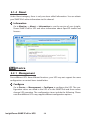
5-1-4 About
Under About category, there is only one item called Information. You can obtain
your SNMP IPv6’s other information via this channel.
Information
Go to MonitorȻAboutȻInformation to see the version of your InsightPower SNMP IPv6 for UPS and other information about OpenSSL toolkit and
licenses.
http://192.168.1.100/
Device
5-2-1 Management
Since different UPSs have different functions, your UPS may not support the same
configurations or control items stated below.
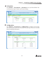
Configure
Go to DeviceȻManagementȻConfigure to configure the UPS. The configuration values are saved in the UPS or in the SNMP IPv6 and these values
change UPS operation. The configuration items include the following. Please
note that different UPSs may support different configuration options.
,QVLJKW3RZHU6103,3YIRU836
&KDSWHU ,QVLJKW3RZHU6103,3YIRU836:HE
http://192.168.1.100/
z
Auto Restart
After you click Submit to confirm your auto restart setup, the SNMP IPv6
will send the command to the UPS to enable auto restart.
z
UPS Buzzer
After you click Submit to confirm your buzzer setup, the SNMP IPv6 will
send the command to the UPS to enable buzzer.
z
Voltage Sensitivity
After you set up your voltage sensitivity (there are Normal, Reduced, and
Low selections) and click Submit, the SNMP IPv6 will send the command to
the UPS to enable the UPS’s voltage sensitivity function.
z
Transfer Voltage
After you click Submit to confirm your transfer voltage setup, the SNMP
IPv6 will send the command to the UPS to enable the relevant functions.
z
Low Battery
This configuration saves the setup values in the SNMP IPv6 and compares
with the values received from the UPS. If the received battery level is lower
than the assigned one, the SNMP IPv6 will trigger a low-battery alarm.
z
UPS Shutdown Action
This configuration saves your setup values in the SNMP IPv6 and compares
with the values received from the UPS. If an event like power failure or low
battery occurs, the SNMP IPv6 will send the assigned shutdown delay command to the UPS.
z
Smart Shutdown
The Smart Shutdown configuration is used to safely shutdown all of the
connected computers and the UPS. First of all, you should estimate the longest OS Shutdown Delay time for your operating systems that have been installed shutdown software and connected to the SNMP IPv6. The SNMP IPv6
will delay the assigned OS Shutdown Delay time and wait for all operating
systems’ shutdown. After that, the SNMP IPv6 will send the assigned UPS
shutdown-delay command to the UPS and turn off the UPS.
z
Battery Replacement Date
After you set up battery replacement dates, the SNMP IPv6 will send the
command to the UPS and save the information in the UPS.
z
External Battery Pack
After you click Submit to confirm your external battery pack setup, the
SNMP IPv6 will send the command to the UPS and save the external battery
pack quantity in the UPS.
z
Bypass Transfer Frequency
After you set a tolerance of bypass transfer frequency and confirm your setup, the SNMP IPv6 will send the command to the UPS. If the UPS transfers to
bypass mode and the bypass frequency is out of the tolerance, output will
be turned off and critical loads will be protected.
z
Bypass Transfer Voltage
After you set a tolerance of bypass transfer voltage and confirm your setup,
the SNMP IPv6 will send the command to the UPS. If the UPS transfers to
bypass mode and the bypass voltage is out of the tolerance, output will be
turned off and critical loads will be protected.
z
Periodic Auto Test
This configuration is used to set up battery test time. After you confirm your
setup, the SNMP IPv6 will send the command to the UPS and save the setup
in the UPS. When the test time is due, the UPS will automatically perform
the battery test.
z
Output Dry Contacts
After you click Submit to confirm your setup of output dry contacts, the
SNMP IPv6 will send the command to the UPS, save the values in the UPS,
and report the current UPS’s status.
,QVLJKW3RZHU6103,3YIRU836
&KDSWHU ,QVLJKW3RZHU6103,3YIRU836:HE
Control
Go to DeviceȻManagementȻControl to configure relevant control commands. After you click Submit, the SNMP IPv6 will send the according commands to the UPS to enable relevant functions. The control items include the
following.
http://192.168.1.100/
z
Battery Test
After you select the battery test type and click Submit, the SNMP IPv6 will
send the command to the UPS to enable the battery test accordingly.
z
Shutdown & Restart UPS Only
After you confirm your setup, the SNMP IPv6 will send the command to the
UPS to shut down or/ and restart the UPS.
If you want to shutdown the UPS, please check the UPS Shutdown Delay
box and key in delay time.
If you want to restart the UPS, please check the UPS Restart Delay box and
key in delay time.
If you want to shutdown and restart the UPS, please check both of the boxes and key in according delay time.
z
Smart Shutdown
The Smart Shutdown configuration is used to safely shutdown all of the
connected computers and the UPS. First of all, you should estimate the longest OS Shutdown Delay time for your operating systems that have been installed shutdown software and connected to the SNMP IPv6. The SNMP IPv6
will delay the assigned OS Shutdown Delay time and wait for all operating
systems’ shutdown. After that, the SNMP IPv6 will send the assigned UPS
shutdown-delay command to the UPS and turn off the UPS.
z
Outlet Control
Press the Switch Bank button to control the UPS output relay (on or off ).
z
Power Fail/ Restore Simulation
Click Power Fail Test or Power Restore Test button to let the SNMP IPv6
simulate UPS power failure or power restore event. This function allows you
to test all of the connected software and verify whether they work properly
or not. Please note that the simulation won’t influence UPS operation, the
UPS remains in its original operation mode and won’t transfer to battery
mode.
Weekly Schedule
Go to DeviceȻManagementȻWeekly Schedule to arrange a weekly schedule for the UPS. You can select No Action, Shutdown, Restart, 10-Second Test,
and set up what day and what time you want the action to be executed.
http://192.168.1.100/
Specific Schedule
Go to DeviceȻManagementȻSpecific Schedule to arrange a specific schedule for the UPS. You can set up a specific date (MM/ DD/ YYYY) and time (hh:mm)
for a specific action (Stop Action, Shutdown, Restart, 10-Second Test and Deep
Battery Test).
,QVLJKW3RZHU6103,3YIRU836
&KDSWHU ,QVLJKW3RZHU6103,3YIRU836:HE
http://192.168.1.100/
Event Level
Go to DeviceȻManagementȻEvent Level to set up a level for an event.
If you want to receive an event notification, please refer to 5-3-2 Notification SNMP Trap and 5-3-2 Notification - Mail Server.
http://192.168.1.100/
System
Only Administrator can see the System page. Under the System category, there are
Administration and Notification these two items. You can use them to change or
look up the system’s relevant settings or records. Please see below for more descriptions.
5-3-1 Administration
The Administration page includes User Manager, TCP/ IP, Web, Console, FTP, Time
Server, Syslog, Batch Configuration, and Upgrade these nine selections.
User Manager
The SNMP IPv6 supports RADIUS. Check the Use RADIUS box, key in required
information including Server, Secret and Port (default: 1812) and click Submit
to enable RADIUS. You can define service types for Administrator, Device Manager and Read Only User. If RADIUS is disabled, you can still manage the Account Name, Password and Login Limitation for Local Authentication.
http://192.168.1.100/
,QVLJKW3RZHU6103,3YIRU836
&KDSWHU ,QVLJKW3RZHU6103,3YIRU836:HE
TCP/ IP
This allows Administrator to configure local network parameters for the SNMP
IPv6.
http://192.168.1.100/
z
TCP/ IP Settings for IPv4
1) DHCP Client: Enable/ Disable DHCP. If enabled, DHCP server automatically assigns an IP address to the SNMP IPv6.
2) IP Address: The IP address in dotted format.
3) Subnet Mask: The Subnet Mask for your network.
4) Gateway IP: The IP address for network gateway in dotted format.
5) DNS IP: The IP address Domain Name Server in dotted format.
6) Search Domain: If the Host Name you provided cannot be found, the
system appends the search domain to your Host Name.
z
TCP/ IP Settings for IPv6
1) DHCP Client: Enable/ Disable DHCP. If enabled, DHCP server automatically assigns an IP address to the SNMP IPv6.
2) IP Address: The IPv6 address.
3) Prefix Length: The prefix length for the IPv6 address.
4) Gateway V6IP: The IP address for the IPv6 network gateway.
5) DNS V6IP: The IP address for the IPv6 domain name server.
z
System
1) Host Name: The SNMP IPv6 Host Name on the network.
2) System Contact: System contact information.
3) System Location: System location information.
z
Link
1) Auto-Negotiation: Enable/ Disable automatic transfer rate (10/ 100M
bps) negotiation.
2) Speed: If the Auto-Negotiation is disabled, you can specify the transfer
rate.
3) Duplex: If the Auto-Negotiation is disabled, you can specify the duplex
mode.
Web
This allows Administrator to enable/ disable HTTP/ HTTPS communication protocols.
http://192.168.1.100/
z
Web
1) HTTP: Enable/ disable HTTP connection.
2) HTTPS: Enable/ disable HTTPS connection.
,QVLJKW3RZHU6103,3YIRU836
&KDSWHU ,QVLJKW3RZHU6103,3YIRU836:HE
3) HTTP Port: Assign an HTTP port number (default: 80).
4) HTTPS Port: Assign an HTTPS port number (default: 443).
5) Web Refresh Period: Web refresh interval.
z
SSL Certificate
1) To ensure connection security between the SNMP IPv6 and the connecting workstation, SSL certificate can be used to encrypt and secure
the integrity of transmitting data.
2) Certificate File: This allows you to replace your own SSL certificate file.
The SNMP IPv6 supports PEM format which is generated by OpenSSL.
Click Choose File to upload a certificate file.
127(
For more information about generating a private SSL certificate file,
please refer to Chapter 7: Troubleshooting Q12, or visit http://www.
openssl.org/.
Console
This item allows the Administrator to enable or disable Telnet/ SSH communication protocols.
http://192.168.1.100/
z
Telnet: Enable/ disable Telnet connection.
z
SSH/ SFTP: Enable/ disable SSH/ SFTP connection.
z
Telnet Port: Assign a Telnet port number (default: 23).
z
SSH Port: Assign an SSH protocol port number (default: 22).
z
Host Key/ Authentication Public Key:
This allows you to replace your own SSH keys. The SNMP IPv6 supports key
files generated by OpenSSH, including DSA, RSA, and Authentication Public
Keys. How to generate DSA, RSA, and Authentication Public keys for SSH,
please refer to Chapter 7 : Troubleshooting Q13. You can use this page or
SFTP protocol to upload key files. For detailed information, please refer to
Chapter 7 : Troubleshooting Q14.
FTP
This allows Administrator to enable/ disable FTP communication protocol.
http://192.168.1.100/
z
FTP: Enable/ disable FTP connection.
z
FTP Port: Assign an FTP port number (default: 21).
Time Server
You can manually set the time and date, or allow automatic time synchronization with SNTP servers. Please note that if the SNTP server is not responsive, the
event and data log will not register even when SNTP is enabled.
,QVLJKW3RZHU6103,3YIRU836
&KDSWHU ,QVLJKW3RZHU6103,3YIRU836:HE
http://192.168.1.100/
z
Simple Network Time Server
1) Time Zone: From the dropdown menu, select the time zone for the location where the SNMP IPv6 is located.
2) Primary/ Secondary Time Server: Two time servers can be added. Every 60 minutes, the SNMP IPv6 synchronizes with the first responding
server.
3) Enable Daylight Saving: Check to enable daylight saving time. During
this period, the SNMP IPv6 adjusts time forward one hour.
z
Manual
If a time server is not accessible, you can still manually set time and date.
Please note that every time you restart the SNMP IPv6’s network module,
time and date is reinstated to previous assigned settings.
Syslog
Syslog is used to store the event log on remote Syslog servers. This will not affect the local event log. After enabling the Syslog, please set up a server IP address. You can set up at maximum four Syslog servers at a time.
http://192.168.1.100/
Batch Configuration
The SNMP IPv6 provides batch configuration to allow quick and effortless setup
on multiple SNMP devices. You can duplicate settings by exporting configuration files from the SNMP IPv6 that you have successfully configured, and import
the configuration files on other devices.
http://192.168.1.100/
z
System Configuration
The System Configuration includes settings saved in the Device and
System tabs. To download a configuration file, simply click Download. To
upload a configuration file, click Choose File, select the file you wish to upload, and click Upload.
,QVLJKW3RZHU6103,3YIRU836
&KDSWHU ,QVLJKW3RZHU6103,3YIRU836:HE
127(
If the IP address is static and you wish to copy settings to other devices
on the same LAN, you must manually remove the following line IP=xxx.
xxx.xxx.xxx under the [System] section from the exported configuration file. You can open the configuration file with text editors such as
Notepad and WordPad. To modify/ assign IP address for the SNMP IPv6,
please see Chapter 4: System Configurations.
z
SNMP Configuration
The SNMP Configuration includes settings saved in the Notification tab.
To download a configuration file, simply click Download. To upload a configuration file, click Choose File, select the file you wish to upload, and click
Upload.
127(
If you need to modify the command lines, please do not delete the unmodified ones. They should be left intact to assure the integrity of the
configuration file.
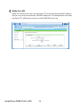
Upgrade
The Upgrade page shows the SNMP IPv6’s current firmware version. The Administrator can use this page to update the SNMP IPv6’s firmware. Click Choose
File, select the file you wish to upload, and click Upload. The upgrade process
should take about one minute.
http://192.168.1.100/
5-3-2 Notification
The Notification page includes SNMP Access, SNMPv3 USM, SNMP Trap, Mail Server,
Wake On LAN these five items.
SNMP Access
http://192.168.1.100/
The SNMP IPv6 supports SNMP protocol and SNMP NMS (Network Management System), which are commonly used to monitor network devices for conditions that call for administrative attention. To prevent unauthorized access, you
can specify the NMS IP addresses that are allowed to access, their community
strings and access levels. The maximum number of IP entries is 256.
127(
If IP address 0.0.0.0 is enlisted, the NMS IP access restriction is ignored.
The SNMP IPv6 checks the community string to identify the access level
and permission according to your setting.
SNMPv3 USM
SNMPv3 offers features such as the encryption of packets and authentication to
improve security. The SNMPv3 USM (User Session Management) allows you to
assign eight User Names whose access is granted via SNMPv3 protocol. You can
also define their respective Security Levels, Auth Passwords, Priv Passwords and
Access Levels.
,QVLJKW3RZHU6103,3YIRU836
&KDSWHU ,QVLJKW3RZHU6103,3YIRU836:HE
http://192.168.1.100/
SNMP Trap
SNMP Trap alerts users to event occurrences in your monitored environment. To
enable SNMP Trap, you must add Target IP addresses to the Target IP list. Specify
the Community String, Trap Type, MIB, SNMPv3 User Name, Trap port, Event
Level, SNMP Port for ShutdownAgent and click Add. If you wish to update or
delete a Target IP address, specify the IP address in the Target IP list, and click
Update or Delete.
http://192.168.1.100/
127(
The SNMP IPv6 supports SNMPv1, SNMPv2c and SNMPv3 traps to satisfy
most of customers’ environments. If you select the SNMPv3 trap, please
specify an SNMPv3 USM User Name.
You can use Event Level to determine what event notifications should
be sent to which Target IP Address. Five event levels are listed as follows:
z None: No event notifications are sent to the target address.
z Information: All event notifications are sent to the target address.
z Warning:
Both Warning and Alarm event notifications are sent to
the target address.
z Alarm: Only Alarm event notifications are sent to the target address.
z ShutdownAgent:
All event notifications are sent to the target address, and you can go to MonitorȻInformationȻShutdownAgent to review your designated PCs’ shutdown information.
You can go to DeviceȻManagementȻEvent Level to change the
event level.
Mail Server
http://192.168.1.100/
,QVLJKW3RZHU6103,3YIRU836
&KDSWHU ,QVLJKW3RZHU6103,3YIRU836:HE
You can set up an SMTP Server and specify a list of E-mail recipients who will receive notifications when events occur. The maximum number of recipients is 256.
127(
If a DNS server is not available in the network, you need to manually assign an SMTP server address to enable the E-mail notification system.
z
SMTP Server Name or IP
If a Host Name is entered, a DNS IP should be added in TCP/ IP. Please see
5-3-1 Administration – TCP/ IP.
z
Account
The mail server login account.
z
Password
The mail server login password.
z
Receiver
The recipients’ E-mail addresses.
z
Event Level
Select the Event Level that when triggered, an E-mail notification is sent to
the corresponding recipient.
1) Information: All event notifications are sent to the target address.
2) Warning: Warning and Alarm event notifications are sent to the target
address.
3) Alarm: Only Alarm event notifications are to the target address.
Wake On LAN
Wake On LAN function can start up clients’ PCs from network with MAC address,
and you can set up at maximum 256 MAC addresses. The configuration can wake
up clients’ PCs after power restores or the SNMP IPv6 starts up.
http://192.168.1.100/
,QVLJKW3RZHU6103,3YIRU836
&KDSWHU 6103'HYLFH)LUPZDUH8SJUDGH
Chapter 6 : SNMP Device Firmware Upgrade
With the provided program EzSetting, you can effortlessly perform a firmware upgrade on your SNMP devices via LAN. Please refer to the following instructions.
Step 1
The subnet mask allows you to define the device discovery range in the
specified subnets. Make sure the SNMP device you wish to upgrade is in
the subnet that is specified. If it is not, please modify the subnet and subnet mask.
Step 2
Click Discover. A list of SNMP devices is shown.
Step 3
Select a device from the Device List, click Modify, and enter Administrator account and password.
,QVLJKW3RZHU6103,3YIRU836
&KDSWHU 6103'HYLFH)LUPZDUH8SJUDGH
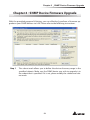
Step 4
Click Upgrade. The upgrade dialog box pops up. Click Browse to select
a valid firmware binary file. Verify the firmware version shown under File
Information, and then click Upgrade Now to continue.
Step 5
The upgrade process should take about 20 seconds.
Step 6
When the upgrade is completed, the following dialog box appears. It
takes about 1 minute for the device to reboot.
Chapter 7 : Troubleshooting
Q1. How to set up an SNTP server on my workstation for the SNMP IPv6 to synchronize?
To enable SNTP services in Windows XP, go to StartȻControl PanelȻAdd/
Remove ProgramsȻAdd/ Remove Windows ComponentsȻNetworking
ServicesȻcheck Simple TCP/ IP ServicesȻOK. To enable time synchronization, you need to set SNTP time server addresses in Time Server. Please refer
to Chapter 4: System Configurations.
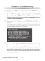
Q2. How to make sure the linking between the SNMP IPv6’s and the UPS is established?
If the linking between the SNMP IPv6 and the UPS is correctly established, the
yellow LED indicator should flash rapidly. If not, confirm that the device ID setting on the SNMP IPv6 and the UPS is consistent.
&?!SLQJ
3LQJLQJZLWKE\WHVRIGDWD
5HSO\IURPE\WHV WLPH PV77/
5HSO\IURPE\WHV WLPH PV77/
5HSO\IURPE\WHV WLPH PV77/
5HSO\IURPE\WHV WLPH PV77/
3LQJVWDWLVWLFVIRU
3DFNHWV6HQW 5HFHLYHG /RVW ORVV $SSUR[LPDWHURXQGWULSWLPHVLQPLOOLVHFRQGV
0LQLPXP PV0D[LPXP PV$YHUDJH PV
&?!
Q3. I can access the InsightPower SNMP IPv6 for UPS Web, but I cannot login
in.
Please check the IP addresses of the SNMP IPv6 and the workstation on which
you are trying to log in. By default, they must be within the same LAN so you
can connect via the web interface. You can enable external connections to
solve this issue. To do this, launch EzSetting and change User Limitation to Allow Any, as shown below.
,QVLJKW3RZHU6103,3YIRU836
&KDSWHU 7URXEOHVKRRWLQJ
Q4. Unable to connect to the SNMP IPv6 via its Host Name?
If you just assign a new static IP address to the SNMP IPv6, you may need to
refresh the NetBIOS table so that it corresponds with the new setting. Although
Windows updates its NetBIOS table periodically, you can still manually force
it to refresh by entering the following command nbtstat –R in DOS prompt
mode. After that, you can now connect to the SNMP IPv6 by its Host Name.
Please also ensure that the Host Name assigned to the SNMP IPv6 does not exceed 16 bytes.
Q5. How to check my workstation’s IP address?
For Windows, please enter ipconfig /all in DOS prompt mode. For UNIX, please
enter ifconfig in shell. You should be able to check your IP and MAC (Physical
Address) now.
3K\VLFDO$GGUHVV'$$&
'+&3(QDEOHG<HV
$XWRFRQILJXUDWLRQ(QDEOHG<HV
/LQNORFDO,3Y$GGUHVVIHDGEEFHIF 3UHIHUUHG
,3Y$GGUHVV 3UHIHUUHG
6XEQHW0DVN
&?!
Q6. Unable to ping the SNMP IPv6 from my workstation?
If the SNMP IPv6 is non-responsive, check the following:
1) If the green LED indicator on the SNMP IPv6 is OFF, check if the network
cable is correctly connected from the SNMP IPv6 to the router or hub.
2) If the green LED indicator is ON, the current IP address could be unreachable. Manually assign a valid IP address to the SNMP IPv6.
3) If the green LED indicator flashes and (1) your network configuration includes a DHCP server, make sure the DHCP service is working properly; (2)
Otherwise, make sure the assigned IP is not already taken on the network.
Please note that if the current configuration is not useable, the SNMP IPv6
will reset to default IP settings (IPv4 address: 192.168.1.100/ net mask:
255.255.255.0/ gateway: 192.168.1.254).
4) If the problem persists, use a network cable to cross link your SNMP IPv6
and the workstation. Ping the SNMP IPv6’s default or static IP address, according to your configurations. If a ping response is successfully received,
indicating that the SNMP IPv6 is working properly, check your network
equipment. If not, contact your local dealer or service personnel for assistance.
Q7. Unable to perform an SNMP Get command?
Refer to 5-3-2 Notification to check SNMP settings. Make sure that the workstation’s IP address is added to the NMS IP list with Read or Read/ Write access.
The community string on the workstation and the SNMP IPv6 must match.
Q8. Unable to perform an SNMP Set command?
Refer to 5-3-2 Notification to check SNMP settings. Make sure that the workstation’s IP address is added to the NMS IP list, with Read/ Write permission. The
community string on the PC and the SNMP IPv6 must match.
Q9. Unable to receive SNMP trap?
Refer to 5-3-2 Notification to check SNMP Trap settings. Make sure that the
workstation’s IP address is added to the Target IP list.
,QVLJKW3RZHU6103,3YIRU836
&KDSWHU 7URXEOHVKRRWLQJ
Q10. Forgot Administrator’s account and password?
You can reset Administrator’s account and password via text mode. Refer to 4-4
Configuring via COM Port to establish a COM port connection with the SNMP
IPv6. When the login information is prompted, key in rstadmin within 30 seconds and press enter. The Administrator account and password are now reset
to default (admin/ password).
Q11. How to enable IPv6 in Windows XP?
If you are running Windows XP, please enable IPv6 first (click STARTȻ
RUN, and enter ipv6 install). The SNMP IPv6 supports IPv6 with no additional
configurations required. However, please note that IPv6 is automatically disabled if an identical LLA (Local-link Address) already exists on the LAN. If the
SNMP IPv6 obtains both IPv4 and IPv6 records from DNS resolution, the IPv4 is
used as the primary IP address for the given Host Name.
To learn more information regarding IPv6 compatibility, please visit IETF (http://
tools.ietf.org/html), or IPv6 Ready Logo Program (http://www.ipv6ready.org).
Q12. How to generate a private SSL certificate file (in PEM format) for HTTPs
connection?
To ensure connection security between the SNMP IPv6 and your workstation, you can create your own SSL certificate file. Please download and install
OpenSSL Toolkit from http://www.openssl.org. Launch Shell or DOS prompt
mode and enter the following command to create your own certificate file:
RSHQVVO UHT ±[ ±QRGHV ±GD\V ±QHZNH\
UVD±NH\RXWFHUWSHP±RXWFHUWSHP
1) Answer the prompted questions. Proceed with the given directions. Once
it is completed, a file named cert.pem is created in the current working directory.
2) Upload cert.pem to the InsightPower SNMP IPv6 for UPS Web. Please refer
to 5-3-1 Administration – Web.
Q13. How to generate DSA, RSA and Public keys for SSH?
For Linux:
1) Please download and install OpenSSH from http://www.openssh.org.
2) Launch Shell and enter the following commands to create your own keys
(please ignore it when prompted to provide passphrase):
'6$.H\VVKNH\JHQ±WGVD
56$.H\VVKNH\JHQ±WUVD
3) Upload DSA and RSA keys to the InsightPower SNMP IPv6 for UPS Web.
Please refer to 5-3-1 Administration – Console for more information.
For Windows:
1) Please download and install PuTTY from http://www.putty.org.
2) Run puttygen.exe from the installed directory.
3) Select SSH-2 RSA from the Parameters area and click KeyȻGenerate
key pair to generate a RSA key.
4) Click ConversionsȻExport OpenSSH Key and assign a filename to the
RSA key. Please ignore it when prompted to provide key passphrase.
5) Select SSH-2 DSA from the Parameters, clickt KeyȻGenerate key pair to
generate a DSA key.
6) Click ConversionsȻExport OpenSSH Key and assign a filename to the
DSA key. Please ignore it when prompted to provide key passphrase.
7) Copy the generated key from the text box, paste in a text editor and save
as a text file.
,QVLJKW3RZHU6103,3YIRU836
&KDSWHU 7URXEOHVKRRWLQJ
8) Upload the DSA/ RSA/ Public keys files to the InsightPower SNMP IPv6 for
UPS Web. Refer to 5-3-1 Administration – Console for more information.
Q14. How to upload configuration / firmware / key files via SSH/ SFTP?
To quickly configure your SNMP IPv6, you can upload the files via SSH/ SFTP.
The SNMP IPv6 automatically imports your settings after the files are uploaded
to the designated directories. Refer to the following table:
Directory
Files
\config_snmp
snmp.ini
\config_system
configure.ini
\ssh_dsa
DSA key
\ssh_rsa
RSA key
\ssh_pubkey
Public key
\upgrade_snmp
SNMP IPv6’s firmware upgrade package (binary)
\upgrade_device*
Device’s firmware upgrade package (binary)
*Appears on specific devices only.
Upload files to their respective directories. Make sure the filenames do not
contain non-English characters to avoid read error. Overwrite existing files if
prompted by your SFTP client.
Q15. How to test SNMPv3 in Linux?
Before you can access the SNMP OID (Object Identifier) via SNMPv3 protocol,
the SNMPv3 USM table must be organized. Please refer to 5-2-2 Notification –
SNMPv3 USM for more information.
To test SNMPv3 in Linux, launch shell and key in the following command:
VQPSZDON Y X XVHU! O DXWK3ULY $ SDVV
ZRUG! ; SDVVZRUG! Q FRQWH[W QDPH! W LS!
-v: 1 for SNMPv1, 3 for SNMPv3.
-l: Follow the security levels. They are: noAuthNoPriv, authNoPriv and authPriv.
-u: The user name which is assigned from SNMPv3 USM table.
-A: The Auth Password which is assigned from SNMPv3 USM table.
-X: The Priv Password which is assigned from SNMPv3 USM table.
-n: The Context Name which is assigned from SNMPv3 USM table.
-t: Timeout in seconds.
<ip>: The IP address of the SNMP IPv6.
<oid>: The next available SNMP OID (for example: 1.3.6.1.2.1.1.1.0). Please refer
to the RFC1213 MIB.
,QVLJKW3RZHU6103,3YIRU836
$SSHQGL[$ 6SHFL¿FDWLRQV
Appendix A : Specifications
Model Name
InsightPower SNMP IPv6
Power Input
12 Vdc
Power Consumption
2 Watt (Max.)
Network Connection
RJ-45 jack connector (10/ 100M)
Physical
Size (W x D )
130 mm x 60 mm
Weight
75 g
Environmental
Operating Temperature
0 ~ 60濎
Storage Temperature
-40 ~ 125濎
Operating Humidity
0 ~ 90 % (Non-condensing)
127(
* Refer to the rating label for the safety rating.
* All specifications are subject to change without prior notice.
Appendix B : Warranty
Seller warrants this product, if used in accordance with all applicable instructions,
to be free from original defects in material and workmanship within the warranty
period. If the product has any failure problem within the warranty period, Seller will
repair or replace the product at its sole discretion according to the failure situation.
This warranty does not apply to normal wear or to damage resulting from improper
installation, operation, usage, maintenance or irresistible force (i.e. war, fire, natural
disaster, etc.), and this warranty also expressly excludes all incidental and consequential damages.
Maintenance service for a fee is provided for any damage out of the warranty period.
If any maintenance is required, please directly contact the supplier or Seller.
WARNING : The individual user should take care to determine prior to
use whether the environment and the load characteristic are suitable,
adequate or safe for the installation and the usage of this product. The
User Manual must be carefully followed. Seller makes no representation or warranty as to the suitability or fitness of this product for any
specific application.
,QVLJKW3RZHU6103,3YIRU836
NO.UMEN3915100975-S35UPS130227