1
SimMechanics™
Visualization and Import Guide
R2011b
How to Contact MathWorks
Latest news:
www.mathworks.com
Sales and services:
www.mathworks.com/sales_and_services
User community:
www.mathworks.com/matlabcentral
Technical support:
www.mathworks.com/support/contact_us
Phone:
508-647-7000
The MathWorks, Inc.
3 Apple Hill Drive
Natick, MA 01760-2098
SimMechanics™ Visualization and Import Guide
© COPYRIGHT 2001–2012 by The MathWorks, Inc.
The software described in this document is furnished under a license agreement. The software may be used
or copied only under the terms of the license agreement. No part of this manual may be photocopied or
reproduced in any form without prior written consent from The MathWorks, Inc.
FEDERAL ACQUISITION: This provision applies to all acquisitions of the Program and Documentation
by, for, or through the federal government of the United States. By accepting delivery of the Program
or Documentation, the government hereby agrees that this software or documentation qualifies as
commercial computer software or commercial computer software documentation as such terms are used
or defined in FAR 12.212, DFARS Part 227.72, and DFARS 252.227-7014. Accordingly, the terms and
conditions of this Agreement and only those rights specified in this Agreement, shall pertain to and
govern the use, modification, reproduction, release, performance, display, and disclosure of the Program
and Documentation by the federal government (or other entity acquiring for or through the federal
government) and shall supersede any conflicting contractual terms or conditions. If this License fails
to meet the government's needs or is inconsistent in any respect with federal procurement law, the
government agrees to return the Program and Documentation, unused, to The MathWorks, Inc.
Trademarks
MATLAB and Simulink are registered trademarks of The MathWorks, Inc. See
www.mathworks.com/trademarks for a list of additional trademarks. Other product or brand
names may be trademarks or registered trademarks of their respective holders.
Patents
MathWorks products are protected by one or more U.S. patents. Please see
www.mathworks.com/patents for more information.
Revision History
October 2008
March 2009
September 2009
March 2010
September 2010
April 2011
September 2011
Online only
Online only
Online only
Online only
Online only
Online only
Online only
New for Version 3.0 (Release 2008b)
Revised for Version 3.1 (Release 2009a)
Revised for Version 3.1.1 (Release 2009b)
Revised for Version 3.2 (Release 2010a)
Revised for Version 3.2.1 (Release 2010b)
Revised for Version 3.2.2 (Release 2011a)
Revised for Version 3.2.3 (Release 2011b)
Contents
1
2
Introducing Visualization and Animation
About SimMechanics Visualization . . . . . . . . . . . . . . . . . . . . .
Starting Visualization . . . . . . . . . . . . . . . . . . . . . . . . . . . . . .
Using Visualization . . . . . . . . . . . . . . . . . . . . . . . . . . . . . . . .
1-2
1-2
1-3
About Body Color and Geometry . . . . . . . . . . . . . . . . . . . . . . .
About Body Color: Default and Custom . . . . . . . . . . . . . . . . .
About Body Geometry: Default, Standard, and Custom . . . . .
Standard Body Geometry: Equivalent Ellipsoids . . . . . . . . . .
Standard Body Geometry: Convex Hulls . . . . . . . . . . . . . . . .
Custom Body Geometry and External Graphics Files . . . . .
1-5
1-5
1-5
1-5
1-8
1-10
Hierarchy of Body, Machine, and Model Visualization
Settings . . . . . . . . . . . . . . . . . . . . . . . . . . . . . . . . . . . . . . . . .
Visualized Geometries and Colors from Body Block Settings
Body Block Settings Affecting Body Visualization . . . . . . . .
Visualization Settings in the Machine and Model Hierarchy
1-11
1-11
1-12
1-13
Getting Started with the Visualization Window
Introducing the SimMechanics Visualization Window . . . . .
About the Visualization Window . . . . . . . . . . . . . . . . . . . . . .
Opening and Updating the Visualization Window . . . . . . . . .
Visualization Toolbar and Its Controls . . . . . . . . . . . . . . . . .
2-2
2-2
2-2
2-4
Controlling Body and Body Component Display . . . . . . . . . .
About Body and Body Component Display . . . . . . . . . . . . . .
Interpreting the Body Display Symbols and Shapes . . . . . . .
Changing Body Display Symbols . . . . . . . . . . . . . . . . . . . . . .
2-6
2-6
2-6
2-7
iii
iv
Contents
Changing Body Display Shapes . . . . . . . . . . . . . . . . . . . . . . .
2-7
Adjusting the Camera View . . . . . . . . . . . . . . . . . . . . . . . . . . .
Setting the Background Color . . . . . . . . . . . . . . . . . . . . . . . .
Interpreting the Camera Projection, Field of View, and
Viewpoint . . . . . . . . . . . . . . . . . . . . . . . . . . . . . . . . . . . . .
Automatically Sizing the Camera Field of View . . . . . . . . . .
Automatically Setting a Camera Viewpoint . . . . . . . . . . . . .
Actively Controlling the Camera Viewpoint . . . . . . . . . . . . .
Camera Viewpoint and Mouse Controls . . . . . . . . . . . . . . . .
2-9
2-9
2-9
2-11
2-12
2-13
2-14
Communicating with the Model from the Visualization
Window . . . . . . . . . . . . . . . . . . . . . . . . . . . . . . . . . . . . . . . . .
Highlighting Bodies, Body Components, and Body Blocks . .
Updating the Model Diagram . . . . . . . . . . . . . . . . . . . . . . .
Saving Visualization Settings to the Model . . . . . . . . . . . . .
2-16
2-16
2-17
2-18
Controlling Simulation from the Visualization Window . . .
Starting, Pausing, and Stopping the Simulation . . . . . . . . .
Timing the Simulation . . . . . . . . . . . . . . . . . . . . . . . . . . . .
2-20
2-20
2-20
Controlling Animation . . . . . . . . . . . . . . . . . . . . . . . . . . . . . .
About Animation . . . . . . . . . . . . . . . . . . . . . . . . . . . . . . . . .
How Animation Works . . . . . . . . . . . . . . . . . . . . . . . . . . . .
Automatically Adapting the Camera View to the Displayed
Motion . . . . . . . . . . . . . . . . . . . . . . . . . . . . . . . . . . . . . . .
Changing How the Animation Is Updated . . . . . . . . . . . . . .
Speeding Up the Animation in Real Time . . . . . . . . . . . . . .
2-22
2-22
2-22
2-23
2-24
2-25
Recording Animation . . . . . . . . . . . . . . . . . . . . . . . . . . . . . . .
About Recording . . . . . . . . . . . . . . . . . . . . . . . . . . . . . . . . .
How Recording Works . . . . . . . . . . . . . . . . . . . . . . . . . . . . .
Recording Animations . . . . . . . . . . . . . . . . . . . . . . . . . . . . .
Compressing Animation Recordings . . . . . . . . . . . . . . . . . .
Controlling the Size of the Recorded Animation . . . . . . . . .
Playing Recordings of Animation . . . . . . . . . . . . . . . . . . . .
2-27
2-27
2-27
2-27
2-29
2-30
2-30
SimMechanics Visualization Menus and Their Controls . .
About the Visualization Window Menus . . . . . . . . . . . . . . .
View Menu . . . . . . . . . . . . . . . . . . . . . . . . . . . . . . . . . . . . .
Simulation Menu . . . . . . . . . . . . . . . . . . . . . . . . . . . . . . . . .
Model Menu . . . . . . . . . . . . . . . . . . . . . . . . . . . . . . . . . . . .
Help Menu . . . . . . . . . . . . . . . . . . . . . . . . . . . . . . . . . . . . .
2-32
2-32
2-33
2-34
2-36
2-37
3
4
Customizing Visualization and Animation
About Custom SimMechanics Visualization . . . . . . . . . . . . . .
Customizing Visualization Settings . . . . . . . . . . . . . . . . . . . .
Creating an External Virtual Reality Client . . . . . . . . . . . . .
3-2
3-2
3-3
Customizing Visualized Body Colors . . . . . . . . . . . . . . . . . . .
Choosing Custom Body Colors . . . . . . . . . . . . . . . . . . . . . . . .
Switching Between Default and Custom Body Colors . . . . . .
3-4
3-4
3-4
Customizing Visualized Body Geometries . . . . . . . . . . . . . . .
Choosing Custom Body Geometries . . . . . . . . . . . . . . . . . . . .
Switching Between Standard Body Geometries . . . . . . . . . . .
About STL Body Graphics Files . . . . . . . . . . . . . . . . . . . . . .
Obtaining STL Body Graphics Files for Custom Body
Geometries . . . . . . . . . . . . . . . . . . . . . . . . . . . . . . . . . . . .
Switching Between Standard and Custom Body Geometries
3-7
3-7
3-7
3-8
3-9
3-10
Visualizing with a Virtual Reality Client . . . . . . . . . . . . . . .
About Virtual Worlds for Machines and Models . . . . . . . . .
Creating Virtual Worlds for SimMechanics Models . . . . . . .
Interfacing SimMechanics Models with Virtual Worlds . . . .
Creating and Interfacing a Model Virtual World . . . . . . . . .
3-12
3-12
3-12
3-14
3-16
Reference . . . . . . . . . . . . . . . . . . . . . . . . . . . . . . . . . . . . . . . . .
3-26
Importing Mechanical Models
Mechanical Import . . . . . . . . . . . . . . . . . . . . . . . . . . . . . . . . . .
About Mechanical Import and CAD Translation . . . . . . . . . .
Requirements for CAD Export and Mechanical Import . . . . .
Essential CAD Translation Steps . . . . . . . . . . . . . . . . . . . . .
4-2
4-2
4-3
4-4
Generating New Models from Physical Modeling XML . . . . .
About Generated SimMechanics Models Based on CAD . . . . .
Generating a New Model from a Physical Modeling XML
File . . . . . . . . . . . . . . . . . . . . . . . . . . . . . . . . . . . . . . . . . .
4-6
4-6
4-6
v
Controlling New Model Import . . . . . . . . . . . . . . . . . . . . . . .
vi
Contents
4-8
Working with Generated Models . . . . . . . . . . . . . . . . . . . . . .
About CAD-Based Models . . . . . . . . . . . . . . . . . . . . . . . . . .
Common Features of CAD-Based Models . . . . . . . . . . . . . .
Nondefault Features in Generated Models . . . . . . . . . . . . .
Manually Modifying and Extending Generated Models After
Import . . . . . . . . . . . . . . . . . . . . . . . . . . . . . . . . . . . . . . .
4-11
4-11
4-11
4-14
Model Update with Physical Modeling XML . . . . . . . . . . . .
About Model Update and Mechanical Import . . . . . . . . . . .
Updating a Machine in a Generated Model with Revisions .
Adding a New Machine to a Generated Model . . . . . . . . . . .
Replacing Generated Model or Subsystem Contents with a New
Machine . . . . . . . . . . . . . . . . . . . . . . . . . . . . . . . . . . . . . .
4-20
4-20
4-23
4-25
Controlling Model Update at the Block Level . . . . . . . . . . .
Associativity and Updating . . . . . . . . . . . . . . . . . . . . . . . . .
Working with Associativity in Common Updating Situations
Controlling How Update-Import Changes Individual Blocks and
Connections . . . . . . . . . . . . . . . . . . . . . . . . . . . . . . . . . . .
Associativity in an Updating Sequence Example . . . . . . . . .
4-29
4-29
4-31
Troubleshooting Imported and Updated Models . . . . . . . . .
Best Practices for Creating and Exporting Assemblies . . . . .
Inserting Reference Coordinate Systems into Assemblies Before
Export . . . . . . . . . . . . . . . . . . . . . . . . . . . . . . . . . . . . . . .
Controlling Mechanical Import to Assist Troubleshooting . .
Troubleshooting Errors During Model Generation . . . . . . . .
Troubleshooting Errors During Model Update . . . . . . . . . . .
Troubleshooting Model Simulation Errors . . . . . . . . . . . . . .
Troubleshooting SimMechanics and Simulink Problems . . .
4-41
4-41
4-41
4-42
4-42
4-43
4-43
4-43
Import a CAD Rigid Body . . . . . . . . . . . . . . . . . . . . . . . . . . . .
4-45
Import Robot Arm Model . . . . . . . . . . . . . . . . . . . . . . . . . . . .
Import SimMechanics XML File . . . . . . . . . . . . . . . . . . . . .
Modify Imported Model . . . . . . . . . . . . . . . . . . . . . . . . . . . .
Remove Redundant Rigid Bodies . . . . . . . . . . . . . . . . . . . . .
Add Actuator and Sensor Blocks . . . . . . . . . . . . . . . . . . . . .
Configure Tolerances . . . . . . . . . . . . . . . . . . . . . . . . . . . . . .
Simulate and Visualize Robot Arm Motion . . . . . . . . . . . . .
4-46
4-46
4-47
4-47
4-47
4-48
4-49
4-15
4-27
4-34
4-37
Import a CAD Stewart Platform Model . . . . . . . . . . . . . . . .
Review Generated Model and Count DoFs . . . . . . . . . . . . .
Delete Unnecessary Bodies and Joints . . . . . . . . . . . . . . . .
Add Actuators and Sensors . . . . . . . . . . . . . . . . . . . . . . . . .
Visualize Stewart Platform Motion . . . . . . . . . . . . . . . . . . .
5
4-50
4-50
4-52
4-53
4-53
Computer-Aided Design Translation
Case Study Overview . . . . . . . . . . . . . . . . . . . . . . . . . . . . . . . .
Requirements . . . . . . . . . . . . . . . . . . . . . . . . . . . . . . . . . . . .
Terminology . . . . . . . . . . . . . . . . . . . . . . . . . . . . . . . . . . . . .
5-2
5-2
5-2
Export a CAD Rigid Body . . . . . . . . . . . . . . . . . . . . . . . . . . . . .
Access the Example Files . . . . . . . . . . . . . . . . . . . . . . . . . . .
Examine Rigid Body Parameters . . . . . . . . . . . . . . . . . . . . . .
Export CAD Rigid Body . . . . . . . . . . . . . . . . . . . . . . . . . . . .
Import CAD Rigid Body . . . . . . . . . . . . . . . . . . . . . . . . . . . .
5-4
5-4
5-4
5-6
5-6
Translate CAD Constraints into SimMechanics Joints . . . . .
Access the Example Files . . . . . . . . . . . . . . . . . . . . . . . . . . .
Translation of Two-Part Models . . . . . . . . . . . . . . . . . . . . . .
Block Structure of Two-Part Models . . . . . . . . . . . . . . . . . . .
Translate Assembly with Six-DoF Joint . . . . . . . . . . . . . . .
Translate Assembly with Prismatic Joint . . . . . . . . . . . . . .
Translate Assembly with Revolute Joint . . . . . . . . . . . . . . .
Translate Assembly with Rectangular Joint . . . . . . . . . . . .
Translate Assembly with Spherical-Spherical Massless
Connector . . . . . . . . . . . . . . . . . . . . . . . . . . . . . . . . . . . .
5-7
5-8
5-8
5-9
5-10
5-11
5-14
5-15
Export and Re-Export a Pendulum Assembly . . . . . . . . . . .
About Model Update . . . . . . . . . . . . . . . . . . . . . . . . . . . . . .
CAD Assembly Files . . . . . . . . . . . . . . . . . . . . . . . . . . . . . .
Translate CAD Assembly . . . . . . . . . . . . . . . . . . . . . . . . . .
Modify Pendulum Assembly and Update SimMechanics
Model . . . . . . . . . . . . . . . . . . . . . . . . . . . . . . . . . . . . . . .
Add New Body to Create a Triple Pendulum . . . . . . . . . . . .
Update Imported Model While Retaining Manual Joint
Replacements . . . . . . . . . . . . . . . . . . . . . . . . . . . . . . . . .
Selectively Update Imported Model . . . . . . . . . . . . . . . . . . .
5-19
5-19
5-19
5-20
5-16
5-24
5-30
5-35
5-36
vii
viii
Contents
Export CAD Robot Arm . . . . . . . . . . . . . . . . . . . . . . . . . . . . .
CAD Robot Arm Files . . . . . . . . . . . . . . . . . . . . . . . . . . . . .
CAD Robot Arm Properties . . . . . . . . . . . . . . . . . . . . . . . . .
Export Robot Arm Assembly . . . . . . . . . . . . . . . . . . . . . . . .
Import Model . . . . . . . . . . . . . . . . . . . . . . . . . . . . . . . . . . .
5-38
5-38
5-38
5-40
5-40
Export a CAD Stewart Platform . . . . . . . . . . . . . . . . . . . . . .
About the Stewart Platform . . . . . . . . . . . . . . . . . . . . . . . .
CAD Assembly . . . . . . . . . . . . . . . . . . . . . . . . . . . . . . . . . .
Open Assembly . . . . . . . . . . . . . . . . . . . . . . . . . . . . . . . . . .
Export Assembly . . . . . . . . . . . . . . . . . . . . . . . . . . . . . . . . .
Import Model . . . . . . . . . . . . . . . . . . . . . . . . . . . . . . . . . . .
5-41
5-41
5-41
5-42
5-43
5-43
1
Introducing Visualization and
Animation
You can visualize your model's bodies using the SimMechanics visualization window.
This overview explains the essentials of starting visualization and choosing body colors
and geometries.
• “About SimMechanics Visualization” on page 1-2
• “About Body Color and Geometry” on page 1-5
• “Hierarchy of Body, Machine, and Model Visualization Settings” on page 1-11
1
Introducing Visualization and Animation
About SimMechanics Visualization
In this section...
“Starting Visualization” on page 1-2
“Using Visualization” on page 1-3
Starting Visualization
Starting SimMechanics visualization requires two choices, one for your entire model,
the second for each in your model. These choices are part of configuring your model for
simulation, as discussed in “Starting Visualization and Simulation”. Implement your
visualization choices at any time by clicking Apply or OK.
Enabling Visualization for an Entire Model
You enter the visualization settings for an entire model in the Visualization area of the
SimMechanics node of the Configuration Parameters dialog. To open visualization, you
must select at least one of these check boxes.
Model-wide visualization is turned off by default.
To start visualization, you must select at least one of the first two check boxes:
• Display machines after updating diagram for static visualization
• Show animation during simulation for dynamic animation
Select the Show only port coordinate systems check box if you want to visualize only
those Body coordinate systems with visible ports on their respective Body blocks in the
1-2
About SimMechanics Visualization
model. The default is unselected, so that all Body coordinate systems are visualized on
their respective bodies.
Visualizing All Bodies in a Machine
You can choose whether or not to visualize a specific machine in your model through the
Visualization tab of its Machine Environment block dialog. A single window displays all
selected machines in a model.
By default, each machine is selected for visualization. If you turn off machine
visualization, your choice only affects that machine, not the entire model.
Other SimMechanics Visualization Controls
All other visualization controls are located on the SimMechanics visualization window
itself. You can access them once the window is open.
You control custom visualization choices for individual bodies in their respective Body
dialogs.
Using Visualization
You can visualize a model using a static display or a dynamic animation.
Display Versus Animation
SimMechanics visualization serves two distinct purposes, static and dynamic. In both
cases, you can change your observer viewpoint and navigate through the scene, as well as
change the visualized body properties.
1-3
1
Introducing Visualization and Animation
Static Display
You can display a static state of your model at different stages of modeling. Use static
display in the initial state, during construction. Either:
• Open the visualization before or while you build your model. You display each body as
you add it to your model, if you also update the block diagram.
Having the visualization window open during model building lets you keep track of
your model's bodies and how they are connected. You can see unphysical or mistaken
constructions before you finish the model.
• Open the visualization after you finish the model. All the bodies in the model appear
together.
Also use static display after a simulation ends, or after you pause or stop it. In these
cases, the visualization window shows the model at later times or in the final state.
Dynamic Animation
You can also display an animation of body motion while the SimMechanics model is
running. Use this feature to watch the model's dynamics in three dimensions and
visualize motions and relationships more easily than is possible with Scope blocks alone.
1-4
About Body Color and Geometry
About Body Color and Geometry
In this section...
“About Body Color: Default and Custom” on page 1-5
“About Body Geometry: Default, Standard, and Custom” on page 1-5
“Standard Body Geometry: Equivalent Ellipsoids” on page 1-5
“Standard Body Geometry: Convex Hulls” on page 1-8
“Custom Body Geometry and External Graphics Files” on page 1-10
About Body Color: Default and Custom
The initial default color of all visualized bodies is red. You can modify this default or
replace it by custom colors for individual bodies, one at a time. For more information, see
“Creating an External Virtual Reality Client”.
About Body Geometry: Default, Standard, and Custom
You can choose how the visualization window displays the bodies in size and shape
(geometry). There are two available standard geometries:
• Equivalent ellipsoid for each body, based on its mass properties and center of gravity
(CG) position
• Convex hull for each body, based on its Body coordinate systems (CSs)
The convex hull geometry is the initial default body geometry for all visualized bodies.
Standard Body Geometry: Equivalent Ellipsoids
The inertia tensor I of a rigid body is real and symmetric, so it has three real eigenvalues
(I1, I2, I3) and three orthogonal eigenvectors. These eigenvectors are the principal axes of
the body. In the coordinate system defined by those axes, the inertia tensor is diagonal.
The trace of the inertia tensor, Tr(I) = I1+ I2 + I3, is the same in any coordinate system
with its origin at the body's center of gravity (CG).
Every rigid body has a unique equivalent ellipsoid, a homogeneous solid ellipsoid of the
same inertia tensor. In Cartesian coordinates, the ellipsoid surface is given by
1-5
1
Introducing Visualization and Animation
2
Ê x ˆ
Áa ˜
Ë x¯
2
2
+ ÊÁ ay ˆ˜ + ÊÁ az ˆ˜ = 1
Ë z¯
Ë y¯
where m is the body's mass. The three parameters (ax, ay, az) are the generalized radii of
the ellipsoid. For axis i = 1,2,3,
ai = 5 ÈÎTr ( I ) - 2 I i ˘˚ ( 2 m)
Triangle Inequalities
The principal moments (I1, I2, I3) must satisfy the triangle inequalities:
I 2 + I3 ≥ I1
I 3 + I1 ≥ I 2
I1 + I2 ≥ I 3
Violation of the triangle inequality for Ii leads to an unphysical imaginary generalized
radius ai.
Caution Visualizing the equivalent ellipsoid of a body whose principal moments do not
satisfy the triangle inequalities leads to a SimMechanics warning indicating that one or
more triangle inequalities have been violated. The simulation continues, but the body in
violation is not displayed.
Ellipsoids with Special Symmetry
In general, all three Ii, i = 1,2,3, are unequal. Such a body is an asymmetric top. If two of
the three Ii are equal (double degeneracy), the body is a symmetric top. The third axis is
the axis of symmetry. If all three Ii are equal (triple degeneracy), the body is a spherical
top and dynamically equivalent to a homogeneous sphere.
Reduced-Dimension Ellipsoids
In special cases, the equivalent ellipsoid reduces to a planar, linear, or point figure.
Let (i,j,k) label the three axes (1,2,3) = (x,y,z) in any order.
1-6
About Body Color and Geometry
• For a true ellipsoid, with nonzero volume, all the ai are nonzero. The triangle
inequalities are strict inequalities in this case:
I j + Ik > Ii
I k + Ii > I j
Ii + I j > Ik
• For an ellipse, with zero volume but nonzero area, one ai = 0 and the other two aj, ak
are nonzero. One of the triangle inequalities becomes an equality:
I j + Ik = Ii
I k + Ii > I j
Ii + I j > Ik
• For a line, with zero volume and area but nonzero length, two ai, aj = 0 and the third
ak is nonzero. Two of the triangle inequalities become equalities:
I j + Ik = Ii
I k + Ii = I j
Ii + I j > Ik
Equivalently, Ii = Ij are nonzero and Ik = 0.
• For a point, with no spatial size, all three ai vanish. All three triangle inequalities
become equalities:
I j + Ik = Ii
I k + Ii = I j
Ii + I j = Ik
Equivalently, all three Ii vanish.
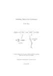
Visualizing the Simple Pendulum Rod with Equivalent Ellipsoids
Consider the simple pendulum rod in “Visualize a Simple Machine” in the SimMechanics
Getting Started guide. You can open the model by entering mech_spen at the command
line.
1-7
1
Introducing Visualization and Animation
The rod length L = 1 m, and its radius r = 1 cm. The inertia tensor is
Ê I xx
Á
Á 0
Á
Ë 0
0
I yy
0
Ê 2
ˆ
0
0
0 ˆ Á mr 2
˜
˜
˜
0 ˜=Á 0
mL2 12
0
Á
˜
˜
I zz ¯ Á 0
0
mL2 12 ˜
Ë
¯
Because the rod has an axis of symmetry, the x-axis in this case, two of its three principal
moments are equal: Iyy = Izz, and two of its three generalized radii are equal: ay = az. The
rod is a symmetric top and, since r is much smaller than L, its equivalent ellipsoid is
almost a line of zero volume and area.
The generalized radii of the equivalent ellipsoid are ax =
=
5 ( r 2)
5 3 ( L 2)
= 0.646 m and ay = az
= 1.12 cm. This is the rod so displayed:
Standard Body Geometry: Convex Hulls
Every Body has at least one Body coordinate system (CS) at the CG. A Body also has
one or more extra Body CSs for the attached Joints, as well as possible Actuators and
1-8
About Body Color and Geometry
Sensors. Each Body CS has an origin point, and the collection of all these points, in
general, defines a volume in space. The minimum outward-bending surface enclosing
such a volume is the convex hull of the Body CSs, and this is the alternative standard
body geometry. The SimMechanics convex hull excludes the CG CS.
To enclose a nonzero volume, this set must have at least four non-coplanar Body CSs.
Three non-collinear Body CSs are displayed instead by a triangle, and two non-coincident
origins by a line. One origin is displayed just as a point.
Four or more coplanar origins are displayed as a triangle, three or more collinear origins
are displayed as a line, and two or more coincident origins are displayed as a point.
Visualizing the Four-Cylinder Engine Crank with Convex Hulls
Open the four-cylinder engine model by entering mech_fceng at the command line. Start
visualization.
Open the Engine Block subsystem and note the Crank block representing the engine
crank. This Body block has five coplanar Body CSs, not including the CG CS. Visualize
the engine as convex hulls and click the Crank body, the largest body. The convex hull
forms a planar polygon.
1-9
1
Introducing Visualization and Animation
Custom Body Geometry and External Graphics Files
In place of the standard body geometry choices, you can provide a custom geometry
defined with external graphics files for one or more individual bodies. For more
information, see “Customizing Visualized Body Geometries”.
1-10
Hierarchy of Body, Machine, and Model Visualization Settings
Hierarchy of Body, Machine, and Model Visualization Settings
In this section...
“Visualized Geometries and Colors from Body Block Settings” on page 1-11
“Body Block Settings Affecting Body Visualization” on page 1-12
“Visualization Settings in the Machine and Model Hierarchy” on page 1-13
Visualized Geometries and Colors from Body Block Settings
The SimMechanics visualization window visualizes bodies represented by Body blocks in
your model. The visualization information that the window uses from the model comes
strictly from the mass, coordinate system, and visualization properties set individually in
each Body block's dialog.
Note: The window itself contains additional visualization controls that affect visualized
body geometries and colors.
1-11
1
Introducing Visualization and Animation
Body Block and Visualization Window Settings Control Body Visualization
Body Block Settings Affecting Body Visualization
How settings in Body block dialogs affect visualization depends on which type of body
geometry and which color you choose for a particular body. The Body dialog contains
three classes of such choices.
Mass Properties
The principal inertial moments and the mass of a body determine the size and shape of
its equivalent ellipsoid.
Body Coordinate Systems: Origins and Orientation
The relative positions of the Body's coordinate systems (CSs) determine the size and
shape of its convex hull.
Visualization
The color choice in the Body dialog's Visualization tab determines the color of the
visualized body.
1-12
Hierarchy of Body, Machine, and Model Visualization Settings
You make the choice of convex hull or equivalent ellipsoid to visualize an individual body
in the Body dialog's Visualization tab.
If you choose a custom body geometry for a Body, the external body geometry file
referenced in the Body dialog's Visualization tab determines the visualized body's size
and shape.
Note: The choice of standard or custom body geometry has no effect on the visualized
body's color. The choice of body color has no effect on the visualized body's geometry.
Visualization Settings in the Machine and Model Hierarchy
SimMechanics models start with initial default visualization settings. A model and
machines within the model also possess, respectively, model-wide and machine-wide
default visualization settings. Visualization settings are inherited from the highest
level (model) through machines to individual Bodies. You can change these default and
inherited settings.
1-13
1
Introducing Visualization and Animation
Inheritance Hierarchy of Default Visualization Settings
Initial Default Settings for a Model
The initial default visualization settings for an entire model are:
• Model-wide default body color: red (RGB value of [1 0 0])
• Model-wide default body geometry: convex hull
Machine Inheritance of Model-Wide Default Settings
The initial default visualization settings for a machine are:
1-14
Hierarchy of Body, Machine, and Model Visualization Settings
• Machine-wide default body color: inherit model-wide default
• Machine-wide default body geometry: inherit model-wide default
Body Inheritance of Machine-Wide Default Settings
The initial default visualization settings for a Body are:
• Default Body color: inherit machine-wide default
• Default Body geometry: inherit machine-wide default
1-15
2
Getting Started with the Visualization
Window
The SimMechanics visualization window allows you to control how you view your model's
bodies in both static display and dynamic simulation-based animation. It also allows you
to record animations.
• “Introducing the SimMechanics Visualization Window” on page 2-2
• “Controlling Body and Body Component Display” on page 2-6
• “Adjusting the Camera View” on page 2-9
• “Communicating with the Model from the Visualization Window” on page 2-16
• “Controlling Simulation from the Visualization Window” on page 2-20
• “Controlling Animation” on page 2-22
• “Recording Animation” on page 2-27
• “SimMechanics Visualization Menus and Their Controls” on page 2-32
2
Getting Started with the Visualization Window
Introducing the SimMechanics Visualization Window
In this section...
“About the Visualization Window” on page 2-2
“Opening and Updating the Visualization Window” on page 2-2
“Visualization Toolbar and Its Controls” on page 2-4
About the Visualization Window
The visualization window is an integral part of SimMechanics software. With it, you can
visualize your machines using a comprehensive set of display controls, interact with your
model, and watch and record animations.
The window uses a distinctive set of symbols and shapes to display bodies and Body
coordinate systems (CSs). This section is an overview of what you can do with the
SimMechanics window.
Caution The SimMechanics visualization window resembles a MATLAB® Graphics figure
window. But it is not a feature of MATLAB and has no figure handle.
Opening and Updating the Visualization Window
Starting visualization and choosing the default display options are discussed in “About
SimMechanics Visualization”.
• Once you configure your SimMechanics model for visualization, select Update
Diagram from the model's Edit menu (or press Ctrl+D).
The window opens and displays the machines in your model that you have chosen to
visualize. One window displays all selected machines simultaneously.
• To synchronize the static visualization display with your model, reselect Update
Diagram at any time.
This figure shows a model with the default background color.
2-2
Introducing the SimMechanics Visualization Window
SimMechanics Visualization Window Displaying a Four-Cylinder Engine (Isometric View)
Menu Bar Versus Toolbar Controls
Once you open the visualization window, you have two ways to control the display and
carry out these tasks:
• Use the buttons in the toolbar. Every feature on this toolbar occurs in the menus,
although the reverse is not true. See “Visualization Toolbar and Its Controls”.
• Use the menus in the menu bar. The menu contains specialized items and submenus.
See “SimMechanics Visualization Menus and Their Controls”.
2-3
2
Getting Started with the Visualization Window
Note: Changing the display settings using the visualization window controls changes
only your immediate view in the display window. By itself, it does not change the
visualization settings in the model.
If you want to save a change in the visualization window settings to the model, and thus
change the model's visualization settings, see “Communicating with the Model from the
Visualization Window”.
Visualization Toolbar and Its Controls
You can activate or change most visualization features by selecting buttons on the
window toolbar, instead of selecting items from the menus. The setting changes initiated
by the toolbar are the same as the corresponding menu actions: either you activate a
feature, enable or disable a feature, or initiate an immediate action.
Hovering your mouse cursor over a toolbar button displays the button's tooltip indicating
its function.
SimMechanics Toolbar Buttons
Toolbar Relationship to the Menus
You can access all of the toolbar functions in the menus as an alternative. The toolbar
reproduces most of the menu functions.
2-4
Introducing the SimMechanics Visualization Window
See “SimMechanics Visualization Menus and Their Controls” for a complete overview of
the visualization window controls.
2-5
2
Getting Started with the Visualization Window
Controlling Body and Body Component Display
In this section...
“About Body and Body Component Display” on page 2-6
“Interpreting the Body Display Symbols and Shapes” on page 2-6
“Changing Body Display Symbols” on page 2-7
“Changing Body Display Shapes” on page 2-7
About Body and Body Component Display
You can change how bodies look in the SimMechanics visualization window. This section
explains how to control body and body component display.
Interpreting the Body Display Symbols and Shapes
When a visualization window opens, it uses distinctive conventions to display the bodies
of your model.
Body Component Display
Body components are displayed with two distinctive symbols:
• The center of gravity (CG) point of each body is marked by a half-filled circle-plus
symbol
.
• Each Body coordinate system (CS) is marked by coordinate axis triads. The color
coding is X-Y-Z axes = RGB = red-green-blue.
Body Surface Display
The window displays all the bodies of every machine with visualization enabled. The
entire body surface is shaded with the color you choose for it. Its shape is one of these:
2-6
Controlling Body and Body Component Display
• Convex hull: a line, one or more joined surface patches, or a closed surface enclosing a
volume
• Equivalent ellipsoid
• A custom shape
Changing Body Display Symbols
You can turn off the CS triads, the CG symbols, or both using the toolbar, with the
Display Centers of Gravity and Display Coordinate Systems buttons.
You can activate or deactivate each button separately. The default for both is active.
Four-Cylinder Engine: Cylinder Piston With and Without Body CS Triads and CGs (Detail)
Changing Body Display Shapes
You can switch among three possible display shape options using the toolbar. They are
mutually exclusive; one is always active.
• Clicking the Set Body Geometries to Convex Hulls button displays all bodies as
convex hulls, regardless of the visualization settings in the Body blocks in the model.
• Clicking the Set Body Geometries to Ellipsoids button displays all bodies as
convex hulls, regardless of the visualization settings in the Body blocks in the model.
• Clicking the Set Body Geometries to Individual Body Settings button displays
each body according to the visualization settings in its Body block in the model. This
is the default.
2-7
2
Getting Started with the Visualization Window
Stewart Platform: Bodies Displayed as Convex Hulls and as Equivalent Ellipsoids
2-8
Adjusting the Camera View
Adjusting the Camera View
In this section...
“Setting the Background Color” on page 2-9
“Interpreting the Camera Projection, Field of View, and Viewpoint” on page 2-9
“Automatically Sizing the Camera Field of View” on page 2-11
“Automatically Setting a Camera Viewpoint” on page 2-12
“Actively Controlling the Camera Viewpoint” on page 2-13
“Camera Viewpoint and Mouse Controls” on page 2-14
Setting the Background Color
You must use the menu bar to change the background color of the display window within
the SimMechanics visualization window.
1
Open View, then select Change Background Color. A color palette opens.
2
Select a color. Click OK to implement your choice. The background color changes
immediately.
The color palette for the background is the same as the palette for custom body color. See
“Customizing Visualized Body Colors”.
Interpreting the Camera Projection, Field of View, and Viewpoint
To properly interpret what you see in visualization, imagine that the display window
shows the field of view of a camera. The properties of this virtual camera determine most
of what you need to know about controlling your view of the model's machines.
2-9
2
Getting Started with the Visualization Window
Visualization Window Camera Field and Visualized Scene
Visualization and Orthographic Projection
The visualization window uses orthographic (parallel) projection to reduce a threedimensional scene to two dimensions on your screen. That is, parallel lines of view
representing depth converge to a point only at infinity. The window displays the scene
without finite perspective.
Camera Field of View, Viewpoint, and Frame Size
The field of view is what you see within the virtual camera frame. The virtual camera's
viewpoint is the point and direction from which it views the scene. The virtual camera
frame has a size or aperture.
2-10
Adjusting the Camera View
Zooming
Changing the camera frame size or aperture, then shrinking or expanding the overall
size of the machines, is the equivalent of zooming in or out. The camera cannot zoom
directly, because there is no point of convergence or perspective.
Panning
Panning changes the camera's virtual location without changing its direction of view. It
means moving the camera frame horizontally or vertically in a constant virtual plane,
maintaining the orientation of the camera frame.
Rotating
Rotating means viewing the scene from a different direction, while maintaining a
constant zoom (effective distance from the machines).
A rotation rotates about the center of the geometric bounding box containing all the
objects in the field of view. (This geometric center is unrelated to body properties, such
as Body coordinate systems or centers of gravity.) The viewpoint is moved to another
point on the virtual sphere with this same geometric center. The view direction changes
to maintain the geometric center at the center of the display window.
World Coordinate System Axes Indicate Orientation Only
The World CS axis triad always appears at the lower-left corner of the display window.
The directions of the axes indicate orientation only. The position of the axes does not, in
general, indicate the position of the World coordinate system (CS) origin.
Automatically Sizing the Camera Field of View
You can automatically resize the camera's field or aperture size to fit all the visualized
objects. This step is equivalent to an automatic zoom. It does not rotate the viewpoint or
pan the camera.
To fit the field of view to size, click the Fit to View button on the toolbar. The camera
field resizes itself immediately.
2-11
2
Getting Started with the Visualization Window
Automatically Setting a Camera Viewpoint
You can automatically change your viewpoint of the visualized bodies by clicking one of
the six viewpoint buttons on the toolbar. The action applies immediately.
Clicking these buttons is equivalent to setting a plane of view defined by the World
CS axes. Except for the isometric view, these predefined viewpoints always have one
axis perpendicular to the plane of view (pointing into or out of the plane of view). The
isometric view is a viewpoint direction with equal direction cosines (all 1 / 3 ).
The default is the front view, with X pointing right, Y pointing up, and Z pointing out of
the plane of view.
2-12
Toolbar Button
Axes and Orientation of View Plane
Front View (default)
X points right – Y points up
Back View
X points left – Y points up
Top View
X points right – Z points down
Bottom View
X points right – Z points up
Adjusting the Camera View
Toolbar Button
Axes and Orientation of View Plane
Left View
Z points right – Y points up
Right View
Z points left – Y points up
Isometric View
X points down and right – Y points up – Z points down and
left
Actively Controlling the Camera Viewpoint
The four selection-viewpoint toolbar control buttons enable certain interactions between
your mouse and the display window through point-and-click or point-click-hold-and-roll.
These four toolbar-menu controls are mutually exclusive; you can activate at most one of
them at a time. The default is for the Select Tool to be active.
• Enable a tool by clicking on its button.
• Disable all of them by clicking the currently active tool button.
Function
Tool
How to Use
Select bodies Select
(default)
Point with the mouse at a visualized body, then click on any
mouse button.
Viewpoint
controls
Point with the mouse anywhere in display window. Then leftclick, holding the mouse button, and roll mouse.
Rotate
Pan
Zoom
Results of Rolling the Mouse with the Viewpoint Controls
With one of the three viewpoint control tools enabled, rolling the mouse produces one of
three possible results in the display window.
Rotate Tool
Rolling so that the arrow moves in the display window along a line, rotates the view
about that line. Rolling in a more complex figure rotates the view in a more complex way.
Pan Tool
Rolling forward, back, left, or right pans up, down, left, or right, respectively.
2-13
2
Getting Started with the Visualization Window
Zoom Tool
Rolling forward or back zooms out or in, respectively. You zoom toward or away from the
point that you initially clicked on. Rolling left or right does nothing.
For More About the Select Tool
See “Highlighting Bodies, Body Components, and Body Blocks”.
Camera Viewpoint and Mouse Controls
The four selection-viewpoint tool controls and the computer mouse have a
complementary relationship to each other.
Normal Versus Dynamic Mouse Control
In normal mouse control, the left mouse button's function corresponds to the function
activated in the menus or toolbar. Depending on which function you activate from the
menu or toolbar, you can switch the left mouse button from normal to dynamic mouse
control and back. “Actively Controlling the Camera Viewpoint” explains this case.
In dynamic mouse control, the viewpoint controls are disabled from the menu or toolbar.
(Either the Select Tool is enabled, or all four selection-viewpoint controls are disabled
from the menu or toolbar.) You can still exercise the viewpoint controls with the three
mouse buttons, which are mapped one-to-one to the viewpoint controls.
Note: If your mouse has fewer than three buttons, you cannot access the dynamic mouse
control functions associated with the missing button or buttons.
Normal and Dynamic Mouse Control with Left Mouse Button
The left mouse button's mapping is more complex.
Viewpoint
Control
Active
Normal:
Pan
If Pan Tool is
Pan field of view by clicking and holding anywhere in display
enabled from
window and rolling mouse.
menu or toolbar
2-14
How to Use
Adjusting the Camera View
Viewpoint
Control
Active
How to Use
Normal:
Zoom
If Zoom Tool is Zoom field of view by clicking and holding anywhere in display
enabled from
window and rolling mouse.
menu or toolbar
Dynamic:
Rotate
If Pan and
Zoom Tools are
disabled from
menu or toolbar
If Select Tool is
Rotate viewpoint by clicking and holding
disabled from menu anywhere in display window and rolling
or toolbar:
mouse.
If Select Tool is
Rotate viewpoint by clicking and holding on
enabled from menu only background in display window and rolling
or toolbar:
mouse.
Clicking on a visualized body in this case
selects the body and has no effect on
viewpoint.
Dynamic Mouse Control with Center and Right Mouse Buttons
The center and right mouse buttons' mappings are always dynamic.
Mouse
Button
Viewpoint
Control
Active
How to Use
Center
Dynamic: Pan If Select Tool is
Pan field of view by clicking and holding anywhere
disabled from menu in display window and rolling mouse.
or toolbar:
If Select Tool is
Pan field of view by clicking and holding on only
enabled from menu background in display window and rolling mouse.
or toolbar:
Clicking on a visualized body in this case selects
the body and has no effect on field of view.
Right
Dynamic:
Zoom
If Select Tool is
Zoom field of view by clicking and holding
disabled from menu anywhere in display window and rolling mouse.
or toolbar:
If Select Tool is
Zoom field of view by clicking and holding on only
enabled from menu background in display window and rolling mouse.
or toolbar:
Clicking on a visualized body in this case selects
the body and has no effect on field of view.
2-15
2
Getting Started with the Visualization Window
Communicating with the Model from the Visualization Window
In this section...
“Highlighting Bodies, Body Components, and Body Blocks” on page 2-16
“Updating the Model Diagram” on page 2-17
“Saving Visualization Settings to the Model” on page 2-18
Highlighting Bodies, Body Components, and Body Blocks
If you have the Select Tool enabled, clicking a body, Body coordinate system (CS), or
Body center of gravity (CG) in the SimMechanics visualization window causes the
following:
• The displayed body or body component changes color:
• A selected body surface or CS triad becomes yellow.
• A selected CG changes from white-black to yellow-black.
• The visualization window displays the associated Body block or Body CS name and its
path at the lower left just below the display window, in the status bar.
• The associated Body block is outlined in red in the model window.
To unhighlight, click the highlighted body again. You can select and highlight a body
both in static display and during simulation.
2-16
Communicating with the Model from the Visualization Window
SimMechanics Visualization Window with Highlighted Body and Body Block (Four-Cylinder Engine)
Enabling and Disabling Highlighting
You can enable or disable the highlighting of model Body blocks from the Model menu
item Enable Model Highlighting. The default is enabled.
Whether model highlighting is enabled or disabled, clicking a body or body component in
the window always highlights it. If you disable model highlighting, the associated Body
block is not highlighted when you click the displayed body or body component.
Updating the Model Diagram
You can update your Simulink model diagram from the model toolbar or Edit menu, or
by pressing Ctrl+D from the keyboard.
You can also update it by clicking the Update Simulink Diagram button in the
visualization window toolbar.
2-17
2
Getting Started with the Visualization Window
Saving Visualization Settings to the Model
As you work with the visualization settings, you might want to save the setting changes
that you make.
• Changes you make to the visualization settings apply only to the display while the
window is open. If you do nothing else and close the window, then upon reopening
the visualization window, the display will revert to whatever model requires for
visualization settings. See “Hierarchy of Body, Machine, and Model Visualization
Settings”.
• If you want to save the display setting changes you made from the window controls
before closing the window, you must save them to the model. Click the Save
Visualization Settings to Model button on the visualization window toolbar. A
warning dialog appears, asking if you want to save the model itself.
• If you want to save these display setting changes before closing the model, you must
save or resave the model itself. Click the Save button in the model toolbar.
2-18
Communicating with the Model from the Visualization Window
Caution If the changes to the display settings include changing the displayed body
geometries, the saved visualization settings will make the visualization window display
whatever the setting requires (all convex hulls, all equivalent ellipsoids, or individual
body geometries). But the saved visualization display settings do not change the
visualization settings at the model, machine, or Body block level in the model.
2-19
2
Getting Started with the Visualization Window
Controlling Simulation from the Visualization Window
In this section...
“Starting, Pausing, and Stopping the Simulation” on page 2-20
“Timing the Simulation” on page 2-20
Starting, Pausing, and Stopping the Simulation
You can control a simulation from the SimMechanics visualization window with the pair
of simulation control buttons. The pair takes two different appearances, depending on
whether the simulation is running.
With Simulation Stopped
From left to right, the buttons are Start and Stop, with Stop disabled:
.
With Simulation Running
From left to right, the buttons are Pause and Stop:
.
• If you pause a running simulation, restarting it begins the simulation at the
simulated time when it was stopped.
• If you stop a running simulation, restarting it begins the simulation at a simulated
time of zero.
Timing the Simulation
Once you start the simulation, you can track the simulation time at the lower right of the
visualization window, in the status bar, if the simulation time display is active.
2-20
Controlling Simulation from the Visualization Window
Simulation Time Display (Robot Arm Simulation with Visualized Body CSs and CGs Deactivated)
Activating and Deactivating the Simulation Time Display
You can activate or deactivate the simulation time display using the Display
Simulation Time button on the toolbar. The default is active.
2-21
2
Getting Started with the Visualization Window
Controlling Animation
In this section...
“About Animation” on page 2-22
“How Animation Works” on page 2-22
“Automatically Adapting the Camera View to the Displayed Motion” on page 2-23
“Changing How the Animation Is Updated” on page 2-24
“Speeding Up the Animation in Real Time” on page 2-25
About Animation
When you start a simulation with visualization and animation enabled, the
SimMechanics visualization window displays the body motion. This section shows how
you can control the animation.
How Animation Works
The visualization window displays the animated bodies in whatever camera view you
previously set before starting simulation. By default, the camera remains at rest in
World.
The animation that you see in the display window is the result of three distinct processes
operating in parallel.
• Simulink® updates the model simulation at every simulation time step.
• Simulink updates the model outputs at every output sample time step.
• During animation, the visualization window updates the display of the bodies at every
visualization sample time step.
Each updated, displayed simulation scene is also called a frame.
By default, the output sample times are every major time step, and the visualization
sample times are the output sample times. But, within limits, you can change the
relationships among these time steps.
Caution Because visualization needs the model outputs to update the animation, the
visualization sample time should be equal to or longer than the model output sample
2-22
Controlling Animation
time. If the visualization sample time is shorter, the displayed animation is updated at
the model output sample times.
Automatically Adapting the Camera View to the Displayed Motion
As the bodies move in the animation, the camera view you set for the static case before
simulation might not encompass their full range of motion. Or the bodies might move out
of the field of view altogether.
You can require the display window to adapt the field of view dynamically to the
animation with the Enable Automatic Expanding Fit and Enable Automatic Tight
Fit buttons on the toolbar. These buttons are mutually exclusive. The default for both is
disabled.
Allowing the Field of View to Expand with the Moving Bodies
If the animated bodies tend to move out of the field of view once, repeatedly, or
continually, click the Enable Automatic Expanding Fit button. The field of view will
then expand as necessary to encompass the geometric bounding box of all the bodies, as
visualized. The camera remains at rest in World.
Keeping the Field of View Limited to the Moving Bodies
If you want your field of view to encompass just the moving bodies and track them as
they move, click the Enable Automatic Tight Fit button. The center of the field of
view will remain fixed to the center of the geometric bounding box of all the bodies, as
visualized. The camera is no longer at rest in World, but continually zooms and pans to
track this geometric center.
Caution With automatic tight fit enabled, the observer's reference frame is no longer at
rest in World and, in general, is noninertial. The motion of bodies that you see is not that
seen by an observer in World.
This automatic tight fit can create the illusion that the bodies as a whole are not moving.
Disable the automatic tight fit to check if this is the case.
2-23
2
Getting Started with the Visualization Window
Changing How the Animation Is Updated
You might find it convenient to change how quickly the animation in the display window
responds to changes in the simulation, especially if the animation is going by too fast in
real (clock) time.
You can change most of these controls by going to the Simulation menu in the menu
bar, then to Control Animation Speed. The Animation Speed Control Parameters
dialog box opens. You can apply any changes and close the dialog by clicking OK.
Delaying the Simulation at Every Display Update
At each update of the animation display, the SimMechanics simulation is delayed for
some (simulated) time to allow you to follow the motion. You can change this delay
time in the Animation Speed Control Parameters dialog. Enter a nonnegative time (in
milliseconds) in the Delay per frame field. The default is 3 (ms).
Changing the Visualization Sample Time
You can break the default connection between visualization and model output sample
times in the Animation Speed Control Parameters dialog as well. Enter a specified
visualization sample time (in seconds) in the Visualization sample time field. This
time is simulated (not real) time.
The default is 0 (s). This is smaller than any positive model output sample time, and the
visualization is effectively updated at the output sample times.
Require the visualization explicitly to inherit the model output sample time by entering
-1.
Changing the Model Output Sample Time
You can also change the effective visualization sampling rate by changing the model
output sample time in the model's Configuration Parameters dialog and leaving the
visualization sample time to be whatever the model output sample time is. This time is
simulated (not real) time.
2-24
1
Open the Configuration Parameters dialog from the Simulation menu of your model
window.
2
On the Data Import/Export node, in the Save options area, change the Output
options pull-down menu entry to Produce specified output only.
Controlling Animation
3
Use the Output times field on the right to specify explicitly how often Simulink
should capture the simulation output. In this field, enter a vector of sample times.
The sample time range must be the same as or lie within the Start time and Stop
time range of the Simulation time area in the Solver node of Configuration
Parameters.
If you want a uniform output sampling, use the linspace command to specify the time
range and number of sample points:
linspace(start-time, end-time, number-of-points)
For example, to sample 200 points from 0 to 10 seconds:
1
Open Configuration Parameters from the Simulation menu.
2
Locate Output options in the Data Import/Export node. Change the pull-down
menu to Produce specified output only.
3
Enter linspace(0,10,200) in the Output times field. Click Apply or OK.
Tip This approach does change two distinct model features at once. Changing the
visualization sample time by itself (preceding) has the advantage of letting you specify
the model output sample time separately.
See the Simulink documentation for more about model output sample time.
Speeding Up the Animation in Real Time
As the simulation animates the bodies' motions, it might slow down. You can make the
animation computationally less demanding with these measures.
Skipping Frames
By default, the animation displays every updated frame. But you can skip a fixed number
of frames between displayed frames.
From the Simulation menu, select Control Animation Speed. In the Animation Speed
Control Parameters dialog, change the Number of skipped frames per update field to
a positive integer to specify this number. The default is 0.
Using fewer sample points leads to a more disjointed animation, but a faster simulation
and a smaller recorded animation file.
2-25
2
Getting Started with the Visualization Window
Turning Off Visualization Features
You can speed up the animation if you turn off one or both of these symbols:
• Body centers of gravity (CGs)
• Body coordinate systems (CSs)
The preceding section, “Controlling Body and Body Component Display”, explains how to
control their display.
You can also speed up the animation by turning off the simulation time display. See the
preceding section, “Controlling Simulation from the Visualization Window”.
2-26
Recording Animation
Recording Animation
In this section...
“About Recording” on page 2-27
“How Recording Works” on page 2-27
“Recording Animations” on page 2-27
“Compressing Animation Recordings” on page 2-29
“Controlling the Size of the Recorded Animation” on page 2-30
“Playing Recordings of Animation” on page 2-30
About Recording
As the SimMechanics visualization window displays the body motion, you can capture
what you see as a recording and save it. This section explains how to record animations.
See the preceding section, “Controlling Animation”, for more about animation.
How Recording Works
If you record an animation, the recording captures each updated, displayed simulation
scene as a frame.
Whatever you see in the animated display window, is what the recording captures, as
closely as it can within the limitations of the format.
Recording Animations
When you record an animation from the window, it is stored as a file on your system in
Audio Video Interleave (AVI) format.
Caution Recording an animation overwrites any existing file with the same name as
the AVI file in the same folder. The AVI file write fails if a file of the same name that is
locked by another application exists in the same folder.
2-27
2
Getting Started with the Visualization Window
Activating and Controlling Animation Recording
• You can activate animation recording by clicking the Store Animation in AVI File
button on the toolbar. The default is deactivated.
If you activate, the AVI File Location file browser opens, as discussed next.
• You control recording settings using the Simulation menu.
Specifying the Name and folder of the Animation File
You can specify a location and name for your AVI file recording by selecting Choose
AVI File Location from the Simulation menu. If you activate recording, an AVI File
Location file browser opens and requires you to select a location and specify an AVI
name. The default AVI name for a model called modelname.mdl is modelname.avi, but
you can change this default name. Click Save to complete the AVI file specification.
When you activate recording, this AVI file name appears in the bottom middle of the full
visualization window, below the display, in the status bar.
If you cancel the file browser, the recording is canceled as well.
2-28
Recording Animation
How MATLAB Records the Animation
The simulation first records a MATLAB movie by capturing the display at every
visualization sample time step. Then, in the termination phase of your simulation, it
converts this movie to AVI format and stores it in the AVI file. A small AVI Conversion
window opens to indicate that conversion and storage are complete and to display the
path of the AVI file. Click OK to close this prompt.
Compressing Animation Recordings
You can reduce the size of your AVI file by compressing it. Select Compress AVI File to
activate this feature. The default is active.
2-29
2
Getting Started with the Visualization Window
Support Restrictions for Recording Compression
AVI compression is available only on the Windows® platform. MATLAB uses the Indeo 5
compression algorithm. You must have the corresponding video codec installed to
• Compress an animation while recording.
• Decompress and play back a compressed animation recording.
Check your operating system configuration for installed video codecs.
Caution You must have the Indeo 5 video codec installed to compress an animation
recording. If you do not have this codec installed, animation and recording proceed, but
with compression deactivated.
Controlling the Size of the Recorded Animation
Any technique that reduces the number of visualization samplings and updates reduces
the total stream of animated frames and the size of the recorded file. See “Controlling
Animation”.
Tip If MATLAB runs out of memory while recording an animation, you will receive a
warning. The simulation continues until completion, but recording is truncated at the
simulation time when memory was exhausted.
Use one of the techniques discussed to reduce the total stream of animated frames and
attempt the recording again. The simplest technique is to skip frames.
Playing Recordings of Animation
You need an AVI-compatible video player to view the recorded file. You can use the
internal MATLAB movie viewer or an external video player.
Caution You must have the Indeo 5 video codec installed to decompress and play back a
compressed animation recording.
2-30
Recording Animation
Matching Playback Speed to Simulation Speed
Your computer will play back an AVI animation recording at 15 frames per second of
real (clock) time, regardless of the simulation speed or visualization sample time during
recording.
To guarantee that the animation playback show the simulation in real (clock) time,
before recording, set:
• The model output sample time to be 1/15th of a second.
• The visualization sample time to be equal to or less than the model output sample
time.
See “Changing How the Animation Is Updated” for more about sample times.
2-31
2
Getting Started with the Visualization Window
SimMechanics Visualization Menus and Their Controls
In this section...
“About the Visualization Window Menus” on page 2-32
“View Menu” on page 2-33
“Simulation Menu” on page 2-34
“Model Menu” on page 2-36
“Help Menu” on page 2-37
About the Visualization Window Menus
The menus of the visualization window group similar functions and contain all
visualization functions.
Some menu items have a default setting. Others do not, as indicated by a “—” entry for
the default in the menu tables following.
Menu Group
Feature or Function
View
Change camera viewpoint or frame; manipulate camera view; change
background
Simulation
Control simulation; change dynamic camera response to animation;
record animations
Model
Change display of body components and geometries; change common
visualization-model features
Help
Get visualization help
Persistent Settings Versus Immediate Action
In most situations, all menu items are enabled in the sense that you can activate it. In
some conditions, a menu item can be disabled, and you cannot activate it.
Some menu items control a persistent setting and switch between active and not active;
for example, Enable Model Highlighting. By selecting the item, you either activate it,
and a check mark appears; or you deactivate it, and the check mark disappears.
Other menu items, when you select them, instead trigger an immediate action, for
example, Simulation > Start.
2-32
SimMechanics Visualization Menus and Their Controls
View Menu
This menu allows you to control two distinct visualization features, the camera viewpoint
and frame and the background color.
Menu Item
Function
Orientation submenu:
Front, Back, Top,
Bottom, Left, Right,
Isometric
Set camera viewpoint.
Front
One choice is always active, and the choices
are mutually exclusive.
Fit to View
Resize camera field to closely fit the bodies
as viewed.
Applies immediately.
Current Tool:
Enable mouse point-and-click tool.
—
The choices are mutually exclusive, and can
all be unselected (deactivated).
Default
—
Select
Select objects in the display window.
Selected
Rotate
Rotate camera viewpoint.
Unselected
Pan
Pan camera field laterally and vertically.
Unselected
Zoom
Zoom in and out of camera field.
Unselected
Open color palette to choose background
color.
—
Change Background
Color
2-33
2
Getting Started with the Visualization Window
Simulation Menu
This menu allows you to control the simulation, the dynamic camera field, and the
recording of the animation.
Menu Item
Function
Simulation Start
start,
pause, and
stop
Start simulation. Appears and enabled only —
when simulation is stopped.
Applies immediately. Keyboard equivalent
is Ctrl+T.
Pause
Pause simulation. Appears and enabled
only when simulation is running.
Applies immediately.
—
Stop
Stop simulation. Enabled only when
simulation is running.
Applies immediately. Keyboard equivalent
is Ctrl+T.
—
Enable adaptive dynamic camera field
during animation.
The choices are mutually exclusive, and can
all be unselected (deactivated).
Fixed camera field,
viewpoint, and zoom;
camera at rest in
World.
Dynamic camera field
2-34
Default
SimMechanics Visualization Menus and Their Controls
Menu Item
Function
Enable
Automatic
Tight Fit
Default
Enable automatic resizing and zooming of Unselected
camera field to keep moving bodies in fit-toview field at all simulation times.
Virtual camera moves with overall model
motion with respect to World.
Enable
Enable automatic expansion of camera
Unselected
field to keep moving bodies in field at all
Automatic
Expanding Fit simulation times.
Virtual camera remains at rest with respect
to World.
Store in AVI File
Record and save animation in AVI file.
Choose AVI File Location Choose nondefault location for AVI file.
Compress AVI File
Apply compression to saved AVI recording
of animation.
Unselected
Default location
for saved AVI file
is current working
MATLAB folder.
Selected
Control Animation Speed Opens Animation speed control parameters Visualization
0
dialog.
sample time (s)
Applies immediately.
Delay per frame 3
(ms)
Number of
skipped frames
per update
0
Display Simulation Time Show simulation time in lower-right corner Selected
of full window.
Start–Pause–Stop Menu During Simulation
During simulation, the start–pause–stop part of the Simulation menu looks like this:
2-35
2
Getting Started with the Visualization Window
Animation Speed Control Parameters Dialog
The Control Animation Speed menu item opens the Animation Speed Control
Parameters dialog:
See “Controlling Animation”.
Model Menu
This menu allows you to control the display of body geometries and body components, as
well as communicate from the visualization window to the model.
Menu Item
Function
Default
Body Geometries
submenu:
Set geometries of visualized bodies.
—
2-36
SimMechanics Visualization Menus and Their Controls
Menu Item
Function
One choice is always active, and the choices are
mutually exclusive.
Default
Convex Hulls
Visualize all bodies in window as convex hulls.
Unselected
Ellipsoids
Visualize all bodies in window as equivalent ellipsoids.
Unselected
Individual
Body Settings
Visualize all bodies in window according to their
respective Body block visualization settings.
Selected
Centers of Gravity
(CGs)
Display centers of gravity of all visualized bodies.
Selected
Coordinate Systems
(CSs)
Display all Body coordinate systems attached to all
visualized bodies.
Selected
Update Simulink
Diagram
Apply Update Diagram command to model. Applies
immediately.
Keyboard equivalent is Ctrl+D. Model equivalent is
Edit > Update Diagram.
—
Enable Model
Highlighting
Enable automatic Body block highlighting when
visualized body is selected in display window.
Selected
Save Visualization
Settings to Model
Save current state of visualization window controls to
model. Applies immediately.
(You need to save the model itself to save the settings
permanently.)
—
Help Menu
This menu allows you to get online help for the visualization window. Selecting Open
Visualization Help immediately opens the Help browser to the SimMechanics
visualization documentation.
2-37
3
Customizing Visualization and
Animation
You can customize the colors and geometries of visualized bodies in the SimMechanics
visualization window. Choice of colors is intrinsic to visualization. Specifying a custom
body geometry requires an external graphics file for each customized body.
As an alternative to the visualization window, you can also visualize your mechanical
system with virtual reality.
• “About Custom SimMechanics Visualization” on page 3-2
• “Customizing Visualized Body Colors” on page 3-4
• “Customizing Visualized Body Geometries” on page 3-7
• “Visualizing with a Virtual Reality Client” on page 3-12
• “Reference” on page 3-26
3
Customizing Visualization and Animation
About Custom SimMechanics Visualization
In this section...
“Customizing Visualization Settings” on page 3-2
“Creating an External Virtual Reality Client” on page 3-3
Customizing Visualization Settings
You can customize the way that SimMechanics visualization displays bodies, in terms of
their colors and geometry. The geometry is composed of the body's size and shape.
• You can adjust the body color on a model- or machine-wide basis, or on an individual
body basis.
• With an external graphics file referenced by a Body block, the visualization window
can visualize the body with whatever shape the graphics file specifies.
For more information about starting visualization for a SimMechanics model, review the
section Starting Visualization.
Model- and Machine-Wide Body Color and Geometry Controls
The model–machine–body hierarchy controls the model- and machine-default body colors
and geometries. See “Hierarchy of Body, Machine, and Model Visualization Settings”.
To control visualization settings for an entire model or machine, you need to revisit the
following two dialogs. These controls allow you to set a single default color and a single
default standard geometry for all the bodies in a model or in a machine.
• To set a model-wide default body color and geometry, use the Visualization area of
the SimMechanics node of the Configuration Parameters dialog.
3-2
About Custom SimMechanics Visualization
• To set machine-wide default body color and geometry, use the Visualization tab of
that machine's Machine Environment block dialog.
Creating an External Virtual Reality Client
You can bypass standard SimMechanics visualization by creating a virtual reality
world of your own design to visualize your model's bodies. You can then build a custom
interface from your model to the virtual world and animate its virtual bodies. See the
final section, “Visualizing with a Virtual Reality Client”.
3-3
3
Customizing Visualization and Animation
Customizing Visualized Body Colors
In this section...
“Choosing Custom Body Colors” on page 3-4
“Switching Between Default and Custom Body Colors” on page 3-4
Choosing Custom Body Colors
SimMechanics visualization has two formats for specifying a color.
MATLAB ColorSpec Vector
You specify colors by RGB values according to the MATLAB Graphics ColorSpec for
• An entire model, in the Visualization area of the SimMechanics node of the
Configuration Parameters dialog.
• An entire machine, in the Visualization tab of that machine's Machine Environment
block dialog.
The RGB (red–green–blue) triple of values is a vector [r g b], with each value
separately satisfying 0 ≤ r, g, b ≤ 1.
• Red, green, and blue are [1 0 0], [0 1 0], and [0 0 1], respectively.
• Black and white are [0 0 0] and [1 1 1], respectively.
• Other valid triples specify nonfundamental colors.
Color Palette Interface
You specify colors for individual bodies by visual inspection in the color palette in their
respective Body dialogs.
Switching Between Default and Custom Body Colors
The SimMechanics visualization initial default color for visualized bodies is red (RGB of
[1 0 0]).
Changing the Default Color for All Bodies in a Model
You can change the initial default to a different default color for all visualized bodies in a
model.
3-4
Customizing Visualized Body Colors
1
Open the Configuration Parameters dialog, then go to the SimMechanics node.
2
In the Visualization area, change the Default body color RGB vector to a
different, valid vector of values.
3
Click Apply or OK.
Note: You can override the model-wide default body color, both for a whole machine and
for individual bodies.
Changing the Default Color for All Bodies in a Machine
The initial default is for a machine to inherit its model-wide body color. You can override
the initial default by specifying a different machine-wide default color for all the bodies
in one machine in your model.
1
Open that machine's Machine Environment block dialog and click its Visualization
tab.
2
In the Body color selection mode pull-down menu, choose Specify. The Default
body color field becomes active.
3
Change the RGB vector to a different, valid vector of values.
4
Click Apply or OK.
Note: You can override the machine-wide default body color for any individual body
within the machine.
Changing the Color of an Individual Body
The initial default is for a Body to inherit its machine-wide body color. You can override
the initial default by specifying a different color for an individual visualized body.
1
Open the Body block dialog and click its Visualization tab.
2
In the Body color pull-down menu, choose Use color palette. The color palette
button appears.
3
Click the color palette button. The color palette opens.
4
Select a color from the palette and click OK.
5
To save the changes to the Body block and the model, click OK on the Body dialog.
3-5
3
Customizing Visualization and Animation
Body Dialog: Visualization Tab and Body Color Palette
3-6
Customizing Visualized Body Geometries
Customizing Visualized Body Geometries
In this section...
“Choosing Custom Body Geometries” on page 3-7
“Switching Between Standard Body Geometries” on page 3-7
“About STL Body Graphics Files” on page 3-8
“Obtaining STL Body Graphics Files for Custom Body Geometries” on page 3-9
“Switching Between Standard and Custom Body Geometries” on page 3-10
Choosing Custom Body Geometries
Using body mass and geometry information from the Body block alone, the
SimMechanics visualization window allows you two choices of standard body geometry,
the convex hull and the equivalent ellipsoid.
You also have the choice of a nonstandard body geometry specified by an external
graphics file.
Switching Between Standard Body Geometries
The SimMechanics initial default body geometry for visualized bodies is the convex hull.
Changing the Default Geometry for All Bodies in a Model
You can change the initial default of convex hulls to equivalent ellipsoids for all
visualized bodies in a model.
1
Open the Configuration Parameters dialog, then go to the SimMechanics node.
2
In the Visualization area, select Equivalent ellipsoid from mass
properties from the Default body geometries pull-down menu.
3
Click Apply or OK.
Note: You can override the model-wide default body geometry, both for a whole machine
and for individual bodies.
3-7
3
Customizing Visualization and Animation
Changing the Default Geometry for All Bodies in a Machine
The initial default is for a to inherit its model-wide body geometry. You can override the
initial default by specifying a different machine-wide default geometry for all the bodies
in one machine in your model.
1
Open that machine's Machine Environment block dialog and click its Visualization
tab.
2
In the Default body geometries pull-down menu, choose a new machine-wide
default, either Convex hull from body CS locations or Equivalent
ellipsoid from mass properties.
3
Click Apply or OK.
Note: You can override the machine-wide default body geometry for any individual body
within the machine.
Changing the Geometry of an Individual Body
The initial default is for a Body to inherit its machine-wide body geometry. You can
override the initial default by specifying a different geometry for an individual visualized
body.
1
Open the Body block dialog and click its Visualization tab.
2
In the Body geometry pull-down menu, choose either Convex hull from body
CS locations or Equivalent ellipsoid from mass properties.
3
Click Apply or OK.
About STL Body Graphics Files
SimMechanics visualization supports the specification of body geometry (size and shape)
with stereolithographic (STL) files in either ASCII or binary format. Each body with a
custom geometry requires one STL file to provide this geometry.
Stereolithography specifies the three-dimensional surface geometry of a body by linked
triangles whose edges and vertices are oriented by the right-hand rule. The orientation
defines an “outside” and an “inside” of the surface. The edges and vertices of the
elementary triangles join to form a continuous surface. A closed surface of such linked
triangles approximates a body's smooth curved surface.
3-8
Customizing Visualized Body Geometries
Stereolithographic triangles have some similarity to convex hulls. But convex hulls are
directly and solely determined by the origins of the Body coordinate systems. Convex
hulls are not necessarily made up of triangles. An STL file can specify an arbitrary
number of elementary oriented triangles with vertices at arbitrary points in space. These
vertices have no necessary connection to the Body coordinate systems.
Obtaining STL Body Graphics Files for Custom Body Geometries
You can obtain STL body geometry files from a number of sources.
• You can write a new STL file as a text file, following the STL standard.
• You can generate an STL file from many mechanical design applications, such as
computer-aided design (CAD) platforms.
• The SimMechanics Link utility exports an STL file for each part in a CAD assembly.
The CAD platform must be linked to the SimMechanics Link utility.
• You can reuse existing STL files, possibly with your own modifications. You can
obtain such STL files from SimMechanics examples, other applications, and CADoriented Web sites.
Note: Refer to the SimMechanics Link documentation for more information about
exported STL files.
3-9
3
Customizing Visualization and Animation
Switching Between Standard and Custom Body Geometries
You can switch from the standard body geometries to a custom body geometry by
changing the Body block to reference an external body geometry file. This custom body
geometry specification overrides the model- and machine-wide defaults, but only for this
body.
Requirements for External Body Geometry Files
The external body geometry file must be in STL format.
Caution In order for custom visualization to work, this STL file must be either:
• On your MATLAB path.
• In your MATLAB present working folder.
• Specified with complete path in the Body dialog.
Otherwise, visualization reverts to the default body geometry.
Specifying an External Body Geometry File
1
Open the Body block dialog and click its Visualization tab.
2
In the Body geometry pull-down menu, choose External graphics file.
The External graphics file field and Attached to Body CS pull-menu appear.
3-10
3
Enter the graphics file name and any necessary path in the field.
4
From the pull-down menu, choose which Body CS to attach the graphics to. (The
Body CSs are listed in the Body's Position tab.) This Body CS serves as the
reference for the origin, coordinate axes, and units of the body geometry.
5
Click Apply or OK.
Customizing Visualized Body Geometries
Body Dialog: Visualization Tab and External Body Geometry Reference
Attached Body Coordinate System as Geometric Reference for the Body Geometry File
The external graphics file has no intrinsic geometric origin, orientation, or units. The
attached Body CS provides an origin, axis directions (orientation), and units of length to
interpret the geometric information specified by the external graphics file.
Tip If you need a body geometry origin, orientation, or system of units that is not
represented in your current list of Body coordinate systems, create a new Body CS in the
Position tab with the geometric features you want. You can make this Body CS invisible
on the Body block if you wish.
3-11
3
Customizing Visualization and Animation
Visualizing with a Virtual Reality Client
In this section...
“About Virtual Worlds for Machines and Models” on page 3-12
“Creating Virtual Worlds for SimMechanics Models” on page 3-12
“Interfacing SimMechanics Models with Virtual Worlds” on page 3-14
“Creating and Interfacing a Model Virtual World” on page 3-16
About Virtual Worlds for Machines and Models
You can bypass SimMechanics visualization and create a mechanical animation in a
virtual world of your own design. You create a virtual world, populate it with bodies
represented as virtual objects using Virtual Reality Modeling Language (VRML), then
interface the virtual world with your SimMechanics model. Creating your own virtual
animation requires a new or existing virtual world for your model and an interface
between them.
This section explains how to couple a separately created virtual world with a
SimMechanics model.
Building Virtual Worlds This section assumes that Simulink 3D Animation software is
installed on your system and that you are familiar with it and with creating virtual
worlds. Refer to the Simulink 3D Animation documentation for full details on installing
and using this toolbox.
We recommend you allocate generous central processor power, graphics card speed, and
memory for virtual reality visualization, especially for animation.
Creating Virtual Worlds for SimMechanics Models
The Simulink 3D Animation documentation and VRML books [1] explain how to create
virtual objects and assemble them into virtual worlds. A displayed virtual world is called
a virtual scene. The best way to become comfortable moving around in a virtual world
is to practice with a variety of movement modes and viewpoints. This section highlights
the requirements to make a virtual world usable as a visualization for a SimMechanics
model.
3-12
Visualizing with a Virtual Reality Client
Editing Virtual Worlds and VRML Files
As you create a virtual world populated by virtual bodies, you must create each
component body, then plan and implement the geometry of the bodies' initial state. Use
a VRML authoring tool that can read VRML as a native format to create and edit virtual
reality .wrl files. Simulink 3D Animation software includes a VRML authoring tool
called V-Realm Builder®. If you are familiar with native VRML source code, you can use
a plain text editor or the MATLAB editor to edit the files.
Representing Bodies as Virtual Objects
You represent each body by a virtual object encoded in a .wrl file. You also create a
master .wrl file to represent the virtual world that refers to body .wrl files, placing
and orienting these bodies in the larger scene. You can define a body's position and
orientation with respect to:
• The overall virtual world, corresponding to the SimMechanics coordinate system
World.
• Another body in the machine, corresponding to SimMechanics Body coordinate
systems.
You can nest body references to other bodies in VRML hierarchies, but you must define
at least one body's position and orientation with respect to the overall virtual world.
Place and orient the bodies in their initial states, corresponding with the initial state of
the SimMechanics simulation.
Each body's .wrl file contains a hierarchical tree starting with the Transform node.
Among Transform's fields must be translation and rotation fields to specify the body's
position and orientation in space. If a body is nested below another body, its position and
orientation are defined with respect to the next body up the hierarchy.
Creating your own virtual world gives you great flexibility in representing your machine:
• You can display bodies in as much or as little detail as you want, with shapes, colors,
textures, etc., of your own choosing.
• You can include or omit bodies as desired.
• You can create a computer-aided design (CAD) assembly of your machine and export
it into VRML files.
• If you only translate a body, you can omit the rotation field from its Transform node.
• If you only rotate a body, you can omit the translation field from its Transform node.
3-13
3
Customizing Visualization and Animation
Interfacing SimMechanics Models with Virtual Worlds
To animate a body, you need to measure its motion in your SimMechanics simulation
and export that information to the virtual world. This requires connecting Body Sensor
blocks to the Bodies you want to animate in your model, then creating an interface that
animates the virtual bodies with the body sensor motion signals. “Interfacing the Model
and the Virtual World” applies these steps to the mech_conveyor_vr example.
Adding and Configuring Body Sensors
Connect the Body Sensors to Body coordinate systems (CSs) on the bodies whose motions
you want to animate. The Body block reference discusses how to create and configure
Body CSs. You need to take these extra steps to export the signals of a body sensor to
your virtual world:
1
Make sure the Body Sensor's Body CS reference origin and orientation follow the
body's defining VRML hierarchy.
Example: You define a new Body CS on a body to connect the Body Sensor. If you
defined the VRML body's position with respect to the center of gravity (CG) of a
second, neighboring body in your VRML files, you should set the Translated from
origin of field of the new Body CS to the origin of the CG CS of the second body.
2
In the Body Sensor dialog, select the [x; y; z] Position check box if you want to
animate the body's translational motion.
Select the [3 x 3] Rotation matrix check box if you want to animate the body's
rotational motion.
3
Choose the coordinate system in which the body motions are measured in the With
respect to coordinate system pull-down menu. You can pick Absolute (World)
or Local (Body CS). This coordinate system should be the same as the coordinate
system used to define the body's position and orientation in the VRML files.
A Simulink output port > appears on the block for each of the motion signals. The
translational signal is a 3-vector of spatial coordinates, (x, y, z). The rotational signal is
a 9-vector, column-wise representation of the 3-by-3 orthogonal rotation matrix R, (R11,
R21, R31, R12, ...).
Animating the Virtual World Bodies
Animating the virtual bodies requires interfacing the body sensor signals in the
SimMechanics model with the VRML translation and/or rotation fields in the .wrl files.
3-14
Visualizing with a Virtual Reality Client
You accomplish this with the VR Sink block, which you can find in the Simulink 3D
Animation block library.
1
Enter vrlib at the command line. Drag a copy of the VR Sink block into your model.
2
Open the VR Sink dialog box. (The figure “Conveyor Loader Model: VR Sink Dialog
Box” displays an example of the dialog.)
3
In the Source file field in the World properties area, enter the name of the VRML
file that represents your model's virtual world. This is the file that refers to the other
.wrl files representing the component bodies of your machine. If the virtual world
VRML file is not in the same folder as your model, enter the file's path relative to the
model.
Click Apply. In the VRML Tree window, the node list of the virtual world .wrl file
appears.
4
Expand the tree of each component body in the list to view that body's check box
list. Select the rotation and/or translation check boxes as needed for each body.
A Simulink input port > appears on the block icon for each of these selected check
boxes.
The ports are labeled node.field. The node is the name for the body. The field is
named either rotation or translation.
Converting Body Sensor Signals into VRML Format
You are now ready to connect the Body Sensor output signals to the VR Sink block. But
you might need to modify those signals for valid use in VRML.
• You can connect the translational motion signal line directly from the output port of
the Body Sensor to the node.translation input port on the VR Sink. The VRML
node tree directly accepts translation motion as a 3-vector signal of rectangular
coordinates (x,y,z).
Make sure that the translational motion signal refers to the same coordinate system
used to define the body's position in the VRML files.
• You cannot directly connect the rotational motion signal line to the VR Sink. The
Body Sensor output represents orientation with a 3-by-3 rotation matrix R, while
VRML accepts orientation represented as the axis-angle 4-vector form [ n θ ], where n
= (nx, ny, nz) is a 3-vector representing the rotation axis and θ is the rotation angle.
Open the SimMechanics Utilities library. For each rotational motion signal, drag
a RotationMatrix2VR block into your model. Connect the rotation signal from the
3-15
3
Customizing Visualization and Animation
Body Sensor block to the RotationMatrix2VR block. Then connect the latter block to
the corresponding node.rotation input port on VR Sink for that body. This block
converts the 3-by-3 R matrix signal into the 4-vector VRML form.
Close the VR Sink block dialog. Your SimMechanics model now animates the virtual
world.
Creating and Interfacing a Model Virtual World
The model mech_conveyor_vr is a modified version of the original conveyor model
mech_conveyor.
Viewing the Custom External VRML Files
The mech_conveyor_vr model comes with external VRML files containing static
geometries of the machine parts in their initial positions. This example uses the V-Realm
Builder editor to view the files.
1
In the matlabroot\toolbox\physmod\mech\mechdemos\ folder, open these
external VRML files with V-Realm Builder:
base.wrl, convmech.wrl, link1.wrl, link2.wrl, link3.wrl,
link4.wrl, pusher.wrl
2
3-16
With the convmech.wrl world in focus, click the Test Mode button
in the VRealm Builder toolbar and view the complete machine in the Main view. Right-click
in this window to configure the navigation. If the colors seem washed out, disable the
headlight.
Visualizing with a Virtual Reality Client
3
On the left side of your VRML editor window, examine the node tree of
convmech.wrl that refers to the six VRML files representing each component body:
3-17
3
Customizing Visualization and Animation
The hierarchy of body position and orientation references is flat in this model. Each
body is separately referenced to the top level of the hierarchy, New World.
4
3-18
Expand one of the nodes. Each body node has, among others, rotation and
translation fields:
Visualizing with a Virtual Reality Client
The exception is the base. Being grounded and immobile, it has neither a translation
nor a rotation field.
Interfacing the Model and the Virtual World
In mech_conveyor_vr, open the Body Sensor1 block. The block measures the translational
and rotational motion of Link3 in the conveyor:
3-19
3
Customizing Visualization and Animation
The Body Sensor1 block has two Simulink output signals.
The other Body Sensor blocks are similar, except for Body Sensor2, which measures only
the translational motion of the pusher. All the Body Sensors measure body motions with
respect to World, the frame in which the conveyor base is at rest. Each motion signal
represents the body's displacement relative to its initial position.
The mech_conveyor_vr model contains a Simulink 3D Animation subsystem interfacing
to the model's custom VRML files.
3-20
Visualizing with a Virtual Reality Client
Conveyor Loader Model with Custom Virtual Reality Animation Interface
3-21
3
Customizing Visualization and Animation
Custom Virtual Reality Animation Interface Subsystem
3-22
1
Trace each body sensor signal. The signals are routed through pairs of Simulink Goto
blocks (in the model) and From blocks (in the custom library).
2
Open the Simulink 3D Animation subsystem, both by double-clicking its icon and by
looking under its mask. The VR Sink block, connected to From blocks transmitting
the body motion signals, and the virtual scene viewer appear. The conveyor loader
virtual scene is similar to that visible in the VRML editor (see “Viewing the Custom
External VRML Files”).
Visualizing with a Virtual Reality Client
Conveyor Loader Model: Simulink 3D AnimationViewer
3
From the menu bar of the virtual scene viewer, select Simulation, then Block
Parameters. The VR Sink block dialog opens.
The Source file is convmech.wrl, the master file for this virtual world. The
VRML Tree on the right reproduces the node tree visible in the VRML editor for
convmech.wrl.
3-23
3
Customizing Visualization and Animation
Conveyor Loader Model: VR Sink Dialog Box
4
Expand and scroll down the VRML trees. The trees for Link1, Link2, Link3, Link4,
and Pusher list the field inputs for accepting motion signals.
• The Link component bodies require both translational and rotational motions. All
the Links have actively selected check boxes for their rotation and translation
field inputs.
• The Pusher body requires only translational motion. Only the translation field
check box is selected for the Pusher.
3-24
Visualizing with a Virtual Reality Client
Each of the nine Simulink input ports on the VR Sink block is named node.field.
The Base of the conveyor does not move, so its node has no motion input fields.
5
If you closed the Simulink 3D Animation viewer, you can reopen it from the VR Sink
dialog. Click View in the World properties / Source file area of the dialog.
6
Close all the dialog boxes by clicking OK, leaving the viewer open.
7
Click the Start button in the model window.
As in the original mech_conveyor example, starting the model opens the Reference
Position slider bar that you can move from side to side. As you do so, watch the
pusher in the viewer move in parallel.
3-25
3
Customizing Visualization and Animation
Reference
[1] Marrin, C., and B. Campbell, Teach Yourself VRML 2 in 21 Days, Indianapolis,
Indiana, Sams, 1997.
3-26
4
Importing Mechanical Models
Using SimMechanics software with computer-aided design (CAD) extends your
mechanical modeling and simulation capabilities, allowing you to create SimMechanics
models from CAD assemblies. This chapter covers what you need to get started with CAD
translation. It assumes some familiarity with SimMechanics modeling.
• “Mechanical Import” on page 4-2
• “Generating New Models from Physical Modeling XML” on page 4-6
• “Working with Generated Models” on page 4-11
• “Model Update with Physical Modeling XML” on page 4-20
• “Controlling Model Update at the Block Level” on page 4-29
• “Troubleshooting Imported and Updated Models” on page 4-41
• “Import a CAD Rigid Body” on page 4-45
• “Import Robot Arm Model” on page 4-46
• “Import a CAD Stewart Platform Model” on page 4-50
4
Importing Mechanical Models
Mechanical Import
In this section...
“About Mechanical Import and CAD Translation” on page 4-2
“Requirements for CAD Export and Mechanical Import” on page 4-3
“Essential CAD Translation Steps” on page 4-4
About Mechanical Import and CAD Translation
SimMechanics software features an importer that lets you automatically generate
SimMechanics models from an XML file in Physical Modeling format. This externally
defined XML file specifies mechanical information — bodies, degrees of freedom, and
geometry — in a form that the SimMechanics importer can use to construct a model
representing that system.
The standard way to obtain such a Physical Modeling XML is to generate it by exporting
a computer-aided aided (CAD) assembly. CAD tools allow you to model mechanical
systems geometrically as collections of parts, or assemblies. You use Simulink and
SimMechanics block diagrams to represent control systems composed of mechanical
devices and simulate their dynamics. The block diagram approach does not include full
geometric information, nor do CAD assemblies typically incorporate controllers or allow
you to perform dynamic simulations. With CAD translation, you can combine the power
of CAD and SimMechanics software.
The SimMechanics Link utility is the necessary intermediary that lets you convert CAD
assemblies into SimMechanics models. The intermediate step between CAD assembly
and SimMechanics model is exporting an XML file in Physical Modeling format from
the assembly. The export also automatically creates STL files containing body geometry
information that you need for visualizing the bodies in the model.
The SimMechanics importer then converts this XML file into a mechanical model, which
references the STL files to visualize the bodies.
4-2
Mechanical Import
Complete Translation of CAD Assembly Into a Visualizable Model
Requirements for CAD Export and Mechanical Import
The full CAD translation is composed of two distinct steps, with different requirements.
1
The first step is the export of the CAD assembly, which creates the Physical
Modeling XML file and one or more STL file(s).
2
The second step is the import of the Physical Modeling XML file and generation of
the SimMechanics model.
CAD Export Software Requirements
To export a CAD assembly into XML, you must first
1
Install your CAD platform or software application.
2
Install the SimMechanics Link utility and link it to your CAD platform. The
SimMechanics Link utility requires MATLAB only.
Note: For CAD export, you do not need Simulink or SimMechanics software.
Setting Up SimMechanics Link Software
To install and register SimMechanics Link, see “Install and Register SimMechanics Link
Software”
Physical Modeling XML Import Software Requirements
To import a Physical Modeling XML file and generate a model, you must have installed
Simulink and the Simscape™ and SimMechanics products.
4-3
4
Importing Mechanical Models
Note: For XML import, you do not need a CAD platform or the SimMechanics Link
utility.
Essential CAD Translation Steps
Converting a CAD assembly to a SimMechanics model requires two major steps,
exporting the CAD assembly into XML, then importing the XML to create a
SimMechanics model.
Exporting an Assembly to XML
You export the assembly from the CAD platform into a Physical Modeling XML file
that you can later use with the SimMechanics importer. See the SimMechanics Link
documentation.
Exporting a CAD Assembly into a Physical Modeling XML File
Automatic Export of STL Files Representing CAD Part Geometries
When you export the CAD assembly into Physical Modeling XML, the SimMechanics
Link exporter also automatically creates an STL body geometry file for each body
represented as a CAD assembly part. You then need these STL files for SimMechanics
visualization, once you create your SimMechanics model.
See “Referencing STL Body Geometry Files for SimMechanics Model Visualization”.
Importing the XML and Generating a Model
To complete the CAD translation, you convert the Physical Modeling XML file into a
SimMechanics model. See “Generating New Models from Physical Modeling XML”.
4-4
Mechanical Import
Importing a Physical Modeling XML File into a Model
Referencing STL Body Geometry Files for SimMechanics Model Visualization
Once you have imported the Physical Modeling XML to create a SimMechanics
model, you can visualize the bodies in the model. The generated SimMechanics model
automatically references the necessary STL body geometry files, one for each body, to
visualize the bodies with their original CAD assembly shapes.
4-5
4
Importing Mechanical Models
Generating New Models from Physical Modeling XML
In this section...
“About Generated SimMechanics Models Based on CAD” on page 4-6
“Generating a New Model from a Physical Modeling XML File” on page 4-6
“Controlling New Model Import” on page 4-8
About Generated SimMechanics Models Based on CAD
Note: For complete information on exporting Physical Modeling XML, see the
SimMechanics Link documentation.
A computer-aided design (CAD) assembly can contain enough part and constraint
information that you can generate a SimMechanics model consisting of Body and Joint
blocks representing the assembly. Once you have exported a CAD assembly into a
Physical Modeling XML file, you can generate a SimMechanics block diagram model
from this file. A new generated model consists of a single SimMechanics machine,
corresponding to an assembly with a single root.
This section shows you how to import the XML file into a SimMechanics model using the
command mech_import, which constructs the model.
Requirements for Generating Models by Importing Physical Modeling XML
This section assumes that you have the SimMechanics product installed locally or
remotely, and that you have:
• The XML file representing a CAD assembly
• Optionally, STL body geometry files associated with the CAD parts
To generate the SimMechanics model, you do not need the CAD platform or assembly
from which the XML file was exported. You also do not need the SimMechanics Link
utility.
Generating a New Model from a Physical Modeling XML File
You generate the CAD-based SimMechanics model using the mech_import command or
dialog.
4-6
Generating New Models from Physical Modeling XML
Using the Command Line
To start the model generation from a hypothetical XML file called cad_assembly.xml,
enter
mech_import('cad_assembly.xml')
at the command line. A progress bar appears and is updated as the model is imported.
A Simulink model window opens. The model is populated by Bodies and Joints
corresponding to the assembly parts and constraints saved in cad_assembly.xml. The
name of the generated model is the name of the original assembly file, regardless of the
name chosen for the XML file.
Using the Import Dialog
You can also select a Physical Modeling XML file and generate a model from it through
the Import Physical Modeling XML dialog. Open it by entering mech_import at the
command line with no arguments. See the mech_import command reference for
complete information about the import dialog. After completing your settings, click OK to
start the import.
4-7
4
Importing Mechanical Models
Controlling New Model Import
You have several options for changing the default import behavior of mech_import and
the Import Physical Modeling XML dialog box. For more information, see “Nondefault
Features in Generated Models” on page 4-14.
Customizing the Generated Model Name
You can specify the name of the generated model in the mech_import command or the
import dialog. The default is to accept the assembly name specified in the XML file.
For example, an XML file called cad_assembly.xml could internally specify the
assembly name as CAD_Assembly. Generating a model from this XML file leads to a
model name of CAD_Assembly. But suppose you want to name it assembly1 instead.
Either:
• Enter at the command line
4-8
Generating New Models from Physical Modeling XML
mech_import('cad_assembly.xml','ModelToImportInto','assembly1')
This starts the import of cad_assembly.xml and creates a model file called
assembly1.mdl from it.
• In the dialog's Import tab, select the Specify model to import into check box. In
the Model name field, enter assembly1 and click OK.
Changing the Appearance and Layout of a Generated Model
The Advanced Options dialog tab displays model layout and block appearance controls
in the Layout area. With these, you can make your generated model easier to view and
understand. You can:
• Control how the importer names Joint blocks.
• Control the amount of space the importer creates between blocks.
• Control the direction in which the importer automatically adds blocks to the model.
You can alternatively use the equivalent options in the mech_import function.
Importing into a Subsystem
By default, the importer generates the model starting at the top level of model hierarchy.
It creates subsystems below that level if needed to translate subassemblies.
You can instead import the entire XML file into a subsystem, so that the top level of
model hierarchy is consists of just this subsystem. Subassemblies are then translated
into sub-subsystems below that level. If you import into a subsystem, you must specify
names for both the model and subsystem.
For example, you can import cad_assembly.xml into a subsystem called assembly,
residing in a new model called model_assembly. Either
• Enter at the command line
4-9
4
Importing Mechanical Models
mech_import('cad_assembly.xml', ...
'ModelToImportInto','model_assembly', ...
'SubsystemToImportInto','assembly')
This starts the import of cad_assembly.xml into the subsystem.
• In the dialog's Import tab,
• Select the Specify model to import into check box. In the Model name field,
enter model_assembly.
• Select the Specify subsystem to import into check box. In the Subsystem
name field, enter assembly and click OK.
Changing the Hierarchy of Moving Joints and Organization of Rigidly Connected Bodies
The Advanced Options dialog tab displays model simplification controls in the Model
simplification area. With these, you can isolate moving bodies and their DoFs from the
rest of the model. You can:
• Group Bodies rigidly connected by Welds into their own subsystems, each at the
appropriate subsystem level.
• Import non-Weld Joints at the highest level possible, depending on whether you
are importing a model or a subsystem, as well as group rigidly welded Bodies into
their own subsystems. The importer promotes moving Joints in the model hierarchy
regardless of where the corresponding degrees of freedom occur in the original
assembly.
You can alternatively use the equivalent options in the mech_import function.
4-10
Working with Generated Models
Working with Generated Models
In this section...
“About CAD-Based Models” on page 4-11
“Common Features of CAD-Based Models” on page 4-11
“Nondefault Features in Generated Models” on page 4-14
“Manually Modifying and Extending Generated Models After Import” on page 4-15
About CAD-Based Models
This section explores the characteristics of a generated CAD-based model, imported with
default or nondefault settings. It also explains when and how to edit your model and
expand it with additional blocks, such as Constraints, Drivers, Actuators, and Sensors.
The section concludes by pointing out major model-generation and simulation errors and
problems that can arise from CAD-based models, and techniques for solving them.
Common Features of CAD-Based Models
Note: This section assumes a model generated with default import settings and not
yet edited manually. To see the effects of using nondefault import settings in a newly
generated model, see “Nondefault Features in Generated Models” on page 4-14.
Most of the properties of models that you generate from an XML file are the same as the
default properties of all Simulink models. For information on working with Simulink
models, see the Simulink documentation.
SimMechanics models that are successfully generated from CAD-based Physical
Modeling XML have certain common properties that reflect their origin in CAD
assembles:
• Machine Environment, Ground, Body, and Joint blocks only.
• One Ground block and one connected Machine Environment block for each
SimMechanics machine.
• All other automatically generated SimMechanics blocks are Bodies and Joints
only, corresponding to the parts, degrees of freedom (DoFs), and constraints of the
Physical Modeling XML file imported.
4-11
4
Importing Mechanical Models
• The minimum Body coordinate systems and grounded coordinate systems necessary
to connect each Joint to exactly two coordinate systems, one on each side of the Joint.
• Unattached coordinate systems corresponding to reference coordinate systems in the
original assembly and, in general, not associated with constraints.
• Fundamental root, represented by Ground – Root Weld – Root Body. The Root Body
occurs at the top of the main hierarchy. The Root Body has no mass and no inertia,
and does not move.
• Subsystems below the top level encapsulating subassemblies from the original
assembly.
• Subassembly roots, represented by Root Body – Root Weld – Fixed Body. A Root Body
occurs at the top of each subsystem hierarchy if you need such a body to correctly
represent constraints in the original CAD assembly.
• Joints with DoFs containing the correct joint primitives for the translational and
rotational DoFs between any two bodies.
If no appropriate specific Joint exists, the importer inserts a Custom Joint with the
appropriate primitives.
• Joints without DoFs, represented by Welds.
• Apart from Root Body blocks, each Body block referencing its STL body geometry file.
• Both machine- and model-wide visualization enabled.
This is an example of a model generated from a robot arm assembly.
4-12
Working with Generated Models
World Coordinate System and the CAD Assembly Origin
A generated model has one Ground. The origin of this Ground is the origin of the World
coordinate system and represents the original CAD assembly origin.
SimMechanics Visualization and STL Body Geometry Files
Each body in a generated SimMechanics model, apart from the ground and root bodies, is
configured to reproduce the body geometry and color of its original CAD assembly body.
If the needed STL files were created upon export and are referenced by the generated
model, the custom body geometries are visualized. Each Body references its own STL file.
Caution In order for custom visualization to work, this STL file must be either:
• On your MATLAB path.
• In your MATLAB present working folder.
• Specified with complete path in the Body dialog.
Otherwise, visualization reverts to the default body geometry.
4-13
4
Importing Mechanical Models
For More About CAD Assemblies
Fully understanding the structure of a generated model requires understanding the
original system in its CAD representation. Refer to your originating CAD assembly, CAD
platform and associated documentation, and the SimMechanics Link documentation.
Nondefault Features in Generated Models
The importer controls allow generation of models with nondefault appearance and
structure. Optional, nondefault coordinate systems can enhance the fidelity and
usefulness of your models.
See “Controlling New Model Import” on page 4-8 and the mech_import function
reference page.
Nondefault Appearance and Layout of Generated Models
The following table summarizes the default and possible nondefault appearance options
of a newly imported model.
Default Appearance and Layout Options
Nondefault Appearance and Layout Options
Short Joint block names based on joint type
Potentially long Joint block names based on
model hierarchy
Block names that are potentially overlapping
Block names that do not overlap
Block diagrams first oriented horizontally from
left to right, then vertically from top to bottom
Block diagrams first oriented vertically from top
to bottom, then horizontally from left to right
Nondefault Hierarchy and Organization of Generated Models
The following table summarizes the default and nondefault hierarchy and organization
options of a newly imported model.
Aspect of Hierarchy & Default Hierarchy &
Organization
Organization
Nondefault Option A
Location of
non-Weld Joints
At the subsystem level
corresponding to the
subassembly level in the
original CAD assembly
At the highest level of the Same as default
model or subsystem being
imported
Grouping of Bodies
Ungrouped and located
individually at the
Grouped into their own
subsystem within the
4-14
Nondefault Option B
Same as nondefault
hierarchy A
Working with Generated Models
Aspect of Hierarchy &
Organization
rigidly connected by
Welds
Default Hierarchy &
Organization
subsystem level
corresponding to the
subassembly level in the
original CAD assembly
Nondefault Option A
Nondefault Option B
subsystem corresponding
to the subassembly level
in the original CAD
assembly
Coordinate Systems in Generated Models
In addition to the paired coordinate systems automatically generated for Body–Joint
connections, a generated model can contain other coordinate systems:
• Imported versions of reference coordinate systems in the original CAD assembly
that are not, in general, associated with CAD constraints. See “Inserting Reference
Coordinate Systems into Assemblies Before Export” on page 4-41. Upon import,
before manual modifications to the model, these Body coordinate systems are not
connected to other blocks.
• Coordinate systems manually added to the generated model after import. See “Adding
More Coordinate Systems” on page 4-17 .
Coordinate Systems: Automatically Generated, Inserted Before Export, and Manually Added After Import
Manually Modifying and Extending Generated Models After Import
A SimMechanics model satisfying full modeling requirements typically contains other
blocks beyond those generated by import. These blocks can include Constraints, Drivers,
4-15
4
Importing Mechanical Models
Sensors, and Actuators (from the SimMechanics block library), as well as blocks from
Simulink, such as Scopes. You manually insert and connect these additional blocks in
your generated model.
Tip When you first generate a model from Physical Modeling XML, you might want
to save this original CAD-based model before you create later versions by eliminating
unnecessary blocks and adding new ones.
Deleting Unnecessary Blocks
The constraint-to-joint mapping creates whatever blocks are needed to correctly isolate
the degrees of freedom (DoFs). In some models, certain generated blocks are not needed
for simulation. You can delete these unnecessary blocks to simplify your model without
affecting its dynamics, as long as you reconnect the remaining blocks properly.
In particular, you can simplify the fundamental root, Ground – Root Weld – Root Body,
in certain cases. (The same holds for subassembly roots. However, the corresponding
subsystem's Root Body takes the place of Ground, and the subsystem's Fixed Body plays
the role of Root Body.)
• If the Root Body is connected to the rest of the block diagram by a single Joint, you
can delete the Root Weld – Root Body blocks and reconnect the Joint directly to
Ground.
• If the Root Body is connected to the rest of the block diagram by multiple Joints, you
cannot delete the Root Weld – Root Body sequence because a Ground can connect
to only one Joint, and the generated model contains only one Ground. You have two
alternatives in this case:
• Determine where the Root Body coordinate systems (CSs) are. Delete the Root
Weld – Root Body sequence. Then manually add more Grounds at the spatial
points representing each of the deleted Root Body CS origins. Reconnect each Joint
to its corresponding Ground at the correct spatial point.
• Leave the Root Weld – Root Body sequence as it is.
Regrouping, Reducing, and Eliminating Welds
Not all Welds are redundant. Some Welds are needed to connect a Body that otherwise
would be isolated from the rest of the model. Such Welds represent rigid connections
between distinct assembly parts.
4-16
Working with Generated Models
• If you want to group Bodies rigidly connected by Welds into their own subsystems,
use the model hierarchy simplification controls in the Advanced Options tab of the
Import Physical Modeling XML dialog box or mech_import function.
• If you want to reduce or eliminate such Welds, return to your original assembly and
reexport it with rigid subassemblies. See the SimMechanics Link documentation.
Adding More Coordinate Systems
In addition to the automatically generated pairs of coordinate systems that connect
Joints representing CAD constraints, you can also add your own coordinate systems to
Bodies, after import. If you want to add Constraint, Driver, Actuator, or Sensor blocks to
a generated model, and connect these blocks to one or more of the Bodies, you need extra
Body coordinate systems as connection points.
These sections describe how to add Body coordinate systems to a Body:
• “Modeling Grounds and Bodies”
• “Working with Body Coordinate Systems”
Reference Coordinate Systems in the Original Assembly
You can also insert reference coordinate systems, in general not associated with
constraints, in the original assembly before export. You might find positioning and
orienting such coordinate systems easier in the CAD environment. Translation preserves
these coordinate systems, which appear in the generated model in addition to the
coordinate systems pairs connecting Joints and Bodies.
For more information, see “Inserting Reference Coordinate Systems into Assemblies
Before Export” on page 4-41.
Constraining and Driving Degrees of Freedom
Constraints reduce the number of independent degrees of freedom in a mechanical
system by preventing certain movements. Drivers affect DoFs, not by eliminating them
completely, but by forcing their motions to follow an external time-dependent signal. A
constrained or driven DoF is not free to respond to forces and torques independently.
These sections discuss how to add constraints and drivers to your model:
• “Constraining and Driving Degrees of Freedom”
• “Actuating a Driver”
4-17
4
Importing Mechanical Models
Note: You insert these constraints into the SimMechanics model as blocks. They act in
addition to the part constraints in the original CAD assembly.
Actuating Bodies and Joints with Motions and Forces
You can actuate bodies and joints in your SimMechanics models with external forces and
motions and set up internal forces between bodies. You can also vary the mass or inertia
(or both) of a body in time. Consult these sections for more details:
• “Actuating a Body”
• “Varying a Body's Mass and Inertia Tensor”
• “Actuating a Joint”
• “Adding Internal Forces”
Setting the Model's Initial Conditions
When you import a CAD assembly into the SimMechanics environment, the XML file
determines the initial geometric configuration of the model's bodies. By default, the
initial velocities of the bodies are zero, and the model is in .
If you want to change the initial positions and/or velocities of the bodies in your model
to be different from the CAD-determined configuration, you need to add initial condition
actuators, as discussed in “Specifying Initial Positions and Velocities”.
Sensing Forces and Motions
To detect the motions of bodies and joints and measure the forces acting on or through
them, you can add sensors to your model. See “Sensing Motions and Forces”.
Satisfying SimMechanics Model Validity Requirements
You can find the general instructions for building valid SimMechanics models in these
sections:
• “Representing Machines with Models”
• “Validating Mechanical Models”
Changing Custom Body Visualization Geometries and Colors
When it generates the Body blocks in a model (except for Root Bodies), the SimMechanics
importer automatically customizes the body geometries for visualization by referencing
4-18
Working with Generated Models
the STL files associated with the CAD assembly export. It also automatically customizes
the body colors to match the original CAD part colors, which are captured by the
exported XML file.
You can manually reset the custom visualization on one or more of these Bodies,
changing body shape, color, or both. See the Body block reference page and “About
Custom SimMechanics Visualization”.
4-19
4
Importing Mechanical Models
Model Update with Physical Modeling XML
In this section...
“About Model Update and Mechanical Import” on page 4-20
“Updating a Machine in a Generated Model with Revisions” on page 4-23
“Adding a New Machine to a Generated Model” on page 4-25
“Replacing Generated Model or Subsystem Contents with a New Machine” on page
4-27
About Model Update and Mechanical Import
Note: For the steps to generate a model by importing, see “Generating New Models from
Physical Modeling XML”.
For complete information on exporting Physical Modeling XML, see the SimMechanics
Link documentation.
The mech_import command and import dialog let you update models previously
generated from Physical Modeling XML. After revising the model's originating CAD
assembly, you export a new XML file representing the changed system. You can import
this new XML file to generate a new SimMechanics model, although you would have
to repeat on the new model whatever manual, post-translation work you did on the old
model.
4-20
Model Update with Physical Modeling XML
Translating a Revised CAD Assembly by Generating a New SimMechanics Model
But you can also update-import: import the new XML file to update the existing model.
Update-importing allows you to retain whatever manual, post-translation work you did
on the old model. You also keep any unchanged CAD-related features of the model.
Translating a Revised CAD Assembly by Updating an Existing Generated SimMechanics Model
4-21
4
Importing Mechanical Models
Updating by Subsystem, Machine, and Model
Update-import encompasses three distinct ways of revising a generated model with
revised assembly information. It revises by blocks within a machine, an entire machine,
an entire subsystem, or the entire model.
• Updating an existing machine in the model, which might include adding new blocks to
the machine
• Adding a new machine to the model
• Replacing model or subsystem contents with entirely new contents
Note: Update-import respects the model-machine-subsystem hierarchy of an existing
model. If you want to change this existing model hierarchy, you must manually edit the
generated model or generate a new model from your CAD assembly or XML file.
Requirements for Updating a Previously Generated Model by Importing Physical Modeling XML
This section assumes that you have the SimMechanics product installed locally or
remotely, and that you have:
• The XML file representing a revised CAD assembly
• The generated SimMechanics model you want to update
• Optionally, the STL body geometry files associated with the CAD assembly
To update-import the model, you do not need the CAD platform or assembly from which
the XML file was exported. You also do not need the SimMechanics Link utility.
Inheritance Relationships Between Assemblies and Models
See “Controlling Model Update at the Block Level” for a complete explanation of the
inherited structure and identity shared by assemblies and models based on them.
Controlling the Automatic Backup of Updated Models
Updating an existing generated model erases previous model information. But, by
default, the importer saves a copy of the previous version of the model through automatic
backup. You can control this automatic backup through the options in the mech_import
command or the import dialog. You can choose any one of these possibilities
4-22
Model Update with Physical Modeling XML
• Back up your previous model version in the same folder as the new version. This is
the default.
• Back up your previous model version in a different folder, which you specify.
• Do not back up your previous model version at all.
You can set these options through the Backup mode pull-down menu in the Backup
area of the Advanced Options tab of the import dialog.
Revisions to STL Body Geometry Files
Any revisions to an existing CAD assembly are reflected in the new set of exported STL
files that replace the old set of STL files from the earlier version of that assembly. Each
updated Body block continues to reference its corresponding STL file.
Updating a Machine in a Generated Model with Revisions
Revising a SimMechanics model previously generated from a CAD assembly means
that the importer translates changes to assembly part and constraint properties into
changes in Body and Joint properties. Depending on the nature of the assembly changes,
new blocks and connections can be added as well, and individual blocks can be replaced.
Property changes include changes to body mass properties and to body and grounded
coordinate system (CS) properties. Revising changes or extends only a single machine in
the model with revisions.
You start such an update-import with either
• The mech_import command; see the command reference page.
• The import dialog. On the Import tab, under Import mode, select Update existing
model. After configuring and applying the settings, click OK.
Using the two fields at the bottom of this tab, you can enter a nondefault model name,
and possibly a subsystem name, into which to import the revisions. The default is for
the importer to take the model and subsystem names from the XML file. In either
4-23
4
Importing Mechanical Models
case, the specified model, and possibly subsystem, must exist for the update-import to
succeed.
Controlling the Appearance and Hierarchy of an Updated Machine
An update-import can change the appearance of a generated machine. In both the
mech_import command and on the Advanced Options tab of the import dialog, you
can control how these changes occur. These controls are similar to the controls available
for importing a new model. See “Controlling New Model Import” on page 4-8.
• In the Layout area, you can require that the importer label new Joint blocks with
short names based on the Joint type.
• In the Update area, you can require the importer to:
• Find the best spatial arrangement of the blocks.
4-24
Model Update with Physical Modeling XML
• Import new Joint blocks at the highest level, depending on whether you are
importing into a model or a subsystem, and regardless of where the corresponding
degrees of freedom occur in the original assembly.
Controlling How Update-Import Changes Individual Blocks
In the Update area, you can use Respect individual block update settings to control
on a block-by-block basis how the importer changes blocks and their connections with
updates. Proper control of individual block updating requires understanding how a
generated model “remembers” its originating assembly. See “Controlling Model Update
at the Block Level” on page 4-29.
Adding a New Machine to a Generated Model
Adding a new machine to a SimMechanics model previously generated from a CAD
assembly means that the importer translates a completely new assembly into additional
Bodies, Joints, and subsystems. Such changes do not include updating existing machines
in the model.
You start such an update-import with either:
• The mech_import command; see the command reference page.
• The import dialog. On the Import tab, under Import mode, select Add to existing
model. After configuring and applying the settings, click OK.
Using the two fields at the bottom of this tab, you can enter a nondefault model name,
and possibly a subsystem name, into which to import the revisions. The default is for
4-25
4
Importing Mechanical Models
the importer to take the model and subsystem names from the XML file. In either
case, the specified model, and possibly subsystem, must exist for the update-import to
succeed.
If you are adding a new subsystem, select the Create new subsystem if it does not
exist check box.
Controlling the Appearance and Hierarchy of an Updated Model with an Added Machine
An update-import with an additional machine changes the appearance and hierarchy of a
model. In both the mech_import command and the Layout and Model Simplification
areas of the Advanced Options tab of the import dialog, you can control how these
additions occur, in the same way as if you were generating a new model. See “Controlling
New Model Import” on page 4-8.
4-26
Model Update with Physical Modeling XML
Replacing Generated Model or Subsystem Contents with a New Machine
Replacing model and subsystem contents in a SimMechanics model previously generated
from a CAD assembly means that the importer either:
• Completely erases the contents of the model at the top level and replaces these
contents with an entirely new machine.
• Completely erases the contents of a subsystem and replaces these contents with an
entirely new subsystem.
Warning Update-importing by replacement deletes the previous contents of the model
or subsystem. If you need to retrieve the old contents, use the model's backup copy. See
“Controlling the Automatic Backup of Updated Models”.
You start such an update-import with either:
• The mech_import command; see the command reference page.
• The import dialog. On the Import tab, under Import mode, select Import into
existing model (replace model or subsystem contents). After configuring and
applying the settings, click OK.
Using the two fields at the bottom of this tab, you can enter a nondefault model name,
and possibly a subsystem name, into which to import the revisions. The default is for
the importer to take the model and subsystem names from the XML file. In either
case, the specified model, and possibly subsystem, must exist for the update-import to
succeed.
4-27
4
Importing Mechanical Models
Controlling the Appearance and Hierarchy of an Updated Model or Subsystem with Replaced
Contents
An update-import with completely replaced contents changes the appearance and
hierarchy of a generated model or subsystem. In both the mech_import command and
the Layout and Model Simplification areas of the Advanced Options tab of the
import dialog, you can control how these additions occur, in the same way as if you were
generating a new model. See “Controlling New Model Import” on page 4-8.
4-28
Controlling Model Update at the Block Level
Controlling Model Update at the Block Level
In this section...
“Associativity and Updating” on page 4-29
“Working with Associativity in Common Updating Situations” on page 4-31
“Controlling How Update-Import Changes Individual Blocks and Connections” on page
4-34
“Associativity in an Updating Sequence Example” on page 4-37
Associativity and Updating
To update an existing generated SimMechanics model with changes to its original
external definition (a CAD assembly, for example), the intermediate Physical Modeling
XML file and the model itself must retain information about the identities of at least
some of its components. This section explains this “identity memory” or associativity.
What Is Associativity?
Associativity is a key concept for understanding the relationship between CAD
assemblies and SimMechanics models based on them, and the export and updating
process that defines SimMechanics models from CAD assemblies.
Associativity Between CAD Assemblies and SimMechanics Models
Associativity is a persistent (session-independent) parallel relationship among certain
components of a CAD assembly, Physical Modeling XML files exported from it, and
SimMechanics models generated from the XML files.
This relationship preserves the identities and parallelisms of certain CAD components
and the corresponding imported components of the SimMechanics model. The
SimMechanics Link exporter defines these unique identities from the CAD assembly
components and embeds them in the exported Physical Modeling XML file.
SimMechanics models generated from the XML file in turn retain these identities.
You actualize associativity when you generate a SimMechanics model from a CAD
assembly. Associativity is a mapping between parts, constraints, and subassemblies in
a CAD assembly and the corresponding Body and Joint blocks, coordinate systems, and
subsystems in the SimMechanics model generated from that CAD assembly. It uniquely
4-29
4
Importing Mechanical Models
captures the identities of these CAD components, their corresponding blocks, and their
topology (how they are connected to one another).
Associativity is not completely symmetric between the CAD and SimMechanics worlds,
because the translation process moves in one direction only, from CAD assembly to
generated SimMechanics model.
When and Why You Need Associativity
Associativity is required for updating a generated SimMechanics model when its
originating CAD assembly has been changed.
How Associativity Is Implemented
When you use the SimMechanics Link exporter to create a Physical Modeling XML file
from a CAD assembly, these components receive unique XML identifiers. When you use
the SimMechanics importer to generate a SimMechanics model from the XML file, the
identifiers are preserved in the corresponding SimMechanics model features.
Parallel Identities Between CAD Assembly and SimMechanics Model Components Captured by Associativity
CAD Assembly Components
Corresponding Imported SimMechanics Model
Components
Parts and grounds
Body and Ground blocks
Constraints between parts
(allowed motions)
Joint blocks
Constraints between parts
(positions and orientations)
Paired coordinate systems attached to Joints
Reference coordinate systems
Body coordinate systems unattached after import
Subassembly hierarchy
Subsystem hierarchy
Changing Assemblies, Generated Models, and Their Associativity
The associativity of CAD assembly and generated SimMechanics model is open,
modifiable, and extensible. As long as a generated SimMechanics model retains at
least one associated imported component, this model retains some associativity with its
originating CAD assembly.
Preserving associativity
You preserve the original associativity if you do not remove or reconnect associated
components in either the CAD assembly or the SimMechanics model.
4-30
Controlling Model Update at the Block Level
Changing the properties of an associated component, without removing or reconnecting
it, both uses and preserves associativity.
Extending associativity
You extend the original associativity if you add new, associable components to the CAD
assembly, export the assembly, and update-import the generated SimMechanics model.
The new components generated in the updated SimMechanics model are associated with
the new components of the CAD assembly.
Modifying associativity
You modify the original associativity if you remove or reconnect one or more associated
components in the SimMechanics model.
• The associativity of the removed or reconnected associated components is destroyed.
• The associativity of the other associated components, and of the SimMechanics model
as a whole, remains intact.
• You recreate the original associativity of the removed or reconnected components in
the SimMechanics model if you reimport the unchanged components from the CAD
assembly.
You can prevent this reimportation of the original CAD assembly components and
overwriting of your manual changes to a SimMechanics model, depending on your
import settings. See “Working with Associativity in Common Updating Situations”.
Replacing associativity
You replace the original associativity if you remove or reconnect one or more associated
components in the CAD assembly.
Once you export the CAD assembly and update-import the SimMechanics model, the
associativity of the removed or reconnected components is destroyed. In this case, the
component is either connected in a new way, with a new associativity, or it is removed
altogether.
Working with Associativity in Common Updating Situations
The unique parallel identities created by associativity allow you to revise and
expand CAD assemblies, then export the changed CAD assemblies and update
existing SimMechanics models based on them. While you can also create entirely new
4-31
4
Importing Mechanical Models
SimMechanics models from the updated XML, associativity saves the effort invested in
editing and testing by reusing existing SimMechanics models.
The following translation cases cover the basic possibilities. You can combine some of
them into more complex, compound cases. For example, you can change a CAD assembly
by both revising existing component properties and adding new components.
You can also modify the import process by preventing or allowing certain automatic block
and block connection changes. See “Controlling How Update-Import Changes Individual
Blocks and Connections”.
Exporting a CAD Assembly and Generating a SimMechanics Model for the First Time
During CAD export, SimMechanics Link assigns a unique XML identifier to each
CAD component. For a table summarizing the different CAD components, see “How
Associativity Is Implemented”.
When you import the XML file and generate a SimMechanics model from it, the
corresponding model components listed in the table's second column receive these
parallel identities.
Updating a Generated SimMechanics Model by Modifying CAD Assembly Properties
If you modify a CAD assembly and export a new Physical Modeling XML file from it,
updating the model with the modifications allows you to reuse an existing SimMechanics
model that was previously translated from the same assembly.
You modify a CAD assembly when you change the properties of its components without
changing their identity. For a table of CAD assembly components you can modify, see
“How Associativity Is Implemented”.
You update a generated SimMechanics model when you import the Physical Modeling
XML file for the modified CAD assembly. The updated model reflects the new component
properties in the modified assembly.
Associativity identifies the components in the existing generated SimMechanics model so
that the importer can update their properties.
Tip You can prevent the SimMechanics importer from updating one or more particular
associated blocks when you update-import a generated SimMechanics model. See
“Controlling How Update-Import Changes Individual Blocks and Connections”.
4-32
Controlling Model Update at the Block Level
Updating a Generated SimMechanics Model by Extending the CAD Assembly
If you add more components to a CAD assembly and export a new Physical Modeling
XML file from it, updating the model with the extensions allows you to reuse an existing
SimMechanics model previously translated from the same CAD assembly.
You extend a CAD assembly when you add one or more components to it. For a table of
CAD assembly components you can add, see “How Associativity Is Implemented”.
You update a generated SimMechanics model when you import the Physical Modeling
XML file for the extended CAD assembly. The updated model contains new blocks
representing the new components in the extended assembly. Blocks representing original
CAD components remain unchanged.
Associativity identifies the original components in the existing generated SimMechanics
model so that the importer does not change them while adding the new associated
components.
Modifying a Generated SimMechanics Model Associated with a CAD Assembly, Then Updating
Its Associated Components
You can also manually add nonassociated components to an existing SimMechanics
model previously generated from a CAD assembly, separately revise the assembly,
then retranslate the assembly by update-importing the SimMechanics model with the
revisions.
• The associated SimMechanics model components are updated with the CAD assembly
revisions.
• The nonassociated SimMechanics model components are not unchanged.
• If the nonassociated SimMechanics model components are connected in the original
model to associated blocks, they might become disconnected after update-import.
• Nonassociated model components can include Constraints, Drivers, Actuators, and
Sensors that you manually added and connected to associated, imported Bodies
and Joints.
• Nonassociated model components can also include Bodies and Joints added
manually after you generated the original SimMechanics model. These Bodies and
Joints were not import-generated and therefore cannot be associated.
Tip You can prevent the SimMechanics importer from updating associated blocks or
disconnecting nonassociated blocks from updated associated blocks when you update4-33
4
Importing Mechanical Models
import a generated SimMechanics model. See “Preserving and Breaking Connectivity of
Nonassociated Blocks to Updated Associated Blocks”.
Replacing Associated Joints with Nonassociated Joints in a Generated SimMechanics Model,
Then Updating the Model
You can manually delete an associated imported Joint and replace it with a
nonassociated Joint. This option is an important case of modifying and updating a
generated SimMechanics model.
1
Delete the associated imported Joint.
2
Add a replacement Joint manually. This Joint is not associated with the original
CAD assembly, because it was not imported.
However, the two Bodies on either side of the Joint and to which it is connected
are still associated, unless you also replace them. Thus the replacement Joint is a
nonassociated block connected to two associated blocks.
3
Update-import the modified SimMechanics model with changes to the originating
CAD assembly. Because it is not associated, the replacement Joint is not changed by
the update-import.
4
Fix any broken connections of the replacement Joint to the associated Bodies,
depending on the nature of the changes to the originating CAD assembly.
• You can allow the update-import to break these connections.
• But you can also require the update-import to preserve these connections. See
“Preserving and Breaking Connectivity of Nonassociated Blocks to Updated
Associated Blocks”.
If you replace the associated Bodies on either side of the Joint as well, then all
three blocks are now nonassociated. The update-import cannot change them or any
connections among them.
Controlling How Update-Import Changes Individual Blocks and
Connections
You can modify how the update-import process changes the updated model.
4-34
Controlling Model Update at the Block Level
Enabling and Disabling Automatic Update of Individual Associated Blocks
If you want to prevent the update-import process from updating or removing particular
blocks in a generated model, you can disable the updating or removal for individual
blocks. Doing this does not erase any associativity information from these blocks, and you
can reenable automatic updating as long as the block exists in the model.
To enable automatic updating for an individual associated block:
1
Right-click the block and select the SimMechanics menu item.
2
Clear Retain without updating properties. This is the default.
To disable automatic updating for an individual associated block:
1
Right-click the block and select the SimMechanics menu item.
2
Select Retain without updating properties.
Note: The right-click submenu item is available only on associated blocks. The default for
Retain without updating properties is cleared. That is, the default is that automatic
block updating is enabled.
Respecting and Overriding Associated Block Update Settings During Model Update-Import
You can override individual associated block update settings for the model update as a
whole.
4-35
4
Importing Mechanical Models
In the import dialog, you can specify whether the update-import respects or overrides
these individual block settings on the Advanced Options tab. (The mech_import
command allows you to set an equivalent option as a command input.)
• To require that the update-import respect the individual associated block update
settings, select the Respect individual block update settings check box. This is
the default.
• To override the individual associated block update settings, clear the Respect
individual block update settings check box.
Preserving and Breaking Connectivity of Nonassociated Blocks to Updated Associated Blocks
If you want the update-import to preserve the connections of individual nonassociated
blocks to associated blocks, you can enable connection preservation for individual blocks.
You can also allow the update-import to break such connections. Allowing connection
breaking does not remove the nonassociated block. You can reconnect it manually and
reenable connection preservation again as long as the block exists in the model.
To always preserve the connection of an individual nonassociated block from an updated
associated block:
4-36
1
Right-click the nonassociated block and select the SimMechanics menu item.
2
Select Retain connectivity to imported blocks. This is the default.
Controlling Model Update at the Block Level
To allow automatic disconnection of an individual nonassociated block from an updated
associated block:
1
Right-click the nonassociated block and select the SimMechanics menu item.
2
Clear Retain connectivity to imported blocks.
Note: The right-click submenu item is available only on nonassociated blocks connected
to associated imported blocks. The default for Retain connectivity to imported
blocks is selected. That is, the default is that automatic updating preserves the
nonassociated block's connection to associated blocks.
Associativity in an Updating Sequence Example
This example shows how associativity works and how you can use it in a simple threebody mechanical system translated from a CAD assembly to a SimMechanics model.
4-37
4
Importing Mechanical Models
The machine consists of three bodies connected in a chain. The first and second bodies
are constrained with one type of allowed motion. The second and third bodies are
constrained with another type of allowed motion.
Translating the Assembly and Generating the Model for the First Time
The initial translation from the CAD assembly results in a SimMechanics model with
three bodies (B1, B2, B3) connected in a chain by two joints (J1, J2). These associated
model components are the Body and Joint blocks and the Body Coordinate Systems (CSs)
that connect the Bodies through the Joints.
Revising an Assembly Body, Manually Adding Nonassociated Sensors in the Model, and
Updating the Model from the Assembly
The next step is to revise the assembly by changing some properties of one of the
assembly parts (P2). At the same time, you add two new, nonassociated components to
the generated model: a Joint Sensor (JS) and a Body Sensor (BS).
You then update-import the model from the revised assembly. The body properties
of B2 are updated. Assuming you keep the default settings, the connections of the
nonassociated Joint and Body Sensors to J1 and B3, respectively, are retained.
4-38
Controlling Model Update at the Block Level
Manually Replacing an Associated Model Joint and Updating the Model from the Assembly:
Update Options
The last step in the example is to manually replace one of the model joints (J2) with a
new, nonassociated Joint block (J3). If you update-import the model from the assembly
now, you must choose how to update the replaced joint J3:
• You can override the manual joint replacement.
The old joint J2 is reimported and re-replaces the manually inserted joint J3. This is
default setting on SimMechanics blocks.
• You can require that the manual changes be retained.
The newly added joint J3 is retained. This choice requires you to change the default
setting on the relevant SimMechanics blocks.
The import default is to respect the individual block settings in any case, although you
can change that as well.
4-39
4
Importing Mechanical Models
4-40
Troubleshooting Imported and Updated Models
Troubleshooting Imported and Updated Models
In this section...
“Best Practices for Creating and Exporting Assemblies” on page 4-41
“Inserting Reference Coordinate Systems into Assemblies Before Export” on page
4-41
“Controlling Mechanical Import to Assist Troubleshooting” on page 4-42
“Troubleshooting Errors During Model Generation” on page 4-42
“Troubleshooting Errors During Model Update” on page 4-43
“Troubleshooting Model Simulation Errors” on page 4-43
“Troubleshooting SimMechanics and Simulink Problems” on page 4-43
If your CAD assembly was not constructed or exported properly, you might encounter
problems in your generated SimMechanics model.
Best Practices for Creating and Exporting Assemblies
The SimMechanics Link documentation presents instructions and tips on these topics:
• Constructing a CAD assembly specifically for SimMechanics
• “Fixing” subassembly parts and subassembly roots
• Exporting a CAD assembly
• Identifying and fixing export errors
Inserting Reference Coordinate Systems into Assemblies Before Export
Translation might not place Body coordinate systems where you need them in the
imported model, to attach Joint, Constraint, Driver, Actuator, or Sensor blocks. If so,
insert reference coordinate systems into the CAD assembly at the appropriate positions
and orientations and re-export the assembly into an XML file for import. These preexport reference coordinate systems appear on the corresponding Body blocks after
import.
For more information, see:
• “Coordinate Systems in Generated Models” on page 4-15.
4-41
4
Importing Mechanical Models
• “Adding More Coordinate Systems” on page 4-17.
Note: Inserting and optionally exporting reference coordinate systems is not supported
for all CAD platforms supported by SimMechanics Link software.
Controlling Mechanical Import to Assist Troubleshooting
Both the Import Physical Modeling XML dialog box and the mech_import function have
model generation controls that can assist you in isolating errors in a newly imported
model. You can:
• Make the Joint blocks, the Body blocks rigidly connected by Welds, or both, in your
model easier to locate by using the model hierarchy simplification options.
• Make the Joint and other blocks easier to locate and identify by changing the model
layout options.
Troubleshooting Errors During Model Generation
Errors in the Physical Modeling XML file appear as warnings at the MATLAB command
line during model generation.
Identifying and Fixing Joint Translation Errors
Warnings arise from CAD constraint translation errors encountered when the XML
file was originally exported. Such errors occur when the translator fails to map one or
more CAD constraints, which restrict the degrees of freedom between parts, into their
corresponding SimMechanics joints. The exporter warns you at the export step if such
errors occur.
The failed Joint appears in your generated model as a Weld. You can fix such an error in
two ways:
• Return to the original CAD assembly, reconfigure the constraint, and export it again.
• In the generated model, manually replace this Weld with a proper moving Joint.
Tip If you need reference coordinate systems on Bodies to facilitate repairing
mistranslated Joints after import, see “Inserting Reference Coordinate Systems into
Assemblies Before Export” on page 4-41.
4-42
Troubleshooting Imported and Updated Models
Troubleshooting Errors During Model Update
Update-importing an existing generated model can produce the same types of errors as
importing a new model. The preceding discussion in this section explains these potential
errors and how to identify and fix them.
In addition, you might update-import an existing generated model in a way that is
technically correct, but not what you intended. To prevent such inadvertent errors,
review:
• “Model Update with Physical Modeling XML” on page 4-20
• “Controlling Model Update at the Block Level” on page 4-29
Troubleshooting Model Simulation Errors
Certain problems with CAD-based models appear only when you run the model.
• You must “fix” at least one part in every CAD subassembly by mating it to the
subassembly root. Otherwise, the massless root body is dynamically active and
experiences infinite acceleration when forces or torques are applied to it.
• If you find constraints are violated while your model is running, try the following:
• Examine your original CAD assembly for redundant constraints.
• Check and possibly increase the assembly tolerances at the original CAD export
step.
• Check and possibly increase the translated model's assembly tolerances in the
machine's Machine Environment block, in the Parameters tab.
• On the Constraints tab in the Machine Environment dialog, select the Use
robust singularity handling check box.
• Decrease the assembly tolerances at the original CAD export step.
Caution Never decrease assembly tolerances in a CAD-based SimMechanics model.
Instead, decrease them in the original assembly, then reexport.
Troubleshooting SimMechanics and Simulink Problems
You might also encounter general Simulink or SimMechanics problems while running
your model.
4-43
4
Importing Mechanical Models
• For SimMechanics problems, see “Troubleshooting Simulation Errors”.
• For general Simulink problems, consult the Simulink documentation.
4-44
Import a CAD Rigid Body
Import a CAD Rigid Body
This example shows you how to import a simple CAD assembly into SimMechanics. The
assembly is a simple cup with zero mechanical degrees of freedom. The example requires
export of the cup assembly from a supported CAD platform using SimMechanics Link.
For a step-by-step description of the export procedure, see “Export a CAD Rigid Body”.
To generate a model from a CAD assembly, you import the Physical Modeling XML file
that SimMechanics Link generates during CAD Export.
1
Move or copy the exported XML file into a MATLAB working folder to generate a
SimMechanics model from the file.
2
Generate the model from cup_assembly.xml with the mech_import command.
Once you generate the SimMechanics model, it has six blocks, a combination
representing the entire assembly:
Machine Environment – Root Ground – Weld – Root Part – Weld – Cup
• The Ground origin is coincident with the World origin and maps the CAD assembly
origin.
• The Root Part is a nondynamical zero-mass/zero-inertia body inserted between
ground and the cup.
• The second joint is a Weld because the original CAD assembly has no degrees of
freedom.
Deleting the Root Part and one of the Welds does not physically change the model, as
long as you reconnect the remaining blocks.
4-45
4
Importing Mechanical Models
Import Robot Arm Model
This example shows you how to import the model of a robot arm CAD assembly. The
import procedure makes use of the mech_import command. You use the command to
specify the Physical Modeling XML file that SimMechanics Link generated during CAD
Export. For a step-by-step description of the CAD Export procedure, see “Export CAD
Robot Arm”.
Generate a SimMechanics model for the robot arm based on the file robot.xml. You can
use this preconfigured example file or export your own version of the XML file from the
robot arm CAD assembly. In either case, copy or move the XML file to your MATLAB
working folder.
Import SimMechanics XML File
The preconfigured robot.xml file is in the SimMechanics demos folder.
1
Generate the model by entering mech_import('robot') at the command line.
The status bar opens and indicates the progress of model generation. A model
window, named robot, opens and is populated with blocks.
2
Save this initial body-joint model as robot, and note these properties:
• The top level of the model has 13 blocks and the grip-1 subsystem.
• The grip-1 subsystem has 18 blocks.
The original robot arm assembly has eight DoFs, with two in the grip
subassembly and six at the top level. These translate into eight DoFs in the
SimMechanics model, where:
• Six DoFs occur at the top level. These include the upper arm relative to the
base, the forearm relative to the upper arm, the wrist relative to the forearm,
and the grip relative to the wrist.
• Two DoFs occur in the grip-1 subsystem. These are the rotational DoFs of the
two grip fingers.
There are eight revolute primitives in the subsystem. They occur in two closed
loops as two independent four-bar mechanisms. Each four-bar mechanism
actually has only one independent DoF because each four-bar loop closes on
itself.
4-46
Import Robot Arm Model
Note: See “Model and Simulate a Closed-Loop Machine” and “Counting Model Degrees of
Freedom”.
Modify Imported Model
To modify and extend the robot arm model, you need blocks from the SimMechanics
and Simulink block libraries. Open these libraries by entering mechlib and simulink,
respectively, at the command line.
Remove Redundant Rigid Bodies
Some of the bodies in the generated robot arm model are redundant. You can remove
them without affecting the model's dynamics, as long as you properly reconnect the
remaining blocks.
• At the top level, the SimMechanics_RootPart block is a zero-mass, zero-inertia Root
Body. You can delete it, along with the connected Weld1 block, then reconnect the
Root Ground to the base-1 block through the Weld block.
• In the grip-1 subsystem, you can delete the grip-1 (Root Body) block and the
connected Weld block because they are unnecessary. You can also delete the
associated Body coordinate system on the metacarpal-1 Body block.
See the reference page for more details about the Body block.
Add Actuator and Sensor Blocks
You can motion-actuate the wrist relative to the forearm.
1
Double-click the Revolute that connects the forearm-1 and wrist-1 Body blocks.
Change the Number of sensor/actuator ports to 2.
2
Click OK. Two new ports appear on the Joint.
3
Add the following blocks to the model and connect them to the two new ports.
Block
Library
Quantity
Joint Actuator
Sensors and Actuators
1
Joint Sensor
Sensors and Actuators
1
4-47
4
Importing Mechanical Models
4
Configure the Joint Actuator to accept motion signals. Be sure the angular units are
deg (degrees).
5
From the Simulink library, insert a Sine Wave, a Mux, two Integrator blocks, and
one Scope block. Connect them to the previous blocks as shown in the following
figure. Rename the Scope block to Pitch Angle.
6
In the Sine Wave block, set the Amplitude to 60*pi*pi and the Frequency to 60.
Leave all other defaults.
7
In the lower Integrator block, set Initial condition to -60*pi. Leave all other
defaults.
Configure Tolerances
The original robot arm CAD assembly requires looser tolerances than the SimMechanics
defaults, and its motion can lead to singularities. To avoid simulation errors or slowdown,
you need to reconfigure the assembly tolerances and constraint solver:
1
4-48
Open the Machine Environment block.
Import Robot Arm Model
2
On the Parameters tab, reset the Linear assembly tolerance to 1e-2 m (meters)
and the Angular assembly tolerance to 1e-1 rad (radians).
3
On the Constraints tab, select the Use robust singularity handling check box.
Leave all other defaults. Click OK.
4
Resave your finished model as robot3.
Simulate and Visualize Robot Arm Motion
Run robot3 and examine its motion.
To use the motion sensor:
1
Double-click the Pitch Angle block to open a scope.
2
Click the Start simulation button. The scope plot displays a trace of the pitch angle
motion.
To visualize the body motions:
1
In the Simulink Editor window that contains your model, select Simulation >
Model Configuration Parameters.
2
In the SimMechanics 1G node, select Display machines after updating
diagram and Show animation during simulation.
3
Click OK.
4
In the Simulink Editor window that contains your model, select Simulation >
Update Diagram. The SimMechanics visualization window opens.
5
In the SimMechanics menu of the visualization window, select Machine Display,
then Ellipsoids. The display now shows the robot arm's component bodies as
ellipsoids.
6
Click the Start button. The simulation begins. Observe the robot arm motion in the
SimMechanics window.
4-49
4
Importing Mechanical Models
Import a CAD Stewart Platform Model
This example shows you how to import the model of a Stewart platform CAD assembly.
The import procedure makes use of the mech_import command. You use the command
to specify the Physical Modeling XML file that SimMechanics Link generated during
CAD Export. For a step-by-step description of the CAD Export procedure, see “Export a
CAD Stewart Platform”
Move or copy the stewart_platform.xml file into your working MATLAB folder.
To generate a new Simulink model, enter mech_import('stewart_platform') at
the MATLAB command line, and wait for the model generation stewart_platform to
finish.
Review Generated Model and Count DoFs
The complete Stewart platform model contains seven subsystems.
4-50
Import a CAD Stewart Platform Model
Stewart Platform Model: Base, Legs, and Top Plate
4-51
4
Importing Mechanical Models
The subsystems correspond to the subassemblies of the original CAD assembly — the
base plate and the six platform legs.
• The base plate subassembly BaseRingAssembly-1 contains six subassemblies,
modeling a base swivel bearing for each leg.
• The six leg subassemblies, ActuatorAssm, model the upper and lower halves of each
leg and represent part of their DoFs.
For each leg, there are six DoFs. Two pairs of revolutes associated with each leg
represent the two universal joints connecting each leg to the top and base plates,
respectively. Each of these universals has two DoFs.
• At the top level, there are two revolutes, one attached to either end of a leg
subassembly, connecting each leg to the base and top plates, respectively.
• Within each leg subassembly, there are two other revolutes, each one connecting the
leg to the top and base plates, respectively.
One of the revolutes inside the leg subassembly pairs with one of the revolutes outside
the leg assembly to make up a two-DoF universal. These pairs occur twice on each leg,
one connecting the leg to the top plate, the other connecting the leg to the base plate.
• Within each leg subassembly, there is one prismatic, representing the leg's freedom to
expand or contract along its shaft.
• Within each swivel bearing subassembly, itself located within the base ring assembly,
is another revolute representing each leg's freedom to rotate about its shaft.
Each leg has six DoFs. However, the constraints imposed by attaching each leg to fixed
points on the base and top plates, respectively, reduce these to one independent DoF for
each leg — the freedom to expand or contract along its shaft.
• The rotational DoFs associated with the universals at the attachment points are
completely dependent on the leg's prismatic DoF.
• The rotational DoFs associated with the cylindricals in each leg are completely
dependent on the universals at the top and bottom of each leg.
Delete Unnecessary Bodies and Joints
The generated model contains a large number of redundant Root Weld and zero-mass
Root Part blocks. You can delete these and not affect the model's dynamics, as long as
you take care to reconnect the remaining bodies properly after deleting each Weld.
4-52
Import a CAD Stewart Platform Model
Add Actuators and Sensors
If you want the motion of the platform to be controlled by something other than gravity,
you need to add the appropriate Actuators to the model. To quantify the model's motion,
you need to make precise measurements with Sensors. You can drive the actuators with
external control signals to model an open-loop controller for the Stewart platform. If
you introduce feedback from the sensors to the actuators, you can model a closed-loop
controller.
Visualize Stewart Platform Motion
Without any external forces acting, apart from gravity, the platform collapses under its
own weight. You can verify this by running and visualizing your Stewart platform model.
1
In the Simulink Editor window that contains your model, select Simulation >
Model Configuration Parameters.
2
In the SimMechanics 1G node, select Display machines after updating
diagram and Show animation during simulation.
3
Click OK.
4
In the Simulink Editor window that contains your model, select Simulation
> Update Diagram. The SimMechanics visualization window opens with the
SimMechanics controls. The window displays the Stewart platform in its initial
position.
5
Start the simulation by clicking the Start button in the toolbar of either the
visualization window or the model window.
The mobile plate falls under its own weight and reaches the base plate in about 0.2
seconds. Because there is nothing to stop the legs or the top plate, the platform continues
to collapse: the mobile plate falls below the base plate, and the upper and lower parts of
each leg come apart.
This visualization of the Stewart platform uses custom body visualization with the STL
body geometry files exported from the original CAD assembly.
4-53
4
Importing Mechanical Models
SimMechanics Visualization of the CAD-Based Stewart Platform (Custom Body Geometries)
4-54
5
Computer-Aided Design Translation
These case studies illustrate how to translate mechanical systems defined externally, as
computer-aided design (CAD) assemblies, into mechanical models.
• “Case Study Overview” on page 5-2
• “Export a CAD Rigid Body” on page 5-4
• “Translate CAD Constraints into SimMechanics Joints” on page 5-7
• “Export and Re-Export a Pendulum Assembly” on page 5-19
• “Export CAD Robot Arm” on page 5-38
• “Export a CAD Stewart Platform” on page 5-41
5
Computer-Aided Design Translation
Case Study Overview
In this section...
“Requirements” on page 5-2
“Terminology” on page 5-2
The case studies show how to export a computer-aided design (CAD) assembly into a
SimMechanics model using the SimMechanics Link utility. Case studies include:
• — Translate CAD assembly with a single part into a SimMechanics model with a
single rigid body.
• “Translate CAD Constraints into SimMechanics Joints” — Translate CAD assemblies
with two constrained parts into SimMechanics models with two rigid bodies connected
by a joint.
• “Export and Re-Export a Pendulum Assembly” — Modify a CAD assembly and update
the imported SimMechanics model.
• “Export CAD Robot Arm” — Translate an intermediate CAD assembly containing a
simple subassembly hierarchy.
• “Export a CAD Stewart Platform” — Translate a advanced CAD assembly with a
complex subassembly hierarchy.
Requirements
The following assembly and exporting examples require a CAD platform supported by
the SimMechanics Link utility. To complete all the steps, you also need SimMechanics
Link and SimMechanics software.
The example CAD files are under $matlabroot/toolbox/physmod/smlink/
smlinkdemos/, in the subfolder appropriate to your supported CAD platform. The file
extensions of these files are specific to each CAD platform.
The assembly, geometric, kinematic, and part details differ from platform to platform. In
SolidWorks®, constraints on CAD parts are called mates.
Terminology
The glossary in the SimMechanics Reference defines CAD terms. Terms include:
5-2
Case Study Overview
• assembly
• constraints
• coordinate systems
• degrees of freedom
• fixed part
• fundamental root
• ground
• part
• root body
• subassembly and subassembly root
5-3
5
Computer-Aided Design Translation
Export a CAD Rigid Body
In this section...
“Access the Example Files” on page 5-4
“Examine Rigid Body Parameters” on page 5-4
“Export CAD Rigid Body” on page 5-6
“Import CAD Rigid Body” on page 5-6
Access the Example Files
In this example, you export an assembly with one part and no constraints. Look for the
following two example CAD files in the SimMechanics Link examples folder:
• The full assembly file, cup_assembly.ASSEMBLYFILETYPE
• The part, a cup, in a file called cup.PARTFILETYPE
Although it has only one part, you must export the full assembly into XML, not just the
cup part.
Examine Rigid Body Parameters
Open the cup assembly file in your CAD platform and check its geometry and mass
properties.
5-4
Export a CAD Rigid Body
Cup Assembly in a CAD Platform
Property
Value
Volume
0.0001 cubic meters (m3)
Surface area
0.0381 square meters (m2)
Density
3.0 grams/cm3 = 3000 kg/m3
Mass
0.2906 kilograms (kg)
Principal moments of inertia at
the center of gravity
Ix = 0.00015, Iy = 0.00067,
Iz = 0.00067 kg-m2
The inertia tensor is computed at the center of gravity, with the coordinate axes aligned
with assembly base-origin axes, indicated in the figure. The x-axis is the cup's axis of
symmetry, and the y- and z-axes point across the cup.
5-5
5
Computer-Aided Design Translation
Export CAD Rigid Body
Using the SimMechanics Link interface to your CAD platform, export the assembly into
Physical Modeling XML format. The XML file cup_assembly.xml appears in your
working CAD folder.
Import CAD Rigid Body
Once you have generated the Physical Modeling XML file, you are ready to import the
cup assembly into a SimMechanics model. For a step-by-step description of the CAD
Import procedure, see “Import a CAD Rigid Body”.
5-6
Translate CAD Constraints into SimMechanics Joints
Translate CAD Constraints into SimMechanics Joints
In this section...
“Access the Example Files” on page 5-8
“Translation of Two-Part Models” on page 5-8
“Block Structure of Two-Part Models” on page 5-9
“Translate Assembly with Six-DoF Joint” on page 5-10
“Translate Assembly with Prismatic Joint” on page 5-11
“Translate Assembly with Revolute Joint” on page 5-14
“Translate Assembly with Rectangular Joint” on page 5-15
“Translate Assembly with Spherical-Spherical Massless Connector” on page 5-16
In “Export a CAD Rigid Body”, you create and export an assembly composed of a single
part. Because there are no other parts in that CAD assembly, the SimMechanics body is
welded to ground and has no degrees of freedom (DoFs). This lack of DoFs is not realistic
for most assemblies.
This study presents a set of complete CAD assemblies with both parts and constraints
and possessing DoFs. Each example assembly consists of two instances of the same part
file, representing two identical cubes. The study shows how to find the required files,
presents the essential steps for generating models from them, and describes the structure
common to all the generated models. It ends with specific assembly cases that include
two cubes:
• With no constraints, so that the cubes have the full six degrees of freedom relative to
one another
• Constrained in two different ways so as to produce the same result, a single prismatic
(translational) DoF between them
• Constrained so as to allow only a single revolute (rotational) DoF between them
• Constrained so as to allow two prismatic (translational) DoFs between them
• Constrained so as to allow relative spherical joint motion, with the two cubes
separated by a constant nonzero distance
In different assemblies, the two cubes are constrained with different constraint
combinations to create different relative DoFs between the cubes. In most cases, you can
represent one set of DoFs with a large number of different combinations of constraints.
5-7
5
Computer-Aided Design Translation
Access the Example Files
Look for the CAD assembly files of this study in the smlink/smlinkdemos directory. The
assemblies have the generic name, <assembly-name>.ASSEMBLYFILETYPE. The cube
part is in magic_cube.PARTFILETYPE.
Assembly Name
Assembly Configuration
sixDOF
Two cubes with no constraints
prismatic1
Two cubes with planar and cylindrical constraints
prismatic2
Two cubes with planar constraints
revolute
Two cubes with planar and cylindrical constraints
inplane
Two cubes with planar constraints
spherical_spherical_
massless_connector
Two cubes with a distance constraint
Translation of Two-Part Models
The procedure for exporting a two-part assembly and generating SimMechanics models
based on it is essentially the same for all the examples of this study.
Export Assembly
To see a two-part assembly and export it into a Physical Modeling XML file:
1
Open the assembly, <assembly-name>.ASSEMBLYFILETYPE. The two parts are
magic_cube-1 and magic_cube-2.
Locate any constraints imposed on the parts. These constraints define the relative
DoFs between the parts.
2
Using the SimMechanics Link interface to your CAD platform, export the CAD
assembly into Physical Modeling XML. The XML file is saved in your current
working CAD folder.
Import Model
You can import the Physical Modeling XML file into SimMechanics. SimMechanics
interprets the file and generates a corresponding SimMechanics model. The new model is
based on XML file structure and parameters. The CAD Import procedure requires access
to SimMechanics.
5-8
Translate CAD Constraints into SimMechanics Joints
1
Move or copy the XML file to a working MATLAB folder. In this folder, open
MATLAB.
2
At the command line, enter mech_import('<assembly_name>') to automatically
generate a model, <assembly_name>.mdl, based on <assembly_name>.xml.
3
Open the subsystem. The blocks are arranged in the common structure described in
“Block Structure of Two-Part Models”. A set of Joints represents the DoFs between
the two cubes.
Block Structure of Two-Part Models
In this study, all the models that you generate each have eight blocks. From the example
CAD assemblies, the models have a common structure because each assembly has a
fundamental root and two moving parts:
• The assembly fundamental root. As in any generated CAD-based model, the fourblock combination Machine Environment – Root Ground – Root Weld – Root Part
represents the assembly fundamental root. The Root Part is a nonmoving, zero-mass/
zero-inertia body.
• The moving bodies. The bodies representing the assembly parts are magic_cube-1
and magic_cube-2.
• The joints. In all the models, the first cube is connected by a Weld to Root Part and
cannot move. The second cube is connected to RootPart by a Joint that represents the
appropriate degrees of freedom (DoFs).
Depending on the DoFs in a particular assembly, CAD translation configures the
Joint to represent different DoFs with combinations of prismatic, revolute, and
spherical primitives. The second cube can move with respect to the first cube through
the DoFs represented by the Joint.
Some of the blocks in the generated models are redundant. You can manually edit and
simplify the models without changing their physical properties.
CAD Constraints Restrict Degrees of Freedom
CAD platforms treat unconstrained parts as free rigid bodies with six mechanical degrees
of freedom. To reduce the degrees of freedom of a CAD part, and therefore the ways that
part can move, you must constrain that part. Applying a CAD constraint between two
parts reduces the ways the two parts can move with respect to each other. In a two-part
CAD assembly, one part is static relative to ground.
5-9
5
Computer-Aided Design Translation
Translate Assembly with Six-DoF Joint
The simplest assembly with two parts has no constraints between the parts. The parts
can move with respect to one another with all six degrees of freedom (DoFs).
Export Assembly
To see and export the assembly:
1
Open the assembly, sixDOF.ASSEMBLYFILETYPE.
The cube parts have no constraints. Therefore, relative to one another, the cubes are
unconstrained in their motion and have six relative DoFs.
2
Export this CAD assembly into the file, sixDOF.xml.
Import Model
To generate a model based on the assembly:
1
At the MATLAB command line, enter mech_import('sixDOF') to generate a
model, sixDOF.mdl.
2
Inspect the model. There are eight blocks.
The Six-DoF Joint represents the six DoFs between the two cubes with one spherical
and three prismatic primitives.
5-10
Translate CAD Constraints into SimMechanics Joints
Translate Assembly with Prismatic Joint
In the following two assemblies, the two cubes are constrained to have only a single
translational degree of freedom (DoF) between them. These assemblies illustrate two
ways to express one translational degree of freedom. You can experiment with other
constraints to find more. In the translated SimMechanics models, this single DoF is a
prismatic joint.
Prismatic as a Cylindrical Constraint and a Planar Constraint
To see the first way of constraining the DoFs to produce a prismatic joint:
1
Open the assembly file, prismatic1.ASSEMBLYFILETYPE, and examine its CAD
hierarchy.
2
Locate the two constraints on the two cubes.
• Highlight the cylindrical constraint in the assembly. This constraint allows the
two cubes to only slide along and rotate about the z-axis running through the
center of the parallel and concentric upper holes of each cube.
• Highlight the planar constraint in the assembly. This constraint allows the two
cubes to slide along the y-z plane, with the two sides marked “SimMechanics”
5-11
5
Computer-Aided Design Translation
sharing a common plane, representing two translational DoFs. The constraint
also allows the two cubes to rotate about the x-axis. The cubes are not allowed to
rotate about any other axis, or to translate perpendicular to the y-z plane.
With these two constraints, the two cubes can only slide along the z-axis common to
the two upper concentric holes. The second constraint prevents rotation about this axis,
leaving the whole assembly with only one translational DoF.
Cylindrical and Planar Constraints on Two Cubes (SolidWorks)
Prismatic as Two Orthogonal Planar Constraints
To see the second way of constraining the DoFs to produce a prismatic joint:
5-12
1
Open the assembly file, prismatic2.ASSEMBLYFILETYPE, and examine its CAD
hierarchy.
2
Locate the two constraints on the two cubes.
Translate CAD Constraints into SimMechanics Joints
• Highlight the first planar constraint in the assembly. This constraint allows the
two cubes to slide along the y-z plane, with the two sides marked “SimMechanics”
sharing a common plane, representing two translational DoFs. It also allows the
two cubes to rotate about the x-axis. The cubes are not allowed to rotate about
any other axis, or to translate perpendicular to the y-z plane.
• Highlight the second planar constraint in the assembly. This constraint allows
the two cubes to slide along the x-z plane, with the two sides marked “The
MathWorks” sharing a common plane, representing two translational DoFs. The
constraint also allows the two cubes to rotate about the y-axis. The cubes are not
allowed to rotate about any other axis, or to translate perpendicular to the x-z
plane.
With these two constraints, the two cubes can only slide along the z-axis common to the
two planes y-z and x-z, leaving the whole assembly with only one translational DoF.
Two Planar Constraints on Two Cubes (SolidWorks)
5-13
5
Computer-Aided Design Translation
Export Assemblies and Import Models
To create models from the assemblies:
1
Export the two assemblies into the XML files, prismatic1.xml and
prismatic2.xml.
2
Copy or move them to a MATLAB working folder. At the MATLAB command line,
generate SimMechanics models using mech_import.
In both models, the assemblies are translated into block diagrams of eight blocks each.
The Prismatic Joint represents the single translational DoF between the two cubes with
one prismatic primitive along the z-axis.
Translate Assembly with Revolute Joint
In the following assembly, the two cubes are constrained to have only a single rotational
degree of freedom (DoF) between them. In the translated SimMechanics model, this
single DoF is a revolute joint.
Open CAD Assembly
To see an assembly with one rotational DoF:
1
Open the assembly file, revolute.ASSEMBLYFILETYPE, and examine its CAD
hierarchy.
2
Locate the two constraints on the two cubes.
• Highlight the cylindrical constraint in the assembly. This constraint allows the
two cubes to slide along and rotate about the z-axis running through the center of
the parallel and concentric upper holes of each cube.
• Highlight the planar constraint in the assembly. This constraint allows the two
cubes to slide along the x-y plane, with the parallel sides sharing a common
plane. The constraint also allows the two cubes to rotate about the z-axis. The
cubes are not allowed to rotate about any other axis, or to translate perpendicular
to the x-y plane.
With these two constraints, the two cubes can only rotate about the z-axis orthogonal to
the x-y plane, leaving the whole assembly with only one rotational DoF.
Export Assembly and Import Model
To generate a model based on the assembly:
5-14
Translate CAD Constraints into SimMechanics Joints
1
Export the assembly as the file, revolute.xml. Copy or move it to a MATLAB
working folder.
2
At the MATLAB command line, generate a SimMechanics model using
mech_import.
The assembly is translated into a block diagram of eight blocks. The Revolute Joint
represents the single rotational DoF between the two cubes with one revolute primitive
about the z-axis.
Translate Assembly with Rectangular Joint
In the following assembly, the two cubes are constrained to have only two translational
degrees of freedom (DoFs) between them. In the translated SimMechanics model, these
two DoFs are two prismatic joints.
Open CAD Assembly
To see an assembly with two translational DoFs:
1
Open the assembly file, inplane.ASSEMBLYFILETYPE, and examine its CAD
hierarchy.
2
Locate the two constraints on the two cubes.
• Highlight the first planar constraint in the assembly. This constraint allows the
two cubes to slide along the y-z plane, with the two sides marked “SimMechanics”
sharing a common plane. The constraint also allows the two cubes to rotate
about the x-axis. The cubes are not allowed to rotate about any other axis, or to
translate perpendicular to the y-z plane.
• Highlight the second planar constraint in the assembly. This constraint allows
the two cubes to slide parallel to the x-z plane, with the two sides marked “The
MathWorks'' parallel but not necessarily in the same plane. It also allows the two
cubes to translate perpendicular to the x-z plane and to rotate about the y-axis.
The cubes are not allowed to rotate about any other axis.
With these two constraint, the two cubes can only slide in the y-z plane, leaving the
whole assembly with only two translational DoFs.
Export Assembly and Import Model
To generate a model based on the assembly:
5-15
5
Computer-Aided Design Translation
1
Export the assembly as the file, inplane.xml. Copy or move it to a MATLAB
working folder.
2
At the MATLAB command line, generate a SimMechanics model using
mech_import.
The assembly is translated into a block diagram of eight blocks. The In-Plane Joint
represents the two translational DoFs between the two cubes with two prismatic
primitives, along the y-axis and the z-axis.
Translate Assembly with Spherical-Spherical Massless Connector
In the following assembly, the two cubes are constrained to have six rotational degrees
of freedom (DoFs) between them, represented by two spherical primitives. The spherical
primitives pivot independently about two pivot points at a fixed relative distance. In the
translated SimMechanics model, a spherical-spherical massless connector represents
these six DoFs.
Open CAD Assembly
To see an assembly with three rotational DoFs separated from three other rotational
DoFs:
1
Open the assembly file,
spherical_spherical_massless_connector.ASSEMBLYFILETYPE
and examine its CAD hierarchy.
2
Locate the one constraint on the two cubes.
Highlight this distance-offset constraint. The two spherical pivot points occur one
on each cube and mark the endpoints of the rigid massless connector. The cubes
can move so that the distance between these two endpoints (the length of the
massless connector) does not change. The constraint allows the two cubes to pivot
independently about their connector endpoints.
5-16
Translate CAD Constraints into SimMechanics Joints
Distance Constraint on Two Cubes (SolidWorks)
Export Assembly and Import Model
To generate a model based on the assembly:
1
Export the assembly as a file,
spherical_spherical_massless_connector.xml
2
Copy or move it to a MATLAB working folder.
3
At the MATLAB command line, generate a SimMechanics model using
mech_import.
The assembly is translated into a block diagram of eight blocks, arranged in the common
structure described in “Block Structure of Two-Part Models”.
5-17
5
Computer-Aided Design Translation
The Spherical-Spherical massless connector Joint block represents the two spherical
primitives, each with three rotational DoFs, independently pivoting at each end of the
massless, rigid connector connecting the two cubes.
5-18
Export and Re-Export a Pendulum Assembly
Export and Re-Export a Pendulum Assembly
In this section...
“About Model Update” on page 5-19
“CAD Assembly Files” on page 5-19
“Translate CAD Assembly” on page 5-20
“Modify Pendulum Assembly and Update SimMechanics Model” on page 5-24
“Add New Body to Create a Triple Pendulum” on page 5-30
“Update Imported Model While Retaining Manual Joint Replacements” on page 5-35
“Selectively Update Imported Model” on page 5-36
About Model Update
Note: The CAD assembly files of this case study require Pro/ENGINEER®.
The following example shows how to update a previously generated SimMechanics
model with a new XML file exported after changes have been made to the original CAD
assembly. The example starts with a double pendulum assembly.
For a general discussion of retranslation and update-import, see the following sections:
• “Model Update with Physical Modeling XML”
• “Controlling Model Update at the Block Level”
CAD Assembly Files
Look for the following seven CAD files of this case study in the SimMechanics Link
examples folder.
File Name
CAD File Type
dpen.ASSEMBLYFILETYPE
Assembly
tpen.ASSEMBLYFILETYPE
Assembly
hook.ASSEMBLYFILETYPE
Subassembly
5-19
5
Computer-Aided Design Translation
File Name
CAD File Type
mid_part.PARTFILETYPE
pend.PARTFILETYPE
Parts (main assembly)
hook.PARTFILETYPE
hookbase.PARTFILETYPE
Parts (subassembly)
Translate CAD Assembly
Open the dpen assembly file and export it into an XML file.
Export the assembly through the SimMechanics Link menu of the CAD platform's
menu bar. The result is an XML file called dpen.xml.
5-20
Export and Re-Export a Pendulum Assembly
Import CAD Assembly and Generate SimMechanics Model
To import the XML file and generate the SimMechanics model, you can either use the
import dialog box or work with the full command at the MATLAB command line.
Open the dialog box by entering mech_import at the command line.
5-21
5
Computer-Aided Design Translation
The alternative is to use the full command with specified import options:
mech_import('dpen.xml','ImportMode',0,...
'ModelToImportInto','dpen_original');
This model results from the import step. The blocks are created at the top level.
With visualization enabled, you see this SimMechanics model with custom bodies defined
by STL files exported when the XML file was exported.
5-22
Export and Re-Export a Pendulum Assembly
Import Physical Modeling XML File
If you want to import the assembly into a model subsystem, rather than at the top level
of a model, use the SubsystemToImportInto option of the mech_import command.
(You can also use the parallel options in the import dialog box.) For example, you can
import the assembly into a subsystem named Plant.
mech_import('dpen.xml','ImportMode',0,...
'ModelToImportInto','dpen_original',...
'SubsystemToImportInto','Plant');
5-23
5
Computer-Aided Design Translation
Modify Pendulum Assembly and Update SimMechanics Model
Note: The modified double pendulum model, dpen_withsensors, prior to the assembly
changes, is available as a SimMechanics example, mech_update_sensors.
You can change part properties in the original assembly and reimport the assembly,
with those changes, to update the model. You can also make direct changes by hand to
the original generated model and preserve those changes even as you update it with
assembly changes.
In this example, you now cut out material from the links to make them lighter. You also
connect joint and body sensors in the SimMechanics model to implement a controller.
Now you want to update the SimMechanics model with changes from the assembly
without undoing the additions you made by hand.
Export Modified CAD Assembly
Change the double pendulum assembly and generate a new XML file from it.
1
Open the pend part file and unsuppress the Extrude2 feature to enable the hole in
the parts. Do this by right-clicking Extrude2 in the tree view and selecting Resume.
Save the part file.
2
5-24
Open and re-export the dpen assembly file to obtain the new XML file, which is
assumed to be named dpen_with_holes.xml.
Export and Re-Export a Pendulum Assembly
Modification to Imported SimMechanics Model
In this example, you have separately made the following changes, by hand, to the
original generated model, now renamed dpen_withsensors. These changes include
insertion of a Joint Sensor, a Body Sensor, and two Scope blocks.
5-25
5
Computer-Aided Design Translation
These are the properties of the PEND body before the update-import. PEND-1 has the
same mass properties.
Preparation for Model Update
Before proceeding to the update-import from the updated CAD assembly, designate
the manually added SimMechanics blocks that you want to retain and keep connected
to the originally imported blocks. Right-click the sensor blocks and select the Retain
connectivity to imported blocks option under the SimMechanics submenu. This
option is selected by default.
5-26
Export and Re-Export a Pendulum Assembly
SimMechanics Model Update
Now update-import in such a way as to modify the PEND and PEND-1 body mass
properties, without changing the manually added blocks and connections. You can either
use the import dialog box or the command line with fully specified options to update the
existing model. This example uses the dialog box, opened by entering mech_import at
the command line.
The dialog box is configured so that dpen_with_holes.xml is the file imported to
update the modified dpen_withsensors model. Because the dialog box is set to update an
existing model, the Update and Backup options in the Advanced Options tab are now
enabled.
5-27
5
Computer-Aided Design Translation
Alternatively, if you want to use the command with fully specified options, enter:
mech_import('dpen_with_holes','ImportMode',1,...
'ModelToImportInto','dpen_withsensors','LayoutWithUpdate',1,...
'EnableIndvlBlkUpdCtrl',1,'BackupMode',0)
The updated model looks like the following. The sensors and Scopes are retained.
However, the PEND body properties are now different, because of the new holes in the
parts. The PEND-1 mass properties are changed in the same way.
5-28
Export and Re-Export a Pendulum Assembly
The updated bodies, displayed in SimMechanics visualization, appear differently as well,
as determined by the new STL files exported from the updated assembly at the same
time the new XML file was created.
5-29
5
Computer-Aided Design Translation
Add New Body to Create a Triple Pendulum
The changes to an assembly that you can re-export are not limited to changes in existing
parts (bodies). You can add or remove parts, re-export, then update-import an older
version of the generated model with the changes.
In this example, in addition to the holes in the parts you previously made, you change the
original assembly further by adding a new part (link) between the two original pendulum
links, making the assembly a triple pendulum. This addition changes the topology of the
assembly (the assembly's connectivity), beyond the property changes to the individual
links.
5-30
Export and Re-Export a Pendulum Assembly
Modify and Update CAD Assembly
To see such a changed assembly, open the tpen assembly file. The tpen assembly is a
copy of the dpen assembly with a link inserted. Export a new XML file, which is named
tpen.xml.
Updating the Existing Generated Model
Update the existing dpen_withsensors model with the changes to the assembly. These
are the required options in the import dialog box.
5-31
5
Computer-Aided Design Translation
The Advanced Options tab shows important options selected for this example.
Advanced Option
Effect of Option
Arrange all updated Selecting this option causes the importer to rearrange all the
imported and updated blocks.
blocks
If cleared, the importer does not alter the layout of the existing
blocks, whether updated or not, and places the newly imported
blocks around the bounding box for the already existing blocks.
In many cases, this means you have to rearrange the newly
imported blocks by hand.
5-32
Respect individual
block update
settings
Selecting this option preserves the associativity information
specified on each block.
Backup mode
Using this pull-down menu allows you to choose how the model
is backed up during update. the backup options.
Export and Re-Export a Pendulum Assembly
Advanced Option
Effect of Option
By default, the backup copy of the model is created in the same
folder as the model being updated.
The equivalent command line import command is:
mech_import('tpen.xml','ImportMode',1,...
'ModelToImportInto','dpen_withsensors','LayoutWithUpdate',1,...
'EnableIndvlBlkUpdCtrl',1,'BackupMode',0)
The block diagram shows that the part MID_PART inserted between the two links PEND
and PEND-1. The sensors are retained. The properties of PEND and PEND-1 have
been updated (to incorporate the holes that are now present). Because the Arrange all
updated blocks option was selected, the blocks PEND and PEND-1 were moved to
accommodate the block MID_PART and the joints Revolute2 and Revolute3.
5-33
5
Computer-Aided Design Translation
Disabling Automatic Block Arrangement
The following block diagram shows the updated model that results when the Arrange
all updated blocks option is cleared. The importer places the newly imported blocks
around the bounding box of the existing blocks. The layout of the existing blocks is
unchanged.
5-34
Export and Re-Export a Pendulum Assembly
Update Imported Model While Retaining Manual Joint Replacements
Note: The modified double pendulum model, dpen_jointrep, with the replaced
joint but prior to the assembly changes, is available as a SimMechanics example,
mech_update_jointreplacement.
In circumstances where a set of assembly constraints imposes ambiguous restrictions on
the motions of two parts, the SimMechanics Link exporter cannot resolve the constraint
set into a moving joint. In such cases, it exports a Weld joint. If so, it is up to you to
manually replace the Weld joint with the appropriate moving joint in the generated
model. Even in situations where the exporter creates a moving joint, it might not reflect
the degrees of freedom that you want, and you might want replace it with another. When
you have replaced such joints in an imported model, and you want to update the model
with changes from the CAD assembly, you generally want to retain the replacements you
made manually.
1
Create a dpen_jointrep model in the following way.
Open the dpen_withsensors model and replace the Revolute joint between the two
link bodies by a Planar joint that has some compliance in the plane perpendicular to
the original revolute axis. Rename the Planar joint to Revolute with Compliance.
2
To update this model with changes to the link body properties, but to still retain
the new Planar joint, right-click the Revolute with Compliance block and select the
Retain connectivity to imported blocks option. It is selected by default.
5-35
5
Computer-Aided Design Translation
3
Update this model with the new XML file that has changes to the properties of the
links.
mech_import('dpen.xml','ImportMode',1,...
'ModelToImportInto','dpen_jointrep','LayoutWithUpdate',1,...
'EnableIndvlBlkUpdCtrl',1,'BackupMode',0)
The updated model retains the Revolute with Compliance joint.
Selectively Update Imported Model
You can update certain bodies while not updating other bodies with changes. Prevent a
particular body from being updated during reimport by:
1
5-36
Right-clicking the body and selecting the Retain without updating properties
option under the SimMechanics submenu.
Export and Re-Export a Pendulum Assembly
2
Selecting the Respect individual block update settings option in the import
dialog box.
If you use the full command instead, you need to set the EnableIndvlBlkUpdCtrl
option to true.
Clearing the Respect individual block update settings check box causes the importer
to update all blocks, disregarding the update settings on the individual blocks.
5-37
5
Computer-Aided Design Translation
Export CAD Robot Arm
In this section...
“CAD Robot Arm Files” on page 5-38
“CAD Robot Arm Properties” on page 5-38
“Export Robot Arm Assembly” on page 5-40
“Import Model” on page 5-40
CAD Robot Arm Files
The following example is based on a more complex CAD assembly, a robot arm. It
includes multiple parts, two closed loops, multiple constraints, and a subassembly. Look
for the 11 CAD files of this case study in the SimMechanics Link examples folder.
File Name
CAD File Type
robot.ASSEMBLYFILETYPE
Assembly
grip.ASSEMBLYFILETYPE
Subassembly (flexible)
base.PARTFILETYPE
forearm.PARTFILETYPE
upperarm.PARTFILETYPE
wrist.PARTFILETYPE
Parts (main assembly)
fingertips.PARTFILETYPE (twice)
firstfingerlink.PARTFILETYPE
firstfingerlinkL.PARTFILETYPE
metacarpal.PARTFILETYPE
secondfingerlink.PARTFILETYPE (twice)
Parts (subassembly)
CAD Robot Arm Properties
Open the assembly file for the whole robot.
5-38
Export CAD Robot Arm
Robot Arm Assembly in a CAD Platform
In the assembly tree to the left of the window, examine the CAD hierarchy:
• Five of the part files are grouped into the subassembly grip. The subassembly uses
two instances each of fingertips and secondfingerlink.
• The subassembly has its own group of 18 constraints, MateGroup1.
Two constraints, Angle1 and Angle2, are not active. If they were, they would lock the
grip fingers into the open position. Here, each grip finger can move separately.
• The other four part files are separate and grouped into the main assembly.
• The main assembly has its own MateGroup1, consisting of seven constraints.
The whole assembly has eight DoFs. The grip subassembly alone contains two, allowing
each finger to open and close separately. The main assembly has six DoFs:
• The upper arm can move relative to the base by pitching, yawing, and rolling (three
DoFs).
• The forearm can yaw relative to the upper arm (one DoF).
5-39
5
Computer-Aided Design Translation
• The wrist can pitch relative to the forearm (one DoF).
• The grip can rotate about its symmetry axis (one DoF).
Export Robot Arm Assembly
Apply any changes you want to the assembly configuration or settings. If you change the
assembly or any subassemblies, you need to rebuild the assembly before exporting it to
XML.
Using the SimMechanics Link interface to your CAD platform, export the assembly into
Physical Modeling XML. The XML file robot.xml appears in your working CAD folder.
Import Model
Once you have exported the CAD assembly, you can generate the corresponding
SimMechanics model. Using the mech_import command, you import the Physical
Modeling XML file that SimMechanics Link generated during export, and let
SimMechanics automatically generate the model for you. Then, review the model and
make any required changes to the model. For a step-by-step description of the CAD
Import procedure, see “Import Robot Arm Model”.
5-40
Export a CAD Stewart Platform
Export a CAD Stewart Platform
In this section...
“About the Stewart Platform” on page 5-41
“CAD Assembly” on page 5-41
“Open Assembly” on page 5-42
“Export Assembly” on page 5-43
“Import Model” on page 5-43
About the Stewart Platform
The Stewart platform consists of two plates connected by six mobile and extensible
legs. The lower or base plate is immobile. The upper or mobile plate has six degrees of
freedom, three rotational and three translational. The platform is a six-degree-of-freedom
(DoF) mechanical system used for accurate positioning applications. It is highly stable
and easy to control.
The platform's six legs each have two parts, an upper and a lower leg, with a piston-like
cylindrical DoF between each pair of parts. The legs are connected to the base plate and
the top plate by universal joints at each end of each leg. (These universals are not just
sets of abstract DoFs. Each also contains a spider-like body, while also having two DoFs.)
The upper part of each leg can slide into and out of the lower leg, allowing each leg to be
varied in length. The position and orientation of the mobile platform (top plate) varies
depending on the lengths to which the six legs are separately adjusted.
Once the top is connected to the legs, the entire Stewart platform assembly has 36
DoFs. Only six DoFs are independent, the same as the top plate would have if it were
disconnected. You can think of these independent DoFs as the six adjustable leg lengths
or as equivalent to the six DoFs of the mobile plate.
CAD Assembly
The following example uses a complex computer-aided design (CAD) assembly that
models the Stewart platform.
5-41
5
Computer-Aided Design Translation
Note The Stewart platform assembly in this example is an advanced example of
computer-aided design. You should work through the previous case studies before
attempting to work with this assembly.
Stewart Platform Assembly Files
Look for the 45 CAD files of this case study in the smlink/smlinkdemos directory. The
master assembly file is:
stewart_platform.ASSEMBLYFILETYPE
Open Assembly
Open the master assembly file, stewart_platform.ASSEMBLYFILETYPE. Click the
assembly and rotate it to view the top and bottom plates and the legs.
Stewart Platform CAD Assembly
The CAD hierarchy for the Stewart platform contains assemblies for the top and base
plates, as well as assemblies for the six legs. All the constraints on the assembly parts
5-42
Export a CAD Stewart Platform
are grouped into one group, containing 30 constraints. There are 448 component parts
and 38 subassemblies, which you can open individually to examine the separate parts.
The base plate is about 24 centimeters (cm) in diameter; the top plate about 16.5 cm.
When centered and oriented flat, the top plate is about 20 cm above the base. The
assembly models the platform material as aluminum (about 2.7 grams per cubic cm).
Export Assembly
Apply any changes you want to the assembly configuration or settings. If you change the
assembly or any subassemblies, you need to rebuild the assembly before exporting it to
XML.
Using the SimMechanics Link interface to your CAD platform, export the assembly into
Physical Modeling XML. Because the assembly is so complex, the export process takes
longer than it does for simpler assemblies. As the export proceeds, various parts and
subassemblies are highlighted. When the highlighting stops, the export is finished.
The exported model appears as stewart_platform.xml in your working CAD folder.
Import Model
Once you have exported the CAD assembly, you can generate the corresponding
SimMechanics model. Using the mech_import command, you import the Physical
Modeling XML file that SimMechanics Link generated during export, and let
SimMechanics automatically generate the model for you. Then, review the model and
make any required changes to the model. For a step-by-step description of the CAD
Import procedure, see “Import a CAD Stewart Platform Model”.
5-43