1
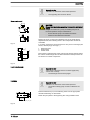
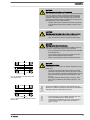
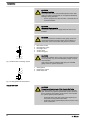
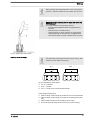
Operating instructions
Diaphragm Motor-Driven Metering Pump
Sigma / 2 Base Type S2Ba
P_SI_0074_SW
Two sets of operating instructions are required for the safe, correct and proper operation of the metering pumps: The
product-specific operating instructions and the "General Operating Instructions for ProMinent® motor-driven metering
pumps and hydraulic accessories".
Both sets of operating instructions are only valid when read together.
Please carefully read these operating instructions before use! · Do not discard!
The operator shall be liable for any damage caused by installation or operating errors!
Technical changes reserved.
Part no. 985908
Original Operating Instructions (2006/42/EC)
BA SI 039 05/11 EN
ProMinent Dosiertechnik GmbH
Im Schuhmachergewann 5-11
69123 Heidelberg
Germany
Telephone: +49 6221 842-0
Fax: +49 6221 842-617
email: [email protected]
Internet: www.prominent.com
4325542425, 1, en_GB
© 2011
2
Supplemental instructions
Supplementary information
Read the following supplementary information in its entirety! Should you
already know this information, you have an even greater need of the Oper‐
ating Instructions.
The following are highlighted separately in the document:
Fig. 1: Please read!
n
Enumerated lists
Instructions
ð Outcome of the handling instructions
- see (reference)
Information
This provides important information relating to the correct
operation of the device or is intended to make your work
easier.
Safety information
Safety information is identified by pictograms - see Safety Chapter.
User information
Two sets of operating instructions are required for the safe, correct and
proper operation of the metering pumps: The product-specific operating
instructions and the "General Operating Instructions for ProMinent® motordriven metering pumps and hydraulic accessories".
Both sets of operating instructions are only valid when read together.
Please read these operating instructions carefully before use! Do not dis‐
card!
State the identity code and serial number
Please state identity code and serial number, which you can find on the
nameplate when you contact us or order spare parts. This enables the
device type and material versions to be clearly identified.
General non-discriminatory approach
In order to make it easier to read, this document uses the male form in
grammatical structures but with an implied neutral sense. It is aimed
equally at both men and women. We kindly ask female readers for their
understanding in this simplification of the text.
3
Table of contents
Table of contents
1
Identity code S2Ba.......................................................................... 5
2
Safety chapter................................................................................. 7
3
Storage, transport and unpacking................................................. 10
4
Overview of equipment and control elements............................... 12
5
Functional description.................................................................... 14
5.1
5.2
5.3
5.4
Drive unit...............................................................................
Liquid end..............................................................................
Integral relief valve................................................................
Multi-layer safety diaphragm.................................................
14
15
15
16
6
Assembly....................................................................................... 18
7
Installation..................................................................................... 20
7.1 Installation, hydraulic............................................................. 20
7.2 Installation, electrical............................................................. 24
8
Start up.......................................................................................... 27
9
Maintenance.................................................................................. 31
10
Repairs.......................................................................................... 34
10.1 Cleaning valves................................................................... 34
10.2 Replacing the metering diaphragm..................................... 36
11
Troubleshooting............................................................................. 38
12
Decommissioning.......................................................................... 40
13
Technical data............................................................................... 43
13.1 Performance data................................................................
13.2 Shipping weight...................................................................
13.3 Wetted materials.................................................................
13.4 Ambient conditions..............................................................
13.4.1 Ambient temperatures......................................................
13.4.2 Media temperatures.........................................................
13.4.3 Air humidity......................................................................
13.5 Motor data...........................................................................
13.6 Stroke actuator....................................................................
13.7 Stroke control drive.............................................................
13.8 Diaphragm rupture sensor..................................................
13.9 Stroke sensor "Sigma"........................................................
13.10 Relay.................................................................................
13.11 Gear oil..............................................................................
13.12 Sound pressure level........................................................
13.13 Supplementary information for modified versions.............
4
43
44
45
45
45
45
46
46
47
47
47
48
48
48
49
49
14
EC Declaration of Conformity........................................................ 50
15
Decontamination declaration......................................................... 52
Identity code S2Ba
1
Identity code S2Ba
S2Ba Sigma 2 basic type
H
Main power end, diaphragm
Type:
Power (at 50 Hz)
bar
l/h***
16050
10*
50
16090
10*
90
16130
10*
130
07120
7
120
07220
7
220
04350
4
350
Dosing head material
PV
PVDF
SS
Stainless steel
Seal material
T
PTFE seal
Displacement
S
Multi-layer safety diaphragm with optical break indicator
A
Multi-layer safety diaphragm with diaphragm rupture signalling (contact)
H
Diaphragm for hygienic pump head
Dosing head version
0
no valve springs
1
with 2 valve springs, Hastelloy C; 0.1 bar
4 **
with relief valve, FPM seal, no valve springs
5 **
with relief valve, FPM seal, with valve springs
6 **
with relief valve, EPDM seal, no valve springs
7 **
with relief valve, EPDM seal, with valve springs
H
Hygienic pump head with tri-clamp connectors (max. 10 bar)
Hydraulic connector
0
Standard threaded connector (in line with technical data)
1
Union nut and PVC insert
2
Union nut and PP insert
3
Union nut and PVDF insert
4
Union nut and SS insert
7
Union nut and PVDF hose nozzle
8
Union nut and SS hose nozzle
9
Union nut and stainless steel welding sleeve
Version
0
With ProMinent® Logo (standard)
1
Without ProMinent® Logo
5
Identity code S2Ba
S2Ba Sigma 2 basic type
M
Modified*
* order-related version, for
pump features see paperwork
for order
Electric power supply
S
3 ph, 230 V/400 V 50/60 Hz
M
1 ph AC, 230 V 50 Hz
N
1 ph AC, 115 V 60 Hz
L
3 ph, 230 V/400 V, 50 Hz, (Exe, Exd)
P
3 ph, 265 V/440 V, 60 Hz, (Exe, Exd)
R
3 ph, variable speed motor, 230/400 V
V(0)
Variable speed motor with integrated Frequency
converter 1 ph, 230 V, 50/60 Hz
Z
Speed control complete 1 ph, 230 V, 50/60 Hz
(control motor + frequency converter)
1
No motor, with B14 flange, size 71 (DIN)
2
No motor, with C 56 flange (NEMA)
3
No motor, with B 5, size 63 (DIN)
Degree of protection
0
IP 55 (standard)
1
Exe version ATEX-T3
2
Exd version ATEX-T4
Stroke sensor
0
No stroke sensor (standard)
2
Pacing relay (reed relay)
3
Stroke sensor (Namur) for haz‐
ardous locations
Stroke length adjustment
0
Manual (standard)
1
With servomotor, 230 V,
50/60 Hz
2
With servomotor, 115 V,
50/60 Hz
3
With control motor 0...20 mA
230 V, 50/60 Hz
4
With control motor 4...20 mA
230 V, 50/60 Hz
5
With control motor 0...20 mA
115 V, 50/60 Hz
6
With control motor 4...20 mA
115 V, 50/60 Hz
FPM = fluorine rubber
* for SST = 16 bar
** Standard with tube nozzle in the bypass Threaded connection on
request.
*** Exact values - see "Technical Data" chapter.
6
Safety chapter
2
Safety chapter
Explanation of the safety information
Warning signs denoting different types of
danger
The following signal words are used in these operating instructions to
identify different severities of a hazard:
Signal word
Meaning
WARNING
Denotes a possibly hazardous sit‐
uation. If this is disregarded, you
are in a life-threatening situation
and this can result in serious inju‐
ries.
CAUTION
Denotes a possibly hazardous sit‐
uation. If this is disregarded, it
could result in slight or minor inju‐
ries or material damage.
The following warning signs are used in these operating instructions to
denote different types of danger:
Warning signs
Type of danger
Warning – high-voltage.
Warning – danger zone.
Correct and proper use
n
n
n
n
n
n
n
n
n
n
n
The pump may only be used to dose liquid metering chemicals.
In potentially explosive atmospheres in zone 1, device category II 2G
of explosion group II C, the pump must only be operated according to
the with the relevant nameplate (and the respective EC Declaration of
Conformity) for pumps for potentially explosive atmospheres com‐
plying with Directive 94/9/EC in accordance with the European guide‐
lines. The explosion group, category and protection class declared on
the marking must correspond with or be better than the given condi‐
tions in the intended field of application.
Only SST design pumps may be used with combustible feed chemi‐
cals.
The pump may only be started up after it has been correctly installed
and commissioned in accordance with the technical data and specifi‐
cations contained in the operating instructions.
The general limitations with regard to viscosity limits, chemical resist‐
ance and density must be observed - see also ProMinent resistance
list (In the product catalogue or at www.prominent.com)!
Any other uses or modifications are prohibited.
Pumps without the relevant nameplate (and the respective EC Decla‐
ration of Conformity) for pumps for potentially explosive atmospheres
must never be operated in potentially explosive atmospheres.
The pump is not intended for the dosing of gaseous media or solids.
The pump is not intended for unprotected outside use.
The pump should only be operated by trained and authorised per‐
sonnel.
You are obliged to observe the information contained in the operating
instructions at the different phases of the device's service life.
7
Safety chapter
Safety information
WARNING!
Warning of hazardous or unknown feed chemical
Should a hazardous or unknown feed chemical be used, it
may escape from the hydraulic components when working
on the pump.
–
–
Take appropriate protective measures before working on
the pump (protective eyewear, protective gloves, ...).
Read the safety data sheet on the feed chemical.
Drain and flush the liquid end before working on the
pump.
CAUTION!
Warning of feed chemical spraying around
Feed chemical can spray out of the hydraulic components if
they are manipulated or opened due to pressure in the liquid
end and adjacent parts of the system.
–
–
Disconnect the pump from the mains power supply and
ensure that it cannot be switched on again by unauthor‐
ised persons.
Depressurise the system before commencing any work
on hydraulic parts.
CAUTION!
Warning of feed chemical spraying around
An unsuitable feed chemical can damage the parts of the
pump contacted by the chemical.
–
Take into account the resistance of the material con‐
tacted by the chemical when selecting the feed chemical
- refer to the ProMinent ® resistance list in the product
equipment catalogue or at www.prominent.com.
CAUTION!
Danger of personal and material damage
The use of untested third party parts can result in damage to
personnel and material damage.
–
Only fit parts to dosing pumps, which have been tested
and recommended by ProMinent.
CAUTION!
Danger from incorrectly operated or inadequately maintained
pumps
Danger can arise from a poorly accessible pump due to
incorrect operation and poor maintenance.
–
–
Ensure that the pump is accessible at all times.
Adhere to the maintenance intervals.
CAUTION!
Warning of illegal operation
Observe the regulations that apply where the unit is to be
installed.
8
Safety chapter
Information in the event of an emergency
In the event of an electrical accident, disconnect the mains cable from the
mains or press the emergency cut-off switch fitted on the side of the
system!
If feed chemical escapes, also depressurise the hydraulic system around
the pump as necessary. Adhere to the safety data sheet for the feed
chemical.
Qualification of personnel
Activity
Qualification level
Storage, transport, unpacking
Instructed personnel
Installation, installation of hydraulic
system
Technical personnel
Installation, electrical
Electrical technician
Operation
Instructed personnel
Maintenance, repair
Technical personnel
Decommissioning, disposal
Technical personnel
Troubleshooting
Technical personnel, electrical
technician, instructed personnel
Explanation of the terms:
Qualified personnel
A qualified employee is deemed to be a person who is able to assess the
tasks assigned to him and recognise possible dangers based on his/her
technical training, knowledge and experience, as well as knowledge of
pertinent regulations.
Note:
A qualification of equal validity to a technical qualification can also gained
by several years employment in the relevant work area.
Electrical technician
Electrical technicians are deemed to be people, who are able to complete
work on electrical systems and recognize and avoid possible dangers
independently based on their technical training and experience, as well as
knowledge of pertinent standards and regulations.
Electrical technicians should be specifically trained for the working envi‐
ronment in which the are employed and know the relevant standards and
regulations.
Electrical technicians must comply with the provisions of the applicable
statutory directives on accident prevention.
Instructed personnel
An instructed person is deemed to be a person who has been instructed
and, if required, trained in the tasks assigned to him/her and possible dan‐
gers that could result from improper behaviour, as well as having been
instructed in the required protective equipment and protective measures.
Customer Service department
Customer Service department refers to service technicians, who have
received proven training and have been authorised by ProMinent or Pro‐
Maqua to work on the system.
Sound pressure level
Sound pressure level LpA < 70 dB in accordance with EN ISO
20361:2010-10
at maximum stroke length, maximum stroke rate, maximum back pressure
(water)
9
Storage, transport and unpacking
3
Storage, transport and unpacking
Safety information
WARNING!
Only return metering pumps for repair in a cleaned state and
with a flushed liquid end - refer to the section on decommis‐
sioning!
Only send metering pumps with a filled in Decontamination
Declaration form. The Decontamination Declaration consti‐
tutes an integral part of an inspection / repair order. A unit
can only be inspected or repaired when a Declaration of
Decontamination Form is submitted that has been completed
correctly and in full by an authorised and qualified person on
behalf of the pump operator.
The "Decontamination Declaration Form" can be found in the
Appendix or at www.prominent.com.
CAUTION!
Danger of material damage
The device can be damaged by incorrect or improper storage
or transportation!
–
–
–
–
Scope of supply
Compare the delivery note with the scope of supply:
n
n
n
n
Storage
The unit should only be stored or transported in a well
packaged state - preferably in its original packaging.
Only transport the unit when the red gear bleeding plug
is pushed in.
The packaged unit should also only be stored or trans‐
ported in accordance with the stipulated storage condi‐
tions.
The packaged unit should be protected from moisture
and the ingress of chemicals.
Metering pump with mains power cable
If necessary, connector kit for hose/pipe connection
Product-specific operating instructions with EC Declaration of Con‐
formity and supplementary information CD for ProMinent pump oper‐
ating instructions.
As necessary, documents for options and accessories
Personnel:
n
Technical personnel
1.
Place the caps on the valves.
2.
Check if the red gear bleeding plug is pushed in.
3.
Preferably place the pump standing vertically on a pallet and secure
against falling over.
4.
Cover the pump with a tarpaulin cover - allowing rear ventilation.
Store the pump in a dry, closed shop under the following ambient condi‐
tions.
10
Storage, transport and unpacking
Ambient conditions
Data
Value Unit
Minimum storage and transport tempera‐
ture
-10 °C
Maximum storage and transport tempera‐
ture
+50 °C
Maximum air humidity *
95 % rel.
humidity
* non-condensing
11
Overview of equipment and control elements
4
Overview of equipment and control elements
1
2
4
3
5
P_SI_0068_SW
Fig. 2: Overview of equipment and control elements S2Ba
1
2
3
4
5
Drive motor
Drive unit
Stroke length adjustment knob
Liquid end with relief valve
Diaphragm rupture sensor
1
2
P_SI_0088_SW
Fig. 3: Sigma control elements
1
2
12
Relief valve
Diaphragm rupture sensor (visual)
Overview of equipment and control elements
75%
0
50
25
75
20
30%
0
0
25
5
5
0
10
P_SI_0095_SW
Fig. 4: Adjusting the stroke length
n
n
n
100 % = 4 rotations
25 % = 1 rotation
0.5 % = 1 scale mark on stroke adjustment dial
PG9
PG11
1
2
3
P_SI_0036
A
B
Fig. 5: Front cover for version with pacing relay
A
B
Pacing relay cable
Supply voltage cable for pacing relay PCB
13
Functional description
5
Functional description
5.1 Drive unit
The metering pump is an diaphragm pump, the stroke length of which can
be adjusted. An electric motor (1) drives the pump. A worm gear (2) steps
down its drive rotation A cam (3), in conjunction with the uptake fork (8)
converts this into an oscillation movement of the slide rod (4). A return
spring (5) presses the uptake fork together with the slide rod positively
against the cam thus producing the reciprocal stroke. The stroke length
can be adjusted by the stroke adjustment dial (6) and the shaft (7). The
different stroke lengths are in effect caused by a limitation of the reciprocal
strokes (see Ä “Illustration of the stroke movement ” on page 14). The
slide rod transmits the stoke motion to the metering diaphragms.
1 2 5 4
10
3
8
7
6
P_SI_0077_SW
Fig. 6: Section through the drive unit Sigma 2
1
2
3
4
5
6
7
8
Illustration of the stroke movement
Electric motor
Worm gear
Eccentric cam
Slide rod
Return spring
Stroke adjustment dial
Shaft
Uptake fork
a)
b)
s
s
ω
0
180
360
ω
0
180
360
P_PL_0009_SW
Fig. 7: Stroke movement at a) maximum stroke length and b) reduced
stroke length.
s
⍵
+
-
14
Stroke velocity
Angle of rotation of eccentric cam
Pressure stroke
Suction stroke
Functional description
5.2 Liquid end
The diaphragm (2) hermetically shuts off the pump volume of the dosing
head (4) towards the outside. The suction valve (1) closes as soon as the
diaphragm (2) is moved in to the dosing head (4) and the feed chemical
flows through the discharge valve (3) out of the dosing head. The dis‐
charge valve (3) closes as soon as the diaphragm (2) is moved in the
opposite direction due to the vacuum pressure in the dosing head and
fresh feed chemical flows through the suction valve (1) into the dosing
head. One cycle is thus completed.
3
4
5
13
2
1
Fig. 8: Cross-section through the liquid end
1
2
3
4
5
13
Suction valve
Diaphragm
Discharge valve
Dosing head
Backplate
Safety diaphragm
5.3 Integral relief valve
The integral relief valve normally operates as a simple, directly controlled
bleeder valve. As soon as the pressure exceeds the pressure value, which
is set using the large spring (1), it lifts the ball (2). The feed chemical then
flows out through the hose connection (5), e.g. into a storage tank.
The integral relief valve can only protect the motor and the gear, and then
only against impermissible positive pressure that is caused by the
metering pump itself. It cannot protect the system against positive pres‐
sure.
The integral relief valve works as a bleed valve if the rotary dial (3) is
turned clockwise up to the "open" stop: This relieves the high force caused
by the large spring (1) which was acting on the ball (2) - the ball is now
controlled by the low force of the small spring (4). The integral relief valve
is, when used in this way, a priming aid for starting up the pump against
pressure.
15
Functional description
1
2
3
4
5
P_SI_0019
Fig. 9: Integral relief valve
1
2
3
4
5
Spring, large
Ball
Rotary dial
Spring, small
Hose connection
5.4 Multi-layer safety diaphragm
The multi-layer safety diaphragm has the same function as the conven‐
tional double diaphragm system with working and safety diaphragms; how‐
ever it also has the advantage that both diaphragms are joined together in
a single unit.
If the working layer (1) breaks, the feed chemical penetrates between the
working and safety (2) layers and spreads out. The safety layer ensures
that not feed chemical penetrates to the outside.
As soon as the feed chemical reaches the flap (3) on the edge of the multilayer safety diaphragm, it inflates it. The flap presses a piston (4) in the
membrane rupture sensor (5), so that this triggers.
With the visual diaphragm rupture sensor, the lowered red cylinder (6)
springs forward beneath the transparent cover (7) so that it then becomes
clearly visible - see Fig. 10.
With the electrical diaphragm rupture sensor, a switch is switched. A sig‐
nalling device must be connected to signal the diaphragm rupture.
Fig. 10: Visual diaphragm rupture sensor, triggered and untriggered
16
Functional description
1
7
6
5
4
2
3
P_SI_0020_SW
Fig. 11: Section through the visual membrane rupture sensor Sigma
("Visual break indicator" version)
1
2
3
4
5
6
7
Working layer (≙ operating diaphragm)
Safety layer (≙ safety diaphragm)
Flap
Piston
Diaphragm rupture sensor
Cylinder, red
Cover, transparent
17
Assembly
6
Assembly
WARNING!
Warning about personal and material damage
EX pumps only: When operating in EX areas, certain sub‐
jects must be observed.
–
The chapter "Important supplements for metering pumps
in EX zones" of the "General Operating Instructions on
ProMinent ® Motor-Driven Metering Pumps and Hydraulic
Accessories" must be observed in all cases.
CAUTION!
Danger of material damage
The device can be damaged by incorrect or improper storage
or transportation!
–
–
–
–
The unit should only be stored or transported in a well
packaged state - preferably in its original packaging.
Only transport the unit when the red gear bleeding plug
is pushed in.
The packaged unit should also only be stored or trans‐
ported in accordance with the stipulated storage condi‐
tions.
The packaged unit should be protected from moisture
and the ingress of chemicals.
CAUTION!
Warning about personal and material damage
Personal and material damage may be caused if the unit is
operated outside of the permissible ambient conditions.
–
Please observe the permissible ambient conditions refer to the chapter entitled "Technical Data".
Supporting floor
WARNING!
Risk of electric shock
If water or other electrically conducting liquids penetrate into
the drive housing, an electric shock may occur.
–
h
Position the pump so that drive housing cannot be
flooded.
P_MOZ_0016_SW
Fig. 12
18
WARNING!
The pump can break through the supporting floor or slide off
it
– The supporting floor must be horizontal, smooth and per‐
manently load-bearing.
Assembly
Capacity too low
Vibrations can disturb the valves of the liquid end.
–
The supporting floor must not vibrate.
Space requirement
CAUTION!
Danger from incorrectly operated or inadequately maintained
pumps
Danger can arise from a poorly accessible pump due to
incorrect operation and poor maintenance.
A
–
–
A
Ensure that the pump is accessible at all times.
Adhere to the maintenance intervals.
Position the pump so that control elements such as the stroke length
adjustment knob, the indicating dial A or the oil inspection window are
accessible.
P_MOZ_0018_SW
Fig. 13
In so doing, ensure there is enough space to carry out an oil change (vent
screws, oil drain plugs, oil trough ...).
1
2
3
1
f
2
Ensure there is sufficient free space (f) around the dosing head as well as
the suction and discharge valve so that maintenance and repair work can
be carried out on these components.
f
f
Discharge valve
Dosing head
Suction valve
3
P_MOZ_0017_SW
Fig. 14
Liquid end alignment
Capacity too low
If the valves of the liquid end do not stand upright, they
cannot close correctly.
–
The discharge valve must be upright.
Fastening
Capacity too low
Vibrations can disturb the valves of the liquid end.
–
m
DN
Secure the metering pump so that no vibrations can
occur.
Take the dimensions (m) for the fastening holes from the appropriate
dimensional drawings or data sheets.
Fasten the pump base to the supporting floor using suitable screws.
m
P_MOZ_0015_SW
Fig. 15
19
Installation
7
Installation
CAUTION!
Danger of personnel injury and material damage
The disregard of technical data during installation may lead
to personal injuries or damage to property.
–
Observe the technical data- refer to chapter "Technical
Data" and, where applicable, the operating instructions
of the accessories.
7.1 Installation, hydraulic
WARNING!
Warning about personal and material damage
EX pumps only: When operating in EX areas, certain sub‐
jects must be observed.
–
The chapter "Important supplements for metering pumps
in EX zones" of the "General Operating Instructions on
ProMinent ® Motor-Driven Metering Pumps and Hydraulic
Accessories" must be observed in all cases.
WARNING!
Warning of feed chemical reactions to water
Feed chemicals that should not come into contact with water
may react to residual water in the liquid end that may origi‐
nate from works testing.
–
–
Blow the liquid end dry with compressed air through the
suction connector.
Then flush the liquid end with a suitable medium through
the suction connector.
WARNING!
The following measures are an advantage when working with
highly aggressive or hazardous feed chemicals:
–
–
Install a bleed valve with recirculation in the storage
tank.
Install an additional shut-off valve on the discharge or
suction ends.
CAUTION!
Suction problems possible
For feed chemicals with a particle size greater than 0.3 mm,
the valves may no longer close properly.
–
20
Install a suitable filter in the suction line.
Installation
CAUTION!
Warning against the discharge line bursting
With a closed discharge line (e.g. due to a clogged discharge
line or by closing a valve), the pressure that the metering
pump generates can reach several times the permissible
pressure of the system or the metering pump. This could
lead to lines bursting resulting in dangerous consequences
with aggressive or toxic feed chemicals.
–
Install a relief valve that limits the pressure of the pump
to the maximum permissible operating pressure of the
system.
CAUTION!
Warning against bursting of the suction or discharge lines
Hose lines with insufficient pressure rating may burst.
–
Only use hose lines with the required pressure rating.
CAUTION!
Warning against lines disconnecting
With suction, discharge and relief lines installed incorrectly
can loosen / disconnect from the pump connection.
–
–
–
Only use original hoses with the specified hose diameter
and wall thickness.
Only use clamping rings and hose nozzles that corre‐
spond with the respective hose diameter.
Always connect the lines without mechanical tension.
CAUTION!
Warning against leaks
Leaks can occur on the pump connection depending on the
insert used.
–
P_SI_0021
Fig. 16: Moulded composite seals with
corrugated insert
–
The pump is supplied with PTFE moulded composite
seals with a flare, which are used for the pump connec‐
tions. They seal the connections between grooved pump
valves and the grooved inserts from ProMinent - see
Fig. 16.
In the event that an unflared insert is used (e.g. third
party part), an elastomer flat seal must be used - see
Fig. 17.
Numerous installation instructions with drawings are con‐
tained in the "General Operating Instructions for ProMinent®
metering pumps and hydraulic accessories".
P_SI_0022
Fig. 17: Elastomer flat seal with an insert
without flare
–
–
Precise metering is only possible when the back pres‐
sure is maintained above 1 bar at all times.
If metering at atmospheric pressure, a back pressure
valve should be used to create a back pressure of
approx. 1.5 bar.
21
Installation
CAUTION!
Warning of backflow
A back pressure valve, spring-loaded injection valve, relief
valve, foot valve or a liquid end do not represent absolutely
leak-tight closing elements.
–
For this purpose use a shut-off valve, a solenoid valve or
a vacuum breaker.
CAUTION!
Warning of illegal operation
Observe the regulations that apply where the unit is to be
installed.
CAUTION!
To check the pressure conditions in the piping system it is
recommended that connecting options are provided for a
manometer close to the suction and pressure connector.
1
2
3
1
2
3
4
5
Manometer socket
Discharge line (pipe)
Discharge valve
Suction valve
Suction line (pipe)
4
1
CAUTION!
Connect the pipelines to the pump so that no residual forces
act on the pump, e.g. due to the offsetting, weight or expan‐
sion of the line.
5
P_MOZ_0020_SW
Fig. 18: Manometer connecting options
1
2
Only connect steel or stainless steel piping via a flexible
piping section to a plastic liquid end.
1
2
3
Steel pipeline
Flexible pipe section
Plastic liquid end
3
P_MOZ_0021_SW
Fig. 19: Steel pipeline at the liquid end
Integral relief valve
CAUTION!
Danger due to incorrect use of the integral relief valve
The integral relief valve can only protect the motor and the
gear, and then only against impermissible positive pressure
that is caused by the metering pump itself. It cannot protect
the system against positive pressure.
–
–
22
Protect the motor and gear of the system against posi‐
tive pressure using other mechanisms.
Protect the system against illegal positive pressure using
other mechanisms.
Installation
CAUTION!
Warning of feed chemical spraying around
If no relief valve was connected to the overflow line, the feed
chemical sprays out of the hose connection as soon as the
relief valve opens.
–
An overflow line must always be connected to the inte‐
gral relief valve and be fed back to the storage tank or if required by the regulations - into a special storage
tank.
CAUTION!
Danger of cracking
Cracking of the PVT liquid end can occur if a metal overflow
line is connected to the relief valve.
–
Never connect a metal overflow line to the relief valve.
CAUTION!
Danger of the integral relief valve failing
The integral relief valve no longer operates reliably with feed
chemicals having a viscosity of greater than 200 mPa s.
–
Only use the integral relief valve with feed chemicals
having a viscosity up to 200 mPa s.
CAUTION!
Warning against leaks
Feed chemical which remains in the overflow line at the relief
valve, can attack the valve or cause it to leak
–
Route the overflow line with a continuous slope and
moreover with the tube nozzle pointed downwards - see
Fig. 20.
If the overflow line is fed into the suction line, the bleed func‐
tion is blocked.
P_SI_0023
Fig. 20: Permissible alignment of the relief
valve
Therefore lead the overflow line back into the storage tank.
When operating the integral relief valve close to the opening
pressure, a minimal overflow into the overflow line can occur.
Diaphragm rupture sensor
CAUTION!
Danger resulting from unnoticed diaphragm rupture
If the pump has been ordered with an electric diaphragm rup‐
ture sensor, it still has to be installed.
–
Screw the enclosed diaphragm rupture sensor into the
liquid end (no seal necessary).
23
Installation
CAUTION!
Warning of unnoticed diaphragm rupture
Only above approximately 2 bar system back pressure is a
signal generated upon a diaphragm rupture.
–
Only rely on the diaphragm rupture sensor at back pres‐
sures greater than 2 bar.
7.2 Installation, electrical
WARNING!
Danger of electric shock
Unprofessional installation may lead to electric shocks.
–
–
All cable cores cut to length must be provided with cable
end sleeves.
The Installation, electrical of the device may only be
undertaken by technically trained personnel.
WARNING!
Warning about personal and material damage
EX pumps only: When operating in EX areas, certain sub‐
jects must be observed.
–
The chapter "Important supplements for metering pumps
in EX zones" of the "General Operating Instructions on
ProMinent ® Motor-Driven Metering Pumps and Hydraulic
Accessories" must be observed in all cases.
CAUTION!
Warning about personal and material damage
Also observe the "General Operating Instructions for ProMi‐
nent ® Motor-Driven Metering Pumps and Hydraulic Accesso‐
ries"!
Personnel:
n
Electrician
What requires electrical installation?
n
n
n
n
n
n
n
n
24
Motor
External fan (option)
Stroke control drive (Option)
Stroke adjusting drive (Option)
Diaphragm rupture sensor (Option)
Stroke sensor (Option)
Pacing relay (option)
Frequency converter (option)
Installation
Motor
CAUTION!
Pump can be damaged
The pump can be damaged if the motor drives the pump in
the wrong direction.
–
When connecting the motor, pay attention to the correct
direction of rotation indicated by the arrow on the fan
cover, as shown in Fig. 21.
P_SI_0012_SW
Fig. 21: Direction of rotation of motor
1.
Install a motor protection switch, as the motors have no fuse.
2.
Install an emergency cut-off switch or include the motor in the emer‐
gency cut-off management of the system.
3.
Use a suitable cable between the motor terminal box and power
supply.
–
–
–
–
Key motor data can be found on the unit nameplate.
Motor data sheets can be requested for more informa‐
tion.
The terminal wiring diagram is located in the terminal
box.
Notes on the speed controlled motor with external fan
and temperature monitoring can be found in the "Gen‐
eral operating instructions for ProMinent® motor-driven
metering pumps and hydraulic accessories"!
Diaphragm rupture sensor (Option)
WARNING!
Risk of electric shock
In event of a defect, there is a risk of electric shock when
conductive feed chemical are used.
–
For safety reasons we recommend connecting to a pro‐
tective low voltage, e.g. in accordance with EN 60335-1
(SELV ).
CAUTION!
Danger resulting from unnoticed diaphragm rupture
If the pump has been ordered with an electric diaphragm rup‐
ture sensor, it must also be electrically installed.
–
Install the enclosed diaphragm rupture sensor electri‐
cally to a suitable monitoring device.
a) Diaphragm rupture sensor with switch contact
–
The cable can be poled as required.
b) Namur sensor, inherently safe
The monitor / power supply installed by the customer must be able to eval‐
uate the current variations of the Namur sensor for indicating a diaphragm
rupture!
25
Installation
Stroke sensor (identity code specification
"Stroke sensor": 3)
Connect the stroke sensor to a suitable monitoring device according
to the technical data provided with the monitoring device and that of
the stroke sensor - see chapter "Technical data".
Pacing relay (identity code specification
"Stroke sensor": 2)
1.
Install the cable which originates from the pacing relay - see the
figure in the chapter entitled "Overview of equipment and control
elements": Cable A, left.
The cable polarity is unimportant.
2.
Install the power supply cable to the pacing relay PCB - see the
figure in the chapter entitled "Overview of equipment and control
elements": Cable B, right.
CAUTION!
Warning of overload
If the current through the relay becomes too high, it
can be destroyed by heating.
–
Fit a circuit breaker.
Pacing relay terminal output data
Data
Value Unit
Maximum voltage
24 VDC
Maximum current
100 mA
Closing duration, approx.
100 ms
50 x 106 (10 V, Play
10 mA)
Service life *
* at rated load
The contacts are potential-free.
The pacing relay is a N/O as standard.
Supply voltage for pacing relay PCB
Available supply vol‐
tages
Mains supply fre‐
quency
Power consumption
230 V AC (180-254 V)
50 / 60 Hz
10 mA (at 230 V, 50 Hz)
115 V AC (90-134 V)
50 / 60 Hz
15 mA (at 115 V, 60 Hz)
24 V DC (20-28 V)
-
10 mA (at 24 V DC)
Other units
Install the other units according to their documentation.
26
Start up
8
Start up
Safety information
WARNING!
Warning about personal and material damage
EX pumps only: When operating in EX areas, certain sub‐
jects must be observed.
–
The chapter "Important supplements for metering pumps
in EX zones" of the "General Operating Instructions on
ProMinent ® Motor-Driven Metering Pumps and Hydraulic
Accessories" must be observed in all cases.
WARNING!
Fire danger
Only with combustible media: These may start to burn when
combined with oxygen.
–
When filling and draining the liquid end, the feed chem‐
ical must not come into contact with oxygen.
CAUTION!
Warning about personal and material damage
Also observe the "General Operating Instructions for ProMi‐
nent ® Motor-Driven Metering Pumps and Hydraulic Accesso‐
ries"!
CAUTION!
Warning of personal injury and material damage
The metering pump may only be operated by trained per‐
sonnel. The operator is responsible for ensuring that under
the given operating conditions (pressure, temperature, corro‐
siveness, etc.) danger to the operating personnel is avoided
by use of appropriate accident prevention measures.
CAUTION!
Feed chemical could escape
– Check suction and discharge lines, liquid end and valves
for leak-tightness and tighten if necessary.
– Check whether the necessary flushing pipes are con‐
nected.
CAUTION!
Prior to commissioning check the drive motor and corre‐
sponding ancillary equipment is connected according to reg‐
ulations.
CAUTION!
When using pumps with speed control, observe the instruc‐
tions in the frequency converter operating instructions.
27
Start up
CAUTION!
Possible environmental and material damage
In event the red gear bleeding plug is sealed, during opera‐
tion it prevents any pressure compensation between the
drive housing and the surroundings. This ensure that oil can
be pushed from the drive housing.
–
Remove the gear bleeding plug before commissioning.
Remove the gearbox vent stopper
Before start up pull the red gearbox vent stopper off, see chapter "Over‐
view of equipment and control elements".
Checking the oil level
When the pump is idle, check whether the oil level in the pump is in the
middle of the oil level indicator.
This will rule out the pump losing oil and suffering damage.
Checking the direction of rotation
When commissioning the unit, check whether the drive motor is rotating
correctly - check this against the arrow on the motor housing or the dia‐
gram in the chapter entitled "Electrical Installation."
Using the integral relief valve
CAUTION!
Danger due to incorrect use of the integral relief valve
The integral relief valve can only protect the motor and the
gear, and then only against impermissible positive pressure
that is caused by the metering pump itself. It cannot protect
the system against positive pressure.
–
–
Protect the motor and gear of the system against posi‐
tive pressure using other mechanisms.
Protect the system against illegal positive pressure using
other mechanisms.
CAUTION!
Danger of the integral relief valve failing
The integral relief valve no longer operates reliably with feed
chemicals having a viscosity of greater than 200 mPa s.
–
Priming against pressure
Only use the integral relief valve with feed chemicals
having a viscosity up to 200 mPa s.
1.
Hydraulically isolate the discharge line from the pump using an iso‐
lation device.
2.
Turn the rotary dial on the integral relief valve in a clockwise direc‐
tion up to the "close" stop.
ð The excess pressure escapes through the hose connector.
3.
Run the pump until the feed chemical coming out of the hose con‐
nector is free from bubbles.
4.
Turn the rotary dial on the integral relief valve in a clockwise direc‐
tion up to the "close" stop.
ð The pump can be started.
28
Start up
When operating the integral relief valve close to the opening
pressure, a minimal overflow into the overflow line can occur.
Eliminating suction problems (only for single ball valves with
PTFE ball seat)
For suction problems occurring during start up:
–
–
–
–
Exclude the possibility that there are foreign bodies in
the valve.
Place the valve on a stable surface.
Using a hammer (1) and a brass bar (2), gently tap the
PTFE ball seat above the valve ball - see figure below.
Then with the valve in a damp condition allow it to prime.
Fig. 22: Tapping the valve set disc
Adjusting the stroke length
Only adjust the stroke length when the pump is running. This
is easier and also better for the pump.
75%
0
50
25
75
20
30%
0
0
25
5
0
5
10
P_SI_0095_SW
Fig. 23: Adjusting the stroke length
n
n
n
100 % = 4 rotations
25 % = 1 rotation
0.5 % = 1 scale mark on stroke adjustment dial
Correctly adjusting the pump:
n
n
n
n
Select as large a stroke length as possible for viscous feed chemicals.
Select as large a stroke length as possible for outgassing feed chemi‐
cals.
Select as high a stroke rate as possible for good mixing.
Do not set the stroke length at less than 30 % for precise dosing.
29
Start up
Diaphragm rupture sensor
CAUTION!
Danger resulting from unnoticed diaphragm rupture
If the pump has been ordered with an electric diaphragm rup‐
ture sensor, it still has to be installed.
–
Screw the enclosed diaphragm rupture sensor into the
liquid end (no seal necessary).
CAUTION!
Warning of unnoticed diaphragm rupture
Only above approximately 2 bar system back pressure is a
signal generated upon a diaphragm rupture.
–
30
Only rely on the diaphragm rupture sensor at back pres‐
sures greater than 2 bar.
Maintenance
9
Maintenance
Safety information
WARNING!
Warning about personal and material damage
EX pumps only: When operating in EX areas, certain sub‐
jects must be observed.
–
The chapter "Important supplements for metering pumps
in EX zones" of the "General Operating Instructions on
ProMinent ® Motor-Driven Metering Pumps and Hydraulic
Accessories" must be observed in all cases.
WARNING!
It is mandatory that you read the safety information and
specifications in the "Storage, Transport and Unpacking"
chapter prior to shipping the pump.
CAUTION!
Warning of feed chemical spraying around
Feed chemical can spray out of the hydraulic components if
they are manipulated or opened due to pressure in the liquid
end and adjacent parts of the system.
–
–
Disconnect the pump from the mains power supply and
ensure that it cannot be switched on again by unauthor‐
ised persons.
Depressurise the system before commencing any work
on hydraulic parts.
WARNING!
Warning of hazardous or unknown feed chemical
Should a hazardous or unknown feed chemical be used, it
may escape from the hydraulic components when working
on the pump.
–
–
Take appropriate protective measures before working on
the pump (protective eyewear, protective gloves, ...).
Read the safety data sheet on the feed chemical.
Drain and flush the liquid end before working on the
pump.
WARNING!
Danger of an electric shock
When working on the motor or electrical auxiliary equipment,
there is a danger of an electric shock.
–
–
Before working on the motor, take note of the safety
instructions in its operating instructions!
Should external fans, servomotors or other auxiliary
equipment be installed, these should also be discon‐
nected and checked that they are voltage free.
Place a spare parts kit in stock ready for maintenance work.
You can find order numbers in the enclosed "Supplementary
information CD for ProMinent pump operating instructions"
under "Ordering information" - "Spare parts kits".
31
Maintenance
Third party spare parts for the pumps may lead to problems
when pumping.
–
–
Use only original spare parts.
Use the correct spare part kits. In case of doubt, refer to
the exploded views and ordering information contained
in the "Supplementary information CD for ProMinent®
pump operating instructions".
Standard liquid ends:
Interval
Maintenance work
Personnel
After approx. 5,000 oper‐
ating hours
Change gear oil - refer to "Changing gear oil" in this chapter.
Instructed personnel
Quarterly
Check the oil level.
Quarterly*
n
n
n
n
n
n
Check that the metering lines are fixed firmly to the liquid end.
Check that the suction valve and discharge valve are correctly
seated.
Check that the dosing head screws are tight
Check the condition of the metering diaphragm - see Ä “Check
the condition of the metering diaphragm” on page 32.
Check that the flow is correct: Allow the pump to prime briefly.
Check that the electrical connections are intact
Technical personnel
* Under normal loading (approx. 30 % of continuous operation).
Under heavy loading (e.g. continuous operation): shorter intervals.
Check the condition of the metering dia‐
phragm
The metering diaphragm is a wear part, the service life of which is
dependent upon the following parameters:
n
n
n
System back pressure
Operating temperature
Feed chemical properties
When using abrasive feed chemicals, the diaphragm service life is
reduced. In such cases, more frequent checking of the diaphragm is rec‐
ommended.
Tightening torques
Data
Value Unit
Tightening torques for dosing head
screws:
4.5 ... 5.0 Nm
Liquid ends with integral relief valve
WARNING!
Warning of eye injuries
When opening the relief valve, a spring under high tension
can jump out.
–
Changing gear oil
32
Wear protective glasses.
Draining gear oil
1.
Remove the vent screw (1).
2.
Place an oil tray under the oil drain plug (2).
Maintenance
3.
Unscrew the oil drain plug (2) out of the drive housing.
4.
Allow the gear oil to run out of the drive.
5.
Screw in the oil drain plug (2) with a new seal.
Filling with gear oil
Prerequisites: Gear oil according to the "Ordering information" chapter is
available.
1.
Start up the pump.
2.
Slowly pour gear oil through the vent screw (1) opening until the oil
inspection window (3) is half covered.
3.
Allow the pump to run for a further 1... 2 minutes
4.
Replace the vent screw (1).
33
Repairs
10
Repairs
Safety information
WARNING!
Warning about personal and material damage
EX pumps only: When operating in EX areas, certain sub‐
jects must be observed.
–
The chapter "Important supplements for metering pumps
in EX zones" of the "General Operating Instructions on
ProMinent ® Motor-Driven Metering Pumps and Hydraulic
Accessories" must be observed in all cases.
WARNING!
It is mandatory that you read the safety information and
specifications in the "Storage, Transport and Unpacking"
chapter prior to shipping the pump.
CAUTION!
Warning of feed chemical spraying around
Feed chemical can spray out of the hydraulic components if
they are manipulated or opened due to pressure in the liquid
end and adjacent parts of the system.
–
–
Disconnect the pump from the mains power supply and
ensure that it cannot be switched on again by unauthor‐
ised persons.
Depressurise the system before commencing any work
on hydraulic parts.
WARNING!
Warning of hazardous or unknown feed chemical
Should a hazardous or unknown feed chemical be used, it
may escape from the hydraulic components when working
on the pump.
–
–
10.1
Take appropriate protective measures before working on
the pump (protective eyewear, protective gloves, ...).
Read the safety data sheet on the feed chemical.
Drain and flush the liquid end before working on the
pump.
Cleaning valves
Unsuitable spare parts for the valves may lead to problems
for the pumps.
–
–
34
Only use new components that are especially adapted to
fit your valve (both in terms of shape and chemical
resistance).
Use the correct spare part kits. In case of doubt, refer to
the exploded views and ordering information contained
in the "Supplementary information CD for ProMinent®
pump operating instructions".
Repairs
Personnel:
n
Technical personnel
Repairing ball valves
CAUTION!
Warning of personal injury and material damage
Feed chemical may escape from the liquid end, for example,
if ball valves not repaired correctly.
–
–
Only use new components which fit your valve - both in
terms of shape and chemical resistance!
Pay attention to the flow direction of the discharge and
suction connectors when fitting the valve.
1.
Unscrew the valve from the liquid end.
2.
Screw the valve cap (5) on its suction side - see diagram.
3.
Carefully remove the parts from the valve body (2).
4.
Replace the worn parts.
5.
Clean the remaining parts.
6.
Check all parts.
7.
Insert the valve ball (3 and the valve seat (4).
8.
Screw on the valve cap (5).
1
2
3
4
5
P_SI_0013_SW
Fig. 24: Simple cross-section through ball valve
1
2
3
4
5
Flat seal
Valve body
Valve ball
Valve seat
Valve cap
35
Repairs
10.2
Replacing the metering diaphragm
Third party spare parts for the pumps may lead to problems
when pumping.
–
–
Use only original spare parts.
Use the correct spare part kits. In case of doubt, refer to
the exploded views and ordering information contained
in the "Supplementary information CD for ProMinent®
pump operating instructions".
Personnel:
n
Technical personnel
Requirements:
n
n
n
If necessary take protective measures.
Observe the safety data sheet for the feed chemical.
Depressurise the system.
1.
Empty the liquid end: Place the liquid end on its head and allow the
feed chemical to run out; flush out with a suitable medium; flush the
liquid end thoroughly when using hazardous feed chemicals!
2.
With the pump running, move the stroke adjustment dial to the stop
at 0 % stroke length.
ð The drive axle is now difficult to turn.
3.
Switch off the pump.
4.
Unscrew the hydraulic connectors on the discharge and suction
side.
5.
Unscrew the diaphragm rupture sensor from the dosing head.
6.
Remove the 6 screws on the dosing head.
7.
Remove the dosing head.
8.
Loosen the diaphragm from the drive axle with a gentle backwards
turn in the anti-clockwise direction.
9.
Completely unscrew the diaphragm from the drive axle.
10.
Tentatively screw the new diaphragm anticlockwise up to the stop
on the drive axle.
ð The diaphragm now is now seated against the stop of the
thread while the diaphragm flap is within the tolerance range.
1
2
3
A
P_SI_0029
Fig. 25: Tolerance range of the flap on the backplate
1
2
3
A
11.
36
Diaphragm
Backplate
Flap
Tolerance range
Should this not work, remove dirt or swarf out of the thread and
screw the diaphragm correctly onto the drive axle this time.
Repairs
ð If this is still unsuccessful, contact ProMinent-ProMaqua cus‐
tomer service.
12.
Place the dosing head with the screws onto the diaphragm - the
suction connector must be pointing downwards in the pump's fitting
position.
13.
Tighten the screws gently to start with.
14.
Screw the diaphragm rupture sensor into the dosing head.
15.
Start up the pump and adjust the stroke length to 100 %.
16.
Stop the pump and tighten the screws crosswise. Tightening torque
- see Ä “Tightening torques” on page 32.
17.
Start the pump and at maximum pressure, check for leaks.
CAUTION!
Warning of escaping feed chemical
The liquid end may leak should it not be possible to check
the tightening torque of the screws.
–
–
Check the tightening torque of the screws after 24-hours
of operation!
With PP, PC and TT dosing heads also re-check the
tightening torques quarterly!
5
3
13
4
2
1
P_SI_0038
Fig. 26: Cross-section through the liquid end
1
2
3
4
5
13
Suction valve
Metering diaphragm
Discharge valve
Dosing head
Backplate
Safety diaphragm
37
Troubleshooting
11
Troubleshooting
Safety information
WARNING!
Warning about personal and material damage
EX pumps only: When operating in EX areas, certain sub‐
jects must be observed.
–
The chapter "Important supplements for metering pumps
in EX zones" of the "General Operating Instructions on
ProMinent ® Motor-Driven Metering Pumps and Hydraulic
Accessories" must be observed in all cases.
WARNING!
Danger of an electric shock
Personnel working on electrical parts can be electrocuted if
all electrical lines carrying current have not been discon‐
nected.
–
–
–
Disconnect the supply cable before working on the motor
and prevent it from being reconnected accidentally.
Any separately driven fans, servo motors, speed control‐
lers or diaphragm rupture sensors fitted should also be
disconnected.
Check that the supply cables are de-energised.
WARNING!
Warning of hazardous or unknown feed chemical
Should a hazardous or unknown feed chemical be used, it
may escape from the hydraulic components when working
on the pump.
–
–
Take appropriate protective measures before working on
the pump (protective eyewear, protective gloves, ...).
Read the safety data sheet on the feed chemical.
Drain and flush the liquid end before working on the
pump.
CAUTION!
Warning of feed chemical spraying around
Feed chemical can spray out of the hydraulic components if
they are manipulated or opened due to pressure in the liquid
end and adjacent parts of the system.
–
–
Disconnect the pump from the mains power supply and
ensure that it cannot be switched on again by unauthor‐
ised persons.
Depressurise the system before commencing any work
on hydraulic parts.
Tasks
Fault description
Cause
Pump does not prime in spite of The valves are dirty or
full stroke motion and bleeding worn.
Pump does not reach high
pressure rates.
38
Remedy
Personnel
Repair the valves - see chapter enti‐
tled "Repair".
Technical per‐
sonnel
The feed chemical has par‐ Install a suitable filter in the suction
ticles larger than 3 mm.
line.
Technical per‐
sonnel
The valves are dirty or
worn.
Technical per‐
sonnel
Repair the valves - see chapter enti‐
tled "Repair".
Troubleshooting
Fault description
Cause
Remedy
Personnel
The motor is wired incor‐
rectly.
1. Check the mains voltage and
mains frequency.
Electrician
2. Wire the motor correctly.
The mains voltage has
failed.
Eliminate the cause.
Electrician
The dosing head screws
are no longer tight enough.
Tighten the screws crosswise to the
specified tightening torque.
Technical per‐
sonnel
The diaphragm leaks.
Replace the diaphragm - refer to the
"Repair" chapter.
Technical per‐
sonnel
Large leaks occur at the relief
valve.
The ball or ball seat are
dirty or worn.
Clean or replace the ball and ball
seat.
Technical per‐
sonnel
The diaphragm rupture sensor
has triggered.
The operating diaphragm
has ruptured.**
Replace the diaphragm - refer to the
"Repair" chapter.
Technical per‐
sonnel
The drive motor is very hot.
The discharge line is seri‐
ously constricted.
Rectify any constriction of the dis‐
charge line.
Technical per‐
sonnel
All other faults.
Other causes.
Call ProMinent ProMaqua customer
services.
Fluid is escaping from the end
disc
* If necessary use the cross-section drawing of the integral relief valve in
the "Functional Description" chapter.
WARNING!
Warning of eye injuries
When opening the relief valve, a spring under high tension
can jump out.
–
Wear protective glasses.
**
WARNING!
Warning of escaping feed chemical
When dosing combustible feed chemicals or in hazardous
locations, under no circumstances must the second dia‐
phragm also rupture.
–
If the pump membrane rupture sensor triggers, stop the
pump immediately and only restart once a new multilayer safety diaphragm is fitted.
CAUTION!
Warning of inaccurate dosing
Once the operating membrane has ruptured, precise dosing
of the pump can no longer be guaranteed.
–
–
Do not continue to use the pump for critical process
dosing.
For uncritical processes, the pump can continue to be
operated for some time after the break in emergency
service mode at full operating pressure and free from
leaks up until replacement of the diaphragm.
39
Decommissioning
12
Decommissioning
Decommissioning
WARNING!
Warning about personal and material damage
EX pumps only: When operating in EX areas, certain sub‐
jects must be observed.
–
The chapter "Important supplements for metering pumps
in EX zones" of the "General Operating Instructions on
ProMinent ® Motor-Driven Metering Pumps and Hydraulic
Accessories" must be observed in all cases.
WARNING!
Danger of an electric shock
When working on the motor or electrical auxiliary equipment,
there is a danger of an electric shock.
–
–
Before working on the motor, take note of the safety
instructions in its operating instructions!
Should external fans, servomotors or other auxiliary
equipment be installed, these should also be discon‐
nected and checked that they are voltage free.
WARNING!
Danger from chemical residues
There is normally chemical residue in the liquid end and on
the housing after operation. This chemical residue could be
hazardous to people.
–
–
It is mandatory that the safety information relating to the
"Storage, Transport and Unpacking" chapter is read
before shipping or transporting the unit.
Thoroughly clean the liquid end and the housing of
chemicals and dirt. Adhere to the safety data sheet for
the feed chemical.
WARNING!
Warning of hazardous or unknown feed chemical
Should a hazardous or unknown feed chemical be used, it
may escape from the hydraulic components when working
on the pump.
–
–
Take appropriate protective measures before working on
the pump (protective eyewear, protective gloves, ...).
Read the safety data sheet on the feed chemical.
Drain and flush the liquid end before working on the
pump.
CAUTION!
Warning of feed chemical spraying around
Feed chemical can spray out of the hydraulic components if
they are manipulated or opened due to pressure in the liquid
end and adjacent parts of the system.
–
–
40
Disconnect the pump from the mains power supply and
ensure that it cannot be switched on again by unauthor‐
ised persons.
Depressurise the system before commencing any work
on hydraulic parts.
Decommissioning
WARNING!
Warning of eye injuries
When opening the relief valve, a spring under high tension
can jump out.
–
Wear protective glasses.
CAUTION!
Danger of damage to the device
The device can be damaged by incorrect and improper
storage or transportation.
–
(Temporary) decommissioning
Personnel:
Take into account the information in the "Storage, Trans‐
port and Unpacking" chapter if the system is decommis‐
sioned for a temporary period.
n
Technical personnel
1.
Disconnect the pump from the mains power supply.
2.
Depressurise and bleed the hydraulic system around the pump.
3.
Empty the liquid end by turning the pump upside down and allowing
the feed chemical to run out.
4.
Flush the liquid end with a suitable medium - Observe the safety
data sheet! Flush the dosing head thoroughly when using haz‐
ardous feed chemicals!
5.
Possible additional work - see chapter "Storage, Transport and
Unpacking".
Final decommissioning
Personnel:
n
Technical personnel
Also drain the gear oil - refer to the chapter entitled "Maintenance".
Disposal
Personnel:
n
Technical personnel
CAUTION!
Environmental hazard due to incorrect disposal
– Note the local guidelines currently applicable in your
country, particularly in regard to electronic waste!
CAUTION!
Environmental hazard due to gear oil
The pump contains gear oil, which can cause damage to the
environment.
–
–
Drain the gear oil from the pump.
Note the local guidelines currently applicable in your
country!
41
Decommissioning
42
Technical data
13
Technical data
Only for "M - modified" version:
WARNING!
Risk of personal injuries
Please observe the ”Supplement for modified version“ at the
end of the chapter!
It replaces and supplements the technical data!
13.1
Performance data
S2Ba under 50 Hz operation
Type
Minimum pump capacity at maximum
back pressure
Maximum
stroke rate
Suction lift
Permissible
priming pres‐
sure, suction
side
Connector
size
bar
l/h
ml/stroke
Strokes/min
m WS
bar
R"-DN
16050 PVT
10
50
11.4
73
7
3
1" - 15
16050 SST
16
47
11.4
73
7
3
1" - 15
16090 PVT
10
88
11.4
132
7
3
1" - 15
16090 SST
16
82
11.4
132
7
3
1" - 15
16130 PVT
10
135
10.9
198
7
3
1" - 15
16130 SST
16
124
10.9
198
7
3
1" - 15
07120 PVT
7
120
27.4
73
5
1
20*
07120 SST
7
120
27.4
73
5
1
20*
07220 PVT
7
220
27.7
132
5
1
20*
07220 SST
7
220
27.7
132
5
1
20*
04350 PVT
4
350
29.4
198
5
1
20*
04350 SST
4
350
29.4
198
5
1
20*
All figures refer to water at 20 °C.
The suction lift applies to filled suction line and filled liquid end - when
installed correctly.
* For Sigma types 07120, 07220 and 04350 the valves in the
dosing head are of type DN 25 (G1 1/2). As for these types
of pipes, DN 20 is generally sufficient (see technical data,
suction/discharge side connector), the connector parts that
can be ordered under the identity code (e.g. inserts) are
already reduced to DN 20, i.e. piping and accessories can be
installed in DN 20.
43
Technical data
S2Ba under 60 Hz operation
Type
Minimum pump capacity at maximum back pres‐
sure
Maximum
stroke
rate
Suction lift
Permissible
priming
pressure,
suction side
Connector
size
bar
psi
l/h
gph
Strokes/
min
m WS
bar
R"-DN
16050 PVT
10
145
60
15.9
87
7
3
1" - 15
16050 SST
16
232
57
15.1
87
7
3
1" - 15
16090 PVT
10
145
106
27.8
158
7
3
1" - 15
16090 SST
16
232
98
26
158
7
3
1" - 15
16130 PVT
10
145
156
41.0
238
7
3
1" - 15
16130 SST
16
232
148
39.2
238
7
3
1" - 15
07120 PVT
7
100
150
39.7
87
5
1
1 1/2" 25*
07120 SST
7
100
150
39.7
87
5
1
1 1/2" 25*
07220 PVT
7
100
264
69.7
158
5
1
1 1/2" 25*
07220 SST
7
100
264
69.7
158
5
1
1 1/2" 25*
04350 PVT
4
58
420
108
238
5
1
1 1/2" 25*
04350 SST
4
58
420
108
238
5
1
1 1/2" 25*
All figures refer to water at 20 °C.
The suction lift applies to filled suction line and filled liquid end - when
installed correctly.
* For Sigma types 07120, 07220 and 04350 the valves in the
dosing head are of type DN 25 (G1 1/2). As for these types
of pipes, DN 20 is generally sufficient (see technical data,
suction/discharge side connector), the connector parts that
can be ordered under the identity code (e.g. inserts) are
already reduced to DN 20, i.e. piping and accessories can be
installed in DN 20.
Accuracies
Data
Value Unit
Reproducibility
±2 % *
* - when installed correctly, under constant conditions, at least 30 %
stroke length and water at 20 °C
13.2
Shipping weight
Types
Material version
Shipping weight
kg
16050 ... 16130
44
PVT
15
SST
20
Technical data
Types
Material version
Shipping weight
kg
07120 ... 04350
13.3
PVT
16
SST
24
Wetted materials
Material ver‐
sion
Liquid end
Suction/dis‐
charge con‐
nector
Seals* / ball
seat
Balls
Springs
Integral relief
valve
PVT
PVDF
PVDF
PTFE/PTFE
Ceramic /
glass **
Hastelloy C
PVDF/FPM or
EPDM
SST
Stainless steel
1.4404
Stainless steel
1.4581
PTFE/PTFE
Stainless steel
1.4404
Hastelloy C
Stainless
steel/FPM or
EPDM
* Metering diaphragm is PTFE coated
** Types 07120, 07220, 04350
13.4
13.4.1
Ambient conditions
Ambient temperatures
Pump, compl.
13.4.2
Data
Value Unit
Storage and transport temperature
-10 ... +50 °C
Ambient temperature in operation (drive +
motor):
-10 ... +40 °C
Media temperatures
PVT liquid end
SST liquid end
Data
Value Unit
Max. temperature long-term at max. oper‐
ating pressure
65 °C
Max. temperature for 15 min at max. 2 bar
100 °C
Minimum temperature
-10 °C
Data
Value Unit
Max. temperature long-term at max. oper‐
ating pressure
90 °C
Max. temperature for 15 min at max. 2 bar
120 °C
Minimum temperature
-10 °C
45
Technical data
13.4.3
Air humidity
Air humidity
Data
Value Unit
Maximum air humidity *:
92 % rel.
humidity
* non-condensing
13.5
Motor data
Electrical data
Identity code
specification
Phase, protection
Nominal voltage
Mains supply fre‐
quency
Rated output
S
3 ph, IP 55
220-240 V /
380-420 V
50 Hz
0.25kW
250-280 V /
440-480 V
60 Hz
0.25 kW
Remarks
M
1 ph AC, IP 55
230 V ±5 %
50/60 Hz
0.18 kW
N
1 ph AC, IP 55
115 V ±5 %
60 Hz
0.18 kW
L1
3 ph, II2GEEx‐
eIIT3
220-240 V /
380-420 V
50 Hz
0.18 kW
L2
3 ph, II2GEEx‐
dIICT4
220-240 V /
380-420 V
50 Hz
0.18 kW
P1
3 ph, II2GEEx‐
eIIT3
250-280 V /
440-480 V
60 Hz
0.18 kW
P2
3 ph, II2GEEx‐
dIICT4
250-280 V /
440-480 V
60 Hz
0.21 kW
with PTC, speed
control range 1:5
R
3 ph, IP 55
230 V/400 V
50/60 Hz
0.37 kW
with PTC, speed
control range
1:20, with
external fan 1ph
230 V; 50/60 Hz
V0
1 ph AC, IP 55
230 V ±5 %
50/60 Hz
0.37 kW
Variable speed
motor with inte‐
grated frequency
converter
with PTC, speed
control range 1:5
Motor data sheets, special motors, special motor flanges,
external fan, temperature monitoring
– For further information for the motor with identity code
specification "S", refer to the "Supplementary information
CD for ProMinent pump operating instructions". Motor
data sheets can be requested for all other motors.
– For other motors "S", "M" or "N" as identity code specifi‐
cations: Pay special attention to the operating instruc‐
tions of the motors.
– Special motors or special motor flanges are possible on
request.
– Notes on the speed controlled motor with external fan
and temperature monitoring can be found in the "Gen‐
eral operating instructions for ProMinent® motor-driven
metering pumps and hydraulic accessories"!
46
Technical data
13.6
13.7
13.8
Stroke actuator
Voltage
Mains supply fre‐
quency
Performance
230 V ±10 %
50/60 Hz
11.7 W
115 V ±10 %
60 Hz
11.7 W
Voltage
Mains supply fre‐
quency
Performance
230 V ±10 %
50/60 Hz
6.5 W
115 V ±10 %
60 Hz
6.5 W
Stroke control drive
Diaphragm rupture sensor
Install the sensor according to the chapter "Installation, elec‐
trical".
a) Contact (Standard for identity code
specification "Displacement body“: A)
Contact loading, max.
at voltage
Maximum current
30 V DC
1A
125 V AC
0.6 A
250 V AC
0.3 A
The diaphragm rupture sensor is an NC.
–
–
a) Namur sensor (for identity code specifi‐
cation "Displacement body“: A)
For safety reasons we recommend connecting to a pro‐
tective low voltage, e.g. in accordance with EN 60335-1
(SELV ).
The cable can be connected as required.
5–25 V DC, in accordance with Namur or DIN 60947-5-6, potential-free
design.
Data
Nominal voltage *
Value Unit
8 VDC
Power consumption - active surface
uncovered
> 3 mA
Power consumption - active surface cov‐
ered
< 1 mA
Rated switching distance
1.5 mm
* Ri ~ 1 kΩ
47
Technical data
13.9
Cable colour
Polarity
blue
-
brown
+
Stroke sensor "Sigma"
Install the sensor according to the chapter "Installation, elec‐
trical".
a) Pacing relay (stroke sensor with ...)
(Identity code specification "Stroke
sensor": 2)
For more information, see "Pacing relay" in the "Relay" chapter.
b) Namur sensor (identity code specifica‐
tion "Stroke sensor": 3)
5–25 V DC, in accordance with Namur or DIN 60947-5-6, potential-free
design.
Data
Value Unit
Nominal voltage *
8 VDC
Power consumption - active surface
uncovered
> 3 mA
Power consumption - active surface cov‐
ered
< 1 mA
Rated switching distance
1.5 mm
* Ri ~ 1 kΩ
Cable colour
Polarity
blue
-
brown
+
13.10 Relay
The electrical data for the relay are contained in the chapter
"Installation, electrical".
13.11 Gear oil
Manufac‐
turer
Name
Viscosity
class (ISO
3442)
Part no.
Oil volume
Mobil
Mobil Gear
634 *
VG 460
555 325
0.5 l
* or comparative gear oil
48
Technical data
13.12 Sound pressure level
Sound pressure level
Sound pressure level LpA < 70 dB in accordance with EN ISO
20361:2010-10
at maximum stroke length, maximum stroke rate, maximum back pressure
(water)
13.13 Supplementary information for modified versions
(With identity code specification "Version": "M" - "modified")
Technical data
Technical data of pumps in the modified version can deviate from those of
the standard pumps. They can be queried by stating the details of the
serial number.
During operation with an automatic stroke length adjustment control
together with a variable speed motor, the stroke rate must not fall below
30 strokes / min. Otherwise technical problems occur, because the
mechanical resistance of the stroke adjustment spindle becomes too high.
motor
The motor data sheets for the modified version are valid. They may
deviate from the standard motor data sheets.
Spare parts
With a modified version, it is absolutely necessary to specify the details of
the serial number requesting and ordering the spare and replacement
parts.
49
EC Declaration of Conformity
14
EC Declaration of Conformity
For pumps without explosion protection:
EC Declaration of Conformity
We hereby declare,
ProMinent Dosiertechnik GmbH
Im Schuhmachergewann 5 - 11
D - 69123 Heidelberg
that the following designated product complies with the pertinent fundamental safety and health requirements
of the EC Directive in terms of its design and construction and in terms of the version marketed by us.
This declaration loses its validity in the event of a modification to the product not agreed with us.
50
Description of the product:
Metering pump, Series Sigma
Product type:
S2Ba... / S2Ca...
Serial no.:
refer to nameplate on the device
Pertinent
EC Directives:
EC Machinery Directive (2006/42/EC)
EC Low Voltage Directive (2006/95/EC)
EC EMC Directive (2004/108/EC)
Applied harmonised standards
in particular:
EN ISO 12100-1, EN ISO 12100-2, EN 809,
EN 60335-1, EN 60335-2-41, EN 60529,
EN 61000-3-2, EN 61000-6-2
technical documents have
been compiled by:
Norbert Berger
Im Schuhmachergewann 5-11
DE-69123 Heidelberg
Date / Manufacturer - Signature :
04.01.2010
Details of the signatory:
Joachim Schall, Head of Research and Development
EC Declaration of Conformity
For pumps with explosion protection:
The EC Declaration of Conformity, the EC type-examination certificates
and the operating instructions for the individual components are also
enclosed with the pump.
51
Decontamination declaration
15
52
Decontamination declaration