1
MICANAN SYSTEMS INC.
INSTALLATION AND INSTRUCTION MANUAL
MODELS: PRO-GT
2 YEAR
Feb. 2009
Installalion Date:
wiring Diagram:
WARRANTY
TABLE OF CONTtrNTS
PAGf,:
VERIFICATION OF OPERATOR AND EAR}WARE
3
SPECIFICATIONS
4
SAI'f,TY INSTRUCTIONS
5
INSTAI,I,ATION
6
I,IMTT SWITCH AD.II]STMENT
l0
CONNECTION OF POWIR SUPPLY AND CONTROL STATION
ll
CONNECTION OF REVERSINC trDGE DEVICE AND CONTROL ACCESSORIf,S _12
CI,IITCII AD.II]STMENT
l3
BRAKE AD.II]STMIINT
t3
EMERGENCY MANUAI- OPERATION
t4
OPERATOR MAINTENANCE
l5
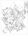
MECHANICAL DRAWINGS AND PARTS LISTS
t6
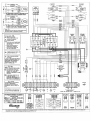
ELECTRICAL DIAGRAMS
20
WARRA\-TY
22
OPTIONS
M?00041-44
MP00045
PRO-GTW
PRO-GT4X
PRO-GTX
MP00007
MP00001
PRO-PI,
MPO0036
MPo0030 78-80
MP00035
#40 Dr;ve Chain
#50 reduction chain and sDrockets
Cast iron Pillow block bearinss on drire
Watemroof modfication
CoftosionDroof n1odifi cation
ExDlosion Droof modifi cation
I l5 Volt control circuil
Timer to Close
Senarate control Danel
Trollev ioist Discomect
DMI Trollev Assemblv
Minimun Dmth modifi cation
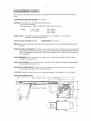
Upon delilery ol your MICANAN SYSTEMS healy-duty gearhead lrolley door operator, please inspect
the unit carefully for damage. Verify that operalor horcepover, vollage, phase and amperage correspond to
availabl€ power supply and door application. Check thai along wilh your operalor you have received the
following standard hddware.
1
x
OPEN/CLOSE/STOP 3-button control slation:
Ix
Set
Ix
Drive chain packase (door heisht x 2+
Ix
Trolley cdiage and 3/8 take-up boll assembly
Ix
Trollev rra.k end btacket
2
x
oftrolleytracks (door heighi + 2'6")
Trolley spreader bars
Faa-------rl{
Ix
Trolley arm assenbly
Ix
Set
ofwaming
signs
5'6" (1.65m) c/w
conoecting
link
PRO-GT heavy-duty gearhead troley operator is designed for standard lift ov€rhead scctional sarage
STANDARD OPERATOR WXIGHT: 95-150 Lbs.
MOTORT Continuous duty 1725 RPM induslrial rype moror.
Full overload protection
Horsepower rmge | 1/2HP, 3/4HP, lHP, 1.5lIP, 2HP(l-phase only)
ll5v I phase
230V l-phase
230V 3-phase
460V 3-phase
575V 3-phase
REDUCTION: Primary:Hear/
dury wolm gear reducer 20:1 (slandard)
Secondary: #41 chain and sprockets.
OUTPUT SHAFT SPEED: 86
RPM
BRAKf,: Solenoid actualed dllrn1
or 40:l reduction
DOOR SPEED: 10"/sccond
and brake shoe brakrng system to prevent coasting and naintain door
WIRING TYPf, (STANDARD): C-2 Wi.ing coffrant pressure on close, iromentary conlacl on open and
slop. Wired
1()
accepl reversing edge, Iadio control, photocells, loops and OPEN/CLOSE devices.
NOTE: Ifmomentary contact on close (82) winng is desied: Move "white" wire from t€rminal
#5 10 terninal #3.
TRANSFORMER: 24VAC control cicuit, supplies power to ddve control relays wilh 15VA power
available for extemal devices.
LIMIT ADJUSTMENT: 4 micro switches
tully adjustable screw tyle
lhar conlrol door travel. These
limii switches
are activated by
cams.
f,MERGtrNCY DTSCONNECT: Quick
r€lease disconnect door arm to allow person to disengage
operator ddve chain ftom door for nanual operatioD.
CLUTCH: Adjusiable in-line friction clulch to minimize danage to door operator, door or vehicles.
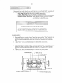
oPE:B+ABIIUETIQNS
IOIR HE161]I PLUS 4 FEET
(].4]NIMUM)
17-3/4.
Do not allow children to play
vith door.
Before installatjon, be sure that operaror is suited for b,pe ofdoor and applicalion
Connecl a revening device to Fevent entrapment if door is located near pedeslrian trafilc.
Place control device within clear sight ofthe door but ai a minimum distance ftom the door so that us€r
c:
ot Each moving door parts when opelating.
outdoor extemal devioes should have secwib' features io prevent unaulhorized operation of the door.
Never cross under
Press the
a
moYing dooi.
"OPEN" device or activate quick release disconnect device if
a
person is tapped under the
Do not use discoDnect mechanism or manualy operate door unless power has been electrically
Keep dooN p'operly maintained. Test door and senice rcgularly. Have a qualified service penon make
rcp^jts.
The
A
unnaintai
oMer o'
ed door
srste
could cause
i jrry
or deatlL
users musl undersland the safety and operation
installation manual be located close lo fhe door system-
ofdoor system. Insure that this
DO NOT INSTAIL THIS OPERATOR
BEFORE READING THIS MANUAL CAREFULLY.
Note:
I
.
INtallation of opelator must be done by a qualified installer. Door must be properly installed and
working smoothly. Remove all door locks pior to installation.
Instal control station away
s ft (1.s m)
2.
fion
fr
om
a[ moving door
parts,
vithitr sight of the door and
the smund.
Install enbapment waming
sip rcxt
to
co
rol station.
6y
7,'at
"tl
3.
Do Dor remo!e
merg{c}
rlease tag aftached lo discoonen bandle.
PRXPARATION:
1
Lay oul operator and tolley tracks on ground in fronr of door wilh door operator molor lacing
2.
Install track spacers evenly
3.
Install 3/8" take up bolt to carriage using two 3/8" hex nuls and lock washer provided.
4.
Slid€ trolley cariase tlroueh end ofrracks towards opentor wilh lake-up bolt facing operator.
5.
Install front idlcr assembly to the second set ofholes end of trolley tacks.
6.
10
irack assembly.
Bolt mil assanblyto ope.ator frane using four 3/8"x %"bolrs ald 3/8" senated hex nuts
proYided.
rRoNT
IDLER --1
TRACK SPAC:R
CARRIAGE ASSEMBLY
OPERATOR
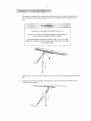
'7.
Atlach one end ofdrive chain to cariaee using connecting lint provided. Run chain around front
idler, over the track spacers, aJoud drive sprocket and cornect to take-up-bolt using coiiecling
link provided. Adjust take up boh so that chain sags approximately 3" (7.5 cn) al nidpoinl of
lracts. Remove linl(s from drive chain if necessary to nale proper adjustrnent.
TRACK SPACER
FRONT IDLER
CARRIAGF
CONNECTING
LINK
CONNECTING
LIN K
TAKE-UP BOLT
OPERATOR
DRIVE SFROCKET
8
WAI-L MOUNTING BRACKET AND OPERATOR INSTALLATIONI
NOTE: Trolley |?e operators should generally be mounted directly over the center of the door and the
trollcy tracks should olear the tracks by 2-112" (6.5 cm). However, if interfedng structures or other reasons
do not allow for centered mounting, it is possible 1o install it up 10 I 8" olT cenrer for to.sjon spring doors.
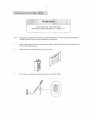
l.
Locate the center of door by measuring door width and mark a vertjcal line above the door.
2
Determine the highest pojnt of door travel by manually opainS the door. Using a carpenter's levet,
project a line ftotn where the top seclion of door reaches its highest poilt- Mdk the spot where this
line (high arc) intersecis with the vdlical Line drawn eariier.
3-
Mount a wood block oI angle iron to the wall above the door opening as shown below fte wall
mouting brackel has 3 holes for anchoring to vood btock or angle imn. Bncket should be centered
vith door md posiiioned so thal these holes are 2- I /2" (6-5 ffr) above the high arc line of door. Secure
vall mounting brackel using suilrble hardwarc.
4.
Whjle allowing motor to rest on floor, raise front end of track assembly and secwe (l'ui not tighlen) to
wall nounting brackets with 3/8" bolts and nuts providcd-
5
Sving the operato. and track assembly above the level ofthe door tacks and lempoEily secure in
place with .ope o' chain- Cmtully opcn dooi. Alisn operator and rails with cenler of door. Usins the
door as support, shin the operator so that there is 3" (7.5cn) clearance between door md botton of
operanrr. Tighten wall mounting brackel bolts.
I
6.
Oracet ftonr cejling or structure nr any ofthe 3/8" holes located on operalor
liame. For lracks over 14' long it is recommended to install braces to the lracks at 4'(1.2n) to 5'
{ l.<r I 0om opcrdror.
Insr,all hanging brackets
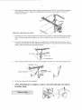
TROI,I,EY ARM TNSTAI,I,ATION
L
Manually close door 10 fully closedposition. Slide tiollcy cariage bwards ftont idler and latch trolley
am to ceiage spriry pin by pulling on rope. When installed the open side ofnotch should face the
2.
Using 3/8" bolts and nuts prcvided, align the mounling holes of straight am and cuNed aln so thal
pivol bolt on door bncket js in li.e with rhc top rollers of the door. Aljgt door bracket with centerline
ofdoor
ar
secue to door using suitabl€ hardware.
s
3.
Whe' properly installed the door arm should lean sliehdy away fron door when door is tully closed.
CARRIAGE
SLI!IN6 9RACKTT
\
4.
At this time, check
al1bo1ts for tishtness.
After installation is complete, remove red activation
breather plug.
10
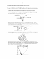
Adjustment of door travel is done by moving the limir cans on rhe threaded shaft. The posilion of
the 4linit switches are factory adjustcd drd should not be allered. lle limil switcnes are:
"op€n" limit switch: End ofdoor tmvel ln the tully open posilion
"Closed" timit snitch: End ofdoor travel in the tul1y closed position
"Adv.nced Open" limit switch:Used for ope'r/close devices or timer 1o closc fcatures
"Advmced Closed" Limit sryitch: Used to prevert reversing device frcm rcvcrsing
door whcn door is alnosl tuilv ctoscd.
To adiust door tavel:
1
Opetr cyclcr Dcprcss can1 plate and spin "Opeo" Limit cam away lrom "Open" limii switch ro
increase door travel or spin "Open" limit cam tovards the "Open'' lmn swilch to decrease
doorlravel. After each adjuslment ensure that cam plale fully engages in slots ofborh limit
2.
Adjusl Opcn" limil cam so rbat door slops al thc desired fully
open posilion.
Close cycle: Depress cam plate and spin "Closc" limil cam a\ay from "Close" limil switch to
increase door tavel or spin "Close" limit cam towards the "CLose" limil switch 10 decrease
doortravel. Aftcr each sdjustment ensure that cm platc tuily cngascs in slots ofboih limit
4
Adiust "Close" limil cam so that door srops at thc desired fully closed position.
OFEN LIMITCAM
cLosr
lrMtT swrTcH
ADVANCEB CLOSED LIMIT SWTCH
OP€N LIM'T SWTCH
ADVANCED OPEN LIMIT SWTC|I
lt
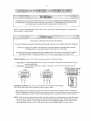
CONNECTION OF POWSR,SIPILY AND CONTROL STATION:::
Rcfer to electrical diagrams inside control box covel or ar rhe cnd oI ihis manual prior ro conneclio.
pos'cr supply or control station.
of
TO REDUCFJ TIIE RISK OF INJURY ORDEATII:
ALL ELECTR]CAI CONNECTIONS SIIOI]TD BE MADI] BY A QUAIIFIED SERVICE PERSON
DO NOT ATTEMPT TO MAKI] ELECTRICAI CONNECTIONS TO OPERA.TOR I]NLESS
POWER SUPPLY HAS BEEN DISCONNICTED AT FUSE BOX
OPER .TOR MUST BE CONNI]CTED IN ACCORDANCE TO LOC I ELECTzuCAI CODES
AND GROUN'DED TO GREEN GROU\D LUG LOCATED INSIDE CONTROI- BOX
POWER WIRING: Use 1-1/8" (2.85 cm) diam€tcr holes for ali power wnirg.
1.
2.
Siq{9 phale: Connect sinsle
phase powcr supply 10 leminals l- (line) and N (reutral) on thr€e pole
power tenninal strip.
Three-phase: Connect three phase power supply 1o lerminals
lcnninal
srrip.
Ll,
L2 and L3 on three pole power
r
3-PHAsE
LN
L1 L2
BU;oN
coNTRoL
@
3
Ut
CONTROL I'\TRING: Use 7/8" (2.22 cn) dimcler holes for all contol wiring.
Note:Do not run contol wjres andpowerw;cs in sane conduir.
- lnstall contol station wilhin clear sight ofdoor but away ftom all movilg pans ofdoor or hardware.
Install l-:nrrapmen! vaminS sign nexl1(r control slation. Connect 3 butlon (open/close/srop) push button
station to reminals 2,3, 4 and 5. Rcfer lo eleclrical diagtam for connecrion oftwo 3 butron slalion"
are nade. manually move door to mid position a'd, using the control
prcss
thc
"Open"
bulton
for
sevcral seconds and then press the "Stop" bufion. lf door did not
slation
NOTf,: Aiter electrical connections
move in conect dircclion veiry wiring contol station. Lollpbclg sp!!4!sr!, if door still mo\ es in
$rong direction reversc any two of ihe three inconins power supply leads to correct rotanor.
l2
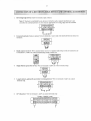
Reversing trdge d€vicc (must be nomally open conlacl)i
If the door is controlled by aly device or wited ifl such a manner that the door is no!
controlled by conslant pressure on closc then an appropriale relcrsing edge musi be installed
Note:
2.
Ext€rnal interlock: Removejumper between ielminals
1
and 2 and $.he interlock between these two
Radio cotrtrol receiv€r: Wirc standard radio recejvcr ro separate radio strip on s;dc of contol box or
to lerminals 7, 8 ard 9 on control lerminal sirip insid€ contlol box.
@
9
4. Siqle button
5.
open/close device: Wne to teminals 7 atd 8 on control
Loop detectors, photocells and other rev€ning devicesr Wire to tcminals 3
@
6
6.
fcmiml stip.
24
Volt pow€r: Wire to teminals
1 and
9 on contol teminal strip
CONTRO! TERI,iINAL STRIP
a2 @3 @ @5 @6 @7
aaaaoo
13
CLUTCH I
1
2.
34.
5.
Loosen bolts on clutch cover and slide cover towards molor to access clutch.
Loose. the two s€t screws on clulch adjusrmeot nut.
Rotate clutch nut countcrclockwise (loosen) until tbere is insuficient lension ro pennjt clutcb to drive
door. NOTE: Wlen adjusting nut. make sule to secure input shafl 1o not alow shaft to rotate when
lighlening or looseniog.ut.
Gradualy tighten clutch nut (adjust % tum 3t a time) unil rhe Gnsion is sufiicient to pemit clutch to
dnve door smood y but will allow clutch lo slip if door is obstructed. Ir should be possible to stop
moving door by hand if clutch is properly adjusted.
Tighlen lhe 2 set screvs after each time the unjt is tesied for clutch adjustme.t. Aftcr adjustnenl is
completed make sure set screws are locked in placc. Re-install clurch cover.
- Ihe brake adjustment js faclory sel and should only requiE minor adjustnenl after extensive use.
- Veriry hake adjushert by manually holding in solenoid plunger. wten brake is properly
adjusted, rhe brake shoe pads should make complete oonlacl wiih bmke drum wilh sufficient brake
spring tension to slop and main€in door when solenoid is de-energized. wtren solenoid is
energized, brake shoes should rclease fron drun with su{Iicicnt clearance to avoid conlncl
betiveen shoes and drum.
- To adjust brake tension, dghten (lo increase) or loosen (to dec'ease) nylon lock lut on brake
spring bolt. ObseNe sole.oid during electrical testing of brake. Brakc sprirs lension Dust be
adiusted so that solenoid should pull and rc1ease smoothly and quietly. Too rnuch or too litde
tension on bralre sp ns nay cause solenoid to bum out.
To adiust individual brale shoes, loosen nut on brake shoe adjustnent boh and adjusl bolt. W1len
properly adjusted. lhere should be a snall cleara'ce b€tween adjustnenl bolt and solenoid bracket
when solenoid is de-cnergized. wlen solenoid is energized, bmke shoes should move away lrom
dnm vilh sufilciert clearaflc€ to avoid friclio, betwe€n bralc shoe pad and drum. ,^fler
adjustme.ts are nade be sure 10 tighten nuts on bmke shoe adjushenlbolls.
l4
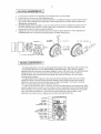
The operator is equipped with a quick releas€ discomect system to manually operate door iD
case of emergency. This feature should not be used to manua y operate a maltunctioning
TO REDUCE TIIE RISK OF INJTIRY OR DEATH:
DO NOT ATTEMPT TO USE EMERGENCY DISCONNECT
SYSTEM WHILE OPERATOR IS RUNNING.
TO AVOID BEING STRUCK BY DOOR ARM, DO NOT STAND
DIRECTLY IJNDER TIIE RELEASE ARM WHEN PULLING TIIE
RELEASE CORD.
l.
Pull the rcl€ase cord dowDwards to disconnect tolley anD ftom cariage and manualy operate
2.
To recoonect door afln to caniage,
troney cariage spring pin.
pul energency
release oord and &'insert trolley arm to
15
TO REDUCE TTIE RISK OF INTJRY OR DEATH:
DO NOT ATTEMPT TO SERVICE TIIE OPERATOR IINLESS
POWER SIJPPLY HAS BEEN DISCONNECTED
lf
Inspect manual fiuction of the door every 3-months. Mate sure that door runs snoothly
door does not maDualy op€n or close fr€ely, have a qualified serr'ice penon mal(e repain Do
not attenpt to eleclr'icaIy operate a malfirnctioni4 door.
Everv 3 montls:
1.
Veriry $at door area is kept olea!. Remove any obstructioas that would prevent proper
door operation.
2. Check for ary excessive slack in chains. lfchah adjustnent is requned veiry and
adjustlimit swifches, if ne.essary.
3. veriry and adjust clutch and brake (Do not lubricate).
4. Lubricale chajns, beating" and timit sbafi.
5. Veriry that motor, solenoid and operator ruff snootbly and quiedy. Verify dlat
carriage runs smoolbly on tmcks-
Everv 6 months:
1. veriry dghtuess ofal fastenerc and set screvs.
2. Veri& that operator is properly secured.
3. hspect muual disconnect.
Everv 12 moflths:
L Perfom a cornplete service check.
2. Verify that iiside ofcontrol box is clean aDd tlat grounding wires, terminations a
po$tr !f,minariotrs do nor sbow sigrls olconosioD.
3. Verify tielhess of all terminal strip scre\i6 and electrical comections.
4. Verify power supplX voltage ofinput teminals dwing operation.
5. Vdfy tlat culfetri consumptior ofoperator corresponds to nameplare infomatiotr
O
z
o
F
2 ndo
, d'!''
n t:
tJ.l
F >Erc(
HIiF
pe ti n
F
a
z r!l!d
z o ;
(-)
d.
!t nFi
n
z
,'r
\*f,l,BsN
?
s
z
:
q*=3=*
iY-sn h
o1
!
I
:
rtE
\a-a7
,&
I
il'A
lim
-%\
=\'iza
\s/
Edl,'f"'
ffi-'
w /
\/rcd
t1
Replacement parts list PRO-GT
GEARREOUCEP CH 55 20 r
(r/2 lr4 rhP)
2A
5
:T TI]NNEL FP,AME
MSIOO4T
SOL,COVER GEARHEAD MS]0032
12
13
GEARHEAD FRAME SUPPORT C.
IDX2'OD
FLANGE BEARINC
f
1
L tvt
T sHAFr 313-1/2 x
I
75"
BRONZE T-BIJSH NG 3/3' D
M LO STEEL BUSH NG9/32IDX 13/32ODX1
5 REDI.65 LTNKS
'16 I#70 REOI
KEYWAY 1/4'SO. X 1
LG
'4"
NG
H.H. SLOTTED SELF ROUND
RBBED HEXNUT3/3" 1€UNC
. 70. 30) rMsr0033)
SPROCKET410B12 X 3/3
sPRocKET4loB23x1' bore
DOUBLE NUI FOR L M.SW
LIMIT SWTCH DOL]BLE SPACER 3/4'LONG
+410 ROLLER CHAIN 69 L]NKS C^vCON. LINK (FOR REDUCER #70)
CAM PLATE COMPRESSON SPR NG { 1731D, O32GX.55L)
BRAKECOMPRESSION SPR NG (5/16'D.OsG 2 5OL)
1
12
rH
51
R
PHILLLPS MACN]NE SCREW4 40
H PHILLIPS MACHINE SCREW 6.32
R.H. PHTLLLPS MACNINE SCREW1G32
59
UNCXI'I/2
UNC
xI
UNFxs/e'
llE^ HEAO BOLT l/4-20lJNCr4'(Nottul thread)
N.1t. BOLT 5t6a13UNC X 3/4 LONG
HEX NYLON LOCK NI]-I S32UNC
RIBBED HEX NUT 1/A!OUNC
hEXNEADBOLTS/3 16UNC' I 1/4"{Furlhrcad)
t\,1800013
LIM T SWTCN {STANOARO)
KEYWAY3/16sO.r 1 1/4 LONG
HD/Gr 1' X
KEYSTOCK3116'X1-3/4
LONG
FRAME SUPPORT SHAFT 3/4'X 6^ LONG
IN.L NE CLUTCH SUPFORT SHAFI
10-711 6
laLoaa
loE
o
FA-"*A--_.l
la
6MPDCEo{ e
t^,,.*",.,*.,'*"t
lA dEATEhND
RoH
I
lmn
I nom PELAYdT
I
aD
I
N
soENo,D (F
Rr hF,N
rRNsoRxEP
@rc^!E)
I
I
I
I
I
I
t-dmur"*.^R"61Et
I
ffiRLATE MER^OE
t*-""*,*""**"t
I
t i1irllj11
-J
G;;;;;;;;)
l-r1T-"*'"'
J
fF,tr*qrr!!!!!l!$. I
r , i *c ni.Euv
utui ffin
pFd'rpFr FxduF rHF
FFTFXF
'q
I ME w,RE FRoi EM,N.r.
I sD corNE.r ro oiE EiD oF
In E.EuYdoo R D.
I
I
I
I
t1rr1111
,
I
I
I
I
?
_J
ry'r
lfl
tB-
6 /6
rea
I
I
I
I i
"*-
",.
H Nd (*.u*br..'NFl
ar.oNsNr
-\
#r.'DF
DEDMi
DFr
'rFqFFh
*rE
{rRE FRd
A
I
I
lro"**,*,*.*,**
| - oGE h2 wirNd
I
I
I -r-
I
I
I
nF
Erfl'Nr
'5
pFNnrF
:
t a1.-tji!rr'*it
f--
A
L
*;; --l
l F FF.F Frr^PrFr
|
I PRoE.nd sEris *HFN B,
I
I mdEM*' cNrun {RM s I
[e."
r-;;;;;)
I
EE
us
tuR
F
+
/
l.
J\
rD coNNknos
I
)
lL
1234567A9
r15v
c
0R 203/230 vA..
r
PHrsE
3.
H2
*MICANAN
w
rHE E!:oRMAroN coNraNED
HERETN
E rBoFRrErlFfio
!!!A!A!ll
c dD
s
HALL
Nor sE
RE
FSoDUqE!
!3
Dl
!!!!!!
a3
qlEalQ3
l
qEsE!
!a
faFAcrm.
cElrldlE! ls€R
P
t""rT
-rLH-illoum--r-
sftH
t''-'---/
rA
I
-----__-
l,'-----r{o
*
"
I ffs!m^
--1
N.o
I
l-*
!!ra,
--J
I
Yl
t,,_
o
l-ffir
I
t-
d:E
A
E
Hffi
lfl
I I
EtwH
Er{
ooNENreY cdmAcr wrRrM
rM*,a. I
tL5?
l*
rs
TA-N
It4)t^1
I I lr
rll(
)l
\pt>
+
1
5.
?34s
9
PHASE WIRING DIAGRAM
iis30o:ww
HElf Ll.llEr. ..... ..
qiNADA: L (877) 80€- 6
rEc.H.
--.
MIGANAN
nlE
NF
v
03!AIl!! !a!D!!ED
3E3E!X
!!l!0t!1EI43! t0
Mi
cMN srsrEHs
Nc. AlA
S!,!!L
lqt
sE REh oouc
p
0R
D
scLos ED 0R
l
and workmanship are free from defects for a period of
two years Fom the date of irlvoice. Materials rciumed to Micanan deemed defeclive after exmination
will bc relumed at lhe oplionofMicanan u'ith repaired, new or re manufacnrred pats.
MICANAN SYSTEMS walTan|s rhat naterials
MICANAN SYSTEMS will nol be responsible for dy extra charges incured ;n the process of retuming
defective material. All rerumed material must be receivedpre paid or itvillnot bc acceptcd
This wananty is limiled, and in lieu ofall other warranty exprcssed or implicd- Thcre is
liability duc on rhe pan of lhe seller.
!o expressed
luilGAllAll
Commer.ial Daor Opening Devices
MICANAN SYSTEMS INC.
HEAD OFFICE
1380 St-Regis
PHOENLX
1236 W.
Dorvrl, Qu€bec
Canada, HgP
Southen Ave.
Suite 104
2I5
2885 N. Berkelcy Lake Rd.
Strit€ 7
Duluth, Ca
r;sA
TEL:
ATLANTA
85282
usA 30096
(51.1) 822-1116
Tf,L: (480) ss7-0070
TEL: (678) 584-2543
l-877-888-1116
FA-X: (s14) 822-11r8
1-888-816-858,1
(480) 557-8488
1-800-798-2543
FA*
rA.*
(678) s84-2s44
CHTCAGO
706 R€mingtotr Rd.
Suite
Schaumburg,
usA
I1
60173
TEL.: (847) 83t-8303
1-800-670-8303
FAx: (847) E39-8308