1
PA-CP Series
Powered Mixer
USER GUIDE
Publication AP4956
Limited One Year Warranty
This product is warranted to be free from defects in materials or workmanship for period of
one year from the date of purchase by the original owner.
To ensure a high level of performance and reliability for which this equipment has been
designed and manufactured, read this User Guide before operating.
In the event of a failure, notify and return the defective unit to ALLEN & HEATH Limited or
its authorised agent as soon as possible for repair under warranty subject to the following
conditions
Conditions Of Warranty
1. The equipment has been installed and operated in accordance with the instructions in
this User Guide.
2. The equipment has not been subject to misuse either intended or accidental, neglect,
or alteration other than as described in the User Guide or Service Manual, or approved
by ALLEN & HEATH.
3. Any necessary adjustment, alteration or repair has been carried out by ALLEN &
HEATH or its authorised agent.
4. This warranty does not cover fader wear and tear.
5. The defective unit is to be returned carriage prepaid to ALLEN & HEATH or its
authorised agent with proof of purchase.
6. Units returned should be packed to avoid transit damage.
In certain territories the terms may vary. Check with your ALLEN & HEATH agent for any
additional warranty which may apply.
This product complies with the European Electromagnetic
Compatibility directives 89/336/EEC & 92/31/EEC and the
European Low Voltage Directives 73/23/EEC & 93/68/EEC.
This product has been tested to EN55103 Parts 1 & 2 1996 for use in
Environments E1, E2, E3, and E4 to demonstrate compliance with the
protection requirements in the European EMC directive 89/336/EEC. During
some tests the specified performance figures of the product were affected. This
is considered permissible and the product has been passed as acceptable for
its intended use.
Allen & Heath has a strict policy of ensuring all products are tested to the latest
safety and EMC standards. Customers requiring more information about EMC
and safety issues can contact Allen & Heath.
NOTE: Any changes or modifications to the console not approved by Allen &
Heath could void the compliance of the console and therefore the users
authority to operate it.
PA-CP Series User Guide AP4956 Issue 4
Copyright © 2005 Allen & Heath Limited. All rights reserved
Whilst we believe the information in this guide to be reliable we do not assume
responsibility for inaccuracies. We also reserve the right to make changes in
the interest of further product development.
Allen & Heath Limited
Kernick Industrial Estate, Penryn, Cornwall, TR10 9LU, UK
http://www.allen-heath.com
2
PA-CP User Guide
Important Safety Instructions – Read First
Read instructions:
Retain these safety and operating instructions for future reference. Heed all
warnings printed here and on the console. Follow the operating instructions
printed in this User Guide.
Do not open:
There are no user serviceable parts inside.
competent technical personnel only.
Power sources:
Connect the console to mains power only of the type described in this User
Guide and marked on the rear panel. The power source must provide a good
ground connection.
Power cord:
Use the power cord with sealed mains plug appropriate for your local mains
supply as provided with the console. If the provided plug does not fit into your
outlet consult your service agent. Route the power cord so that it is not likely to
be walked on, stretched or pinched by items placed upon or against it.
Grounding:
Do not defeat the grounding and polarisation means of the power cord plug.
Do not remove or tamper with the ground connection in the power cord.
Ventilation:
Do not obstruct the ventilation slots or position the console where the air flow
required for ventilation is impeded. If the console is to be operated in a rack
unit or flightcase ensure that it is constructed to allow adequate ventilation.
Moisture:
To reduce the risk of fire or electric shock do not expose the console to rain or
moisture or use it in damp or wet conditions. Do not place containers of liquids
on it which might spill into any openings.
Heat:
Do not locate the console in a place subject to excessive heat or direct sunlight
as this could be a fire hazard. Locate the console away from any equipment
which produces heat such as power supplies, power amplifiers and heaters.
Environment:
Protect from excessive dirt, dust, heat and vibration when operating and
storing. Avoid tobacco ash, drinks spillage, and smoke, especially that
associated with smoke machines.
Handling:
To prevent damage to the controls and cosmetics avoid placing heavy objects
on the control surface, scratching the surface with sharp objects, or rough
handling and vibration. Protect the controls from damage during transit. Use
adequate packing if you need to ship the unit. To avoid injury to yourself or
damage to the equipment take care when lifting, moving or carrying the unit.
Servicing:
Switch off the equipment and unplug the power cord immediately if it is
exposed to moisture, spilled liquid, objects fallen into the openings, the power
cord or plug become damaged, during lightening storms, or if smoke, odour or
noise is noticed. Refer servicing to qualified technical personnel only.
Installation:
Install the console in accordance with the instructions printed in this User
Guide. Do not connect the output of power amplifiers directly to the console.
Use audio connectors and plugs only for their intended purpose.
Refer any service work to
Important Mains Plug Wiring Instructions
The console is supplied with a moulded mains plug fitted to the AC mains
power lead. Follow the instructions below if the mains plug has to be replaced.
The wire which is coloured Green/Yellow or Green must be connected to the
terminal in the plug which is marked with the letter E or with the Earth symbol.
This appliance must be earthed.
The wire which is coloured Blue or White must be connected to the terminal in
the plug which is marked with the letter N.
The wire which is coloured Brown or Black must be connected to the terminal
in the plug which is marked with the letter L.
PA-CP User Guide
3
Introduction
Welcome to the Allen & Heath PA Series professional audio mixing system. This user guide describes
the functions of the powered PA-CP models and also provides tips and reference information to help
you get the best from your system. We know you want to get started right away. For this reason we
have kept the guide concise and to the point. We recommend you read it through first. However, if
even that is too much then at least read the QUICK START page before you plug up and go. For
further information on the basic principles of audio system engineering and mixing technique please
refer to one of the specialist publications available from bookshops and audio equipment dealers.
Further training is available using the many seminars and courses available in audio engineering and
related subjects.
We are able to offer further product support through our world-wide network of approved dealers and
service agents. You can also access our Web site on the Internet for full company and product
information. To help us provide the most efficient service please keep a record of your console serial
number, and date and place of purchase to be quoted in any communication regarding this product.
The guide is structured for all levels of user. A brief description
of the controls and technical reference information is available
for experienced engineers who want to get started quickly. For
those of you who want to learn more about the basics of live
sound engineering we have included useful blocks of
information and tips.
Description
Control and connector functions are briefly
described together with related technical specifications.
Information Where you see this symbol you will find an
explanation or background information on a particular topic.
☺
Tips for the user Where you see this symbol you will find
tips and information on using a particular function.
Warnings For your own safety and to prevent damage
to equipment make sure you read and adhere to all warnings.
Model
Serial Number
Place of Purchase
Date of Purchase
4
PA-CP User Guide
Contents
Information
Phantom power................................................13
Balanced and unbalanced connections .........13
The mic preamp ...............................................14
The HPF (high pass filter) ................................14
The mono channel equaliser ...........................15
Pre and post-fade aux sends...........................16
Effects sends....................................................16
Foldback sends................................................16
The dB fader scale ...........................................17
The dB explained .............................................17
PFL explained ..................................................17
The stereo channel equaliser ..........................19
Wet and dry effects signals .............................20
Effects processing engines .............................22
AFL explained ..................................................24
Gain structure...................................................24
Sub bass speakers ..........................................25
The amplifier design philosophy .....................26
Constant power explained...............................26
Front-of-house and foldback monitors............27
Different amplifier configurations.....................27
Why the parametric output equaliser ..............27
TRS jack ...........................................................28
Line level...........................................................28
Impedance balanced outputs .........................28
SPDIF explained...............................................30
Main Topics
Important Safety Instructions ............3
Overview ............................................6
The PA Range....................................7
Key Features......................................7
Panel Layout......................................8
Quick Start.........................................9
Installing the Console......................10
Mains Power and Earthing ..............11
Cable and Connector Information...12
The MONO Channel ........................13
The Mono Equaliser ........................15
The STEREO Channel .....................18
The Stereo Equaliser .......................19
☺
Tips for the user
Working with different channel sources..........13
Setting the channel gain ..................................13
Using the HPF (high pass filter) ......................14
Using the channel equaliser ............................15
Using more than one effects unit ....................16
Setting up a foldback monitor mix ..................16
Using channel pan ...........................................17
Using the channel faders.................................17
Using PFL .........................................................17
Using the stereo channels ...............................18
Mixing two stereo signals into the channel.....18
Sending ST1(3) direct to LR ............................18
Using the stereo channel equaliser.................19
Effects in the monitors .....................................21
Using the FX channel PFL ...............................21
Using the effects ..............................................22
Checking the gain structure ............................24
Using PFL and AFL ..........................................25
Using the AB output equalisers.......................27
Using line level signals ....................................28
Using balanced or unbalanced connections..28
Working with powered speakers .....................29
Choosing headphones ....................................29
Connecting SPDIF ...........................................30
Patching in speaker processors......................30
No amplifier output? ........................................31
How to check speaker polarity ........................31
PA-CP User Guide
The EFFECTS Channel ...................20
MIDI and the Effects ........................23
The MASTER Controls.....................24
The AMPLIFIERS .............................26
Amplifier Source Select ...................27
AB Output Equaliser........................27
The MASTER Connectors ...............28
Specifications ..................................32
System Block Diagram....................33
Fitting the PA12-CP Rack Ears........34
Cue Sheet........................................35
5
Overview
PA Series consoles provide all the tools you need to run a small PA system in an easy ‘walk up and
go’ format. You simply plug in your microphone and line sources and connect to the speakers. All the
control and processing you need to run a small PA system is built into the console.
Two powered models are available. The PA12-CP has 8 mono and 2 dual stereo channels. The
PA20-CP has 16 mono and 2 dual stereo channels. Both are portable and include protective side
trims and front carry handles. The PA12-CP can be mounted in a standard 19” rack or plinth by
removing its trims and fitting optional rack ears provided.
The two amplifiers can be configured in several different ways according to your PA requirements. For
example, you may run a stereo house system without monitors, or a mono system with additional
musicians monitor speaker, or you may connect to externally powered house speakers and use the
internal amplifiers for two independent monitor speakers. The additional mono line output can be
used, for example, to feed a sub bass amplifier/speaker system or another listening zone.
The power amplifier is without doubt the most critical device in the audio signal path. It converts a
reservoir of power derived from the mains supply into amplified sound. The PA-CP amplifier is a third
generation design that has been rigorously field tested both for absolute reliability and sound quality. It
uses a solid, no-nonsense 1.6kW linear power supply and bi-polar assisted MOSFET Class AB
amplifier design. The unique Allen & Heath constant power system ensures that all the available power
is converted into useable speaker power so achieving the full 500W per side into 4 ohms or 8 ohms.
Full protection is provided including isolating relays, short circuit and over current protection, output
sensing clip limiter, and twin fan thermal management.
We recognise the importance of accurate equalisation both for creative sound processing and for
dealing with problems such as feedback and room resonance. The channel strip features a powerful 4
band EQ with two mids, one with swept frequency. We have chosen to include 4 band semiparametric rather than traditional graphic EQ on the amplifier channels. These provide far greater
accuracy and therefore less colouration of the sound. Our ‘EQ Visualiser’ software is available to help
you learn how the parametric controls affect the frequency response.
Years of designing mixers and listening to our customers has resulted in a control surface that presents
a well thought out set of functions including many innovative touches that make the job of mixing a
simple pleasure. Notable features include individual phantom power, space saving dual stereo inputs,
standby and BGM (background music) modes, built-in digital effects processor, lamp connector,
selectable sub filter, recording source selector and even an SPDIF digital output.
The name Allen & Heath is well regarded in the professional audio world. The standards applied to our
top end consoles also apply to the PA Series. High grade circuits and components, 100mm Alps
faders, individual vertical circuit cards with sealed potentiometers nutted to the panel, solid grounding
with internal copper buss and steel chassis construction are just a few of the qualities that put this
powered mixer into a class of its own. Our objective was to provide a truly professional solution for
small system mixing. We hope you enjoy using your PA Series console.
6
PA-CP User Guide
The Range
PA20-CP
16 mono MIC/LINE channels
2 dual stereo LINE channels
PA12-CP
8 mono MIC/LINE channels
2 dual stereo LINE channels
Both Models
Accessories
LR main output
Mono output summed from LR
4 Auxes – 2 pre-fade foldback, 1 post-fade aux, 1 post-fade effects
External stereo effects input to sum with internal effects
AB amplifiers with slave output and amplifier breakpoint inputs
2-Track input for monitor and BGM replay
2-Track recording with analogue and digital SPDIF outputs
Headphones monitor
Rack Ears
A pair of metal ears to replace the
trims and fix the console into a 19”
rack or custom furniture.
PA EQ Visualiser
Runs on a PC to display how the
parametric output EQ affects the
frequency response
Key Features
•
Constant power amplifier for 2x 500W into 4 or 8 ohms
•
Semi-parametric output EQ for more accurate frequency control
•
4 Band channel EQ with swept high mid and 250Hz low mid
•
Built-in stereo digital effects with external summing and MIDI control
•
SPDIF digital audio output
•
Dual stereo channels for summed or 4 independent inputs
•
Standby and post-LR BGM operating modes
•
Switchable sub bass filter on mono output
•
Individual +48V phantom power switching
•
100mm faders, mutes and inserts throughout
PA-CP User Guide
AL4061 Lamp
Plug-in XLR gooseneck lamp to
illuminate the control surface
7
5
0
20 -5
30
-5 10
0
MIC
LINE
-10 -5
10
40
50
63 25
-5 10
0
20 -5
30
0
MIC
LINE
-10 -5
50
63 25
100Hz
12kHz
10
40
1k5
+15
600
3k
0
20 -5
30
0
MIC
LINE
-10 -5
-10
10
40
-20
50
-30
63 25
100Hz
12kHz
-15
-5 10
7k
-15
+15
250Hz
-15
1k5
+15
600
3k
350Hz
7k
-15
+15
1k5
3k
600
-10
60Hz
-15
+15
-15
+6
OO
PAN
=
+15
OO
+6
-10
+10
-10
+10
parametric output equaliser
500
100
10k
1k5
MIN
20k
-10
MAX
1k
1k
5k
SPK
OFF
L FB1 FB1
TMP
7k
2k5
200
+10
2k5
3
R L+R FB2
SPK
OFF
SIG
LIM
20Hz
200
120Hz
2k
500Hz
10k
1k5
20k
-10
+10
-10
+10
-10
+10
-10
+10
10
OO
-15
+15
-15
-10
+15
MIN
MAX
0
3
60Hz
-15
+15
-15
OO
10
OO
+6
7
+15
+6
OO
+6
OO
+6
+6
OO
+6
OO
+6
=
+6
+6
OO
+6
OO
PAN
OO
REVERB
OO
+6
OO
PAN
+10
30
AUX
OO
+6
OO
10k
12kHz
60Hz
OO
+6
OO
+6
500Hz
FB2
AUX
OO
+15
-15
+6
OO
+6
OO
2k
FB1
FB2
AUX
12kHz
-15
+15
2k5
SIG
5
-30
10
OO
7k
5k
+15
60Hz
FB1
FB2
-15
+15
60Hz
FB1
7k
350Hz
1k
LIM
0
-20
5
1k
11-12
LR
-10
0
-20
2k5
200
120Hz
70
+15
250Hz
-15
200
-10
-15
+15
100
20Hz
12kHz
250Hz
-15
10
OO
9-10
LR
100Hz
-30
350Hz
30
5
-30
10
500
0
-20
5
OO
70
-10
0
+6
OO
=
+6
OO
+6
OO
=
=
+6
OO
+6
EFFECTS
HALL 1
DELAY 1
HALL 2
DELAY 2
ROOM 1
CH / RM 1
ROOM 2
CH / RM 2
ROOM 3
CHORUS
PLATE 1
FLANGER
PLATE 2
ROTARY
PLATE 3
PHASER
POST-LR
PRE-LR
TO
MIN
MAX
OO
+6
POST-LR FADER
L
R
PK !
L
PK !
R
L
PK !
R
L
R
PK !
R
PK !
STEREO
8
L
PK !
STEREO
STEREO
PA-CP User Guide
Quick Start
1 Ensure your safety First read and understand the Important Safety Instructions printed earlier.
Make sure that all your equipment is set for your local mains supply voltage and correctly grounded to
ensure your safety. Check that the console rear panel ON/OFF switch is in its out position (off). Plug in
the mains power using the power cord supplied with the console. Do not turn anything on until you
have checked your wiring and control settings. Also make sure the ventilation slots on the front and
rear are not obstructed in any way.
2 Set all controls to their starting position Set the AMPLIFIER levels, channel FADERS, GAINS,
FB, AUX and FX sends, MONO OUT and 2TRK to LR level controls minimum (anti-clockwise). Set PAN
and all EQ controls centre. Set all switches up or out. Make sure the 48V switches next to the MIC
inputs are in the up position. Check that the recessed panel switches are up (flush with the panel).
Use a pen or pointed object to operate these. Starting with the controls set in this way prevents any
unexpected surprises when you switch the system on.
3 Configure the system Decide how you wish to use the amplifiers. Set the AMP A and B source
switches for stereo, mono + monitor, or 2x monitor operation. These switches are recessed to avoid
accidental operation once set. A good starting point is the default stereo operation (both switches up).
4 Connect the loudspeakers Check that the loudspeaker cables are correctly connected at the
speaker end. Plug your speakers into the rear panel A and B Speakon™ connectors. Push the plugs
into the sockets and twist them into their locked position. Use 4 ohm or 8 ohm speakers. Do not use
bridged operation. Set the rear panel CONSTANT POWER slide switch to the correct position for the
speakers used.
5 Plug in a music source Plug a CD player or similar test source into the ST3 inputs on the last
stereo channel. Check that the recessed switch below its GAIN control is flush with the panel. This
routes the ST3 input to the stereo channel.
6 Turn the system on Press the ON/OFF switch to apply power to the console. The front panel
blue power LED lights and you should hear the speaker relays click in after one or two seconds. You
may also hear air movement as the internal fans start up. The meters and several other LED indicators
may pulse as the power rails stabilise. This is quite normal.
7
Adjust the levels and route the signal to the outputs Press the stereo channel PFL button.
Adjust the ST3 GAIN control until the main meters read around ‘0’. Release PFL and raise the channel
and LR faders to their ‘0’ positions. Next, gradually raise the AMP A and B LEV trim controls. You
should hear the music in the speakers. With the meters averaging ‘0’ to ‘+6’ adjust the amplifier LEV
trimmers for the loudest volume you expect from the system. That gets the gain structure about right.
8
Experiment with the system Use the music source to experiment with the EQ and internal
effects. Plug a microphone into one of the mono channels. Make sure the channel is muted when you
plug or unplug microphones, or when you switch 48V phantom power on or off. To find out more
about each control continue to read through the rest of this guide. HAPPY MIXING !
Important Note about Hearing :
!
1
To avoid damage to your
hearing do not operate any sound system at excessively high volume. This
also applies to any close-to-ear monitoring such as headphones and IEM.
Continued exposure to high volume sound can cause frequency selective or
wide range hearing loss.
4
6
PA-CP User Guide
9
Installing the Console
The PA Series is portable and designed for stand alone operation. The smaller PA12-CP model can
also be 19” rack mounted by replacing the trims with the rack ears provided. Either way, ensure
adequate ventilation around the unit and heed all warnings regarding mains power safety and earthing.
1 Carry Handle Metal handle for lifting and carrying the
console. The weight is centrally distributed. Lift the console by
holding the handle securely in the middle. To prevent damage
to the controls, carry it with the control surface away from you.
The console is necessarily heavy due to the high
power amplifiers built in. To avoid injury to yourself or
damage to the equipment always ensure you are correctly
positioned and grip securely when lifting, moving or
transporting the unit.
2 Feet Protective rubber feet are fitted to both the base and
the rear of the console so that it can be positioned for stand
alone operation or on the floor while it is being carried. This
avoids damage to the mounting surface and console parts.
3 Front and Side Trims The front armrest, carry handle and
side trims offer both protection and style to the console. They
can be easily removed for fitting the metal ears provided when
you want to permanently mount the console in a 19” rack or
plinth. This option only applies to the smaller PA12-CP model.
Instructions for fitting the rack ears is provided later in this user
guide. The console can be rack mounted in either of two
positions as described below.
4 Rack Position 1 Shows the ears fitted for top of rack
mounting. The controls are angled upwards above the rack for
easier access during operation. This position may also be
preferred when the console is mounted in a desk or other
furniture. 10U rack space is required. Allow additional space
for access to the rear panel connectors.
5 Rack Position 2 Shows the ears fitted for front of rack
mounting. The controls are flush with the rack and connectors
angled slightly back. 11U rack space is required. This allows
space for cables to be routed into the rack, and for the console
lamp to be accessed.
6 Ventilation and Cooling The console uses a twin fan
thermal management system to control the operating
temperature of the built-in 1kW power amplifiers. Air is drawn
in from the front and expelled from the rear. The fans run at
low speed when cool, medium speed on reaching 35 degrees
C, and fast speed at 50 degrees C. The unit shuts down safely
in thermal protect mode in the unlikely event that excessive
temperature is reached.
Do not obstruct the front or rear ventilation slots or
position the console where air flow required for ventilation
is impeded. The console must not be operated in any carry
or flight case that obstructs these slots. Ensure adequate
air flow when rack or plinth mounting the console.
7 Console Lamp Plug in a 4-pin XLR 12V gooseneck lamp
designed for this purpose.
The right angled type is
recommended. A low or high intensity bulb up to 400mA
maximum can be used. Only one lamp may be connected.
10
PA-CP User Guide
Mains Power and Earthing
Connecting Mains Power
Read the SAFETY INSTRUCTIONS printed at the front of this
user guide and on the rear panel. The power supply is wired for the local voltage required. Check that
the correct mains lead with moulded plug has been supplied with your console, and that the marked
voltage matches your local supply. Ensure that the IEC mains plug is pressed fully into the rear panel
socket before switching on.
To avoid any unexpected audible clicks or thumps
turn connected power amplifiers down or off before
switching the console or any other signal equipment on or
off. The built-in amplifiers include an automatic turn on delay
for this purpose.
CAUTION
RISK OF ELECTRIC SHOCK
DO NOT OPEN
AVIS: RISQUE DE CHOC ELECTRIQUE - NE PAS OUVRIR.
SERIAL NUMBER
DO NOT OBSTRUCT VENTILATION OPENINGS.
NO USER SERVICEABLE PARTS INSIDE.
WARNING: TO REDUCE THE RISK OF ELECTRIC SHOCK
DO NOT EXPOSE THIS APPARATUS TO RAIN OR MOISTURE.
THIS APPARATUS MUST BE EARTHED BY THE POWER CORD.
RISK OF HAZARDOUS ENERGY! MAKE PROPER SPEAKER CONN
SEE OPERATING MANUAL BEFORE USING.
MAINS INPUT
ON/OFF
I
0
V AC ~ 47- 63 Hz
1600W MAX
CAUTION: FOR CONTINUED PROTECTION AGAINST RISK OF FIRE REPLACE F
ATTENTION: REMPLACER LE FUSIBLE AVEC UN DES MEMES CARACTERISTIQ
FUSE 100-240V T10A L
CONSTANT POWER SWITCH
4 OHMS
ENGINEERED IN ENGLAND BY ALLEN & HEATH Ltd.
8 OHMS
Switching On Press the rear panel ON/OFF switch in. The
front panel blue power LED lights. You should hear the
speaker relays switching in after a second or two. This avoids
audible thumps while the circuits stabilise. The front panel SPK
OFF indicators light while the speakers are isolated. You may
also hear air movement as the internal fans start up. The
meters and several other LED indicators may pulse briefly.
This is quite normal.
Switching Off Release the rear panel ON/OFF switch. The
relays switch off instantly to protect the speakers from any
switch off thumps.
Earthing
The connection to earth (ground) in an audio system is important for two reasons:
SAFETY to protect the operator from high voltage electric shock, and AUDIO PERFORMANCE to shield
the audio from interference.
For safety it is important that all equipment earths are connected to mains earth so that exposed metal
parts are prevented from carrying high voltage which can injure or even kill the operator. It is
recommended that the system engineer check the continuity of the safety earth from all points in the
system including microphone and instrument metal, equipment cases, rack frames, and so on.
The same earth is also used to shield audio cables from external interference such as the hum fields
associated with power transformers, lighting dimmer buzz, and computer radiation. Problems arise
when the signal sees more than one path to mains earth. An ‘earth loop’ (ground loop) results causing
current to flow between the different earth paths. This condition is usually detected as a mains
frequency audible hum or buzz.
To ensure safe and trouble-free operation we recommend the following:
•
Have your mains system checked by a qualified electrician If the supply earthing is solid to
start with you are less likely to experience problems.
•
Do not remove the earth connection from the console mains plug The console chassis is
connected to mains earth through the power cable to ensure your safety. Audio 0V is connected to
the console chassis internally.
•
Deal with ground loops Should you experience hum or buzz caused by earth loops, check first
that each piece of equipment has its own separate path to earth. If so, operate earth lift switches
on connected equipment in accordance with the instruction manuals. Alternatively, disconnect the
cable screen at the destination end only. This breaks the offending loop while still maintaining the
signal shielding down the length of the cable.
•
Use low impedance sources such as microphones and line level equipment rated at 200 ohms or
less to reduce susceptibility to interference. For high impedance instruments use DI (direct inject)
boxes such as those readily available from most music equipment suppliers. The console outputs
are designed to operate at very low impedance to minimise interference problems.
•
Use balanced connections for the microphone inputs and main outputs as these provide
further immunity by cancelling out interference that may be picked up on long cable runs. Refer to
the cable diagrams for details on how to connect balanced and unbalanced equipment.
•
Route cables to avoid interference To avoid interference pickup keep audio cables away from
mains power units and cables, thyristor dimmer units or computer equipment. Where this cannot
be avoided, cross the cables at right angles to minimise interference.
•
Use good quality cables and connectors and check for correct wiring and reliable solder joints.
Use the correct cable type. Allow sufficient cable loop to prevent damage through stretching.
If you are not sure ... Contact your service agent or local Allen & Heath dealer for advice.
PA-CP User Guide
11
Cable and Connector Information
You are likely to encounter the following audio connector types:
The XLR connector is 3 wire balanced. This has 3 connector pins: Pin 1 = ground (screen), Pin 2 =
signal hot (+), Pin 3 = signal cold (-). The jack sockets are the 3 pole TRS type. These are wired to
work with either the balanced TRS or the unbalanced 2 pole TS type plugs without cable modification.
The sockets have 3 connector pins: Inputs and outputs are Tip = signal hot (+), Ring = signal cold (-),
Sleeve = ground (screen). Headphones are Tip = left, Ring = right, Sleeve = ground. The RCA
phono connectors are 2 wire unbalanced to connect to equipment such as CD players and domestic
amplifiers. The Speakon™ connector type is used to feed the output of power amplifiers to the
loudspeakers. It can handle high power levels and can be locked into position.
To ensure best performance, we recommend that you use high quality audio cables and connectors,
and take time to check for reliable and accurate cable assembly. It is well known that many audio
system failures are due to faulty interconnecting leads. Avoid reversing + and - on balanced and
speaker cables as this will result in reverse polarity connections which may cause signal cancellation
and ‘phasing’ effects. Refer to the diagram below for how to wire unbalanced to balanced
connections. It is fine to use a Y-adapter to feed one output to several inputs, but never use a Yadapter to sum two outputs into one input.
12
PA-CP User Guide
The MONO Channel
1
MIC INPUT XLR input for connecting microphone level
signals in the range -63 to +5dBu. These are balanced and
wired pin 2 hot. Use low impedance microphones (less than
600 ohms) and professional grade mic cables (2 core with
shield) for best performance. You can also use these inputs
with DI boxes and other low level sources.
48V Phantom Power
Press this switch if the
microphone needs phantom power. Some active DI boxes
may also require power.
Check the manufacturers
specification regarding power requirements. If phantom power
is not required leave the switch in its up position.
WARNING Do not connect unbalanced sources or
cables to the XLR inputs when phantom power is applied.
No damage will be done to non powered balanced
microphones as long as balanced cables are used.
To avoid loud clicks always mute the channel before
plugging or unplugging phantom powered inputs.
Balanced and unbalanced connections
An unbalanced connection uses two cable wires,
signal and ground (screen).
A balanced
connection uses three wires, signal + (hot),
signal - (cold) and ground (screen).
The
balanced connection has the advantage that it
rejects noise and interference that may be picked
up on long cable runs. Here is how it works: The
audio signal is sent at equal level but opposite
polarity on the + and – wires. The – signal gets
inverted and adds to the + signal at the receiving
end. However, any interference picked up by the
cable is injected equally into both the + and –
wires and therefore cancels out at the receiving
end where the interference on the - wire is
inverted.
Phantom Power is so called because the DC voltage
required to power certain microphones is sent down the same
wires as the audio signal. It is applied equally to the + (hot)
and – (cold) signal wires through closely matched 6.8kohm
resistors. The power is tapped off from both signal wires at the
microphone end where it is used to power a little booster
amplifier circuit or energise the transducer. The audio signal
does not ‘see’ the phantom power. This is because the voltage
is the same on both the signal + and – wires and cancels out
at the differential console input. This would not be the case if
an unbalanced cable was used. For this reason phantom
power must only be used with balanced sources.
LINE INPUT
TRS input for connecting line level signals in
the range -25 to +10dBu. The input is balanced but can be
used with both balanced or unbalanced sources as shown in
the cable diagrams. Plugging into the line input automatically
overrides the mic input.
Do not use Y-adaptors to combine stereo L and R
signals such as those from a CD player into one input. Use
the stereo or two mono channels for stereo sources.
Do not plug amplifier speaker outputs into the
console line inputs. Use a DI box with speaker level input if
you need to do this.
☺
Working with different sources
Choose your
microphones carefully according to their application. Low
impedance balanced types are recommended in all cases.
Dynamic mics are well suited to hand held vocal or general
instrument work. Condensers can provide greater accuracy
but may not be as rugged. Boundary mics work well for
ambient pickup such as front of stage floats or conference
tables. Rifle mics are very directional and best used for distant
pickup such as across a stage. It is best to use a directional
mic pattern such as cardioid in live situations where feedback
may be a problem. Make sure phantom power is not selected
when plugging in radio mic receivers. A guitar can be plugged
in directly only if using a short cable. For long cable runs you
should use a DI box which converts it to balanced mic signal.
A popular practice is to use a microphone placed in front of the
guitar amplifier. This captures the sound heard by the
musician.
PA-CP User Guide
13
-5 10
0
20 -5
30
0
MIC
LINE
-10 -5
GAIN
10
40
50
63 25
100Hz
12kHz
-15
Adjusts the sensitivity of the channel preamp to
match the connected source to the 0dBu operating level of the
console. The control has a very wide range matching mic
levels from a low -63dBu (0.5mV) to a high +5dBu (1.5V), and
line levels from -25dBu (45mV) to +10dBu (2.5V).
1k5
+15
600
3k
350Hz
7k
The mic preamp is probably the most important stage
in the console signal path. Its performance is often the
measure of how good the console is. The PA Series uses a
high grade dual stage design developed from our top end
consoles. The mic input passes through both stages for
increased gain range and correct matching to low impedance
microphones. The line input passes through the second stage
only, so ensuring very low noise and high impedance for
matching to a wide range of instruments and equipment.
Plugging into the line input TRS jack breaks the signal path
from the first stage. This overrides the mic input.
☺
-15
+15
250Hz
Setting the gain Use the channel PFL function to view
the signal level on the console meters. Adjust the gain control
for average signal level around meter ‘0’ with loudest peaks no
more that ‘+6’. If you see the channel PEAK indicator flash
back the gain off a little.
100Hz HPF
-15
+15
60Hz
-15
+15
FB1
+6
OO
FB2
+6
OO
AUX
+6
OO
+6
OO
PAN
L
=
R
Switches in the high pass filter which
attenuates very low frequencies. Use this to reduce mic
handling noise and ‘popping’, stage rumble and bleed through
from other low frequency sources.
The HPF is a second order design with 100Hz cut off
frequency and 12dB/octave slope. This means that it is 3dB
down at its 100Hz cut off point and reduces the frequencies
below that by 12dB every octave (halving of frequency).
☺
Using the filter The high pass filter is an invaluable tool
for cleaning up the mix. The majority of live sound sources
have very little content below 100Hz. Modern microphones
have wide frequency response and can pick up bleed from
nearby low frequency sources such as bass and kick drum
even though they are placed on other instruments or voices.
For example, switch the filter in on vocal channels to reduce
mic handling noise and close proximity ‘popping’, on drum
overhead mics to reduce kick and bass pick up, on higher
frequency instruments such as flute and acoustic guitar, on
stage mics to reduce foot noise, and so on.
INSERT Lets you patch external processing equipment
such as a compressor or noise gate into the channel signal
path. Plugging in interrupts the signal path after the 100Hz
filter and before the EQ. With nothing plugged in, the signal is
routed through the normal contact within the socket. The
connection is unbalanced with both the insert send and return
signals presented on the same jack. Connect the equipment
input from the send (TRS jack tip), and its output to the return
(jack ring). Wire the cable shield to the jack sleeve. The insert
operates at 0dBu line level. Ensure that the external equipment
is set to operate at similar level and unity gain. The diagram
below shows a typical insert cable with plug links to unbalance
the external equipment connections.
PK !
14
PA-CP User Guide
BASS
TREBLE
HF EQ
+20
+15
+10
+5
EQUALISER The channel equaliser allows independent
adjustment of four frequency bands. This lets you accurately
pinpoint the frequencies you want to adjust to deal with
problems such as feedback or instrument resonance, or to
creatively tailor the sound.
HF
The high frequency band has a shelving response that
cuts or boosts the higher (treble) frequencies by up to 15dB. It
has most effect from 12kHz and higher.
0dB
-5
-10
-15
-20
10
100
1kHz
10k
30k
LM
HM EQ
+20
350Hz
HM The high mid band has a bell shaped peak/dip response
that cuts or boosts the higher mid frequencies by up to 15dB.
The centre frequency can be swept from 350Hz to 7kHz letting
you tune in to the frequency you want to adjust. Q = 1.8.
The low mid band has a similar bell shaped response
that cuts or boosts the lower mid frequencies centred on
250Hz. This control is useful in dealing with boomy sounds, or
adding low end warmth. Q = 1.8.
7kHz
+15
+10
+5
LF The low frequency band has a shelving response that cuts
or boosts the lower (bass) frequencies by up to 15dB. It has
most effect from 60Hz and lower.
0dB
-5
-10
-15
-20
10
100
1kHz
10k
30k
1kHz
10k
30k
1kHz
10k
30k
LM EQ
+20
250Hz
+15
+10
+5
0dB
-5
-10
-15
-20
10
☺
100
LF EQ
+20
+15
+10
+5
0dB
-5
-10
-15
-20
10
100
HIGH PASS FILTER
+10
+5
0dB
100Hz
-5
-10
-15
-20
-25
-30
-35
-40
10
The EQUALISER featured in the PA Series is a semiparametric type similar to those found in top end live sound
consoles. The four band design provides frequency control far
more powerful than that found in most competitive consoles.
The +/- controls allow precise level adjustment of each band
up to 15dB (4.5 times). The LF and HF bands have a shelving
response which gradually increases or decreases the level at
each end of the frequency spectrum until a maximum shelf
level of 15dB is reached. The mid bands have a bell shape
around their centre frequencies. The width of the bell is
referred to as its ‘Q’ factor. This is calculated from the centre
frequency divided by frequency range between the points
either side where the level drops 3dB. The larger the value, the
tighter the bell.
100
PA-CP User Guide
1kHz
10k
30k
Using the equaliser It is best to keep the adjustments
made using the equaliser as small as possible. Use the
microphones best suited for the application and ensure they
are positioned carefully for optimum pickup. Starting with
good sources makes the job of mixing much easier. To learn
about the equaliser play a good quality pre-recorded music
source such as CD through a mono channel. Start with the
controls set flat (mid position). Boost and cut each band in
turn listening how it affects the sound. With HM boost and cut
listen to the effect of turning the frequency control. The more
familiar you become with how different frequencies sound the
quicker you will be able to find and tune out resonant or ringing
frequencies, or enhance the tone creatively.
During sound check first set the channel gain to match the
source. Do this using the PFL function. Select the 100Hz filter
where appropriate. Start with the EQ flat then adjust its
controls to get the sound you want. Try not to apply too much
boost. Cut rather than boost where possible. Make gradual
adjustments to avoid feedback or unexpected surprises. If the
channel PEAK indicator flashes then turn back the gain control.
The EQ can be used to creatively enhance or correctively
improve the tonal quality of each sound in the mix. For
example, you could use HM to brighten up a guitar so it stands
out in the mix, LM to cut back the boominess of a kick drum
while using HM to enhance the snap of its beater, HF to add
some ‘air’ to a flute or to cut back a hissy keyboard, LF to add
some depth to sound effects, and so on. Tuning and cutting
HM can be very effective in notching out a ringing mic
frequency to help increase its gain before feedback.
15
AUX SENDS The PA Series has four auxiliary sends.
These provide independent mixes from the channels. They
have many applications, the most common being foldback
monitor and effects sends. They can also be used for
additional special feeds such as recording or clean feed.
FB1
+6
OO
FB1
FB2
+6
OO
AUX
OO
+6
OO
+6
PAN
L
PK !
=
R
Pre-fade aux send feeding the FB1 foldback monitor
output. Turn up the control to send the channel signal to the
mix, from fully off to a maximum +6dB boost. The unity 0dB
position is indicated. The send is pre-fader but post-EQ and
post-mute. This means that its level is not affected by the
channel fader but it is affected by any changes made to the
EQ. Pressing MUTE also turns off the FB1 send.
FB2
Pre-fade aux send feeding the FB2 foldback monitor
output. Similar to FB1 described above.
AUX Post-fade aux send feeding the AUX output socket.
The AUX send is affected by the channel fader. The AUX mix
can be used for a variety of applications such as additional
effects send, independent speaker zone or recording feed.
FX
Post-fade aux send to the internal effects unit and also the
FX output socket. Turn up the control to feed a portion of the
channel signal to the effects unit where it is processed to create
effects such as reverb and delay. The FX sends let you adjust
how much effect you add to each signal in the mix.
Aux sends are referred to as ‘pre-fade’ or ‘post-fade’.
This is because the signal that is routed to the send control is
sourced before (pre) or after (post) the channel fader. This is
illustrated in the BLOCK DIAGRAM in the Specification section
later in this user guide.
Effects sends are used to add effects such as
electronically simulated reverb or echo to the mix. Turning up
the FX control sends a portion of the channel signal to the
internal effects unit where it is processed before being returned
to the main mix through the FX channel. The processed ‘wet’
signal adds to the direct ‘dry’ signal in the same way as the
listener would hear a direct sound followed by natural room
reverberation. The FX send is post-fader to ensure that the
balance between direct and effect signal is always the same
regardless of fader position.
☺
Using more than one effects unit Use the AUX send to
feed another effects processor in addition to the internal effects
unit. You can also use the FX output with an external unit
instead of or mixing with the internal unit.
Foldback sends are used to provide individual or
groups of performers or backstage crew with their own monitor
mix, for example wedge speakers facing musicians on stage,
in-ear monitors, hotspot speakers, dressing room and lighting
position feeds. The mix is created by turning up the channel
FB sends according to the needs of the performers. It is not
affected by the faders which control what the audience hears.
☺
Setting up a foldback monitor mix Start with all the
channel sends turned fully down. Gradually turn up the sends
to add those sounds requested by the performers, typically the
vocals and a few lead instruments. Normal control position is
around 9 to 3’o’clock according to strength in the mix. Be
careful to avoid feedback between closely positioned mics and
speakers. Only add those sounds which are needed or
requested. Keep the mix as simple as possible and try to avoid
adding effects such as reverb which can muddy the sound on
stage and reduce the gain before feedback.
16
PA-CP User Guide
PAN
Adjusts the stereo position of the channel
signal in the main LR mix. At the centre position
equal signal is sent to the L and R outputs. Fully
anticlockwise all the signal routes to L and none to
R, and fully clockwise the reverse is true. The
control has a 3dB attenuation at its centre position.
This ensures equal power as the sound is panned
from one side through the centre to the other side. It
also has a mechanical detent to help you find its
default centre position quickly.
☺
Using PAN If you are working with a stereo PA
system use PAN to set the position of each signal in
the mix. In live sound mixing it is best to set pan
centre or close to centre for most signals so that all
listeners hear a similar balance regardless of their
position in the room. Sounds such as kick drum,
bass and lead vocal would usually be set centre.
Ambient or backing sources may be panned slightly
to spread the image. Stereo sources such as
backing tracks, keyboards and sound effects may
be panned fully or use the stereo channels instead.
If you are working with a mono PA system simply set
all pan controls centre.
MUTE
Press this switch to turn the channel
signal off. The large red LED lights to warn that the
channel is muted. Mute affects the channel pre and
post-fade sends. This ensures that the feeds to the
foldback monitors, effects, aux and house mix are
turned off when the channel is muted. It does not
affect PFL. You can still use PFL to check the signal
while the channel is muted.
To avoid loud clicks or unexpected noises
always mute the channel before plugging or
unplugging microphones and other sources.
PFL Press this switch to listen to the channel
signal in the headphones and display its level on the
main meters. This lets you check each channel
signal independently without affecting the outputs.
PFL is sourced pre-fader, pre-mute. Pressing PFL
automatically overrides LR or 2TRK in the
headphones. The channel PFL switch LED and the
big PFL/AFL indicator below the main meters light to
warn that PFL has been selected.
PFL stands for Pre-Fade Listen. It sends the
signal taken just before the channel mute switch and
fader to the engineers personal headphones monitor
and console meters. This means that you can check
the signal while the channel is muted or its fader
down. Note that AFL, as found on the FB1 and FB2
masters stands for after-fade listen.
☺
Using PFL Use PFL to check sound quality
and the channel gain setting when plugging in
different sources or when you suspect a change or
problem with a particular signal. During sound
check start with the channel muted. This lets you
set up the signal before you introduce it into the
monitors and house mix. Press PFL. You should
hear the signal in your headphones and see its level
displayed on the console meters. Adjust the gain
control so that the meters read an average ‘0’ with
loudest peaks no more than ‘+6’.
PA-CP User Guide
PK!
The PFL switch LED also provides a channel
signal peak indication. The indicator lights brightly
when the pre-fade signal reaches +16dBu. This
means that it lights 5dB before clipping to give you
the chance to reduce the signal before you hear any
distortion. If the PK! Indicator flashes turn back the
channel gain control until it stops.
FADER
A 100mm smooth travel fader adjusts
the signal level feeding the main LR mix, AUX and
FX sends. It provides up to +10dB boost above its
normal unity gain ‘0’ position, and shuts off fully
when pulled back to its bottom position.
☺
Using the faders These are your main mixing
controls. Use the channel faders to adjust the level
of each signal in the mix. Normal operating position
for dominant sounds is around the ‘0’ mark, with the
quieter backing sounds typically in the range ‘0’ to ‘20’. The +10dB boost is there to give you a bit extra
when you need it. If you find your normal setting is
near maximum fader position or well below ‘0’ then
use PFL to check that the gain is correctly set.
The fader scale is graduated in dB (decibel)
markings. The dB is a measurement of gain. It
relates the fader output level to its input level. If the
output is the same as the input then the gain is 0dB.
That is why the fader is marked ‘0’ at its normal
operating position, the point at which all the channel
signal is fed to the mix. If the fader is moved above
‘0’ it produces more output and therefore has gain
boosting the signal level up to a maximum of
+10dB. As the fader moves below ‘0’ it produces
less output than its input and therefore has
attenuation. The -5, -10, -20 and -30dB attenuation
positions are marked. The infinity mark at the
bottom position represents maximum attenuation, in
other words the signal is turned off.
The dB explained Because of the way the
human ear responds to sound, the decibel uses a
logarithmic rather than linear scale. Regarding
audio voltages, dB = 20log(Vout/Vin) where Vout is
the output level expressed as a voltage, Vin the input
level. You can see that 0dB is the result when the
Vout is the same as Vin. This is also referred to as
‘unity gain’, or gain of 1x. For rule of thumb, gain is:
+10dB =
3x at fader top
+6dB
=
2x
0dB
=
1x (unity)
-6dB
=
0.5x
-10dB
=
0.3x
-20dB
=
0.1x
-30dB
=
0.03x
-90dB
=
0.00003x at fader bottom
The above shows how wide the fader control range
is. At maximum position the signal is amplified three
times. At minimum position it is just 1/30000 of the
original, effectively off.
Write-on Block Use the white block for
labelling the channel using chinagraph marker, felt
pen, adhesive label or tape, or magnetic label strips.
Avoid leaving sticky residue. Do not use chemicals
or solvents to clean the blocks.
17
The STEREO Channel
Dual Stereo Inputs Each stereo channel has two
independent stereo inputs, ST1(3) and ST2(4).
For
convenience, one uses RCA phono connectors, the other uses
TRS jacks. The two inputs mix together to feed the channel
strip, or ST1(3) can be routed direct to the LR mix instead,
leaving ST2(4) to feed the channel. This provides a very
flexible arrangement for mixing up to four stereo sources.
ST1(3) INPUT
RCA phono inputs for connecting line
level stereo signals. These connectors are popular with
consumer and semi-professional equipment such as tape
deck, video camera, computer, CD and MiniDisc players.
ST2(4) INPUT
TRS jack inputs for connecting line level
stereo signals. The inputs are unbalanced but can also accept
balanced sources. The ring connection grounds the –ve (cold)
signal to unbalance a connected balanced source. Typical
applications include stereo keyboards, voice modules, effects
processors and sub mixers.
☺
-10
Using the stereo channels These inputs are intended
for local stereo sources. The unbalanced connections work
fine with the higher voltage levels and low impedance
associated with such equipment. If you need to connect
equipment further than 10 metres away we recommend you
use the mono channel balanced line inputs or DI boxes feeding
the long cables to the mic inputs.
0
-20
5
-30
10
OO
11-12
LR
-10
ST1(3) Mode Switch
This small switch is recessed to
prevent accidental operation once it is set. In its up position it
is flush with the panel and mixes the ST1(3) signal with ST2(4)
to feed the stereo channel. Use a pen or similar pointed object
to press the switch if you want to route the ST1(3) signal direct
to the LR mix instead of the stereo channel.
0
-20
☺
Mixing two stereo signals into the channel (Switch
flush with panel). There are many situations where it is
convenient to combine two sources into one channel. For
example, you may have two MiniDisc players being used for
backing tracks or sound effects, a stereo keyboard together
with additional MIDI controlled voice module, two effects
processors returning into one effects channel, or simply two
unrelated sources being used at different times. Use the two
GAIN controls to adjust the balance between the sources.
5
-30
10
OO
☺
TO LR
ST1/3
L
R
GAIN
LR
CHAN
SUM
+
ST2/4
L
R
GAIN
Sending ST1(3) direct to LR (Switch pressed, below
panel). Some sources may only require ‘set and forget’ routing
to the main LR mix. For example, an external reverb processor
return with its levels mixed using the channel aux sends, or the
outputs of a stereo sub mixer with local control of its mix.
Routing ST1(3) in this way frees up the stereo channels for
other sources. Adjust the level using the ST1(3) GAIN control
from fully off to +10dB boost.
STEREO CHANNEL
GAIN
Adjusts the sensitivity of the channel preamp to
match the connected source to the 0dBu operating level of the
console. The control has a range from fully off to +10dB boost
so that sources from -10dBu and higher can be connected.
☺
Setting the gain Use the channel PFL function to view
the signal level on the console meters. Adjust the gain control
for average signal level around meter ‘0’ with loudest peaks no
more that ‘+6’. If you see the channel PEAK indicator flash
back the gain off a little.
18
PA-CP User Guide
EQUALISER The stereo equaliser allows independent
adjustment of the low and high frequency bands.
12kHz
-15
+15
60Hz
-15
+15
OO
+6
OO
+6
+6
OO
+6
OO
=
L
HF
The high frequency band has a shelving response that
cuts or boosts the higher (treble) frequencies by up to 15dB. It
has most effect from 12kHz and higher.
LF The low frequency band has a shelving response that cuts
or boosts the lower (bass) frequencies by up to 15dB. It has
most effect from 60Hz and lower.
The EQUALISER is based on the classic Baxendall
design similar to that found in audiophile hifi systems. Its
shelving response has an increasing effect as it approaches
the low and high frequency extremes.
☺
Using the equaliser It is best to keep the adjustments
made using the equaliser as small as possible. Avoid the
temptation to excessively boost the low and high ends to
compensate for poor speaker frequency response. This simply
overworks the amplifiers with little audible improvement from
the speakers. Using cut rather than boost is often more
effective in improving the clarity of the signal. For example, use
HF cut to quieten a hissy keyboard, some LF and HF cut to
shape a reverb return, and LF to cut back low frequency hum
or resonance. On the other hand, a small amount of HF boost
can brighten up a dull recording, or add some ‘air’ to keyboard
string sounds.
R
STEREO EQ
+20
+15
PK !
LF
HF
+10
+5
0dB
-5
-10
-15
-20
10
100
1kHz
10k
30k
AUX SENDS
The stereo channel aux sends function in
the same way as described previously for the mono channels.
Note that the L and R signals are summed together to produce
a mono send for each of the four auxes.
BAL Adjusts the level balance between the L and R signals.
At its extreme ends one signal is fully off, the other fully on.
The control has a 3dB attenuation at its centre position to
ensure equal total power as the balance is adjusted.
MUTE, PFL, PK! And FADER Function in the
same way as described previously for the mono channel. Note
that the stereo signal is summed to produce a mono PFL feed.
The PK! Indicator senses the higher of the L and R signal
levels. The fader controls the L and R signals together.
To avoid loud clicks or unexpected noises always
mute the channel before plugging or unplugging the inputs.
Use PFL to set the channel gain before raising the channel
fader and sends.
PA-CP User Guide
19
The EFFECTS Channel
Overview
The PA Series features a built-in digital stereo
effects unit. Effects such as artificial reverberation, delay, echo
and chorus can be selected from the 16 presets. You can
independently control how much effect is added to each signal
in the mix using the channel FX sends. The overall level of the
effects in the LR and foldback mixes is adjusted using the
effects channel described here. An external input facility is
included so that the return from an additional independently
controlled effects unit can be mixed with the internal effects.
Alternatively the internal unit can be switched off and the
channel FX sends used to feed the external unit. The channel
can be muted using a footswitch for performer controlled
effects bypass, for example between songs. The effects may
also be turned on or off (bypass), and the preset changed
using MIDI.
INPUT CHANNEL
A
FX SEND
AUX SEND
AUX
FX
FX CHANNEL
INTERNAL
FX
SUM
+
GAIN
EXT FX IN
LR MIX
INPUT CHANNEL
B
AUX SEND
AUX
FX
FX CHANNEL
INTERNAL
FX
SUM
+
GAIN
EXT FX IN
LR MIX
INPUT CHANNEL
C
AUX SEND
AUX
FX
INTERNAL
FX
GAIN
FX CHANNEL
SUM
+
EXT FX IN
LR MIX
FB1
FB2
FX CHANNEL
SUM
+
B
Internal and external effects Here the internal effects
work as described above. In addition, an external effects
processor is patched in as shown. The signals sent to this unit
are independently adjusted using the channel AUX send
controls which route it to the AUX output. The processor stereo
output is plugged into the EXT FX IN sockets. GAIN matches it
to the operating level of the channel. The external signal sums
with the internal effects and is routed through the FX fader to
the LR mix. This lets you work with two independently
controlled effects units returned through a common effects
master channel.
C External effects only If you prefer, you can switch off the
internal effects processor and use its FX sends and the FX
channel with your favourite external unit. This way, no controls
are wasted when the internal unit is not used.
FX SEND
EXTERNAL
FX
The signal flow diagrams shown here
illustrate how the effects system works.
A
Internal effects only
The channel signal is routed
through the fader direct to the main LR mix. A portion of the
signal is also routed to the internal effects processor by turning
up the channel FX send control. As this is sourced after the
fader, the balance between the direct and effects signal is kept
the same regardless of fader position. The processed signal is
routed through the FX channel fader back into the LR mix
where it adds with the direct signal.
FX SEND
EXTERNAL
FX
The Signal Path
+ SUM
FB2 MIX
FB1 MIX
Wet and dry signals The signal sent from the channel
to the LR mix is referred to as ‘dry’. This is the original signal
with no effect added. The portion of signal routed through the
effects processor is referred to as ‘wet’ because it is effect only.
Consider room reverberation: The listener hears the voice of
the singer (dry) and also the acoustic reflections (wet) as the
voice reverberates around the room. The bigger the room the
more reverb is heard. The PA Series simulates reverb in the
same way. The reverb is created electronically using the digital
processor (wet) and then added to the direct (dry) signal. The
channel FX sends determine how much reverb is added to
each signal in the mix.
Adding effects to the foldback The above describes how
effects are added to the LR mix which feeds the house
speakers. You can also add the effects to the foldback mixes
by turning up the FX channel FB1 and FB2 controls. The signal
is sourced post-fade so that the fader becomes the master
level control for the effects in the LR and foldback mixes.
LR MIX
20
PA-CP User Guide
EXT FX INPUT
TRS jack inputs for connecting the line
level stereo output from an external effects processor. The
inputs are unbalanced but can also accept balanced sources
without modification. The ring connection grounds the –ve
(cold) signal to unbalance a connected balanced source.
GAIN
-10
0
3
OO
10
OO
+6
OO
+6
Adjusts the sensitivity of the input preamp to match
the connected source to the 0dBu operating level of the FX
channel. The control has a range from fully off to +10dB boost
so that sources from -10dBu and higher can be connected.
☺
Setting the gain Use the channel PFL function to view
the signal level on the console meters. Adjust the gain control
for average signal level around meter ‘0’.
FB1 and FB2
Use this control to adjust the overall level
of the effects in the FB1 and FB2 foldback mixes. The range is
from fully off to +6dB boost. The unity 0dB position is marked.
The signal is sourced after the fader. This means that moving
the FX fader also adjusts the level of effects in the foldback mix.
REVERB
HALL 1
DELAY 1
HALL 2
DELAY 2
ROOM 1
CH / RM 1
ROOM 2
CH / RM 2
ROOM 3
CHORUS
PLATE 1
FLANGER
PLATE 2
ROTARY
PLATE 3
PHASER
☺
Effects in the monitors Only add effects to the foldback
monitor mixes if they are really needed. Add as little as
possible. It is best to avoid effects such as reverb in the
monitors as they can increase the risk of feedback and can
reduce clarity. Start with the FB1 and FB2 controls fully off.
SEL
Press this button to scroll through the 16 available
effects presets. One of the yellow LEDs lights to indicate which
effect is active. The scroll has 17 conditions, one of 16 LEDs
turned on, then all LEDs turned off. All off means that the
internal effects processor is disabled. Use this state if you want
to work with external effects only.
MUTE Press this switch to turn the FX channel signal off.
This affects both the internal and external effects signals. The
large red LED lights to warn that the channel is muted. Note
that the LED also lights when the channel has been muted by
the footswitch. Mute also turns off the LR and foldback effect
signals. It does not affect PFL. You can still use PFL to check
the effects signal while the channel is muted.
PK !
PFL Press this switch to listen to the effects signal in the
headphones and display its level on the main meters. PFL is
sourced pre-fader, pre-mute and sums the L and R stereo
signal into mono.
☺
Using PFL Use PFL to check the sound quality and
channel gain setting. You should hear the signal in your
headphones and see its level displayed on the console meters.
Adjust the gain control so that the meters read an average ‘0’
when the external processor produces its optimum output. The
signal may sound a little strange in your headphones because
you are listening to the effects (wet) part only. This is the
sound that adds to the direct mix to produce the effect.
PK!
The PFL switch LED also provides the channel signal
peak indication. The indicator lights brightly when the pre-fade
signal reaches +16dBu. This means that it lights 5dB before
clipping to give you the chance to reduce the signal before you
hear any distortion. If the PK! Indicator flashes turn back the
channel gain control until it stops.
FADER
STEREO
PA-CP User Guide
A 100mm smooth travel fader adjusts the overall
effects level feeding the LR mix and foldback sends. It
provides up to +10dB boost above its unity gain ‘0’ position,
and shuts off fully when pulled back to its bottom position.
21
The 16 Presets
The effects presets have been
configured to provide a variety of instantly accessible effects
types suitable for live sound mixing. Listen to each preset so
that you become familiar with how they sound. You may soon
identify a few favourites.
Power Up Memory The effects processor remembers
the last preset selected on power down. It also remembers the
last MIDI bypass setting.
Disabling the Internal Effects
To disable the
internal processor press the SEL button to scroll through until
all the preset LEDs are turned off. This is the press after the
last preset (PHASER) is reached. To enable the effects, press
SEL again to scroll to the preset you want. You can still use an
external effects unit while the internal processor is disabled, or
use the effects return as another stereo input channel.
FOOTSWITCH You can use a footswitch to operate the
FX channel mute function. This affects both the internal and
external effects signals. Use a switch that shorts the jack tip to
sleeve when pressed. Use a momentary switch for press-andhold operation, or latching for press-to-mute / press-to-unmute
operation. Note that the footswitch will have no effect if the
MUTE switch is already pressed.
☺
Using the effects Start with the channel FX sends turned
fully off and the FX channel fader set to its normal ‘0’ position.
Make sure that FX MUTE is not selected, or the MIDI bypass
turned on. Choose one of the 16 effects presets. Raise a
channel fader to route a sound to the LR mix. Now turn up the
channel FX send control. You should start to hear the effect
adding to the sound.
Stereo effects such as reverb add ambience to the mix.
Experiment with the different presets to hear which work best
for you. Avoid the temptation to add reverb to all sounds in the
mix. For a natural sound try to add only small amounts. For
special effects higher settings can be used.
To reduce feedback and ensure clarity on stage avoid adding
reverb to the foldback monitors where possible. It is best to
use the effect on vocals and instruments such as snare drum,
woodwind, brass, acoustic guitars and keyboards.
We
recommend that you do not use reverb on bass guitar, kick
drum or sources susceptible to feedback such as lecturn, stage
or radio mics. HALL is a good general purpose reverb. Short,
bright reverbs such as ROOM or PLATE can add life to vocals.
DELAY effects can add slapback or echo and are popular with
singers, particularly those covering songs from the early years.
Use the FX fader, MUTE switch, footswitch, or MIDI bypass
function to reduce or turn off the effects between songs. Use a
MIDI device such as sequencer or keyboard to remotely
change the preset type.
22
PA-CP User Guide
PRESET TYPES The following table lists the 16 effects
available and their typical application. Try these with different
instruments and sounds to create new and interesting effects.
HALL1
A bright hall reverb for drums, guitars and vocals.
HALL2
A warm hall reverb for acoustic guitars, pianos and vocals.
ROOM1
Hardwood studio for acoustic instruments
ROOM2
Ambience for acoustic mixes and synthesiser sounds
ROOM3
Warm room for guitars and rhythm instruments
PLATE1
Classic plate reverb for lead vocals and instruments
PLATE2
Bright plate reverb for vocals and drums
PLATE3
Short vintage plate reverb for snare drum and guitars
DELAY1
125ms slapback delay for vocals and guitars
DELAY2
190ms delay for percussive arpeggios
CHORUS/ROOM1 Chorus with reverb to thicken up guitars and keyboards
CHORUS/ROOM2 Chorus effect with reverb for lead instruments
CHORUS
Stereo chorus for guitars and keyboards
FLANGE
Classic stereo flange effect
ROTARY SPK
Rotary speaker emulation for organs and guitars
PHASER
Stereo phasing effect
MIDI
A standard 5-pin MIDI IN socket is provided. This
provides remote control of the internal effects via MIDI. You
can use a MIDI sequencer. keyboard or other controlling
device to remotely change the preset type, or to bypass (turn
off) the effect. Program change messages are used.
MIDI Channel Number The console uses MIDI
channel number 1 (00H). This is fixed and cannot be changed.
Make sure the equipment you are connecting to is set to use
channel 1.
HEX PROGRAM NUMBER
1
2
3
4
5
6
7
8
00
01
02
03
04
05
06
07
REVERB
HALL 1
DELAY 1
HALL 2
DELAY 2
ROOM 1
CH / RM 1
ROOM 2
CH / RM 2
ROOM 3
CHORUS
PLATE 1
FLANGER
PLATE 2
ROTARY
PLATE 3
PHASER
08
09
0A
0B
0C
0D
0E
0F
9
10
11
12
13
14
15
16
Using MIDI to bypass the effects
MIDI Program Change message
Where
CnH xxH
xx = 65H (mute on) 64H (mute off)
Using MIDI to change the effects preset
MIDI Program Change message
Where
CnH xxH
n = MIDI channel number
xx = 00H to 0FH (preset 1 to 16)
PA-CP User Guide
23
The MASTER SECTION Controls
Master Control For accurate control, the main house
and two foldback mixes are controlled using full length faders
and include mute and headphone monitoring functions. These
faders act as volume controls for the mix.
FB1, FB2, LR FADERS
100mm smooth travel faders
adjust the overall level of the mixes. Up to +10dB boost is
provided above the unity gain ‘0’ position, full shut off when
down. Normal operating position with the gain structure
correctly set is typically between ‘-10’ and ‘0’.
FB1, FB2, LR MUTE
Press this switch to turn the mix
off. The large red LED lights to warn that the output is muted.
MUTE does not affect the foldback mix AFL function.
OO
+6
POST-LR
PRE-LR
TO
MIN
MAX
OO
+6
POST-LR FADER
FB1, FB2 AFL
Press this switch to listen to the foldback
mix signal in the headphones and display its level on the main
meters. AFL is sourced after the fader but before the mute
switch. This lets you check the mix while the output is muted.
AFL stands for After Fade Listen. It sends the signal
taken after the fader but before the mute switch to the
engineers personal headphones monitor and console meters.
AFL is more useful than PFL for output monitoring as it shows
you exactly how much signal will be sent from the console to
the connected equipment.
Gain structure is all about getting the signal levels
between the stages in an audio system correctly matched. If a
signal is too low then you are likely to hear the residual hiss
and noise that is present in all electronic circuits. If it is too
high then there is a danger that it will try to exceed the
maximum output and therefore be clipped causing audible
distortion. Get it right and you will achieve a noise floor too low
to be heard and enough headroom to allow for the typical live
sound peaks.
You
need to consider the
matching between the
microphones and the
channels
(gain),
inserted
equipment
(operating level and
trims), channels to the
mix
(faders),
and
outputs
into
the
amplifiers (level trims).
The
diagram
here
illustrates
the
principles of signal
dynamics.
☺
Checking the gain structure Start with the master faders
and amplifier level controls fully off. Having first used PFL to
set gain, route a test signal into the mix by bringing up the
channel fader to ‘0’ and raising the FB1 and FB2 sends to their
3 o’clock unity gain positions. Next, raise the master faders to
‘0’ and use AFL and the LR monitor to check each mix for
signal reading around ‘0’ or just below on the console meters.
Only then should you start to turn up the amplifiers until
maximum expected volume is reached. This means that the
console is operating at its optimum level for the desired
speaker volume. You should find yourself mixing with the
master faders between ‘-10’ and ‘0’. If you work with very low
fader settings you may start to hear some background hiss
associated with the console output stage. Correct this by
turning back the amplifier levels and raising the master faders.
24
PA-CP User Guide
MONO OUT LEVEL
This is the master
control for the console mono output. The LR mix is
summed after the LR faders to produce the mono
signal. Use the control to adjust the balance
between the LR and MONO feeds. Once set, use
the LR fader as the house volume control affecting
the LR and MONO outputs. The control ranges from
fully off to +6dB boost above its unity gain position.
SUB FILTER
Press to switch in the 100Hz low
pass filter. This is a built-in crossover filter to
condition the mono output for driving a sub bass
amplifier/speaker. Frequencies above 100Hz are
rolled off at 12dB per octave. The switch is recessed
to prevent accidental operation once set. Use a pen
or sharp object to change its position.
Sub bass speakers are large coned drivers,
typically 15” or 18”, built into reasonably large
cabinets designed to reproduce the very low
frequencies. They are referred to as ‘subs’. They
are not used by themselves. Smaller speakers often
referred to as the ‘tops’ are added to reproduce the
mid and high frequencies. Without a filter the sub
can reproduce frequencies as high as 500Hz or
more. This can cause a sub/top combination to
sound ‘boxy’ or ‘muddy’. For this reason a filter is
added to cut frequencies above the required
frequency range, usually around 100Hz. This filter
may be built into the sub cabinet, its amplifier or a
separate crossover unit. The PA Series adds the
switchable 100Hz filter for situations where no filter is
provided. Check your sub speaker instructions to
see if it is needed.
Selects the 2-track output feed to
be pre or post LR faders. It affects both the
analogue and digital (SPDIF) outputs. In its normal
up position the source follows the fader movements.
When the switch is pressed, the LR faders can be
used as the house PA volume control without
affecting the recording. The switch is recessed to
prevent accidental operation once set. Use a pen or
sharp object to select its position.
STANDBY
Pressing this switch puts the
console amplifiers into protect mode by isolating the
speakers. You should hear the relays click as the
amplifier outputs are disconnected. The large red
LED and two AB amplifier PROTECT LEDs light
while standby is selected. Use STANDBY to protect
the speakers while plugging equipment or leaving
the console unattended.
Console Monitor
The PA Series monitor
system lets you listen to the various console signals
using headphones, and check levels on two large
LED bar meters. Using the monitor does not affect
the main outputs.
HEADPHONES LEVEL
Controls the
volume of the selected monitor source in the
headphones. It does not affect the level displayed
on the meters.
WARNING: To prevent damage to your
hearing start with the headphones level set to
minimum. Avoid continued high listening levels
in the headphones or any other earpiece.
MONO SUB FILTER
+10
+5
0dB
2TRK OUT
100Hz
LR/2TRK
Selects the normal headphones and
meter monitor source. In its up position the postfade LR signal is selected. When pressed, the 2track input is monitored. Pressing any PFL or AFL
button automatically overrides this selection.
-5
-10
-15
-20
-25
PFL/AFL LED A large red LED indicator lights
to warn you when a PFL or AFL has been selected.
-30
-35
-40
10
100
1kHz
10k
30k
Background Music (BGM)
The console
provides a facility for playing an independently
controlled stereo music source such as CD through
the house speakers while the main LR faders are off.
This is ideal during walk in or while taking a break
during intermission.
BGM
Routes the 2-track input to the LR outputs
after the master fader but before the mute switch.
This means that the signal is not affected by the
fader but is turned off when MUTE is pressed. A
large green LED lights when BGM is selected.
2TRK TO LR Controls the level of the 2 track
signal to the LR output from fully off to +6dB boost
above ‘0’. It has no effect if the BGM switch is off.
To avoid feedback do not use BGM if you
are using the 2-track input to monitor a recording
being made from the LR mix.
PA-CP User Guide
METERS A pair of 12 segment LED bar meters
displays the level of the selected monitor source.
The LR mix and 2-track input are displayed in stereo,
and PFL/AFL signals in mono on both bars.
PFL stands for Pre-Fade Listen. It is used on
the inputs so that you can check the signal while the
channel is muted or its fader down.
AFL stands for After Fade Listen. It is used
on the outputs so that you can check the signal
exactly as it is at the console outputs.
☺
Using PFL and AFL Use PFL to check sound
quality and the channel gain setting when plugging
in different sources or when you suspect a change
or problem with a particular signal. Use AFL when
you need to check one of the foldback mixes. You
should hear the signal in your headphones and see
its level displayed on the console meters. Adjust the
gain and mix controls so that the meters read an
average ‘0’ with loudest peaks no more than ‘+6’.
25
The AMPLIFIERS
70
30
500
100
20Hz
200
2k5
200
1k
120Hz
1k
2k
7k
5k
500Hz
2k5
10k
10k
1k5
MAX
MIN
20k
LIM
SIG
-10
+10
-10
+10
-10
+10
-10
+10
SPK
OFF
L FB1 FB1
TMP
70
30
500
100
2k5
200
1k
1k
7k
5k
R L+R FB2
SPK
OFF
2k5
SIG
LIM
20Hz
200
120Hz
2k
500Hz
10k
1k5
20k
-10
+10
-10
+10
-10
+10
-10
+10
Overview
The two built-in power amplifiers are
called Amp A and Amp B. You decide how you
want to use them. Different combinations of the LR,
FB1 and FB2 mixes can be selected according to
your preferred system setup. Each channel includes
a 4-band semi-parametric equaliser for precise
speaker/room frequency shaping. The level controls
let you match the console signals to the speaker
volume you require. A row of LED indicators display
important information about the amplifier status.
The philosophy
Our objective was to
produce a powerful, good sounding amplifier in a
compact package for the high end audio
application. The result is a third generation design
benefiting from many refinements and lessons
learned, and adding a few unique touches of our
own. There are none of the common frequency
boosting tricks to try to sweeten the sound from low
quality speakers. Instead we chose to provide a
perfectly flat, accurate response with genuine
performance figures.
The design uses a bipolar assisted MOSFET
Class AB configuration producing a total of 1kW
continuous music power into 4 or 8 ohms. A heavy
duty linear power supply ensures rock solid bass
and full range clarity. The amplifier is fully protected.
Short circuit protection is provided with precision
sharp knee current limit.
A built-in program
dependent clip limiter monitors the output easing
psu stress and preventing harmful overload.
Temperature is controlled using a 3 speed twin fan
thermal management system with cut out on
overload. The fans run slow on power up, medium
speed when 35 degrees C is reached, fast speed at
50 degrees, and thermal cut triggers at 85 degrees.
The speakers are protected using relays which
activate if a fault is sensed and have a two second
switch-on delay and instant power off.
Constant power Most amplifiers produce
their maximum output into 4 ohms with considerably
less into 8 ohms. The unique PA Series CP system
achieves its full rated 500W+500W into either
impedance. This is done using a rear panel slide
switch which sets the power supply for maximum
current (4 ohms) or maximum voltage (8 ohms).
26
MIN
MAX
LEVEL
Sets the input level to each channel of
the amplifier.
Turn the control fully off when
plugging up the equipment. For normal operation
turn it up to the position where it produces loudest
volume required when the console meters are
reading around ‘0’.
SIGNAL METERS Each channel provides
two meter indicators. The green SIG indicator turns
on when audio signal presence is detected. The red
LIM indicator turns on when the built-in limiter starts
to work and the amplifier is producing close to its
maximum output. If LIM lights then back off the
amplifier LEV control until it turns off.
SPK OFF
The yellow SPK OFF indicator on
each amplifier channel lights when the speaker relay
is turned off. This happens during the power up
delay, when the amplifier has been put into standby
mode, or when a fault condition is detected.
TMP The TMP indicator lights when the amplifier
operating temperature reaches 50 degrees C and
the cooling fans are running at fast speed. It is quite
normal for this to light when the amplifier is working
hard.
LF
LM
HM
HF
SOURCE SELECT
L
FB1 FB1
R
L+R FB2
A
4 BAND EQUALISER
LF
LM
HM
SLAVE OUT
HF
B
RELAY
AMP A
LEV
A
LIMITER
SIGNAL
PROTECT
STANDBY
TEMP
PROTECT
SIGNAL
LIMITER
SPK A
SPK B
AMP IN
LEV
B
AMP B
4 OHM
8 OHM
PA-CP User Guide
SOURCE SELECT
Decide how you want to use the
amplifiers. Set the two switches according to the A and B
sources required. The switches are recessed to prevent
accidental operation once set. Use a pen or sharp object to
change their settings.
L FB1 FB1
R L+R FB2
Front-of-House refers to the audience listening area. It
is commonly called FOH or simply ‘house’. The house
speakers provide the PA for the audience.
Foldback monitors Monitors are wedge shaped and
‘hotspot’ speakers, headphones and earpieces used by the
performers to hear themselves and others on stage. Foldback
is the term used to describe the process of returning some
signal from the console back to the performers.
L FB1 FB1
R L+R FB2
Different amplifier configurations
The PA Series
amplifiers can be used in many different ways. Sound system
requirements vary for many reasons. You may want to run a
stereo house system with separate left and right speakers and
no monitors, or a mono system with a foldback monitor. You
may be using external amplifiers for a bigger house system and
therefore use your PA Series amps for a pair of stage
monitors. You may be using powered speakers throughout
and so apply the amps to a different task altogether.
L FB1 FB1
R L+R FB2
The Output Equalisers Each AB amplifier channel
features a 4-band semi-parametric EQ. This divides the audio
range into four overlapping frequency bands. Each band has a
bell shaped peak/dip response with adjustable gain and
tuneable frequency.
AB OUTPUT EQ
+15
1.5kHz
500Hz
+10
120Hz
+5
20Hz
LF
LM
HM
HF
20kHz
10kHz
LF, LM,HM,HF
2kHz
The lower control cuts or boosts the
frequencies around the centre point by up to 10dB. The flat
response centre position is detented to help you find it quickly.
200Hz
0dB
FREQUENCY The upper control adjusts the centre point
frequency of the band. The width of the bell, or Q, is 1.8
measured at +10dB.
-5
-10
-15
10
100
1kHz
10k
30k
Experiment with the Allen
& Heath Windows™ EQ
Visualiser software. This
lets you see how the
adjustments you make
with the EQ controls can
affect the signal frequency
response.
Why the parametric output EQ?
You are probably
familiar with the 7 or 9-band graphic EQ used on traditional
powered mixers. These have a similar bell shaped response
but set at fixed frequency points. The PA Series parametric
design provides much more accurate control because you can
tune each band to the exact frequency required. It also has a
tighter width per band so reducing the unwanted effect on
nearby frequencies. Used carefully you can deal with poor
room or speaker response and deal with feedback while
maintaining the fidelity of the original sound. In modern sound
engineering the parametric EQ is the professional engineer’s
choice for accurate frequency shaping.
☺
Download the Allen &
Heath RTA (real time
analyser) software from
our web site. This is an
invaluable tool to help you
identify and use the EQ to
correct problem room and
ringing frequencies.
PA-CP User Guide
Using the output equalisers The best advice is to use as
little EQ adjustment as possible, and to cut rather than boost.
Before or during sound check, start with all bands set flat with
their gain and frequency controls at mid position. Avoid the
typical ‘smiley face’ EQ that overloads the amplifiers in an
attempt to get more range from inadequate speakers. A small
amount of boost at 70Hz and 10kHz can achieve the desired
results. Using a good test source such as CD or pink noise,
listen for resonant or ‘boomy’ frequencies in the room, and
frequencies that start to feed back or ‘ring’ when microphone
gain is gradually increased. Adjust the controls to tune in to
the offending frequencies and apply only small amounts of cut.
27
The MASTER Connectors
TRS Line Outputs ¼” jack line level outputs which
produce 0dBu when the console meters read ‘0’. With a
maximum output level of +21dBu there is plenty of headroom
available. They are impedance balanced and can be used with
balanced or unbalanced equipment.
TRS jack refers to the popular 3-pole stereo ¼” phone
jack. It is so called because it has three contacts: tip, ring and
sleeve. It is used with balanced audio signals (tip hot, ring
cold), stereo signals (tip left, ring right), or single jack inserts
(tip send, ring return). The 2-pole mono TS jack is used with
unbalanced signals.
Line level refers to audio signals in the region of 1 volt.
For comparison, Mic level refers to very low level signals in the
order of millivolts, and Speaker level refers to amplifier output
levels in the order of tens of volts. Several line level standards
exist. These refer to the ‘nominal’ operating level, the point at
which the meters read ‘0’. Professional audio equipment
generally works at 0dBu (0.775V) or +4dBu (1.23V), while
semi-professional or consumer equipment often works at the
lower -10dBV (0.31V). The PA Series has a very wide dynamic
range making its 0dBu referenced outputs well suited to
working with these standards.
☺
Using line level signals Use these outputs to feed line
level equipment such as amplifier, signal processor, recorder
and IEM transmitter inputs. Do not connect them directly to
loudspeakers, or to phantom powered inputs. Adjust the
sensitivity of the connected equipment to match the normal
0dBu operating level of the console.
Impedance balanced
outputs, like differential
electronic balanced drivers, use a 3 wire connection and
provide the benefit of interference rejection when plugged into
balanced equipment inputs. The signal is carried on the tip
and is referenced to ground on the sleeve. Unlike the
electronically balanced connection, the ring does not carry
signal. However, it is held at the same impedance as the tip
signal wire. This means that interference is injected equally
into both the tip and ring wires and cancels out when plugged
into a balanced input leaving the audio signal unaffected.
☺
Using balanced or unbalanced connections Use
balanced 2-core plus screen connections when you connect
the outputs to balanced equipment with cables longer than 10
meters. The PA Series outputs work at line voltage and very
low impedance making unbalanced single core plus screen
connections suitable for short cable runs as these are seldom
prone to interference. To reduce interference pickup avoid
running the cables near to or alongside mains power, lighting
or computer equipment and cables.
FB1, FB2 OUT
Use these pre-fade aux sends to drive
two independent foldback monitor amplifiers, or transmitters if
you are using in-ear monitors (IEM).
AUX Use this post-fade aux send to drive an external effects
unit, or for a special feed such as mono recording, audio for
video feed or additional speaker zone.
FX
This output follows the channel post-fade sends to the
internal effects unit. Use it when you are not using the internal
effects unit, or to feed an external effects unit at the same time
for layered effects.
28
PA-CP User Guide
LR
LR MAIN OUT Use these line outputs to drive the main
house amplifiers if you are using the console AB amplifiers for
the foldback monitors. If the AB amps are powering the house
speakers you could also use the LR outputs to feed booster
amplifiers for additional speakers in the system.
MONO OUT The main L and R outputs are summed
together to produce a mono line level output.
Typical
applications include feeding an external amplifier for a mono
PA, a fill or zone speaker, or driving a sub bass
amplifier/speaker system (sub filter switched in). Its level is
affected by the LR fader which is used as the main PA level
control.
☺
Working with powered speakers A powered speaker is
a loudspeaker with a power amplifier built into its cabinet.
These can be convenient to use with small portable systems as
they save space. Simply feed the console TRS outputs to the
powered speaker line inputs. You could, for example, use the
console AB amplifiers to drive conventional house PA
speakers, the FB1 and FB2 outputs to drive a couple of small
powered foldback speakers, and MONO to drive a powered
sub bass. To avoid problems such as ground loops make sure
the mains power supply feeding the speakers is on the same
circuit as that feeding the console.
LR INSERTS One TRS jack socket for each side of the
main LR mix lets you patch in external processing equipment
such as a stereo limiter, equaliser or delay unit. Plugging in
interrupts the signal path after the mix stage and before the LR
fader. With nothing plugged in, the signal is routed through the
switching contact within the socket.
The connection is
unbalanced with both the insert send and return signals
presented on the same jack. Connect the equipment input
from the send (TRS jack tip), and its output to the return (jack
ring). Wire both cable shields to the jack sleeve. The insert
operates at 0dBu line level. Ensure that the external equipment
is set to operate at similar level and unity gain. The diagram
below shows a typical insert cable with plug links to unbalance
the external equipment connections if they are balanced.
HEADPHONES
The console monitoring system has a
built-in stereo headphone amplifier which feeds a TRS output.
It is wired conventionally with tip = left, ring = right. Plug in a
standard pair of stereo headphones.
☺
Choosing headphones For best performance, clarity
and reliability we recommend you use a high quality, closed
ear design with impedance in the range 30 to 600 ohms.
Lower impedance headphones such as the popular 100 ohms
types usually produce a louder output. Avoid using the
cheaper types that come with portable music players and
consumer equipment.
To prevent damage to your hearing, avoid continued
high listening levels in the headphones.
Console LAMP
A 4-pin XLR connector is provided on
the rear panel for plugging in a gooseneck lamp to illuminate
the control surface when working in a dark environment. Use a
lamp with 12V bulb up to 5W power designed for this purpose.
To prevent damage to the console power unit do not
attempt to modify the lamp connection or add more lamps.
PA-CP User Guide
29
2TRK INPUT
A pair of RCA phono sockets accepts the
input from a stereo playback devices such as a CD, MiniDisc,
DAT or tape player. Use it to monitor a stereo recording in the
console headphones, or to route a stereo source to the LR mix
for background music. The input is unbalanced and has 0dBu
line level sensitivity.
2TRK OUT The LR mix is also available at a pair of RCA
phono sockets for connection to a 2-track recording device
such as MiniDisc, DAT or tape recorder. The output is
unbalanced and operates at 0dBu line level. It can be sourced
pre or post the LR faders and is buffered from the LR
connections to ensure that plugging in here does not affect the
main output.
SPDIF explained SPDIF stands for “Sony
Philips Digital InterFace”.
It is a standard
developed by the consumer electronics industry
for interfacing digital audio signals. It has the
advantages that audio can be passed from one
digital device to another without the need for
analogue conversion, and that both the left and
right signals are carried on a single cable. It has
become popular with manufacturers of
consumer and professional audio and computer
products.
There are two types for SPDIF
connection, coax and optical. Coax uses the
RCA connector and 75 ohm coaxial cable.
Toslink is the optical version that uses fibre-optic
cable. The coax version can work with cable
lengths up to 15 metres.
2TRK DIGITAL OUT A digital version of the 2-track
output described above is available from this RCA phono
socket. It is in SPDIF format and uses high grade ADC
converters. Plug into the SPDIF coax input on equipment such
as recorders, digital audio processors and computer sound
cards. Bypassing the input ADC devices on such equipment
can reduce audio quality degradation, especially if they use low
grade devices.
☺
Connecting SPDIF Use 75 ohm coaxial cable. Premade SPDIF cables are readily available. You can also use
standard 75 ohm coaxial video cable. Do not use standard
RCA to RCA audio cables.
Do not plug SPDIF signals into analogue
connections. While it is unlikely to cause physical damage
it can result in unpleasant audible noise.
AB SLAVE OUT TRS line outputs for connecting to
external line level equipment such as booster amplifiers and
speaker processors. They are impedance balanced and can
work with balanced or unbalanced inputs. Operating level is
0dBu. The output follows the panel AB source selection and
EQ settings. It does not break the signal path to the AB
amplifiers.
AB AMP INPUT TRS inputs to plug external equipment
directly into the console A and B amplifiers. They are
unbalanced and operate at 0dBu line level. Plugging into these
sockets automatically breaks the internal signal path so that the
amplifiers are fed by the external signals only. This lets you
use the amplifiers for other purposes, or for patching in
equipment such as speaker processors.
☺
Patching in speaker processors Several loudspeaker
manufacturers provide processor units to equalise the
response of their speakers. This is to compensate for the
characteristics of the driver or box design. Typically, the unit is
positioned just before the amplifier in the signal path. First
read the instructions provided with the speakers. Plug the AB
SLAVE OUT into the speaker processor. Plug its outputs back
into the AB AMP IN sockets.
To avoid loud thumps or unexpected noises turn
down the console A and B amplifier level controls while
patching into the AMP IN sockets.
30
PA-CP User Guide
AB SPEAKER OUTPUTS
The power amplifier
outputs are available on Speakon® connectors. These are
robust locking connectors designed to handle high power
loudspeaker signals. The popular 4-pin NL4 version is used.
Two pins carry the speaker signal. Wire the speaker positive
(+) cable to pin 1+ and speaker negative (-) to pin 1- as
shown. Use heavy duty 2-core speaker cable of at least 16swg
(1.5mm2) rating. For long cable runs 14swg (2.5mm2) or
heavier is recommended. Make sure that the connections are
reliable and observe the correct polarity (speaker + to amp +,
and speaker – to amp-). To connect the Speakon® , first align
the locating tag and press the plug in. Next, rotate the plug
clockwise until it locks in place. Audio signal will only be
present once the plug has been locked in this way.
☺
☺
No amplifier output? Check that
the Speakon® plugs have been rotated
and locked into position.
How to check speaker polarity If the speaker + and –
connections are crossed over they are referred to as wired ‘out
of phase’, or more correctly, reversed polarity. This means that
the speaker cone will be working backwards. The effect
becomes obvious when you have more than one speaker in
the system. You can carry out a simple listening test to check if
two speakers are wired with the same polarity. Route the same
mono signal to both speakers at a similar level. Pink noise is
the ideal test source as it contains all audio frequencies at
equal energy per octave. However, a music source will do.
Stand half way between the speakers. Correctly wired, they
will have a solid centre image with the sounds adding.
Reversed wired, they produce a weak centre image with
strange phasing effects due to frequency cancellation. If you
hear this then check the wiring of the amps, cables and
speaker connections.
Speaker Impedance
Live sound speakers are
typically 4 ohm or 8 ohm, although some are available at 16
ohms.
Check the manufacturers specification.
Usual
application is one speaker per amplifier channel. However,
there may be times when you want to wire them in series or
parallel, for example when using one amplifier channel to feed
two linked foldback wedges.
Calculate the combined
impedance to check that it is no less than the amplifiers rated 4
ohm minimum. Divide the impedances when connecting in
parallel, add them when connecting in series.
Do not connect a speaker impedance less than 4
ohms. Failure to observe this may result in damage to the
amplifier.
Do not use bridged connection. Do not common or
link the speaker pins in any way.
CONSTANT POWER SWITCH
CONSTANT POWER SWITCH
4 OHMS
8 OHMS
Set the rear panel
slide switch to match the impedance of the speakers used.
Use the combined impedance value if you are connecting
speakers in series or parallel. Choose the nearest match if the
value is not exactly 4 or 8 ohms. Note that no damage will be
done if the switch is left in the wrong position. However, you
may not benefit from the full capability of the amplifier.
Constant power explained The typical amplifier is
optimised to produce full power into 4 ohms and therefore
considerably less into 8 ohms. The PA Series features a
unique facility that ensures you get full power output into either
4 or 8 ohm speakers. It does this by reconfiguring the power
supply for optimum current (4 ohms), or voltage (8 ohms).
PA-CP User Guide
31
Specifications
Max output level
+21dBu into >2k load
Nominal output level
0dBu (0.775 Volts rms)
Headroom
+21dB
Freq response
+/-1dB
Distortion
< 0.006% THD+N @1kHz +10dBu
Crosstalk
Channel HPF
<-90dB Channel to channel @1kHz
Mute shutoff
<-95dB
Fader shutoff
MIC EIN 22-22kHz
-128dB 150 ohm source
Residual noise
< -88dBu
Mix noise
< -84dBu
Meters
Channel Peak
Channel EQ
4-Band semi-parametric
+/-15dB gain
HF shelving 12kHz
HM bell 350Hz to 7kHz
LM bell 250Hz
LF shelving 60Hz
20Hz to 30kHz
<-95dB
100Hz 12dB/octave
Output EQ
4-Band semi-parametric
+/-10dB
HF bell 1k5 to 20kHz
HM bell 500 to 10kHz
LM bell 120 to 2kHz
LF bell 20 to 200Hz
Mono Sub LPF
100Hz 12dB/octave
Peak reading 12 LED
Faders
100mm Alps
-30 to +16dB
Digital Effects
Stereo output
16 presets
5dB before clipping
MIDI
Effects preset select
Effects bypass
Channel number = 1 (00H)
Amplifiers
Configuration
Class AB bipolar assisted MOSFET
Power output
500W + 500W rms music power into 4 ohms or 8 ohms
Constant power
Rear panel slide switch – Set for 4 or 8 ohms
Distortion
< 0.02% THD+N @1kHz
Limiter
Program dependent output sensing input clip limiter
Protection
short circuit, overload, DC, thermal cut out
Cooling
Twin variable speed fan, ducted heatsinks
Power Supply
Internal linear power unit using toroidal transformer.
MAINS IN socket
IEC 3 pin
Power lead
Country dependent with moulded mains plug supplied
AC mains
100 to 240V AC @ 50/60Hz internally wired
Consumption
1600W max (peak)
Mains fuse rating
100-240V AC T10A 250V 20mm (A&H part number: AL3455)
Manufacturer: Schurter Part number: 0034.3127
Mechanical
Mounting
Portable with carry handle, freestanding desk or floor
19” rack ears provided with PA12-CP
Rack ears mount in two positions - straight 10U, angled 11U
Panels
Controls 10 degrees, top connectors, rear mains and speaker connectors
Depth
Weight
PA12-CP (desk)
525 mm (20.6”)
178 mm (7.0”)
539 mm (21.2”)
21 kg (46 lbs)
PA12-CP (rack)
484 mm (19.0”)
446 mm (17.6”)
178 mm (7”)
21 kg (46 lbs)
PA20-CP
733 mm (28.9”)
178 mm (7.0”)
53 9 mm (21.2”)
24 kg (53 lbs)
83
161
Height
178
Width
32
PA-CP User Guide
System Block Diagram
L
R
FB1
FB2
AUX
FX
PFL
METERS
PP
MONO CHANNEL
GAIN
+48V
LINE IN
+
-
+
-
MUTE
4 BAND EQUALISER
INSERT
100Hz
PFL/AFL
PFL
PHONES
LR / 2TRK
HPF
MIC IN
PEAK
LF
LM
HM
HF
PFL
PAN
L
R
MONITOR
FADER
DIR OUT
FX
AUX
SPDIF DIGITAL
ADC
2TRK
L
2TRK IN
R
R
PRE
FB1
2TRK TO LR
L INSERT
MAIN LR
BGM
FADERS
L
GAIN
R
STEREO CHANNEL
LR
CHAN
LF
POST
MUTE
L
+
MAIN OUT
R
MUTE
FADER
SUM
+
SUB
HF
BAL
SUM
MONO
LEV
100Hz
MONO OUT
+
L
ST2/4
R INSERT
PFL
2 BAND EQUALISER
SUM
GAIN
SUM +
SUM +
AFL
FX
FB1
R
AUX
FADER
MUTE
LF
FB1 OUT
FB2
L
FB1 FB1
FB2
PEAK
FX CHANNEL
GAIN
PFL
R
FADER
HM
HF
R
L+R FB2
A
AFL
L
LM
SOURCE SELECT
FB1
EXT FX IN
ANALOG
SUM
PEAK
ST1/3
2TRK OUT
L
FB2
HEADPHONES
FADER
4 BAND EQUALISER
MUTE
LF
LM
HM
SLAVE OUT
HF
B
FB2 OUT
MUTE
SUM
AMP A
RELAY
+
LEV
A
LIMITER
INTERNAL FX
+ SUM
SUM +
SELECT 1-16 / OFF
FX MUTE FOOTSWITCH
AUX
FB2
STANDBY
AUX OUT
FX
FB1
SIGNAL
PROTECT
TEMP
PROTECT
SIGNAL
FX OUT
SPK A
SEL
AMP IN
LEV
B
LIMITER
SPK B
AMP B
4 OHM
8 OHM
Connector Types
XLR connector :
Pin 2 = hot (+) Pin 3 = cold (-) Pin 1 = GND
TRS input and output connectors :
Tip = hot (+) Ring = cold (-) Sleeve = GND
Input Connections
Type
Impedance
Sensitivity
Mono MIC IN
Balanced XLR female
2k ohm
-63 to +5dBu
Mono LINE IN
Balanced TRS jack
>30k ohm
-25 to +10dBu
-10dBu max
ST1,3 LINE IN L,R
Unbalanced RCA phono
>10k ohm
ST2,4 LINE IN L,R
Unbalanced TRS jack
>10k ohm
-10dBu max
2-TRK IN L,R
Unbalanced RCA phono
>10k ohm
0dBu
EXT FX IN L,R
Unbalanced TRS jack
>10k ohm
0dBu
AMP IN
Unbalanced TRS jack
>10k ohm
0dBu
Output Connections
Type
Impedance
Level
L, R, MONO,
Impedance balanced TRS jack
<75 ohm
0dBu
A, B SLAVE OUT
Impedance balanced TRS jack
<75 ohm
0dBu
FB1, FB2, AUX, FX OUT
Impedance balanced TRS jack
<75 ohm
0dBu
2TRK OUT
Unbalanced RCA phono
<75 ohm
0dBu
2TRK OUT (SPDIF)
RCA phono
75 ohm coax
digital
HEADPHONES
Tip = L Ring = R
SPEAKER A, B
Speakon pin1+ = speaker positive, pin1- = speaker negative
30 to 600 ohm, 100 ohms recommended
Minimum 4 ohms. Do not bridge or common the pins
Insert Connections
Channel, LR
PA-CP User Guide
Type
Unbalanced TRS tip = send, ring = return
Level
0dBu
33
Fitting the PA12-CP Rack Ears
A pair of 19” rack ears is provided with the PA12-CP. The ears
replace the front and side trims so that the console can be
mounted in a rack, plinth or case. Note that the PA12-CP can
fit into a standard 19” rack. The ears can fit in one of two
positions depending on how you want to mount the console in
the rack or other furniture.
The top panel assembly needs to be removed from the base to
gain access to the screws that hold the trims and ears in place.
Ensure that you have a suitable work surface with adequate
lighting and clear of any objects which may scratch or damage
the console panels. Tools required include a number 2 Pozi
and T10, T15 and T20 Torx screwdrivers.
1 Remove the 6x M3 countersunk top panel screws. Also
remove the 3x front and 3x rear M3 pan head fixing screws.
2 Carefully hinge the top panel assembly up from the base
as shown. Support the rear so that it does not slip. Unplug the
ribbon harness from the LR circuit card. You can now lift the
panel away and place it inverted on the work surface.
3 Unscrew the 6x 6B pan head front trim fixing screws shown
in the diagram. Take care to avoid damage to the faders. The
front trim including the armrest and carry handle can be
removed.
4 Locate the 4x internal M5 pan head screws fixing each side
trim to the chassis. Remove both trims. Align the rack ears in
the required position and fix these to the chassis using the 4x
M4 countersunk screws provided per side. Ensure they are
done up tight.
5 Check your work and ensure there are no loose parts or
debris in the chassis. Align the top assembly with the chassis
and plug in the ribbon harness. Make sure you align the plug
correctly with the socket. Carefully lower the assembly into
place. Refit the 6x top, 3x rear and 3x front fixing screws.
We recommend you keep the trims and their fixing screws in a
safe place for re-use in the future.
Do not obstruct the front or rear ventilation slots or
position the console where air flow required for ventilation
is impeded. The console must not be operated in any carry
or flight case that obstructs these slots. Ensure adequate
air flow when rack or plinth mounting the console.
34
PA-CP User Guide
PA-CP User Guide
35
-5 10
63 25
PK !
L
R
OO
PK !
L
PAN
+6
OO
PAN
OO
AUX
OO
FB2
OO
FB1
-15
60Hz
-15
250Hz
-15
350Hz
600
-15
12kHz
-10 -5
+6
+6
+6
+15
-5 10
0
MIC
LINE
OO
AUX
OO
FB2
OO
FB1
-15
60Hz
-15
+15
+15
-15
250Hz
7k
3k
+15
100Hz
1k5
=
10
40
50
0
20 -5
30
350Hz
600
-15
12kHz
-10 -5
0
MIC
LINE
63 25
R
+6
+6
+6
+6
+15
+15
+15
7k
3k
+15
100Hz
1k5
=
10
40
50
0
20 -5
30
-5 10
PK !
L
PAN
OO
OO
AUX
OO
FB2
OO
FB1
-15
60Hz
-15
250Hz
-15
350Hz
600
-15
12kHz
-10 -5
0
MIC
LINE
63 25
R
+6
+6
+6
+6
+15
+15
+15
7k
3k
+15
100Hz
1k5
=
10
40
50
0
20 -5
30
-5 10
PK !
L
PAN
OO
OO
AUX
OO
FB2
OO
FB1
-15
60Hz
-15
250Hz
-15
350Hz
600
-15
12kHz
-10 -5
0
MIC
LINE
63 25
R
+6
+6
+6
+6
+15
+15
+15
7k
3k
+15
100Hz
1k5
=
10
40
50
0
20 -5
30
-5 10
PK !
L
PAN
OO
OO
AUX
OO
FB2
OO
FB1
-15
60Hz
-15
250Hz
-15
350Hz
600
-15
12kHz
-10 -5
0
MIC
LINE
63 25
R
+6
+6
+6
+6
+15
+15
+15
7k
3k
+15
100Hz
1k5
=
10
40
50
0
20 -5
30
-5 10
PK !
L
PAN
OO
OO
AUX
OO
FB2
OO
FB1
-15
60Hz
-15
250Hz
-15
350Hz
600
-15
12kHz
-10 -5
0
MIC
LINE
63 25
R
+6
+6
+6
+6
+15
+15
+15
7k
3k
+15
100Hz
1k5
=
10
40
50
0
20 -5
30
PK !
L
PAN
OO
OO
AUX
OO
FB2
OO
FB1
-15
60Hz
-15
250Hz
-15
350Hz
600
-15
12kHz
-10 -5
0
MIC
LINE
-5 10
63 25
R
+6
+6
+6
+6
+15
+15
+15
7k
3k
+15
100Hz
1k5
=
10
40
50
0
20 -5
30
PK !
L
PAN
OO
OO
AUX
OO
FB2
OO
FB1
-15
60Hz
-15
250Hz
-15
350Hz
600
-15
12kHz
-10 -5
0
MIC
LINE
-5 10
63 25
R
+6
+6
+6
+6
+15
+15
+15
7k
3k
+15
100Hz
1k5
=
10
40
50
0
20 -5
30
PK !
L
PAN
OO
OO
AUX
OO
FB2
OO
FB1
-15
60Hz
-15
250Hz
-15
350Hz
600
-15
12kHz
-10 -5
0
MIC
LINE
-5 10
63 25
R
+6
+6
+6
+6
+15
+15
+15
7k
3k
+15
100Hz
1k5
=
10
40
50
0
20 -5
30
PK !
L
PAN
OO
OO
AUX
OO
FB2
OO
FB1
-15
60Hz
-15
250Hz
-15
350Hz
600
-15
12kHz
-10 -5
0
MIC
LINE
-5 10
63 25
R
+6
+6
+6
+6
+15
+15
+15
7k
3k
+15
100Hz
1k5
=
10
40
50
0
20 -5
30
PK !
L
PAN
OO
OO
AUX
OO
FB2
OO
FB1
-15
60Hz
-15
250Hz
-15
350Hz
600
-15
12kHz
-10 -5
0
MIC
LINE
-5 10
63 25
-5 10
R
OO
+6
PK !
L
PAN
OO
AUX
OO
FB2
OO
FB1
-15
+6
+6
+6
+15
60Hz
-15
250Hz
-15
+15
+15
350Hz
600
-15
12kHz
-10 -5
0
MIC
LINE
7k
3k
+15
100Hz
1k5
=
10
40
50
0
20 -5
30
63 25
R
+6
+6
+6
+6
+15
+15
+15
7k
3k
+15
100Hz
1k5
=
10
40
50
0
20 -5
30
PK !
L
PAN
OO
OO
AUX
OO
FB2
OO
FB1
-15
60Hz
-15
250Hz
-15
350Hz
600
-15
12kHz
-10 -5
0
MIC
LINE
-5 10
63 25
R
+6
+6
+6
+6
+15
+15
+15
7k
3k
+15
100Hz
1k5
=
10
40
50
0
20 -5
30
PK !
L
PAN
OO
OO
AUX
OO
FB2
OO
FB1
-15
60Hz
-15
250Hz
-15
350Hz
600
-15
12kHz
-10 -5
0
MIC
LINE
-5 10
63 25
R
+6
+6
+6
+6
+15
+15
+15
7k
3k
+15
100Hz
1k5
=
10
40
50
0
20 -5
30
PK !
L
PAN
OO
OO
AUX
OO
FB2
OO
FB1
-15
60Hz
-15
250Hz
-15
350Hz
600
-15
12kHz
-10 -5
0
MIC
LINE
-5 10
63 25
-5 10
R
+6
+6
+6
+6
+15
PK !
L
PAN
OO
OO
AUX
OO
FB2
OO
FB1
-15
60Hz
-15
250Hz
-15
+15
+15
350Hz
600
-15
12kHz
-10 -5
0
MIC
LINE
7k
3k
+15
100Hz
1k5
=
10
40
50
0
20 -5
30
CUE SHEET - Copy this sheet and use it to mark up your control settings.
63 25
R
+6
+6
+6
+6
+15
+15
+15
7k
3k
+15
100Hz
1k5
=
10
40
50
0
20 -5
30
=
-5
-5
0
5
5
R
+6
+6
+6
+6
+15
+15
10
0
9-10
LR
10
STEREO
L
OO
OO
OO
OO
-15
60Hz
PK !
OO
-15
12kHz
-30
-20
-10
OO
-10
-30
-20
=
-5
-5
0
5
5
R
+6
+6
+6
+6
+15
+15
10
0
11-12
LR
10
STEREO
L
OO
OO
OO
OO
-15
60Hz
PK !
OO
-15
12kHz
-30
-20
-10
OO
-10
-30
-20
3
CH / RM 2
CHORUS
FLANGER
ROTARY
PHASER
ROOM 3
PLATE 1
PLATE 2
PLATE 3
STEREO
CH / RM 1
ROOM 2
PK !
DELAY 2
ROOM 1
-10
120Hz
200
-10
120Hz
200
HALL 2
EFFECTS
+6
+6
10
0
+10
200
100
+10
200
100
DELAY 1
OO
-3
70
70
HALL 1
REVERB
OO
OO
-10
-10
20Hz
30
-10
20Hz
30
500
500
+10
2k
1k
+10
2k
1k
MIN
-10
500Hz
1k
-10
500Hz
1k
2k5
2k5
MAX
+10
10k
5k
+10
10k
5k
-10
1k5
2k5
-10
1k5
2k5
7k
7k
+10
20k
+10
LIM
SIG
TO
LIM
SIG
SPK
OFF
TMP
SPK
OFF
10k
20k
OO
OO
MIN
MIN
POST-LR FADER
+6
POST-LR
PRE-LR
+6
MAX
R L+R FB2
L FB1 FB1
MAX
Check out our Internet site :
http://www.allen-heath.com/
36
PA-CP User Guide


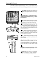
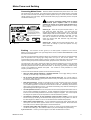


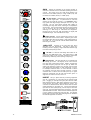

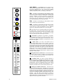


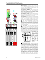


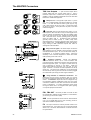
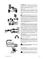
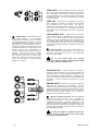
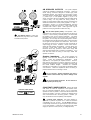

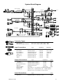

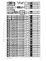

![SIRIUS [ MultiGas Detector ]](http://vs1.manualzilla.com/store/data/006767614_1-4615675783fde9659310b4f985f9cb16-150x150.png)