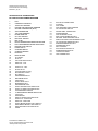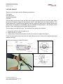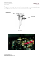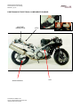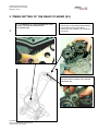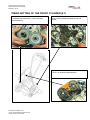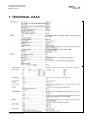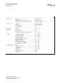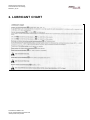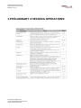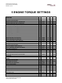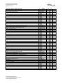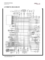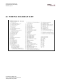
1
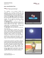
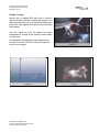
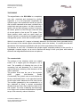
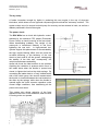
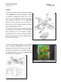
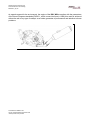
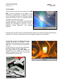
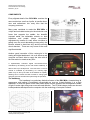
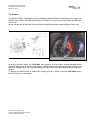
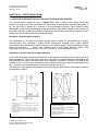
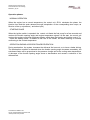
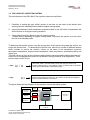
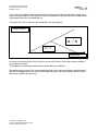
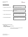
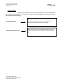
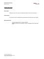
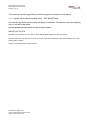
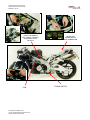
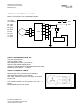
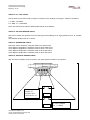
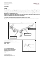
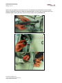
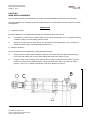
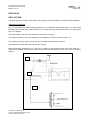
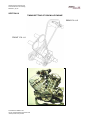
Aprilia Consumer Service Spa
Technical Service and Training
Release 4 july 99
RSV 1000 Technical Training Course
RSV Mille
This material is didactic and
may be changed following the technical
development of the product
Aprilia Consumer Service Spa
Technical Service and Training
Release 4 july 99
RSV 1000 INTRODUCTION
Open your third eye !
The originality of the technical decision the
systematic use of solutions borrowed from the
Racing Department and, above all, the passion and
commitment applied to make every detail exclusive,
form the basis of Aprilia's constructive philosophy. In
particular, the RSV Mille embodies and enhances
the most significant characteristics of this company's
heritage, with its high-level technology, superior
quality of construction and its unique and
unmistakable design.
The RSV Mille brings a substantial change on the
scene of bigh-powered super-sport motorcycles. lts
manoeuvrability and easy riding - typical of two
cylinder bikes - are wedded with the versatility and
high performance of four cylinder bikes.
The RSV Mille is the best production line bike for
use on the track.
A bike that guarantees a pleasant ride, on either
track or road, to satisfy even the most demanding
rider who wants the best as regards easy bandling,
performance, exclusive quality and technology. lt is
decidedly original, exclusive and performing. A
motorcycle in which the love of the racing world is
translated into a wealth of important details. A bike
with a superior performance, occupying a price
range in line with the best of Japanese competitors.
A product which represents, to all effects, a decision
in style for the buyer and, for Aprilia, the first stage of
further development linked with highpowered bikes.
For Aprilia, "the sense of wonder' means breaking
away from set patterns, having the courage to face
new challenges, in this case shaking off a
paradoxically conservatile universe such as the
world of high-powered super-sports motorcycles.
The RSV Mille marks a turning point, opens a new
chapter and becomes the new point of reference
This material is didactic and
may be changed following the technical
development of the product
Aprilia Consumer Service Spa
Technical Service and Training
Release 4 july 99
Design Concept:
Aprilia’s aim in making RSV Mille was to create a
motorcycle with extremely compact dimensions, one
that could cleave the air in an optimumn fashion and
protect the rider against the impact of the wind and
high speeds.
The flow inside the front ait intakes has been
optimazed too, as well as the position of the intakes
on the fairing.
As regards the aereodynamic result obtained, the
achivied CXs value of 0,3010 is the new reference
point for the category.
This material is didactic and
may be changed following the technical
development of the product
Aprilia Consumer Service Spa
Technical Service and Training
Release 4 july 99
THE ENGINE
The engine fitted on the RSV Mille is a completely
new type, conceived and developed by Aprilia's
engineers. It is a 60°V-formation longitudinal two
cylinder engine, with 4 distribution valves per cylinder
and a double camshaft at the head, controlled by a
mixed chain and gear system. lt is fed by electronic
ignition with air input through a system of dynamic
air intakes. lgnition is of the CDI type, where the load
of air and petrol is fired by the TSI system (Twin
Spark lgnition) which uses two spark plugs per
cylinder. lgnition is controlled by the integrate engine
management system, which also controls injection.
While it is true that the 90' V engine is itrinsically balanced (the first order forces generated during
the movement of the internal organs automatically cancel one another), it is equally true that the
dimensione of the engine are penalized by the size of the angle between the cilinders.
The decision to use a 60° V-formation two-cylinder engine responds perfectly to the need for a
lightweight, compact engine, so as not to sacrifica the design of the cycle parts with tecnical
solutions and weight distribution that are not optimum.
The countershafts
The problem of the vibrations which are created
inside a 60 V engine gave the designers a lot of
work. The possibility of offsetting the pins of the
connecting rod was discarded, as it would have
required excessive widening of the dimension of the
motor crankcase.
The solution found was the use of the exclusive
AVDC
patent
(Anti-Vibration
Double
Countershaft).This system uses an anti-vibration by
turning countershaft which, in the opposite direction
to the engine shaft, balances the first order forces.
The moment generated by the countershaft is, in
turn, balanced by fitting a second countershaft
(Smaller than the main one) inside the head of the
rear cylinder. The result of adopting this technology
is an engine with excellent characteristics of power,
torque, with extremeily reduced vibrations.
This material is didactic and
may be changed following the technical
development of the product
Aprilia Consumer Service Spa
Technical Service and Training
Release 4 july 99
The dry sump
A further innovation brought by Aprilia in producing this new engine is the use of dry-sump
lubrication, which allows a more rigid and compact engine block that the "wet-sump" solution. The
system makes use of a second trochoid pump for recovery and an external oil tank, as well as a
radiator positioned in front of the engine.
The power clutch
The RSV Mille has a clutch with hydraulic control,
assisted by the esclusive PPC patent (Pneumatic
Power Clutch) to check bouncing of the rear wheel.
When decelerating suddenly, the weight of the
motorcycle is transferred instantly to the front,
lightening the rear axle. In high-powered twocylinder engines this phenomenon is accentuated by
the high “engine braking" effect; this can cause the
so-called bouncing, or the tendency of the rear
wheel to block and lift off the ground, endangering
the stability of the bike and, consequently, the
vehicle's performance and safety.
Aprilia has found the ideal solution to this problem
exploiting the variations in pressure which occur in
the intake ducts when the throttle is opened and
closed, to lighten the load on the clutch springs. By
connecting the intake ducts to a "lung" situated at the
side of the clutch group, the vacuum created when
the throttle is closed decreases the load exerted on
the disks by the springs, while when the throttle is
opened again the clutch resumes operation under
normal weight conditions, thus transferring all the
power to the rear wheel.
This system also allows reduction of the force
applied on the lever on the handlebar, when the bike
is running at low rev speeds.
This material is didactic and
may be changed following the technical
development of the product
Aprilia Consumer Service Spa
Technical Service and Training
Release 4 july 99
lnjection
The need for suitable control of the powerful engine
of the RSV Mille led the Aprilia designers to adopt
an electronic management system built into the
engine. All the fondamental operating parameters
are
constantly
monitored
by
a
sophisticated
electronic controls unit which, on the basis of the
data received, control operation of both the injection
system and the ignition system.
The injectors are fed by a pump which produces a
constant pressure of 330 Kpa. The throttle bodies
have a diameter of 51 mm. Fresh air is taken in
through ducts which make use of dynamic pressure
when the motor-cycle is moving, sending fresh air
into a large volume airbox.
The entire injection/ignition system is also equipped
with a continuous Selfdiagnosis circuit (both on
starting and when the bike is running); this is able to
indicate any malfunctions of the system directly on
the dashboard, without the aid of complicated and
expensive external equipment.
This material is didactic and
may be changed following the technical
development of the product
Aprilia Consumer Service Spa
Technical Service and Training
Release 4 july 99
The exhaust
The exhaust system of the RSV Mille originates as the reply to four very precise requests: light
weight, aerodynamic line, respect for the environment and for approval standards.
The choice of the "2 in 1 " exhaust proved to be the most appropriate since, while obtaining an
internal volume of over 9 litres, the bulk and weight are lower than those of a l'2 in 2" exhaust.
The exhaust of the RSV Mille made completely of stainless steel, which ensures long life and
lasting good looks.
This material is didactic and
may be changed following the technical
development of the product
Aprilia Consumer Service Spa
Technical Service and Training
Release 4 july 99
As regards respect for the environment, the engine of the RSV Mille complies with the parameters
of the future European standards (EURO 1, which comes into force in 1999); this result is achieved
without the aid of any type of catalyst, as a further guarantee of performance and attention to these
problems.
This material is didactic and
may be changed following the technical
development of the product
Aprilia Consumer Service Spa
Technical Service and Training
Release 4 july 99
CYCLE PARTS
Jewel within the jewel, the cycle parts of the RSV
Mille must be considered to all effects a true
masterpiece of engineering. As beautiful as a work
of art, impeccably but above all efficiently finished,
instinctive and easy to drive, to quarantee optimum
exploitation of all the engine power.
The best engineers in the Aprilia racing department
designed the frame, giving it the most in terms of
planning and knowledge of structures, choice of
materials, weight distribution and dynamic
behaviour.
Particular care was taken with the torsional stiffness (with a record value of 650 Kgm) and bending
resistance of tbc frame, fondamental elements as regards riding precision and safety.
The splendid rear fork with differentiated arms
controls, by means of linka-ges, a multiadjustable shock-absorber with built-in "piggyback" tank. The rear wheel bump position is
135 mm.
At the front the 43 mm Showa "upside-down"
fork allows a bump position of 120 mm.
The cycle parts of the RSV Mille are
supported by a dry weight of only 189 kg,
optimally distributed with 49.2% on the front
axle and 50.8% on the rear axle.
This material is didactic and
may be changed following the technical
development of the product
Aprilia Consumer Service Spa
Technical Service and Training
Release 4 july 99
COMPONENTS
Every slightest detail of the RSV Mille receives the
same meticulous care from Aprilia, to transfer dove,
care and enthusiasm into every bike that the
company produces.
Many parts contribute to make the RSV Mille a
unique and unrivalied rnotorcycle: the aluminium rear
frame that supports the saddle, the beautiful
exposed welds, the adiustable controls on both
handlebar and pedals (where micrometric
adjustment by means of a cam offers a solution to
satisfy even the most demanding motorcyclist), the
Brembo wheels in aluminium alloy and the steering
shock absorber. These are only some of the most
significant details.
Another great innovation of this rnotorcycle is the
analog and digital dashboard. It is to all effects a real
computer on board, able to supply the rider wíth all
the information ho needs at any time.
A sophisticated, exclusive digital chronometer/clock,
controlled by the flashing of the main beam headlamp, is
able to store up to 40 lap times. The "red zone" on the rev
counter is indicated by the flashing of a warning light
(which may be set by the rider at the desired rev speed),
allowing him to choose the best moment to change gear
and gain precious seconds when performing the operation.
The headlamp
The headlamp is a particulary distinctive feature of the RSV Mille, characterizing its
appearance and making it immediately recognizable as soon as it starts flashing. lt is a triple
headlamp, in which the power of the main beam allows a broad, powerful and homogeneous beam
of light, to make night riding even more safe and effective. Two 55 Watt halogen lamps are housed
inside parabolas developed on the computer with the technology of complex surfaces.
This material is didactic and
may be changed following the technical
development of the product
Aprilia Consumer Service Spa
Technical Service and Training
Release 4 july 99
The Brakers:
The Brakers of RSV, developed in close collaboration between Brembo and Aprilia, have calipers at
the front with 4 piston with different diameters (34 and 30 mm) wich act on steel disks with diameter
of 320 mm.
At the rear the bike is fitted with 220 mm disk and caliper with double opposed piston (d=30 mm)
In terms of product quality, the RSV Mille has achieved an even higher internal standard which
already places Aprilia at the top of the market. Quality means not only product quality but also, and
above all, design quality, as is demonstrated by the ISO 9001 certification obtained for ali production
phases.
To assure you that this bike is reliable and a really good buy, Aprilia covers the RSV Mille with a
MotoGo Three-Year Guarantee.
This material is didactic and
may be changed following the technical
development of the product
Aprilia Consumer Service Spa
Technical Service and Training
Release 4 july 99
SECTION 01: INJECTION SYSTEM
1.1 PREFACE: INTRODUCTION ON THE INJECTION-IGNITION SYSTEM
The injection-ignition system is of the " alpha/n, D/J" type, in which motor speed and throttle
position are used as the main parameters for the quantity of aspirated air; knowing the quantity of
air, the fuel level is dosed as a function of the performance required. Other system sensor
atmospheric pressure, air temperature, water temperature allow basic settings to be corrected in
the event of specific conditions. In addition, motor speed and throttle angle allow the optimum spark,
advance to be calculated under any operating condition.
Electronic injection-ignition system.
The application of an electronic control injection-ignition system to eight-stroke-cycle engine,
optimizes their use, providing a higher specific horsepower together with a lower specific
consumption, and reducing the unburt elements in the exhaust gases. These advantages are got
thank to a more exact
air-fuel ratio metering and a good spark advance control. This
equipment consists of three circuits: Fuel circuit, Sucked air circuit and Electric circuit.
Influence of air-fuel ratio and of spark advance.
Air-fuel ratio and spark advance are key factors for the optimum functioning of the engine, and so is
their management. The air-fuel ratio is fhe ratio of air and fuel (weight) supplied to the engine: the
ideal (stechiometric) ratio is achieved when full combustion is ensured. Too much or too little air will
produce a lean or rich mixture, respectively, which affects horse power and fueI consumption (see
fig. 1, as well as the pollutant content in exhaust emissions see fig. 2).
The electronic spark advance management optimises engine performance: peak power, transient,
consumption, pollution.
Fig.2
Fig.1
1) Pollutants/ Polluants/ Umweltbelastende
Abgase /Contaminantes
2) Rich mixture / Melange riche / Reiches
Gemisch / Mezcla rica
3) Lean mixture / Melange pauvre / Armes
Gemisch / Mezcla pobre
4) Ideal ratio / Rapport ideal / Ideales Verhaltnis /
Proporcion ideal
This material is didactic and
may be changed following the technical
development of the product
Aprilia Consumer Service Spa
Technical Service and Training
Release 4 july 99
Operation phases.
NORMAL OPERATION
When the engine has a normal temperature, the control unit –ECU- calculates the phase, the
injection time and the spark advance through interpolation of the corresponding store maps, as
function of the r.p.m/pressure (..and other input)
STARTING PHASE
When the ignition switch is operated, the control unit feeds the fuel pump for a few seconds and
receives the throttle opening angle and engine temperature signals. At the start, the control unit
receives the engine revolutions and phase signals, which allow the injection and ignition control. To
make the starting easier, in addition to the use of the Starter, the base metering is enriched,
conforming to the coolant temperature.
OPERATION DURING ACCELERATION/DECELERATION
During acceleration, the system increases the delivered fuel amount, so to have a better driving.
The acceleration condition is detected when the throttle opening angle increases remarkably; the
enrichment factor will be proportional to the pressure change and to the cooling water temperature.
A decrease of the throttle opening angle shows a deceleration and causes a reduction of the
delivered fuel.
This material is didactic and
may be changed following the technical
development of the product
Aprilia Consumer Service Spa
Technical Service and Training
Release 4 july 99
1.2 RSV 1000 FUEL INJECTION SYSTEM
The main features of the RSV MILLE fuel injection system are as follows:
1.
Possibility of setting the right air/fuel mixture in real time on the basis of the throttle valve
opening, the inlet manifold pressure and the engine running speed.
2.
Improved performance and acceleration response thanks to the SW which compensates the
air/fuel mixture in all engine running conditions.
3.
Clean exhaust emission thanks to the fuel injection system.
Variable timing, depending on engine running states. At present, the system is not set up for
the use of the Lambda probe.
To determine the injection volume, vary the opening time of the injector; the greater the volume, the
longer the injection time. To determine the injection time, there are a number of different sensors
which increase or reduce the injection volume on the basis of the atmospheric pressure,
atmospheric temperature, engine coolant temperature, intake air pressure, accelerator position and
engine rpm.
The basic volume is given by the injection mapping and the sensors send the data to the electronic
control unit to compensate this volume in line with the running conditions of the engine/bike. There
are two maps in the E-Prom:
1. Map
2. Map
α/n
This is the “basic” map that mainly covers the high rpm sector. The
injector opening time, i.e. the injection volume, is determined on the basis
of the rpm and the throttle valve opening angle.
D/J
The D/J map covers the engine low/medium rpm sector. The idling
system is governed by the D/J map. The volume of fuel injected depends
on the manifold pressure and the rpm.
The figure shows the logic diagram for the Injection Volume calculation system.
Paspir.
ECU
INTAKE
PRESSURE
SENSOR
RPM
Pick-up
MAPPE
ANGLE
THROTTLE
‘SENSOR’
COMPENSATION
SENSOR
This material is didactic and
may be changed following the technical
development of the product
INJECTION
VOLUME
Aprilia Consumer Service Spa
Technical Service and Training
Release 4 july 99
The control unit software switches between the DJ map and the alpha/n map on the basis of the
engine running conditions. The injection volume also depends on the other factors provided by the
compensation devices, illustrated later on.
The switch from D/J to alpha/n occurs gradually (See down figure) :
Injection Volume
α /n
D/ J
Throttle angle
As shown in the above figure, the D/J map is almost 100% active in low load running conditions
(e.g. engine in neutral).
The alpha/N curve becomes predominant in power delivery conditions.
Remember that the control unit is connected electrically to the instrument panel, and that there is
also the self-diagnosis function. When in the diagnosis option, the panel displays the fault codes
that act as a guide in the servicing.
This material is didactic and
may be changed following the technical
development of the product
Aprilia Consumer Service Spa
Technical Service and Training
Release 4 july 99
Compensation devices:
Positioned inside the control unit box. Reads the
Patm.
The control unit normally reduces the injection volume
in low atmospheric pressure conditions
1. Atmospheric pressure sensor
2. Engine coolant temperature sensor
This sensor reads the coolant temperature. If the
temperature reading is low, the control unit increases
the injection times
3. Intake air temperature sensor
This sensor reads the temperature of the intake air; if
the temperature is low, the injection time is increased
4. Gear position (idling switch)
This logic sensor verifies whether or not the gearbox is
in the neutral position. The signal also affects the
phasing.
Other significant compensation factors:
-
Battery voltage
Starting compensation (engine warming)
Delta Alpha compensation:
-
This material is didactic and
may be changed following the technical
development of the product
boosts the engine fuel supply during rapid acceleration
cuts off the fuel during deceleration
Aprilia Consumer Service Spa
Technical Service and Training
Release 4 july 99
-
Timing control
The times are controlled by the reading of the position of the crankshaft and
the position of the camshaft. The control unit also detects the starting phase, injecting the fuel into
the cylinders asynchronously.
Crankshaft sensor
Camshaft position sensor
This material is didactic and
may be changed following the technical
development of the product
Reads the position of the crankshaft, discretizing angles of
60°
Sends a voltage to the control unit, like any pick-up.
This signal controls the fuel pump via the ECU.
Reads the position of the camshaft and sends the signal to
the ECU. The sensor reads the position of the front cylinder
only.
Aprilia Consumer Service Spa
Technical Service and Training
Release 4 july 99
Injection stop control
Rpm limiter:
Software control. The control unit stops the injection if the rpm are excessive.
Deceleration:
The injector function is disabled during deceleration with the throttle valve closed.
Side stand switch:
Prevents starting when in running conditions
Switches the bike off immediately if a gear is engaged with the side stand
down
This material is didactic and
may be changed following the technical
development of the product
Aprilia Consumer Service Spa
Technical Service and Training
Release 4 july 99
Safety systems
Kick back Prevention:
At about 300 rpm (if the rpm have been over 800 rpm) the control unit deenergizes the coil signal to prevent a possible kick-back in the pistons when turning the bike off.
Tip over sensor:
If the bike tips over, the tip over sensor stops the injectors’ control signal and
fuel pump. The sensor is a mechanical switch already used on other bikes on the market. Reset
the CPU by switching off the bike to re-enable the normal functioning of the control unit.
Side stand and clutch switches (possible conditions):
This material is didactic and
may be changed following the technical
development of the product
Aprilia Consumer Service Spa
Technical Service and Training
Release 4 july 99
1.3 SELF-DIAGNOSTICS FUNCTION:
The self-diagnostics function is part of the ECU software and is a valid aid to trouble-shooting in the
electronic injection system.
HOW THE FUNCTION WORKS:
With the control unit and dashboard connected and the key “on”, the multi-function LCD displays
the message “EFI” instead of the temperature reading for about 3 seconds
If the EFI message disappears after 3 seconds and TEMPERATURE appears (°C, °F or COLD),
this means that the injection control unit has found no static errors in the injection components. To
check the crankshaft and camshaft sensors, make a starting attempt lasting > 4 sec.
If EFI DOES NOT appear, this means there is no connection between the display and the control
unit (DIAG lead disconnected à check wiring)
If the EFI message persists, this means that the control unit has found a fault in the
sensors/components. Go into the Dealer Mode.
The diagnostics function is divided up as follows:
-
USER MODE: If there is a fault, the user will see the “EFI” message remaining on the display
after starting. This is the only sensors/coils fault message that can be seen by the user
-
DEALER MODE: Using connector 68, the mechanic will be able to read the corresponding fault
code on the LCD
How to access DEALER MODE:
1- Ground the control unit diagnostics terminal via connector 68 (see diagram). The message
DIAG will appear on the display
This material is didactic and
may be changed following the technical
development of the product
Aprilia Consumer Service Spa
Technical Service and Training
Release 4 july 99
2-If everything is functioning perfectly, the following figures may appear on the display:
-1, 0, 1 (throttle valve opening standard values – SEE CO SETTING)
3- If there are any faults, the fault codes will appear in sequence. The sequence will keep repeating
until you exit the Dealer Mode.
!!!! AFTER REPAIRING THE FAULT SWITCH THE BIKE ON AGAIN TO CHECK
IMPORTANT NOTES:
Whether or not the bike can be turned on in the Dealer Mode depends on the type of fault.
The ECU must be on for the fault codes to be saved; if the bike is switched off (STOP Condition) the codes
memory will be erased
There is no SW/HW control on the injectors
This material is didactic and
may be changed following the technical
development of the product
Aprilia Consumer Service Spa
Technical Service and Training
Release 4 july 99
1.4 FAULTS TABLE
FAULT CODE
11
12
COMPONENT INVOLVED
CAMSHAFT SENSOR
CRANKSHAFT SENSOR
CAUSE
Sensor not connected, faulty
wiring, sensor broken
START ENGINE
Sensor not connected, faulty
wiring, sensor broken
START ENGINE
(t>4 sec)
(t>4 sec)
13
INTAKE PRESSURE SENSOR
Sensor not connected, faulty
wiring, sensor broken
ENGINE RUNNING OR
ENGINE STOPPED
14
INTAKE/ATMOSPHERIC PRESSURE
SENSOR
Increased differences
between sensor signals
ENGINE RUNNING OR
ENGINE STOPPED
15
THROTTLE SENSOR
Sensor not connected, faulty
wiring, sensor broken
ENGINE RUNNING OR
ENGINE STOPPED
21
COOLANT TEMPERATURE SENSOR
Sensor not connected, faulty
wiring, sensor broken
ENGINE RUNNING OR
ENGINE STOPPED
22
AIR TEMPERATURE SENSOR
Sensor not connected, faulty
wiring, sensor broken
ENGINE RUNNING OR
ENGINE STOPPED
23
ATMOSPHERIC PRESSURE SENSOR
Sensor – inside control unit ENGINE RUNNING OR
ENGINE STOPPED
– defective
33
COIL 1 CYLINDER1
Coil not connected, faulty wiring,
sensor broken
ENGINE RUNNING
34
COIL 2 CYLINDER 1
Coil not connected, faulty wiring,
sensor broken
ENGINE RUNNING
35
COIL 1 CYLINDER 2
Coil not connected, faulty wiring,
sensor broken
ENGINE RUNNING
36
COIL 2 CYLINDER 2
Coil not connected, faulty wiring,
sensor broken
ENGINE RUNNING
41
TIP OVER SENSOR
NOT CONNECTED
ENGINE RUNNING OR
ENGINE STOPPED
DEFECTIVE
NO START
CONDITIONS AT START
-
Tip over conditions
-
Safety logic not
satisfied
-
Two defective coils
on same cylinder
WHAT TO DO WHEN A FAULT CODE APPEARS:
1.
2.
3.
NOTES
CHECK COMPONENT WITH TESTER
CHECK CONTACTS (SENSOR/WIRING– WIRING/CONTROL UNIT)
CHECK WIRING
This material is didactic and
may be changed following the technical
development of the product
See table
Aprilia Consumer Service Spa
Technical Service and Training
Release 4 july 99
TROUBLE SHOOTING:
WHAT TO DO IF THE ENGINE DOESN’T START AND NO FAULT IS SHOWN ON THE SELF-DIAGNOSTICS
SYSTEM
-
Check the fuel pump
Check the injectors
Check that the anti-theft system connector is connected
Check the key switch
Check the STOP-RUN control
Check the 30 Amp fuses and 15 Amp fuses B and E
Check the engine stop relay
Check the battery
Check the safety system logic (diode box, switches)
This material is didactic and
may be changed following the technical
development of the product
Aprilia Consumer Service Spa
Technical Service and Training
Release 4 july 99
START AND RUN POSSIBILITY:
If a fault is detected, the control unit may:
-
stop the bike
allow running but not starting
allow running and starting
as described in the table:
FAILURE
START POSSIBILITY
RUN POSSIBILITY
CAMSHAFT SENSOR
NOT POSSIBLE
POSSIBLE
CRANKSHAFT SENSOR
NOT POSSIBLE
NOT POSSIBLE
MANIFOLD PRESSURE SENSOR OR
PRESSURE SENSOR SIGNAL
POSSIBLE
POSSIBLE
THROTTLE POSITION SENSOR
POSSIBLE
POSSIBLE
COOLANT TEMPERATURE SENSOR
POSSIBLE
POSSIBLE
INTAKE AIR TEMPERATURE SENSOR
POSSIBLE
POSSIBLE
ATMOSPHERIC PRESSURE SENSOR
POSSIBLE
POSSIBLE
IGF11 OR IGF12
POSSIBLE
POSSIBLE
IGF11 AND IGF12
POSSIBLE (ONE CYLINDER ONLY)
POSSIBLE (ONE CYLINDER ONLY)
IGF21 OR IGF22
POSSIBLE
POSSIBLE
IGF21 AND IGF22
POSSIBLE (ONE CYLINDER ONLY)
POSSIBLE (ONE CYLINDER ONLY)
IGNITER:
This material is didactic and
may be changed following the technical
development of the product
Aprilia Consumer Service Spa
Technical Service and Training
Release 4 july 99
OPERATION - DASHBOARD KEYS
[A] [B] [R] [C] [D]
1.
SEGMENTS OPERATION CHECK:
Press keys [A] and [B] and turn the key from OFF to ON: all segments stay lit as long as [A] and [B] are
pressed.
2.
KM/H, MPH
Press key [A] for 5 seconds =:> numbers and km/h (mph) flash
Press key [B] to change unit of measurement
Confirm with [A] pressed for about 5 seconds.
3. INSTANTANEOUS, MAXIMUM AVERAGE SPEED (only with instantaneous S = 0)
Instantaneous speed => press key [B] for about 1 second
Maximum speed => press key [B] for about 1 second
Average speed => press key [B] for about 1 second
a) 1st partial reset:
instantaneous speed on display => press key [R] for about 3 seconds => 1st partial = 0
b)
maximum speed reset:
maxS and 1st partial on display => press key [R] for about 1 second => maxS = 0.
c)
average speed and 2nd partial reset:
avgS and 2nd partial on display => press key [R] for about 1 second => avgS = 0,
2nd partial = 0
With the display showing maxS or avgS and insS becomes > 0 the display shows insS.
5.
EXCESS RPM WARNING LIGHT (ONLY WITH ENGINE OFF)
-Press [C] for t < 1 second => set value displayed for seconds
-Key pressed for more than 1 second - pointer moves at 1000 RPM/step as long as [C]
is pressed
-If the key is released and then pressed again within 3 seconds for less than 1 second the setting
increases by 100 RPM/pulse.
-If key [C] is not pressed for more than 3 seconds the setting is stored (confirmed by lighting of
indicator light).
This material is didactic and
may be changed following the technical
development of the product
Aprilia Consumer Service Spa
Technical Service and Training
Release 4 july 99
6. MULTIFUNCTION
Coolant temperature and clock => [D] =>
Battery voltage => [D] =>
Set hours (Press LAP) =>
Set minutes (Press LAP) =>
Set °C/°F (Press LAP) => go back to
b) Stop watch
Press and hold [LAP] and then (within 0.7 seconds) press key [D] to start the stop watch.
b.
b.2)
1) Press [LAP] ==> stop watch starts (the [LAP] key is not enabled for 10 sec.)
Starting from timing =:> press [B] => display shows first acquired time => press [LAP] to
re-display times in sequence
-Press [B] to go back to timing
-Press [A] + [LAP] for 2 seconds to zero memories
b.3) To exit timing press [D] and then [LAP] (temperature and clock will appear on display).
6.
Switch off SERVICE => press [LAP] and [R] for 5 seconds.
This material is didactic and
may be changed following the technical
development of the product
Aprilia Consumer Service Spa
Technical Service and Training
Release 4 july 99
SECTION 2: IGNITION SYSTEM
The ignition system is controlled by the control unit. The system is a normal one, known as a
digital transistorised ignition system, which sets the correct timing on the basis of the engine
rpm and throttle position. It is made up of the crankshaft sensor (pick up coil), control unit, two
ignition coils and spark plugs.
POSITIVO
MAPPING
ROM
WAVE
FORM
ARRANGE
CIRCUIT
THROTTLE
POSITION
VIBRATOR
CPU
TEMP.
SENSOR
GEAR
SWITCH
1. The ignition coil power supply is governed by the side stand safety circuit and by the gear
position.
2. The timing is constantly controlled by the throttle position and the rpm
The devices described below affect the timing in the stopping or starting of the ignition
system.
Crankshaft sensor:
The engine pick up coil produces a signal when it meets the projecting part of the
magneto flywheel.
The wave generated is sent to the control unit which calculates the engine rpm; this
signal determines the timing.
Throttle position sensor:
This sensor, mounted on the throttle body, has a variable resistance which changes the
opening value of the throttle. On the basis of this signal, the control unit sets the timing in
response to the engine rpm.
The timing mapping is made up of two factors: the throttle position and the engine rpm.
The ignition is inductive and not the capacitive discharge type. ! NEVER SHORT CIRCUIT TO
GROUND THE L.T. LEADS TO THE COILS
This material is didactic and
may be changed following the technical
development of the product
Aprilia Consumer Service Spa
Technical Service and Training
Release 4 july 99
CONTROL STRATEGY
In the ignition phase, the control unit reads the starting, as shown in the separate figure.
BATTERIA
The ignition phase starts in this way
(asynchronous/synchronous phase):
1. The control unit reads:
-
coolant temperature
throttle angle
engine rpm
Patm.
Battery voltage
RELE’
AVVIA
M
ECU
These values determine the ignition time when the engine is started.
The mapping, based on the timing, is based on
BTDC (Before top dead centre), and depends on
the throttle opening angle and the engine rpm.
rpm
Throttle
angle
This material is didactic and
may be changed following the technical
development of the product
Aprilia Consumer Service Spa
Technical Service and Training
Release 4 july 99
2. Cylinder recognition
The camshaft and pick up sensors send signals that are clipped by the ECU.
The camshaft sensor sends one signal for each cycle
IGNITION/EXPANSION-EXHAUST), corresponding to an angle of 720°
(INT-COMPRESS-
The camshaft sensor sends 12 signals for each rotation of the crankshaft, i.e. one signal every
60°.
The first camshaft pulse enables the resetting of an internal counter which starts the
synchronous ignition phase and cylinder recognition.
The following phase is known as asynchronous as both the injectors inject fuel into the ducts.
The ignition phase is illustrated in the diagram below.
OFF
spark
spark
spark
This material is didactic and
may be changed following the technical
development of the product
Aprilia Consumer Service Spa
Technical Service and Training
Release 4 july 99
IGNITION:
The HT coils control is linked to the pick up signal after the recognition of the cylinders (see
figure above).
At low rpm (< 540) the ignition is set by the clipped signal of the pick up. The CPU gives
consensus to the ignition only. These are “fixed spark timing” and “ fixed dwell timing”
conditions.
At medium rpm levels, the spark dwell timing is fixed but the spark advance timing varies.
At high rpm (>3500) the ignition timing is calculated by the ECU and suitably compensated
(calculated spark and dwell timing conditions).
IDLING:
Applies to the 200 to 1200 rpm range. A hysterisis cycle is followed (as shown in the figure);
the spark and advance times are fixed.
540
200
This material is didactic and
may be changed following the technical
development of the product
1200
Aprilia Consumer Service Spa
Technical Service and Training
Release 4 july 99
SECTION 3 : DESCRIPTION OF ELECTRONIC INJECTION SYSTEM
The RSV1000 electronic injection system is made up of the following components:
1. Electronic control unit
2. Sensors (shaft position, temperature, pressure...)
3. Actuators
4. Ignition coils
5. Fuel pump
The ECU also contains the static-inductive ignition circuit.
This material is didactic and
may be changed following the technical
development of the product
Aprilia Consumer Service Spa
Technical Service and Training
Release 4 july 99
3.1 THE E.C.U.: ELECTRONIC CONTROL UNIT
The injection system and ignition system operation are controlled by the Nippodenso ECU, code no.
265470 (not final!!!).
The control unit is connected to the rest of the bike’s electrical system by two ‘fast’ connectors. As
well as being fed with power and receiving signals from the sensors through these connectors, the
control unit also controls the injectors and l.t. ignition coils and dialogues with the panel and, in
addition, checks that the correct torque is transmitted to the wheels. The figure below gives a basic
outline of these connections:
The ECU is governed by an 8 bit/8Mhz CPU which performs the logic and control functions. The
calculation tables and algorithms are resident in the E-PROM.
C.P.U.
Centralina ECU
Centralina
ECU: C.S.
CONNETTORI ECU
This material is didactic and
may be changed following the technical
development of the product
E-PROM SU ZOCCOLO
Aprilia Consumer Service Spa
Technical Service and Training
Release 4 july 99
In addition, the following systems/components are inside the control unit:
-
coils/injectors control power circuit
Atmospheric pressure sensor
CO regulation trimmer
Trimmer regolazione CO
CO ECU SETTING
This material is didactic and
may be changed following the technical
development of the product
Aprilia Consumer Service Spa
Technical Service and Training
Release 4 july 99
ECU ELECTRONIC WIRING DIAGRAM:
This material is didactic and
may be changed following the technical
development of the product
Aprilia Consumer Service Spa
Technical Service and Training
Release 4 july 99
ONNECTORS:
The control unit is connected to the electrical circuit by plug-in connectors that plug into the ECU
printed circuit.
The connectors connect the control unit to the sensors and actuators (injectors, coils) via the
wiring.
Also, most of the connected components can be tested via the connectors, using any type of good
quality ohmic tester.
As detailed in the wiring diagram, the connectors refer to the specific components shown in the
figure:
26 WAY CONNECTOR
16 WAY CONNECTOR
IDENTIFICAZIONE
TERMINALI ECU
This material is didactic and
may be changed following the technical
development of the product
Aprilia Consumer Service Spa
Technical Service and Training
Release 4 july 99
SECTION 4 POSITIONING OF SENSORS AND INJECTORS:
The position of each of the sensors is shown in the figure:
This material is didactic and
may be changed following the technical
development of the product
Aprilia Consumer Service Spa
Technical Service and Training
Release 4 july 99
CAMSHAFT SENSOR:
The cam sensor is an inductive sensor installed in the front cylinder head and is identical to the
pick-up. This sensor is of fundamental importance and allows the ECU to recognise the exact
sequence of each single cylinder, resetting the internal count to zero during the asynchronous
ignition phase. The ohmic resistance of the sensor, measured at a temperature of 20 degrees, is
about 240 Ohms. This resistance can be measured either directly on the sensor wiring or at the
ECU connectors, connecting a tester between the terminals, as shown.
SW –ECU DIAGNOSIS
OHMIC DIAGNOSIS
MEASURED BETWEEN
WIRES
This material is didactic and
may be changed following the technical
development of the product
EXISTENT
AVERAGE VALUE 240 Ohms
2-10 (PURPLE/BLACK and
GREY/BLACK)
RIGHT-HAND CONNECTOR
Aprilia Consumer Service Spa
Technical Service and Training
Release 4 july 99
THROTTLE SENSOR:
The throttle sensor, a highly reliable potentiometer, is a 4-pin resistive sensor. The sensor sends a
voltage signal, proportional to the opening angle of the throttle valve, to the control unit. The sensor
is positioned in the throttle assembly, as shown in the figure.
The figure shows the sensor connections and the sensor resistance curve/angle.
SW –ECU DIAGNOSIS
OHMIC DIAGNOSIS
MEASURED BETWEEN
WIRES
This material is didactic and
may be changed following the technical
development of the product
EXISTENT
AVERAGE VALUE 3500 OHM
(ALPHA=0)
15 LH CONNECTORS: BLUE/RED
3 RH CONNECTORS: BROWN/WHITE
4 RH CONNS.: BROWN/YELLOW
Aprilia Consumer Service Spa
Technical Service and Training
Release 4 july 99
CRANKSHAFT SENSOR: PICK - UP
An inductive sensor, already familiar from other models, positioned inside the magneto flywheel.
Sends a voltage pulse to the control unit for every 60° of rotation and is of fundamental importance,
together with the camshaft pulse, in allowing the ECU to set the injection and ignition times.
The bike will stop if this sensor breaks (see START and RUN POSSIBILITY TABLE)
SW –ECU DIAGNOSIS
OHMIC DIAGNOSIS
MEASURED BETWEEN
WIRES
This material is didactic and
may be changed following the technical
development of the product
EXISTENT
AVERAGE VALUE 240 Ohms
9-1 (WHITE/YELLOW AND BLUE/YELLOW)
RIGHT-HAND CONNECTOR
Aprilia Consumer Service Spa
Technical Service and Training
Release 4 july 99
TIP OVER SENSOR:
This is a mechanical ring-switch which stays in contact with the plastic section as long as the bike
is in a normal position. When the bike leans, the ring moves and, if the angle is greater than 44
degrees, it activates the switch terminals.
A monitoring resistor is connected in parallel to the switch, for the control unit to check the
connection to the component.
This new sensor is fitted on the battery box and reads the angle of the bike.
If the “lean” angle is greater than 44°, the switch is activated and - after a period of time set in the
control unit SW - the injection, fuel feed and ignition systems are disabled.
SW –ECU DIAGNOSIS
OHMIC DIAGNOSIS
MEASURED BETWEEN
WIRES
This material is didactic and
may be changed following the technical
development of the product
EXISTENT
OPEN CIRCUIT
7-14 (GROUND and RED)
RIGHT-HAND CONNECTOR
Aprilia Consumer Service Spa
Technical Service and Training
Release 4 july 99
ENGINE COOLANT TEMPERATURE SENSOR:
This temperature sensor has a variable resistance
which decreases with the increase in temperature.
The ECU provides the sensor with a +5 Volt signal
and measures the corresponding current, thus
calculating the temperature, based on the
characteristics of the sensor.
Each of the cylinders has one of these sensors,
although only one of them is connected to the ECU
(the other is connected to the control panel).
SW –ECU DIAGNOSIS
OHMIC DIAGNOSIS
MEASURED BETWEEN WIRES
EXISTENT
AVERAGE VALUE(20C°) 2700 OHMS (DELTA CAN
BE 300 OHM)
15 LH CONNECTORS :BLUE RED
6 RH CONNECTORS: RED/BLACK
AIR TEMPERATURE SENSOR:
This temperature sensor has a variable resistance
which decreases with the increase in temperature.
The ECU provides the sensor with a +5 Volt signal
and measures the corresponding current, thus
calculating the temperature, based on the
characteristics of the sensor.
SW –ECU DIAGNOSIS
OHMIC DIAGNOSIS
MEASURED BETWEEN
WIRES
This material is didactic and
may be changed following the technical
development of the product
EXISTENT
AVERAGE VALUE (20C°) 2700
OHMS (DELTA CAN BE 300 OHM)
15 LH CONNECTORS :BLUE RED
13 RH CONNECTORS: RED/GREEN
Aprilia Consumer Service Spa
Technical Service and Training
Release 4 july 99
MANIFOLD PRESSURE SENSOR:
This sensor reads the pressure in the air cleaner box and provides a linear voltage in the range of 1 to 4.2 Volts
to the control unit. It must be supplied with a continuous voltage of +5 Volts (provided by the control unit). The
operating pressure ranges from13.3 to 120 Kpa (abs).
The characteristic of the sensor is:
Vo=Vcc*(0.006*Pi+0.12) [Volts]
The figure shows the instrumental test phase for the sensor in question:
+ 5 Volt DC
Vc
c
tester
Vo
GND
This material is didactic and
may be changed following the technical
development of the product
Pressure Range
14 to 120 KPa
Aprilia Consumer Service Spa
Technical Service and Training
Release 4 july 99
INJECTORS:
Each cylinder has an injector. The location in the throttle assembly is shown in the figure:
The injector used is made up of the following components:
1.
2.
3.
4.
5.
Mesh filter
Compression spring
Valve shaft
Injector coil
Injector jet
SIGNAL
CONTROL
CIRCUIT
TRANSISTOR
FUEL
+ VCC BATTERY
This material is didactic and
may be changed following the technical
development of the product
Aprilia Consumer Service Spa
Technical Service and Training
Release 4 july 99
OTHER RELEVANT ELECTRICAL COMPONENTS:
STARTER MOTOR:
The characteristic operating curves are shown below:
This material is didactic and
may be changed following the technical
development of the product
Aprilia Consumer Service Spa
Technical Service and Training
Release 4 july 99
DIODE MODULE:
The figure shows the electrical wiring in the module. The continuity of the diodes can be checked with a tester
or with a 4.5 - 12 Volt battery with an arbitrary load of max. 2 Watts.
Remember that the diode conducts the current one way only, as indicated by the arrow representing the
component in the diagram.
This material is didactic and
may be changed following the technical
development of the product
Aprilia Consumer Service Spa
Technical Service and Training
Release 4 july 99
VOLTAGE REGULATOR:
The voltage regulator is situated at the rear of the bike on the right, in contact with the bodywork.
NEGATIVO
POSITIVO
This material is didactic and
may be changed following the technical
development of the product
Aprilia Consumer Service Spa
Technical Service and Training
Release 4 july 99
TRASLATION OF LEGENDA FOR
RS 1000 ELECTRIC WIRING DIAGRAM
1
2
3
4
5
6
7
8
9
10
11
12
13
14
15
16
17
18
19
ECU
CAMSHAFT SENSOR
THROTTLE SENSOR
INTAKE AIR PRESSURE SENSOR
WATER THERMISTOR (ECU)
AIR THERMISTOR
TIP OVER SENSOR
DIODE MODULE
CLUTCH SWITCH
NEUTRAL SWITCH
RELAY R1
RIGHT MAIN/DIPPED BEAM SELECTOR
LEFT MAIN/DIPPED BEAM SELECTOR
ENGINE STOP RELAY
PUMP RELAY
STARTER RELAY
STARTER MOTOR
BATTERY
MAIN FUSES
20
21
22
23
24
25
26
27
28
29
30
31
32
33
34
35
36
37
38
39
40
41
42
43
44
45
46
47
48
49
FLYWHEEL
PICK UP
VOLTAGE REGULATOR
REAR CYL. COIL
REAR CYL. COIL
FRONT CYL. COIL
FRONT CYL. COIL
SPARK PLUG
VACUUM SWITCH (ISC)
SECONDARY FUSES
KEY SWITCH
DIPPED BEAM RELAY
MAIN BEAM RELAY
FANS RELAY
FRONT SIDE LIGHT
MAIN BEAM LIGHT
DIPPED BEAM LIGHT
FRONT RH DIRECTION INDICATOR
FRONT LH DIRECTION INDICATOR
THERMOMETER SWITCH
LH MAIN/DIPPED BEAM SELECTOR
TAILLIGHT
DASHBOARD
REAR LH DIRECTION INDICATOR
FRONT CYL. INJECTOR
REAR CYL. INJECTOR
FRONT BRAKE BRAKE LIGHT SWITCH
REAR BRAKE BRAKE LIGHT SWITCH
REAR RH DIRECTION INDICATOR
HORN
This material is didactic and
may be changed following the technical
development of the product
50
51
52
53
54
55
56
57
58
59
60
61
62
63
64
65
66
67
68
MULTIPLE CONNECTORS
FLASHER
FUEL PUMP
FUEL WARNING LIGHT SENSOR
OIL PRESSURE SWITCH
WATER TEMP. THERMISTOR
SPEED SENSOR
FUEL WARNING LIGHT
SIDE STAND WARNING LIGHT
NEUTRAL GEAR WARNING LIGHT
DIRECTION INDICATOR WARNING LIGHT
OIL PRESSURE WARNING LIGHT
MAIN BEAM WARNING LIGHT
DASHBOARD LIGHT
REV COUNTER
MULTIFUNCTION DISPLAY
SPEEDOMETER DISPLAY
LIGHTS/LAP DIODE
TEST CONNECTOR
Aprilia Consumer Service Spa
Technical Service and Training
Release 4 july 99
3.2 FUEL CIRCUIT
The fuel circuit is made up of the following components:
1 fuel pump
2 fuel feed pipe
3 pressure regulator
4 injector.
The fuel pump is immersed in the fuel tank and pumps the pressurised fuel to the feed pipe, where
the pressure regulator keeps the fuel pressure about 3 bars higher than the intake pressure. The
excess pressure is “vented” by the regulator and the excess fuel goes back to the tank through the
return hose. The regulator is controlled by the inlet manifold average pressure. The pressure on the
injector is thus compensated by the intake ducts pressure.
The fuel pump is the WESCO type. The functions of the pump are as follows:
1. Pressurise the fuel in the fuel feed circuit
2. Relief valve for p> 5-6 atm
3. Check valve to maintain the pressure in the circuit when the engine is turned off
There is a mesh filter at the pump inlet port; after filtering, the fuel is sent to the impeller-type pump
chamber (see fig.).
The fuel pump capacity is about 60 litres/h.
This material is didactic and
may be changed following the technical
development of the product
Aprilia Consumer Service Spa
Technical Service and Training
Release 4 july 99
The regulator - shown in the figure - has the following components: a vacuum-operated diaphragm
and spring, and a steel ball valve with the valve seat mounted on the spring.
DEPRESSURE
FUEL TANK
FUEL TANK
This material is didactic and
may be changed following the technical
development of the product
Aprilia Consumer Service Spa
Technical Service and Training
Release 4 july 99
POSITIONING OF ELECTRICAL COMPONENTS ON BIKE:
VOLTAGE
REGULATOR
SPEED SENSOR
This material is didactic and
may be changed following the technical
development of the product
ECU
COIL
Aprilia Consumer Service Spa
Technical Service and Training
Release 4 july 99
THROTTLE SENSOR
ABS. PRESS. SENSOR
Temperature sensor
Oil switch
COIL
This material is didactic and
may be changed following the technical
development of the product
DIODE UNIT
POWER RELAY
DIAG CONNECTOR
STAND SWITCH
Aprilia Consumer Service Spa
Technical Service and Training
Release 4 july 99
SECTION 5: ELECTRICAL CHECKS
Refer to the key below when consulting this chapter:
Ar= orange
Az= light blue
B= blue
Bi= white
G= yellow
Gr= grey
M= brown
N= black
R= red
R= pink
V= green
Vi= purple
V/Az
Bi/R
R/N
Bi/R
30 A
G
30 A
R/B
G
G
V
V REG
G
V
+
CHECK 1. RECHARGE VOLTAGE TEST
Check the electrolyte level
Check the battery voltage
Start the engine and take it up to 4000 rpm
Switch the light switch to dipped beam
test the DC voltage between the battery terminals with a tester
STANDARD VOLTAGE: 13 – 15 VOLTS
CHECK 2. ALTERNATOR CHECK
Disconnect the brown connector from the regulator
Start the engine and take it up to 4000 rpm
The voltage, measured as shown in the figure, must be not
less 60 Volts
The standard resistance of the generator coil is 0.1 – 1
Ohms.
Between cables and ground: infinite
This material is didactic and
may be changed following the technical
development of the product
-
Aprilia Consumer Service Spa
Technical Service and Training
Release 4 july 99
CHECK 3: H.T. COIL CHECK:
Use the tester in the Ohms scale to check the continuity of the windings. The approx. values are as follows:
L.T. SIDE: 3-6 OHMS
H.T. SIDE: 12 – 15 KOHMS
Note: This method is NOT able to detect partial failures in the isolation
CHECK 4: TIP OVER SENSOR CHECK:
Remove the sensor plus grommet from its housing and tilt it sideways at an angle greater than 45° to simulate
a fall.
The standard reading must be 0-1 Ohms.
CHECK 5: THERMISTOR CHECK:
Check the sensor resistance, using the tester in the Ohms scale.
At 20 degrees centigrade the resistance must be about 2450 Ohms
At 40 degrees centigrade the resistance must be about 1114 Ohms
At 60 degrees centigrade the resistance must be about 584 Ohms
At 90 degrees centigrade the resistance must be about 245 Ohms
CHECK 6: THROTTLE SENSOR CHECK:
With the sensor installed, check as shown in the figure (with the throttle in any position)
Variare angolo
farfalla: La
resistenza deve
variare da 0 a "A”
A:Valore standard:
2,9 – 5,3 Kohm
This material is didactic and
may be changed following the technical
development of the product
Aprilia Consumer Service Spa
Technical Service and Training
Release 4 july 99
Fitting the throttle sensor:
(Please see section 9 for CO regulation)
With the engine off, turn the ignition key to ON.
When positioned in the throttle body, enable the control unit diagnostics function.
If there are no errors (i.e. sensors all OK) one of three possible numbers will appear:
+1: initial angle reading too high
0: throttle position OK
-1: initial angle reading too low
Turn the sensor until the 0 appears.
Fix the sensor in position.
Next, proceed with making the fine air setting on the injectors to balance the idling rate
This material is didactic and
may be changed following the technical
development of the product
Aprilia Consumer Service Spa
Technical Service and Training
Release 4 july 99
CHECK 7: PRESSURE SENSOR CHECK:
The readings below, taken one by
Ohmmeter between 1-3
Ohmmeter between1-2
one, must give a value of 15 kOhms
CHECK 8: DIODE MODULE CHECK:
Disconnect the connector from the diode module and apply the circuit described below
terminals, as listed in the table:
Lampadina: 12V/2Watt
+
NEG
The switching-on order must be as shown in the table:
- \+ 1
1
X
2
3
4
5
This material is didactic and
may be changed following the technical
development of the product
2
On
X
3
On
4
On
5
On
X
X
On
X
to the different
Aprilia Consumer Service Spa
Technical Service and Training
Release 4 july 99
This material is didactic and
may be changed following the technical
development of the product
Aprilia Consumer Service Spa
Technical Service and Training
Release 4 july 99
CHECK 9: FUEL PUMP CHECK:
Lift the fuel tank
Disconnect the pump assembly 3 way connector
Feed the green (+) and blue (-) wires coming from the side of the pump assembly with 12 Vdc.
Ensure that the pump works by giving a buzz and checking that the fuel comes out of the throttle assembly
(disconnect the tube).
FUEL PUMP WIRING DIAGRAM
Ar/V
BATT/KEY
RELE’ ARRESTO
MOTORE
CONNETTORE
ANTIFURTO
V/Gr
Az/Gr
RELE’ POMPA
BENZINA
V/N
Vi/Gr
ECU
Ar/Gr
P
This material is didactic and
may be changed following the technical
development of the product
FUEL PUMP
Aprilia Consumer Service Spa
Technical Service and Training
Release 4 july 99
LIGHT WIRING DIAGRAM
PASSING/LAP
CLAXON
LIGHTS
LIGHTS P
LIGHTS H
H - Lo
H – HI
TURN R
TURN L
32
67
A
31
D
29
FANALE POST.
FANALE ANTERIORE
36
34
35
35
72 72 63
DISPLAY CRONOMETRO
LEGENDA:
29=
31=
32=
34=
35=
36=
37=
63=
67=
D=
SECONDARY FUSES
MAIN BEAM LIGHTS RELAY
DIPPED BEAM LIGHTS RELAY
FRONT SIDE LIGHTS
MAIN BEAM LIGHTS
DIPPED BEAM LIGHTS
TAILLIGHT
DASHBOARD LIGHTS
PASSING/LAP DIODE
15 AMP FUSE
This material is didactic and
may be changed following the technical
development of the product
Aprilia Consumer Service Spa
Technical Service and Training
Release 4 july 99
CHECK 10: WIRING AND COMPONENTS CHECK
The main electrical components’ connections to the ECU are shown in the outline wiring diagram in
fig.:
68: TEST CONNECTOR
65
19 LEFT
17 LEFT
2 RIGHT
10 RIGHT
CAMSHAFT
SENSOR
2
14 LEFT
15 LEFT
3 RIGHT
4 RIGHT
THROTTLE
SENSOR
3
64
66
INTAKE
PRESSURE
SENSOR
4
5 RIGHT
SPEED SENSOR
TERMISTOR
H20
5
6 RIGHT
RELE’
R1 11
RELE’
FUEL PUMP
22 LEFT
16 LEFT
AIR
TERMISTOR
SENSORE
CADUTA
13 RIGHT
7 RIGHT
5 LEFT
HT COIL
23
1 LEFT
12 LEFT
20 LEFT
21 LEFT
HT COIL
25
8
DIODES
UNIT
25 LEFT
HT COIL 26
11 LEFT
26 LEFT
10 LEFT
8 RIGHT
23 LEFT
9 RIGHT
REAR
INIETTOR
2 LEFT
16 LEFT
CO
This material is didactic and
may be changed following the technical
development of the product
28
21
PICK UP
1 RIGHT
13 LEFT
FRONT
INIETTOR
VACUUM
SWITCH
1LEFT
9 RIGHT
HT COIL
24
45
45
7
15
ECU
44
44
6
Aprilia Consumer Service Spa
Technical Service and Training
Release 4 july 99
In more detail, the terminals refer to the components shown in the table; the standard ohmic values are also
given:
ECU
CONNECTOR
DESCRIPTION OF
NUM.
STANDARD
WIRE COLOUR
TERMINALS
COMPONENT
VALUE
(L=LEFT, R=RIGHT)
CAMSHAFT SENSOR
THROTTLE VALVE
SENSOR
2
3
2
R
10
R
15
L
3
R
4
R
190-300
OHM
PURPLE/BLACK
2,87 – 3,4
KOHM
BLUE/RED
AT 20 °C
BROWN/YELLOW
GREY/BLACK
BROWN/WHITE
(3-4 VARIABLE
RESISTANCE
FUNCTION OF
ANGLE)
INTAKE PRESSURE
SENSOR.
4
15
L
3
R
10 - 15 KOHM
BROWN/WHITE
SEE
H20 THERMISTOR
AIR THERMISTOR
TIP OVER SENSOR
PICK UP
5
6
7
21
GND
FRONT INJECTOR
REAR INJECTOR
HT COIL
HT COIL
HT COIL
HT COIL
5
R
15
L
6
COMP CHECK
45
23
24
25
26
BLUE/RED
R
15
L
IDEM
BLUE/RED
13
R
7
R
14
R
9
R
1
R
RED/BLACK
RED/GREEN
OPEN
GROUND
RED
190-300
OHM
WHITE/YELLOW
BLUE/YELLOW
ALL BLUE/GREEN
8
R
11-17 OHM
GREEN/BLACK
9
R
AT 20°C
GREY/RED
8
R
11-17 OHM
GREEN/BLACK
7
R
AT 20 °C
BROWN/RED
1
L
3-5 OHM
GREEN/GREY
12
L
1
L
13
L
1
L
25
L
1
L
26
L
ORANGE/WHITE
GREEN/WHITE
TEST CONNECTOR
68
19
L
VACUUM SWITCH
28
1
L
5
L
LIGHT BLUE/YELLOW
3-5 OHM
GREEN/GREY
LIGHT BLUE/WHITE
3-5 OHM
GREEN/GREY
RED/GREY
3-5 OHM
OPEN OR
CLOSE
(NORMALLY
OPEN)
This material is didactic and
may be changed following the technical
development of the product
PINK
1,9-2,9
KOHM
11-10-23-2-16- L
7
44
BLUE/RED
GREEN/GREY
GREEN/GREY
GREY/YELLOW
Aprilia Consumer Service Spa
Technical Service and Training
Release 4 july 99
This material is didactic and
may be changed following the technical
development of the product
Aprilia Consumer Service Spa
Technical Service and Training
Release 4 july 99
This material is didactic and
may be changed following the technical
development of the product
Aprilia Consumer Service Spa
Technical Service and Training
Release 4 july 99
DASHBOARD ELECTRIC WIRING DIAGRAM:
LEGENDA:
D=15 AMP FUSE
53=
FUEL WARNING LIGHT SENSOR
54=
OIL PRESSURE SWITCH
55=
WATER TEMP. THERMISTOR
56=
SPEED SENSOR
57=
FUEL WARNING LIGHT
61=
OIL PRESSURE WARNING LIGHT
64=
REV COUNTER
65=
MULTIFUNCTION DISPLAY
66=
SPEEDOMETER
64
57
65
61
66
D
54
56
53
55
CHECK H20 TEMPERATURE INDICATOR
DISCONNECT THE THERMISTOR CONNECTOR
Connect the following resistors to the connector and check the display reading:
COLD: R=3000 ohm
60 Degrees (err10%) with R= 580 ohm
90 Degrees (err10%) with R= 245 ohm
If the readings are correct, check the thermistor in the same way as described for the H2O thermistor
This material is didactic and
may be changed following the technical
development of the product
Aprilia Consumer Service Spa
Technical Service and Training
Release 4 july 99
CHECK 11: SPEEDOMETER CHECK:
-
Check the connections
WITH THE ENGINE OFF:
1) With the key ON, measure the voltage between the green/purple and blue/orange
wires without disconnecting the connectors. The reading should be more than 9 Volts
dc.
2) Measure the voltage between the grey/white and blue/orange wires without
disconnecting the connectors. The reading should be more than 6 Volts dc.
3) Starting from test 2, turn the wheel so that a screw comes on to the sensor; at that
moment the voltage should go to zero for about 2 sec. and then back to 6 Volts.
If test 1 doesn’t give the above results => dashboard defective
If test 1 is correct but test 2 wrong => sensor defective
If test s1 and 2 are correct but test 3 wrong => sensor defective
If test s1, 2 and 3 are correct but the speed isn’t shown on the dashboard =>
dashboard defective
CHECK 12: TACHOMETER CHECK:
Check that there is voltage between the green and blue/green wires with the key ON
Check the continuity (tester in ohmic scale) on the grey/purple wire between the
dashboard and the ECU
Try changing the dashboard with one you are sure that works
This material is didactic and
may be changed following the technical
development of the product
Aprilia Consumer Service Spa
Technical Service and Training
Release 4 july 99
This material is didactic and
may be changed following the technical
development of the product
Aprilia Consumer Service Spa
Technical Service and Training
Release 4 july 99
SECTION 6
FRAME
The RSV1000 frame is a highly rigid aluminium structure, with a flexural rigidity of 650 Kgm/°. It is
made up of a series of shell-cast parts: steering tube, engine front mounting plate, swingarm pin
mounting plate, where the rear of the shock absorber is also attached, and press-forged aluminium
plate parts; the same applies to the four sections (2 internal and 2 external) that form the side
fairings, with a special polished finish.
Given the high rigidity of the frame, there is no longer any need for the classical cradle around the
lower part of the engine, thus reducing the overall weight.
The fairings are lined inside with soundproofing material to reduce noise.
The pillar subframe is an extruded aluminium, square-section structure bolted to the central frame.
20x20x2.5 mm
25x20x2.5 mm
Spessore 2.5 mm
FRAME WEIGHT KG 9,9
PILLAR SUBFRAME WEIGHT KG 2.3
INSTRUMENTS SUPPORT WEIGHT KG 0,750
FORK ANGLE 25°
TRAIL mm 100
FRAME MARKING:
ITALY: ZD4ME0000TN000000
GERMANY: ZD4MEA000TN000000
FRANCE: ZD4MEC000TN000000
A=726.98 mm
B= 322.3 mm
I= 25°
This material is didactic and
may be changed following the technical
development of the product
Aprilia Consumer Service Spa
Technical Service and Training
Release 4 july 99
NOTE: FOR THE REMOVAL AND REFITTING OF THE ENGINE AND SWINGARM ON THE FRAME,
SPECIAL WRENCHES MUST BE USED FOR UNSCREWING THE RING-TYPE LOCKNUTS ON THE 2
ENGINE FIXING POINTS (RH SIDE) AND ON THE RH SIDE OF THE SWINGARM PIN.
This material is didactic and
may be changed following the technical
development of the product
Aprilia Consumer Service Spa
Technical Service and Training
Release 4 july 99
SECTION 7
BRAKING SYSTEM
The brakins systems of RSVmille are the best you can have on a production bike.
Aprilia has developed them together with Brembo, company leader in this sector, and this braking systems
offers an excellent MODULARITA’ through a 4 position adjusting lever. The braking pads are studied for
informing the rider when the thickness of the braking element is lower than 1 mm.
FRONT BRAKE
DISK:
Steel
Thickness:
5 mm
Ex. diameter: 320 mm
Calipers:
4 opposite pistons
Br. pistons diam.:
2x 30 mm - 2x 34 mm
Braking pads: i/d 450FF - TOSHIBA TT 2802 (synterized)
Br. pads surface:
23,68 cm²
Br. pump diam.:
16 mm
REAR BRAKE
DISK:
Steel
Thickness:
5 mm
Ex. diameter: 220 mm
Calipers:
2 opposite pistons
Br. pistons diam.:
2x 32 mm
Braking pads: i/d 450FF - TOSHIBA TT 2802
Br. pads surface:
16,17 cm²
Br. pump diam.:
11 mm
This material is didactic and
may be changed following the technical
development of the product
Aprilia Consumer Service Spa
Technical Service and Training
Release 4 july 99
SECTION 8
REAR SHOCK ABSORBER
The rear shock absorber of the RSVmille is a modern complete adjustable unit, like the front suspension.
The shock absorber has a separate oil tank and a gas chamber to compensate the volume variations of oil due
to temperature.
Adjustments
1) Hydraulic functions
The shock absorber can be registered separately for compression effect and rebound.
B-
Compression: in order to have a softer setting, turn the knob anticlockwise. Turn it clockwise for having
a hardener setting. The total setting positions are 40.
C-
Rebound: in order to have a softer setting, turn the setting screw anticlockwise. Turn it clockwise for
having a hardener setting. The total setting positions are 17.
2) Mechanic functions
The shock absorber can be registered on spring preload and lenght.
A-
Spring preload: in order to have a hardener response of the shock absorber, tight the preload spring
ring-nut and the lockring-nut. To set is softer untight the lockring-nut and the ring-nut.
D-
Lenght: in order to set the lenght of the shock absorber, untight the locknut on the bottom. Then turn
the axle for reaching the requested position. Finally tight the locknut again. The maximum setting
lenght is 7,5 mm, for a maximum total lenght of the shock absorber of 330 mm.
This material is didactic and
may be changed following the technical
development of the product
Aprilia Consumer Service Spa
Technical Service and Training
Release 4 july 99
This material is didactic and
may be changed following the technical
development of the product
Aprilia Consumer Service Spa
Technical Service and Training
Release 4 july 99
FRONT FORK SPECIFICATION
BEARING PIPE DIAMETER: 43 mm
STROKE: 127 mm
REBOUND ADJ.:
COMPRESSION EFFECT: MAX 2 TURN
SPRING PRE-LOAD: MAX 2 TURN
SPRING PRE-LOAD: MAX 25 mm // MIN. 10 mm
SPRING OPERATION: 284 mm
OIL Q.TY: 520 CC
OIL LEVEL: 118 mm
This material is didactic and
may be changed following the technical
development of the product
Aprilia Consumer Service Spa
Technical Service and Training
Release 4 july 99
SECTION 09
PBTL SYSTEM
The PBTL system on the RSV 1000 reduces the ‘braking’ torque transmitted by the engine during deceleration.
OPERATING PRINCIPLE:
Line 1 is connected to the intake passage whereas line 2 – downstream of the retaining valve – is connected to
the airbox via the throttle valve. Line 3 links line 2 to the airbox when the throttle valve opens to an angle greater
than 10-12 degrees.
During deceleration, the system configuration is as shown in the figure.
The negative pressure in the intake passages is transmitted to the clutch membrane via line 1+2.
The ‘retaining’ valve (non-return) comes into play and stabilises the pressure in the line.
Consequently, the clutch discs slip and reduce the torque.
During acceleration (throttle valve >12°), the valve, connected on the throttle unit axis, links up line 2 with the
airbox, thus cancelling out the pressing effect on the clutch unit and taking the clutch pack back to its original
position.
3
1
2
This material is didactic and
may be changed following the technical
development of the product
Aprilia Consumer Service Spa
Technical Service and Training
Release 4 july 99
SECTION 10
TIMING SETTING OF RSV MILLE ENGINE
REAR CYL # 2
FRONT CYL # 1
This material is didactic and
may be changed following the technical
development of the product
Aprilia Consumer Service Spa
Technical Service and Training
Release 4 july 99
1. FIXING CRANKSHAFT
1.1 REMOVE THE SCREW INDICATED WITH
THE ARROW – CLUTCH SIDE
1.2 INSERT FIXING SCREW,AFTER
REACHING THE TDC OF THE
REQUESTED CYLINDER
1.3 DETAIL OF THE FIXING POINTS ON THE
CRANKSHAFT
ATTENTION !!!
THE TIMING SETTING OF EACH CYLINDER MUST
BE DONE AFTER POSITIONING THE FIXING
SCREW ON THE RESPECTIVE T.D.C. (TOP DEAD
CENTER) POINT.
FIRST SET THE ALIGNEMENT OF THE CYLINDER
# 2 AND THEN THE ALIGNEMENT OF CYLINDER
#1.
AFTER SETTING THE ALIGNEMENT OF CYLINDER
#2 ROTATE THE CRANKSHAFT OF 420° DEGREES
AND THEN SET THE ALIGNEMENT OF CYLINDER
#1.
This material is didactic and
may be changed following the technical
development of the product
Aprilia Consumer Service Spa
Technical Service and Training
Release 4 july 99
2. TIMING SETTING OF THE REAR CYLINDER (# 2)
2.1 ALIGNEMENT OF THE INTERMEDIATE GEAR
USING THE PRINTED REFERENCES
ON CRANKCASE
3.
2.2 ALIGNEMENT OF THE CAMSHAFT
GEARS WITH THE PRINTED REFERENCES
THE SCREWS OF THE LEFT GEAR
(EXHAUST) ARE LONGER THE THOSE ON
THE RIGHT
2.3 ALIGNEMENT OF THE SECONDARY
BALANCE SHAFT USING THE PAINTED
REFERENCES
This material is didactic and
may be changed following the technical
development of the product
Aprilia Consumer Service Spa
Technical Service and Training
Release 4 july 99
TIMING SETTING OF THE FRONT CYLINDER (# 1)
3.1 ALIGNEMENT OF CRANKSHAFT AND
PRIMARY BALANCESHAFT WITH PAINTED
REFERENCES
3.2 ALIGNEMENT OF INTERMEDIATE GEAR
WITH THE PAINTED REFERENCE ON THE
PLATE
3.3 ALIGNEMENT OF THE CAMSHAFT GEARS
WITH THE PRINTED REFERENCES
This material is didactic and
may be changed following the technical
development of the product
Aprilia Consumer Service Spa
Technical Service and Training
Release 4 july 99
SECTION 11: GENERAL DATA
RSV MILLE
TECHNICAL DATA
This material is didactic and
may be changed following the technical
development of the product
Aprilia Consumer Service Spa
Technical Service and Training
Release 4 july 99
1. TECHNICAL DATA
This material is didactic and
may be changed following the technical
development of the product
Aprilia Consumer Service Spa
Technical Service and Training
Release 4 july 99
This material is didactic and
may be changed following the technical
development of the product
Aprilia Consumer Service Spa
Technical Service and Training
Release 4 july 99
2. LUBRICANT CHART
This material is didactic and
may be changed following the technical
development of the product
Aprilia Consumer Service Spa
Technical Service and Training
Release 4 july 99
3.PRELIMINARY CHECKING OPERATIONS:
This material is didactic and
may be changed following the technical
development of the product
Aprilia Consumer Service Spa
Technical Service and Training
Release 4 july 99
4. SERVICE MAINTENANCE CHART
This material is didactic and
may be changed following the technical
development of the product
Aprilia Consumer Service Spa
Technical Service and Training
Release 4 july 99
4.FRAME TORQUE SETTINGS
AIR FILTER BOX
Description
Qnty Screw\nut
Nm
Kgm
M5
4
0,4
6
M6
8
0,8
4
SWP3,9
1
0,1
1
SWP3,9
1
0,1
Nm
Kgm
80
8
Securing of the air box cover
7
Securing of the air box to the throttle body
Securing of the air intakes
Securing of the air sensor support
ref.
FRONT WHEEL
Description
Wheel axel nut
Qnty Screw\nut
1
M25X1.5
ref.
REAR WHEEL
Description
Nm
Kgm
ref.
Securing of the chain ring
Qnty Screw\nut
5
M10
50
0,5
L243
Wheel spindle nut
1
M25X1.5
140
14
COOLING SYSTEM
Description
Nm
Kgm
ref.
1
M14X1.5
30
3
L572
Securing cooling fan support
2+2
M6
6
0,6
Securing cooling fan motor to the support
3+3
M4
2
0,2
L243
Cooling liquid exhaust screws
1+1
M6
10
1
L572
Three way thermostat
Qnty Screw\nut
Securing of espansion chamber to the ignition coil support
2
M6
10
1
Securing of the espansion chamber top
1
M28X3
MAN.
MAN.
Securing filler cap
1
M6
10
1
Nm
Kgm
50
5
BRAKING SYSTEMS
Front system
Description
Securing of the right and left brake caliper
Qnty Screw\nut
2+2
M10X1.25
Securing of brake fluid tank
1
M5
5
0,5
Securing of brake fluid tank support
1
M6
12
1,2
6+6
M8
30
3
1
M10X1
20
2
Securing disk brakes
Securing front brake pipe
ref.
L243
Brake liquid bleeding valve
Rear system
Description
Nm
Kgm
Securing of the caliper
2
M8
25
2,5
Brake lever pin
1
M8
25
2,5
Securing of brake fluid tank
1
M5
1
0,1
Securing of brake pump
1
Counternut brake axel
1
M6
MAN
MAN.
Securing of the disk brake
6
M8
30
3
Securing of the rear brake pipe
1
M10X1
20
2
This material is didactic and
may be changed following the technical
development of the product
Qnty Screw\nut
ref.
L243
Aprilia Consumer Service Spa
Technical Service and Training
Release 4 july 99
CLUTCH LEVER
Description
Nm
Kgm
Securing of the clutch lever liquid pipe
Qnty Screw\nut
1
M10X1
20
2
Securing of the clutch liquid tank support
1
M6
12
1,2
Securing of the clutch liquid tank\clutch pump
1
M5
3
0,3
Clutch liquid bleeding valve
1
Nm
Kgm
25
2,5
ref.
EXAUST SYSTEM
Description
Securing the exaust pipes to the engine
Qnty Screw\nut
3+3
M8
ref.
Securing the exaust pipe to the central exhaust manifold
FUEL TANK
fuel pump flange
Description
Nm
Kgm
ref.
Fuel feedback pipe
Qnty Screw\nut
1
M6
6
0,6
L243
Securing of the pump support to the flange
3
M5
4
0,4
Securing wires to the flanges
2
M5
5
0,5
Lock of the fuel feedbach pipe
1
M6
10
1
Securing of the flange of the output fuel pipe
1
M12X1.5
22
2,2
Securing fuel level sensor on pump support
2
SWP 2.9X12
1,5
0,15
Securing of pump wiring to the flange
2
M6
10
1
L243
Fuel tank
Description
Nm
Kgm
Securing of the fuel filler cap
Qnty Screw\nut
3
M5
5
0,5
Securing of the fuel pump flange to the tank
8
M5
7
0,7
Front securing of the fuel tank to the frame
2
ref.
Rear securing of the fuel tank to the support
MOTOR OIL TANK
Description
Nm
Kgm
1
M6
10
1
Oil filter
1
M20X1.5
30
3
Oil exaust cork
1
M8
15
1,5
Oil level pipe joints
2
M10X1
20
2
Tank upper securing screw
Qnty Screw\nut
ref.
Tank securing nuts
FRAME/BODYS
Description
Nm
Kgm
Securing of the water coolers
3
M6
5
0,5
Securing the license plate support to the mudshield
2
M5
2
0,2
Securing reflector support to the license plate holder
2
M5
3
0,3
Securing of front mudshield
4
M5
5
0,5
Mirror securing nuts
Qnty Screw\nut
1+1
Securing of mirrors and front fairing to the support
4
M6
5
0,5
Lower securing of front fairing to the air intakes
2
M5
4
0,4
Lower securing of front fairing to the air intakes on the intakes
2
M5
4
0,4
Lower securing of front fairing to the air intakes on the upper side
2
SWP 3.9
2
0,2
Securing of intake tops
6
M6
5
0,5
This material is didactic and
may be changed following the technical
development of the product
ref.
Aprilia Consumer Service Spa
Technical Service and Training
Release 4 july 99
Securing of intakes to the frame and to the support
14
SWP 3.9
Higer securing of lat. Fairing
2+2
M5
4
M5
2
0,2
Lower securing of side fairings to the frame
4
M6
5
0,5
Securing of exhaust pipe protection to the lower fairing
2
M6
5
0,5
Securing of lateral panel
4
M6
5
0,5
Securing saddle bush\locking sistem for saddle
2
M6
5
0,5
Securing mudshield to the saddle support
4
M6
4
0,4
Securing of rear fairing to mudshield
6
M5
2
0,2
Securing of light support to rear fairing
2+2
M5
Securing of rear fairing\passenger belt
2
M6
12
1,2
Securing of frame cover
4
M5
2
0,2
Securing of internal fairing and side fairing
8
SWP 2.9
1
0,1
Securing of dashboard to support
3
M6
5
0,5
Securing of pilot saddle
-
-
-
-
Securing of front fairing dashboard lockup
2
0,2
f.1;r.2 0,1;0,2
Securing of front fairing\dashboard support
Securing of saddle rear support
Securing of passenger saddle locking system
Securing of passenger saddle key locking system
Securing of passenger foot rests
Securing of pilot foot rests
Securing pilot foot protection
h.5;l.3 0,5;0,3
HANDLEBARS AND SELECTORS
Description
Nm
Kgm
Securing of antyvibration weights
2
M6
12
1,2
Securing of antyvibration weights ends
2
M18X1
35
3,5
Securing of handelbars to front forks
2
M8
25
2,5
Securing of handelbar security screws
2
M6
12
1,2
Securing of right\left light selector
1
M5X1
2
0,2
Securing of right\left light selector
1
M5X1
2
0,2
Securing of front brake lever
2
M5X1
8
Securing of clutch lever
2
M5X1
8
This material is didactic and
may be changed following the technical
development of the product
Qnty Screw\nut
0,8
ref.
Aprilia Consumer Service Spa
Technical Service and Training
Release 4 july 99
5 ENGINE TORQUE SETTINGS
ENGINE
CARTER
Description (were and what)
Nm
Kgm
ref.
Ballbearing holder (flyweel side)- Flat head screw
Qnty Screw\nut
1
M6X13
11
1,1
L243
Ballbearing holder (clutch side)- Flat head screw
1
M6X13
11
1,1
L243
Gear shaft ballbearing holder (clutch side)- Flat head screw
2
M6X13
11
1,1
L243
Waterpump intermediategear (clutch side)- circlip
1
10
Crunkcase(left) to crunkcase(right)\ - Cilinder head screw
13
M6X65
11
1,1
Crunkcase(left) to crunkcase(right)\ - Cilinder head screw
1
M6X80
11
1,1
Crunkcase(left) to crunkcase(right)\ - Cilinder head screw
5
M6X45
11
1,1
Crunkcase(left) to crunkcase(right)\ - Cilinder head screw
1
M6X25
11
1,1
Crunkcase- Magnetic screw
1
M12X1,5
20
2
Crunkcase- Contact screw
1
M10
4
0,4
Oil filter cover- Cilinder head screw
2
M6X20
11
1,1
Calibrated jet- Cilinder head screw
1
M6X10
6
0,6
Bushing (both sides)- Hex socket screw
2
M8X45
25
2,5
Bushing (clutch side)- Hex socket screw
2
M8X25
25
2,5
Bushing (Flywheel side)- Cilinder head screw
1
M8X20
25
2,5
Bushing (Flywheel side)- Cilinder head screw
1
M6X20
11
1,1
L243
Nm
Kgm
ref.
L243
L648
L574
ENGINE SHAFT, COUNTERSHAFT, GEARBOX
Description (were and what)
Qnty Screw\nut
Index lever\ indexdisk- Cilinder head screw
2
M6X20
11
1,1
Primary countershaft (clutch side)- Hex socket nut
1
M22X1,5
150
15
Engine shaft - Hex socket nut
1
M33X1,5
230
23
L243
Primary countershaft (flywheel side)- Cilinder head screw
1
M10X20
50
5
L648
Nm
Kgm
ref.
OILPUMP
Description (were and what)
Qnty Screw\nut
Oil pump-Self centering screw (on the lower side)
1
Oil pump body
1
Oil pump cover- Cilinder head screw
4
M2X1,5
M6X45
L515
11
1,1
CLUTCH
Description (were and what)
Qnty Screw\nut
Nm
Kgm
ref.
M24X1,5
170
17
L648
6
M6X25
11
1,1
1
M12X1,5
20
2
Diapragm- Cilinder head screw
8
M5X20
5
0,5
Clutch drum\Diskpusher- Hex. Screw
3
M8X16
30
3
L648
Nm
Kgm
ref.
11
1,1
Primary Shaft- Hex socket nut
1
Clutch springs- Hex. Socket screw
Clutch pin- Securing screw
CILINDER HEAD, CILINDER
Description (were and what)
Qnty Screw\nut
Valve cover cilinder 1- Cilinder head screw
8
M6X30
cilinder head 1- Pipe
2
M18X1,5
L243
cilinder head 2- Pipe
1
M18X1,5
L243
Valve cover cilinder 2- Cilinder head screw
4
M6X30
This material is didactic and
may be changed following the technical
development of the product
11
1,1
Aprilia Consumer Service Spa
Technical Service and Training
Release 4 july 99
Valve cover cilinder 2- Cilinder head screw
2
M6X45
11
1,1
Valve cover cilinder 2- Cilinder head screw
2
M6X55
11
1,1
cilinder head 2- Locking screw
1
M18X1,5
Cilinder head\exhaust system- Stud screw
6
M8X16\20
10
1
L243
cilinder head 2- Oil bleeding valve
1
cilinder head\crunk- Stud screw
8
M10X171
15
1,5
Cilinder\cilinder head
8
M8X45
30
3
Cilinder head\stud- Hex. Nut
8
M10
58
5,8
Cilinder head\cilinder chain room - Cilinder head screw
4
M6X100
12
1,2
Cilinder head 2- Hex socket screw
2
M6X35
11
1,1
Cilinder head 2- Hex socket screw
2
M6X20
11
1,1
Cilinder head 2\Exhayst camshaft\Secondary countershaft gear- Cilinder head screw
3
M6X14
11
1,1
L243
Intake camshaft- Cilinder head screw
6
M6X11,5
11
1,1
L243
Cilinder head 1\ Exhaust camshaft- Cilinder head screw
3
M6X11,5
11
1,1
L243
Cilinder head\secondary camshaft nut- Hex. Nut
1
M14X1
50
5
L243
Ignition unit cover- Spacer
10
M6X23
11
1,1
Distribuition chain runner- Spacer
2
M6X16
11
1,1
Cilinder head- Sparkplug
4
18
1,8
Intake flange- Cilinder head screw
4
M8X25
19
1,9
Distribuition chain tension adjuster- Locking screw
2
M16X1,5
30
3
Cilinder head- Temperature sensor
1
20
2
Cilinder head- Temperature sensor
1
20
2
Support between Cilinders/ Cilinder head screw
2
M10X40
40
4
Support between Cilinders
2
M10
40
4
L243
Nm
Kgm
ref.
L648
L574
L243
IGNITION SISTEM, STARTING UNIT
Description (were and what)
Qnty Screw\nut
Ignition sensor\flywheel cover- Self threading
2
M6X16
11
1,1
Flywheel cover\generator\stator- Cilinder head screw
3
M6X40
11
1,1
Flywheel \ sprag clutch
Sprag clutch- Cilinder head screw
L243
L648
3
M8X16
30
3
Flywheel\engine shaft- Cilinder head screw
1
M16X30
130
13
Flywheel cover\ crunk- Cilinder head screw
12
M6X35
11
1,1
Flywheel cover- locking screw
1
M24X1,5
3
0,3
Camshaft sensor\Cilinder head 1- Self threading screw
2
M5X12
4
0,4
Starting motor- Cilinder head screw
2
M6X30
11
1,1
Nm
Kgm
ref.
L243
Flywheel
L648
L648
L648
L243
CLUTCH COVER, WATER PUMP
Description (were and what)
Qnty Screw\nut
Water pump
1
IMPELLER
Clutch cover - Oil bulb
1
M10X1
15
1,5
Water pump body- Cilinder head screw
1
M6X25
11
1,1
Water pump body- Cilinder head screw
3
M6X55
11
1,1
Clutch cover - Cilinder head screw
11
M6X35
11
1,1
Clutch cover - Cilinder head screw
3
M8X40
19
1,9
Clutch cover - Cilinder head screw
1
M8X65
19
1,9
This material is didactic and
may be changed following the technical
development of the product
Aprilia Consumer Service Spa
Technical Service and Training
Release 4 july 99
6 WIRING DIAGRAM
This material is didactic and
may be changed following the technical
development of the product
Aprilia Consumer Service Spa
Technical Service and Training
Release 4 july 99
6.1 WIRING DIAGRAM KEY
This material is didactic and
may be changed following the technical
development of the product
Aprilia Consumer Service Spa
Technical Service and Training
Release 4 july 99
This material is didactic and
may be changed following the technical
development of the product