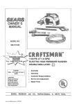
1
c-|10EC-170E
C-200E
ULTITIATC
WA?CR JE?III'G
ElectricPoweredHeavyDuty
ColdWaterHighPressureCleaner
SOLUNO|{
USERGUIDE& SPAREPARTSMANUAT
ww.dcntin.con
-d.*,
lntroductions
oftheDEN-srN C-l l0E, C-1708& C-200EHigh
onyourpurchase
Congralulations
PlcssurcCleaner.
Table of contents
Introductions
Table of contents
Clcanerthc {irst limc'
Rcadthis usermanualbefor€you start up your High Pressurc
'lhis doculnentor part of it my not be photocopied'or in any othcr way rcpntdttcctl'or
wilhouttlle priorwritlenconscntol'DEN-srN
tmnslatedto othetlanguages
w l ti r l t i n
This rnachineis a lligh Pressureclcalcr producing walcr'.iclun(lcr higlrpr$rtttc.
why severe irrjuries carr occur if thc safcty pn:cautiotrs alc nol.obscllctl'
. iil lrtth,l
i5ir"fo,. a full undcrsta'dirrgol'thc contcnlsol'this inslrucli(n)ttrtttttttlir tt'qrritrrl
to prevcnt iniurics lo you. obicclsattd pcrsotlstrcltrby
Op eral i ons
...........
2. Safety and protection information
Genemlsafety& applicationguidelines
.........................
6
.........................
8
Safety
lllrl tl txrl loll$rryld'
'thc lirllowingsylrrbols
to itxlicttlcptocr'rltttr'F
nrc urcrlirr lltir ttlttttrtnl
lo ('(lllipllltlll
u dnlttttgc
rnnyrtsultsitt pcrlotrtlirr.iul'icr
m
m
m
ir r ttctl lt' nltr l tltc lsnr L' r ul l l tl utl l tl s r l l
WARNIN( ;
prnclicc wltit:lt il'rrol lirlkrwrtl errtllclly t'rrttltlrr':ull ltt l*trtttml
iniuilcrr,
l2
15
l5
l5
ir ttrctl lo illt'll llu lcndt'l ol Fl{rt'$dllltsrtrl
CAI,JTION
tlHlll[p€
Irmcliccwhich il'not lirllowed clrrmclly eurld trtlllll lx
t0 rrrnchinc0l olhor cqttiplllclll,
NOTE is uscd to highliglrt ilnpoilnlll llllinlnnlhnl lhHl lll€y
assisltlrc rcndcrctrnyillS out lltc Pnrccrltttrrrt tttrlstrlEtttllttgllte
tcxl.
$rdlt!.JgQg20ll2
Tlrc infonnation contained in this user guide is subject to change withoul
nottce.
ffiiuiyourttlrhlr$ffillW
l . (;ctl l n g
a cq uainted with your lligh
I' r esr r tr c ( ' lt' nt tt't
Unpacking
Remove lhe lJigh Pressure Cleaner and its accessories frnm thc packing rnaterial. I:or
lr"nsport and packing reasonssome accessoriesnray be supplied disassemblcd.
Fast and efficient cleaning
'l hc DEN-SIN High PlessureClcaucrs itr llrc (
gcl rnorc clcaniugdone in lesslimc.
l ll)l (
| /(ll ( .'(,lll hrrics cttablcsyou to
'l h i s se ri e so fD E N- sr N High Pr cssur t( ' lc;tttr ' trollltr t.tt ltt l tl t l ttl t'ttttttl l ( 'cy c l i t c onl pac t
lil lI rryrlr \\ rllrir il[ 0llvrrricrrtPlflccscvcl]
dcsign.The cornpactdesign enablcslhc rrrirclrirrr.r
and tlre high perlbrnra[ccgivcs y0u lltr "|ln'tltttttl\ ltt solvt'lll llrllly 0l clcaning
al staircases,
tasks.The High PressureCleanersin lhis serier rrrerlrrtpttrrl lrrt itrlttslrtnl ntrl olliltrlc usc as
well as for cleaning contractors.All purrrplilrls. lrllilr!f, ttttrlIilx'n lrl |otllr('l willl wiltcl arc
made of non-conosive materials. 'lirgcllrcr willr llr rrrnltlr ;rr||rttr. l0ttg lik' scrtls and
stainlesssteelvalves,it ensureslong lilc arrl lttltlt rltttitlrtlttt'
Make surc all components are presenl:
o High-pressuIe machine itself
o l-landle bar (panly attached)
. WiDg nuts tor the handle bar
o Electrical cord (attached)
r High pressurehose with Spmy-gun trigger
r Double barrel lance (disassembled)
o Water inlet male hose coupling
Installation
-Attach the handle bar (pos 8, page I 6) to the machine using the wing nuts and bolts supplied,
align the handle bar according to the cabinet molding.
-Mount the high-pressure hose on to the High PressureCleaner (pos. 30 page 20) by pulling
back the retainer (pos. 24) on the high-pressure hose coupling, wlrile sliding il on tlre rnale
part (pos. 30 page 20) positioned on the front ofthe High PressureCleaner.
-Assemble the double banel spmy-lance (pos. I page 27). To mount the assembled spmylance on to the Spray-gun trigger, pull foruard the front of the Spray-gun trigger while
sliding in the male swivel coupling parl (pos. l3 page 27) ofthe spray-lance.
-Prepare the water supply for the High PressureCleaner. by attaching a hose to tlre supplied
low pressure inlet rnale-coupling. Connect the other end of tlre water supply lrose to a
potable water tap. Open the tap.
Applications
Theseheavy-dutyHigh PressurcCleancrsatt capablcol rcltrrvittll ntrv Litrl ol tlirl:
Notice: Connection to the public mains water supply according to regulations.
Algae olT concrctcconstrucliolls
Paint and grafliti ofl'walls
Dust, dirt, soil & mud oll'lloots
Oil & greaseoffengines and othcr ntcclulticnl prrls
Dirt and salt deposits off ship dccks
And with the option for use ofaccessories even many morc jobs arc to bc dcall wilh:
Sand-blasting
Dmin-cleaning
Dispensing of soapsand clremicals
Sludge pumPing
Extra long lances for hard to reaclr places
Floor cleaning equipment
Rol,ary bruslres
This rnachine is only to be used for tlre purposes it is designed for. Any other
use slrall be considered impreper and therefore potentially dangercus. The
manufacturer is not to be held responsible for arry damages causedby irnproper
use.
-Before staning the machine, bleed out air by pulling the trigger-gun handle until any air lras
escapedthe inlet hose.
-Put the power-plug into a main power supply socket. Tunr on tlre power and the High
PressureCleaner by tuming the knob (pos. 9 page I 6) clockwise to the I position.
-The high pressure cleaner is now ready for operation. The spray-gun lance is affected by a
recoil force during opemtion - therefore keep a finn grip with both hands on the Spray-gun
handle and tlre lance. Presstlre trigger and stafi cleaning.
-Tlre pressure can be regulated by tuming the high-pressure cock on dre spray-gun lance.
When using chemical injector, pressuremust be adjusted to low.
Make sure your local power supply specifications are in accordance with the
moton requirement. Refer to the lD-plate on the rnachine. Do Not run the lligh
Pressure Cleaner without sufficient potable water supply as it can cause
cavitation and serious damage to intemal pump parts. Do not let the maclrine
recycle the water (running with Spray-gun trigger not activated) for more than
a few minutes. this can cause serious darnase to the seals.
Operations
To prevent accidents lrctn happening, ensure the safely of the person(s) who
uses the equipment and to protect bystanders and nearby placed invenlory or
machinery, a few safety precautions needs attention.
2. Safcty and protection
l)
r)
Tr€at the machine as a high-speed cutting tool.
2)
Anyone under the age of l 8 is NOT allowed to use the machine.
3)
Always use a proper plug and socket specially designed with ground to earlh wiring'
4)
Only connect to an installation witlr earth wiring. A certified electrician slrall nrakc lhc
inst;llation. It is strongly recommended that the electric supply to the machinc includc a
Residual Curent Device/GFCl.
s)
6)
Always keep the High Pressure cleaner and its accessoriesin good workirrg condilion.
Clreci<the machine for defects, especially the insulation on the electric cablc. l)o NOI'
start up the machine if there is arry defecl. Have the mchirre sewiced'
When using the High PressureCleaner and iE accessories,eye protecliolr lllusl bc wolll
to protect against repelling or ricoclreting matters causing eye dalnage.
7) Suitable clothing and footwear must be wom while using the equiprnctrl l() pl('lccl llre
operator. Do not try to clean clothes or footwear with the machine.
8) Precautions must be made to keep byslanders away from the workilg rangc
e)
Do NOT spmy-clean on younelf, others or live animals. The
high-pressurebeatns are capable ofmakhrg severe injuries.
t 0 ) Do NOT spray at electrical equipment OR the machine itsell
l t ) Wlrile repairing or seruicing the equipment and its accessories always makc surc lllc
machine is tumed offand disconnected from the main power supply'
r2)Only
allow instructed personnel to opemie the machine.
l 3 ) Activating the trigger/gun can cause backward force therefore always hold spray lattcc
with both hands.
information
General safety & application
guidelines
lt is not allowed to clean asbestos containing surfaces wilh high-pressurc. unless using
special equipment.
2) Pemonsunder the influence of alcohol, drugs or rnedicine should nol opemte the machine.
3) Do not touch plug and socket with wet hands.
4) This rnachine has been constructed for use with Nilfisk-ALTO detergents. Thc use of
other detergentsor clrcmicals may cause problems as to the operation and the safety.
5) When using delergents the instructions should always be strictly obserued.
6) Always flush the machine with clean water after use of chemical/deteryents.
7) Always unplug power supply when cleaning and maintaining the machine.
E) Do not use the machine if imporlant parts are damaged - i.e. safety devices, high-pressure
hoses,spmy handle.
9) The user is obliged to obserye all national working environment and working safety
regulations conceming "opemtion of higlr-pressurewashere".
l0) lt is not allowed to connect this machine directly to a potable water supply.
ll)lftlre
machine is to be connected to potable water supply it is strictly necessaryto fit the
rnachine with a water break tank. in accordancewith ENl 7l 7.
Safety devices
The rnachine is equipped with the followirrg safety devices:
l) Stop button. The stop button (pos. 9 page 16) stops the machine when tumed anticlockwise to the 0 position.
2) locking device on spray-gun handle. The locking device prevents tlre trigger frcrn being
activated when pulled out.
Locking
14) when pausing during operation. tumed off the main switclr of the rnachine atrd ensutcs
that the trigger/gun is locked.
l5) Only use high-pressurelroses,connections and nozzles specified by DEN-SrN
- Do not use the maclrine in a possible explosive enviroDmelll ill
16) IMPORTANT
accordancewith EN-50014.
3) Themal sensor and over load relay. The thennal sensor and the overload relay protects
the motor against overloading. The machine can be switched on again afler a few minutes,
when the sensor has cooled.
DO
DON'T
a#*-
l
,:ii,llg
lmportant
medical information
Safety precautions
lrrrlrcdialchospitalattentionshouldbe given penonnel wlro sustainequipurentIelatcd iniuries
whilc opcratingtlte syslem.ln suclr cases,it is vilal lhat medical pemontrelbe apprisedof all
l'acts rclcvant to such iniuries. Thefefore. all operating persotrnel should be pI'ovided with
waterproof enrergency uredical alert tags or cards, describing llle nature ol their work and the
possibility of injury inherent in the use of water jettitrg equipmenl. The below exalnple of a
standardcard can be pholo copied, laminated and used as nedical alert tag.
IMPORTANT
MEDICAL INFORMATION
wARNTNG
lnform the doclor ofthe causeof the
injury.
Head protation- Helmets must be wom al all time by
personnel within the work area.
Helmel rmterial must be able to withstand meclranical
shock exceeding I 0G in 8rns withoul fracturing.
HEADPFOTECTION
Hand protection- Shear proof gloves nust be wom by
the opemtor al all tirnes. A glove cornbination of a cloth
inner lining and a water tight outer layer is prel'ened.
Show this card to the d@tor.
MEDICALALERT
NOTETO PHYSICIAN
nmy hc suflLfiB lioN s walltiol
injury livalualiil {nd D[tragqilsil fi\!)d
pffillcl Dilt ol a gunshol nijury. lht cilcnill
nuriD$dioils ol llc iri!ry crnrol U usd t'
pru{icl lhc c\l$1 af inlcmnl &Nilgc hilirl
and
nunrteDcnl should hcludc $rbilizlin
a tho()ugh ncun,uscular usiDirthr.
x{ays caDk u$cd h rccc$ subourilcous air
ind lbrcigil bodics dhtaill lionr lhc silo of
injury. lDiurics h lhc cslr$rilits crr i'r\dvc
cxtdiivc ncrfc, trrusclc, vc$cl dunec. as
wcll ns crust r di$ilI conrnnnNcDl sydo)c.
hjurics tt thc lorso ciD h\(n!c ir{orrrl
otaD &flu8c. Suqicil qtrsullalin d()ukl
rDd
Aggrcssilc iriSrlin
bc oblrined
dcbridcilrill is rccoNncDdcd.
Eye protection- Operalors must wear vison and goggles
to guard againsl spray and flying debris. A combination of
both goggles and visor is advisable. And will prclect the
eyes and the face during both water-blasting as well as
abrasive water-blasting
#j:"T:i;:ii,?:Tll"f,:n
pressure wate jetting equiPmenl.
Obtain medical treatmcnt
imfredialcly for ANY high-pressure
wat€rjet injuries.
'l his Flisx
The.lbllowirtg prcteclirc clotlting and devices sltould be worn botlt b.t'
personnel operaling lhe woler blaster s.t,sten and equipnrenl and b.t'those
working nearb.t,:
Suryi{al dcconrprcssn)nand crpktralir $rv
also bc Dcccssiry' ADgiogfirphic inigaliD
il'
sludics arc rsonDcndcd prc{Psali'olv
nncial iriury is susPcld llaDdae$ wilh I
(M8SO,
rnd
rolulnni
lylroscolic
byfsbrric oxv8.1t tcahcnl havt bsn usd
is rdjunolilc thcrapv h dercasc !rnr, cdoDtr
ild subcuhDlous cnnhvscDra
N'lI
uDcoilnnon
iltulktrN
rnrusuill
o4NisD$ nr nnnrunocontpcldn prucDlt hdlc
hcD sc$; lhc $urcc ol lhc watlr is
iDponrnl ir dccidiB on nrilirl $lplic
sPcdrunr
anlibidic builsrcDl, aDd Inrd
h
sfiould
atrlibidics
inmvcnoui
ildrrlriscrcd
(lullurc$ i$uldbcobuncd
Foot protection- Safety footwear witlt steel toecaps
minimum 0.5rmn (0.02") thick must be worn. The toecap
must cover al least 30% of the footwear length. Basic
safety footwear must also be equipped with metatanal
guards to protect the instep. Safety boots are available in
other desirns tlran the illustmtion.
FOOT PROTECIbN
Hearing protection- Operators and ollrer pesotrnel
exposed to noise levels of more than 90-dBa for more
than I hour must wear suitable ear protection. Ear plugs or
ear rnuffs are usually sufficient.
HEARINGPROTECTIOiI
Body protection- Waterproof gannents protect tlle
operator only from spray and flying debris. They do NOT
deflect direct jet impact. Therefore, an operator must take
care never to point a water-jet either at tlrem selves or
other personnel.
ffi
U
3. Maintenance and troubleshooting
Maintenance
Lubrication
BeJbre starting the pmp
Trouble
When the main
switch is turned on
the lligh Prcssurc
Cleaner will not
run,
The motor is
humming but the
pump does not start,
check the oil level h the punp.
oil alier lhe.first 50 working hours and llrcn olier every 500 rnrking
lnurs.
Renewal of oil: Tum off the High Pressure Cleaner. Dislnount tlre
hexagon screw at the bottom ofthe purnp housing (pos. 28 page Error!
Bookmark not defined.). Allow the oil to drain inlo a waste oil{my.
Remounl the lrexagon screw and add oil tlrrough the oil inlet on top of
tlre purnp (pos. 14 page Error! Bookmark not defined.) until the red
point of the oil control glass has been reached. Approx. 0.4kg of oil,
type SAE 15W40, is to be used.
Use a danp clolh lo wipe the cabinel and handlebar. Do not use
detergent clean in g chenicals.
Notice: To prevent electrical shock. DO NOT SPRAY DIRECTLY
UPON THE MACHINE WITH HIGH PRESSURE.
Occasionally clean lhe Jitn cover positioned at lhe back ol lhe molor to
ensure xtflicient aillow.
Do NOT operate lhe nmchine wilh damaged or removed.fint cover.
Inspection
Storage
Make sure thc socket is inserled conectly. Inspcct cord lbr cracks
and wean. Check ifluse is blown, replaceifnecessary.
Too low voltage, one phase is missittg (on lhree phase nodel only)
Itigh-pressn'e ptuup is blocked.
Check the mains voltage.
Check the connection box voltage with a meter.
With the machine tumed off, tum the motor, at the fan, if it rernains
blocked check the pump.
Notice: Do not disoose ofused oil in drain.
Cleaning
F-oull sonev,here in the power xtppl.t,.
To prcvent electriml shock and spills oJ leakfug waler. Check
electrical cord and high pressure hose ./it' wear and cmcks. Keep
conpling parts ./iee ol'dirt to ensure long lilb ol O-ring seals prevenling
water leaks.
Notice: To prevent damage on hoses and cord, be careful not to have
them run over by heavy vehicles or squeezed in door openings etc.
Replace ifnecessary.
Be sure the cleaner is kept frost-free, ifnot possible flush the purnp of
the cleaner with antifreeze fluids.
The pressure drops
and thc High
Pressure Cleaner
works irregularly.
The slrcirt.lilter is cloggecl or lhe water suppllt.fion
insrlJicient.
The pump
continuously stops
and starts, when the
spray-gun trigger is
activated.
The high pressnre nozzle is partly clogged.
lhe lap is
Clean the strain water filter.
lf there isn't enouglr water-flow through the tap, the machine
should suck from a filled water vat or tank.
Tunr off the High Pressure Cleaner, dismanlle the high-pressure
nozle and remove the extraneous matter. Replace ifdamaged.
The high prcsure
cleaner does not
reach the proper
working prssure
when the spray-gun
handle is activated.
The high-pressnre nozzle is clogged or lhere is dirt in lhe bv-WSS
valve. Thepunrp sttcksair'.
The High Pressure
Cleaner only works
with approximately
2/3 of the maximum
pr€ssure, and the
high-pressure hose
is vibrating.
There is dirl itt lhe valves.
Tum off the High Pressure Cleaner. Clean tlre nozle. Inspect the
low pressuresupply,
or while the spray-gun lrigger is activated tum the maclrine on
again. Repeal the procedure again; now with the trigger released. If
the prcblem still occurs, the by-pass valve should be dismantled
and tlre extraneousmatter removed.
Tum off the High PressureCleaner. Dismantle the valve bolts and
the valves, remove tlre dirt and check to ensure the valve flaps are
movable and fits tightly.
(Contimrcs)
1,
I
Service instructions
Noisiness
The punp sucks air. One or nore valve springs are brcken or
down. Extmneous natter in lhe valves. Crunkcase or,ttolor
bearings worn oul.
Detach the high pressure lrose, dump back hose. inlet hose, sal'ety valve. and parls on tlre
purnp head before sewing the pump.
(Please refer to Purnp assernbly(Page I 7) unless otheruise stated.)
Inspect the low-pressure supply. Replace springs. Clean tlre valves.
Replace the bearings.
Water in the oil
The Ot'ittg casing is woril out. High noistw.e in the air
(condensing insfule the crankcase) The seals are completely wont
oltt.
Check or replace the O-ring.
Renewal of the cmnkcase oil more often.
Replace tlre seals.
When using chemicalinjector
The High Pressure
Cleaner do€s not
suck chemicafs
The chemical container is enpty. The High Pressure Cleaner has
not been set to low-pressure (on lhe double barrel lance cock). The
low-prcsnre nozzle is clogged, or partly clogged. The non-renffn
valve oflhe chenrical injector is shtck.
Servicing the valves:
Remove the Yalvecap(Pos: 2).
Inspect the valve cap O-Ring (Pos:I ) for any damage,replace if necessary.
Use the needle nose pliere to remove the valve (Pos: 3).
Use a small probe to move the poppet up and down to assure ihat the valve is
funclioning properly and that no debris is stuck in the valve (Pos: 3).
5. To reassemble tlre valves proceed the olher way rcund and tighten the cover screws
with a torque wrench. (Refering to torque specification)
l.
2.
3.
4.
Servicing the Packing/Seals:
Rernove the bolts (Pos: 38) on the head (Pos: 36) ofthe pump.
Place the screwdriven between the head (Pos: 36) and crankcase(Pos: 9) ofthe pump,
lifting one up and the otherdown. The head should slart to lift offofthe plungem (Pos:
23).
Ensure the chemical container contail'ls sufficient fluid for proper
suction.
Set the spraylance to low pressureby turning the cock on the lance
counterclockwise.
Clean or replace the low-pressure nozzle.
Clean, correct or replace the non-retum valve of the chemical
injector.
For any further inconveniences, not menlioned in tlris user guide or any
damages of the machine, we strongly suggesl you to make contact with your
dealer for the repair or possible replacernenlofany original spare-parts.
When you remove the head, some ofthe water seals llave stayed on the plungen (Pos:
23) and some in the head (Pos: 36). To remove the seals from the plungen (Pos: 23).
simple tum the assembliesand pull off.
t:f{ri:ii:irr.ill]ljitltlli$rw
tiirr$lir|llrlill;llliri
"' thna;nisiidittt*'dCIi
be$ht'dit&idi.riitilllirlll'llL$l.1,iil
|,'
Pump bcad (Pos: 36) lo drive cnd (Pos: 9) lnstallation:
Il'the seal assemblies(Pos: 30-33) arc in thc hcad (Pos: 36) usc thc rcversiblcpliers to
gmb the seal rclaiuer on the outsidering, lwist the rclainer in cither dirtction and lili
out.
5. Pull out the guide ring (Pos:31) with your finger.
6. Pull the high-pressure seal (Pos: 30) and support ring(Pos: 7) out ofthe head with your
finger.
7. The low-pressure seal (Pos: 33) is located in the brass seal retainer. Using the
mechanics pick, go in between the seal and rctaincr and pull the seal stmighl out.
8. Remove tlre seal retainer O-Ring (Pos: 32) witlr mechanics pick.
9. To reassernble the packing arrd seals proceed the otlrer way round and tighten the
cover scrcws with a tolque wrench. (Refening to torque specificalion)
|.
I u rrrt h c c ra rrk s l ra l o
l a l i ! n l l rc
Place the head evenly onto the plungers and push it until it makes contact with tlle
drive end of the
Servicing the Plungcrs (Pos: 23):
Recomrnend to replace Piston kits, Support Rings kits, and Water Seals kits whenever
sewicing the plungers.
3. Torque thc head bolts (Pos: 38) as shown in the tighlening sequenccdiagram
l. Rernovetlre plungerrctainernut (Pos:25).
2. Inserl the gasketscraperbelween the copperwasher(Pos:24) and plunger (pos: 23) to
removc tlre washer (Pos: 22).
3. 1'wist and pull the plunger off the plunger rod.
Torque Specification:
Descriptions
In.lbs
Ke.rn/N.m
Remove the plunger rod O-Ring (Pos: 21) wilh the mechanics pick.
5 . Remove the washer (Pos: 22). And clcan any thread locker that is left on the plunger
rod and retaining nut tlrreads.
6 . To reassemblethe plungen, proceed the other way round and tighten the cover screws
with a torque wrench. (Refening to torque specification)
Ilead t Pos:
133
l5
PistonNut (Pos:25)
106
t2
Valve Cap (Pos:2
442
50


![LS5105 Document No 2 [PDF 1MB] - Australian Electoral Commission](http://vs1.manualzilla.com/store/data/005655823_1-2458abda02bbd8390d0ac9ba8bd86ac6-150x150.png)