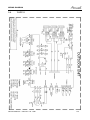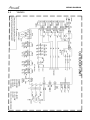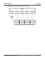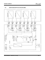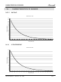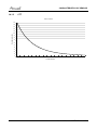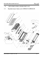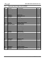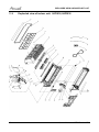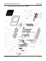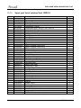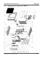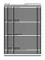
1
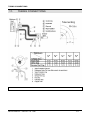
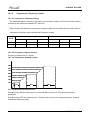
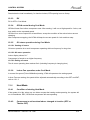
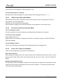
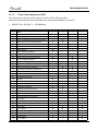
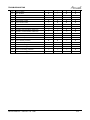
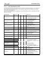
YBZ214-318-430
Indoor Units
AWSI-HZD009-H11
AWSI-HZD012-H11
AWSI-HZD018-H11
Outdoor Units
AWSI-HYD009-H11
AWSI-HYD012-H11
AWSI-HYD018-H11
AWAU-YBZ214-H11
AWAU-YBZ318-H11
AWAU-YBZ430-H11
REFRIGERANT
R410A
SM YBZ H11 1-A.1 GB
Version:2
HEAT PUMP
JUNE- 2011
LIST OF EFFECTIVE PAGES
LIST OF EFFECTIVE PAGES
Note: Changes in the pages are indicated by “Revision #” in the footer of each effected page
(when none indicates any changes in the relevant page). All pages in the following list represent
effected/ non effected pages divided by chapters.
Dates of issue for original and changed pages are:
Original ....... 01........ 14 Nov, 10
Total number of pages in this publication is 85 consisting of the following:
Page
No.
Revision
No. #
Page
No.
Revision
No. #
Page
No.
Revision
No. #
* Zero in this column indicates an original page.
A
Service Manual –YBZ DCI 1-A.1 GB
TABLE OF CONTENTS
Table of Contents
1.
INTRODUCTION ............................................................................................................................. 1-1
2.
PRODUCT DATA SHEET............................................................................................................... 2-1
3.
RATING CONDITIONS ................................................................................................................... 3-1
4.
OUTLINE DIMENSION ................................................................................................................... 4-1
5.
PERFORMANCE DATA ................................................................................................................. 5-1
6.
PRESSURE CURVES..................................................................................................................... 6-1
7.
SOUND LEVEL CHARACTERISTICS ........................................................................................... 7-1
8.
ELECTRICAL DATA....................................................................................................................... 8-1
9.
WIRING DIAGRAM......................................................................................................................... 9-1
10.
REFRIGERATION DIAGRAMS ...................................................................................................... 10-1
11.
TUBING CONNECTIONS ............................................................................................................... 11-1
12.
CONTROL SYSTEM ....................................................................................................................... 12-1
13.
TROUBLESHOOTING.................................................................................................................... 13-1
14.
CHARACTERISTICS OF SENSOR................................................................................................ 14-1
15.
EXPLODED VIEW & SPARE PART LIST...................................................................................... 15-1
Service Manual – YBZ DCI 1-A.1 GB
i
INTRODUCTION
1.
INTRODUCTION
1.1
General
The YBZ DC inverter multisplits outdoor is a multi-tubing system with 2, 3 or 4
connected indoor units. The multi-split inverter is a high level technology product for
residential and commercial application offering comfort, low noise operation and
energy saves.
.
1.2
Main Features
The unit benefits from the most advanced technological innovations, namely:
• DC inverter technology.
• R410A models
• Microprocessor control and indoor LED display
• High COP, Energy efficiency class A in cooling/heating mode
• Max allowing total tubing distance of 70m(for model 18,30)
• Up to 10 m vertical high between indoor and outdoor units(for model 18,30)
• Easy installation and service.
• Sleep mode from remote control to save energy
• ON/OFF timer and clock display
• Vertical auto swing with motorized flap (any position stop)
• Intelligent Deicing
• Memory from power failure
• Rapid cooling/heating
• I-Feel function
• Cold air prevention in heating
• Clean function (Blow dry)
• Self diagnostic (Error indications) for ease of maintenance
Service Manual – YBZ DCI 1-A.1 GB
1-1
INTRODUCTION
1.3
Indoor Unit
The indoor unit is wall mounted, and can be easily fitted to many types of residential
locations. It includes:
• LED display
• Variable speed with PG motor
• Motorized flap
• High efficiency filtration to ensure a best Air Quality: Advanced filtering combine
mechanical, Photo-catalytic + Bi-anti bacterial and observe bad gaseous and
smokes.
1.4
Control
The microprocessor indoor controller, and an infrared remote control, supplied as
standard, provides complete operating function and programming.
Remote control RC 8:
Compact and economically design, it offers excellent user comfort. Combining modern design
with high technology, the RC8 remote control offers powerful functions of real considering of user
comfort and energy saving of air-conditioner.
For detail of functions, please refer to Appendix 1
1-2
Service Manual – YBZ DCI 1-A.1 GB
INTRODUCTION
1.5
Outdoor Unit
The outdoor units can be installed as floor or wall mounted units by using a wall
supporting bracket. The metal sheets are protected by anti- corrosion paint work
allowing long life resistance. All outdoor units are pre-charged. For further information
please refer to the Product Data Sheet, Chapter 2.
It includes:
• Compressor mounted in a soundproofed compartment :
• Axial fan.
• Outdoor coil with hydrophilic louver fins for RC units.
• Outlet air fan grill.
• Interconnecting wiring terminal block.
• Electric expansion valves to control the refrigerant to each indoor.
1.6
Tubing Connections
Flare type interconnecting tubing to be produced on site.
For further details please refer to the Installation Manual.
1.7
Inbox Documentation
Each unit is supplied with its own installation, operation and remote control manuals.
Service Manual – YBZ DCI 1-A.1 GB
1-3
INTRODUCTION
1.8
Matching Table
INDOOR UNITS
AWSI-HZD009-H11
AWSI-HZD012-H11
AWSI-HZD018-H11
X
X
X
X
X
X
X
X
OUTDOOR UNITS
AWAU-YBZ214-H11
AWAU-YBZ318-H11
AWAU-YBZ430-H11
INDOOR UNITS
OUTDOOR UNITS
AWSI-HYD009-H11
AWSI-HYD012-H11
AWSI-HYD018-H11
X
X
X
X
X
X
X
X
AWAU-YBZ214-H11
AWAU-YBZ318-H11
AWAU-YBZ430-H11
1-4
Service Manual – YBZ DCI 1-A.1 GB
INTRODUCTION
1.9
Indoor unit combination
AWAU-YBZ214-H11
ELAU-VBZ214-H11
JOAU-ZBY214-H11
1 unit
2 units
9
9+9
12
9+12
AWAU-YBZ318-H11
ELAU-VBZ318-H11
2 units
9+9
9+12
3 units
9+9+9
9+9+12
9+9+18
9+18
12+12
9+18+18
9+12+12
9+12+18
12+18
18+18
12+12+12
12+12+18
12+18+18
AWAU-YBZ430-H11
ELAU-VBZ430-H11
2 units
3 units
4units
9+9
9+12
9+9+9
9+9+12
9+9+18
9+9+9+9
9+9+9+12
9+9+9+18
9+18
12+12
9+18+18
9+12+12
9+12+18
9+9+12+12
9+9+12+18
9+9+18+18
12+18
18+18
12+12+12
12+12+18
12+18+18
Service Manual – YBZ DCI 1-A.1 GB
9+12+12+12
9+12+12+18
9+12+18+18
12+12+12+12
12+12+12+18
12+12+18+18
1-5
PRODUCT DATASHEET
2.
PRODUCT DATA SHEET
Model Outdoor Unit
Installation Method of Pipe
Characteristics
Capacity (4)
Power input (4)
EER (Cooling) or COP(Heating) (4)
Energy efficiency class
YBZ214
Flared
Units
kW
kW
W/W
V
Ph
Hz
A
Power supply
OUTDOOR
Rated current
Power factor
Prated (IDU+ODU)
Starting current
Circuit breaker rating
Refrigerant control
Compressor type, model
Fan type & quantity
Fan speeds
Air flow
Sound power level
Sound pressure level(3)
Dimensions
Net Weight
Package dimensions
Packaged weight
Refrigerant type
W
A
A
H
H
H
H
WxHxD
WxHxD
Standard charge
Additional charge
Liquid line
Suction line
Max.tubing length
Connections height difference
between units between indoor units
height difference
between indoor &
outdoor
Service Manual – YBZ DCI 1-A.1 GB
RPM
m3/hr
dB(A)
dB(A)
mm
kg
mm
kg
Cooling
Heating
3.90(2.00-4.70)
4.30(2.50-5.50)
1.14(0.50-2.00)
1.13(0.58-2.15)
3.42
3.80
A
A
220-240
1
50
5.11
5.06
0.97
0.97
25
EEV
Sanyo Twin Rotary,C-6RZ146H1A
Propeller(direct) x 1
880/700/500
2600/2300/1600
66
56
899X596X378
43
980X420X645
48
R410A
kg
1.4
In.(mm)
In.(mm)
m.
20g/m(10m<L<20m)
2x1/4"(6.35)
2x3/8"(9.53)
Max.10m for one unit and 20m for total
m
Max. 5
m.
Max. 5
2-1
PRODUCT DATA SHEET
Model Outdoor Unit
Installation Method of Pipe
Characteristics
Capacity (4)
Power input (4)
EER (Cooling) or COP(Heating) (4)
Energy efficiency class
Power supply
OUTDOOR
Rated current
Power factor
Prated (IDU+ODU)
Starting current
Circuit breaker rating
Refrigerant control
Compressor type, model
Fan type & quantity
Fan speeds
H
Air flow
H
Sound power level
H
Sound pressure level(3)
H
Dimensions
WxHxD
Net Weight
Package dimensions
WxHxD
Packaged weight
Refrigerant type
Standard charge
Additional charge
Liquid line
Suction line
Max.tubing length
Connections
between units height difference between
indoor units
height difference between
indoor & outdoor
2-2
YBZ318
Flared
Units
kW
kW
W/W
V
Ph
Hz
A
W
A
A
Cooling
Heating
6.80(2.20-10.00)
8.00(2.80-11.00)
2.11(0.65-4.50)
2.21(0.98-3.95)
3.22
3.62
A
A
220-240
1
50
9.45
9.90
0.97
0.97
In.(mm)
In.(mm)
m
32
EEV
Mitsubishi Twin Rotary,TNB220FLHMC
Propeller(direct) x 1
690/600/500
3300/2900/2400
68
58
955X700X396
59
1029X458X750
64
R410A
2.2
20g/m(30m<L<70m)
3x1/4"(6.35)
3x3/8"(9.53)
Max.20m for one unit and 70m for total
m
Max. 10
m
Max. 10
RPM
m3/hr
dB(A)
dB(A)
mm
kg
mm
kg
kg
Service Manual – YBZ DCI 1-A.1 GB
PRODUCT DATASHEET
Model Outdoor Unit
Installation Method of Pipe
Characteristics
Capacity (4)
Power input (4)
EER (Cooling) or COP(Heating) (4)
Energy efficiency class
YBZ318
Flared
Units
kW
kW
W/W
V
Ph
Hz
A
Power supply
OUTDOOR
Rated current
Power factor
Prated (IDU+ODU)
Starting current
Circuit breaker rating
Refrigerant control
Compressor type, model
Fan type & quantity
Fan speeds
Air flow
Sound power level
Sound pressure level(3)
Dimensions
Net Weight
Package dimensions
Packaged weight
Refrigerant type
W
A
A
H
H
H
H
WxHxD
WxHxD
Standard charge
Additional charge
Liquid line
Suction line
Max.tubing length
Connections
height difference
between units
between indoor units
height difference
between indoor &
outdoor
Service Manual – YBZ DCI 1-A.1 GB
RPM
m3/hr
dB(A)
dB(A)
mm
kg
mm
kg
Cooling
Heating
7.80(2.20-10.00)
8.70(2.80-11.00)
2.42(0.65-4.50)
2.40(0.98-3.95)
3.22
3.63
A
A
220-240
1
50
10.8
10.7
0.97
0.97
32
EEV
Mitsubishi Twin Rotary,TNB220FLHMC
Propeller(direct) x 1
690/600/500
3300/2900/2400
68
58
955X700X396
60
1029X458X750
65
R410A
kg
2.2
In.(mm)
In.(mm)
m.
20g/m(40m<L<70m)
4x1/4"(6.35)
4x3/8"(9.53)
Max.20m for one unit and 70m for total
m.
Max. 10
m.
Max. 10
2-3
PRODUCT DATA SHEET
Model Indoor Unit
Installation Method of Pipe
Characteristics
Capacity (4)
HZD/HYD009
Flared
Units
kW
V
Ph
Hz
Power supply
INDOOR
Fan type & quantity
Cooling
Fan speeds
Heating
Air flow (1)
External static pressure
Sound power level (2)
Sound pressure level(3)
Moisture removal
Condensate drain tube I.D
Dimensions
Net Weight
Package dimensions
Packaged weight
Operation control type
SH/H/M/L
SH/H/M/L
SH/H/M/L
Min
SH/H/M/L
SH/H/M/L
WxHxD
WxHxD
Model Indoor Unit
Installation Method of Pipe
Characteristics
Capacity (4)
INDOOR
2-4
Heating
2.80
220-240
1
50
Crossflow x 1
1300/1100/900/700
1300/1140/980/820
600/500/350/280
0
51/48/40/34/41/38/30/24/0.8
16
770x283x201
8
844x342x261
11
Remote control
HZD/HYD012
Flared
Units
kW
V
Ph
Hz
Power supply
Fan type & quantity
Cooling
Fan speeds
Heating
Air flow (1)
External static pressure
Sound power level (2)
Sound pressure level(3)
Moisture removal
Condensate drain tube I.D
Dimensions
Net Weight
Package dimensions
Packaged weight
Operation control type
RPM
RPM
m3/hr
Pa
dB(A)
dB(A)
l/hr
mm
mm
kg
mm
kg
Cooling
2.60
SH/H/M/L
SH/H/M/L
SH/H/M/L
Min
SH/H/M/L
SH/H/M/L
WxHxD
WxHxD
RPM
RPM
m3/hr
Pa
dB(A)
dB(A)
l/hr
mm
mm
kg
mm
kg
Cooling
3.50
Heating
3.80
220-240
1
50
Crossflow x 1
1350/1150/950/750
1350/1190/1020/850
680/560/410/300
0
52/49/41/35/42/39/31/25/1.5
16
770x283x201
9
844x342x261
12
Remote control
Service Manual – YBZ DCI 1-A.1 GB
PRODUCT DATASHEET
Model Indoor Unit
Installation Method of Pipe
Characteristics
Capacity (4)
HZD/HYD018
Flared
Units
kW
V
Ph
Hz
Power supply
INDOOR
Fan type & quantity
Cooling
Fan speeds
Heating
Air flow (1)
External static pressure
Sound power level (2)
Sound pressure level(3)
Moisture removal
Condensate drain tube I.D
Dimensions
Net Weight
Package dimensions
Packaged weight
Operation control type
SH/H/M/L
SH/H/M/L
SH/H/M/L
Min
SH/H/M/L
SH/H/M/L
WxHxD
WxHxD
RPM
RPM
m3/hr
Pa
dB(A)
dB(A)
l/hr
mm
mm
kg
mm
kg
Cooling
5.30
Heating
5.80
220-240
1
50
Crossflow x 1
1300/1100/950/800
1400/1200/1050/900
800/680/560/460
0
55/50/47/42/45/40/37/32/2
16
865x305x215
12
948X383X310
16
Remote control
(1)Airflow in ducted units; at nominal external static pressure.
(2)Sound power in ducted units is measured at air discharge.
(3)Sound pressure level measured at 1-meter distance from unit.
(4)Rating conditions in accordance to ISO 5151 and ISO 13253 (for ducted units).
Service Manual – YBZ DCI 1-A.1 GB
2-5
RATING CONDITIONS
3.
RATING CONDITIONS
Rating conditions in accordance with ISO 5151 and ISO 13253 (for ducted units).
Cooling:
Indoor:
27oC DB 19oC WB
Outdoor: 35 oC DB
Heating:
Indoor:
20oC DB
Outdoor: 7oC DB 6oC WB
Operating Limits
R410A
Upper limit
Lower limit
Upper limit
Heating
Lower limit
Cooling
Voltage
Service Manual – YBZ DCI 1-A.1 GB
Indoor
32 C DB 23oC WB
21oC DB 15oC WB
27oC DB
10oC DB
o
Outdoor
43 C DB
-5oC DB
24oC DB 18oC WB
-15oC DB RH80%
o
1-PH 50Hz 195 – 265 V
3-1
OUTLINE DIMENSION
4.
4.1
OUTLINE DIMENSION
Indoor: HZD009, HZD012, HYD009, HYD012
Service Manual – YBZ DCI 1-A.1 GB
4-1
OUTLINE DIMENSION
4.2
4-2
Indoor: HZD018, HYD018
Service Manual – YBZ DCI 1-A.1 GB
OUTLINE DIMENSION
4.3
Outdoor: YBZ214
Service Manual – YBZ DCI 1-A.1 GB
4-3
OUTLINE DIMENSION
4.4
4-4
Outdoor: YBZ318, YBZ430
Service Manual – YBZ DCI 1-A.1 GB
PERFORMANCE DATA
5.
PERFORMANCE DATA
5.1
YBZ214
5.1.1
Cooling Capacity (kW)
ID COIL ENTERING AIR DB/WB TEMPERATURE [C0]
OD COIL ENTERING
AIR DB
TEMPERATURE [C0]
-10 - 20
(protection range)
25
30
35
40(Protection Range)
46(Protection Range)
DATA
TC
SC
PI
TC
SC
PI
TC
SC
PI
22/15
TC
SC
PI
TC
SC
PI
TC
SC
PI
3.41
3.26
1.10
4.18
3.63
0.90
3.80
3.44
1.00
24/17
27/19
29/21
80 - 110 % of nominal
80 - 105 % of nominal
25 - 50 % of nominal
4.43
4.67
4.92
3.72
3.80
3.89
0.91
0.93
0.95
4.04
4.29
4.53
3.53
3.62
3.70
1.02
1.04
1.05
32/23
3.66
3.90
4.14
3.35
3.43
3.52
1.12
1.14
1.16
80%-92% of nominal
80%-92% of nominal
80%-92% of nominal
70%-85% of nominal
70%-85% of nominal
90%-100% of nominal
4.39
3.60
1.18
5.16
3.98
0.97
4.77
3.79
1.07
LEGEND
TC
SC
PI
WB
DB
ID
OU
5.1.2
–
–
–
–
–
–
–
Total Cooling Capacity, kW
Sensible Capacity, kW
Power Input, kW
Wet Bulb Temp., (oC)
Dry Bulb Temp., (oC)
Indoor
Outdoor
Capacity Correction Factors
Capacity Ration
Cooling Capacity Ratio Vs. Outdoor Temperature
1.4
1.3
1.2
1.1
1
0.9
0.8
0.7
0.6
0.5
20
25
30
35
40
45
Outdoor Temperature [deg C]
Service Manual – YBZ DCI 1-A.1 GB
5-1
PERFROMANCE DATA
5.1.3
Heating Capacity (kW)
ID COIL ENTERING AIR DB TEMPERATURE [C0]
OD COIL
ENTERING AIR
DB/WB
TEMPERATURE
[C0]
DATA
TC
PI
TC
PI
TC
PI
TC
PI
TC
PI
TC
PI
TC
PI
TC
PI
TC
PI
-15/-16
-10/-12
-7/-8
-1/-2
2/1
7/6
10/9
15/12
15-24
(Protection Range)
15
2.29
0.72
2.74
0.83
3.08
0.92
3.26
0.96
3.37
0.98
4.44
1.03
4.62
1.07
4.80
1.12
20
2.15
0.83
2.60
0.94
2.94
1.02
3.11
1.06
3.23
1.09
4.30
1.13
4.48
1.18
4.65
1.23
85 - 105 % of nominal
80 - 120 % of nominal
25
2.01
0.93
2.46
1.04
2.80
1.12
2.97
1.17
3.08
1.19
4.16
1.23
4.33
1.28
4.51
1.33
LEGEND
TH
PI
WB
DB
ID
OU
5.1.4
–
–
–
–
–
–
Total Heating Capacity, kW
Power Input, kW
Wet Bulb Temp., (oC)
Dry Bulb Temp., (oC)
Indoor
Outdoor
Capacity Correction Factors
Heating Capacity Ratio Vs. Outdoor Temperature
Capacity Ration
1.2
1.1
1
0.9
0.8
0.7
0.6
0.5
-15
-10
-5
0
5
10
15
Outdoor WB Temperature [deg C]
5-2
Service Manual – YBZ DCI 1-A.1 GB
PERFORMANCE DATA
5.2
YBZ318
5.2.1
Cooling Capacity (kW)
ID COIL ENTERING AIR DB/WB TEMPERATURE [C0]
OD COIL ENTERING
AIR DB
TEMPERATURE [C0]
-10 - 20
(protection range)
25
30
35
40(Protection Range)
46(Protection Range)
DATA
TC
SC
PI
TC
SC
PI
TC
SC
PI
22/15
TC
SC
PI
TC
SC
PI
TC
SC
PI
5.95
5.68
2.04
7.30
6.33
1.66
6.62
6.01
1.85
24/17
27/19
29/21
80 - 110 % of nominal
80 - 105 % of nominal
25 - 50 % of nominal
7.72
8.15
8.57
6.48
6.63
6.78
1.69
1.73
1.76
7.05
7.47
7.90
6.16
6.31
6.46
1.88
1.92
1.95
32/23
6.37
6.80
7.23
5.83
5.98
6.13
2.08
2.11
2.14
80%-92% of nominal
80%-92% of nominal
80%-92% of nominal
70%-85% of nominal
70%-85% of nominal
90%-100% of nominal
7.65
6.29
2.18
9.00
6.93
1.79
8.32
6.61
1.99
LEGEND
TH
PI
WB
DB
ID
OU
5.2.2
–
–
–
–
–
–
Total Heating Capacity, kW
Power Input, kW
Wet Bulb Temp., (oC)
Dry Bulb Temp., (oC)
Indoor
Outdoor
Capacity Correction Factors
Capacity Ration
Cooling Capacity Ratio Vs. Outdoor Temperature
1.4
1.3
1.2
1.1
1
0.9
0.8
0.7
0.6
0.5
20
25
30
35
40
45
Outdoor Temperature [deg C]
Service Manual – YBZ DCI 1-A.1 GB
5-3
PERFROMANCE DATA
5.2.3
Heating Capacity (kW)
ID COIL ENTERING AIR DB TEMPERATURE [C0]
OD COIL
ENTERING AIR
DB/WB
TEMPERATURE
[C0]
-15/-16
-10/-12
-7/-8
-1/-2
2/1
7/6
10/9
15/12
15-24
(Protection Range)
DATA
TC
PI
TC
PI
TC
PI
TC
PI
TC
PI
TC
PI
TC
PI
TC
PI
TC
PI
15
4.26
1.41
5.11
1.63
5.74
1.79
6.06
1.87
6.27
1.93
8.26
2.01
8.59
2.10
8.92
2.19
20
4.00
1.62
4.84
1.83
5.48
1.99
5.79
2.08
6.00
2.13
8.00
2.21
8.33
2.30
8.66
2.40
85 - 105 % of nominal
80 - 120 % of nominal
25
3.73
1.82
4.58
2.04
5.21
2.20
5.53
2.28
5.74
2.33
7.74
2.41
8.06
2.51
8.39
2.60
LEGEND
TH
PI
WB
DB
ID
OU
5.1.5
–
–
–
–
–
–
Total Heating Capacity, kW
Power Input, kW
Wet Bulb Temp., (oC)
Dry Bulb Temp., (oC)
Indoor
Outdoor
Capacity Correction Factors
Heating Capacity Ratio Vs. Outdoor Temperature
Capacity Ration
1.2
1.1
1
0.9
0.8
0.7
0.6
0.5
-15
-10
-5
0
5
10
15
Outdoor WB Temperature [deg C]
5-4
Service Manual – YBZ DCI 1-A.1 GB
PERFORMANCE DATA
5.3
YBZ430
5.3.1
Cooling Capacity (kW)
ID COIL ENTERING AIR DB/WB TEMPERATURE [C0]
OD COIL ENTERING
AIR DB
TEMPERATURE [C0]
-10 - 20
(protection range)
25
30
35
40(Protection Range)
46(Protection Range)
DATA
TC
SC
PI
TC
SC
PI
TC
SC
PI
22/15
TC
SC
PI
TC
SC
PI
TC
SC
PI
6.82
6.52
2.35
8.37
7.26
1.91
7.60
6.89
2.13
24/17
27/19
29/21
80 - 110 % of nominal
80 - 105 % of nominal
25 - 50 % of nominal
8.86
9.34
9.83
7.43
7.61
7.78
1.95
1.99
2.03
8.08
8.57
9.06
7.06
7.23
7.41
2.17
2.21
2.25
7.31
7.80
8.29
6.69
6.86
7.04
2.39
2.43
2.47
80%-92% of nominal
80%-92% of nominal
80%-92% of nominal
70%-85% of nominal
70%-85% of nominal
90%-100% of nominal
32/23
10.32
7.95
2.07
9.55
7.58
2.29
8.78
7.21
2.51
LEGEND
TH
PI
WB
DB
ID
OU
5.3.2
–
–
–
–
–
–
Total Heating Capacity, kW
Power Input, kW
Wet Bulb Temp., (oC)
Dry Bulb Temp., (oC)
Indoor
Outdoor
Capacity Correction Factors
Capacity Ration
Cooling Capacity Ratio Vs. Outdoor Temperature
1.4
1.3
1.2
1.1
1
0.9
0.8
0.7
0.6
0.5
20
25
30
35
40
45
Outdoor Temperature [deg C]
Service Manual – YBZ DCI 1-A.1 GB
5-5
PERFROMANCE DATA
5.3.3
Heating Capacity (kW)
ID COIL ENTERING AIR DB TEMPERATURE [C0]
OD COIL
ENTERING AIR
DB/WB
TEMPERATURE
[C0]
-15/-16
-10/-12
-7/-8
-1/-2
2/1
7/6
10/9
15/12
15-24
(Protection Range)
DATA
TC
PI
TC
PI
TC
PI
TC
PI
TC
PI
TC
PI
TC
PI
TC
PI
TC
PI
15
4.63
1.54
5.55
1.77
6.24
1.94
6.59
2.03
6.82
2.09
8.99
2.18
9.34
2.28
9.70
2.38
20
4.35
1.76
5.27
1.99
5.95
2.17
6.30
2.25
6.53
2.31
8.70
2.40
9.06
2.50
9.42
2.60
85 - 105 % of nominal
80 - 120 % of nominal
25
4.06
1.98
4.98
2.21
5.67
2.39
6.01
2.47
6.24
2.53
8.41
2.62
8.77
2.72
9.13
2.82
LEGEND
TH
PI
WB
DB
ID
OU
5.3.4
–
–
–
–
–
–
Total Heating Capacity, kW
Power Input, kW
Wet Bulb Temp., (oC)
Dry Bulb Temp., (oC)
Indoor
Outdoor
Capacity Correction Factors
Heating Capacity Ratio Vs. Outdoor Temperature
Capacity Ration
1.2
1.1
1
0.9
0.8
0.7
0.6
0.5
-15
-10
-5
0
5
10
15
Outdoor WB Temperature [deg C]
5-6
Service Manual – YBZ DCI 1-A.1 GB
PRESSURE CURVES
6.
PRESSURE CURVES
6.1
Model: YBZ214
6.1.1
Cooling
Suction Pressure [kPa]
1400
Indoor
DB/WB
1300
22/15
1200
24/17
1100
27/19
1000
29/21
900
32/23
800
700
10
15
20
25
30
35
40
45
Outdoor DB Temperature
Discharge Pressure [kPa]
3750
Indoor
DB/WB
22/15
3500
3250
3000
24/17
2750
2500
27/19
29/21
2250
32/23
2000
1750
1500
10
15
20
25
30
35
40
45
Outdoor DB Temperature
7.00
InputCurrent[A]
6.50
6.00
22/15
5.50
24/17
5.00
27/19
4.50
29/21
4.00
32/23
3.50
3.00
2.50
10
15
20
25
30
35
40
45
Outdoor DB Temperature
Service Manual – YBZ DCI 1-A.1 GB
6-1
PRESSURE CURVES
6.1.2
Heating
Suction Pressure [kPa]
1100
1000
900
15
800
20
700
25
600
500
400
-15
-10
-5
0
5
10
15
Discharge Pressure [kPa]
Outdoor WB Temperature
3250
3000
Indoor DB
2750
15
2500
20
2250
2000
25
1750
1500
-15
-10
-5
0
5
10
15
Outdoor WB Temperature
7.00
Input Current [A]
6.50
6.00
Indoor DB
5.50
15
5.00
20
4.50
25
4.00
3.50
3.00
-15
-10
-5
0
5
10
15
Outdoor WB Temperature
6-2
Service Manual – YBZ DCI 1-A.1 GB
PRESSURE CURVES
6.2
Model: YBZ318
6.2.1
Cooling
Suction Pressure [kPa]
1200
Indoor
DB/WB
1100
22/15
24/17
1000
27/19
900
29/21
32/23
800
700
10
15
20
25
30
35
40
45
Discharge Pressure [kPa]
Outdoor DB Temperature
4000
3750
3500
3250
3000
2750
2500
2250
2000
1750
1500
Indoor
DB/WB
22/15
24/17
27/19
29/21
32/23
10
15
20
25
30
35
40
45
Input Current [A]
Outdoor DB Temperature
13.00
12.50
12.00
11.50
11.00
10.50
10.00
9.50
9.00
8.50
8.00
7.50
7.00
6.50
6.00
22/15
24/17
27/19
29/21
32/23
10
15
20
25
30
35
40
45
Outdoor DB Temperature
Service Manual – YBZ DCI 1-A.1 GB
6-3
PRESSURE CURVES
6.2.2
Heating
Suction Pressure [kPa]
1100
1000
900
800
15
700
20
600
25
500
400
300
-15
-10
-5
0
5
10
15
Discharge Pressure [kPa]
Outdoor WB Temperature
3250
3000
Indoor DB
2750
2500
15
20
2250
2000
25
1750
1500
-15
-10
-5
0
5
10
15
Input Current [A]
Outdoor WB Temperature
13.00
12.50
12.00
11.50
11.00
10.50
10.00
9.50
9.00
8.50
8.00
7.50
7.00
6.50
6.00
Indoor DB
15
20
25
-15
-10
-5
0
5
10
15
Outdoor WB Temperature
6-4
Service Manual – YBZ DCI 1-A.1 GB
PRESSURE CURVES
6.3
Model: YBZ430
6.3.1
Cooling
Suction Pressure [kPa]
1200
Indoor
DB/WB
1100
22/15
24/17
1000
27/19
900
29/21
32/23
800
700
10
15
20
25
30
35
40
45
Discharge Pressure [kPa]
Outdoor DB Temperature
4000
3750
3500
3250
3000
2750
2500
2250
2000
1750
1500
Indoor
DB/WB
22/15
24/17
27/19
29/21
32/23
10
15
20
25
30
35
40
45
Input Current [A]
Outdoor DB Temperature
15.00
14.50
14.00
13.50
13.00
12.50
12.00
11.50
11.00
10.50
10.00
9.50
9.00
8.50
8.00
7.50
7.00
22/15
24/17
27/19
29/21
32/23
10
15
20
25
30
35
40
45
Outdoor DB Temperature
Service Manual – YBZ DCI 1-A.1 GB
6-5
PRESSURE CURVES
6.3.2
Heating
Suction Pressure [kPa]
1100
1000
900
800
15
700
20
600
25
500
400
300
-15
-10
-5
0
5
10
15
Discharge Pressure [kPa]
Outdoor WB Temperature
3250
3000
Indoor DB
2750
2500
15
20
2250
2000
25
1750
1500
-15
-10
-5
0
5
10
15
Input Current [A]
Outdoor WB Temperature
15.00
14.50
14.00
13.50
13.00
12.50
12.00
11.50
11.00
10.50
10.00
9.50
9.00
8.50
8.00
7.50
7.00
Indoor DB
15
20
25
-15
-10
-5
0
5
10
15
Outdoor WB Temperature
6-6
Service Manual – YBZ DCI 1-A.1 GB
SOUND LEVEL CHARACTERISTICS
7.
SOUND LEVEL CHARACTERISTICS
7.1
Sound Pressure Level
7.2
Sound Pressure Level Spectrum (Measured as Figure 1)
HZD009,HYD009 Cooling
HZD009,HYD009 Heating
Noise spectrum & NC Curves
90
90
80
80
70
NC65
NC60
60
NC55
NC50
NC45
50
40
NC40
NC35
NC30
30
NC25
NC20
NC15
20
10
Octave Band Sound Pressure Level [dB re 20 mPa]
Octave Band Sound Pressure Level [dB re 20 mPa]
Noise spectrum & NC Curves
70
NC65
NC60
NC55
NC50
NC45
NC40
NC35
NC30
60
50
40
30
NC25
NC20
NC15
20
10
0
0
63
125
250
500
1000 2000 4000 8000
Octave Band Center Frequencies [Hz]
FAN SPEED
63
125
250
500
1000 2000 4000 8000
Octave Band Center Frequencies [Hz]
LINE
HI
ME
LO
Service Manual – YBZ DCI 1-A.1 GB
7-1
SOUND LEVEL CHARACTERISTICS
HZD012,HYD012 Cooling
HZD012,HYD012 Heating
Noise spectrum & NC Curves
90
90
80
80
70
NC65
NC60
NC55
NC50
NC45
NC40
NC35
NC30
60
50
40
30
NC25
NC20
NC15
20
10
Octave Band Sound Pressure Level [dB re 20 mPa]
Octave Band Sound Pressure Level [dB re 20 mPa]
Noise spectrum & NC Curves
70
NC65
NC60
NC55
NC50
NC45
NC40
NC35
NC30
60
50
40
30
NC25
NC20
NC15
20
10
0
0
63
125
250
500
63
1000 2000 4000 8000
FAN SPEED
125
250
500
1000 2000 4000 8000
Octave Band Center Frequencies [Hz]
Octave Band Center Frequencies [Hz]
LINE
HI
ME
LO
HZD018,HYD018 Cooling
HZD018,HYD018 Heating
Noise spectrum & NC Curves
90
90
80
80
70
NC65
NC60
NC55
NC50
NC45
NC40
NC35
NC30
60
50
40
30
NC25
NC20
NC15
20
10
Octave Band Sound Pressure Level [dB re 20 mPa]
Octave Band Sound Pressure Level [dB re 20 mPa]
Noise spectrum & NC Curves
70
NC65
NC60
NC55
NC50
NC45
NC40
NC35
NC30
60
50
40
30
NC25
NC20
NC15
20
10
0
0
63
125
250
500
1000 2000 4000 8000
Octave Band Center Frequencies [Hz]
FAN SPEED
63
125
250
500
1000 2000 4000 8000
Octave Band Center Frequencies [Hz]
LINE
HI
ME
LO
7-2
Service Manual – YBZ DCI 1-A.1 GB
ELECTRICAL DATA
8.
ELECTRICAL DATA
MODEL
YBZ214
YBZ318
YBZ430
To outdoor
Power Supply
Max Current, A
15A
1PH-220-240V-50Hz
21A
Circuit Breaker, A
25A
32A
32A
Power Supply Wiring No. X Cross Section
mm2
3x2.5 mm2
3x4.0mm2
3x4.0mm2
Interconnecting Cable Model No. X Cross
Section mm2
4x1.0 mm2
4x1.0 mm2
4x1.0 mm2
21A
NOTE
Power wiring cord should comply with local laws and electrical regulations requirements.
Service Manual – YBZ DCI 1-A.1 GB
8-1
WIRING DIAGRAM
9.
WIRING DIAGRAM
9.1
HZD009, HZD012, HYD009, HYD012
9.2
HZD018, HYD018
Service Manual – YBZ DCI 1-A.1 GB
9-1
WIRING DIAGRAM
9.3
9-2
YAZ214
Service Manual – YBZ DCI 1-A.1 GB
WIRING DIAGRAM
9.4
YAZ318
Service Manual – YBZ DCI 1-A.1 GB
9-3
WIRING DIAGRAM
9.5
9-4
YAZ430
Service Manual – YBZ DCI 1-A.1 GB
WIRING DIAGRAM
9.6
Wiring connection between IDU and ODU
Service Manual – YBZ DCI 1-A.1 GB
9-5
WIRING DIAGRAM
10.
REFRIGERATION DIAGRAMS
Service Manual – YBZ DCI 1-A.1 GB
10-1
TUBING CONNECTIONS
11.
TUBING CONNECTIONS
Service Manual – YBZ DCI 1-A.1 GB
11-1
CONTROL SYSTEM
12.
CONTROL SYSTEM
12.1
Electronic Control
12.1.1
Abbreviations
Abbreviation
A/C
BMS
PWR
CTT
DCI
EEV
HE
HMI
HST
Hz
ICT
IDU
MCU
OAT
OCT
ODU
OFAN
PFC
RAC
RC
RGT
RPS
RV
SB,STBY
SUCT
S/W
TBD
TMR
Definition
Air Condition
Building Management System
System Power
Compressor Top Temperature sensor
DC Inverter
Electronic Expansion Valve
Heating Element
Human Machine Interface
Heat Sink Temperature sensor
Hertz (1/sec) – electrical frequency
Indoor Coil Temperature (RT2) sensor
Indoor Unit
Micro Controller Unit
Outdoor Air Temperature sensor
ODU Coil Temperature sensor
Outdoor Unit
Outdoor Fan
Power Factor Corrector
Residential A/C
Reverse Cycle (Heat Pump)
Return Gas Temperature sensor
Rounds per second (mechanical speed)
Reverse Valve
Stand By
Compressor Suction Temperature sensor
Software
To Be Defined
Timer
Service Manual – YBZ DCI 1-A.1 GB
12-1
CONTROL SYSTEM
12.1.2
Compressor Frequency Control
12.1.2.1 Compressor frequency setting
The Load calculation is done by each indoor unit controller, based on a PI control scheme which
is based on the difference between SPT and RAT.
ODU controller will decide the compressor frequency based on the total load from all the indoors.
Compressor frequency will be limited within following ranges:
Mode
Minimum Frequency (MinFreq)
Maximum Frequency (MaxFreq) *
YBZ214
YBZ318
YBZ430
YBZ214
YBZ318
YBZ430
Cooling
15
15
15
110
110
110
Heating
15
15
15
110
110
110
* Maximum frequency is also decided by different indoor combinations.
12.1.2.2 Frequency Changes Control
Frequency change rate is 1 Hz/sec.
12.1.2.3 Compressor Starting Control
12.1.2.4 Minimum On and Off Time
Prohibit turning ON the compressor for 3 minutes after turning it off. (Except during deicing
protection)
Prohibit turning OFF the compressor for 7 minutes after turning it on (except protections required
immediate compressor stop)
12-2
Service Manual – YBZ DCI 1-A.1 GB
CONTROL SYSTEM
12.1.3
Indoor Fan Control
8 Indoor fan speeds are determined for each model. 4 speeds for COOL modes and 4 speeds for
HEAT mode.
Unit Model
Mode
Turbo(Super high)
High
Medium
Low
09
Cooling
Heating
Cooling
Heating
Cooling
Heating
1300
1300
1350
1350
1350
1400
1100
1140
1150
1190
1100
1200
900
980
950
1020
950
1050
700
820
750
850
800
900
12
18
In high/ medium/ low indoor fan user setting, unit will operate fan in selected speed.
In Auto Fan user setting, fan speed will be adjusted automatically according to the difference
between actual room temperature (RAT) and user set point temperature (SPT).
Indoor Fan speed
Cooling
RAT-SPT
Heating
High
>=2
<=1
Medium
(0,2)
(1,3)
Low
<=0
>=3
During Auto Fan operating, one speed should keep at least 210sec operating before switching to
other speeds.
In DRY mode, the automatic fan speed is forced to be low.
12.1.3.1 Turbo Speed
In COOL and HEAT mode (not available in AUTO, DRY, FAN mode), press the Turbo button, the
super high fan speed is selected on Remote control and the indoor fan rotates at super high speed.
12.1.4
Outdoor Fan Control
The outdoor fan motor is a 3 speed AC motor and controlled by the relays on outdoor controller.
OFAN speed will be changed according to OAT temperature.
12.1.5
EEV Control
12.1.5.1
EEV homing
When compressor stops or unit is power on, the following is performed immediately:
-
All EEV’s are closed 520 steps and then set this opening as 0 step.
-
Then All EEVs are opened 480 steps and ready for system staring.
Service Manual – YBZ DCI 1-A.1 GB
12-3
CONTROL SYSTEM
12.1.5.2
EEV initial value determination
The EEV initial value (open loop) is determined according to the number of the active indoor
units, mode, and the capacity code of the unit.
12.1.5.3
Balance time
During the balance after SB the correction is not calculated. After that the correction value is
updated every 5 seconds.
12.1.5.4
EEV corrections
The corrections will keep the compressor in the proper operation temperature (Target CTT
control) and will balance between the indoor units by controlling their super heat.
12.1.5.5
EEV opening of inactive indoors
Under Cool Mode/Dry Mode, relative EEV of inactive indoor will be fully closed to 0.
Under Heat Mode, relative EEV of inactive indoor will maintain an opening in a range so that
refrigerant and oil can come back to outdoor.
12.1.6
Reversing Valve (RV) Control
Reversing valve is on in heat mode.
Switching of RV state is done only after compressor is OFF for over 2 minutes.
12.2
Fan Mode
In this mode, the indoor fan may run at high, medium, low and automatic speed. The compressor,
outdoor fan and 4-way valve will be OFF.
In this mode, the range of setting temperature is 16~30C
12.3
Cool Mode
12.3.1
Starting Cool Mode
If the system is in idle, when any one indoor requests the cooling mode operating, the system will
run in Cool Mode. EEV, OFAN and compressor will start operating.
12.3.2
Compressor’s action when Indoor changed to inactive (OFF or
Thermo OFF)
12.3.2.1 All indoors to inactive
Compressor stops immediately, OFAN stops after 1 min.
12-4
Service Manual – YBZ DCI 1-A.1 GB
CONTROL SYSTEM
12.3.2.2 Partial indoors to inactive
Recalculate the load immediately, for Inactive indoors, EEV opening is set to 0 step.
12.3.3
RV
RV is OFF in Cool Mode.
12.3.4
OFAN control during Cool Mode
OFAN will start 5sec before compressor start. After starting, it will run at High speed for 3 mins, and
then switch to the requested speed.
OFAN will run at one speed for at least 80sec, except the condition of the active indoor amount
changing.
After compressor stopping, the OFAN will keep the current speed for 1min and then stop.
12.3.5
Oil return operation during Cool Mode
12.3.5.1 Starting oil return
Oil return operation is to avoid compressor operating with low frequency for long time.
12.3.5.2 Oil return operation
Indoor display shows “H1”
Compressor is forced to run higher frequency.
12.3.5.3 Exiting oil return
The oil return operating time reaches 5min (Including frequency’s changing time)
12.3.6
Indoor Fan operation under Cool Mode
In manual fan speed (Turbo/Hi/Med/low) setting, IFAN will operate at the setting speed.
In Auto Fan user setting, fan speed will be adjusted automatically according to the SPT and RAT,
refer to 12.1.3
12.4
Heat Mode
12.4.1
Condition of starting Heat Mode
If the system is in idle, when any one indoor request the heating mode operating, the system will
run in Heat Mode. EEV, OFAN and compressor will start operating.
12.4.2
Compressor’s action when Indoor changed to inactive (OFF or
Thermo OFF)
Service Manual – YBZ DCI 1-A.1 GB
12-5
CONTROL SYSTEM
12.4.2.1 All indoors to inactive
Compressor stops immediately, OFAN stops after 1 min.
12.4.2.2 Partial indoors to inactive
Recalculate the load immediately, for Inactive indoors, EEV opening will follow 12.1.5.5.
12.4.3
OFAN control during Heat Mode
OFAN will start 5sec before compressor starts. After starting, it will run at High speed for 40 sec
then switch to the requested speed.
OFAN will run at one speed for at least 80sec.
After compressor stopping, the OFAN will keep the current speed for 1min and then stop.
12.4.4
Oil return operation during Heat Mode
12.4.4.1 Starting oil return
Oil return operation is to avoid compressor operating with low frequency for long time.
12.4.4.2 Oil return operation
Indoor display shows “H1”
System will run at Cool Mode. Compressor is forced to run higher frequency. And both IFAN and
OFAN are stopped.
12.4.4.3 Exiting oil return
The oil return operating time reaches 5min (Including frequency’s changing time)
12.4.5
Indoor Fan Control in Heat Mode
Indoor fan speed depends on the indoor coil temperature
Anti-cold air function
When starting the heating mode, anti-cold air function will be activated and indoor fan can run at low
speed or stop running. This function will terminate after the unit runs for 3min or the ICT reaches 42
degree.
Residual heat blowing function
During heating, when the stopping condition for the compressor is reached, the compressor and the
outdoor fan motor stop running while the louver moves to position L. The indoor fan will stop after
running for 60s at setting speed.
12-6
Service Manual – YBZ DCI 1-A.1 GB
CONTROL SYSTEM
12.5
8 Degree Heat Mode
Under heat mode, press “Save” button, the system will enter into 8 Degree Heat Mode.
1. 8 Degree Heat Mode can not exist together with Sleep mode. If Sleep Mode is selected, 8
degree Heat Mode will be canceled.
2. The SPT will be 8 degree and display will show the SPT,
3. Under this mode, IFAN can not be changed manually (Including Turbo speed)
4. Under this mode, IFAN will operate as following table when compressor is ON. When
compressor stops, IFAN will operate as “Residual heat blowing function” (refer to 12.4.5)
Indoor Fan speed
RAT
High
<=9
Medium
(9,11)
Low
>=11
One speed should keep at least 210sec operating before switching to other speeds.
12.6
Auto Cool/Heat Mode
In AUTO mode, the system selects the running mode (COOL/HEAT/FAN) automatically according
to the room temperature. The display shows the actual running mode and setting temperature.
There will be 30s delay for mode conversion.
1. When RAT≥26 degree, the cooling mode is selected.
2. When RAT≤22 degree, the unit runs in heating mode
3. When 22 degree <RAT< 26 degree, upon initial startup, the unit will enter auto mode and run in
automatic fan mode. If the other mode changes into auto mode, the previous running mode will
remain. (Except from Dry Mode, system will run in automatic fan mode)
12.7
Dry Mode
Dry Mode is same as Cool Mode in EEV, OFAN and compressor control except following:
1) IFAN will be forced to Low speed.
2) For indoor working under Dry mode, Max capacity output is 90% of Cool Mode
In this mode, the Reverse Valve will be OFF and the temperature setting range is 16~30.
12.8
Protections
There are 4 protection codes.
Normal (Norm) – unit operate normally.
Stop Rise (SR) – compressor frequency can not be raised but does not have to be decreased.
HzDown – Compressor frequency is reduced by 1Hz/s (2Hz/s for current protection)
Stop Compressor (SC) – Compressor is stopped.
Service Manual – YBZ DCI 1-A.1 GB
12-7
CONTROL SYSTEM
12.8.1
Mode confliction
When there are different mode settings among active indoors:
a. First request priority:
The first IDU which requests different mode than STBY mode will set the new operation mode.
Mode confliction will be decided comparing with other IDUs’ modes. Cool (Dry) mode is conflict to
Heat mode.
The mode will change once all the units exit the current operation mode.
b. Fan mode is conflict to Heat mode:
Heat Mode is the priority mode, Fan Mode is conflict to Heat Mode no matter the IDU is first IDU or
not. The indoor will run in Heat Mode.
When the current IDU operating mode is conflict to other IDUs under operating, the current IDU:
1. IDU display will show “E7”.
2. The operating mode is still transferred to the outdoor unit.
12.8.2
Indoor Coil Defrost Protection
During cooling operation, the signals being sent from the indoor unit allow the operating frequency
limitation and then prevent freezing of the indoor heat exchanger.
Compressor will stop when ICT <= -1C for continuous 10sec.
If the unit stops as such protection for 6 times (the counter will be cleared after the compressor has
run for 7min), it can not resume running automatically and display malfunction, it can resume by
power reset.
12.8.3
Indoor/Outdoor Coil over Heating Protection
During heating operation, the signals being sent from the indoor unit/outdoor allow the operating
frequency limitation and prevent abnormal high pressure.
Compressor frequency will be reduced when ICT/OCT reaches above 58C
Compressor will stop when ICT/OCT reaches 65C
If the unit stops as such protection for 6 times (the counter will be cleared after the compressor has
run for 7min), it can not resume running automatically and display malfunction, it can resume by
power reset.
12-8
Service Manual – YBZ DCI 1-A.1 GB
CONTROL SYSTEM
12.8.4
Compressor over Heating Protection
The Discharging temperature is used as the compressor’s internal temperature. If the discharge
temperature rises above a certain level, the operating frequency upper limit is set to keep this
temperature from going up further.
Compressor frequency will be reduced when CTT reaches above 97C
Compressor will stop when CTT reaches 110C
If the unit stops as such protection for 6 times (the counter will be cleared after the compressor has
run for 7min), it can not resume running automatically and display malfunction, it can resume by
power reset.
12.8.5
Compressor over Current Protection
Detect an input current by the CT during the compressor is running, and set the frequency upper
limit from such input current. In case of heat pump model, this control is the upper limit control
function of the frequency which takes priority of the lower limit of four way valve activating
compensation.
Detail
For model 14: Compressor will stop when AC current >= 16.0A for continuously 2.5s
For model 18/30: Compressor will stop when AC current >= 20.0A for continuously 2.5s
If the unit stops as such protection for 6 times (the counter will be cleared after the compressor has
run for 7min), it can not resume running automatically and display malfunction, it can resume by
power reset.
12.8.6
Outdoor Coil Deicing Protection
This protection is for Heat Pump Only
This protection is carried out by the cooling cycle (reverse cycle). The defrosting time or outdoor
heat exchanger temperature must be more than its setting values when finishing the deicing
protection.
In the deicing protection, IFAN is forced OFF.
12.8.6.1 Deicing Starting Conditions
The starting conditions must be made with the outdoor air temperature (OAT) and outdoor coil
temperature (OCT). Under the conditions that the system is in heating operation, after the time for
defrosting is judged to be satisfied, if the temperature for deicing is satisfied after detections for
continuous 1 minute, the deicing operation will start.
Service Manual – YBZ DCI 1-A.1 GB
12-9
CONTROL SYSTEM
Deicing interval time is changed as a function of deicing time. If deicing time is shorter than former
deicing time, the deicing interval time will be increased. If deicing time is longer than former deicing
time, the deicing interval time will be decreased.
12.8.6.2 Deicing Protection Procedure
When starting deicing from Heat Mode, system will work as following:
1). Compressor stops. OFAN and RV will be OFF after 40s
3). Compressor starts and deicing time is counted. Compressor frequency will go to Deicing
Frequency.
12.8.6.3 Exiting Deicing
System will exit the deicing until OCT reaches to certain value (depends on OAT) or the
deicing time reaches 12 min as maximum.
12.8.7
Communication malfunction
Connected IDU number detection
If ODU does not receive correct signal from one IDU for 3min continuously, the ODU will
take this IDU as not connected one. But ODU will still send the broadcast to this IDU. If
response were received, then ODU will take it as connected.
12.8.8
IPM module protection
When the compressor starts, if there is over current or control voltage low for IPM module as
some abnormal results, IPM will detect module protection signal as the unit is on. Once the
module protective signal is detected, stop the unit with module protection immediately. If the
module protection is resumed and compressor has stopped for 3min, the unit will be allowed
to operate.
If the module protection continuously occurs for 6 times (the counter will be cleared after the
compressor has run for 7min), it can not resume running automatically and display malfunction, it
can resume by power reset.
12.8.9
HP switch protection
If the HP switch is opened for 3S continuously, the system will stop as protection
After the HP switch protection, if HP switch is resumed for continuous 6s, the system
operating can be resumed by power reset.
12.8.10
Module overheating protection
If the module temperature is higher than 95C, the unit will stop. If module temperature is lower than
95C, and compressor has stopped for 3min, the unit will resume operating.
If the unit stops as module overheating protection for 6 times (the counter will be cleared after the
12-10
Service Manual – YBZ DCI 1-A.1 GB
CONTROL SYSTEM
compressor has run for 7min), it can not resume running automatically and display malfunction, it
can resume by power reset.
12.8.11
Compressor overload protection
If the compressor OLP is opened, the system will stop as protection
If the OLP is resumed and compressor has stopped for 3min, the unit will be allowed to
operate.
If the unit stops as compressor overload protection occurred for 6 times continuously (the
counter will be cleared after the compressor has run for 30min), it can not resume running
automatically and display malfunction, it can resume by power reset.
12.8.12
Compressor Phase protection
If any phase is detected open when compressor starting, the system will stop as protection.
The protection will be cleared after 1 min and system will try to restart.
If the unit stops as Phase protection for 6 times (the counter will be cleared after the compressor
has run for 7min), it can not resume running automatically and display malfunction, it can resume by
power reset.
12.9
Operating the Unit from the ON/OFF Button
The ON/OFF button allows to operate the unit in AUTO mode, the microcomputer will monitor the
room temperature and select the (COOL, HEAT, FAN) mode automatically, and temperature/Fan
speed settings can not be changed.
12.10
Indoor Unit Controllers and Indicators
The following is schematic drawing for the display:
RUN INDICATOR
1.
Lights up when the Air Conditioner is connected to power and
Service Manual – YBZ DCI 1-A.1 GB
12-11
CONTROL SYSTEM
COOL INDICATOR
DRY INDICATOR
HEAT INDICATOR
2* 7 segments display
the mode is STBY.
2.
When the unit is turned on remotely, the RUN LED goes out
while the current setting running mode is displayed
1. Lights up during specified operation mode
(COOL/DRY/HEAT).
1. In normal situation, the setting temperature is displayed.
2. Shows outdoor temperature or indoor temperature when
receiving the corresponding demand from controller. It resumes
displaying setting temperature 5s later
3. Shows H1 during deicing in heating mode.
Unit ON/OFF Button
12-12
4. Shows the alarm code whenever there is an alarm.(Refer to
Diagnostic part)
Single pressing: Unit will switch between Auto mode and STBY.
System will select the COOL/HEAT/FAN mode automatically and
temperature/Fan speed settings can not be changed.
Service Manual – YBZ DCI 1-A.1 GB
CONTROL SYSTEM
12.10.1
Installation Test
Installation test is to check any mistake in communication wiring or EEV wiring connections.
Start Installation Test:
RC setting: SPT=30, Cool Mode and press the button “-, +,-, +,-, +” continuously in 3 sec.
Unit operation during Installation test:
Unit will operate in cool mode (IFAN will stop), IDU will display “dd”. Total operating time depends
on IDU numbers, for each IDU maximum operating time is 3min.
Finish the Installation test:
IDU will cancel displaying “dd”, and will display “dn” if any mistake of communication wiring or EEV
wiring is detected from ODU.
12.11
Forced Deicing
Start Forced Deicing
Under Heat Mode, RC setting with SPT=16, and press the button “+,-,+,-,+,-” continuously in 5 sec.
The Forced Deicing request will be sent to ODU.
After ODU received the Forced Deicing request, IDU will cancel the setting and request of Forced
Deicing
System operation will follow 12.8.6.2 and 12.8.6.3 during Forced Deicing.
12.12
Forced Mode (Compulsory operating function).
Entering into forced mode :
After the unit is powered for 5mins, press the light button on remote controller for 3 times in 3s
successively to enter into Freon recovery mode. “Fo” will be displayed. When Freon recovery mode
operated for 25mins, all loads will operate in cooling mode. (The setting fan speed is high fan speed
and the setting temperature is 16C )
Exiting forced mode:
Any signal from remote controller or button will exit the forced mode, and then the unit will operate
at the current setting command.
Forced mode will also be exited after operating for 25mins and then the unit will operate with the
last operating mode.
Service Manual – YBZ DCI 1-A.1 GB
12-13
TROUBLESHOOTING
13.
TROUBLESHOOTING
13.1
ELECTRICAL & CONTROL TROUBLESHOOTING
13.1.1
Precautions before Performing Inspection or Repair
Be cautious during installation and maintenance. Do operation following the regulations to
avoid electric shock and casualty or even death due to drop from high attitude.
* Static maintenance is the maintenance during de-energization of the air conditioner.
For static maintenance, make sure that the unit is de-energized and the plug is disconnected.
*Dynamic maintenance is the maintenance during energization of the unit. Before dynamic
maintenance, check the electricity and ensure that there is ground wire on the site. Check if
there is electricity on the housing and connection copper pipe of the air conditioner with voltage
tester. After ensure insulation place and the safety, the maintenance can be performed.
Take sufficient care to avoid directly touching any of the circuit parts without first turning off the
power. At time such as when the circuit board is to be replaced, place the circuit board
assembly in a vertical position. Normally, diagnose troubles according to the trouble diagnosis
procedure as described below.(Refer to the check points in servicing written on the wiring
diagrams attached to the indoor/outdoor units.)
Precautions when inspecting the control section of the outdoor unit:
A large-capacity electrolytic capacitor is used in the outdoor unit controller (inverter).Therefore,
if the power supply is turned off, charge(charging voltage DC280V to 380V)remains and
discharging takes a lot of time. After turning off the power source, if touching the charging
section before discharging, an electrical shock may be caused.
The outdoor unit can not be started up until the unit is de-energized for 20min
13.1.2
Confirmation
13.1.2.1 Confirmation of Power Supply Confirm that the power breaker operates(ON)
normally;
13.1.2.2 Confirmation of Power Voltage Confirm that power voltage is AC220~240V +/10%. If power voltage is not in this range, the unit may not operate normally.
Service Manual – YBZ DCI 1-A.1 GB
13-1
TROUBLESHOOTING
13.1.3
Fault Code display from ODU
The ODU will show the active fault code by its LED1, LED2, LED3 and LED4.
When more than one active fault codes exist, each fault code will display in 5s interval.
□ – LED OFF, ■ – LED ON, ☆ – LED Blinking
No.
0
13-2
Fault code
STBY
LED1
LED2
LED3
LED4
□
□
□
□
1
Operation (COMP ON)
■
□
□
□
2
Stop for compressor OLP protection
☆
□
□
□
3
Stop for compressor over heating protection
□
■
□
□
4
Stop for ODU over heating protection
■
■
□
□
5
Stop for HP switch protection
☆
■
□
□
6
Stop for AC over current protection
□
☆
□
□
7
IPM protection
■
☆
□
□
8
IPM overheating protection
☆
☆
□
□
9
PFC protection
□
□
■
□
10
Stop for DC over current protection
■
□
■
□
11
DC over Voltage protection
☆
□
■
□
12
DC under Voltage protection
□
■
■
□
13
Compressor startup failure
■
■
■
□
14
Desynchronizing of compressor
☆
■
■
□
15
Lack phase protection of compressor
□
☆
■
□
16
Compressor phase current detection problem
■
☆
■
□
17
EEPROM failure
☆
☆
■
□
18
DC power circuit short
□
□
☆
□
19
Deicing
■
□
☆
□
20
Oil return
☆
□
☆
□
21
Compressor Stop Rise
□
■
☆
□
22
Compressor Hz Down
■
■
☆
□
23
Stop Rise/Hz down from IDU-A
☆
■
☆
□
24
Stop Rise/Hz down from IDU-B
□
☆
☆
□
25
Stop Rise/Hz down from IDU-C
■
☆
☆
□
26
Stop Rise/Hz down from IDU-D
☆
☆
☆
□
27
OAT failure
□
□
□
■
28
OCT failure
■
□
□
■
29
CTT failure
☆
□
□
■
30
HST failure
□
■
□
■
31
RLT-A failure
■
■
□
■
32
RGT-A failure
☆
■
□
■
33
RLT-B failure
□
☆
□
■
34
RGT-B failure
■
☆
□
■
35
RLT-C failure
☆
☆
□
■
Service Manual – YBZ DCI 1-A.1 GB
TROUBLESHOOTING
36
RGT-C failure
□
□
■
■
37
RLT-D failure
■
□
■
■
38
RGT-D failure
☆
□
■
■
39
IDU-A mode conflict
□
■
■
■
40
IDU-B mode conflict
■
■
■
■
41
IDU-C mode conflict
☆
■
■
■
42
IDU-D mode conflict
□
☆
■
■
43
Chanel-A communication malfunction
■
☆
■
■
44
Chanel-B communication malfunction
☆
☆
■
■
45
Chanel-C communication malfunction
□
□
☆
■
46
Chanel-D communication malfunction
■
□
☆
■
47
IDU-A defrost protection
☆
□
☆
■
48
IDU-B defrost protection
□
■
☆
■
49
IDU-C defrost protection
■
■
☆
■
50
IDU-D defrost protection
☆
■
☆
■
51
IDU-A overheating protection
□
☆
☆
■
52
IDU-B overheating protection
■
☆
☆
■
53
IDU-C overheating protection
☆
☆
☆
■
54
IDU-D overheating protection
□
□
□
☆
Service Manual – YBZ DCI 1-A.1 GB
13-3
TROUBLESHOOTING
13.1.4
Fault Code display from IDU
If the malfunction still exists 4min later after stop of unit due to compressor protection, error code will be
directly displayed though indoor display. In other situations, fault code can be displayed by pressing
LIGHT button 6 times within 4s.
Fault code can be displayed on 2*7 segments or by the LEDs blinking (OFF for 3s and then with certain
blinking as following)
2* 7
segments
Fault description
LEDs blinking
Possible Reason
RUN COOL HEAT
1. Refrigerant was superabundant
2. Poor heat exchange (including blockage
1
and bad radiating environment )
3. Too high ambient temperature
HP switch protection
E1
Indoor coil defrost Protection
E2
2
Compressor
Protection
E4
4
AC Over current protection
E5
5
Communication malfunction
E6
6
Mode conflict
E7
7
E8
8
No feedback of indoor motor
H6
11
Malfunction protection of jumper
cap
C5
15
Poor connection of the jumper on indoor PCB.
Zero-crossing protection (IDU)
U8
17
1.
2.
IFAN motor damaged
Zero-crossing circuit damaged on IDU
PCB
Mismatch of IDU and ODU
RAT failure
ICT failure
OAT failure
CTT failure
LP
F1
F2
F3
F5
19
1.
2.
Senor was broken or damaged
PCB temperature detection circuit has
problem
DC over voltage
PH
11
OCT failure
RLT failure
RGT failure
F4
b5
b7
18
19
22
1.
2.
3.
1.
2.
AC input voltage is too high.
Reactor has problem
ODU PCB has problem
Senor was broken or damaged
PCB temperature detection circuit has
problem
Compressor overload protection
H3
3
IPM protection
H5
5
1.
2.
3.
1.
2.
3.
4.
5.
6.
EEV connection problem or damaged
Refrigerant leakage
OLP damaged
Abnormal power input voltage.
Compressor wiring mistake.
Liquid and gas valve are not open.
EEV damaged or not proper working
Poor heat exchange.
Over charged system.
over
Heating
Indoor coil/Outdoor coil
heating protection
13-4
over
1.
2.
3.
1.
2.
3.
1.
2.
Poor air-return in indoor unit
Fan speed is abnormal
Evaporator is dirty.
EEV connection problem or damage
Refrigerant leakage
Poor heat exchange
Supply voltage is unstable
Supply voltage is too low and load is too
high
1. Wiring mistakes
2. IDU or ODU PCB problem
Mode conflict to other IDU
1. Too high ambient temperature
2. Poor heat exchange (including blockage
and bad radiating environment )
1. IFAN motor damaged
2. IFAN motor blocked
3. IDU PCB problem
1
2
3
5
Service Manual – YBZ DCI 1-A.1 GB
TROUBLESHOOTING
PFC protection
HC
6
Desynchronizing of compressor
H7
7
Compressor start-up failure
Lc
11
Compressor
phase
detection problem
U1
12
P5
15
PU
17
HST failure
P7
18
HST over heating protection
P8
19
DC under voltage
PL
21
current
DC over current
Charging
capacitor
malfunction
Lack Phase
Compressor
13.1.5
Protection
of
of
Ld
1.
2.
3.
4.
5.
1.
2.
3.
4.
5.
6.
1.
2.
3.
PFC module assembly problem.
Poor heat exchange of Heatsink
PFC reactor problem.
Abnormal power voltage
PFC circuit problem on PCB
Abnormal power input voltage.
Compressor wiring mistake.
Liquid and gas valve are not open.
EEV damaged or not proper working
Poor heat exchange.
Over charged system.。
Compressor wiring mistake
Over charged system
System not balanced before compressor
starting
4. Compressor problem
Phase current detection circuit for compressor
has problem.
1. Abnormal power input voltage.
2. Compressor wiring mistake.
3. Liquid and gas valve are not open.
4. EEV damaged or not proper working
5. Poor heat exchange.
6. Over charged system.
1. Reactor open
2. Charging relay or other components
damaged on PCB.
1. Senor was broken or damaged
2. PCB temperature detection circuit has
problem
1. Insufficient attachment of IPM module to
Heatsink
2. Outdoor PCB problem.
1. AC input voltage is too low
2. Reactor has problem
3. ODU PCB has problem
1. Compressor wiring problem
2. Compressor problem
3. IPM module problem or compressor
current detection circuit has problem
4. Compressor malfunction due to EEV
problem
Checking the refrigeration system
Checking system pressures and other thermodynamic measures should be done when system
is in Test Mode (in Test mode, system operates in fixed settings). The performance curves
given in this manual are given for unit performance in test mode when high indoor fan speed is
selected.
Entering test mode please refer to section 12- Control system.
13.2
Simple procedures for checking the Main Parts
13.2.1
Checking Mains Voltage.
Confirm that the Mains voltage is between 198 and 264 VAC. If Mains voltage is out of this
range, abnormal operation of the system is expected. If in range check the Power (Circuit)
Breaker and look for broken or loosed cable lugs or wiring mistake(s).
Service Manual – YBZ DCI 1-A.1 GB
13-5
TROUBLESHOOTING
13.2.2
Checking Power Input.
If Indoor unit power LED is unlighted, power down the system and check the fuse of the Indoor
unit. If the fuse is OK replace the Indoor unit controller. If the fuse has blown, replace the fuse
and power up again.
Checking Power Input procedure for the Outdoor unit is the same as with the Indoor unit.
13.2.3
Checking the Outdoor Fan Motor.
Enter Test Mode (where the OFAN speed is high)
Check the voltage between two pins( Hi and N ) of connector Controller OFAN, normal voltage
is 220VAC.
13.2.4
Checking the Compressor.
The compressor is brushless permanence magnetic DC motor. Three coil resistance is
same. Check the resistance between three poles. The normal value should is
~0.452ohm.(Model 14) and ~0.88ohm(Model 18/30)Pay attention U,V, W are respective to
connect to RED,YELLOW,BLUE wires.
13.2.5
Checking the Reverse Valve (RV).
Running in heating mode, check the voltage between two pins of reverse valve connector,
normal voltage is 220VAC.
13-6
Service Manual – YBZ DCI 1-A.1 GB
CHARACTERISTICS OF SENSOR
14.
CHARACTERISTICS OF SENSOR
14.1.1
RAT/OAT
RAT/OAT R-T chart
140
130
120
110
Resistance(Kohm)
100
90
80
70
60
50
40
30
20
10
0
-20
-15
-10
-5
0
5
10
15
20
25
30
35
40
45
50
55
60
65
70
35
40
45
50
55
60
65
70
Temperature(C)
14.1.2
ICT/OCT/RGT/RLT
ICT/OCT R-T Chart
180
170
160
150
140
Resistance(Kohm)
130
120
110
100
90
80
70
60
50
40
30
20
10
0
-20
-15
-10
-5
0
5
10
15
20
25
30
Temperature(C)
Service Manual – YBZ DCI 1-A.1 GB
14-1
CHARACTERISTICS OF SENSOR
14.1.3
CTT
CTT R-T Chart
150
140
130
120
Resistance(Kohm)
110
100
90
80
70
60
50
40
30
20
10
0
0
5
10
15
20
25
30
35
40
45
50
55
60
65
70
75
80
85
90
Temperature(C)
14-2
Service Manual – YBZ DCI 1-A.1 GB
EXPLODED VIEW & SPARE PART LIST
15.
15.1
EXPLODED VIEW & SPARE PART LIST
Exploded view of indoor unit: HYD009-012, HZD009-012
Service Manual – YBZ DCI 1-A.1 GB
15-1
EXPLODED VIEW & SPARE PART LIST
15.2
NO.
1
2
3
4
5
6
7
8
9
10
11
12
13
14
15
16
17
18
19
20
21
22
23
24
25
26
27
28
29
30
31
32
33
34
35
36
37
15-2
Spare part list of indoor Unit: HYD009
Part Code
02122033
2001237604_K46462
1112208201
24252019
2001237501_K46462
10512119
1054202001
10512160
26112486
2220211901_K46462
76712020
10542024
76512011
400204056
30510136_K46462
39000305
390000453
24212108
01002270
0125201801A
10352423
26112191
15002002
26112218
0523204101
1521210701
73012005
2020225308
20112086
22242084
42011233
22242083
30138682
33010002
4202300101
20122109
20122106
Part Description
Decorative Strip
Front Panel Assy
Filter Sub-Assy
Screw Cap
Front Case Assy
Guide Louver
Shaft of guide louver
Air Louver
Helicoid tongue
Rear Case assy
Pipe plug (outlet)
Axial Bush sub-assy
Damping washer sub-assy
Connecting Cable
Remote Controller
sensor
Ambient Temperature Sensor
Evaporator Support
Evaporator Assy
Wall Mounting Frame
Cross Flow Fan
Motor Press Plate
Motor Sub-Assy
Baffle Plate
Drainage Pipe Sub-assy
Step Motor
Crank
Electric Box Assy
Electric Box
Indicator Light Cover
4-bit Terminal Board
Indicator shield cover
Main Board
Capacitor CBB61
Jumping Connector
Electric Box Cover Sub-Assy
Electric Box Cover
qty
1
1
2
1
1
1
2
2
1
1
1
1
1
1
1
1
1
1
1
1
1
1
1
1
1
1
1
1
1
1
1
1
1
1
1
1
1
Service Manual – YBZ DCI 1-A.1 GB
EXPLODED VIEW & SPARE PART LIST
15.3
NO.
1
2
3
4
5
6
7
8
9
10
11
12
13
14
15
16
17
18
19
20
21
22
23
24
25
26
27
28
29
30
31
32
33
34
35
36
37
Spare part list of indoor Unit: HYD012
Part Code
02122033
2001237604_K46462
1112208201
24252019
2001237501_K46462
10512119
1054202001
10512160
26112486
2220211901_K46462
76712020
10542024
76512011
400204056
30510136_K46462
39000305
390000453
24212108
01002745
0125201801A
10352423
26112191
15002002
26112218
0523204101
1521210701
73012005
2020225309
20112086
22242084
42011233
22242083
30138682
33010002
4202300103
20122109
20122106
Part Description
Decorative Strip
Front Panel Assy
Filter Sub-Assy
Screw Cap
Front Case Assy
Guide Louver
Shaft of guide louver
Air Louver
Helicoid tongue
Rear Case assy
Pipe plug (outlet)
Axial Bush sub-assy
Damping washer sub-assy
Connecting Cable
Remote Controller
sensor
Ambient Temperature Sensor
Evaporator Support
Evaporator Assy
Wall Mounting Frame
Cross Flow Fan
Motor Press Plate
Motor Sub-Assy
Baffle Plate
Drainage Pipe Sub-assy
Step Motor
Crank
Electric Box Assy
Electric Box
Indicator Light Cover
4-bit Terminal Board
Indicator shield cover
Main Board
Capacitor CBB61
Jumping Connector
Electric Box Cover Sub-Assy
Electric Box Cover
Service Manual – YBZ DCI 1-A.1 GB
qty
1
1
2
1
1
1
2
2
1
1
1
1
1
1
1
1
1
1
1
1
1
1
1
1
1
1
1
1
1
1
1
1
1
1
1
1
1
15-3
EXPLODED VIEW & SPARE PART LIST
15.4
NO.
1
2
3
4
5
6
7
8
9
10
11
12
13
14
15
16
17
18
19
20
21
22
23
24
25
26
27
28
29
30
31
32
33
34
35
36
37
15-4
Spare part list of indoor Unit: HZD009
Part Code
20192439
20012823
1112208201
24252019
20012824
10512119
1054202001
10512160
26112486
2220211901_K46462
76712020
10542024
76512011
400204056
30510136_K46462
39000305
390000453
24212108
01002270
0125201801A
10352423
26112191
15002002
26112218
0523204101
1521210701
73012005
2020225308
20112086
22242084
42011233
22242083
30138682
33010002
4202300101
20122109
20122106
24212910
11012025
111220071
Part Description
Decorative Strip
Front Panel Assy
Filter Sub-Assy
Screw Cap
Front Case Assy
Guide Louver
Shaft of guide louver
Air Louver
Helicoid tongue
Rear Case assy
Pipe plug (outlet)
Axial Bush sub-assy
Damping washer sub-assy
Connecting Cable
Remote Controller
sensor
Ambient Temperature Sensor
Evaporator Support
Evaporator Assy
Wall Mounting Frame
Cross Flow Fan
Motor Press Plate
Motor Sub-Assy
Baffle Plate
Drainage Pipe Sub-assy
Step Motor
Crank
Electric Box Assy
Electric Box
Indicator Light Cover
4-bit Terminal Board
Indicator shield cover
Main Board
Capacitor CBB61
Jumping Connector
Electric Box Cover Sub-Assy
Electric Box Cover
Support of catechin
Air Cleaner
Photo catalysis Filter
qty
1
1
2
1
1
1
2
2
1
1
1
1
1
1
1
1
1
1
1
1
1
1
1
1
1
1
1
1
1
1
1
1
1
1
1
1
1
2
1
1
Service Manual – YBZ DCI 1-A.1 GB
EXPLODED VIEW & SPARE PART LIST
15.5
NO.
1
2
3
4
5
6
7
8
9
10
11
12
13
14
15
16
17
18
19
20
21
22
23
24
25
26
27
28
29
30
31
32
33
34
35
36
37
Spare part list of indoor Unit: HZD012
Part Code
20192439
20012823
1112208201
24252019
20012824
10512119
1054202001
10512160
26112486
2220211901_K46462
76712020
10542024
76512011
400204056
30510136_K46462
39000305
390000453
24212108
01002745
0125201801A
10352423
26112191
15002002
26112218
0523204101
1521210701
73012005
2020225309
20112086
22242084
42011233
22242083
30138682
33010002
4202300103
20122109
20122106
11012025
111220071
24212910
Part Description
Decorative Strip
Front Panel Assy
Filter Sub-Assy
Screw Cap
Front Case Assy
Guide Louver
Shaft of guide louver
Air Louver
Helicoid tongue
Rear Case assy
Pipe plug (outlet)
Axial Bush sub-assy
Damping washer sub-assy
Connecting Cable
Remote Controller
sensor
Ambient Temperature Sensor
Evaporator Support
Evaporator Assy
Wall Mounting Frame
Cross Flow Fan
Motor Press Plate
Motor Sub-Assy
Baffle Plate
Drainage Pipe Sub-assy
Step Motor
Crank
Electric Box Assy
Electric Box
Indicator Light Cover
4-bit Terminal Board
Indicator shield cover
Main Board
Capacitor CBB61
Jumping Connector
Electric Box Cover Sub-Assy
Electric Box Cover
Air Cleaner
Photo catalysis Filter
Support of catechin
Service Manual – YBZ DCI 1-A.1 GB
qty
1
1
2
1
1
1
2
2
1
1
1
1
1
1
1
1
1
1
1
1
1
1
1
1
1
1
1
1
1
1
1
1
1
1
1
1
1
1
1
2
15-5
EXPLODED VIEW & SPARE PART LIST
15.6
15-6
Exploded view of indoor unit: HYD018, HZD018
Service Manual – YBZ DCI 1-A.1 GB
EXPLODED VIEW & SPARE PART LIST
15.7
NO.
2
3
4
5
6
7
8
9
10
11
12
13
14
15
16
17
18
19
20
21
22
23
24
25
26
27
28
29
30
31
32
33
34
35
36
37
Spare part list of indoor Unit: HYD018
Part Code
20012663
20012496_K46462
11122104
242520041
20012497_K46462
10512140
10542008
10512160
26112232
22202154
76712012
76512051
400204056
30510136_K46462
390000591
390000453
24212119
0100260301
01252484
10352036
26112231
15012116
26112164
0523001407
15012086
10582070
2020240402
20112103
22242084
4201026601
22242083
30138685
33010043
4202300105
01592088
20122123
01592087
10512037
30568112
11012025
111220071
Part Description
Front Case
Front Panel Assy
Filter Sub-Assy
Screw Cover
Front Case Assy
Guide Louver
Axial Bush (guide louver)
Air Louver
Helicoid tongue
Rear Case assy
Water Tray Glue Plug
O-Gasket sub-assy of Bearing
Connecting Cable
Remote Controller
Tube Sensor (20K black)
Ambient Temperature Sensor
Evaporator Support
Evaporator Assy
Wall Mounting Frame
Cross Flow Fan
Motor Press Plate
Motor
Pipe Clamp
Drainage hose
Step Motor
Crank
Electric Box Assy
Electric Box
Indicator Light Cover
Terminal Board(three-bit)
Indicator shield cover
Main Board
Capacitor
Jumper Cap
Shield Cover of Electric box Cover
Electric Box Cover
Shield cover of Electric Box
Left Axial Bush
Display Board
Air Cleaner
Photo catalysis Filter
Service Manual – YBZ DCI 1-A.1 GB
qty
1
1
2
1
1
1
1
2
1
1
1
1
0
1
1
1
1
1
1
1
1
1
1
1
1
1
1
1
1
1
1
1
1
1
1
1
1
1
1
1
1
15-7
EXPLODED VIEW & SPARE PART LIST
15.8
NO.
1
2
3
4
5
6
7
8
9
10
11
12
13
14
15
16
17
18
19
20
21
22
23
24
25
26
27
28
29
30
31
32
33
34
35
36
37
15-8
Spare part list of indoor Unit: HZD018
Part Code
none
20012872_K46462
11122104
242520041
20012873
10512140
10542008
10512160
26112232
22202154
76712012
76512051
400204056
30510136_K46462
390000591
390000453
24212119
01002603
01252484
10352036
26112231
15012116
26112164
0523001407
15012086
10582070
2020240402
20112103
22242084
4201026601
22242083
30138685
33010043
4202300105
01592088
20122123
01592087
11012025
400300848
10512037
06643008
30568112
111220071
Part Description
Decorative Strip
Front Panel Assy
Filter Sub-Assy
Screw Cover
Front Case Assy
Guide Louver
Axial Bush (guide louver)
Air Louver
Helicoid tongue
Rear Case assy
Water Tray Glue Plug
O-Gasket sub-assy of Bearing
Connecting Cable
Remote Controller
Tube Sensor (20K black)
Ambient Temperature Sensor
Evaporator Support
Evaporator Assy
Wall Mounting Frame
Cross Flow Fan
Motor Press Plate
Motor
Pipe Clamp
Drainage hose
Step Motor
Crank
Electric Box Assy
Electric Box
Indicator Light Cover
Terminal Board(three-bit)
Indicator shield cover
Main Board
Capacitor
Jumper Cap
Shield Cover of Electric box Cover
Electric Box Cover
Shield cover of Electric Box
Air Cleaner
Signal Wire
Left Axial Bush
Tube Connecter Assy
Display Board
Photo catalysis Filter
qty
0
1
2
1
1
1
1
2
1
1
1
1
1
1
1
1
1
1
1
1
1
1
1
1
1
1
1
1
1
1
1
1
1
1
1
1
1
1
1
1
1
1
1
Service Manual – YBZ DCI 1-A.1 GB
EXPLODED VIEW & SPARE PART LIST
15.9
Exploded view of outdoor unit: YBZ214
Service Manual – YBZ DCI 1-A.1 GB
15-9
EXPLODED VIEW & SPARE PART LIST
15.10
NO.
1
2
3
4
5
6
7
8
9
10
11
12
13
14
15
16
17
18
19
20
21
22
23
24
25
26
27
28
15-10
Spare part list of outdoor Unit: YBZ214
Part Code
22413015
01433034P
01205161P
26113009
76710236
00103501
4300040033
03123438
3900007301
39000073
071302391
07130239
22242101
26233048
4300008401
43000084
43120130
01233117
3900030901
01475019
01113763
01253034P
01703398
01303169P
02603411
40020318
15013162
10333010
30033075
430004032
07245101
420111041
42010178
0721004501
42020063
33010011
20113013
30138633
07103067
32003001
Part Description
Front Grill
Cabinet
Chassis Sub-assy
Drainage Joint
Compressor Gasket
Compressor And Fittings C-6RZ146H1A
4-way Valve Fittings
4-way Valve Assy
Temperature Sensor
Tube Temperature Sensor
Cut-off Valve
Cut-off Valve
Valve cover
Big Handle
Electric expand valve fitting
Electric expand valve fitting
PFC Inductance
Clapboard Sub-Assy
Temperature Sensor
Rear Grill
Condenser Assy
Top Cover
Motor Support Sub-Assy
Left Side Plate
Electric Box Assy
Connecting Cable
Fan Motor
Axial Flow Fan
Filter Board
4-way Valve
Silencer
Terminal Board
Terminal Board
Strainer
Sensor Insert
Capacitor
Electric Box
Main Board
Valve support assy
OH Thermistor(compressor)
qty
1
1
1
1
3
1
1
1
1
1
2
2
1
1
1
1
1
1
1
1
1
1
1
1
1
1
1
1
1
1
1
2
1
1
4
1
1
1
1
1
Service Manual – YBZ DCI 1-A.1 GB
EXPLODED VIEW & SPARE PART LIST
15.11
Exploded view of outdoor unit: YBZ318
Service Manual – YBZ DCI 1-A.1 GB
15-11
EXPLODED VIEW & SPARE PART LIST
15.12
NO.
1
2
3
4
5
6
7
8
9
10
11
12
13
14
15
16
17
18
19
20
21
22
23
24
25
26
27
28
29
30
31
32
33
34
35
36
37
38
39
15-12
Spare part list of outdoor Unit: YBZ318
Part Code
22415002
01535008P
06813401
01203942P
06123401
00105036
76710207
07225017
03723455
01303194P
0710306601
071302391
07130239
20123029
3900007302
3900007301
39000073
4300008402
07133456
4300008401
43000084
4300040033
03123415
26115004
01233116
3900030901
01473043
01113710
01255005P
0170512001
01173415
01305041P
26235401
01413150
01413148
0260337201
400205405
1501506303
10335008
76518732
33010010
430004032
30138710
460200061
Part Description
Front grill
Front Panel
Choke Plug
Chassis Sub-assy
Drainage Connecter
Compressor and fittings
Rubber Grommet
Gas-liquid Separator Assy
Inhalation Tube
Right Side Plate
Valve support assy
Cut-off Valve
Cut-off Valve
Valve cover
Temperature Sensor
Temperature Sensor
Tube Temperature Sensor
Electric expand valve fitting
Electronic Expansion Valve assy
Electric expand valve fitting
Electric expand valve fitting
4-way Valve Fittings
4-way Valve Assy
Wiring clamp
Clapboard assy
Temperature Sensor
Rear Grill
Condenser Assy
Top Cover
Motor Support Sub-Assy
Condenser support plate
Left Side Plate
Small Handle
Electric Box Cover
Electric box (fireproofing)
Electric Box Assy
Connecting Cable
Fan Motor
Axial Flow Fan
Electric Heater
Capacitor CBB61 3.5kuF/450V
4-way Valve
Main Board
Pressure Switch
qty
1
1
3
1
1
1
3
1
1
1
1
3
3
1
1
1
1
1
1
1
1
1
1
1
1
1
1
1
1
1
1
1
1
1
1
1
1
1
1
1
1
1
1
1
Service Manual – YBZ DCI 1-A.1 GB
EXPLODED VIEW & SPARE PART LIST
15.13
Exploded view of outdoor unit: YBZ430
Service Manual – YBZ DCI 1-A.1 GB
15-13
EXPLODED VIEW & SPARE PART LIST
15.14
NO.
1
2
3
4
5
6
7
8
9
10
11
12
13
14
15
16
17
18
19
20
21
22
23
24
25
26
27
28
29
30
31
32
33
34
35
36
37
38
39
40
15-14
Spare part list of outdoor Unit: YBZ430
Part Code
22415002
01535008P
06813401
01203942P
06123401
00105036
76710207
07225017
03723455
01303194P
07103066
071302391
07130239
20123029
3900007303
3900007302
3900007301
39000073
4300008403
4300008402
4300008401
43000084
4300040033
03123415
26115004
01233116
3900030901
01473043
01113710
01255005P
0170512001
01173415
01305041P
26235401
01413150
01413148
02603372
400205405
1501506303
10335008
30138571
460200061
430004032
33010010
76518732
Part Description
Front grill
Front Panel
Choke Plug
Chassis Sub-assy
Drainage Connecter
Compressor and fittings
Rubber Grommet
Gas-liquid Separator Assy
Inhalation Tube
Right Side Plate
Valve support assy
Cut-off Valve
Cut-off Valve
Valve cover
Temperature Sensor
Temperature Sensor
Temperature Sensor
Tube Temperature Sensor
Electric expand valve fitting
Electric expand valve fitting
Electric expand valve fitting
Electric expand valve fitting
4-way Valve Fittings
4-way Valve Assy
Wiring clamp
Clapboard assy
Temperature Sensor
Rear Grill
Condenser Assy
Top Cover
Motor Support Sub-Assy
Condenser support plate
Left Side Plate
Small Handle
Electric Box Cover
Electric box (fireproofing)
Electric Box Assy
Connecting Cable
Fan Motor
Axial Flow Fan
Main Board
Pressure Switch
4-way Valve
Capacitor CBB61 3.5kuF/450V
Electric Heater
qty
1
1
3
1
1
1
3
1
1
1
1
4
4
1
1
1
1
1
1
1
1
1
1
1
1
1
1
1
1
1
1
1
1
1
1
1
1
1
1
1
1
1
1
1
1
Service Manual – YBZ DCI 1-A.1 GB
EXPLODED VIEW & SPARE PART LIST
APPENDIX
Service Manual – YBZ DCI 1-A.1 GB
15-15