1
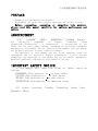
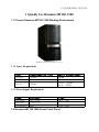
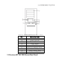
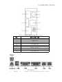
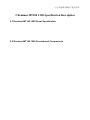
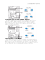
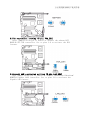
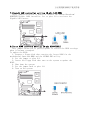
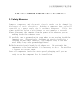
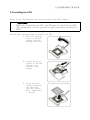
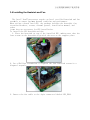
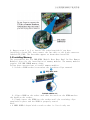
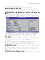
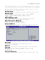
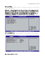
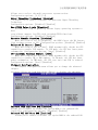
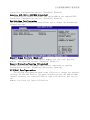
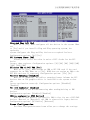
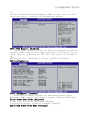
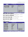
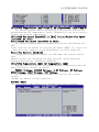
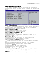
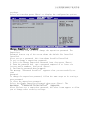
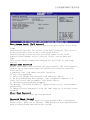
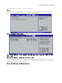
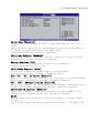
Founder Technology server user manual
—for Founder Reminus MT100 1200 ( V1.0 )
YM M T100 1200_101_000
方正科技服务器用户使用手册
PREFACE
Thank you for purchasing this product.
This manual can guide you to proper operation and correct setting.
Before connecting, operating or adjusting this product,
please read this manual carefully for optimum performance and
safety.
ANNOUNCEMENT
“方正”、“FOUNDER”、“圆明”、“圆明REMINUS”“FOUNDER
Reminus”
are
registered
trademarks
of
Founder
Technology
Group
Corporation(“Foundertech”) or Foundertech’ s associations in the
China. All the other names, brands, trademark or registered trademarks
mentioned in this manual are for identification purpose only and remain
the exclusive property of their respective owners.
The materials at this manual and any revise updating terms are
copyrighted and are protected. Without Foundertech’ s prior written
permission, any materials at this manual may not be copied, reproduced,
modified, published, transmitted, distributed in any way.
IMPORTANT SAFETY NOTICE
In the manual will show four kinds of safety notes as
follows:
DANGEROUS:This practice is
to your safety
CAUTION:This practice is
to your safety
NOTICE:This practice is
to your safety
INSTRUCTION:Description, for important notes
All rights reserved,
Shanghai, China.
Founder
Technology
Group
Corp.,
方正科技服务器用户使用手册
CONTENTS
1 QUICKLY USE REMINUS MT100 1200
1.1 Choose Reminus MT100 1200 Working Environment
1
1
1.1.1 Space Requirement
1
1.1.2 Power Supply Requirement
1
1.2 Reminus MT100 1200 Sever Front Panel
2
1.3 Reminus MT100 1200 Server Rear Panel
3
1.4 Operation System
4
2 REMINUS MT100 1200 SPECIFICATION DESCRIPTION
5
2.1 Reminus MT100 1200 Sever Specification
5
2.2 Reminus MT100 1200 Serverboard Components
6
2.3 Reminus MT100 1200 CPU Subsystem
7
2.4 Reminus MT100 1200 Memory Subsystem
7
2.5 Reminus MT100 1200 Storage Subsystem
8
2.6 Reminus MT100 1200 PCI、PCI-X Subsystem
8
2.7 Reminus MT100 1200 NIC Subsystem
8
2.8 Reminus MT100 1200 Power Supply Subsystem
8
2.9 Reminus MT100 1200 Jumper Description
8
3 REMINUS MT100 1200 HARDWARE INSTALLATION
3.1 Safety Measures
13
13
方正科技服务器用户使用手册
3.2 Serverboard Jumper Settings
3.2.1 Setting a Jumper
14
14
3.3 Installing the CPU
15
3.4 Installing the Heatsink and Fan
17
3.5 Installing Memory
18
3.6 Installing a PCI Card
19
4 REMINUS MT100 1200 FIRMWARE
20
4.1 Reminus MT100 1200 BIOS Configuration
20
4.1.1 Reminus MT100 1200 BIOS Settings
20
4.2 Reminus MT100 1200 SCSI RAID1 Settings
40
5 WINDOWS 2003 SERVER INSTALLATION
41
6 DRIVER CD USE GUIDE
42
方正科技服务器用户使用手册
方正科技服务器用户使用手册
1 Quickly Use Reminus MT100 1200
1.1 Choose Reminus MT100 1200 Working Environment
Reminus MT100 1200 Server
1.1.1 Space Requirement
Spec
Height
Width
ReminusMT100 1200
555mm
226mm
Depth
493mm
Space requirement
100mm
100mm
front:300mm
back:200mm
1.1.2 Power Supply Requirement
Spec
Voltage
Current
Frequency
Standard
110V-220V
7.5A-3.5A
50Hz
Limit
200V~230V
47Hz~63Hz
1.2 Reminus MT100 1200 Sever Front Panel
方正科技服务器用户使用手册
Reminus MT100 1200 Server Front Panel
No.
A
B
C
D
E
F
G
H
I
Description
5.25 inch Bays
Power Button
Reset Button
Alert Reset
HDD LED
Lock of Chassis Door
3.5 inch Bays
Front Panel Lock
Power LED
1.3 Reminus MT100 1200 Server Rear Panel
方正科技服务器用户使用手册
Reminus MT100 1200 Server Rear Panel
No.
A
B
C
D
E
F
G
H
Description
Bolt
HDD Fan
Bolt
System Fan
NC
Power Supply
I/O Port
PCI Baffle
IO ports
1
Mouse
2
Connect a PS/2 pointing device to this
方正科技服务器用户使用手册
3
4
9
Keyboa
rd
USB
LAN
Port
COM
11
VGA
12
13
LAN
14
5
7
6
8
10
port.
Connect a PS/2 keyboard to this port.
Use the USB ports to connect USB devices.
10 Mbps RJ-45 LAN port (for optional BMC
card)
Use the serial port COM1 to connect serial
devices such as mice or fax/modems.
Use the VGA port to connect an external
monitor.
10/100/1000 Mbps RJ-45 LAN port (for
onboard LAN chipset)
1.4 Operation System
Reminus MT100 1200 server support OS:
Windows 2003
Windows 2003
Red Hat Linux 9.0
CPU
L2 cache
FSB
Memory
Chipset
SCSI
RAID
VGA
CDROM
Floppy
PCI
Storage
NIC
Cooler
Keyboard
Mouse
P o w e r
Supply
Support dual Intel XEON 2.8GHz-3. 6GHz processors
1M/2M L2 cache
800MHz
ECC Registered DDR2-400 memory;
Six DIMM,up to 6/24GB memory;
Chipkill;
Intel E7320
Dual channel SCSI controller, integrated RAID1
function;(optional)
Ultra320 SCSI RAID; (optional)
ATI Rage XL VGA;
8MB SDRAM;
5.25 inch IDE CDROM
3.5 inch 1.44MB floppy
Five PCI slots
Four 5.25 inch device storage bay;
Two 3.5 inch device storage bay;
Five 3.5 inch device storage bay;
Broadcom5705, Broadcom5721
Two system coolers;
PS/2 interface
PS/2 interface
460W power supply, 400W 1+1 hot plug redundant power
supply optional;
方正科技服务器用户使用手册
2 Reminus MT100 1200 Specification Description
2.1 Reminus MT100 1200 Sever Specification
2.2 Reminus MT100 1200 Serverboard Components
方正科技服务器用户使用手册
15
17
19
Label
CPU1/2
DDR2
DDR_A1/B1
,A2/B2,
A3/B3
16
Component
18
604-pin CPU socket
DDR2 DIMM sockets
CLRTC1
FM_CPU1, FM_CPU2
Clear RTC RAM
CPU fan pin selection
USBPW12, USBPW34
USB device wake-up
20
Keyboard power
VGA controller setting
Gigabit LAN controller setting
Force BIOS recovery setting
KBPWR1
VGA_EN1
LAN_EN1/2
RECOVERY1
方正科技服务器用户使用手册
FLOPPY1
PRI_IDE, SEC_IDE
Floppy disk drive connector
Primary IDE connectors
SATA1, SATA2
HDLED1
USB34
COM2
CPU_FAN1/2,
REAR_FAN1/2,
FRNT_FAN1/2
BMCCONN1
BPSMB1
PSUSMB1
ATXPWR1, 8-pin
ATX12V1
PANEL1
AUX_PANEL1
Serial ATA connectors
Hard disk activity LED connector
USB connector
Serial port connector
CPU and system fan connectors
BMC connector
Backplane SMBus connector
Power supply SMBus connector
ATX power connectors
System panel connector
Auxiliary panel connector
2.3 Reminus MT100 1200 CPU Subsystem
Reminus MT100 1200 support dual Intel XEON processors.
Support 800MHz FSB,support Hyper-threading.
2.4 Reminus MT100 1200 Memory Subsystem
Reminus MT100 1200
REG DDR2 400 memory.
integrate six DDR DIMMs,support up to 24G ECC
2.5 Reminus MT100 1200 Storage Subsystem
Storage device interface:
Two ATA100 IDE interface;
One floppy interface;
Two Ultra320 SCSI interface(optional);
2.6 Reminus MT100 1200 PCI、PCI-X Subsystem
One x4 PCI-E ;
Two 64bit/66MHz PCI;
Two 32bit/33MHz的PCI;
2.7 Reminus MT100 1200 NIC Subsystem
Two 100M/1000 NIC;
2.8 Reminus MT100 1200 Power Supply Subsystem
One 460W power supply;
400W 1+1 hot plug redundant power supply optional;
方正科技服务器用户使用手册
2.9 Reminus MT100 1200 Jumper Description
1.Clear RTC RAM (CLRTC1):
This jumper allows you to clear the Real Time Clock (RTC) RAM in
CMOS. You can clear the CMOS memory of date, time, and system
setup parameters by erasing the CMOS RTC RAM data. The onboard
button cell battery powers the RAM data in CMOS, which include
system setup information such as system passwords.
To erase the RTC RAM:
1. Turn OFF the computer and unplug the power cord.
2. Remove the onboard battery.
3. Move the jumper cap from pins 1-2 (default) to pins 2-3. Keep the
cap on pins 2-3 for about 5~10 seconds, then move the cap back
to pins 1-2.
4. Re-install the battery.
5. Plug the power cord and turn ON the computer.
6. Hold down the <Del> key during the boot process and enter BIOS setup
to re-enter data.
2 .CPU
These
plug to
jumpers
fan pin selection (3-pin FM_CPU1, FM_CPU2)
jumpers allow you to connect either a 3-pin or a 4-pin fan cable
the CPU fan connectors (CPU_FAN1, CPU_FAN2). Set these
to pins 1-2 if you are using a 3-pin fan cable plug, or to pins
2-3 if you are using a 4-pin plug.
方正科技服务器用户使用手册
3.USB device wake-up (3-pin USBPW12, USBPW34)
Set these jumpers to +5V to wake up the computer from S1 sleep
mode (CPU stopped, DRAM refreshed, system running in low power
mode) using the connected USB devices. Set to +5VSB to wake up
from S4 sleep mode (no power to CPU, DRAM in slow refresh, power
supply in reduced power mode).
4.Keyboard power (3-pin KBPWR1)
This jumper allows you to enable or disable the keyboard wake-up
feature. Set this jumper to pins 2-3 (+5VSB) to wake up the computer
when you press a key on the keyboard (the default is the Space Bar).
This feature requires an ATX power supply that can supply at least 1A
on the +5VSB lead, and a corresponding setting in the BIOS.
方正科技服务器用户使用手册
5.VGA controller setting (3-pin VGA_EN1)
These jumpers allow you to enable or disable the onboard ATI
RAGE-XL PCI VGA controller. Set to pins 1-2 to activate the VGA
feature.
6.Gigabit LAN controller setting (3-pin LAN_EN1)
This jumper allows you to enable or disable the onboard Broadcom®
BCM5721 Gigabit LAN1 controller. Set to pins 1-2 to activate the
Gigabit LAN feature.
方正科技服务器用户使用手册
7.Gigabit LAN controller setting (3-pin LAN_EN2)
These jumpers allow you to enable or disable the onboard Broadcom®
BCM5705E Gigabit LAN2 controller. Set to pins 1-2 to activate the
Gigabit LAN feature.
8.Force BIOS recovery setting (3-pin RECOVERY1)
This jumper allows you to quickly update or recover the BIOS settings
when it becomes corrupted.
To update the BIOS:
1. Prepare a floppy disk that contains the latest BIOS for the
motherboard (xxxx-xxx.ROM) and the AFUDOS.EXE utility.
2. Set the jumper to pins 2-3.
3. Insert the floppy disk then turn on the system to update the
BIOS.
4. Shut down the system.
5. Set the jumper back to pins 1-2.
6. Turn on the system.
方正科技服务器用户使用手册
3 Reminus MT100 1200 Hardware Installation
3.1 Safety Measures
Computer components and electronic circuit boards can be damaged by
discharges of static electricity. Working on computers that are still
connected to a power supply can be extremely dangerous.
Follow the
simple guidelines below to avoid damage to your computer or yourself.
Always disconnect the computer from the power outlet whenever you are
working inside the computer case.
If possible, wear a grounded wrist strap when you are working inside the
computer case. Alternatively, discharge any static electricity by
touching the bare metal chassis of the computer case, or the bare
metal body of any other grounded appliance.
Hold electronic circuit boards by the edges only. Do not touch the
components on the board unless it is necessary to do so. Do not flex
or stress the circuit board.
Leave all components inside the static-proof packaging until you are
ready to use the component for the installation.
方正科技服务器用户使用手册
方正科技服务器用户使用手册
3.2 Serverboard Jumper Settings
Refer to this section when setting the jumpers on the serverboard.
3.2.1 Setting a Jumper
The serverboard jumpers are to set system configuration options. When
setting jumpers, ensure the shunts (jumper caps) are placed on the
correct pins.
1
This 2-pin jumper is
ON/SHORT.
This 2-pin jumper is
OFF/OPEN.
Pins 1 and 2 are ON/SHORT
on this 3-pin jumper.
方正科技服务器用户使用手册
方正科技服务器用户使用手册
3.3 Installing the CPU
Refer to the illustration for the location of the CPU sockets.
1
Important!
When only installing one CPU, the CPU must be installed in CPU1.
The system will not boot up with a single processor installed in
CPU2.
Follow these instructions to install the CPU:
1. Pull the locking
lever of the CPU
socket into the
upright position.
2. Locate the pin-1
corner of the CPU
and the pin-1
corner of the
socket.
3. Align the pin-1
corners and drop
the processor
into the socket.
(See “Important!
” below.)
方正科技服务器用户使用手册
4. Swing the locking
lever back down
to lock the
processor in
place.
2
Important!
The mPGA604, 604-pin socket is a ZIF socket (Zero Insertion Force
socket). This type of socket is designed for easy insertion of the
CPU. The chip is easily dropped into the socket, and the lever is
pulled down to lock it in. If any resistance is noticed when
inserting the CPU, check that it is aligned correctly.
方正科技服务器用户使用手册
方正科技服务器用户使用手册
3.4 Installing the Heatsink and Fan
The Intel® Xeon™ processors require an Intel certified heatsink and fan
assembly to ensure optimum thermal condition and performance.
When you buy a boxed Intel CPU, the package includes the heatsink, fan,
retention brackets, screws, thermal grease, installation manual, and
other
items that are necessary for CPU installation.
To install the CPU heatsink and fan:
1. Place the heatsink on top of the installed CPU, making sure that the
four screws on the heatsink align with the nuts on the support plate.
2. Use a Phillips screwdriver to tighten the four heatsink screws in a
diagonal sequence.
3. Connect the fan cable to the 4-pin connector labeled CPU_FAN1.
方正科技服务器用户使用手册
4. Repeat steps 1 to 3 to install the other heatsink if you have
installed a second CPU, then connect the fan cable to the 4-pin connector
labeled CPU_FAN2. The heatsinks appear as shown when installed.
3.5 Installing Memory
The serverboard has Six DDR-DIMM (Double Data Rate Dual In-line Memory
Modules) slots for the installation of memory modules. The memory modules
require 1.8V DDR SDRAM memory chips.
Follow these instructions to install memory modules:
1. Unlock a DIMM socket by pressing the retaining clips outward.
2. Align a DIMM on the socket such that the notch on the DIMM matches
the break on the socket.
3. Firmly insert the DIMM into the socket until the retaining clips
snap back in place and the DIMM is properly seated.
Note:
• A DDR2 DIMM is keyed with a notch so that it fits in only one
方正科技服务器用户使用手册
direction. Do not force a DIMM into a socket to avoid damaging the DIMM.
• The DDR2 DIMM sockets do not support DDR DIMMs. DO NOT install DDR
DIMMs to the DDR2 DIMM sockets.
3.6 Installing a PCI Card
Refer to the illustration for the location of the PCI slots.
Follow these instructions to install a PCI card:
1. Remove a blanking plate from the system case.
2. Install the PCI card into the expansion slot.
3.
Secure the metal bracket of the PCI card to the system case with a
screw.
This concludes the second chapter. The next chapter covers the
BIOS setup utility.
4 Reminus MT100 1200 Firmware
4.1 Reminus MT100 1200 BIOS Configuration
4.1.1 Reminus MT100 1200 BIOS Settings
方正科技服务器用户使用手册
Setup Menu
The computer employs the latest AMI BIOS CMOS chip with support for
Windows Plug and Play. This CMOS chip contains the ROM Setup instructions
for configuring the mainboard’s BIOS. The BIOS (Basic Input and Output
System) Setup utility is a menu driven utility that enables you to make
changes to the system configuration and tailor your system to suit your
individual work needs. BIOS is a ROM-based configuration utility that
displays the system’s configuration status and provides you with a tool
to set system parameters. These parameters are stored in non-volatile
battery-backed-up CMOS RAM that saves this information even when the
power is turned off. When the system is turned back on, the system is
configured with the values found in CMOS.
Configure such items as:
Hard drives, diskette drives, and peripherals
Password protection from unauthorized use
Power Management features
This Setup utility should be executed under the following conditions:
When changing the system configuration
When a configuration error is detected by the system and you are prompted
to make changes to the Setup utility
When redefining the communication ports to prevent any conflicts
When making changes to the Power Management configuration
When changing the password or making other changes to the security setup
3
Note:
Only items in brackets [ ] can be modified. Items that
are not in brackets are display only.
BIOS Setup Options at Boot
The user will be able to initiate SETUP by pressing the respective keys.
<DEL>
Enter the BIOS Setup
Main Menu
When you enter the BIOS Setup program, the Main menu screen appears,
giving you an overview of the basic system information.
方正科技服务器用户使用手册
System Time [xx:xx:xx]
Allows you to set the system time.
System Date [Day xx/xx/xxxx]
Allows you to set the system date.
Legacy Diskette A [1.44M, 3.5 in.]
Sets the type of floppy drive installed. Configuration options:
[Disabled]
[360K, 5.25 in.] [1.2M , 5.25 in.] [720K , 3.5 in.] [1.44M, 3.5 in.] [2.
88M, 3.5 in.]
IDE Configuration
The items in this menu allow you to set or change the configurations for
the IDE devices installed in the system. Select an item then press
<Enter>
if you wish to configure the item.
Onboard IDE Operate Mode [Enhanced Mode]
Allows selection of the IDE operation mode depending on the installed
operating system (OS). Set to [Enhanced Mode] if you are using native OS,
e.g. Windows® 2000/XP. Set to [Compatible Mode] if you are using legacy
方正科技服务器用户使用手册
OS, e.g. Windows ME/98/NT, MS-DOS.
Configuration options: [Compatible Mode] [Enhanced Mode]
IDE Detect Time Out (Sec) [35]
Selects the time our value (in seconds) for detecting ATA/ATAPI
devices.
Configuration options: [0] [5] [10] [15] [20] [25] [30] [35]
Primary/Secondary IDE Master/Slave, Tertiary and Fourth IDE
Master
The BIOS automatically detects the connected IDE devices. There is a
separate sub-menu for each IDE device. Select a device item, then press
<Enter> to display the IDE device information.
The BIOS automatically detects the values opposite the dimmed items
(Device, Vendor, Size, LBA Mode, Block Mode, PIO Mode, Async DMA, Ultra
DMA, and SMART monitoring). These values are not user-configurable.
These items show N/A if no IDE device is installed in the system.
Type [Auto]
Selects the type of IDE drive. Setting to [Auto] allows automatic
selection
of the appropriate IDE device type. Select [CDROM] if you are
specifically
configuring a CD-ROM drive. Select [ARMD] (ATAPI Removable Media
Device) if your device is either a ZIP, LS-120, or MO drive.
Configuration options: [Not Installed] [Auto] [CDROM] [ARMD]
LBA/Large Mode [Auto]
Enables or disables the LBA mode. Setting to [Auto] enables the LBA
mode
if the device supports this mode, and if the device was not previously
formatted with LBA mode disabled. Configuration options: [Disabled]
[Auto]
Block (Multi-sector Transfer) [Auto]
Enables or disables data multi-sectors transfers. When set to [Auto],
the
方正科技服务器用户使用手册
data transfer from and to the device occurs multiple sectors at a time if
the device supports multi-sector transfer feature. When set to [Disabled]
,
the data transfer from and to the device occurs one sector at a time.
Configuration options: [Disabled] [Auto]
PIO Mode [Auto]
Selects the PIO mode. Configuration options: [Auto] [0] [1] [2] [3] [4]
DMA Mode [Auto]
Selects the DMA mode. Configuration options: [Auto] [SWDMA0]
[SWDMA1] [SWDMA2] [MWDMA0] [MWDMA1] [MWDMA2] [UDMA0]
[UDMA1] [UDMA2]
SMART Monitoring [Auto]
Sets the Smart Monitoring, Analysis, and Reporting Technology.
Configuration options: [Auto] [Disabled] [Enabled]
32Bit Data Transfer [Disabled]
Enables or disables 32-bit data transfer.
Configuration options: [Disabled] [Enabled]
System Information
This menu gives you an overview of the general system specifications.
The BIOS automatically detects the items in this menu.
Model Name
Displays the auto-detected ASUS motherboard model (either
NCLV-D2/SATA, or NCLV-DS2).
Model ID
Displays the auto-detected identification number of the motherboard.
ASUS BIOS
Displays the auto-detected BIOS version in the
motherboard.
Processor Information
Displays the auto-detected information about the installed CPU or CPUs.
方正科技服务器用户使用手册
System Memory Information
Displays the auto-detected information about the installed DDR2 DIMMs.
方正科技服务器用户使用手册
Advanced Menu
The Advanced menu items allow you to change the settings for the CPU and
other system devices.
Warning!
Making incorrect settings to items on these pages may cause
the system to malfunction. Unless you have experience adjusting these
items, we recommend that you leave these settings at the default values.
If making settings to items on these pages causes your system to
malfunction or prevents the system from booting, open BIOS and choose
“Load Optimal Defaults” in the Exit menu to boot up normally.
CPU Configuration
The items in this menu show the CPU-related information that the BIOS
automatically detects.
MPS Table Version [1.4]
方正科技服务器用户使用手册
Allows you to select the multi-processor system version.
Configuration options: [1.1] [1.4]
Hyper Threading Technology [Enabled]
Allows you to enable or disable the processor Hyper-Threading
Technology.
Configuration options: [Disabled] [Enabled]
Max CPUID Value Limit [Disabled]
Setting this item to [Enabled] allows legacy operating systems to
boot
even without support for CPUs with extended CPUID functions.
Configuration options: [Disabled] [Enabled]
Execute Disable Function [Disabled]
When this item is set to [Disabled], the BIOS forces the XD feature
flag toalways return to (0). Configuration options: [Disabled] [Enabled]
Enhanced C1 Control [Auto]
When this item is set to [Auto], BIOS automatically checks the CPU
capability to enable C1E support. In C1E mode, the CPU has lower power
consumption. Configuration options: [Auto] [Disabled]
CPU Internal Thermal Control [Auto]
When this item is set to [Auto], BIOS automatically checks the CPU
capability to enable TM or TM2 support. In TM mode, the CPU has lower
power consumption. In TM2 mode, the CPU core ratio and VID is reduced.
Configuration options: [Auto] [Disabled]
Chipset Configuration
The Chipset Configuration menu allows you to change the advanced
chipset
settings. Select an item then press <Enter> to display the sub-menu.
Onboard PCIE LAN Boot ROM [Enabled]
Allows you to enable or disable the option ROM in the onboard LAN
controller. Configuration options: [Disabled] [Enabled]
Onboard PCI LAN Boot ROM [Enabled]
Allows you to enable or disable the option ROM in the onboard LAN
方正科技服务器用户使用手册
controller. Configuration options: [Disabled] [Enabled]
Adaptec AIC-7901x BOOTROM [Enabled]
Allows you to enable or disable the option ROM in the onboard SCSI
controller. Configuration options: [Disabled] [Enabled]
NorthBridge Configuration
The NorthBridge Configuration menu allows you to change the Northbridge
related settings.
Memory Remap Feature [Enabled]
Allows you to remap the overlap PCI memory over the total physical
memory. Configuration options: [Disabled] [Enabled]
Memory Mirroring/Sparing [Disabled]
Allows you to select the memory RAS feature: mirroring or sparing.
Configuration options: [Disabled] [Mirroring] [Sparing]
PCI/PnP Configuration
The PCI/PnP Configuration menu items allow you to change the advanced
settings for PCI/PnP devices. The menu includes setting the IRQ and DMA
channel resources for either PCI/PnP or legacy ISA devices, and setting
the
memory size block for legacy ISA devices.
方正科技服务器用户使用手册
Plug And Play O/S [No]
When set to [No], BIOS configures all the devices in the system. When
set
to [Yes] and if you install a Plug and Play operating system, the
operating
system configures the Plug and Play devices not required for boot.
Configuration options: [No] [Yes]
PCI Latency Timer [64]
Allows you to select the value in units of PCI clocks for the PCI
device
latency timer register. Configuration options: [32] [64] [96] [128] [160]
[192] [224] [248]
Allocate IRQ to PCI VGA [Yes]
When set to [Yes], BIOS assigns an IRQ to PCI VGA card if the card
requests for an IRQ. When set to [No], BIOS does not assign an IRQ to the
PCI VGA card even if requested. Configuration options: [Yes] [No]
Palette Snooping [Disabled]
When set to [Enabled], the pallete snooping feature informs the PCI
devices that an ISA graphics device is installed in the system so that
the
latter can function correctly. Configuration options: [Disabled]
[Enabled]
PCI IDE BusMaster [Enabled]
Allows BIOS to use PCI bus mastering when reading/writing to IDE
devices.
Configuration options: [Disabled] [Enabled]
IRQ-xx assigned to [PCI Device]
When set to [PCI Device], the specific IRQ is free for use of PCI/PnP
devices. When set to [Reserved], the IRQ is reserved for legacy devices.
Configuration options: [PCI Device] [Reserved]
Power Configuration
The Power Configuration menu items allow you to change the settings
方正科技服务器用户使用手册
for
the ACPI and Advanced Power Management (APM) features. Select an item
then press <Enter> to display the configuration options.
ACPI APIC Support [Enabled]
Allows you to enable or disable the Advanced Configuration and Power
Interface (ACPI) support in the Application-Specific Integrated Circuit
(ASIC). When set to Enabled, the ACPI APIC table pointer is included in
the
RSDT pointer list. Configuration options: [Disabled] [Enabled]
APM Configuration
Power Management [Enabled]
Allows you to enable or disable the motherboard Advance Power
Management (APM) feature. Configuration options: [Enabled] [Disabled]
Video Power Down Mode [Suspend]
Allows you to select the video power down mode
Configuration options: [Disabled] [Standby] [Suspend]
Hard Disk Power Down Mode [Suspend]
方正科技服务器用户使用手册
Allows you to select the hard disk power down mode
Configuration options: [Disabled] [Standby] [Suspend]
Suspend Time Out (Minute) [Disabled]
Allows you to select the specified time at which the system goes on
suspend mode. Configuration options: [Disabled] [1 Min] [2 Min] [4 Min]
[8 Min] [10 Min] [20 Min] [30 Min] [40 Min] [50 Min] [60 Min]
Throttle Slow Clock Ratio [50%]
Allows you to select duty cycle in throttle mode.
Configuration options: [87.5%] [75.0%] [62.5%] [50.0%] [37.5%]
[25.0%] [12.5%]
Power Button Mode [On/Off]
Allows the system to go into On/Off mode or suspend mode when the
power button is pressed. Configuration options: [On/Off] [Suspend]
Restore on AC Power Loss [Power Off]
When set to Power Off, the system goes into off state after an AC
power
loss. When set to Power On, the system goes on after an AC power loss.
When set to Last State, the system goes into either off or on state,
whatever the system state was before the AC power loss.
Configuration options: [Power Off] [Power On] [Last State]
Power On By PS/2 Keyboard [Disabled]
Allows you to use specific keys on the keyboard to turn on the
system.
This feature requires an ATX power supply that provides at least 1A on
the
+5VSB lead. Configuration options: [Disabled] [Enabled]
Power On By PS/2 Mouse [Disabled]
When set to [Enabled], this parameter allows you to use the PS/2
mouse
to turn on the system. This feature requires an ATX power supply that
provides at least 1A on the +5VSB lead. Configuration options: [Disabled]
[Enabled]
Power On Ring [Disabled]
When set to [Enabled], the system enables the RI to generate a wake
event while the computer is in Soft-off mode.
Configuration options: [Disabled] [Enabled]
Power On By PME# [Disabled]
When set to [Enabled], the system enables the PME to generate a wake
event while the computer is in Soft-off mode.
Configuration options: [Disabled] [Enabled]
Power On By RTC Alarm [Disabled]
Allows you to enable or disable RTC to generate a wake event. When
this
item is set to [Enabled], the items RTC Alarm Date, RTC Alarm Hour, RTC
Alarm Minute, and RTC Alarm Second appear with set values.
Configuration options: [Disabled] [Enabled]
USB Configuration
方正科技服务器用户使用手册
The items in this menu allows you to change the USB-related features.
Select an item then press <Enter> to display the configuration options.
USB Function [All USB Ports]
Allows you to enable a specific number of USB ports, or disable the
USB
function. Configuration options: [Disabled] [2 USB Ports] [All USB Ports]
Legacy USB Support [Auto]
Allows you to enable or disable support for legacy USB devices.
Setting to[Auto] allows the system to detect the presence of legacy USB
devices at
startup. If detected, the USB controller legacy mode is enabled. If no
legacy
USB device is detected, the legacy USB support is disabled.
Configuration options: [Disabled] [Enabled] [Auto]
USB 2.0 Controller [Enabled]
Allows you to enable or disable the USB 2.0 controller.
Configuration options: [Enabled] [Disabled]
USB 2.0 Controller Mode [HiSpeed]
Allows you to set the USB 2.0 controller mode to HiSpeed (480 Mbps)
or
FullSpeed (12 Mbps). Configuration options: [FullSpeed ] [HiSpeed]
Super IO Configuration
方正科技服务器用户使用手册
Serial Port1 Address [3F8/IRQ4]
Allows you to select the Serial Port1 base address.
Configuration options: [Disabled] [3F8/IRQ4] [3E8/IRQ4] [2E8/IRQ3]
Serial Port2 Address [2F8/IRQ3]
Allows you to select the Serial Port2 base address.
Configuration options: [Disabled] [2F8/IRQ3] [3E8/IRQ4] [2E8/IRQ3]
Parallel Port Address [378]
Allows you to select the Parallel Port base addresses.
Configuration options: [Disabled] [378] [278] [3BC]
Parallel Port Mode [Normal]
Allows you to select the Parallel Port mode. Configuration options:
[Normal]
[Bi-Directional] [EPP] [ECP]
Hardware Monitor
Use the down arrow key to display additional items.
方正科技服务器用户使用手册
CPU1/CPU2 Temperature [xxxºC/xxxºF] MB Temperature [xxxºC/xxxºF]
The onboard hardware monitor automatically detects and displays the
motherboard and CPU temperatures. Select [Disabled] if you do not wish to
display the detected temperatures.
CPU1/CPU2 Fan Speed [xxxxRPM] or [N/A] Front1/Front2 Fan Speed
[xxxxRPM] or [N/A]
Rear1/Rear2 Fan Speed [xxxxRPM] or [N/A]
The onboard hardware monitor automatically detects and displays the
CPU,
front, and rear fan speeds in rotations per minute (RPM). If a fan is not
connected to the connector on the motherboard, the field shows N/A.
Smart Fan Control [Enabled]
Allows you to enable or disable the ASUS Smart Fan Control feature
that
smartly adjusts the fan speeds for more efficient system operation.
Configuration options: [Disabled] [Enabled]
CPU1/CPU2 Temperature [XXX] MB Temperature [XXX]
Displays the detected CPU and system threshold temperatures when the
Smart Fan Control feature is enabled.
VCORE1 Voltage, VCORE2 Voltage, 3.3V Voltage, 5V Voltage,
5VSB Voltage, VBAT Voltage, 12V Voltage
The onboard hardware monitor automatically detects the voltage
outputs
through the onboard voltage regulators.
Server menu
The Server menu items allow you to customize the server features.
方正科技服务器用户使用手册
Remote Access Configuration
The items in this menu allows you to configure the Remote Access
features. Select an item then press <Enter> to display the configuration
options.
Remote Access [Enabled]
Enables or disables the remote access feature. Setting this item to
[Enabled] displays other connectivity items (see the screen below).
Configuration options: [Disabled] [Enabled]
Serial port number [COM1]
Enables or disables the remote access feature.
Configuration options: [Disabled] [Enabled]
Serial Port Mode [115200 8,n,1]
Sets the Serial port mode.
Configuration options: [115200 8,n,1] [57600 8,n,1] [38400 8,n,1]
[19200 8,n,1] [09600 8,n,1]
Flow Control [None]
Allows you to select the flow control for console redirection.
Configuration options: [None] [Hardware] [Software]
Redirection After BIOS POST [Always]
Sets the redirection mode after the BIOS Power-On Self-Test (POST).
Some
operating systems may not work when this item is set to Always.
Configuration options: [Disabled] [Boot Loader] [Always]
Terminal Type [ANSI]
Allows you to select the target terminal type.
Configuration options: [ANSI] [VT100] [VT-UTF8]
VT-UTF8 Combo Key Support [Disabled]
Enables or disables the VT-UTF8 combo key support for ANSI or VT100
terminals. Configuration options: [Disabled] [Enabled]
Security
The Security menu items allow you to change the system security
方正科技服务器用户使用手册
settings.
Select an item then press <Enter> to display the configuration options.
Change Supervisor Password
Select this item to set or change the supervisor password. The
Supervisor
Password item on top of the screen shows the default Not Installed
Installed.
After you set a password, this item shows Installed Installed.
To set or change a supervisor password:
1. Select the Change Supervisor Password item, then press <Enter>.
2. From the password box, type a password composed of at least six
letters and/or numbers, then press <Enter>.
3. Confirm the password when prompted.
The message “Password Installed” appears after you successfully set
your
password.
To change the supervisor password, follow the same steps as in setting a
user password.
To clear the supervisor password:
Select the Change Supervisor Password then press <Enter>. The
message “Password Uninstalled” appears.
After you have set a supervisor password, the other items appear to allow
you to change other security settings.
方正科技服务器用户使用手册
User Access Level [Full Access]
This item allows you to select the access restriction to the Setup
items.
Configuration options: [No Access] [View Only] [Limited] [Full Access]
No Access prevents user access to the Setup utility.
View Only allows access but does not allow change to any field.
Limited allows changes only to selected fields, such as Date and
Time.
Full Access allows viewing and changing all the fields in the Setup
utility.
Change User Password
Select this item to set or change the user password. The User Password
item on top of the screen shows the default Not Installed Installed.
After you set
a password, this item shows Installed Installed.
To set a user password:
1. Select the Change User Password item and press <Enter>.
2. On the password box that appears, type a password composed of at
least six letters and/or numbers, then press <Enter>.
3. Confirm the password when prompted.
The message “Password Installed” appears after you set your password
successfully.
To change the user password, follow the same steps as in setting a user
password.
Clear User Password
Select this item to clear the user password.
Password Check [Setup]
When set to [Setup], BIOS checks for user password when accessing the
Setup utility. When set to [Always], BIOS checks for user password both
when accessing Setup and booting the system.
方正科技服务器用户使用手册
Configuration options: [Setup] [Always]
Boot
The Boot menu items allow you to change the system boot options. Select
an item then press <Enter> to display the sub-menu.
Boot Device Priority
1st Boot Device [1st FLOPPY DRIVE] 2nd Boot Device [MBA v7.6.6
Slot 02]
3rd Boot Device [MBA v7.6.6 Slot 04]
These items specify the boot device priority sequence from the available
devices. Configuration options: [1st FLOPPY DRIVE] [MBA v7.6.6 Slot 02]
[MBA v7.6.6 Slot 04] [Disabled]
Boot Settings Configuration
方正科技服务器用户使用手册
Quick Boot [Enabled]
Enabling this item allows the BIOS to skip some power on self tests
(POST)
while booting to decrease the time needed to boot the system. When set
to [Disabled], BIOS performs all the POST items.
Configuration options: [Disabled] [Enabled]
Full Logo display [Enabled]
Allows you to enable or disable the full screen logo display feature.
Configuration options: [Disabled] [Enabled]
Bootup Num-Lock [On]
Allows you to select the power-on state for the NumLock.
Configuration options: [Off] [On]
PS/2 Mouse Support [Auto]
Allows you to enable or disable support for PS/2 mouse.
Configuration options: [Disabled] [Enabled] [Auto]
Wait for ‘F1’ If Error [Enabled]
When set to Enabled, the system waits for the F1 key to be pressed when
error occurs. Configuration options: [Disabled] [Enabled]
Hit ‘DEL’ Message Display [Enabled]
When set to Enabled, the system displays the message “Press DEL to run
Setup” during POST. Configuration options: [Disabled] [Enabled]
Interrupt 19 Capture [Enabled]
When set to [Enabled], this function allows the option ROMs to trap
Interrupt 19. Configuration options: [Disabled] [Enabled]
Exit
The Exit menu items allow you to load the optimal or failsafe default
values
for the BIOS items, and save or discard your changes to the BIOS items.
方正科技服务器用户使用手册
Exit & Save Changes
Select this option then press <Enter>, or simply press <F10>, to save
your
changes to CMOS before exiting the Setup utility.
When a confirmation window appears, select [OK] then press <Enter> to
save your changes and exit Setup. If you wish to cancel the command,
select [Cancel] then press <Enter> to return to the Exit menu.
Exit & Discard Changes
Select this option then press <Enter> to exit the Setup utility without
saving your changes.
When a confirmation window appears, select [OK] then press <Enter> to
discard your changes and exit Setup. If you wish to cancel the command,
select [Cancel] then press <Enter> to return to the Exit menu.
Discard Changes
Select this option then press <Enter> to discard the changes that you
made, and restore the previously saved settings.
When a confirmation window appears, select [OK] then press <Enter> to
discard the changes, and load the previously saved settings. If you wish
to
cancel the command, select [Cancel] then press <Enter> to return to the
Exit menu.
Load Setup Defaults
Select this option then press <Enter> to load the optimized settings for
each of the Setup menu items.
When a confirmation window appears, select [OK] then press <Enter> to
load the default settings. If you wish to cancel the command, select
[Cancel] then press <Enter> to return to the Exit menu.
方正科技服务器用户使用手册
4.2 Reminus MT100 1200 SCSI RAID1 Settings
Power on, when screen display:
Press Ctrl-C to start LSI Logic Configuration Utility...
Press Ctrl-C to run SCSI RAID1 settings;
Press ENTER, system will scan SCSI devices;
Chose Mirroring Properties, after press ENTER system will display hard
disks information;
If you have two hard disks, use +/- key set two hard disks to Primary
and Secondary, save and exit;
If you have three hard disks, you may set the third hard disk to HOT
Spare.
5 Windows 2003 Server Installation
1、Boot
Put Windows 2003 Server CD into the CD-ROM, power on and set the
system boot from CD-ROM;
方正科技服务器用户使用手册
2、[Setup is Inspect your hardware……], and press F6;
a、[To specify additional SCSI adapters, CD-ROM drivers,
or special disk controllers for use with Windows 2003 ……],
press S
b、[Please insert the disk labeled Manufacturer-supplied
hardware support disk into Drive A:], press ENTER
Choose [LSI Logic PCI SCSI/FC MPI Miniport Driver], press
ENTER
3、[To set up Windows 2003 now], press ENTER
4、[Windows 2003 Licensing Agreement], press F8
5、[The following list shows the existing partitions and
unpartitioned space on this computer],Press C to create a partition
in the unpartitioned space
6、[To create the new partition, enter a size below and
press ENTER]
7、[C: New <Unformatted> xxxxMB], press ENTER
8、[Format the partition using the NTFS file system], press
ENTER
9、[Welcome to Windows 2003 setup wizard], press next
10、[Regional settings],you can customize Windows 2003 for
different regions and languages, choose next
11、[Personalize your software], type your full name and the name
of your company or organization.
12、[Your product License]
13、[Licensing Modes], select the licensing mode you want to use
14、[Computer name and administrator password]
15、[Windows 2003 components], you can add or remove components
of windows 2003
16、[Date and Time Settings], set the correct date and time for
your Windows computer
17、[You have already finished the installation of Windows
2003 Server]
6 Driver CD Use Guide
Chipset:
NIC driver:
SCSI driver:
SATA RAID
方正圆明服务器资源光盘V1.53:\CHIPSET\ intel_chipset
方正圆明服务器资源光盘V1.53:\lan\Bcm570x
方正圆明服务器资源光盘V1.53:\ scsi\ Lsi
方正圆明服务器资源光盘V1.53:\RAID\6300ESB\6300ESB