1
Agilent Technologies
3458A Multimeter
User’s Guide
Manual Part Number: 03458-90014
Printed in U.S.A
AGILENT TECHNOLOGIES WARRANTY STATEMENT
AGILENT PRODUCT: 3458A Multimeter
DURATION OF WARRANTY: 1 year
1. Agilent Technologies warrants Agilent hardware, accessories and supplies against defects in materials and workmanship for the period
specified above. If Agilent receives notice of such defects during the warranty period, Agilent will, at its option, either repair or replace
products which prove to be defective. Replacement products may be either new or like-new.
2. Agilent warrants that Agilent software will not fail to execute its programming instructions, for the period specified above, due to
defects in material and workmanship when properly installed and used. If Agilent receives notice of such defects during the warranty
period, Agilent will replace software media which does not execute its programming instructions due to such defects.
3. Agilent does not warrant that the operation of Agilent products will be interrupted or error free. If Agilent is unable, within a reasonable
time, to repair or replace any product to a condition as warranted, customer will be entitled to a refund of the purchase price upon prompt
return of the product.
4. Agilent products may contain remanufactured parts equivalent to new in performance or may have been subject to incidental use.
5. The warranty period begins on the date of delivery or on the date of installation if installed by Agilent. If customer schedules or delays
Agilent installation more than 30 days after delivery, warranty begins on the 31st day from delivery.
6. Warranty does not apply to defects resulting from (a) improper or inadequate maintenance or calibration, (b) software, interfacing, parts
or supplies not supplied by Agilent, (c) unauthorized modification or misuse, (d) operation outside of the published environmental
specifications for the product, or (e) improper site preparation or maintenance.
7. TO THE EXTENT ALLOWED BY LOCAL LAW, THE ABOVE WARRANTIES ARE EXCLUSIVE AND NO OTHER
WARRANTY OR CONDITION, WHETHER WRITTEN OR ORAL, IS EXPRESSED OR IMPLIED AND AGILENT
SPECIFICALLY DISCLAIMS ANY IMPLIED WARRANTY OR CONDITIONS OF MERCHANTABILITY, SATISFACTORY
QUALITY, AND FITNESS FOR A PARTICULAR PURPOSE.
8. Agilent will be liable for damage to tangible property per incident up to the greater of $300,000 or the actual amount paid for the product
that is the subject of the claim, and for damages for bodily injury or death, to the extent that all such damages are determined by a court
of competent jurisdiction to have been directly caused by a defective Agilent product.
9. TO THE EXTENT ALLOWED BY LOCAL LAW, THE REMEDIES IN THIS WARRANTY STATEMENT ARE CUSTOMER’S
SOLE AND EXLUSIVE REMEDIES. EXCEPT AS INDICATED ABOVE, IN NO EVENT WILL AGILENT OR ITS SUPPLIERS BE
LIABLE FOR LOSS OF DATA OR FOR DIRECT, SPECIAL, INCIDENTAL, CONSEQUENTIAL (INCLUDING LOST PROFIT OR
DATA), OR OTHER DAMAGE, WHETHER BASED IN CONTRACT, TORT, OR OTHERWISE.
FOR CONSUMER TRANSACTIONS IN AUSTRALIA AND NEW ZEALAND: THE WARRANTY TERMS CONTAINED IN THIS
STATEMENT, EXCEPT TO THE EXTENT LAWFULLY PERMITTED, DO NOT EXCLUDE, RESTRICT OR MODIFY AND ARE
IN ADDITION TO THE MANDATORY STATUTORY RIGHTS APPLICABLE TO THE SALE OF THIS PRODUCT TO YOU.
U.S. Government Restricted Rights
The Software and Documentation have been developed entirely at private expense. They are delivered and licensed as "commercial
computer software" as defined in DFARS 252.227- 7013 (Oct 1988), DFARS 252.211-7015 (May 1991) or DFARS 252.227-7014 (Jun
1995), as a "commercial item" as defined in FAR 2.101(a), or as "Restricted computer software" as defined in FAR 52.227-19 (Jun
1987)(or any equivalent agency regulation or contract clause), whichever is applicable. You have only those rights provided for such
Software and Documentation by the applicable FAR or DFARS clause or the Agilent standard software agreement for the product
involved.
3458A Multimeter User’s Guide
Edition 4
Copyright © 1988, 1992, 1994, 2000 Agilent Technologies, Inc. All rights reserved.
2
Documentation History
All Editions and Updates of this manual and their creation date are listed below. The first Edition of the manual is Edition 1. The Edition
number increments by 1 whenever the manual is revised. Updates, which are issued between Editions, contain replacement pages to
correct or add additional information to the current Edition of the manual. Whenever a new Edition is created, it will contain all of the
Update information for the previous Edition. Each new Edition or Update also includes a revised copy of this documentation history page.
Edition 1 . . . . . . . . . . . . . . . . . . . . . . . . . . . . . . . . . . . . . . . . . . . . . . . May, 1988
Update 1. . . . . . . . . . . . . . . . . . . . . . . . . . . . . . . . . . . . . . . . . . . . February, 1992
Edition 2 . . . . . . . . . . . . . . . . . . . . . . . . . . . . . . . . . . . . . . . . . . . . October, 1992
Edition 3 . . . . . . . . . . . . . . . . . . . . . . . . . . . . . . . . . . . . . . . . . . . February, 1994
Edition 4 . . . . . . . . . . . . . . . . . . . . . . . . . . . . . . . . . . . . . . . . . . December, 2000
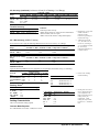
Safety Symbols
Instruction manual symbol affixed to
product. Indicates that the user must refer to
the manual for specific WARNING or
CAUTION information to avoid personal
injury or damage to the product.
Indicates the field wiring terminal that must
be connected to earth ground before
operating the equipment — protects against
electrical shock in case of fault.
or
Alternating current (AC)
Direct current (DC).
WARNING, RISK OF ELECTRIC SHOCK.
WARNING
Calls attention to a procedure, practice, or
condition that could cause bodily injury or
death.
CAUTION
Calls attention to a procedure, practice, or
condition that could possibly cause damage to
equipment or permanent loss of data.
Frame or chassis ground terminal—typically
connects to the equipment's metal frame.
WARNINGS
The following general safety precautions must be observed during all phases of operation, service, and repair of this product. Failure to
comply with these precautions or with specific warnings elsewhere in this manual violates safety standards of design, manufacture, and
intended use of the product. Agilent Technologies assumes no liability for the customer's failure to comply with these requirements.
Ground the equipment: For Safety Class 1 equipment (equipment having a protective earth terminal), an uninterruptible safety earth
ground must be provided from the mains power source to the product input wiring terminals or supplied power cable.
DO NOT operate the product in an explosive atmosphere or in the presence of flammable gases or fumes.
For continued protection against fire, replace the line fuse(s) only with fuse(s) of the same voltage and current rating and type. DO NOT
use repaired fuses or short-circuited fuse holders.
Keep away from live circuits: Operating personnel must not remove equipment covers or shields. Procedures involving the removal of
covers or shields are for use by service-trained personnel only. Under certain conditions, dangerous voltages may exist even with the
equipment switched off. To avoid dangerous electrical shock, DO NOT perform procedures involving cover or shield removal unless you
are qualified to do so.
DO NOT operate damaged equipment: Whenever it is possible that the safety protection features built into this product have been
impaired, either through physical damage, excessive moisture, or any other reason, REMOVE POWER and do not use the product until
safe operation can be verified by service-trained personnel. If necessary, return the product to Agilent for service and repair to ensure that
safety features are maintained.
DO NOT service or adjust alone: Do not attempt internal service or adjustment unless another person, capable of rendering first aid and
resuscitation, is present.
DO NOT substitute parts or modify equipment: Because of the danger of introducing additional hazards, do not install substitute parts
or perform any unauthorized modification to the product. Return the product to Agilent for service and repair to ensure that safety features
are maintained.
Measuring high voltages is always hazardous: ALL multimeter input terminals (both front and rear) must be considered hazardous
whenever inputs greater than 42V (dc or peak) are connected to ANY input terminal.
Permanent wiring of hazardous voltage or sources capable of delivering grater than 150 VA should be labeled, fused, or in some other
way protected against accidental bridging or equipment failure.
DO NOT leave measurement terminals energized when not in use.
DO NOT use the front/rear switch to multiplex hazardous signals between the front and rear terminals of the multimeter.
3
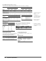
DECLARATION OF CONFORMITY
According to ISO/IEC Guide 22 and CEN/CENELEC EN 45014
Manufacturer’s Name:
Manufacturer’s Address:
Agilent Technologies, Incorporated
815 14th ST. S.W.
Loveland, CO 80537
USA
Declares, that the product
Product Name:
Model Number:
Product Options:
Multimeter
3458A
This declaration covers all options of the above product(s).
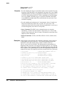
Conforms with the following European Directives:
The product herewith complies with the requirements of the Low Voltage Directive 73/23/EEC and the EMC Directive 89/336/EEC
(including 93/68/EEC) and carries the CE Marking accordingly
Conforms with the following product standards:
EMC
Standard
Limit
IEC 61326-1:1997+A1:1998 / EN 61326-1:1997+A1:1998
CISPR 11:1990 / EN 55011:1991
IEC 61000-4-2:1995+A1:1998 / EN 61000-4-2:1995
IEC 61000-4-3:1995 / EN 61000-4-3:1995
IEC 61000-4-4:1995 / EN 61000-4-4:1995
IEC 61000-4-5:1995 / EN 61000-4-5:1995
IEC 61000-4-6:1996 / EN 61000-4-6:1996
IEC 61000-4-11:1994 / EN 61000-4-11:1994
Canada: ICES-001:1998
Australia/New Zealand: AS/NZS 2064.1
Group 1 Class A
4kV CD, 8kV AD
3 V/m, 80-1000 MHz
0.5kV signal lines, 1kV power lines
0.5 kV line-line, 1 kV line-ground
3V, 0.15-80 MHz I cycle, 100%
Dips: 30% 10ms; 60% 100ms
Interrupt > 95%@5000ms
The product was tested in a typical configuration with Agilent Technologies test systems.
Safety
IEC 61010-1:1990+A1:1992+A2:1995 / EN 61010-1:1993+A2:1995
Canada: CSA C22.2 No. 1010.1:1992
UL 3111-1: 1994
8 March 2001
Ray Corson
Date
Product Regulation Program Manager
For further information, please contact your local Agilent Technologies sales office, agent or distributor.
Authorized EU-representative: Agilent Technologies Deutschland GmbH, Herrenberger Strabe 130, D 71034 Böblingen, Germany
Revision: B.01
4
Issue Date: March 2001
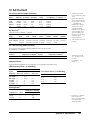
Preface
This manual contains installation information, operating and programming information, and configuration information for
the 3458A Multimeter. The manual consists of the following chapters:
Chapter 1 Installation and Maintenance
This chapter contains information on initial inspection, installation, and maintenance. It also contains lists of the
multimeter' s available options and accessories.
Chapter 2 Getting Started
This chapter covers the fundamentals of multimeter operation. It shows you how to use the multimeter's front panel, how to
send commands to the multimeter from remote, and how to retrieve data from remote.
Chapter 3 Configuring for Measurements
This chapter shows how to configure the multimeter for all types of measurements except digitizing (digitizing is covered
in Chapter 5). This chapter also shows you how to use subprogram and state memory, the input buffer, and the status
register.
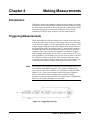
Chapter 4 Making Measurements
This chapter discusses the methods for triggering measurements, discusses the reading formats, shows how to use reading
memory, and how to transfer readings across the GPIB bus. This chapter also discusses how to increase the reading rate,
how to use the multimeter's EXTOUT signal, and how to use the math operations.
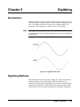
Chapter 5 Digitizing
Digitizing is the process of converting a continuous analog signal into a series of discrete samples (readings). This chapter
discusses the various ways to digitize signals, the importance of the sampling rate, and how to use level triggering.
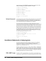
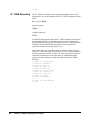
Chapter 6 Command Reference
This chapter discusses the multimeter's language (HPML) and contains detailed descriptions of each command in the
language. Commands are listed in alphabetical order.
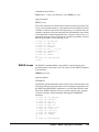
Chapter 7 BASIC Programming Language
This chapter describes the BASIC commands supported by the 3458A's internal BASIC language operating system. With
this feature, many of your special requirements can be easily satisfied by writing and downloading a simple BASIC
subprogram to customize the multimeter's behavior.
Appendices
The appendices contain the multimeter's specifications, information on the GPIB commands recognized by the multimeter,
information on locking-out the front/rear terminals switch, and contains product notes concerning digitizing and
maximizing the multimeter's reading rate and throughput.
5
6
Contents
Chapter 1 Installation and Maintenance
Introduction ........................................................... 15
Initial Inspection .................................................... 15
Options and Accessories ........................................ 16
Installing the Multimeter ....................................... 17
Grounding Requirements ................................. 17
Line Power Requirements ................................ 17
Setting the Line Voltage Switches ................... 18
Installing the Line Power Fuse ......................... 18
Power Cords ..................................................... 18
Connecting the GPIB Cable ............................. 19
The GPIB Address ............................................ 20
Mounting the Multimeter ................................. 20
Installation Verification .................................... 21
Maintenance ........................................................... 21
Replacing the Line Power Fuse ........................ 21
Replacing a Current Fuse ................................. 21
Repair Service .................................................. 22
Chapter 2 Getting Started
Introduction ........................................................... 25
Before Applying Power ......................................... 25
Applying Power ..................................................... 25
Power-On Self-Test .......................................... 25
Power-On State ................................................. 25
The Display ...................................................... 26
Operating from the Front Panel ............................. 27
Making a Measurement .................................... 28
Changing the Measurement Function ............... 28
Autorange and Manual Ranging ....................... 29
Self-Test ........................................................... 30
Reading the Error Register ............................... 31
Resetting the Multimeter .................................. 32
Using the Configuration Keys .......................... 32
Using the MENU Keys ..................................... 36
Query Commands ............................................. 37
Display Control ................................................ 37
Digits Displayed ............................................... 39
Recall ................................................................ 39
User-Defined Keys ........................................... 40
Installing the Keyboard Overlay ...................... 41
Operating from Remote ......................................... 42
Input/Output Statements ................................... 42
Reading the GPIB Address ............................... 42
Changing the GPIB Address ............................ 43
Sending a Remote Command ........................... 43
Getting Data from the Multimeter ................... 43
The Local Key .................................................. 44
Chapter 3 Configuring for Measurements
Introduction ........................................................... 47
General Configuration ........................................... 47
Self-Test ........................................................... 47
Reading the Error Registers ............................. 48
Calibration ........................................................ 48
Selecting the Input Terminals .......................... 50
Guarding .......................................................... 51
Suspending Readings ....................................... 51
Presetting the Multimeter ................................. 52
Specifying a Measurement Function ............... 53
Autorange ......................................................... 53
Specifying the Range ....................................... 54
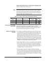
Configuring for DC or Resistance Measurements 54
DC Voltage ...................................................... 54
DC Current ....................................................... 55
Resistance ........................................................ 56
Configuring the A/D Converter ....................... 58
Autozero ........................................................... 61
Offset Compensation ....................................... 62
Fixed Input Resistance ..................................... 62
Configuring for AC Measurements ....................... 62
AC or AC+DC Voltage .................................... 62
AC or AC+DC Current .................................... 64
Frequency or Period ......................................... 65
Specifying Bandwidth ...................................... 66
Setting the Integration Time ............................ 67
Specifying Resolution ...................................... 68
Configuring for Ratio Measurements .................... 70
Specifying Ratio Measurements ...................... 71
Using Subprogram Memory .................................. 71
Storing a Subprogram ...................................... 71
Executing a Subprogram .................................. 72
Suspending Subprogram Execution ................. 72
Nested Subprograms ........................................ 73
Autostart Subprogram ...................................... 73
Compressing Subprograms .............................. 73
Deleting Subprograms ..................................... 74
Using State Memory ............................................. 74
Storing States ................................................... 74
Recalling States ................................................ 74
Contents 7
Deleting States .................................................. 75
Using the Input Buffer ........................................... 75
Using the Status Register ....................................... 75
Reading the Status Register .............................. 77
Interrupts .......................................................... 77
Chapter 4 Making Measurements
Introduction ........................................................... 81
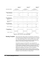
Triggering Measurements ...................................... 81
The Trigger Arm Event .................................... 82
The Trigger Event ............................................ 82
The Sample Event ............................................ 82
Event Choices ................................................... 82
Making Continuous Readings .......................... 82
Making Single Readings .................................. 83
Making Multiple Readings ............................... 83
Multiple Trigger Arming .................................. 84
Making Synchronous Readings ........................ 84
Making Timed Readings .................................. 85
Making Delayed Readings ............................... 86
External Triggering .......................................... 87
Event Combinations ......................................... 88
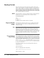
Reading Formats .................................................... 92
ASCII ................................................................ 92
Single and Double Integer ................................ 92
Single Real ....................................................... 93
Using Reading Memory ......................................... 94
Memory Formats .............................................. 95
Recalling Readings ........................................... 96
Sending Readings Across the Bus ......................... 98
Output Formats ................................................. 98
Output Termination .......................................... 99
Using the SINT or DINT Output Format ......... 99
Using the SREAL Output Format .................. 101
Using the DREAL Output Format .................. 101
Increasing the Reading Rate ................................ 102
High-Speed Mode ........................................... 102
Configuring for Fast Readings ....................... 103
High-Speed Transfer across GPIB ................. 107
High-Speed Transfer from Memory ............... 108
Determining the Reading Rate ....................... 109
The EXTOUT Signal ........................................... 110
Reading Complete .......................................... 112
Burst Complete ............................................... 113
Input Complete ............................................... 114
Aperture Waveform ........................................ 114
Service Request .............................................. 114
EXTOUT ONCE ............................................ 115
8 Contents
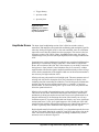
Math Operations .................................................. 116
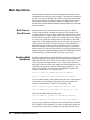
Real-Time vs. Post-Process ........................... 116
Enabling Math Operations ............................. 116
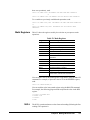
Math Registers ............................................... 117
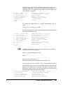
NULL ............................................................. 117
SCALE ........................................................... 119
Percent ............................................................ 120
DB .................................................................. 120
DBM .............................................................. 121
Statistics ......................................................... 122
Pass/Fail ......................................................... 123
FILTER .......................................................... 124
RMS ............................................................... 125
Measuring Temperature ................................. 125
Chapter 5 Digitizing
Introduction ......................................................... 129
Digitizing Methods .............................................. 129
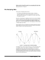
The Sampling Rate .............................................. 131
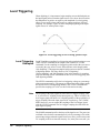
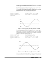
Level Triggering .................................................. 132
Level Triggering Examples ............................ 132
Level Filtering ................................................ 134
DCV Digitizing ................................................... 134
DCV Remarks ................................................ 135
DCV Example ................................................ 136
Direct-Sampling .................................................. 137
Direct Sampling Remarks .............................. 138
Direct Sampling Example .............................. 139
Sub-Sampling ...................................................... 139
Sub-Sampling Fundamentals ......................... 140
The Sync Source Event .................................. 141
Sub-Sampling Remarks ................................. 143
Sending Samples to Memory ......................... 144
Sending Samples to the Controller ................ 144
Viewing Sampled Data ....................................... 146
Chapter 6 Command Reference
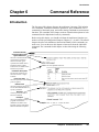
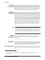
Introduction ......................................................... 151
Language Conventions ................................... 152
Command Termination .................................. 152
Multiple Commands ....................................... 152
Parameters ...................................................... 152
Query Commands .......................................... 153
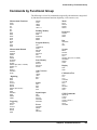
Commands by Functional Group ........................ 155
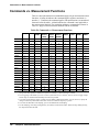
Commands vs. Measurement Functions ............. 156
ACAL ............................................................. 157
ACBAND ....................................................... 158
ACDCI, ACDCV, ACI, ACV ........................ 159
ADDRESS ..................................................... 159
APER .............................................................. 160
ARANGE ....................................................... 160
AUXERR? ...................................................... 161
AZERO ........................................................... 162
BEEP .............................................................. 164
CAL ................................................................ 164
CALL .............................................................. 164
CALNUM? ..................................................... 165
CALSTR ......................................................... 165
COMPRESS ................................................... 166
CONT ............................................................. 167
CSB ................................................................ 167
DCI, DCV ....................................................... 168
DEFEAT ......................................................... 168
DEFKEY ........................................................ 169
DELAY .......................................................... 170
DELSUB ........................................................ 171
DIAGNOST .................................................... 171
DISP ............................................................... 171
DSAC, DSDC ................................................. 172
EMASK .......................................................... 174
END ................................................................ 176
ERR? .............................................................. 177
ERRSTR? ....................................................... 178
EXTOUT ........................................................ 178
FIXEDZ .......................................................... 180
FREQ .............................................................. 181
FSOURCE ...................................................... 182
FUNC ............................................................. 183
ID? .................................................................. 185
INBUF ............................................................ 185
ISCALE? ........................................................ 187
LEVEL ........................................................... 188
LFILTER ........................................................ 190
LFREQ ........................................................... 190
LINE? ............................................................. 192
LOCK ............................................................. 192
MATH ............................................................ 193
MCOUNT? ..................................................... 195
MEM .............................................................. 196
MENU ............................................................ 197
MFORMAT .................................................... 198
MMATH ......................................................... 199
MSIZE ............................................................ 202
NDIG .............................................................. 203
NPLC .............................................................. 204
NRDGS .......................................................... 206
OCOMP .......................................................... 208
OFORMAT .................................................... 209
OHM, OHMF ................................................. 213
OPT? .............................................................. 213
PAUSE ........................................................... 214
PER ................................................................ 215
PRESET ......................................................... 216
PURGE .......................................................... 218
QFORMAT .................................................... 218
R ..................................................................... 220
RANGE .......................................................... 220
RATIO ........................................................... 223
RES ................................................................ 224
RESET ........................................................... 225
REV? .............................................................. 227
RMATH ......................................................... 227
RMEM ........................................................... 228
RQS ................................................................ 229
RSTATE ........................................................ 230
SCAL ............................................................. 231
SCRATCH ..................................................... 231
SECURE ........................................................ 231
SETACV ........................................................ 232
SLOPE ........................................................... 233
SMATH .......................................................... 234
SRQ ................................................................ 235
SSAC, SSDC .................................................. 236
SSPARM? ...................................................... 239
SSRC .............................................................. 239
SSTATE ......................................................... 243
STB? .............................................................. 244
SUB ................................................................ 245
SUBEND ........................................................ 247
SWEEP .......................................................... 247
T ..................................................................... 250
TARM ............................................................ 250
TBUFF ........................................................... 252
TEMP? ........................................................... 253
TERM ............................................................ 253
TEST .............................................................. 254
TIMER ........................................................... 254
TONE ............................................................. 255
TRIG .............................................................. 255
Chapter 7 BASIC Language for the 3458A
Introduction ......................................................... 261
How It Works ...................................................... 261
BASIC Language Commands ............................. 262
Variables and Arrays ...................................... 262
Contents 9
Math Operations ............................................. 262
Subprogram Definition/Deletion .................... 263
Subprogram Execution Commands ................ 263
Looping and Branching .................................. 263
Binary Programs ............................................. 263
New Multimeter Commands ............................... 264
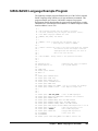
3458A BASIC Language Example Program ....... 265
Variables and Arrays ........................................... 266
Type Declarations ........................................... 266
Type Conversions ........................................... 267
Using Variables .............................................. 267
Arrays ............................................................. 268
General Purpose Math ......................................... 269
Math Operators ............................................... 270
Math Hierarchy ............................................... 272
Math Errors ..................................................... 272
Making Comparisons Work ........................... 272
Subprograms ........................................................ 273
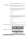
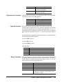
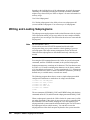
Writing and Loading Subprograms ..................... 274
Subprogram Command Types ............................. 275
Definition/Deletion Commands ..................... 275
Execution Commands ..................................... 277
Conditional Statements in Subprograms ............. 278
FOR...NEXT Loops ........................................ 278
WHILE Loops ................................................ 279
IF...THEN Branching ..................................... 280
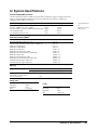
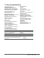
Appendix A
Specifications
Appendix B GPIB Commands
Introduction ......................................................... 303
ABORT 7 (IFC) .............................................. 304
CLEAR (DCL or SDC) .................................. 304
LOCAL (GTL) ............................................... 304
LOCAL LOCKOUT (LLO) ........................... 305
REMOTE ........................................................ 305
SPOLL (Serial Poll) ....................................... 306
TRIGGER (GET) ........................................... 307
Appendix C
Procedure to Lock Out Front/Rear
Terminals and Guard Terminal
Switches
Introduction ......................................................... 311
Tools Required .................................................... 311
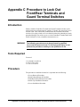
Procedure ............................................................. 311
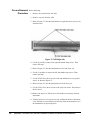
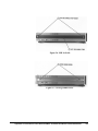
Covers Removal Procedure ............................ 312
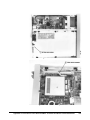
Guard Pushrod Removal Procedure ............... 314
Front/Rear Pushrod Removal Procedure ........ 314
Switch Cap Installation Procedure ................. 316
10 Contents
Covers Installation Procedure ........................ 318
Appendix D
Optimizing Throughout and
Reading Rate
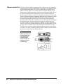
Introducing the 3458A ........................................ 321
Application Oriented Command Language ... 321
Intrinsically Slow Measurements ................... 321
Maximizing the Testing Speed ............................ 322
Program Memory ........................................... 322
State Storage .................................................. 322
Reading Analysis ........................................... 322
Task Grouping and Sequence ........................ 322
System Uptime ............................................... 323
Purpose ................................................................ 323
Topics Covered in the Product Note include: 323
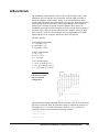
DC Volts, DC Current and Resistance ................ 323
Optimizing Through the DCV Path ............... 324
DC Current ..................................................... 326
Resistance ...................................................... 326
Optimizing Through the Track-and-Hold Path
(Direct Sampling and Subsampling) .............. 328
AC Volts and AC Current ................................... 328
Analog ACV .................................................. 328
Synchronous ACV ........................................ 328
Random ACV ................................................. 328
Comparison of ACV Modes .......................... 329
AC Current ..................................................... 329
Frequency and Period .................................... 330
Optimizing the Testing Process Through Task
Allocation ............................................................ 330
Math Operations ............................................. 330
Data Storage ................................................... 330
Output Formats .............................................. 331
State Storage and Program Memory .............. 331
Measurement List ........................................... 332
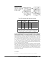
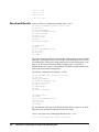
A Benchmark ...................................................... 333
Benchmark Results ........................................ 334
Still Faster ...................................................... 338
Appendix E
High Resolution Digitizing With the
3458A
Introduction ......................................................... 349
Speed with Resolution ......................................... 349
Digitizing Analog Signals .............................. 350
Avoiding Aliasing .......................................... 350
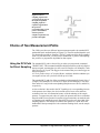
Choice of Two Measurement Paths .................... 351
Using the DCV Path for Direct Sampling ...... 351
Using the Track-and-Hold Path for Direct or
Sequential Sampling ...................................... 352
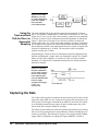
Capturing the Data ............................................... 352
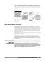
High Speed Data Transfers .................................. 355
Software Help The Wave Form Analysis Library 355
Starter Main Program ..................................... 357
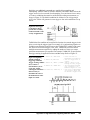
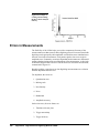
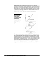
Errors in Measurements ...................................... 358
Amplitude Errors ........................................... 359
Trigger and Timebase Errors ......................... 361
Contents 11
12 Contents
Chapter 1
Installation and Maintenance
Introduction ........................................................... 15
Initial Inspection .................................................... 15
Options and Accessories ........................................ 16
Installing the Multimeter ....................................... 17
Grounding Requirements ................................. 17
Line Power Requirements ................................ 17
Setting the Line Voltage Switches ................... 18
Installing the Line Power Fuse ......................... 18
Power Cords ..................................................... 18
Connecting the GPIB Cable ............................. 19
The GPIB Address ............................................ 20
Mounting the Multimeter ................................. 20
Installation Verification .................................... 21
Maintenance ........................................................... 21
Replacing the Line Power Fuse ........................ 21
Replacing a Current Fuse ................................. 21
Repair Service .................................................. 22
Serial Number ............................................. 22
Shipping Instructions .................................. 22
Chapter 1 Installation and Maintenance
13
14
Chapter 1 Installation and Maintenance
Chapter 1
Installation and Maintenance
Introduction
This chapter contains information on initial inspection, installation, and
maintenance. It also contains lists of the multimeter's available options and
accessories. It's a good idea to read this chapter before making any electrical
connections to the multimeter.
Initial Inspection
WARNING
If any of the following symptoms exist, or are expected, remove
the multimeter from service:
1.
2.
3.
4.
Visible damage.
Severe transport stress.
Prolonged storage under adverse conditions.
Failure to perform intended measurements or functions.
Do not use multimeter until safe operation can be verified by
service trained personnel.
The multimeter was carefully inspected before it left the factory. It should
be undamaged and in proper working order upon receipt. If the shipping
container or cushioning material is damaged, keep it, until the contents of
the shipment have been checked and the multimeter has been inspected.
When you unpack the multimeter, verify that the following items, in addition
to this user’s guide, are included:
• Quick Reference Guide (Qty. 1)
• Calibration Manual (Qty. 1)
• Line Power Cord (Qty. 1)
• Replacement line power fuses: 500mA T (Qty 1 for 220/240 operation),
•
•
1.5A NTD (Qty 1 for 100/120 operation)
Keyboard Overlay (Qty. 2)
Switch Lockout Caps (Qty. 2)
If the multimeter is damaged or the contents are incomplete, promptly notify
the nearest Agilent Technologies office.
Chapter 1 Installation and Maintenance
15
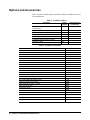
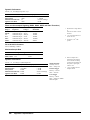
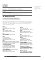
Options and Accessories
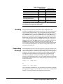
Table 1 lists the available options, and Table 2 lists the available accessories
for the multimeter.
Table 1. Available Options
Description
Extended Reading Memory (expands to a total
of 148k-bytes)
High Stability Reference (4ppm/year)
Waveform Analysis Library
Front Handle Kit
Rack Flange Kit
Rack Flange Kit (with handles)
2 Additional Years of Return to Agilent
Hardware support
Option
Number
001
Part Number for
Field Retrofit
03458-87901
002
005
907
908
909
03458-80002
03458-80005
5061-9688
5061-9674
5061-9675
W30
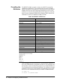
Table 2. Available Accessories
Description
Extra User’s Guide, Quick Reference Guide, and Calibration Manual
Extra Quick Reference Guide
Extra Calibration Manual
User-Defined Key Overlay
Switch Lockout Cap (Qty 1)
1 Meter GPIB Cable
2 Meter GPIB Cable
4 Meter GPIB Cable
0.5 Meter GPIB Cable
Test Lead Set
Low thermal test lead pair, spade lug to spade lug, 0.9m
Low thermal test lead pair, spade lug to banana, 0.9m
Low thermal test lead pair, banana to banana, 0.9m
RF Detector Probe
40kV AC/DC High Voltage Probe
5kV AC/DC 1MHz High Voltage Probe
Clamp-On AC/DC Current Probe
Kelvin Probe Set (4-wires, 1m each)
Kelvin Clip Set (2 each)
Temperature Probe
16
2252 W Thermistor
Model or Part Number
03458-90000
03458-90005
03458-90015
03458-84303
03458-44103
10833A
10833B
10833C
10833D
34118A
11053A
11174A
11058A
34301A
34300A
34119A
34302A
11059A
11062A
34303A
40653A
5k W Thermistor
40653B
1Ok W Thermistor
40653C
100 W RTD stainless steel probe, alpha = 0.00385
40654A
100 W RTD for surface mount, alpha = 0.00385
40654B
Chapter 1 Installation and Maintenance
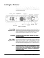
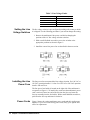
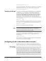
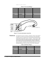
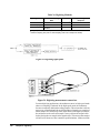
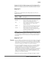
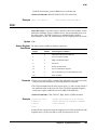
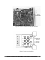
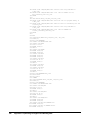
Installing the Multimeter
This section discusses the multimeter's grounding and power requirements
and contains instructions for installing the multimeter. (Refer to Appendix
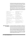
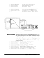
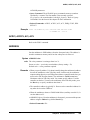
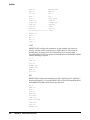
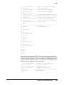
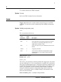
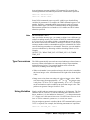
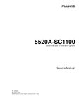
C for instructions on how to install the switch lockout caps.) Figure 1 shows
the multimeter's rear panel. Many of the rear panel connectors and switches
are referenced in this section.
Figure 1. Rear panel
Grounding
Requirements
WARNING
The multimeter comes with a three-conductor AC power cable (see Figure 3).
The power cable must be connected to an approved three-contact electrical
outlet that has its ground conductor connected to an electrical ground (safety
ground). The multimeter's power jack and the supplied power cable meet
International Electrotechnical Commission (IEC) safety standards.
For protection from electrical shock, the power cord ground
must not be defeated.
Line Power
Requirements
You can operate the multimeter from a single phase power source delivering
100 VAC, 120 VAC, 220 VAC, or 240 VAC (all values RMS), at 48 to 440
Hz. The power line voltage can vary by +/- 10% but cannot exceed 250 VAC
RMS. Maximum power consumption is 80 VA (Volt-Amps). The nominal
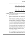
line voltage values and their corresponding limits are shown in Table 3.
Caution
Possible multimeter damage. Before connecting the multimeter
to an AC power source, verify that the multimeter’s line voltage
selection switches are set to match the AC line voltage and that
the proper line fuse is installed. These topics are discussed in
the following sections.
Chapter 1 Installation and Maintenance
17
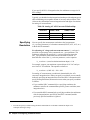
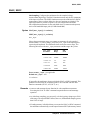
Table 3. Line Voltage Limits
Nominal Value (RMS)
100 VAC
120 VAC
220 VAC
240 VAC
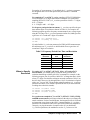
Setting the Line
Voltage Switches
Allowable Limits (RMS)
90 VAC to 110 VAC
108 VAC to 132 VAC
198 VAC to 242 VAC
216 VAC to 250 VAC
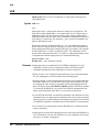
The line voltage selection is pre configured according to the country to which
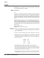
it is shipped. Use the following procedure if you need to change this setting:
1. Remove the multimeter's line power cord before changing the
positions of the AC line voltage selection switches
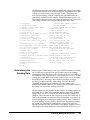
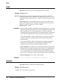
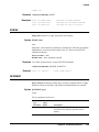
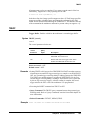
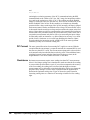
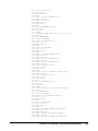
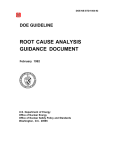
2. With a small flat blade screwdriver, move the switches to the
appropriate positions as shown in Figure 2
3. Install the correct line power fuse as described in the next section.
Figure 2. AC line voltage switch positions
Installing the Line
Power Fuse
The line power fuse must match the line voltage selection. For 100 VAC or
120 VAC operation install a 1.5A fuse. For 220 VAC or 240 VAC operation
install a 500 mAT fuse.
The line power fuse holder is located on the right side of the multimeter's
rear panel (see Figure 1). To install a fuse, make sure the multimeter's power
cord is removed. Insert one end of the fuse into the fuse cap. Insert the
fuse/cap assembly into the fuse holder. With a small flatblade screwdriver,
push in on the fuse cap and rotate it clockwise.
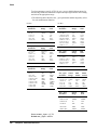
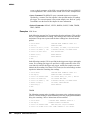
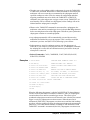
Power Cords
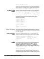
18
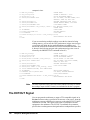
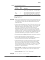
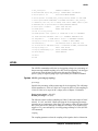
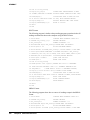
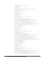
Figure 3 shows the various multimeter power cords and their Agilent part
numbers. If you received the wrong power cord, notify your Agilent sales
office for replacement.
Chapter 1 Installation and Maintenance
Power Cords
Australia Denmark Europe
Great Brittain
Switzerland
U.S.A
Country
Part Number
Option
Voltage
Australia
8120-1369
901
250V 6A
Denmark
1820-2956
912
259V 6A
Europe
1820-1689
902
250V 6A
Great Brittain
1820-1351
900
250V 6A
Switzerland
1820-2104
906
250V 6A
United States
1820-1378
903
120 10A
United States
1820-0698
904
240V 10A
U.S.A.
Power cords supplied by Agilent have polarities matched to the power input socket
on the instrument.
NOTE: Plugs are viewed from connector and. Shape of molded plug may vary
within country
*CSA certification includes only these power cords
Figure 3. Power Cords
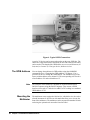
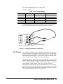
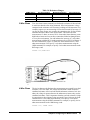
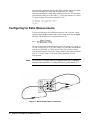
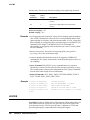
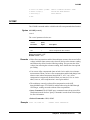
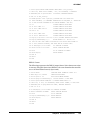
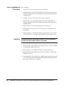
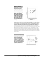
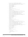
Connecting the GPIB
Cable
Attach the GPIB1 cable to the 24-pin GPIB connector on the rear panel of
the multimeter. Finger tighten the two screws on the cable connector.
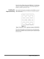
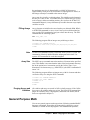
Figure 4 shows a typical GPIB connection between the multimeter and a
controller.
1. GPIB (General Purpose Interface Bus) is an implementation of IEEE Standard 488-1978 and ANSI MC 1.1.
Chapter 1 Installation and Maintenance
19
Figure 4. Typical GPIB Connections
A total of 15 devices can be connected together on the same GPIB bus. The
cables have single male/female connectors on each end so that several cables
can be stacked. The length of the GPIB cables must not exceed 20 meters (65
feet) total, or 2 meters (6.5 feet) per device, whichever is less.
20
The GPIB Address
You can change the multimeter's GPIB address using the ADDRESS
command. Refer to "Changing the GPIB Address", in Chapter 2, for a
procedure on how to change the GPIB address. The multimeter leaves the
factory with the address set to decimal 22. The corresponding ASCII code is
a listen address of 6 and a talk address of V.
Note
The examples in this manual are intended for Hewlett-Packard Series
200\300 computers using the BASIC language. They assume a GPIB
interface select code of 7 and a device address of 22 resulting in a combined
GPIB address of 722.
Mounting the
Multimeter
The multimeter comes equipped with four feet, which allow it to be used as
a bench instrument. It also has two tilt stands that allow you to elevate the
front of the multimeter. The multimeter can be mounted in a standard 19-inch
rack using the optional rack mount kits listed in Table 1.
Chapter 1 Installation and Maintenance
Installation
Verification
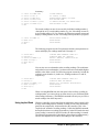
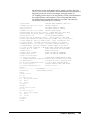
The following program verifies that the multimeter is operating and can
communicate with the controller over the GPIB bus.
10
20
30
40
50
PRINTER IS 1
OUTPUT 722;"ID?"
ENTER 722; IDENT$
PRINT IDENT$
END
If the multimeter has been correctly installed, the message HP 3458A will
be printed on the designated system printer. If no message is printed, make
sure power is applied to the multimeter. Also check the GPIB connections,
the interface address setting, and the multimeter's address.
Maintenance
This section describes how to replace the multimeter's fuses and how to
obtain repair service.
Replacing the Line
Power Fuse
The line power fuse holder is located on the right side of the multimeter's
rear panel. Before replacing the fuse, disconnect the multimeter's line power.
To replace the fuse, use a small flatblade screwdriver to push in on the fuse
cap and rotate it counterclockwise. Remove the fuse cap and replace the fuse
with the appropriate type (see Table 4). (The Agilent part number for the gray
line power fuse cap is 2110-0565.) Re-install the fuse cap and apply power.
Table 4. Replacement Power Line Fuses and Caps
Line Voltage
Power Line Fuse
100 or 120 VAC (Nominal) 1.5A NTD, Agilent Part Number 2110-0043
220 or 240 VAC (Nominal) 500mAT SB, Agilent Part Number
2110-0202
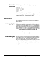
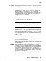
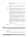
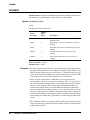
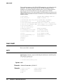
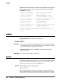
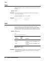
Replacing a Current
Fuse
Each of the front and rear current terminals (labeled I) contains a current fuse.
To access the fuse, unscrew (rotate counterclockwise) the current terminal
binding post knob until it stops. Push in on the terminal and rotate it
clockwise. The entire terminal/fuse assembly can now be removed as shown
in Figure 5. If necessary, replace the fuse with a 1A 250V NTD fuse (Agilent
part number 2110-0001). (CAUTION: never use a slow-blow fuse as a
current fuse; multimeter damage will result.) Replace the terminal/fuse
assembly by pushing it in and turning counterclockwise until the assembly
locks in place.
Chapter 1 Installation and Maintenance
21
Figure 5. Current Terminal/Fuse Assembly
22
Repair Service
You may have the multimeter repaired at an Agilent Technologies service
center whether it is under warranty or not. Contact the nearest Agilent Sales
Office for shipping instructions prior to returning the instrument.
Serial Number
Agilent instruments are identified by a two part, ten-character serial number
of the form 0000A00000. The first four digits are the same for all identical
products. They change only when a change is made to the product. The letter
indicates the country of origin. An A indicates the product was made in the
United States of America. The last five digits are unique to each instrument.
The multimeter's serial number is located to the right of the multimeter's rear
terminals.
Shipping Instructions
If you need to ship the multimeter, be certain that the multimeter is in a
protective package (use the original shipping containers and cushioning
materials) to prevent transit damage. Such damage is not covered by
warranty. Attach a tag to the shipment identifying the owner and indicating
the service or repair needed. Include the model number and serial number of
the multimeter. We suggest that you insure the shipment.
Chapter 1 Installation and Maintenance
Chapter 2
Getting Started
Introduction ........................................................... 25
Before Applying Power ......................................... 25
Applying Power ..................................................... 25
Power-On Self-Test .......................................... 25
Power-On State ................................................. 25
The Display ...................................................... 26
Operating from the Front Panel ............................. 27
Making a Measurement .................................... 28
Changing the Measurement Function ............... 28
Autorange and Manual Ranging ....................... 29
Hold ............................................................. 29
Manual Ranging .......................................... 30
Self-Test ........................................................... 30
Reading the Error Register ............................... 31
Resetting the Multimeter .................................. 32
Using the Configuration Keys .......................... 32
Selecting a Parameter .................................. 33
Default Values ............................................. 34
Numeric Parameters .................................... 34
Exponential Parameters ............................... 35
Multiple Parameters .................................... 35
Using the MENU Keys ..................................... 36
Query Commands ............................................. 37
Standard Queries ......................................... 37
Additional Queries ...................................... 37
Display Control ................................................ 37
Clearing the Display .................................... 37
Display Editing ............................................ 38
Viewing Long Displays ............................... 38
MORE INFO Display ................................. 39
Digits Displayed ............................................... 39
Recall ................................................................ 39
User-Defined Keys ........................................... 40
Installing the Keyboard Overlay ...................... 41
Operating from Remote ......................................... 42
Input/Output Statements ................................... 42
Reading the GPIB Address ............................... 42
Changing the GPIB Address ............................ 43
Sending a Remote Command ........................... 43
Getting Data from the Multimeter .................... 43
The Local Key .................................................. 44
Chapter 2 Getting Started
23
24
Chapter 2 Getting Started
Chapter 2
Getting Started
Introduction
This chapter is intended for the novice multimeter user. It shows you how to
use the multimeter's front panel, how to send commands to the multimeter
from remote, and how to retrieve data from remote. Since front panel
operation is discussed first, it covers important topics such as the power-on
state, display annunciators, the various ways to select or enter parameters,
and how to make a simple DC voltage measurement. For this reason, you
should read the entire chapter even if you intend to use the multimeter
primarily from remote.
Before Applying Power
• Make sure the line voltage selection switches on the multimeter's rear
panel are set to match the local line voltage.
• Make sure the proper line fuse is installed.
If you have any questions concerning installation or power requirements,
refer to Chapter 1.
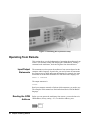
Applying Power
To turn on the multimeter, depress the front panel Power switch. If the
multimeter does not appear to turn on, verify that the multimeter is connected
to line power. If line power is not the problem, remove the power cord and
check the line power fuse and the line voltage selection switch settings.
Power-On Self-Test
When power is applied, the multimeter performs a limited power-on self-test.
This test verifies that the multimeter is operating but does not necessarily
verify that measurements will be accurate.
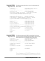
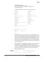
Power-On State
When the power-on self-test is finished, the multimeter beeps once,
automatically triggers, automatically selects the range, and performs DC
voltage measurements. Also, the multimeter has set many of its commands
to predefined power-on values as shown in Table 5, This is called the
power-on state.
Chapter 2 Getting Started
25
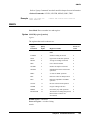
Table 5. Power-On State
Command
Description
ACBAND 20, 2E6
AC bandwidth 20Hz - 2MHz
AZERO ON
Autozero enabled
DCV AUTO
DC voltage, autorange
DEFEAT OFF
Defeat disabled
DELAY -1
Default delay
DISP ON
Display Enabled
EMASK 32767
Enable all error conditions
END OFF
Disable GPIB EOI function
EXTOUT ICOMP, NEG
Input complete EXTOUT signal, negative pulse
FIXEDZ OFF
Disable fixed input resistance
FSOURCE ACV
Frequency and period source is AC voltage
INBUF OFF
Disable input buffer
LEVEL 0, AC
Level trigger at 0%, AC-coupled
LFILTER OFF
Level filter disabled
LFREQ 50 or 60
Measured line frequency rounded to 50 or 60Hz
LOCK OFF
Keyboard enabled
MATH OFF
Disable real-time math
MEM OFF
Disable reading memory (last memory operation = FIFO)
MFORMAT SREAL
Single real reading memory format
MMATH OFF
Disable post-process math
NDIG 7
Display 7.5 digits
NPLC 10
10 power line cycles of integration time
NRDGS 1, AUTO
1 reading per trigger, auto sample event
OCOMP OFF
Disable offset compensated resistance
OFORMAT ASCII
ASCII output format
QFORMAT NORM
Normal query format
RATIO OFF
Disable ratio measurements
RQS 0 (or 8)
0 disables status register conditions (if power-on
SRQ was on when power was removed, value = 8).
SETACV ANA
Analog AC voltage mode
SLOPE POS
Positive slope for level triggering
SSRC LEVEL, AUTO
Level sync source event, auto synchronous AC voltage
SWEEP lOOE-9,1024
Sample interval 100 nanoseconds, 1024 samples
TARM AUTO
Auto trigger arm event
TBUFF OFF
Disable external trigger buffering
TIMER 1
1 second timer interval
TRIG AUTO
Auto trigger event
All math registers set to 0 except:
DEGREE = 20
The Display
26
Chapter 2 Getting Started
REF=l
SCALE = 1
RES=50
PERC = 1
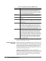
In the power-on state, the display is continuously updated with each new DC
voltage reading. Along the bottom of the display are a series of annunciators.
These annunciators alert you to a variety of conditions. For example, the
SMPL annunciator flashes whenever the multimeter has completed a
reading. Table 6 describes the meaning of each display annunciator.
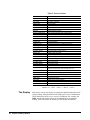
Table 6. Display Annunciators
Display Annunciator
Note
Description
SMPL
Flashes whenever a reading is completed
REM
The multimeter is in the GPIB remote mode
SRQ
The multimeter has generated a GPIB service request
TALK
The multimeter is addressed to talk on GPIB
LSTN
The multimeter is addressed to listen on GPIB
AZERO OFF
Autozero is disabled
MRNG
Autorange is disabled (the multimeter is using a fixed range)
MATH
One or two real-time or post-process math operations enabled
ERR
An error has been detected
SHIFT
The shift key has been pressed
MORE INFO
More information concerning the present configuration is available
(use the right arrow key to view the information)
If the ERR annunciator is illuminated at this point, an error was detected
during or after the power-on self-test. You will learn how to determine the
error later in this chapter in “Reading the Error Register”.
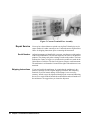
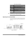
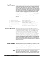
Operating from the Front Panel
This section shows you how to make a simple DC voltage measurement, how
to use the various front panel keys, and describes the multimeter functions
important to front panel operation. Figure 6 shows the multimeter's front
panel features.
Figure 6. Front Panel
Chapter 2 Getting Started
27
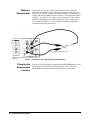
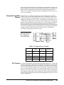
Making a
Measurement
In the power-on state, DC voltage measurements are selected and the
multimeter automatically triggers and selects the range. In the power-on
state, you can make DC voltage measurements simply by connecting a DC
voltage to the input terminals as shown in Figure 7. The connections shown
in Figure 7 also apply for AC voltage, 2-wire resistance, AC+DC voltage,
digitizing, and frequency or period measurements from a voltage input
source. Refer to Chapter 3 for a CAUTlON concerning the multimeter's
maximum input voltage and current.
Figure 7. Standard 2-wire (plus guard) measurements
Changing the
Measurement
Function
28
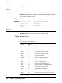
Chapter 2 Getting Started
The row of keys located directly under the display (FUNCTION keys) select
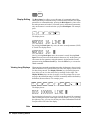
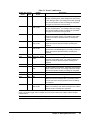
the multimeter's standard measurement functions. Table 7 shows the
FUNCTION keys and the measurement function selected by each.
Table 7. Function Keys
In addition to the functions selected by the FUNCTION keys, the multimeter
can perform direct-sampled or sub-sampled digitizing, ratio measurements,
and AC or AC+DC voltage measurements using the synchronous or random
measurement methods. These functions can be selected from the front panel
by accessing the appropriate command(s) using the alphabetic menu keys
(these keys are discussed later in this section under "Using the MENU
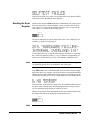
Keys"). For more information on any measurement function or method, refer
to Chapter 1.
Autorange and
Manual Ranging
Hold
In the power-on state, the multimeter automatically selects the appropriate
measurement range. This is called autorange. In many cases, you will
probably want to continue using autorange. However, you have two other
ranging choices: hold and manual ranging.
This choice allows you to shut off autoranging. To do this, let autorange
choose a range and then press:
Hold
Note
When you press the blue shift key, the display’s SHIFT annunicator
illuminates. The shifted keyboard functions are printed in blue above the
keys.
Chapter 2 Getting Started
29
Notice the display's MRNG (manual range) annunciator is on. This
annunciator is on whenever you are not using autorange.
Manual Ranging
The second choice lets you manually select the range. When the multimeter
is in the measurement mode (that is, the multimeter is making and displaying
measurements or the display is showing OVLD) you can change the range
by pressing the up or down arrow keys. To go to a higher range, press:
By repeatedly pressing the up arrow key, you can increment up to the highest
range. When you reach the highest range, pressing the up arrow key no longer
changes the range. To go to a lower range, press:
By repeatedly pressing the down arrow key, you can decrement down to the
lowest range. When you reach the lowest range, pressing the down arrow key
no longer changes the range. To return to autoranging, press:
Auto
Self-Test
Note
When you applied power to the multimeter, it automatically performed a
limited power-on self-test. Before you start making measurements, however,
you may want to have more confidence that the multimeter is fully
operational. This is the job of the self-test. The self-test performs a series of
tests that check the multimeter's operability and accuracy.
Always disconnect any input signals before you run self-test. If you leave
an input signal connected to the multimeter, it cause a self-test failure.
The self-test takes over 50 seconds. To run self-test press:
Test
If the self-test passed, the display shows:
When self-test passes, you have a high confidence that the multimeter is
operational and, assuming proper calibration and autocalibration, that
measurements will be accurate.
If any of the tests failed, the ERR annunciator illuminates and the display
shows:
30
Chapter 2 Getting Started
If the self-test failed, one or more error conditions have been detected. Refer
to the next section "Reading the Error Register".
Reading the Error
Register
Whenever the display's ERR annunciator is illuminated, one or more errors
have been detected. A record of hardware errors is stored in the auxiliary
error register. A record of programming and syntax errors is stored in the
error register. To read the error record(s), press:
Error
_
The lowest numbered error and a description of the error is displayed. For
example, a possible error message is:
Use the right arrow key to view the entire message. When the error message
has a 100-series numeric prefix (e.g., 105), it indicates a programming or
syntax error. A 200-series prefix (e.g., 209) indicates a hardware error.
Note
When you get a hardware error (200-series prefix), run the self-test again. If
you repeatedly get the error, the multimeter may need repair.
If the ERR annunciator is still illuminated, more errors have been recorded.
Repeat the above key sequence until all errors have been read and the ERR
annunciator is no longer illuminated. When you have read all the errors, the
error annunciator goes off. If you try to read another error, the display shows:
You do not have to run self-test to get an error. The multimeter detects errors
that occur while entering data, when changing functions or ranges, and so
on. The multimeter beeps whenever it detects an error.
Whenever you want to clear information (such as an error description) from
the display and return it to displaying measurements, press:
Clear
Back
Space
Note
You can also clear the display by repeatedly pressing the Back Space key
Chapter 2 Getting Started
31
(unshifted).
Resetting the
Multimeter
Many times during operation, you may wish to return to the power-on state.
The front panel Reset key returns you to the power-on state without having
to cycle the multimeter's power. To reset the multimeter, press:
Reset
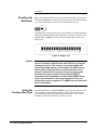
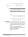
The multimeter begins the reset process with a display test which illuminates
all display elements including the annunciators as shown in Figure 8. (By
holding down the Reset key, the multimeter continuously performs its
display test).
Figure 8. Display Test
32
Caution
Pressing the shifted front panel Reset key performs the
power-on sequence which has the same effect as cycling the
multimeter’s power. This destroys any stored reading and
compressed subprograms, sets the power-on SRQ bit in the
status register (these functions are discussed later in this
manual), resets the A/D converter reference frequency and
performs the power-on self test. Executing the RESET
command from the alphabetic command menu (MENU keys)
returns the mulitmeter to the power-on state but does not
perform the power-on sequence. The MENU keys are discussed
later in this chapter.
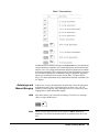
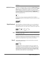
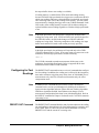
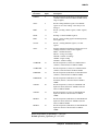
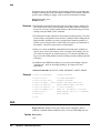
Using the
Configuration Keys
The configuration keys (unshifted MENU keys) let you rapidly access the
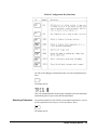
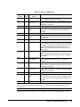
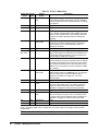
most frequently used multimeter features. Table 8 shows each key, the
corresponding multimeter command, and the function of each. (These
functions are discussed in detail in Chapters 3 and 4.)
Chapter 2 Getting Started
Table 8. Configuration Key Functions
We will use the Trig key to demonstrate how to use the configuration keys.
Press:
Trig
The display shows:
This is the command header for the trigger command. Notice the multimeter
automatically placed a space after the command header.
Selecting a Parameter
For parameters that have a list of choices (non-numeric parameters), you can
use the up and down arrow keys to review the choices. Press:
The display shows:
Chapter 2 Getting Started
33
Press:
The display shows:
When using the up or down arrow keys, if you step past the last parameter
choice, a wraparound occurs to the other end of the menu. Suppose you want
to suspend triggering. Press the up or down arrow key until the display shows:
Press:
Enter
You have now changed the trigger event from auto (power-on state) to HOLD
which causes the multimeter to stop taking readings. (Triggering is discussed
in detail in Chapter 4.)
Default Values
Most parameters have a default value. A default value is the value selected
when you execute a command but do not specify a value. For example, the
default value for the trigger parameter is SGL. Press:
Trig
Press:
Enter
Notice that the multimeter takes one reading and then stops (after the single
trigger, the trigger event becomes HOLD regardless of the previously
specified trigger event). You can also enter-1 to select the default value.
Press:
Enter
_
1
Enter
The multimeter again takes a single reading and then stops.
Numeric Parameters
34
Chapter 2 Getting Started
Some commands use numeric parameters, A numeric parameter is the actual
value used by the multimeter. We will use the NPLC configuration key to
demonstrate numeric parameters. Press:
NPLC
This display shows:
Notice that if you press the up or down arrow key, no parameter choice is
displayed. This means there is no menu and you must enter a number. For
example, press:
Enter
1
You have now selected 1 power line cycle of integration time for the A/D
converter. Integration time is the actual time that the A/D converter measures
the input signal. (Integration time is discussed in detail in Chapter 3.)
Exponential Parameters
You can also enter numeric parameters using exponential notation. For
example, press:
NPLC
1
0
0
E
_
3
Enter
You have now selected 0.1 power line cycles of integration time. At this
point, you should reset the multimeter to return the number of power line
cycles to 10 by pressing:
Reset
Multiple Parameters
Many commands have more than one parameter. (Multiple parameters are
separated by commas.) We will use the NRDGS command, which has two
parameters, as an example of a command with multiple parameters. Press:
N Rdge/
Trig
The display shows:
The first parameter in the NRDGS command is a numeric parameter that
specifies the number of readings made per trigger event. For example, to
specify 5 readings per trigger event, press:
5
The display shows:
Chapter 2 Getting Started
35
The second parameter of the NRDGS command specifies the event that
initiates each reading. Since this is not a numeric parameter, a menu is
available for this parameter. Use the up or down arrow keys to cycle through
the list of choices. When the display shows:
Execute the command by pressing:
Enter
You have now selected five readings per trigger event. If you execute the
TRIG SGL command, for example, the multimeter will take five readings
and then stop. (The NRDGS command is discussed in detail in Chapter 4.)
Using the MENU Keys
In addition to the configuration keys, the multimeter has an alphabetic
command menu that can be accessed using the shifted MENU keys labeled
C, E, L, N, R, S, and T. Each of these letters corresponds to the area you
will enter into the command menu. For example, to enter the menu with
commands starting with T, press:
T
Recall
State
The display shows:
You can now use the Menu Scroll keys (up or down arrow keys} to step
through the menu in alphabetical order (down arrow key) or in reverse
alphabetical order (up arrow key). For example, starting with the TARM
display shown above, by pressing the down arrow key once, the display
shows the next command in alphabetical order (TBUFF). (You can also press
and hold the up or down arrow key to rapidly step through the menu.) Once
you have found the desired command, you can press the Enter key to execute
it immediately (using default parameter values if applicable). If you need to
specify command parameter(s), with the command displayed, press the right
arrow key or the comma key (or, if the first parameter is numeric, a numeric
key). This selects the command and allows you to specify or select
parameter(s) using the procedures described earlier in this section.
There are two alphabetic menus available: FULL and SHORT. You can
select between these menus using the shifted Menu key. The specified menu
choice is stored in continuous memory (not lost when power is removed).
The FULL menu contains all commands except query commands that can
be constructed by appending a question mark to a command (e.g., BEEP,
BEEP?). (Query commands are discussed next.) The SHORT menu
36
Chapter 2 Getting Started
eliminates the GPIB bus-related commands, commands that are seldom used
from the front panel, and any commands that have dedicated front panel keys
(e.g., the NPLC key or the Trig key).
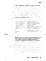
Query Commands
Standard Queries
There are a number of commands in the alphabetic command directory that
end with a question mark. These commands are called query commands since
each returns a response to a particular question. For example, access the
LINE? query command from the command menu and press the Enter key.
The multimeter responds to this query command by measuring and
displaying the power line frequency. (Use the right arrow key to view the
entire response.) As another example, access the TEMP? command from the
command menu and press Enter. This command returns the multimeter's
internal temperature in degrees Centigrade.
The FULL command menu contains the following standard query
commands:
AUXERR?
CAL?
CALNUM?
ERR?
ERRSTR?
ID?
ISCALE?
LINE?
Additional Queries
MCOUNT?
MSIZE?
OPT?
REV?
SSPARM?
STB?
TEMP?
In addition to the queries listed above, you can create others by appending a
question mark to any command that can be used to program the multimeter.
For example, the AZERO command (Auto Zero configuration key) enables
or disables the autozero function. You can determine the present autozero
mode by appending a question mark to the AZERO command. To do this,
press:
?
Auto
Zero
Store
State
The multimeter responds by displaying the present autozero mode (power-on
mode = ON). (Notice that this command is immediately executed; you do
not have to press the Enter key.)
Note
The QFORMAT command can be used to specify whether query responses
will be numeric, alpha, or a combination of alpha and numeric. Refer to the
QFORMAT command, in Chapter 6, for more information.
Display Control
The shifted Clear key, the Back Space key, and the Display/Window keys
(left and right arrow keys) allow you to control the display.
Clearing the Display
Whenever you want to clear information (such as a query response) from the
display, press:
Chapter 2 Getting Started
37
Clear
Back
Space
Display Editing
The Back Space key allows you to edit parts of a command string while
entering the string or when the string is recalled (discussed later), For alpha
parameters or command headers, pressing the Back Space key once erases
the entire parameter or header. For commas, spaces, and numeric parameters,
only one character is erased each time you press Back Space. For example,
press:
0
1
N Rdge/
Trig
The display shows:
By pressing the Back Space key once, the entire second parameter (LINE)
is erased. The display shows:
Now by pressing Back Space once, the comma is erased. Pressing Back
Space two more times erases both numeric characters (10). At this point, you
can reenter the first parameter using the numeric keypad and the second
parameter using the Menu Scroll keys. Press the Enter key to execute the
edited command.
Viewing Long Displays
When entering commands containing more than 16 characters, the previously
entered characters are scrolled off the left side of the display to make room
for those being entered. The Display/Window keys (left and right arrow
keys) allow you to view the entire line by scrolling it left or right. The
Display/Window keys can also be used to view long strings such as error
messages, the calibration string (CALSTR? command), and user-defined key
definitions (discussed later). For example, press:
N Rgds/
Trig
1
0
0
0
0
0
The display shows:
By pressing the left arrow key, you can view the first part of the command
while scrolling the last part off the right side of the display. Now, by pressing
the right arrow key, you can view the last part of the command and scroll the
first part off the left side of the display.
Note
38
Chapter 2 Getting Started
Think of the display as a window you can move to the left or right using the
arrow keys.
MORE INFO Display
In addition to scrolling the display left and right, the Display/Window keys
allow you to view additional display information when the display's MORE
INFO annunciator is illuminated. For example, access and execute the
SETACV RNDM command from the alphabetic command menu. Now press
the front panel ACV key. Notice that the multimeter's MORE INFO
annunciator is illuminated. This means there is more information available
than is being displayed. Press:
The present AC voltage measurement method (SETACV RNDM) is
displayed. At this point, reset the multimeter to return it to the power-on state
by pressing:
Reset
Digits Displayed
When the multimeter is displaying readings, you can vary the number of
digits it displays. In the power-on state, the display is showing 7.5 digits
although the multimeter is resolving 8.5 digits. To display all 8.5 digits, press:
N
Offset
Comp 9
Note
8
Enter
The display’s leftmost digit (referred to as a 1/2 digit) is implied when you
are specifying display digits.
The NDlG command only masks digits from the display. It does not affect
readings sent to reading memory or transferred over the GPIB bus. Also, you
cannot view more digits than are being resolved by the multimeter.
Recall
You can easily recall the last executed command without repeating the
command entry process. Press:
Recall
Enter
The display will show the last command executed. (You cannot recall
commands that are executed immediately such as Reset or DCV, or any
command that contained the calibration security code.) By repeating the
above keystrokes, you can recall previously executed commands. After
recalling the desired command, you can modify it (see "Display Editing"
earlier in this section) and execute it by pressing Enter.
Chapter 2 Getting Started
39
User-Defined Keys
You can assign a string of one or more commands to each of the USER keys
labeled f0 - f9. After assigning a string to one of these keys (maximum string
length is 40 characters), pressing that key displays the string on the display.
You can then execute the string by pressing the Enter key. The Def Key
allows you to assign a command string to any of the user-defined keys. For
example, to assign the commands NRDGS 10,AUTO; TRIG SGL (the
semicolon links multiple commands) to the user-defined key f0, press:
Def Key
°
0
The display shows:
You can now enter the command string by pressing:
N Rgds/
Trig
1
0
R
Trig
To store the string (this does not execute the string, it merely assigns it to the
user-defined key), press:
Enter
To access and execute the string assigned to key f0, press:
0
Enter
The multimeter will take 10 readings and then stop.
As a special keyboard feature, you can access the string assigned to a key
without pressing the shift key (except when you are in the process of entering
a command). For example, you can access and execute the string assigned to
key f0 by pressing:
0
Enter
You can also assign commands from the command menu to user-defined
keys. You cannot assign a command using an immediate execute key (DCV,
ACV, etc.) Instead, you must access that command from the menu. Key
definitions stored from the front panel can be edited from the front panel.
(You cannot edit a key definition that was downloaded from the controller.)
Editing is done by pressing the user-defined key and, while the string is
displayed, editing the string as described under "Display Editing" earlier in
40
Chapter 2 Getting Started
this section. After editing the string, press the Enter key to execute the string.
(The previous string is still assigned to the user-defined key.) An edited string
cannot be re-assigned to a user-defined key. If you want to change a key
definition, you must repeat the above steps.
Installing the
Keyboard Overlay
Figure 9 shows the keyboard over-lay that fits over the USER keys. You can
write on this overlay with a pencil to identify the command(s) assigned to
each user-defined key.
Figure 9. Keyboard overlay (Agilent part number 03458-84303)
The overlay is held in place by two tabs that secure it to the collar around
numeric key 5. To install the overlay, insert the overlay's left tab into the left
side of the collar. Bend the overlay as shown in Figure 10 and press the right
tab into the collar.
Chapter 2 Getting Started
41
Figure 10. Installing the keyboard overlay
Operating from Remote
This section shows you the fundamentals of operating the multimeter from
remote. This includes reading and changing the GPIB address, sending a
command to the multimeter, and retrieving data from the multimeter.
Input/Output
Statements
The statements used to operate the multimeter from remote depend on the
computer and its language. In particular, you need to know the statements
the computer uses to input and output information. For example, the input
statements for the Hewlett-Packard Series 200/300 BASIC language are:
ENTER or TRANSFER
The output statement is:
OUTPUT
Read your computer manuals to find out which statements you need to use.
The examples in this manual use Hewlett-Packard Series 200/300 BASIC
language.
Reading the GPIB
Address
Before you can operate the multimeter from remote, you need to know its
GPIB address (factory setting = 22). To check the address, press:
Address
Local
42
Chapter 2 Getting Started
A typical display is:
The displayed response is the device address. When sending a remote
command, you append this address to the GPIB interface's select code
(normally 7). For example, if the select code is 7 and the device address is
22, the combination is 722.
Changing the GPIB
Address
Every device on the GPIB bus must have a unique address. If you need to
change the multimeter's address, access the ADDRESS command from the
command menu (MENU keys), with the display showing:
You can enter the new address. For example, press:
1
5
Enter
You have now changed the address to 15. If you want to change the address
back to 22, repeat the above procedure (or use the Recall key) and specify
22 instead of 15.
Sending a Remote
Command
To send the multimeter a remote command, combine the computer's output
statement with the GPIB select code, the device address, and finally, the
multimeter command. For example, to make the multimeter beep, send:
OUTPUT 722; "BEEP"
Notice the display's REM and LSTN annunciators are illuminated. This
means the multimeter is in the remote mode and has been addressed to listen
(receive a command).
Getting Data from the
Multimeter
The multimeter is capable of outputting readings and responses to query
commands. As an example, have the multimeter generate a response to a
query command by sending:
OUTPUT 722;"ID?"
When you send a query from remote, the multimeter does not display the
response as it did when you executed the command from its front panel.
Instead, the multimeter sends the response to its output buffer. The output
buffer is a register that holds a query response or a single reading until it is
read by the computer or replaced by new information. Use the computer's
input statement to get the response from the output buffer. For example, the
following program reads the response (HP 3458A) and prints it.
10 ENTER 722;A$
20 PRINT A$
Chapter 2 Getting Started
43
30 END
The same technique allows you to get readings from the multimeter.
Whenever the multimeter is making measurements and you have not enabled
reading memory (reading memory is discussed in Chapter 4), you can get a
reading by running the following program.
10 ENTER 722;A
20 PRINT A
30 END
The Local Key
When you press a key on the multimeter's keyboard while operating from
remote, the multimeter does not respond. This is because the multimeter is
in the remote mode (as indicated by the display's REM annunciator) and is
ignoring all but the Local key. To return the multimeter to local mode, press:
Local
44
Chapter 2 Getting Started
Chapter 3
Configuring for Measurements
Introduction ........................................................... 47
General Configuration ........................................... 47
Self-Test ........................................................... 47
Reading the Error Registers ............................. 48
Calibration ........................................................ 48
Autocalibration ............................................ 48
Running Autocal ......................................... 49
When to Use Autocal .................................. 49
Selecting the Input Terminals ........................... 50
Guarding ........................................................... 51
Suspending Readings ....................................... 51
Presetting the Multimeter ................................. 52
Specifying a Measurement Function ................ 53
Autorange ......................................................... 53
Specifying the Range ........................................ 54
Configuring for DC or Resistance Measurements . 54
DC Voltage ....................................................... 54
DC Current ....................................................... 55
Resistance ......................................................... 56
2-Wire Ohms ............................................... 57
4-Wire Ohms ............................................... 57
Configuring the A/D Converter ........................ 58
The Reference Frequency ........................... 58
Setting the Integration Time ........................ 59
Specifying Resolution ................................. 60
Autozero ........................................................... 61
Offset Compensation ........................................ 62
Fixed Input Resistance ..................................... 62
Configuring for AC Measurements ....................... 62
AC or AC+DC Voltage .................................... 62
Synchronous Sampling Conversion ............ 63
Analog RMS Conversion ............................ 64
Random Sampling Conversion ................... 64
Specifying the AC Voltage Method ............ 64
AC or AC+DC Current .................................... 64
Frequency or Period ......................................... 65
Specifying Bandwidth ...................................... 66
Setting the Integration Time ............................. 67
Specifying Resolution ...................................... 68
When to Specify Resolution ........................ 69
Configuring for Ratio Measurements .................... 70
Specifying Ratio Measurements ....................... 71
Using Subprogram Memory .................................. 71
Storing a Subprogram ....................................... 71
Executing a Subprogram .................................. 72
Suspending Subprogram Execution ................. 72
Nested Subprograms ........................................ 73
Autostart Subprogram ...................................... 73
Compressing Subprograms .............................. 73
Deleting Subprograms ..................................... 74
Using State Memory ............................................. 74
Storing States ................................................... 74
Recalling States ................................................ 74
Deleting States ................................................. 75
Using the Input Buffer .......................................... 75
Using the Status Register ...................................... 75
Reading the Status Register ............................. 77
Interrupts .......................................................... 77
Chapter 3 Configuring for Measurements
45
46
Chapter 3 Configuring for Measurements
Chapter 3
Configuring for Measurements
Introduction
This chapter shows how to configure the multimeter for all types of
measurements except digitizing.1 This chapter also shows you how to use
subprogram and state memory, the input buffer, and the status register. After
using this chapter to configure the multimeter for your application, you can
then use Chapter 4 to learn how to trigger readings and transfer them to
reading memory or the GBIB output buffer. The major sections in this chapter
are:
• General Configuration
• Configuring for DC or Resistance Measurements
• Configuring for AC Measurements
• Configuring for Ratio Measurements
• Using Subprogram Memory
• Using State Memory
• Using the Input Buffer
• Using the Status Register
General Configuration
This section discusses the multimeter's self-test, calibration requirements,
and general configuration topics that apply to many or all measurement
functions.
Self-Test
Prior to configuring for measurements, you should run the self-test to ensure
the multimeter is operational. The self-test takes approximately 50 seconds
to complete. To run self-test, send:
OUTPUT 722;"TEST"
If self-test passes, you have a high confidence level that the multimeter is
operational and, assuming proper calibration, that measurements will be
accurate. If one or more tests fail, the multimeter sets bit(s) in the auxiliary
error register, which also sets bit 0 in the error register, and the display's ERR
1. This chapter doesn’t address digitizing specifically although most of the information under General
Configuration does apply to digitizing. Refer to Chapter 5 for specific information on digitizing.
Chapter 3 Configuring for Measurements
47
annunciator illuminates.
Reading the Error
Registers
When a hardware error is detected, the multimeter sets a bit in the auxiliary,
error register and also sets bit 0 in the error register.When a programming
error is detected, the multimeter sets a bit in the error register only.
The ERRSTR? command reads each error (one error at a time) and then clears
the corresponding bit. If one or more bits are set in the auxiliary error register,
the ERRSTR? command reads that register first before proceeding to the
error register. The ERRSTR? command returns two responses. The first
response is the decimal: value of the least significant (lowest numbered) set
bit. The second response is a message (string) explaining the error (the
maximum string length returned is 200 characters). After reading a bit, the
ERRSTR? command clears that bit.
The following program uses the ERRSTR? command to read all errors, one
error at a time. After all set bits have been read and cleared, or if there were
no set bits in either register, the ERRSTR? command returns 0, "NO
ERROR".
10 OPTION BASE 1
20 DIM A$[200]
30 OUTPUT 722; "ERRSTR?"
40 ENTER 722; A,A$
50 PRINT A,A$
60 IF A>0 THEN GOTO 30
70 END
!COMPUTER ARRAY NUMBERING
STARTS WITH 1
!DIMENSION STRING VARIABLE
!READS ERROR MESSAGE
!ENTERS NUMERIC INTO A,
STRING INTO A$
!PRINTS RESPONSES
!LOOP TO READ EACH ERROR
The ERR? and AUXERR? commands return the decimal sum of all set bits
in the error register and the auxiliary error register, respectively. Refer to
these commands in Chapter 6 for example programs and listings of the
possible errors.
Calibration
The multimeter has two forms of calibration: external calibration and
autocalibration. The external calibration involves a procedure using external
reference sources. Refer to the 3458 Calibration Manual for more
information on the external calibration.
The CALNUM? query command returns a number indicating the number of
times the multimeter has been externally calibrated. By routinely checking
this number, you can monitor the calibrations performed on the multimeter.
The following program reads and returns the present calibration number.
10
20
30
40
Autocalibration
48
OUTPUT 722;"CALNUM?"
ENTER 722;A
PRINT A
END
The multimeter has four autocalibration (autocal) routines: DCV, AC,
OHMS, and ALL. These routines improve short-term accuracy for many or
all measurement functions, but are not substitutes for periodic external
calibration of the multimeter. The measurement functions affected by each
Chapter 3 Configuring for Measurements
routine are:
• The DCV routine enhances all measurement functions. This routine takes
about
1 minute to perform.
• The AC routine performs specific enhancements for AC or AC+DC voltage
(all measurement methods), AC or AC+DC current, direct- or sub-sampled
digitizing (AC- or DC-coupled), frequency, and period measurements. The
AC routine takes about 1 minute to perform.
• The OHMS routine performs specific enhancements for 2 or 4-wire ohms.
DC current, and AC current measurements. The OHMS routine takes about
10 minutes to perform.
• The ALL routine enhances all measurement functions by performing all of
the above routines. The ALL routine takes about 11 minutes to perform.
Note
You should not cycle power or reset the multimeter while an autocal routine
is being performed. If you do, the multimeter generates the ACAL
REQUIRED error (since many or all of its autocal constants have been
erased). You must then perform the ALL routine to eliminate the error.
Since the DCV routine applies to all measurement functions, you should
perform the DCV autocal before performing the AC or OHMS autocal, or
perform ALL of the routines (see second example below).
Running Autocal
Suppose you intend to make 4-wire ohms measurements. The DCV autocal
routine increases the short term accuracy for all measurements and the
OHMS autocal enhances resistance measurements (and current
measurements). The following program performs the DCV autocal followed
by the OHMS autocal.
10 OUTPUT 722; "ACAL DCV"
20 OUTPUT 722; "ACAL OHMS"
30 END
If autocal is secured (it is not secured when shipped from the factory), you
must enter the security code to perform autocal; refer to the ACAL command
in Chapter 6 for more information. You can perform all of the autocal
routines (DCV first, followed by OHMS and AC) by sending:
OUTPUT 722; "ACAL ALL"
Always disconnect any input signals before performing autocal. If you leave
an input signal connected to the multimeter, it may adversely affect the
autocal and subsequent measurements.
When to Use Autocal
For maximum accuracy, we recommend performing ACAL ALL once every
24 hours or when the multimeter's temperature changes by ± 1°C from when
it was last externally calibrated or from the last autocal. (We recommend that
the calibrator store the multimeter's internal calibration temperature using
Chapter 3 Configuring for Measurements
49
the CALSTR command; this can be read later using the CALSTR?
command.) The following example shows how to use the TEMP? command
to monitor the multimeter's internal temperature (in degrees Celsius).
10
20
30
40
OUTPUT 722;"TEMP?"
ENTER 722;A
PRINT A
END
The autocal constants are stored in continuous memory (they remain intact
when power is removed). Therefore, it is not necessary to perform autocal
simply because power has been cycled.
Selecting the Input
Terminals
WARNING
The multimeter has both front and rear terminals for measurement
connections. The front panel Terminals switch allows you to select between
the two (depressed = Rear, out = Front). You cannot select the input
terminals from remote. The measurement connection illustrations in this
chapter show the front terminal connections only. For rear terminal
connections, connect each wire to the similarly labeled rear terminal. We
recommend high impedance, low dielectric absorption cables for all
measurement connections.
Only qualified, service trained personnel who are aware of the
hazards involved should remove or install the multimeter or
connect wiring to the multimeter. Disconnect the multimeter’s
power cord before removing any covers, changing the line
voltage selector switches, or installing or changing the line
power fuse.
Measuring high voltage is always hazardous. All multimeter
input terminals (both front and rear) must be considered as
hazardous whenever inputs in excess of 42V are connected to
any terminal. Regard all terminals as being at the same
potential as the highest voltage applied to any terminal.
Agilent recommends that the wiring installer attach a label to
any wiring having hazardous voltages. This label should be as
close to the input terminals as possible and should be an eye
catching color, such as red or yellow. Clearly indicate on the
label that high voltages may be present.
Caution
The current input terminals (I) are rated at ±1.5A peak with a
maximum non-destructive input of <1.25A RMS. Current inputs
are fuse protected. The multimeter’s input voltage ratings are:
Table 9: Input Ratings
Rated Input
HI to LO Input:
50
Chapter 3 Configuring for Measurements
± l000V peak
Maximum NonDestructive Input
±1200V peak
Table 9: Input Ratings
Rated Input
Maximum NonDestructive Input
HI/LO W Sense to LO Input:
± 200V peak
± 350V peak
HI to LO W Sense:Input:
± 200V peak
± 350V peak
LO Input to Guard:
± 200V peak
± 350V peak
Guard to Earth Ground:
± 500V peak
± 1000V peak
HI/LO Input, HI/LO W Sense, or I
terminal to earth ground:
± l000V peak
± 1500V peak
Front terminals to rear terminals:
± l000V peak
± l500V peak
The multimeter will be damaged if any of the above maximum
non-destructive inputs are exceeded.
Guarding
The measurement connection illustrations in this chapter show the
multimeter's Guard terminal connected to the low side of the measurement
source (guarded measurements). This configuration provides maximum
effective common mode rejection (ECMR) on the input terminals selected by
the Terminals switch, assuming the Guard switch is in the Open (out)
position. For non-guarded measurements, depress the Guard switch (TO
LO position) and do not connect the Guard terminal to the measurement
source. In the TO LO position, the Guard switch internally connects the
Guard terminal to the LO Input terminal on the terminals selected by the
Terminals switch. This configuration provides reduced ECMR.The
specifications in Appendix A shows the ECMR for guarded measurements.
We recommend high impedance, low dielectric absorption cables for all
measurement connections.
Suspending
Readings
In the multimeter's power-on state, the trigger arm, trigger, and sample events
are set to AUTO (these events are discussed in detail in Chapter 4). This
causes the multimeter to continuously take readings. Prior to configuring the
multimeter for measurements, you should suspend readings. Suspending
readings decreases the amount of time required for configuration and
prevents the possibility of undesired readings being placed in reading
memory or the GPIB output buffer. You can suspend readings by presetting
the multimeter (discussed next) or by setting the trigger arm or trigger event
to HOLD as follows:
OUTPUT 722; "TARM HOLD"
or
OUTPUT 722; "TRIG HOLD"
After configuring the multimeter, you can enable measurements by changing
the trigger arm or trigger event from HOLD to some other event. (Refer to
Chapter 2 for more information on triggering measurements).
Chapter 3 Configuring for Measurements
51
Presetting the
Multimeter
The PRESET NORM command is similar to the RESET command but
configures the multimeter to a good starting point for remote operation.
(RESET is primarily for front panel use.) It's a good idea to execute PRESET
NORM as the first step when configuring the multimeter since it sets the
multimeter to a known configuration and suspends readings by setting the
trigger event to synchronous (TRIG SYN) command. Table 10 shows the
commands executed by the PRESET NORM command.
Table 10: PRESET NORM State
Command
Description
ACBAND 20,2E+6
AC bandwidth 20Hz - 2MHz
AZERO ON
Autozero enabled
BEEP ON
Beeper enabled
DCV AUTO
DC voltage measurements, autorange
DELAY –1
Default delay
DISP ON
Display enabled
FIXEDZ OFF
Disable fixed input resistance
FSOURCE ACV
Frequency and period source is AC voltage
INBUF OFF
Disable input buffer
LOCK OFF
Keyboard enabled
MATH OFF
Disable real-time math
MEM OFF
Disable reading memory
MFORMAT SREAL
Single real reading memory format
MMATH OFF
Disable post-process math
NDIG 6
Display 6.5 digits
NPLC 1
1 power line cycle of integration time
NRDGS 1,AUTO
1 reading per trigger, auto sample event
OCOMP OFF
Disable offset compensated ohms
OFORMAT ASCII
ASCII output format
TARM AUTO
Auto trigger arm event
TIMER 1
1 second timer interval
TRIG SYN
Synchronous trigger event
All math registers set to 0 except:
DEGREE = 20
PERC = 1
REF = 1
RES = 50
SCALE = 1
When attempting to preset from remote, it is possible that the multimeter is
busy or the GPIB interface is being held. In either case, the multimeter will
not respond to a remote command. It's good practice to send the GPIB Device
Clear command prior to presetting the multimeter. The multimeter responds
immediately to the Device Clear command. The following program sends
the Device Clear command followed by the PRESET NORM command:
10 CLEAR 722
20 OUTPUT 722;"PRESET NORM"
52
Chapter 3 Configuring for Measurements
30 END
In addition to the PRESET NORM command, the multimeter has a PRESET
FAST command (configures for fast readings and transfers), which is
discussed in Chapter 4, and a PRESET DIG command (configures for DCV
digitizing) which is discussed in Chapter 5.
Specifying a
Measurement
Function
The first parameter of the FUNC command selects the measurement function.
For example, to specify DC voltage measurements, send:
OUTPUT 722;"FUNC DCV"
The FUNC command header is optional and can be omitted. For example,
you can specify DC voltage measurements simply by sending:
OUTPUT 722;"DCV"
The remaining examples in this chapter use the shortened (no FUNC header)
version. Table 11 shows the various measurement function parameters and
the function selected by each.
Table 11: Measurement Function Parameters
Function Parameter
Description
ACDCI
Selects AC current measurements, DC coupled
ACDCV
Selects AC voltage measurements, DC coupled
ACI
Selects AC current measurements, AC coupled
ACV
Selects AC voltage measurements, AC coupled
DCI
Selects DC current measurements
DCV
Selects DC voltage measurements
DSAC *
Direct sampling, AC coupled
DSDC *
Direct sampling, DC coupled
FREQ
Selects frequency measurements
OHM
Selects 2-wire ohms measurements
OHMF
Selects 4-wire ohms measurements
PER
Selects period measurements
SSAC *
Sub-sampling, AC coupled
SSDC *
Sub-sampling, DC coupled
* Refer to Chapter 5Digitizing for more information on these functions.
Autorange
When the autorange function is enabled, the multimeter samples the input
prior to each reading (when readings are being triggered) and automatically
selects the correct range. Since autorange requires sampling the input,
measurements made with autorange enabled take longer than measurements
made on a fixed range. In the power-on/PRESET NORM state, autorange is
enabled. If you intend to measure a fairly stable input signal, you can use the
ARANGE ONCE command to allow autorange to select the correct range
(when readings are triggered) and then disable autorange for subsequent
readings. This allows you to get the automatic range selection advantage of
autorange and also the speed advantage of readings made with autorange
disabled. To do this, send:
Chapter 3 Configuring for Measurements
53
OUTPUT 722;"ARANGE ONCE"
Now when triggering begins, the multimeter will select the correct range and
then disable autorange. Later, if you need to enable autorange, send:
OUTPUT 722; "ARANGE ON"
Specifying the Range
You specify a fixed range using the first parameter of one of the function
commands (ACV, DCV, OHM. etc.) or the RANGE command. This
parameter is called max._inputsince you specify it as the input signal's
maximum expected amplitude (or the maximum resistance for resistance
measurements). The multimeter then chooses the correct range. When
specifying max._input, use the absolute value of the input signal—no
negative numbers. For example, to specify DC voltage with a maximum input
of -2.5 volts, send:
OUTPUT 722; "DCV 2.5"
In this case, the multimeter selects the 10 VDC range. To specify a different
max_input(e.g. 15V) without changing the measurement function, send:
OUTPUT 722; "RANGE 15"
In this case, the multimeter selects the 100V range.
Note
For frequency and period measurements, the max._input parameter
specifies the maximum amplitude of the input signal. It does not specify the
frequency range (Hz) or the period range (seconds).
You select the autorange mode by defaulting the max._input parameter or by
specifying AUTO. For example, to select, autorange using the DCV
command, send:
OUTPUT 722; "DCV"
Refer to the FUNC or RANGE command in Chapter 6 for tables showing
the ranges for each measurement function.
Configuring for DC or Resistance Measurements
This section describes how to configure the multimeter for making DC
voltage, DC current, and 2-wire or 4-wire resistance (ohms) measurements.
DC Voltage
54
The multimeter measures DC voltage on any of five ranges. Table 12 shows
each DC voltage range and its full scale reading (which also shows the
maximum number of digits for the range). Table 12 also shows the maximum
resolution and the input resistance for each range. (Resolution is a function
of the specified integration time: refer to Setting the Integration Time later
in this section for more information.) Figure 11 shows the front terminal
connections for all types of voltage measurements. In the power-on/PRESET
NORM states. DC voltage measurements are selected. You can also specify
DC voltage measurements using the DCV command. For example, to specify
Chapter 3 Configuring for Measurements
DC voltage measurements on the 1V range, send:
OUTPUT 722;"DCV 1"
Table 12: DC Voltage Ranges
DCV Range
Full Scale Reading
Maximum Resolution
Input Resistance
100mV
120.00000mV
10nV
>10GW*
1V
1.20000000V
10nV
>lOGW*
10V
12.0000000V
100nV
>lOGW*
100V
120.000000V
1µV
10MW
1000V
1050.00000V
10µV
1OMW
* With FIXEDZ OFF. With FIXEDZ ON the input resistance is fixed at 10MW.
Refer to Fixed Input Resistance later in this chapter for more information.
Figure 11. Voltage measurement connections
DC Current
The multimeter measures current by placing an internal shunt resistor across
the input terminals, measuring the voltage across the resistor, and calculating
the current (current = voltage/resistance). The multimeter's front and rear
current inputs are protected by 1 A, 250V fuses. Figure 12 shows the front
terminal connections for all types of current measurements.
The multimeter measures DC current on any of eight ranges. Table 13 shows
each DC current range and its full-scale reading (the full scale reading also
shows the maximum number of digits for each range). Table 13 also shows
the maximum resolution and the shunt resistor used for each range.
(Resolution is a function of the specified integration time: refer to Setting
the Integration Time later in the section for more information.) You specify
DC current measurements using the DCI command. For example, to specify
DC current measurements on the 10µA range, send:
Chapter 3 Configuring for Measurements
55
OUTPUT 722;"DCI 10E-6"
Table 13: DC Current Ranges
DCI Range
Full Scale Reading
Maximum Resolution
Shunt Resistor
lOOnA
120.000nA
1pA
545.2kW
1µA
1.200000µA
1pA
45.2kW
10µA
12.000000µA
1pA
5.2kW
100µA
120.00000µA
10pA
730W
1mA
1.2000000mA
lOOpA
100W
10mA
12.000000mA
1nA
10W
100mA
120.00000mA
10nA
1W
1A
1.0500000A
100nA
0.1W
Figure 12. Current measurement connections
Resistance
The multimeter measures resistance by supplying a known current through
the unknown resistance being measured. The current passing through the
resistance generates a voltage across it. The multimeter measures this voltage
and calculates the unknown resistance (resistance = voltage/current). Table
14 shows each 2-and 4-wire ohms range and its full-scale reading (the full
scale reading also shows the maximum number of digits for each range).
Table 14 also shows the maximum resolution and current sourced for each
range. (Resolution is a function of the specified integration time: refer to
Setting the Integration Time later in this section for more information.)
Table 14: Resistance Ranges
OHM(F) Range
56
Full Scale Reading
Maximum Resolution
Current Sourced
10W
12.00000W
10mW
10mA
100W
120.00000W
10µW
1mA
1kW
1.2000000kW
100µW
1mA
10kW
12.000000kW
1mW
l00µA
100kW
120.00000kW
10mW
50µA
1MW
1.2000000MW
100mW
5µA
Chapter 3 Configuring for Measurements
Table 14: Resistance Ranges
OHM(F) Range
Full Scale Reading
Maximum Resolution
Current Sourced
10MW
12.000000MW
1W
500nA
100MW
120.00000MW
10W
500nA
1GW
1.2000000GW
100W
500nA
2-Wire Ohms
Two-wire ohms is most commonly used when the resistance of the test leads
is much less than the value being measured. If the lead resistance is large
compared to the resistance to be measured, readings will be inaccurate. For
example, suppose you are measuring a 1W resistor located 10 feet away. If
you use 24-gauge copper wire to make the connections, the 20 feet of leads
contribute about 0.5 ohms to the measurement. This makes the total
measurement 1.5 ohms--an error of 50%. Some other factors that may cause
high lead resistance are loose or dirty connections, kinked or damaged wires,
or a very hot environment. You can enhance the accuracy of 2-wire ohms
measurements with the NULL math operation (refer to NULL in Chapter 4
for more information). Figure 13 shows the front connections for 2-wire
ohms measurements. You specify 2-wire ohms measurements using the
OHM command. For example, to specify 2-wire ohms measurements on the
lkW range, send:
OUTPUT 722;"OHM 1E3"
Figure 13. 2-Wire ohms measurement connections
4-Wire Ohms
The 4-wire ohms mode eliminates the measurement error caused by test lead
resistance. In 2-wire ohms, the voltage measurement is made across the
combined resistance of the test leads and the unknown resistance. In 4-wire
ohms, the voltage is measured across the unknown resistance only, not the
combined resistance. This is important when the test lead resistance is high
in comparison to the resistance being measured. Figure 14 shows the front
connections for 4-wire ohms measurements. You specify 4-wire ohms
measurements using the OHMF command. For example, to specify 4-wire
ohms measurements on the 10MW range, send:
OUTPUT 722; "OHMF 10E6"
Chapter 3 Configuring for Measurements
57
Figure 14. 4-Wire ohms measurement connections
Configuring the A/D
Converter
The A/D converter's configuration determines the measurement speed,
resolution, accuracy, and normal mode rejection1 for DC or ohms
measurements. The factors that affect the A/D converter's configuration are
the reference frequency, the specified integration time, and the specified
resolution.
The Reference Frequency
When power is applied, the multimeter measures the power line frequency,
rounds the value to 50 Hz or 60 Hz, and sets the A/D converter's reference
frequency to the rounded value. (For a 400Hz power line frequency, the
multimeter uses 50Hz as the reference frequency, which is a subharmonic of
400Hz.) For DC or ohms measurements, the multimeter achieves normal
mode rejection (NMR) for noise at the reference frequency when the
integration time is ³1 power line cycle. See Setting the Integration Time
(following) for more information.
Changing the Reference
Frequency
For most operating conditions, the power-on reference frequency allows for
excellent NMR. However, for maximum NMR you should set the reference
frequency to the exact power line frequency. (If your power line frequency
is subject to drift, you may have to periodically correct the reference
frequency.) The following command measures the power line frequency and
sets the reference frequency to the exact measured value (for a 400Hz line
frequency. the multimeter divides the measured value by 8 and uses that as
the reference frequency).
OUTPUT 722;"LFREQ LINE”
You can also use the LFREQ command to directly specify the reference
frequency. This is particularly useful when the multimeter has a different
power line frequency than the device being measured. Suppose, for example,
1. Normal mode rejection (NMR) is the multimeter’s ability to reject noise at the power line frequency from DC
or ohms measurements.
58
Chapter 3 Configuring for Measurements
the multimeter has a power line frequency of 60 Hz and the device being
measured has a power line frequency of 50 Hz. For this application you can
achieve NMR by setting the reference frequency to 50 Hz as follows:
OUTPUT 722;"LFREQ 50"
Remember that whenever power is cycled or the front panel Reset key is
pressed, the reference frequency returns to the rounded value of 50 or 60 Hz.
Setting the Integration
Time
Integration time is the period of time that the A/D converter measures the
input signal. For DC or ohms measurements, the integration time determines
the measurement speed, accuracy, maximum digits of resolution, and the
amount of NMR for noise at the A/D converter's reference frequency, You
can specify integration time in terms of power line cycles (PLCs) using the
NPLC command or directly (in seconds) using the APER command. Since
the NPLC and APER commands both set the integration time, executing
either will cancel the integration time previously established by the other.
Specifying Power Line
Cycles
The multimeter achieves NMR for noise at the A/D converter's reference
frequency when the integration time is ³1 power line cycles. You can specify
integration time in terms of power line cycles (PLCs) using the NPLC
command. The multimeter multiplies the specified number of PLCs by the
period of the A/D converter's reference frequency (LFREQ command) to
determine the integration time. For example, the period of a 50 Hz power
line is l/50 = 20 msec. If you specify 10 PLCs, the integration time is 200
msec. In the power-on state, integration time is set to 10 PLCs. In the
PRESET NORM state, integration time is set to 1 PLC. To set the integration
time for the fastest measurements (with the lowest accuracy, lowest
resolution. and no NMR), send:
OUTPUT 722; "NPLC 0"
To specify the most accuracy, highest resolution, and 80dB of NMR for DC
or ohms measurements (with the slowest measurement speed), send:
OUTPUT 722;"NPLC 1000"
You can specify power line cycles in the following ranges:
• 0 - 1 PLC
(in .000006 PLC steps for 60Hz ref. frequency or. 000005 PLC
steps for 50Hz ref. frequency)
• 1- 10 PLC in 1 PLC steps
• 10 - 1000 PLCs in 10 PLC steps
Note
For integration times greater than 10 PLCs, the multimeter averages a
number of readings made using 10 PLCs of integration time. For example,
if you specify 60 PLCs, the multimeter averages six 10 PLC readings.
The wide range of PLC settings provides flexibility in the selection of
measurement speed. accuracy, resolution, and NMR. Typically, you should
Chapter 3 Configuring for Measurements
59
select the integration time that provides adequate speed while maintaining
an acceptable amount of resolution and NMR. The specifications tables in
Appendix A show the relationship of integration time to digits of resolution
and NMR for DC and ohms measurements.
Specifying Integration Time
Directly
For DC or ohms measurements, you can specify the integration time directly
(in seconds) using the APER (aperture) command. For example, to specify
22 ms of integration time, send:
OUTPUT 722;"APER.022"
Note
When using the APER command, the multimeter does not average readings
for long integration times as it does with the NPLC command. For example,
if you specify
60=PLCs (1 second of integration time at a 60 Hz = line frequency) using
the NPLC command, the mulitmeter averages six 10 PLC readings. If you
specify 1 second of integration time using the APER command, the
multimeter integrates a single reading for 1 second.
With the APER command, you can specify integration time from 500ns to
1s in increments of 100ns. The APER command is most commonly used
when sampling a specific part of a signal (such as a pulse) or for digitizing.
You can also use the APER command to reject a noise signal of a specific
frequency from the input signal. To do this, set the integration time equal to
an integral multiple of the period of the signal to be rejected. For example,
to reject noise at 100Hz (period = 10ms), specify an integration time of 10ms,
20ms, 30ms, etc.
Specifying Resolution
You specify the measurement resolution as the last parameter of a function
command (FUNC, ACV, DCV, etc.) or the RANGE command.1 This
parameter is called
%_ resolution since you specify it as a percentage of the command's
max._input parameter (see Specifying the Range earlier in this chapter). The
multimeter multiplies the specified %_resolution parameter times the
max._input parameter to determine the measurement resolution. To compute
the %_resolution parameter, use the equation:
%_ resolution = (actual resolution/maximum input) × 100
For example, suppose the maximum expected input is 10 VDC and you need
1 mVDC of resolution. The equation evaluates to:
%_ resolution = (0.001/10) × 100 = 0.01
If you default the %_resolution parameter, the integration time will be that
specified by the last APER or NPLC command executed.
1. You can also specify resolution using the RES command. Refer to the RES command in Chapter 6 for
examples showing its usage.
60
Chapter 3 Configuring for Measurements
For DC or ohms measurements (and analog AC measurements), resolution
is determined by the A/D converter's integration time. When you specify a
resolution, you are actually indirectly specifying an integration time. Since
the APER or NPLC command can also specify an integration time, an
interaction occurs when you specify resolution as follows:
• If you send the APER or NPLC command before specifying resolution, the
multimeter satisfies the command that specifies greater resolution (more
integration time).
• If you send the APER or NPLC command after specifying resolution. the
multimeter uses the integration time specified by the APER or NPLC
command, and any previously specified resolution is ignored.
When to Specify Resolution
For DC or ohms measurements, you should specify resolution when the
resolution provided by the NPLC or APER command is not sufficient. For
example, in the following program, line 10 specifies 1 PLC of integration
time which provides 60dB of NMR and 7½ digits of resolution. This produces
an actual resolution of 1 µV on the 10V range. For this application, 100nV
of resolution is required with a max._input of 10V. The preceding equation
produces a %_resolution parameter of 0.000001 (1E-6). This is specified in
line 20.
10 OUTPUT 722;"NPLC 1"
20 OUTPUT 722;"DCV 10, 1E-6"
30 END
Autozero
The autozero function ensures that any offset errors internal to the multimeter
are nulled from subsequent DC or ohms measurements. The autozero
function is controlled using the AZERO command. With AZERO ON, the
multimeter internally disconnects the input signal and makes a zero reading
following every measurement. It then algebraically subtracts the zero reading
from the preceding measurement. With AZERO OFF or ONCE, the
multimeter takes one zero reading and algebraically subtracts this from
subsequent readings. After you execute AZERO OFF or AZERO ONCE, the
multimeter takes the autozero measurement when the first trigger arm event
occurs for all events except TARM EXT which causes an autozero
measurement when the TARM EXT command is executed. (The trigger arm
event is discussed in Chapter 4.) The autozero measurement is updated
whenever the measurement function, range, or integration time is changed
(this update is made when the trigger arm event occurs or TARM EXT is
executed). In the power-on/PRESET NORM state, AZERO is set to ON. You
can change it by sending:
OUTPUT 722;"AZERO OFF"
Note
You should leave autozero on (AZERO ON command) for 4-wire ohms
measurements. If you must disable autozero (AZERO OFF or ONCE), be
sure to make all measurement connections before disabling autozero and
ensure that the lead resistance will not change. If you disable autozero
before making the 4-wire connections, or if you have a varying lead
resistance with autozero disabled (such as when scanning), you may get
Chapter 3 Configuring for Measurements
61
inaccurate 4-wire ohms measurements.
Offset Compensation
Because a resistance measurement involves measuring the voltage induced
across the resistance, any external voltage present (offset voltage) will affect
the measurement accuracy. With offset compensation enabled, the
multimeter corrects resistance measurements by canceling the effects of the
offset voltage. To do this, the multimeter first measures the input voltage
with its current source on. The current source is then disabled and the input
voltage measured again, The true induced voltage is the difference between
the two measured voltages. You can use offset compensation for both 2-wire
and 4-wire ohms measurements. The multimeter can only perform offset
compensation on the 10W through 100kW ranges; offset compensation does
not function on the other ranges. In the power-on/PRESET NORM state,
offset compensation is disabled. To enable offset compensation, send:
OUTPUT 722:"OCOMP ON"
Refer to the Appendix A for specifications concerning the maximum series
offset voltage for offset compensated ohms measurements.
Fixed Input
Resistance
When making DC voltage measurements, you can fix the multimeter's input
resistance using the FlXEDZ command. This is useful to prevent a change
in input resistance (caused by changing ranges) from affecting the
measurements. Table 12 shows the input resistances with FIXEDZ OFF.
With FIXEDZ ON, the input resistance is a constant 10 MW for all DC
voltage ranges. In the poweron/PRESET NORM state, fixed resistance is
disabled (OFF). To enable fixed resistance, send:
OUTPUT 722; "FIXEDZ ON"
To disable fixed resistance, send:
OUTPUT 722;"FIXEDZ OFF"
Configuring for AC Measurements
This section describes how to configure the multimeter for making AC or
AC+DC voltage, AC or AC+DC current, frequency, or period measurements.
AC or AC+DC Voltage
The multimeter can make true RMS AC voltage or AC+DC voltage
measurements using one of three methods: analog RMS conversion, random
sampling conversion, or synchronous sampling conversion. Each
measurement method has six ranges: 10mV, l00mV, lV, l0V, 100V and
1000V, and a maximum resolution of 6½ digits on any range.
Table 15 shows the measurement characteristics and signal requirements for
each measurement method. Figure 11 shows the front terminal connections
for all types of voltage measurements.
For AC voltage measurements, the multimeter measures only the AC
component of the input signal. For AC+DC voltage measurements, the
multimeter measures the DC component and the AC component within the
62
Chapter 3 Configuring for Measurements
frequency ranges shown in Table 15. Notice that when measuring AC+DC
voltage using the analog method, for example, any AC components below
10Hz are not included in the measurement.
Note
When taking measurements on the 10mV and 100mV ranges using any AC
measurement method, it is possible for radiated noise (such as transients
caused large motors turning on and off) to cause inaccurate readings. For
accurate readings on these ranges, ensure that your nearby environment is
electrically “quiet” and use shielded test leads.
Table 15: AC and AC+DC Voltage Measurement Methods
ACV/ACDCV
Measurement
Method
Synchronous
Frequency Range
1 Hz - 10MHz
Best Accuracy
Repetitive Signal
Required
Readings Per
Second
Min.
Max
0.01%
Yes
0.025
10
Analog
10 Hz - 2MHz
0.03%
No
0.8
50
Random
20 Hz - 10MHz
0.10%
No
0.025
45
Synchronous Sampling
Conversion
Synchronous Sampling
Remarks
The synchronous sampling conversion calculates the true RMS value from
samples, but requires that the input signal be repetitive (periodic).
Synchronous sampling has excellent, linearity and is the most accurate of the
three methods. Synchronous sampling is useful for measuring periodic
waveforms in the frequency range of 1 Hz to 10 MHz.
• For synchronous sampling, the multimeter uses the LEVEL sync source
event (default mode) to synchronize sampling to the input signal. If the
input signal is removed during a reading and does not return within a certain
amount of time, (the time limits are determined primarily by the AC
bandwidth setting which is discussed later in this section) the measurement
method changes to random sampling so that a measurement can be made.
You can prevent the measurement method from changing using the SSRC
command. You can also pace synchronous sampling to a signal on the Ext
Trig connector using the SSRC command. Refer to the SSRC command
in Chapter 6 for more information and example programs.
• When using the LEVEL sync source, it is possible for noise on the input
signal to produce false level triggers and to cause inaccurate readings. For
accurate readings, ensure that your nearby environment is electrically
"quiet" and use shielded test leads. Enabling level filtering (LFILTER ON
command) reduces the sensitivity to this noise. Refer to the LFILTER
command in Chapter 6 for more information.
• The input signal is always DC-coupled for synchronous sampling
regardless of the specified ACV or ACDCV measurement function. When
ACV is specified, the DC components are mathematically subtracted from
the reading. This is important to consider since the combined AC and DC
voltage levels may cause an overload condition even though the AC voltage
alone normally would not.
Chapter 3 Configuring for Measurements
63
Analog RMS Conversion
The analog RMS conversion directly integrates the input signal and is the
method selected when power is applied. This method works well for
measuring signals in the frequency range of 10 Hz to 2 MHz and can provide
the fastest reading rate of the three methods.
Random Sampling
Conversion
The random sampling conversion takes numerous samples of the input signal
for each reading generated. Samples are spaced randomly by an internal time
base generator and the signal's true RMS value is calculated statistically.
Random sampling does not require a repetitive input signal (as does
synchronous sampling) making it suitable for applications such as wideband
noise measurements. This method has excellent linearity, good accuracy, and
is particularly suited to low-level (<l/10 of full scale) measurements. The
measurement bandwidth for random sampling is 20 Hz to 10 MHz.
Specifying the AC
Voltage Method
When power is applied, the multimeter selects the analog RMS conversion.
In the power-on state, you can make measurements using the analog RMS
conversion simply by selecting AC or AC+DC voltage measurements as
follows:
OUTPUT 722;"ACV"
!SELECTS AC-COUPLED AC
VOLTAGE MEASUREMENTS
or
OUTPUT 722; "ACDCV"
!SELECTS DC-COUPLED AC
VOLTAGE MEASUREMENTS
The SETACV command allows you to specify the AC voltage measurement
method. For example, to specify the random sampling conversion, send:
OUTPUT 722;"SETACV RNDM"
To select the synchronous sampling conversion, send:
OUTPUT 722;"SETACV SYNC"
To return to the analog RMS conversion, send:
OUTPUT 722;"SETACV ANA"
The specified AC voltage measurement method remains in effect until power
is cycled, the multimeter is reset, or another method is specified. Whenever
you select AC or AC+DC voltage measurements, the last specified (or
power-on) measurement method will be used.
AC or AC+DC Current
The multimeter measures current by placing an internal shunt resistor across
the input terminals, measuring the voltage across the resistor, and calculating
the current (current =voltage/resistance). Unlike AC or AC+DC voltage
measurements, AC or AC+DC current measurements can be made using the
analog method (direct integration) only. The multimeter's front and rear
current inputs are protected by 1 A, 250V fuses. Figure 12 shows the front
terminal connections for all types of current measurements.
The multimeter measures AC or AC+DC current on any of five ranges. For
AC current measurements, the multimeter measures only the AC component
of the input signal, For AC+DC current measurements, the multimeter
64
Chapter 3 Configuring for Measurements
measures the DC component and the AC component with frequencies >
10Hz. Notice that when measuring AC+DC current, any AC components
below 10Hz are not included in the measurement. The maximum resolution
for AC or AC+DC current is 6½, digits. Table 16 shows each current range
and its full scale reading, maximum resolution, and the shunt resistor used.
(Resolution is a function of the specified integration time; refer to Setting
the Integration Time, later in this section, for more information.) You specify
AC current measurements using the ACI command or AC+DC current
measurements using the ACDCI command. For example to specify AC
current measurements on the 100µA range, send:
OUTPUT 722;"ACI 100E-6"
To specify AC+DC current measurements on the 10mA range, send:
OUTPUT 722;"ACDCI 10E-3"
Table 16: AC and AC+DC Current Ranges and Resolution
ACI Range
Full Scale Reading
Maximum Resolution
Shunt Resistor
l00µA
120.0000µA
lOOpA
730W
1mA
1.200000mA
1nA
100W
10mA
12.00000mA
10nA
10W
100mA
120.0000mA
100nA
1W
1A
1.050000A
1µA
0.1W
Frequency or Period
The multimeter's frequency and period counter accepts AC voltage or AC
current inputs. The maximum resolution is 7 digits1 for both frequency and
period measurements. (Refer to Specifying Resolution later in this section,
for more information).
You specify frequency measurements using the FREQ command or period
measurements using the PER command. For frequency or period
measurements you must also specify whether the input signal is from a
voltage source or a current source and whether the measurements will be AC
or DC coupled. This is done using the FSOURCE command (the
power-on/default value is ACV). Table 17 shows the FSOURCE parameters,
the type of input specified by each, and the measurement capabilities of each.
The terminal connections for frequency or period measurements from a
voltage source are shown in Figure 11. The terminal connections for
frequency or period measurements from a current source are shown in Figure
11.
Note
The LEVEL command affects the zero crossing threshold and the input
signal coupling for frequency and period measurements. Refer to the
1. The leftmost digit, which is a ½ digit for most measurement functions is a full digit (0-9) for frequency and
period measurements.
Chapter 3 Configuring for Measurements
65
LEVEL command in Chapter 6 for more information.
Table 17: FSOURCE Parameters
FSOURCE
Parameter
Definition
Measurement Capabilities
Frequency
Period
ACV
AC-coupled AC voltage input
1Hz — 10MHz
100ns — 1s
ACDCV
DC-coupled AC voltage input 1Hz — 10MHz
100ns — 1s
ACI
AC-coupled AC current input
1Hz — 100kHz
10ms — 1s
ACDCI
DC-coupled AC current input
1Hz — 100kHz
10ms — 1s
The following program configures the multimeter for frequency
measurements on the 10V range from a voltage Source. The input signal is
AC-coupled.
10 OUTPUT 722;"FREQ 10"
20 OUTPUT 722;"FSOURCE ACV"
30 END
The following program configures the multimeter for period measurements
on the 10mA range from a current source. The input signal is DC-coupled.
10 OUTPUT 722;"PER 10E-3"
20 OUTPUT 722;"FSOURCE ACDCI"
30 END
Note
You can reduce high-frequency noise above 75kHz for frequency or period
measurements by enabling the level filter. Refer to the LFILTER command
in Chapter 6 for details.
Specifying
Bandwidth
The ACBAND command specifies the frequency content of the input signal
for all AC and AC+DC measurements. Specifying the frequency content
allows the multimeter to make accurate measurements and to configure itself
for the fastest possible measurements. The ACBAND command's first
parameter specifies the lowest expected frequency component (the
power-on/PRESET NORM value is 20Hz). The second parameter specifies
the highest expected frequency component (the power-on/PRESET NORM
value is 2MHz). For example, suppose the input signal has a frequency range
of 750 Hz to 2 kHz; you should send:
OUTPUT 722;"ACBAND 750,2000"
Refer to the Specifications in Appendix A for accuracy specifications (and
reading rate specifications for analog AC measurements) based on the
frequency components of the input signal.
Note
66
For synchronous AC or AC + DC voltage measurements, the bandwidth
parameters are used by the multimeter to calculate time-out values and
sampling parameters. For frequency or period measurements with
autorange enabled, the bandwidth parameters are used to determine the
amount of time needed for autoranging. For these measurements, it is very
Chapter 3 Configuring for Measurements
important that the specified bandwidth (particularly the specified low
frequency) corresponds to the frequency content of the input signal.
Setting the
Integration Time
Integration time is the period of time that the A/D converter measures the
input signal. For analog AC measurements, the integration time determines
the maximum digits of resolution and, along with the specified bandwidth
affects the measurement speed. (Integration time also has a minor affect on
analog AC measurement accuracy). Analog AC measurements are defined
as AC or AC+DC voltage measurements made using the analog conversion
method (SETACV ANA command) only, and AC or AC+DC current
measurements. With longer integration times, the measurement resolution
and accuracy increases, but measurement speed decreases.
Note
The integration time has no effect on frequency or period measurements.
For sampled AC voltage measurements (SET ACV SYNC or SET ACV
RNDM) the A/D converter’s integration time is selected automatically and
the multimeter achieves the specified resolution (“Specifying Resolution”
is discussed in the next section) by varying the number of samples taken.
For analog AC measurements, you can specify integration time in terms of
power line cycles (PLCs) using the NPLC command. (You can also use the
APER command to specify integration time although it is primarily intended
for DC measurements; refer to the APER command in Chapter 6 for more
information.) The multimeter multiplies the specified number of PLCs by
the period of the A/D converter's reference frequency (LFREQ command)
to determine the integration time. For example, the period of a 50 Hz power
line is l/50 = 20 msec. If you specify 10 PLCs, the integration time is
200 msec. In the power-on state, integration time is set to 10 PLCs. In the
PRESET NORM state, integration time is set to 1 PLC. To set the integration
time for the fastest measurements (with the lowest accuracy and 4½, digits
of resolution), send:
OUTPUT 722; "NPLC 0"
To specify the most accuracy and Highest resolution (6½ digits),with the
slowest measurement speed, send:
OUTPUT 722; "NPLC 1000"
You can specify power line cycles in the following ranges:
• 0 - 1 PLC
(in .000006 PLC steps for 60Hz ref. frequency or. 000005 PLC
steps for 50Hz ref. frequency)
• 1- 10 PLC in 1 PLC steps
• 10 - 1000 PLCs in 10 PLC steps
Note
For integration times greater than 10 PLCs, the multimeter averages a
number of readings made using 10 PLCs of integration time. For example,
Chapter 3 Configuring for Measurements
67
if you specify 60 PLCs of integration time, the multimeter averages six 10
PLC readings.
Typically, you should select the integration time that provides adequate speed
while maintaining an acceptable amount of accuracy and resolution. Table
18 shows the relationships between integration time and digits of resolution
for analog AC measurements.
Table 18: Analog AC A/D Converter Relationships
Digits of
Resolution
Specifying
Resolution
Power Line Cycles (NPLC command)
LFREQ = 6OHz
LFREQ = 5OHz
4.5
0 – .000030
0 – .000025
5.5
.000036 – .000360
.000030 – .000300
6.5
.000366 – 1000
.000305 – 1000
You can specify the measurement resolution as the last parameter
(%_resolution parameter) of a function command (FUNC,ACV, ACI, etc.)
or the RANGE command.1
For all analog AC voltage and current measurements %_resolution is
specified as a percentage of the command's max._input parameter. The
multimeter multiplies the specified %_resolution parameter times the
max._input parameter to determine the measurement resolution. To
determine the value of the %_resolution parameter, use the equation:
%_ resolution = (actual resolution/maximum input) × 100
For example, suppose your maximum expected input is 10 VAC and you
need 1 mVAC of resolution. The equation evaluates to:
%_ resolution = (0.001/10) × 100 = 0.01
For analog AC measurements, resolution is determined by the A/D
converter's integration time. When you specify a resolution, you are actually
indirectly specifying an integration time. Since the NPLC command can also
specify an integration time, an interaction occurs when you specify resolution
as follows:
• If you send the NPLC command before specifying resolution, the
multimeter satisfies the command that specifies greater resolution (more
integration time).
• If you send the NPLC command after specifying resolution, the multimeter
uses the integration time specified by the NPLC command, and the
previously specified resolution is ignored.
1. You can also specify resolution using the RES command. Refer to the RES command in chapter 6 for
examnples showing its usage.
68
Chapter 3 Configuring for Measurements
For analog AC measurements, if you default, the %_ resolution parameter,
the integration time will be that specified by the last NPLC command
executed.
For sampled ACV or ACDCV, random sampling (SETACV RNDM) has
a fixed resolution of 4.5 digits that cannot be changed. For synchronous
sampling (SETACV SYNC) a %_resolution parameter of 0.001 = 7.5 digits;
0.01 = 6.5 digits:
0. 1= 5.5 digits: and 1 = 4.5 digits.
For frequency and period measurements, %_ resolution specifies the gate
time and the digits of resolution as shown in Table 19. For example, the
following program specifies frequency measurements from a voltage input
using the 10V range. The %_resolution parameter in line 20 (.0000l) specifies
a gate time of 1 second and 7 digits of resolution.
10 OUTPUT 722; "FSOURCE ACV"
20 OUTPUT 722;"FREQ 10,.0000l"
30 END
If you default the %_resolution parameter for FREQ or PER measurements,
the multimeter sets %_resolution to .0000l which selects a gate time of 1
second and 7 digits of resolution.
Table 19: Frequency/Period Gate Time and Resolution
%_resolution
Parameter
.00001
When to Specify
Resolution
Selects Gate
Time
Digits of
Resolution
1s
7
.0001
100ms
7
.001
10ms
6
.01
1ms
5
.1
100µs
4
For analog ACV or ACDCV (SETACV ANA), ACI, and ACDCI
measurements, you should specify resolution when you need more
resolution than that provided by the NPLC command. For example, in the
following program, line 10 specifies 0.0001 PLC of integration time, which
selects 5½, digits of resolution resulting in an actual resolution of 100 µV on
the 10V range. However, for this application, 10 µV of resolution is required
with a max._input of 10V. The preceding equation produces a %_resolution
parameter of 0.0001 (1E-4) which is specified in line 30 (for this resolution,
a reading takes about 40 seconds).
10
20
30
40
OUTPUT 722;"NPLC .0001"
OUTPUT 722;"SETACV ANA"
OUTPUT 722;"ACV 10,1E-4"
END
For synchronous sampled ACV or ACDCV (SETACV SYNC), FREQ,
and PER measurements specifying resolution is the only way to change the
actual resolution. For these measurements, the integration time is fixed and
no interaction occurs between the NPLC command and the %_resolution
parameter. The multimeter achieves the specified resolution for sampled AC
voltage by varying the number of samples taken. (If you default the
%_resolution parameter, the multimeter sets the %_resolution to 0.01
Chapter 3 Configuring for Measurements
69
percent for the synchronous conversion method or 0.4 percent for the random
conversion method.) The following program selects AC voltage
measurements using the synchronous sampling conversion. The maximum
expected input voltage is 10 volts and a %_resolution parameter of .1 selects
5.5 digits resulting in an actual resolution of l mV.
10 OUTPUT 722; "SETACV SYNC"
20 OUTPUT 722;"ACV 10, .1"
30 END
Configuring for Ratio Measurements
For ratio measurements, the multimeter measures a DC reference voltage
applied to the W Sense terminals and a signal voltage applied to the Input
terminals. The multimeter then computes the ratio as:
Signal Voltage
atio = -------------------------------------------------DC Reference Voltag
The signal voltage measurement function can be DC voltage, AC voltage, or
AC+DC voltage. (For AC or AC+DC voltage, any of the three measurement
methods ANA, RNDM, or SYNC may be used.) The reference voltage
measurement function is always DC voltage and has a maximum measurable
input of ± 12VDC. Figure 15 shows the front connections for ratio
measurements
Note
The W Sense LO and the Input LO terminals must have a common
reference and cannot have a voltage difference greater than 0.25V
.
Figure 15. Ratio measurement connections
70
Chapter 3 Configuring for Measurements
Specifying Ratio
Measurements
To specify ratio measurements, you first select the measurement function for
the signal measurement (and the measurement method for AC or AC+DC
voltage) and then enable ratio measurements using the RATIO command.
For example, the following program specifies AC voltage ratio
measurements (on the 10V range) using the synchronous sampling
conversion.
10
20
30
40
OUTPUT 722;"ACV 10"
OUTPUT 722; "SETACV SYNC"
OUTPUT 722;"RATIO ON"
END
Later, to disable ratio measurements, send:
OUTPUT 722;"RATIO OFF"
For ratio measurements, the specified measurement range applies to the
signal voltage measurement only (Input terminals). The reference voltage
measurement (W Sense terminals) is always set to autorange. Ranging is
discussed in detail earlier in this chapter under General Configuration.
Using Subprogram Memory
The multimeter can store command strings as subprograms. This allows you
to execute frequently used command strings while keeping bus/controller
interaction to a minimum. Since stored subprograms are compiled, the
multimeter executes a subprogram much faster than it could execute the
equivalent commands sent over the GPIB. The multimeter has 14k-bytes of
memory that are shared by subprograms and states (discussed later). When
subprogram/state memory becomes full, the multimeter generates the
Memory Error (bit 7 in the error register).
Note
Storing a
Subprogram
The status register contains a subprogram complete bit that can be used to
determine when a subprogram has finished executing. Refer to Using the
Status Register later in this chapter, for more information.
You store a subprogram using the SUB and SUBEND commands. The SUB
command indicates the start of the subprogram and its identifying name. A
subprogram name may contain up to 10 characters. The name can be all alpha
characters or a combination of alpha and numeric characters (the characters
? and _ can also be included in the name). When using an alphanumeric name,
the first character must be alpha. Alpha or alphanumeric subprogram names
must not be the same as multimeter commands or parameters or the name of
a stored state.
Following the SUB command, enter the subprogram commands in the order
you want them executed. Use the SUBEND command to indicate the end of
the subprogram. All subprograms are stored in continuous memory (remain
intact when power is removed) unless the subprogram is compressed (see
Compressing Subprograms later in this chapter). For example, the following
program stores the commands in lines 20 through 60 as a subprogram entitled
Chapter 3 Configuring for Measurements
71
DCCUR1.
10
20
30
40
50
60
70
80
OUTPUT
OUTPUT
OUTPUT
OUTPUT
OUTPUT
OUTPUT
OUTPUT
END
722;"SUB DCCUR1"
722;"MEM FIFO"
722;"TRIG HOLD"
722;"DCI 1,.01"
722; "NRDGS 5, AUTO"
722;"TRIG SGL"
722; "SUBEND"
If you create a new subprogram using the same name as an existing
subprogram, the new subprogram overwrites the old subprogram.
Executing a
Subprogram
To execute a stored subprogram, issue the CALL command along with the
subprogram's name. For example, to execute the preceding subprogram,
send:
OUTPUT 722;"CALL DCCUR1"
Note
When the input buffer (discussed later in this chapter) is off, the multimeter
does not release the GPIB until the completion of the subprogram or a
PAUSE command (discussed below) is encountered. Refer to “Using the
Input Buffer”, later in this chapter for information on how to release the bus
immediately after calling a subprogram. To abort subprogram execution,
send the GPIB Device Clear command.
From the front panel, you can view all stored subprogram names by accessing
the CALL command and pressing the up or down arrow key. Once you have
found the correct subprogram, press the Enter key to execute the
subprogram.
Suspending
Subprogram
Execution
You can temporarily suspend subprogram execution by including the
PAUSE command in the stored subprogram. The multimeter executes
subprograms on a command-by-command basis. When it encounters the
PAUSE command, subprogram execution is suspended and, if the
subprogram was called from remote, the GPIB bus is released. For example,
the following program has a PAUSE command in line 60.
10
20
30
40
50
60
70
80
90
OUTPUT
OUTPUT
OUTPUT
OUTPUT
OUTPUT
OUTPUT
OUTPUT
OUTPUT
END
722; "SUB 2"
722;"MEM FIFO"
722;"TRIG HOLD"
722;"DCV 10"
722;"NRDGS 5,AUTO"
722;"PAUSE"
722;"TRIG SGL"
722;"SUBEND"
When you call the above subprogram, the commands will be executed up to
the PAUSE command and then program execution ceases. To resume
subprogram execution, send:
OUTPUT 722;"CONT"
72
Chapter 3 Configuring for Measurements
Subprogram execution can also be resumed by sending the GPIB Group
Execute Trigger (this does not in itself trigger a reading: it merely resumes
subprogram operation).
Nested Subprograms
You can use a subprogram to call another subprogram (nested subprograms).
For example, when the following subprogram is called (CALL 1 command),
it takes 10 DC voltage readings and then calls the previously stored
subprogram DCCUR1.
10
20
30
40
50
60
70
80
OUTPUT
OUTPUT
OUTPUT
OUTPUT
OUTPUT
OUTPUT
OUTPUT
END
722; "SUB 1"
722;"TRIG HOLD"
722;"NRDGS 10,AUTO"
722;"DCV 10"
722;"TRIG SGL"
722; "CALL DCCUR1"
722; "SUBEND"
A subprogram containing a PAUSE command cannot be called from another
subprogram. The multimeter allows you to nest up to 10 subprograms; that
is having subprogram 1 call subprogram 2 which calls 3, which calls 4 ...
which calls subprogram 10.
Autostart
Subprogram
When you entitle a subprogram 0, that subprogram will be executed
whenever the multimeter completes its power-on sequence or it is reset using
the front panel Reset key. This is particularly useful to automatically return
the multimeter to its previous state following a power failure. Whenever a
power failure is detected, the multimeter stores its present state as state 0
(states are discussed later in this chapter). The following program stores an
autostart program that returns the multimeter to its power-down state and
also sets the A/D converter's reference frequency to the exact power line
frequency (see "Changing the Reference Frequency" earlier in this chapter
for details).
10
20
30
40
50
OUTPUT
OUTPUT
OUTPUT
OUTPUT
END
722; "SUB 0"
722;"RSTATE 0"
722;"LFREQ LINE"
722; "SUBEND"
You can also call the autostart subprogram (CALL 0 command) if you need
to execute the subprogram without having to cycle the multimeter's power.
Compressing
Subprograms
When you store a subprogram, the multimeter stores the ASCII text in
continuous memory and a compiled version of the subprogram in volatile
memory. When you call a subprogram, the multimeter executes the compiled
version (this is why a subprogram executes faster than the equivalent
commands sent over the bus). When power is removed, only the ASCII text
is saved. When power is reapplied, the multimeter uses the ASCII text to
generate a compiled subprogram. You can compress subprograms using the
COMPRESS command. Compressing a subprogram removes the ASCII text
from continuous memory leaving only the compiled version in volatile
memory. This makes more continuous memory space available but removes
the subprogram from continuous memory (all record of the subprogram will
be destroyed when power is removed or the front panel Reset key is pressed).
Chapter 3 Configuring for Measurements
73
The following program statement compresses the previously stored
subprogram named DCCUR1.
OUTPUT 722; "COMPRESS DCCUR1"
Deleting
Subprograms
The DELSUB command deletes a particular subprogram. For example, to
delete the subprogram named DCCUR1 send:
OUTPUT 722; "DELSUB DCCUR1"
You can also delete all stored subprograms and all stored states using the
SCRATCH command.
Using State Memory
You can store the multimeter's present configuration (measurement function.
range, resolution, integration time, etc.) as a particular state in state memory.
Subprograms, readings, and the contents of some math registers (see the
SSTATE command in Chapter 6 for details) are not included as part of a
stored state. In the event of a power loss, the multimeter stores its present
configuration in state 0, if you store a state in location 0, it will be overwritten
with the present configuration when power is removed. The multimeter has
14k-bytes of memory which are used for both states and subprograms. Each
state occupies about 300 bytes. If no subprograms are in memory, the
multimeter can store a maximum of 46 states. When subprogram/state
memory becomes full, the multimeter generates the Memory Error (bit 7 in
the error register).
Storing States
The SSTATE command stores the multimeter's present state with an
identifying name. A state name may contain up to 10 characters. The name
can be all alpha characters or a combination of alpha and numeric characters
(the characters ? and _ can also be included in the name). You can also use
an integer in the range of 0 to 127 as the name (this is primarily for front
panel operation). When using an alphanumeric name, the first character must
be alpha. Alpha or alphanumeric state names must not be the same as
multimeter commands or parameters or the name of a stored subprogram.
When using an integer state name, the multimeter assigns the prefix STATE
to the integer when the state is stored. This differentiates an integer state
name from an integer subprogram name. For example, a state stored with the
name 8 will be recorded as STATE8. The state can be recalled later using
either the name 8 or STATE8.
All states are stored in continuous memory (remain intact when power is
removed). The multimeter compiles the state as it is stored. This means that
when the state is recalled, the multimeter configures itself much faster than
could be done by executing the individual commands that were used to create
the state. To store the present multimeter state as a state named ACST1, send:
OUTPUT 722; "SSTATE ACST1"
Recalling States
74
The RSTATE command recalls a state from memory and configures the
multimeter to the recalled state. For example, to recall state ACSTl send:
Chapter 3 Configuring for Measurements
OUTPUT 722;"RSTATE ACST1"
From the front panel, you can view all stored state names by accessing the
RSTATE command and pressing the up or down arrow key. Once you have
found the correct state, press Enter to recall the state.
Deleting States
You can delete a single stored state using the PURGE command. For
example, to purge the state ACST1, send:
OUTPUT 722;"PURGE ACST1"
You can also use the SCRATCH command to delete all stored states and all
subprograms from memory.
Using the Input Buffer
In the multimeter's power-on/PRESET NORM state, the input buffer is
disabled. The means the multimeter must process each GPIB command
individually and wait until the command is executed before releasing the
GPIB bus or accepting another command. In most cases, the controller must
wait until the bus is released before it can continue, which ensures
synchronization between the controller and the instrument. This is most
noticeable on commands that take a long time to execute. For example, if
you run the complete self-test from remote (TEST command), the multimeter
does not release the GPIB bus until the self test is complete, approximately
50 seconds.
With the input buffer enabled, the multimeter temporarily stores commands
in the buffer and immediately releases the GPIB bus. The multimeter then
retrieves and executes the commands in the order received, one by one, from
the input buffer. This allows the controller to perform other operations while
the multimeter is executing commands. The following program enables the
input buffer prior to executing the TEST command.
10 OUTPUT 722;"INBUF ON"
20 OUTPUT 722; "TEST"
30 END
The input buffer holds a maximum of 255 characters. If you send more
characters than the input buffer can hold, the multimeter holds the bus until
buffer space becomes available. When space is available, the remaining
characters are accepted into the input buffer and the bus is released.
When using the input buffer, it may be necessary to know when all buffered
commands have been executed. The multimeter provides this information by
setting bit 4 (ready for instructions) in the status register (discussed next). If
the status register is properly enabled, it drives the GPIB's SRQ (service
request) line true. Your controller will acknowledge this if previously
programmed to accept SRQ as an interrupt.
Using the Status Register
The status register monitors the following multimeter status information:
Chapter 3 Configuring for Measurements
75
• Subprogram complete
• High or low limit exceeded
• SRQ command executed
• Power turned-on
• Ready for instructions
• Error
• Service requested
• Data available.
When one of these events occurs, it sets a corresponding bit, in the status
register. The following list defines the meaning of each bit in the status
register:
Bit 0 (weight = 1) Subprogram Complete--a stored subprogram has been
executed.
Bit 1 (weight = 2) High or Low Limit Exceeded--one or more readings
have exceeded the high/low limits specified for the Pass/Fail math operation.
This bit applies to both real-time and post-process math. (See Pass/Fail in
Chapter 4.)
Bit 2 (weight = 4) SRQ Command Executed--the multimeter's SRQ
command has been executed.
Bit 3 (weight = 8) Power-On--a power-on sequence has occurred.
Bit 4 (weight = 16) Ready for Instructions--the multimeter has completed
execution of any previous commands and is ready to accept more commands.
(When using TRIG SGL or TARM SGL to initiate a group of readings with
the input buffer off, this bit can be used to monitor when all readings are
complete.)
Bit 5 (weight = 32) Error--one or more errors have been logged in the
error/auxiliary register. Refer to Reading the Error Registers earlier in this
chapter for more information.
Note
You can prevent any or all errors from setting the error bit in the status
register using the EMASK command. Refer to the EMASK command in
Chapter 6 for more information.
Bit 6 (weight = 64) Service Request--service is requested and the GPIB
SRQ line is set true. This bit will be set when any other bit of the status
register is set and has been enabled to assert SRQ by the RQS command. It
is possible for bit 6 to be the only bit set such as when an error set a bit in
the error register which, in turn, set bit 6. Later, the error register was read
76
Chapter 3 Configuring for Measurements
which removed the error bit but left bit 6 set,
Bit 7 (weight = 128) Data Available--a reading or query response is
available in the output buffer.
Reading the Status
Register
The STB? query command reads the status register and returns the weighted
sum of all set bits. The STB? command does not clear the status register. The
following program uses the STB? command to read the contents of the status
register.
10
20
30
40
OUTPUT 722."STB?"
ENTER 722; A
PRINT A
END
For example, assume bit 3 (weight = 8) and bit 7 (weight = 128) are set. The
above program returns the sum of the two weights (136).
The STB? command will never reveal bit 4 (Ready for Instructions) set
because the multimeter is busy processing the STB? command and, therefore,
is not ready. If you intend to monitor the ready bit, you must use the GPIB
Serial Poll command to read the status register. If the SRQ line is true, the
Serial Poll command clears all status register bits.* The SRQ line is also
returned to false if bit 6 is cleared. If the SRQ line is false during Serial Poll,
the register's contents are not changed. The following program shows how
to read the status register using the Serial Poll command.
10 P=SPOLL(722)
20 DISP P
30 END
To clear the status register,1 send:
OUTPUT 722; "CSB"
Interrupts
When a bit of the status register is set and has been enabled to assert SRQ
(RQS command), the multimeter sets the GPIB SRQ line true. This can be
used to alert the controller to interrupt its present operation and find out what
service the multimeter requires. (Refer to your controller-operating manual
for information on how to program it to respond to the interrupt.)
To allow any of the status register bits to set the SRQ line true, you must first
enable the bit(s) with the RQS command. For example, suppose your
application requires an interrupt when a high or low limit is exceeded (bit 1),
power is cycled (bit 3), or when an error occurs (bit 5). The decimal
equivalents of these bits are 2, 8, and 32, respectively. The decimal sum is
42. You can enable these bits to assert SRQ by sending:
OUTPUT 722;"RQS 42"
Now, whenever one of the events associated with bits 1, 3, or 5 occurs, it will
set bit 6 in the status register and assert SRQ. Notice that the bits that are not
1. Bits 4, 5, and 6 are not cleared if the conditions(s) that set the bit(s) still exist.
Chapter 3 Configuring for Measurements
77
enabled still respond to their corresponding conditions. They do not,
however, set bit 6 or assert SRQ. The following program is an example of
interrupts using HP Series 200/300 BASIC.
10 !HI/LO LIMIT EXCEEDED,ERROR, POWER CYCLED INTERRUPT
20 OUTPUT 722;"PRESET NORM"
30 OUTPUT 722; "CSB"
40 ON INTR 7 GOTO 90
50 ENABLE INTR 7;2
60 OUTPUT 722;"RQS 42;MATH PFAIL;SMATH MIN -5;SMATH MAX
5"
70 OUTPUT 722;"TRIG AUTO"
80 GOTO 80
90 OUTPUT 722; "STB?"
100 ENTER 722;A
110 IF BINAND (A,2) THEN PRINT "HI/LO LIMIT EXCEEDED"
120 IF BINAND (A,8) THEN PRINT "POWER WAS CYCLED"
130 IF BINAND (A,32) THEN PRINT "ERROR OCCURRED"
140 END
Line 20 presets the multimeter, which suspends triggering. Line 30 clears the
status register. Line 40 instructs the controller to go to line 90 should an
interrupt occur. Line 50 enables SRQ interrupts on the GPIB interface. Line
60 enables the hi/lo limit, power-on, and error bits to assert SRQ. Line 60
also enables the real-time pass/fail math operation with the values of -5 for
the low limit and +5 for the hi limit. Line 70 enables automatic triggering.
Line 80 causes the controller to wait for an interrupt. Lines 90 through 130
read the status register and print which condition(s) caused the interrupt.
78
Chapter 3 Configuring for Measurements
Chapter 4
Making Measurements
Introduction ........................................................... 81
Triggering Measurements ...................................... 81
The Trigger Arm Event .................................... 82
The Trigger Event ............................................ 82
The Sample Event ............................................ 82
Event Choices ................................................... 82
Making Continuous Readings .......................... 82
Making Single Readings .................................. 83
Making Multiple Readings ............................... 83
Multiple Trigger Arming .................................. 84
Making Synchronous Readings ........................ 84
Making Timed Readings .................................. 85
Making Delayed Readings ............................... 86
Default Delays ............................................. 87
External Triggering .......................................... 87
External Trigger Buffering .......................... 88
Event Combinations ......................................... 88
Reading Formats .................................................... 92
ASCII ................................................................ 92
Single and Double Integer ................................ 92
Two's Complement Binary Coding ............. 92
Single Real ....................................................... 93
SREAL Example ......................................... 93
Double Real ................................................. 94
Using Reading Memory ......................................... 94
Memory Formats .............................................. 95
Overload Indication ..................................... 96
Recalling Readings ........................................... 96
Using Reading Numbers ............................. 96
Using Implied Read ..................................... 97
Sending Readings Across the Bus ......................... 98
Output Formats ................................................. 98
Overload Indication ..................................... 99
Output Termination .......................................... 99
Using the SINT or DINT Output Format ......... 99
SINT Example ............................................. 99
DINT Example .......................................... 100
Using the SREAL Output Format .................. 101
Using the DREAL Output Format .................. 101
Increasing the Reading Rate ................................ 102
High-Speed Mode ........................................... 102
Configuring for Fast Readings ....................... 103
PRESET FAST Command ........................ 103
Integration Time and Resolution ............... 104
Triggering Setup ........................................ 105
Delay Time ................................................ 105
AC Bandwidth .......................................... 105
Offset Compensation ................................ 105
High-Speed DCV Example ....................... 105
High-Speed OHM (or OHMF) Example .. 105
High-Speed DCI Example ........................ 106
Fast Synchronous ACV/ACDCV Example 106
Fast Random ACV/ACDCV Example ..... 106
Fast Analog ACV/ ACDCV Example ...... 106
Fast ACI/ ACDCI Example ...................... 107
Fast FREQ (or PER) Example .................. 107
High-Speed Transfer across GPIB ................. 107
High-Speed Transfer from Memory .............. 108
Determining the Reading Rate ....................... 109
The EXTOUT Signal .......................................... 110
Reading Complete .......................................... 112
Burst Complete .............................................. 113
Input Complete ............................................... 114
Aperture Waveform ....................................... 114
Service Request .............................................. 114
EXTOUT ONCE ............................................ 115
Math Operations .................................................. 116
Real-Time vs. Post-Process ........................... 116
Enabling Math Operations ............................. 116
Math Registers ............................................... 117
NULL ............................................................. 117
SCALE ........................................................... 119
Percent ............................................................ 120
DB .................................................................. 120
DBM .............................................................. 121
Statistics ......................................................... 122
Pass/Fail ......................................................... 123
FILTER .......................................................... 124
RMS ............................................................... 125
Measuring Temperature ................................. 125
Chapter 4 Making Measurements
79
80
Chapter 4 Making Measurements
Chapter 4
Making Measurements
Introduction
This chapter discusses the methods for triggering measurements, the reading
formats, how to use reading memory, and how to transfer readings across the
bus. This chapter also discusses how to increase the reading rate and GPIB
bus transfer speed, how to measure the reading rate, how to use the
multimeter's EXTOUT signal, and how to use the math operations.
Triggering Measurements
Before the multimeter will take readings, three separate events must occur
in the proper order. These events are (1) the trigger arm event, (2) the trigger
event, and (3) the sample event. Sub-sampling (discussed in Chapter 5) and
multiple trigger arming (discussed in this chapter) are the only exceptions to
this triggering hierarchy. As shown in Figure 16, when all three events have
occurred in the order listed, the multimeter begins to make the specified
reading(s). In the power-on state, the multimeter is configured so that it
makes readings automatically; that is, all three events are set to AUTO. For
most applications, you will need to use only one or two of these events and
leave the other event(s) set to AUTO. This section describes the various
events that can be used to satisfy the trigger arm, trigger, and sample event
requirements and contains examples showing how to use these events.
Note
The examples in this manual are intended for Hewlett-Packard Series 200 /
300 computers using BASIC language. They assume a GPIB interface
select code of 7 and a device address of 22 resulting in a combined GPIB
address of 722. Some of the examples in this section store readings in
memory while others transfer readings to the controller. Reading
destination is discussed in detail later in this chapter under "Using Reading
Memory" and "Sending Readings Across the Bus."
Figure 16. Triggering hierarchy
Chapter 4 Making Measurements
81
The Trigger Arm
Event
When the specified trigger arm event occurs, it arms the multimeter's
triggering mechanism. That is, the trigger arm event enables a subsequent
trigger event. You specify the trigger arm event using the TARM command.
The Trigger Event
When the specified trigger event occurs (and the trigger arm event has already
occurred), it enables a subsequent sample event. You specify the trigger event
using the TRIG command.
The Sample Event
When the sample event occurs (and the trigger arm and trigger events have
already occurred), the multimeter makes a reading. The multimeter will then
make one reading per sample event until the specified number of readings
are taken. The first parameter of the NRDGS (number of readings) command
specifies how many readings are to be taken per trigger event. The second
parameter specifies the event (sample event) that initiates each reading.
Event Choices
You can select from a variety of events to use as the trigger arm, trigger, and
sample events. Table 20 describes the event parameters and shows the
commands to which they apply.
Table 20: Event Parameters
Event
Parameter
Used With:
TARM
·
Used With
TRIG
·
EXT
·
·
HOLD
·
·
AUTO
LEVEL
1
LINE 2
Suspends measurements
·
·
Occurs when the specified voltage is reached on
the specified slope of the input signal
·
·
Occurs when the power line voltage crosses zero
volts
SGL
·
·
SYN
·
·
TIMER 2
NRDGS
Event Description
·
Occurs automatically (whenever required)
·
Occurs on negative edge transition on the
multimeter's external trigger input
Occurs once (upon receipt of TARM SGL or TRIG
SGL command, then becomes HOLD)
·
Occurs when the multimeter's output buffer is
empty, reading memory is off or empty, and the
controller requests data
·
Occurs automatically with a time interval between
readings
1 The LEVEL trigger or sample event can be used only for DC voltage or direct-sampled digitizing.
2 The TIMER or LINE event cannot be used for AC or AC+DC voltage measurements using the
synchronous or random method, or for frequency or period measurements.
Making Continuous
Readings
82
In the power-on state, the multimeter's trigger arm, trigger, and sample events
are all set to AUTO. This causes the multimeter to take readings
continuously. Typically, continuous readings should be suspended before
configuring the multimeter using either the TARM HOLD or TRIG HOLD
command or by setting the multimeter to one of the PRESET states (see
"Suspending Readings" in Chapter 3). After configuring the multimeter, you
can resume continuous readings (assuming the other triggering events have
not been changed) by sending:
Chapter 4 Making Measurements
OUTPUT 722;"TARM AUTO”
!Resumes readings suspended by TARM HOLD, PRESET FAST, or PRESET DIG
or
OUTPUT 722; "TRIG AUTO"
!Resumes readings suspended by TRIG HOLD or PRESET NORM
Making Single
Readings
10
20
30
40
50
60
70
80
90
The NRDGS command specifies the number of readings made per trigger
event and the sample event that initiates each reading. In the power-on,
RESET, PRESET NORM, or PRESET FAST state, the number of readings
per trigger is set to 1 and the sample event is AUTO (NRDGS 1,AUTO). In
any of these states, you can initiate a single reading by executing the TARM
SGL or TRIG SGL command (depending on which event, if any, is
suspending readings). For example, the following program resets the
multimeter and suspends readings by setting the trigger arm event to HOLD.
The configuration is changed (lines 30-50) and line 60 initiates a single
reading, which is transferred to the controller and displayed. After the single
reading, the trigger arm event becomes HOLD, which suspends readings.
OUTPUT 722;"RESET"
OUTPUT 722;"TARM HOLD"
OUTPUT 722;"DCV 10"
OUTPUT 722;"NPLC 1"
OUTPUT 722;"AZERO OFF"
OUTPUT 722;"TARM SGL"
ENTER 722;A
PRINT A
END
!RESET, ALL TRIGGERING EVENTS AUTO
!SUSPEND READINGS
!DC VOLTAGE, 10V RANGE
!1 PLC INTEGRATION TIME
!AUTOZERO OFF
!TRIGGER 1 READING
!ENTER READING
!PRINT READING
In the PRESET NORM state, readings are suspended because the trigger
event is set to SYN (the SYN event is discussed later in this chapter). In this
state, you can initiate a single reading using the TRIG SGL command. For
example, in the following program, line 10 suspends readings by setting the
trigger event to SYN. Line 20 initiates a single reading and the reading is
transferred to the controller and displayed. Following execution of the TRIG
SGL command, the trigger event becomes HOLD which suspends readings.
10
20
30
40
50
OUTPUT 722;"PRESET NORM"
OUTPUT 722;"TRIG SGL"
ENTER 722;A
PRINT A
END
Making Multiple
Readings
10
20
30
40
!TARM AUTO, TRIG SYN, NRDGS 1,AUTO
!GENERATE SINGLE TRIGGER
!ENTER READING
!PRINT READING
You can use the NRDGS command to specify more than one reading per
trigger event. For example, the following program takes 10 readings per
trigger event (one reading is taken per sample event) and transfers them to
the controller. Notice that the input buffer is enabled (line 40). This is
because, with the input buffer disabled, the SGL event (line 60) holds the
GPIB bus until all specified readings are complete. This would prevent line
70 from transferring all but the last reading to the controller. Enabling the
input buffer prevents the TRlG SGL command from holding the bus and
allows each reading to be transferred as it becomes available.
OPTION BASE 1
DIM Rdgs(lO)
OUTPUT 722;"PRESET NORM"
OUTPUT 722;"INBUF ON"
!COMPUTER ARRAY NUMBERING STARTS AT 1
!DIMENSION ARRAY FOR 10 READINGS
!TARM AUTO, TRIG SYN, DCV AUTORANGE
!ENABLE INPUT BUFFER
Chapter 4 Making Measurements
83
50
60
70
80
90
OUTPUT 722;"NRDGS 10, AUTO"
OUTPUT 722;"TRIG SGL"
ENTER 722;Rdgs(*)
PRINT Rdgs(*)
END
Multiple Trigger
Arming
!10 READINGS/TRIGGER, AUTO SAMPLE EVENT
!TRIGGER READINGS
!ENTER READINGS
!DISPLAY READINGS
The second parameter of the TARM command allows you to specify multiple
trigger arming. When multiple trigger arming is specified, a single
occurrence of the trigger arm event arms the multimeter the specified number
of times. (The trigger arm event must be SGL for multiple arming.) This
causes the multimeter to make multiple groups of readings as shown in Figure
17.
Figure 17. Multiple trigger arming
In the following program, the NRDGS command selects 10 readings per
trigger event. The second parameter of the TARM command specifies 5
armings. This program stores 5 groups of ten readings for a total of 50
readings.
10
20
30
40
50
60
70
80
90
100
110
OPTION BASE 1
DIM Rdgs(50)
OUTPUT 722;"PRESET NORM"
OUTPUT 722;"TARM HOLD"
OUTPUT 722;"TRIG AUTO"
OUTPUT 722;"INBUF ON"
OUTPUT 722;"NRDGS 10,AUTO"
OUTPUT 722;"TARM SGL,5"
ENTER 722;Rdgs(*)
PRINT Rdgs(*)
END
Making Synchronous
Readings
!COMPUTER ARRAY NUMBERING STARTS AT 1
!DIMENSION ARRAY FOR 50 READINGS
!TARM AUTO, TRIG SYN, DCV AUTORANGE
!HOLD TRIGGER ARM EVENT
!AUTO TRIGGER EVENT
!ENABLE INPUT BUFFER
!10 READINGS/TRlGGER, AUTO SAMPLE EVENT
!ARM TRIGGERING 5 TIMES
!ENTER READINGS
!PRINT READINGS
You can synchronize the multimeter to the controller by setting the trigger
arm, trigger, and/or sample event to synchronous (SYN). The synchronous
event occurs whenever the multimeter's output buffer is empty, reading
memory is off or empty, and the controller requests data. This means that
measurements are made whenever the controller wants them. This is a very
important feature for remote operation, especially when the multimeter is in
the high-speed mode.
In the high-speed mode, the synchronous event ensures that the controller is
ready to accept readings and will not slow the reading rate. Refer to
84
Chapter 4 Making Measurements
"High-Speed Mode" later in this chapter for more information. In the
following program, the PRESET NORM command sets the trigger event to
synchronous. Line 40 specifies 15 readings per synchronous trigger event.
Line 50 requests data from the multimeter. This satisfies the synchronous
trigger event and initiates the readings. Notice that line 50 requests data from
the multimeter 15 times. When multiple readings are specified and SYN is
used as the trigger or trigger arm event, the multimeter does not recognize
the multiple data requests as individual SYN events. That is, in this program
the SYN trigger event occurs once, not 15 times.
10
20
30
40
50
60
70
OPTION BASE 1
DIM Rdgs (15)
OUTPUT 722;"PRESET NORM"
OUTPUT 722;"NRDGS 15,AUTO"
ENTER 722;Rdgs(*)
PRINT Rdgs(*)
END
!COMPUTER ARRAY NUMBERING STARTS AT 1
!DIMENSION ARRAY FOR 15 READINGS
!TARM AUTO, TRIG SYN, DCV AUTORANGE, MEM OFF
!15 READINGS/TRIGGER, AUTO SAMPLE EVENT
!GENERATE SYN EVENT, ENTER READINGS
!DISPLAY READINGS
The following program uses the synchronous event as the sample event. Line
60 requests data from the multimeter 15 times. When SYN is used as the
sample event, each request for data is recognized as a SYN event. That is, in
this program the SYN event occurs 15 times.
10
20
30
40
50
60
70
80
OPTION BASE 1
DIM Rdgs(15)
OUTPUT 722;"PRESET NORM"
OUTPUT 722;"NRDGS 15,SYN"
OUTPUT 722;"TRIG AUTO"
ENTER 722;Rdgs(*)
DISP Rdgs(*)
END
Making Timed
Readings
10
20
30
40
50
60
70
80
!COMPUTER ARRAY NUMBERING STARTS AT 1
!DIMENSION ARRAY FOR 15 READINGS
!TARM AUTO, TRIG SYN, DCV AUTORANGE
!15 READINGS PER TRIGGER, SYN SAMPLE EVENT
!AUTO TRIGGER EVENT
!SYN EVENT, ENTER EACH READING
!PRINT READINGS
When making multiple readings per trigger, you can use the TIMER sample
event to place a specified time interval between readings. This interval is the
amount of time from the beginning of one reading to the beginning of the
next reading. You specify the interval in seconds using the TIMER command.
(If the specified interval is less than the time required to make each reading,
the multimeter generates the TRlG TOO FAST error). The following
program specifies 8 readings per trigger with 1 second between readings (this
is shown in Figure 18).
OPTION BASE 1
DIM Rdgs(8)
OUTPUT 722;"PRESET NORM"
OUTPUT 722;"NRDGS 8, TIMER"
OUTPUT 722;"TIMER 1"
ENTER 722;Rdgs(*)
PRINT Rdgs(*)
END
!COMPUTER ARRAY NUMBERING STARTS AT 1
!DIMENSION ARRAY FOR 8 READINGS
!TARM AUTO, TRIG SYN, DCV AUTORANGE
!8 READINGS/TRIGGER, TIMER SAMPLE EVENT
!1 SECOND TIMER INTERVAL
!SYN EVENT,ENTER EACH READING
!PRINT READINGS
You can also use the SWEEP command to replace the NRDGS n,TIMER
command and the TlMER command. The SWEEP command's first
parameter specifies the interval between readings and its second parameter
specifies the number of readings. (The SWEEP and NRDGS commands are
interchangeable: the multimeter uses whichever was specified last in the
programming.) For example, the following program also takes 8 readings
Chapter 4 Making Measurements
85
with a 1 second interval between readings (this is shown in Figure 18).
10
20
30
40
50
60
70
OPTION BASE 1
DIM Rdgs(8)
OUTPUT 722;"PRESET NORM"
OUTPUT 722;"SWEEP 1,8"
ENTER 722; Rdgs(*)
PRINT Rdgs(*)
END
Note
!COMPUTER ARRAY NUMBERING STARTS AT 1
!DIMENSION ARRAY FOR 8 READINGS
!TARM AUTO, TRIG SYN, DCV AUTORANGE
!1 SECOND INTERVAL, 8 READINGS/TRIGGER
!SYN EVENT,ENTER EACH READING
!PRINT READINGS 80 END
When using the TIMER sample event or the SWEEP command, autorange
is disabled. You cannot use TIMER or SWEEP for AC or AC+DC voltage
measurements using the synchronous or random methods (SETACV SYNC
or RNDM), or for frequency or period measurements.
Figure 18. TIMER or SWEEP interval
Making Delayed
Readings
The DELAY command allows you to specify a time interval that is inserted
between the trigger event and the first sample event. For example, in the
following program, the specified delay interval is 2 seconds and the SWEEP
interval is 1 second. Line 40 specifies 8 readings per trigger event. Figure 19
shows that the delay occurs between the trigger event (TRIG SGL) and the
first reading. The SWEEP interval then occurs between each successive
reading. In this example, the amount of time added to the total measurement
is 9 seconds.
10 OPTION BASE 1 !COMPUTER ARRAY NUMBERING STARTS AT 1
20 DIM Rdgs(8)
!DIMENSION ARRAY FOR READINGS
30 OUTPUT 722;"PRESET NORM"!TARM AUTO, TRIG SYN, DCV AUTORANGE
40 OUTPUT 722;"SWEEP 1,8"!1 SECOND INTERVAL, 8 READINGS/TRIGGER
50 OUTPUT 722;"DELAY 2"!2 SECOND DELAY
60 ENTER 722;Rdgs(*)!ENTER READINGS
70 PRINT Rdgs(*)
!PRINT READINGS
80 END
86
Chapter 4 Making Measurements
Figure 19. DELAY with SWEEP (or TIMER)
Default Delays
If you have not specified a delay interval, the multimeter automatically
determines a delay time (default delay time) based on the present
measurement function, range, resolution, and the AC bandwidth setting. This
delay time is actually the settling time allowed before readings, which
ensures accurate measurements. The default delay time is updated
automatically whenever the function range, resolution, or AC bandwidth
changes. However, once you specify a delay time value, the value does not
change until you execute RESET or a PRESET command, cycle power,
specify another delay value, or default the delay parameter (DELAY -1
command which returns to the automatic delay). The following program uses
the DELAY? query command to respond with the delay time for the PRESET
NORM state.
10
20
30
40
50
External Triggering
OUTPUT 722;"PRESET NORM"
OUTPUT 722;"DELAY?"
ENTER 722;A$
PRINT A$
END
The external (EXT) event allows the multimeter to be triggered from an
external source. This event can be used as the trigger arm, the trigger event,
and/or the sample event. The EXT event occurs on a negative edge transition
of a TTL pulse applied to the multimeter's rear panel Ext Trig connector.
The minimum pulse width recognized is 250ns. The bandwidth of the
external trigger circuitry is 5MHz.
The following program uses the EXT event as the trigger event. The sample
event is AUTO; the number of readings per trigger event is set to 1. Upon
the arrival of a negative edge transition on the Ext Trig terminal, the
multimeter takes a reading, which is transferred, to the controller. A second
negative edge transition initiates the second reading, which is transferred to
the controller. This sequence continues until all 20 readings are completed
and transferred to the controller.
10
20
30
50
60
70
80
OPTION BASE 1
DIM Rdgs(20)
OUTPUT 722;"PRESET NORM"
OUTPUT 722;"TRIG EXT"
ENTER 722;Rdgs(*)
PRINT Rdgs(*)
END
!COMPUTER ARRAY NUMBERING STARTS AT 1
!DIMENSION ARRAY FOR READINGS
!TARM AUTO,TRIG SYN, NRDGS l,AUTO,
!TRIGGER EACH READING
!ENTER READINGS
!PRINT READINGS
Chapter 4 Making Measurements
87
The following example uses EXT as the sample event. The trigger event is
synchronous (selected by the PRESET NORM command). The number of
readings per trigger event is set to 10. When the controller executes line 50,
the synchronous event occurs which enables the sample event (EXT). Upon
the arrival of a negative edge transition on the Ext Trig terminal, the
multimeter takes a single reading, which is transferred, to the controller. A
second negative edge transition initiates the second reading, which is
transferred to the controller. This sequence continues until all 10 readings
are completed and transferred to the controller.
10
20
30
40
50
60
70
OPTION BASE 1
DIM Rdgs(l0)
OUTPUT 722;"PRESET NORM"
OUTPUT 722;"NRDGS 10,EXT"
ENTER 722;Rdgs(*)
PRINT Rdgs(*)
END
!COMPUTER ARRAY NUMBERING STARTS AT 1
!DIMENSION ARRAY FOR READINGS
!TARM AUTO, TRIG SYN, DCV AUTORANGE
!10 READINGS/TRIGGER, EXTERNAL SAMPLE EVENT
!ENTER READINGS
!PRINT READINGS
Note
Refer to the “EXTOUT Signal” later in this chapter, for examples showing
how to synchronize the multimeter to an external scanning device.
External Trigger
Buffering
Trigger buffering corrects for an error (TRIGGER TOO FAST) that can
occur when using the external (EXT) trigger arm, trigger, or sample event.
With trigger buffering disabled, any external trigger signal that occurs during
a rending generates the TRIGGER TOO FAST error and the trigger(s) are
ignored. With trigger buffering enabled, the first external trigger that occurs
during a reading is stored and no error is generated by this or any successive
triggers. After the reading is complete, the stored trigger satisfies the EXT
event if the multimeter is so programmed. Trigger buffering is useful when
you are using an external scanning device synchronized to the multimeter's
EXTOUT signal using the input complete (ICOMP) event. Since the ICOMP
pulse occurs before each reading is finished, it is possible for the scanner to
close the next channel and generate its channel closed pulse (which is used
to trigger the multimeter) before the reading is complete. (Refer to "Input
Complete", later in this chapter, for more information.) In the multimeter's
power-on state, trigger buffering is disabled. To enable trigger buffering,
send:
OUTPUT 722;"TBUFF ON"
To disable trigger buffering, send:
OUTPUT 722; "TBUFF OFF"
Event Combinations
88
You can specify many combinations of the trigger arm, trigger, and sample
events to suit your application. Table 21 shows, all possible combinations of
these events and describes the resultant triggering sequence for each.
Chapter 4 Making Measurements
Table 21. Event Combinations
Trigger Arm Trigger
Event
Event
Sample
Event
Description
AUTO
AUTO
Any
One reading is taken per sample event (if the sample event is
AUTO, readings are taken continuously).
AUTO
EXT
AUTO, EXT, TIMER, After a negative edge transition on the Ext Trig input, one
LINE, LEVEL
reading is taken per sample event until the specified number
of readings are completed.
AUTO
EXT
SYN
AUTO
LEVEL AUTO, EXT, TIMER, After the LEVEL event1 occurs, one reading is taken per
LEVEL
sample event, until the specified number of readings are
completed.
Illegal
AUTO
LEVEL SYN, LINE
AUTO
LINE
AUTO, EXT, TIMER, After the power line voltage crosses zero volts, one reading is
LINE
taken per sample event until the specified number of readings
are completed.
Illegal
AUTO
LINE
SYN, LEVEL
Illegal
AUTO
SGL
Any
After executing the TRIG SGL command, one reading is
taken per sample event until the specified number of readings
are completed. The trigger event then becomes HOLD. When
using the SYN sample event, the input buffer must be
enabled or you must suppress cr lf when sending the TRIG
SGL command.
AUTO
SYN
SYN
After the controller requests data,2 both SYN events are
satisfied and the first reading is taken. One reading is then
taken per SYN event until the specified number of readings
are completed.
AUTO
SYN
AUTO, EXT, LEVEL, After the controller requests data,2 one reading is taken per
LINE, TIMER
sample event until the specified number of readings are
completed.
EXT
AUTO
Any
EXT
EXT
AUTO, EXT, TIMER, After two negative edge transitions on the Ext Trig input, one
LINE, LEVEL
reading is taken per sample event until the specified number
of readings are completed.
EXT
EXT
SYN
EXT
LEVEL AUTO, EXT, TIMER, After a negative edge transition on the Ext Trig input followed
LEVEL
by the occurrence of the LEVEL event1, one reading is taken
per sample event until the specified number of readings are
completed.
EXT
LEVEL SYN, LINE
After a negative edge transition on the Ext Trig input, one
reading is taken per sample event until the specified number
of readings are completed.
Illegal
Illegal
1
The LEVEL event occures when the specified voltage is reached on the specified slope of the input
signal. The LEVEL trigger event or sample event can only be used for DC voltage or direct-sampled
measurements.
2
The output buffer must be empty and reading memory must be OFF or empty for the SYN event to occur.
3
The input buffer must be enabled or you must suppress cr lf when sending the TARM SGL command.
Chapter 4 Making Measurements
89
Table 21. Event Combinations
Trigger Arm Trigger
Event
Event
Sample
Event
Description
EXT
LINE
AUTO, EXT, TIMER, After a negative edge transition on the Ext Trig input followed
LINE
by the power line voltage crossing zero volts, one reading is
taken per sample event until the specified number of readings
are completed.
EXT
LINE
SYN, LEVEL
Illegal
EXT
SGL
ANY
Illegal
EXT
SYN
SYN
After a negative edge transition on the Ext Trig input followed
by the controller requesting data2 (which satisfies both SYN
events), the first reading is taken. One reading is then taken
per SYN event until the specified number of readings are
completed.
EXT
SYN
AUTO, EXT, TIMER, After a negative edge transition on the Ext Trig input,
LINE, LEVEL
followed by the controller requesting data2 one reading is
taken per sample event, until the specified number of
readings are completed.
HOLD
Any
Any
No readings taken until the trigger arm event is changed.
AUTO, EXT, HOLD
SGL, SYN
Any
No readings taken until the trigger event is changed. When
using the SGL trigger arm event and the SYN sample event,
the input buffer must be enabled or you must suppress cr lf
when sending the TARM SGL command.
SGL
AUTO
Any
After executing the TARM SGL command, one reading is
taken per sample event until the specified number of readings
are completed. The trigger arm event then becomes HOLD.
When using the SYN sample event, the input buffer must be
enabled or you must suppress cr lf when sending the TARM
SGL command.
SGL
EXT
AUTO, EXT, TIMER, After executing the TARM SGL command followed by a
LINE, LEVEL
negative edge transition on the Ext Trig input, one reading is
taken per sample event, until the specified number of
readings are completed. The trigger arm, event then
becomes HOLD.
SGL
EXT
SYN
SGL
LEVEL AUTO, EXT, TIMER, After executing the TARM SGL command followed by the
LEVEL
occurrence of the LEVEL event,1 one reading is taken per
sample event until the specified number of readings are
completed. The trigger arm event then becomes HOLD.
Illegal
SGL
LEVEL SYN, LINE
SGL
LINE
AUTO, EXT, TIMER, After executing the TARM SGL command followed by the
LINE
power line voltage crossing zero volts, one reading is taken
per sample event until the specified number of readings are
completed. The trigger arm event then becomes HOLD.
Illegal
SGL
LINE
SYN, LEVEL
Illegal
SGL
SGL
Any
Illegal
1
The LEVEL event occures when the specified voltage is reached on the specified slope of the input
signal. The LEVEL trigger event or sample event can only be used for DC voltage or direct-sampled
measurements.
90
2
The output buffer must be empty and reading memory must be OFF or empty for the SYN event to occur.
3
The input buffer must be enabled or you must suppress cr lf when sending the TARM SGL command.
Chapter 4 Making Measurements
Table 21. Event Combinations
Trigger Arm Trigger
Event
Event
Sample
Event
Description
SGL
SYN
SYN
After executing the TARM SGL command, followed by the
controller requesting data2, which satisfies both SYN events,
the first reading is taken. One reading is then taken per SYN
event until the specified number of readings are completed.3
The trigger arm event then becomes HOLD.
SGL
SYN
AUTO, EXT, TIMER, After executing the TARM SGL command, followed by the
LINE, LEVEL
controller requesting data,2 one reading is taken per sample
event until the specified number of readings are completed.3
The trigger arm event then becomes HOLD.
SYN
AUTO
SYN
SYN
AUTO
AUTO, EXT, TIMER, After the controller requests data,2 one reading is taken per
LINE, LEVEL
sample event until the specified number of readings are
completed.
SYN
EXT
AUTO, EXT, TIMER, After the controller requests data,2 followed by a negative
LINE, LEVEL
edge transition on the Ext Trig input, one reading is taken per
sample event until the specified number of readings are
completed.
SYN
EXT
SYN
SYN
LEVEL AUTO, EXT, TIMER, After the controller requests data,2 followed by the
LEVEL
occurrence of the LEVEL event,1 one reading is taken per
sample event until the specified number of readings are
completed
SYN
LEVEL SYN, LINE
SYN
LINE
AUTO, EXT, TIMER, After the controller requests data,2 followed by the power line
LINE
voltage crossing zero volts, one reading is taken per sample
event until the specified number of readings are completed.
SYN
LINE
SYN, LEVEL
Illegal
After the controller requests data,2 (which satisfies both SYN
events) the first reading is taken. One reading is then taken
per SYN event until the specified number of readings are
completed.
Illegal
Illegal
SYN
SGL
Any
Illegal
SYN
SYN
SYN
After the controller requests data,2 all three events are
satisfied and the first reading is taken. One reading is then
taken per SYN event until the specified number of readings
are completed.
SYN
SYN
AUTO, EXT, TIMER, After the controller requests data,2 both SYN events are
LINE, LEVEL
satisfied. One reading is then taken per sample event until the
specified number of readings are completed.
1
The LEVEL event occures when the specified voltage is reached on the specified slope of the input
signal. The LEVEL trigger event or sample event can only be used for DC voltage or direct-sampled
measurements.
2
The output buffer must be empty and reading memory must be OFF or empty for the SYN event to occur.
3
The input buffer must be enabled or you must suppress cr lf when sending the TARM SGL command.
Chapter 4 Making Measurements
91
Reading Formats
This section discusses the ASCII, single integer (SINT), double integer
(DINT). single real (SREAL), and double real (DREAL) formats that can be
used for storing readings or for outputting readings on the GPIB. Storing
readings in memory is described later in this chapter under "Using Reading
Memory"; outputting readings on the GPIB is discussed later in this chapter
under "Sending Readings Across the Bus".
ASCII
The ASCII format is 15 bytes per reading encoded in scientific notation in
standard units of volts, amps, ohms, hertz, or seconds as follows:
SD.DDDDDDDDESDD
Where:
S = sign (+ or -)
D = 0-9
E = delimiter between mantissa and base 10 exponent
Single and Double
Integer
The single integer (SINT) format has 2 bytes per reading and the double
integer (DINT) format has 4 bytes per reading. Both formats use two's
complement coding.
Note
When using the SINT or DINT memory/output format, the multimeter
applies a scale factor to the readings. The scale factor is based on the
multimeter’s measurements function, range, A/D converter setup, and
enabled math operations. You should not use the SINT or DINT format for
frequency or period measurements; when a real-time or post-process math
operation is enabled (except STAT or PFAIL); or when autorange is
enabled.
Two's Complement
Binary Coding
Two's complement binary coding is a method that allows a binary number
to represent both positive and negative integers. Two's complement coding
is done by changing the sign and, in effect, the decimal equivalent of the most
significant bit (MSB). When the MSB is set (1), in a 1 byte two's complement
number, its value is 1 ´ -(27) = -128. When the MSB is reset (0), its value is
0 ´ -(27) = 0. Note that the range of an 8 bit, 1 byte two's complement number
is -128 to 127, not 0 to 255.
The following example resolves the decimal equivalent of this two's
complement word:
10110101 10010110
This two's complement word is equivalent to:
–(215) + 213+ 212+ 210 + 28 + 27 + 24 + 22 + 21
Which evaluates to: –19050
92
Chapter 4 Making Measurements
Single Real
The single real (SREAL) format conforms to IEEE-754 specifications. This
format has 32 bits, 4 bytes per reading as follows:
S EEE EEEE
byte 0
E MMM MMMM
byte 1
MMMM MMMM
byte 2
MMMM MMMM
byte 3
Where:
S = sign bit (1 = negative 0 = positive)
E = base two exponent biased by 127 (to "decode" these 8 bits, subtract 127
from their decimal equivalent).
M = mantissa bits (those right of the radix point). There is an implied most
significant bit (MSB) to the left of the radix point. This bit is always assumed
to be "1". This provides an effective precision of 24 bits with the least
significant bit (right most) weighted 2 -23. Another way to evaluate this
mantissa is to convert these 24 bits (MSB assumed "1") to an integer and
then multiply by 2-23.
The value of a number in the SREAL format is calculated by:
(-1)s ´ (mantissa) ´ 2(exponent)
SREAL Example
This example resolves the decimal equivalent of the following SREAL
formatted number:
SEEEEEEE EMMMMMMM MMMMMMMM MMMMMMMM
10111011 11001000 01001000 10010000
The sign bit "S" is set "1," this indicates that the number is negative.
The base two's exponent (01110111) evaluates to:
26 + 25 + 24 + 22 + 21 + 20 = 119
Since the exponent is biased by 127, the real value is:
exponent - 127 = 119 - 127 = -8
The mantissa [1.10010000100100010010000 (MSB assumed "1")] evaluates
to:
1 +2-l + 2-4 + 2-9 + 2-12 + 2-16 + 2-19 = 1.56471443177
Evaluating the mantissa at the byte level instead of the bit level:
byte 1
byte 2
byte 3 = byte 1
11001000 01001000 10010000
200
byte 2
72
byte 3
144
mantissa =200 ´ 2-7+ 72 ´ 2-15 + 144 ´ 2-23 = 1.56471443177
or
mantissa = (200 ´ 216 + 72 ´ 28 + 144) ´ 2-23 = 1.56471443177
Chapter 4 Making Measurements
93
The SREAL number is then calculated by:
-1 ´ 2-8 ´ 1.56471443177 = -6.1121657491E-3
Double Real
The double real (DREAL) format conforms to IEEE-754 specifiations and
contains 64 bits (8 bytes) per reading as follows:
byte 0
S EEE EEEE
byte 4
MMMM MMMM
byte 1
EEEE MMMM
byte 5
MMMM MMMM
byte 2
MMMM MMMM
byte 6
MMMM MMMM
byte 3
MMMM MMMM
byte 7
MMMM MMMM
Where:
S = sign bit (1 = negative 0 = positive)
E = base two exponent biased by 1023 (to decode these 11 bits, subtract 1023
from their decimal equivalent).
M = mantissa bits (those right of the radix point). There is an implied most
significant bit (MSB) to the left of the radix point. This bit is always "1".
This provides an effective precision of 53 bits with the least significant bit
(right most) weighted 2 -52. Another way to evaluate this mantissa is to
convert these 53 bits (MSB = "1") to an integer and then multiply by 2-52.
The value of a number in the DREAL format is calculated by:
(-1)S ´ (mantissa) ´ 2(exponent)
Using Reading Memory
The multimeter stores readings in memory whenever readings are being
taken and reading memory is enabled. Reading memory has a FIFO
(first-in-first-out) mode and a LIFO (last-in-first-out) mode. In the FIFO
mode, the first reading stored is the first reading returned when you recall
readings without specifying reading numbers (implied read method which is
discussed later in this chapter). If you fill the reading memory in the FIFO
mode, all stored readings remain intact and new readings are not stored.
In the LIFO mode, the last reading stored is the first reading returned when
you recall readings without specifying reading numbers. If you fill reading
memory in the LIFO mode, the oldest readings are replaced by the newest
readings. You enable reading memory and specify the mode using the MEM
command. (Specifying a reading memory mode erases any previously stored
readings.) For example, to specify reading memory using the LIFO mode,
send:
OUTPUT 722."MEM LIFO"
The multimeter is now enabled to store readings. After storing readings, you
can disable reading memory and leave all stored readings intact by sending:
OUTPUT 722;"MEM OFF"
Later, you can resume the previous mode to store additional readings without
94
Chapter 4 Making Measurements
clearing any stored readings by sending:
OUTPUT 722;"MEM CONT"
Memory Formats
Readings can be stored in one of five formats: ASCII, single integer (SINT),
double integer (DINT), single real (SREAL), or double real (DREAL). The
memory space required for each format is:
ASCII SINT DINT SREAL DREAL -
16 bytes per reading1
2 bytes per reading
4 bytes per reading
4 bytes per reading
8 bytes per reading
To determine how many readings can be stored using a particular format,
divide the reading memory size (first response returned by the MSIZE?
command) by the number of bytes per reading shown above.
• Single Integer (SINT) or Double Intcgcr (DINT) Use the SINT memory
format when making low-resolution measurements (3.5 or 4.5 digits) at the
fastest possible rate on a fixed range (autorange disabled). (Since the SINT
format is only 2 bytes per reading, you can store more readings using SINT
than in any other memory format.) Use the DINT memory format when
making high-resolution measurements (5.5 digits or greater) at the fastest
possible rate on a fixed range.
Note
When using the SINT or DINT memory format, the multimeter applies a
scale factor to the readings. The scale factor is based on the multimeter’s
configuration (measurement function, range, A/D converter setup, and
enabled math operations). When recalling readings, the multimeter
calculates the scale factor based on its present configuration. If the
configuration was changed since the readings were stored, a different scale
factor may be used which produces incorrect readings. When recalling
stored readings, it is very important that the multimeter be configured as it
was when the readings were stored. You should not use the SINT or DINT
format for frequency or period measurements; when a realtime or
post-process math operation is enabled (except STAT or PFAIL); or when
autorange is enabled.
• Single Real (SREAL) or Double Real (DREAL) Unlike the SINT and
DINT formats, readings stored in SREAL or DREAL format are not scaled
and can be used with any measurement function/multimeter configuration.
(Since there is no scale factor, the SREAL and DREAL formats are ideal
when auto ranging and/or a math function is enabled). Use the SREAL
format for measurements with £6.5 digits of resolution. Use the DREAL
format for measurements with >6.5 digits of resolution.
1. The ASCII format is actually 15 bytes for the reading plus 1 byte per reading for a null character which is used
to separate stored ASCII readings only.
Chapter 4 Making Measurements
95
• ASCII This memory format can be used for any measurement
function/multimeter configuration. Since ASCII has the greatest. number
of bytes per reading, you should use it only when the output format is
ASCII, measurement speed is not critical, and the number of readings to
be stored is not great.
The MFORMAT command specifies the reading memory format (the
power-on and default format is SREAL). For example, to select the single
integer format, send:
OUTPUT 722; "MFORMAT SINT"
Overload Indication
The multimeter indicates an overload condition (input greater than the
present range can measure) by storing the value ± 1E+38 in reading memory
instead of a reading. When overload values are recalled to the display, the
value ± lE+38 is displayed. When overload values are transferred from
reading memory to the GPIB output buffer, they are converted to the overload
numbers for the specified output format. Refer to "Sending Readings Across
the Bus" later in this chapter for more information.
Recalling Readings
You can recall readings from memory using the reading number or by a
method called "implied read". Regardless of the specified reading memory
format, recalled readings are output in the format specified in the OFORMAT
command (refer to "Sending Readings Across the Bus" later in this chapter
for more information). Before recalling readings, you may want to determine
the number of readings stored. This can be done using the MCOUNT? query
command. The following program returns the total number of stored
readings.
10
20
30
40
Using Reading Numbers
OUTPUT 722;"MCOUNT?"
ENTER 722;A
PRINT A
END
The multimeter assigns a number to each reading in reading memory. The
most recent reading is assigned the lowest number (1) and the oldest reading
is assigned the highest number. Reading numbers are always assigned in this
manner regardless of whether the LIFO or FIFO mode is used. The RMEM
command allows you to use the reading number(s) to copy a reading or group
of readings from memory to the output buffer. The RMEM command does
not destroy readings in memory: it merely copies the reading(s) to the output
buffer.
The RMEM command turns reading memory OFF. This means all previously
stored readings remain intact and new readings are not stored. The first
parameter in the RMEM command specifies the beginning reading (first
parameter). The second parameter (count) specifies the number of readings
to be recalled, starting with first. The third parameter (record) specifies the
record from which to recall readings. Records correspond to the number of
readings specified in the NRDGS or SWEEP command. For example, if you
have specified four readings in the NRDGS command, each record in reading
memory contains four readings. The following program specifies 10 readings
per trigger (NRDGS 10) and uses the TARM SGL command to take 8 groups
of 10 readings (multiple trigger arming). This will place a total of 80 readings
96
Chapter 4 Making Measurements
in memory.
10
20
30
40
50
60
70
OUTPUT
OUTPUT
OUTPUT
OUTPUT
OUTPUT
OUTPUT
END
722;"TARM HOLD"
722."DCV 1"
722;"MEM FIFO"
722;"TRIG AUTO"
722;"NRDGS 10,AUTO"
722;"TARM SGL,8"
!SUSPEND READINGS
!DC VOLTAGE, 1V RANGE
!ENABLE READING MEMORY, FIFO MODE
!AUTO TRIGGER EVENT
!10 READINGS/TRIGGER, AUTO SAMPLE EVENT
!ARM TRIGGERING 8 TIMES
The stored readings can now be accessed by individual reading number (1
"through 80) or by record/reading number (e.g. the 3rd reading in record 2
is also reading number 13). For example, the following program returns and
displays reading number 50 (the 31st reading taken by the above program).
10
20
30
40
OUTPUT 722;"RMEM 50"
ENTER 722;A
PRINT A
END
!RECALL READING NUMBER 50
!ENTER READING
!PRINT READING
The following program uses the first parameter and the count parameter to
return and display the readings numbered 12 through 17.
10
20
30
40
50
60
OPTION BASE 1
DIM Rdgs(6)
OUTPUT 722;"RMEM 12,6"
ENTER 722;Rdgs(*)
PRINT Rdgs(*)
END
!COMPUTER ARRAY NUMBERING STARTS AT 1
!DIMENSION ARRAY FOR 6 READINGS
!RECALL 6 READINGS, STARTING WITH #12
!ENTER READINGS
!PRINT READINGS
You can also use record numbers when recalling readings. The multimeter
assigns the lowest record number (1) to the most recent record and the highest
number to the oldest record. The following program returns the 3rd and 4th
reading in record number 6 {in this case, readings numbered 53 and 54,
respectively).
10
20
30
40
50
60
OPTION BASE 1
DIM Rdgs(2)
OUTPUT 722;"RMEM 3,2,6"
ENTER 722;Rdgs(*)
PRINT Rdgs(*)
END
!COMPUTER ARRAY NUMBERING STARTS AT 1
!DIMENSION ARRAY FOR READINGS
!RECALL 3rd & 4th READINGS FROM RECORD #6
!ENTER READINGS
!PRlNT READINGS
When executing RMEM from the front panel, after recalling a reading by
reading number, you can use the up or down arrow keys to scroll through the
other readings in memory. (The RMEM command is the only way to retrieve
stored readings from the front panel.)
Using Implied Read
When the controller requests data from the multimeter and its output buffer
is empty with reading memory enabled, a reading is removed from memory,
placed in the output buffer, and transferred to the controller. This is the
"implied read" method of recalling readings. Unlike the RMEM command,
the implied read removes readings from memory. In the LIFO mode, the most
recent reading is returned. In the FIFO mode, the oldest reading is returned.
The following program makes 200 readings, places them in reading memory,
and uses the implied read to transfer the readings to the controller.
Chapter 4 Making Measurements
97
10 OPTION BASE 1
20 DIM Rdgs(200)
30 OUTPUT 722;"PRESET NORM"
40 OUTPUT 722;"NRDGS 200,AUTO"
50 OUTPUT 722;"MEM FIFO"
60 OUTPUT 722;"TRIG SGL"
70 PAUSE
80 ENTER 722;Rdgs(*)
90 PRINT Rdgs(*)
100 END
!COMPUTER ARRAY NUMBERING STARTS AT 1
!DIMENSION ARRAY FOR 200 READINGS
!TARM AUTO, TRIG SYN, DCV AUTORANGE
!200 READINGS/TRIGGER, AUTO SAMPLE EVENT
!ENABLE READING MEMORY, FIFO MODE
!TRIGGER READINGS
!PAUSE PROGRAM, PRESS CONTINUE TO RESUME
!ENTER READINGS
!PRINT READINGS
Sending Readings Across the Bus
This section describes the output formats for readings and how to transfer
readings from the multimeter to the controller.
Output Formats
The multimeter sends readings to the GPIB output buffer whenever readings
are being taken and reading memory is not enabled (MEM OFF command).
(In thepower-on. RESET, or any of the PRESET states, reading memory is
not enabled.) The five output formats and the number of bytes per reading are:
ASCII
SINT
DINT
SREAL
DREAL
------
15
2
4
4
8
bytes per reading
per reading
bytes per reading
bytes per reading
bytes per reading
• ASCII This is the most commonly used output format because it has no
scale factor and requires no special handling by the controller to convert
the data. Since ASCII uses the greatest number of bytes per reading, use
this format when measurement speed is not critical.
Note
When using the ASCII format, 2 additional bytes are required for the
carriage-return, line-feed (cr, lf) end of line sequence. The cr, lf is used
only for the ASCII format and normally follows each reading output in
ASCII format. However, when using the ASCII output format and
multiple readings are recalled from reading memory using the RMEM
command, the multimeter places a comma between readings (comma =
1 byte). In this case, the cr, lf occurs only once, following the last reading
in the group being recalled. Commas are not used when readings are output
directly to the bus (reading memory disabled), when readings are recalled
using “implied read”, or when using any other output format.
• Single Integer (SINT) or Double Integer (DINT) Use the SINT format
when making low-resolution measurements (3.5 or 4.5 digits) at the highest
possible rate on a fixed range (autorange disabled). (Since the SINT format
is only 2 bytes per reading, readings can be transferred across GPIB faster
using SINT than any other format.) Use the DINT format when making
high-resolution measurements (5.5 digits or greater) at the highest possible
speed on a fixed range.
98
Chapter 4 Making Measurements
Note
When using the SINT or DINT memory/output format, the multimeter
applies a scale factor to the readings. The scale factor is based on the
multimeter’s measurement function, range, A/D converter setup, and
enabled math operations. You should not use the SINT or DINT format for
frequency or period measurements; when a real-time or post-process math
operation is enabled (except STAT or PFAIL); or when autorange is
enabled.
• Single Real (SREAL) or Double Real (DREAL) Unlike the SINT and
DINT formats, readings output in SREAL or DREAL format are not scaled
and can be used with any measurement function/multimeter configuration.
(Since there is no scale factor, the SREAL and DREAL formats are ideal
when autoranging and/or a math function is enabled.) The DREAL format
has the added advantage that no conversion is necessary by the controller.
Use the SREAL, format for measurements with £6.5 digits of resolution.
Use the DREAL format for measurements with >6.5 digits of resolution.
The OFORMAT command specifies the output format for readings (the
power on and default format is ASCII). For example, to select the double
integer format, send:
OUTPUT 722;"OFORMAT DINT"
Overload Indication
The multimeter indicates an overload condition (input greater than the
present range can measure) by outputting the largest number possible for the
particular output format as follows.
SINT format: +32767 or -32768 (unscaled)
DINT format: +2.147483647E+9 or -2.l47483648E+9 (unscaled)
ASCII, SREAL, DREAL: +/-l.OE+38
Output Termination
Each reading output to the GPIB in ASCII format is normally followed by
cr lf (carriage return, line feed). The cr lf indicates the end of transmission
to most controllers. Readings output in any other format do not have the cr
lf end of line sequence. With any output format, you can enable the GPIB
EOI (End Or Identify) function to mark the end of transmission. Refer to the
END command in Chapter 6 for more information.
Using the SINT or
DINT Output Format
The ISCALE? command returns the scale factor (in ASCII format) for
readings output in the SINT or DINT format. (After the controller retrieves
the scale factor, the output format returns to the specified SINT or DINT
format.) You can retrieve the scale factor after the multimeter is configured
but before readings are triggered, or after all readings are completed and
transferred to the controller. (If a reading is in the output buffer when the
ISCALE? command is executed, the reading will be overwritten by the scale
factor.)
SINT Example
The following program outputs 10 readings in SINT format, retrieves the
scale factor and multiplies the scale factor times each reading. The readings
are transfcrred to the controller using the TRANSFER statement (this
Chapter 4 Making Measurements
99
command is specific to Hewlett-Packard 200/300 controllers using BASlC
language). The TRANSFER statement is the fastest way to transfer readings
across the GPIB, especially when used with the direct memory access (DMA)
GPIB interface. You should use the TRANSFER statement whenever
measurement/transfer speed is important.
10 OPTION BASE 1
!COMPUTER ARRAY NUMBERING STARTS AT 1
20 INTEGER Num_readings
!DECLARE VARIABLE
30 INTEGER Int_rdgs (1: 10) BUFFER !CREATE INTEGER BUFFER ARRAY
40 REAL Rdgs(l:l0)
!CREATE REAL ARRAY
50 Num_readings=10
!NUMBER OF READINGS = 10
60 ASSIGN @Dvm TO 722
!ASSIGN MULTIMETER ADDRESS
70 ASSIGN Int_rdgs TO BUFFER Int_rdgs(*)!ASSIGN BUFFER I/O PATH NAME
80 OUTPUT @Dvm;"PRESET NORM;OFORMAT SINT;NPLC 0;NRDGS ";Num_readings
85 !TARM AUTO, TRIG SYN, SINT OUTPUT FORMAT, MIN. INTEGRATION TIME
90 TRANSFER @Dvm TO @Int_rdgs;WAIT !SYN EVENT,TRANSFER READINGS INTO
91 !INTEGER ARRAY; SINCE THE COMPUTER'S INTEGER FORMAT IS THE SAME AS
95 !SINT,NO DATA CONVERSION IS NECESSARY HERE (INTEGER ARRAY REQUIRED)
100OUTPUT @Dvm;"I SCALE?"
!QUERY SCALE FACTOR FOR SINT FORMAT
110ENTER @Dvm;S
!ENTER SCALE FACTOR
120FOR I=1 TO Num_readings
130Rdgs(I)=Int_rdgs(I)
!CONVERT EACH INTEGER READING TO REAL
135 !FORMAT (NECESSARY TO PREVENT POSSIBLE INTEGER OVERFLOW ON NEXT LINE)
140R=ABS(Rdgs(I))
!USE ABSOLUTE VALUE TO CHECK FOR OVLD
150IF R>=32767 THEN PRINT "OVLD"!IF OVLD,PRINT OVERLOAD MESSAGE
160Rdgs(I)=Rdgs(I)*S
!MULTIPLY READING TIMES SCALE FACTOR
170Rdgs(I)=DROUND(Rdgs(I),4)
!ROUND TO 4 DIGITS
180NEXT I
190END
DINT Example
The following program is similar to the preceding program except that it
takes 50 readings and transfers them to the computer using the DINT format.
10 OPTION BASE 1
!COMPUTER ARRAY NUMBERING STARTS AT 1
20 INTEGER Num_readings,l,J,K
!DECLARE VARIABLES
30 Num_readings= 50
! NUMBER OF READINGS = 50
40 ALLOCATE REAL Rdgs(l:Num_readings)
!CREATE ARRAY FOR READINGS
50 ASSIGN @Dvm TO 722
!ASSlGN MULTIMETER ADDRESS
60 ASSIGN @Buffer TO BUFFER[4*Num_readings]
!ASSIGN BUFFER I/O PATH NAME
70 OUTPUT @Dvm;"PRESET NORM;RANGE 10;FORMAT DINT;NRDGS";Num_readings
75 TARM AUTO, TRIG SYN,DCV 10V RANGE,DINT OUTPUT FORMAT,NRDGS 50,AUTO
80 TRANSFER @Dvm TO @Buffer;WAIT!SYN EVENT, TRANSFER READINGS
90 OUTPUT @Dvm;"1 SCALE?"
!QUERY SCALE FOR DINT
100ENTER @Dvm;S
!ENTER SCALE FACTOR
110FOR I=1 TO Num_readings
120ENTER @Buffer USING "#,W,W";J,K!ENTER ONE 16-BIT 2's COMPLEMENT
121!WORD INTO EACH VARIABLE J AND K(# = STATEMENT TERMINATION NOT
125!REQUIRED; W = ENTER DATA AS 16-BIT 2'S COMPLEMENT INTEGER)
130Rdgs(I)=(J*65536.+K+65536.*(K<0))!CONVERT TO REAL NUMBER
140R=ABS(Rdgs(I))
!USE ABSOLUTE VALUE TO CHECK FOR OVLD
150IF R>2147483647 THEN PRINT "OVLD"!IF OVERLOAD OCCURRED, PRINT MESSAGE
160Rdgs(I)=Rdgs(I)*S
!APPLY SCALE FACTOR
170Rdgs(I)=DROUND(Rdgs(I),8)
!ROUND CONVERTED READING
180PRINT Rdgs(I)
!PRINT READINGS
190NEXT I
200END
100
Chapter 4 Making Measurements
Using the SREAL
Output Format
The following program shows how to convert 10 readings output in the
SREAL format.
10 OPTION BASE 1
!COMPUTER ARRAY NUMBERING STARTS AT 1
20 INTEGER Num_readings
!DECLARE VARIABLE
30 Num_readings=10
!NUMBER OF READINGS = 10
40 ALLOCATE REAL Rdgs(l:Num_readings)
!CREATE ARRAY FOR READINGS
50 ASSIGN @Dvm TO 722
!ASSlGN MULTIMETER ADDRESS
60 ASSIGN @Buffer TO BUFFER [4*Num_readings]
!ASSIGN BUFFER I/O PATH NAME
70 OUTPUT @Dvm;"PRESET NORM;OFORMAT SREAL;NRDGS";Num_readings
75 !TRlG SYN, SREAL OUTPUT FORMAT, 1 PLC, DCV AUTORANGE, 10 READINGS
80 TRANSFER @Dvm TO @Buffer;WAIT
!SYN EVENT; TRANSFER READINGS
90 FOR I=1 TO Num_readings
100ENTER @Buffer USING "#,B";A,B,C,D
!ENTER ONE 8-BIT BYTE INTO
101!EACH VARIABLE, (# =STATEMENT TERMINATION NOT REQUIRED, B = ENTER ONE
105!8-BIT BYTE AND INTERPRET AS AN INTEGER BETWEEN 0 AND 255)
110S=l
!CONVERT READING FROM SREAL
120IF A>127 THEN S=-1
!CONVERT READING FROM SREAL
130IF A>127 THEN A=A-128
!CONVERT READING FROM SREAL
140A=A*2- 127
!CONVERT READING FROM SREAL
150IF B>127 THEN A=A+l
!CONVERT READING FROM SREAL
160IF B<=127 THEN B=B+128
!CONVERT READING FROM SREAL
170Rdgs(I)=S*(B*65536.+C*256.+D)*2^(A-23) !CONVERT READING FROM SREAL
180Rdgs(I)=DROUND(Rdgs(I),7)
!ROUND READING TO 7 DIGITS; YOU
181!MUST DO THIS WITH SREAL TO ENSURE ANY OVLD VALUES ARE ROUNDED TO
185!l.E+38 (WITHOUT ROUNDING, THE VALUE MAY BE SLIGHTLY LESS)
190IF ABS(Rdgs(I))=l.E+38 THEN
!IF OVERLOAD OCCURRED:
200PRINT "Overload Occurred"
!PRINT OVERLOAD MESSAGE
210ELSE
!IF NO OVERLOAD OCCURRED:
220PRINT Rdgs(I)
!PRINT READING
230END IF
240NEXT I
250END
Using the DREAL
Output Format
The following program uses the DREAL output format. Notice that no
conversion is necessary using this format since DREAL is the same format
that the controller uses as its internal data format (8-bytes/word).
10 OPTION BASE 1
!COMPUTER ARRAY NUMBERING STARTS AT 1
20 REAL Rdgs(l:l0) BUFFER
!CREATE BUFFER ARRAY
30 ASSIGN @Dvm TO 722
!ASSIGN MULTIMETER ADDRESS
40 ASSIGN @Rdgs TO BUFFER Rdgs(*)
!ASSIGN BUFFER I/O PATH NAME
50 OUTPUT @Dvm;l'PRESET NORM;NPLC 10;OFORMAT DREAL;NRDGS 10"
55 !TRIG SYN, 10 PLCs, DCV AUTORANGE, DREAL OUTPUT FORMAT, 10 RDGS/TRIG.
60 TRANSFER @Dvm TO @Rdgs;WAIT
!SYN EVENT, TRANSFER READINGS
70 FOR I=1 TO 10
80 IF ABS(Rdgs(I))=l.E+38 THEN
!IF OVERLOAD OCCURRED:
90 PRINT "OVERLOAD OCCURRED"
!PRINT OVERLOAD MESSAGE
100ElSE
!IF NO OVERLOAD:
110Rdgs(I)=DROUND(Rdgs(I),8)
!ROUND READINGS
120PRINT Rdgs(I)
!PRINT READINGS
130END IF
140NEXT I
150END
The preceding program used the TRANSFER statement to get readings from
the multimeter. The following program uses the ENTER statement to transfer
Chapter 4 Making Measurements
101
readings to the computer using the DREAL format. The ENTER statement
is easier to use since no I/O path is necessary but is much slower than the
TRANSFER statement. Also when using the ENTER statement, you must
use the FORMAT OFF command to instruct the controller to use its internal
data structure instead of ASCII.
10 OPTION BASE 1
!COMPUTER ARRAY NUMBERING STARTS AT
20 Num_readings=20
!NUMBER OF READINGS = 20
30 ALLOCATE REAL Rdgs(l:Num_readings)
!CREATE ARRAY FOR READINGS
40 ASSIGN @Dvm TO 722
!ASSIGN MULTIMETER ADDRESS
50 OUTPUT @Dvm;"PRESET NORM;OFORMAT DREAL;NPLC 10;NRDGS";Num_readings
55 !TRIG SYN, DCV AUTORANGE, DREAL OUTPUT FORMAT, 10 PLC, 20 READINGS/TRIG
60 ASSIGN @Dvm;FORMAT OFF
!USE 8-BYTE/WORD DATA STRUCTURE
70 FOR I=1 TO Num_readings
80 ENTER @Dvm;Rdgs(I)
!ENTER EACH READING
90 IF ABS(Rdgs(I))=l.E+38 THEN
!IF OVERLOAD OCCURRED:
100PRINT "OVERLOAD OCCURRED"
!PRINT OVERLOAD MESSAGE
110ELSE
!IF NO OVERLOAD OCCURRED
120Rdgs(I)=DROUND(Rdgs(1),8)
!ROUND READINGS TO 8 DIGITS
130PRINT Rdgs(I)
!PRINT READINGS
140END IF
150NEXT I
160END
Increasing the Reading Rate
This section discusses the multimeter's high-speed mode and the factors that
affect the reading rate. It contains program examples that show how to
increase the reading rate, how to transfer readings at high-speed directly to
the controller, how to perform high-speed transfers from reading memory to
the controller, and how to determine the reading rate.
High-Speed Mode
For DC voltage, DC current, 2- or 4-wire ohms, and direct- or sub-sampled
measurements,1 the multimeter enters the high-speed mode when readings
are initiated, the integration time is less than 10 PLCs, and the following
commands have been executed:
ARANGE OFF
DISP OFF
MATH OFF
MFORMAT SINT or DINT (only required when reading memory is enabled)
OFORMAT SINT or DINT (only required when reading memory is not enabled)
While readings are being taken in the high-speed mode, the multimeter
becomes completely dedicated to the measurement process. This means that
it will not process any commands until the specified readings are completed.
When readings are being sent directly to the output buffer in the high-speed
mode, the multimeter waits until each reading is removed from the output
buffer before placing the next reading in the output buffer. This ensures that
readings will not be lost because of bus/controller speed limitations. (When
not in the high-speed mode, the multimeter will write-over any reading in
1. Refer to chapter 5 for more information on direct- and sub-sampled measurements.
102
Chapter 4 Making Measurements
the output buffer when a new reading is available.)
If reading memory is enabled in the FIFO mode and reading memory
becomes full in the high-speed mode, the trigger arm event becomes HOLD
which stops readings and removes the multimeter from the high-speed mode.
After removing some or all of the readings from memory, you can resume
measurements by changing the trigger arm event (TARM command). In the
LIFO mode, when reading memory becomes full, the oldest readings are
replaced with the newest readings regardless of whether in high-speed mode
or not.
Note
In the high-speed mode, the input buffer is temporarily disabled while
readings are being made. Also, if END ALWAYS was specified (specifies
the GPIB EOI mode), the EOI mode changes to END ON while the
readings are being made. Following completion of the readings, the input
buffer mode and the EOI mode return to that previously specified.
In the high-speed mode, the multimeter will respond only to the GPIB
CLEAR command (Device Clear). If for some reason you must remove the
multimeter from the high-speed mode, send the following:
CLEAR 722
The CLEAR command suspends measurements which removes the
multimeter from the high-speed mode. Refer to Appendix B for more
information on the GPIB CLEAR command.
Configuring for Fast
Readings
The PRESET FAST command executes a series of commands that configure
for fast readings. In addition, the reading rate is affected by the integration
time and/or resolution; triggering setup: delay time; AC bandwidth (for AC
measurements only): and, for resistance measurements only, the offset
compensation mode.
Note
In addition to the commands discussed in this section, the DEFEAT
command can be used to speed throughput by disbling the multimeter’s
input protection algorithm and some syntax and error checking algorithms.
With these algorithms disabled, the multimeter can change to a new
measurement configuration faster than it can with them disabled. Refer to
the DEFEAT command in Chapter 6 for details and a CAUTION statement
concerning its use.
PRESET FAST Command
The PRESET FAST command disables many functions that slow the reading
rate and configures the multimeter for fast reading transfer to memory and
to the GPIB. Table 4-3 shows the speed-related commands executed by
PRESET FAST and the reason for executing each.
Chapter 4 Making Measurements
103
Table 22: Commands Executed by PRESET FAST
Command
Reason
DCV 10
Selects DC voltage measurements on the 10V range, which disables
autorange. The autorange function samples the input before each
reading, taking more time per reading than readings made on a fixed
range. The disadvantage of a fixed range is lower resolution for signals
that are less than 10% of full scale and the possibility of an overload
condition for readings greater than full scale.
AZERO OFF
With autozero enabled, a zero measurement is made following each
reading (for DC measurements only), which increases the time per
reading.
DISP OFF
The time required for the multimeter to update its display slows the
reading rate.
MATH OFF
Any enabled real-time math operation(s) slow the reading rate. If you
must perform math operations on readings, use the post-process math
(MMATH command). Refer to "Math Operations" later in this chapter for
more information.
MFORMAT DINT Readings come from the A/D converter in either SINT or DINT format
(the format used depends on the specified measurement resolution; * in
the configuration selected by PRESET FAST, the A/D converter uses
DINT). The fastest way to transfer readings to reading memory is to
have the memory format (MFORMAT) match the A/D converter's format
so that no conversion is necessary. (Refer to "Reading Formats" earlier
in this chapter for information on when to use SINT or DINT).
OFORMAT DINT Readings come from the A/D converter in either SINT or DINT format
(the format used depends on the specified measurement resolution; * in
the configuration selected by PRESET FAST, the A/D converter uses
DINT). The fastest way to transfer readings to the output buffer is to
have the output format (OFORMAT) match the A/D converter's format
so that no conversion is necessary. In addition, when the output format
matches the reading memory format, no conversion is required to recall
readings from memory. Remember to use the ISCALE? command to
retrieve the scale factor when using the SINT or DINT output format.
(Refer to "Reading Formats" earlier in the chapter for information on
when to use SINT or DINT.)
* For direct-sampled digitizing, the format used depends on the amplitude of the
input signal. Refer to Chapter 5 for details.
Integration Time and
Resolution
DC, ohms, and analog AC measurements: The specified integration time
and/or resolution have a major effect on the reading rate for DC voltage; DC
current: 2-wire or 4-wire ohms; AC or AC+DC current: and AC or AC+DC
voltage (using the SETACV ANA method only). The longer the integration
time (or the greater the resolution), the slower the reading rate. The
specifications in Appendix A show selected reading rates for each of these
measurements based on integration time.
Sampled AC voltage measurements: For AC or AC+DC voltage
measurements using SETACV SYNC or SETACV RNDM, the integration
time is fixed and cannot be changed. For these measurements, the specified
resolution has a major effect on the reading rate. The specifications in
Appendix A show selected reading rates for sampled AC measurements
based on the specified resolution.
104
Chapter 4 Making Measurements
Frequency or period measurements: The integration time does not affect
frequency or period measurements. For these measurements, the specified
resolution (which also selects gate time) has a major effect on the reading
rate. The specifications in Appendix A show reading rates for frequency and
period measurements based on the specified resolution.
Triggering Setup
To ensure the fastest triggering configuration, set the trigger arm, trigger,
and sample events to AUTO, You can also use the TIMER sample event (or
the SWEEP command). Assuming you do not generate the TRIGGER TOO
FAST error, the reading rate is the reciprocal of the TIMER or SWEEP
interval.
Delay Time
Under normal operation, the multimeter automatically determines a delay
time (default delay) based on the present measurement function, range,
resolution, and for AC measurements, the AC bandwidth setting. This delay
time is actually the settling time inserted before the first reading, which
ensures accurate readings. The default delay has a large affect on the reading
rate for analog AC measurements and a minimal affect on the reading rate
for sampled AC voltage or DC measurements. For analog AC measurements,
you can achieve a faster reading rate by specifying a shorter delay than the
default value. However, the resulting settling time may not produce accurate
measurements.
AC Bandwidth
For the fastest AC measurements, specify the AC bandwidth (ACBAND
command) to match the frequency content of the input signal. The
specifications in Appendix A show the reading rates for AC measurements
based on the frequency components of the input signal.
Offset Compensation
For 2- and 4-wire ohms measurements with offset compensation enabled, an
offset voltage measurement is made before each resistance reading. This
requires more time than with offset compensation disabled (OCOMP OFF).
High-Speed DCV
Example
The following program measures DC voltage at the fastest. possible rate (>
100k readings per second). The readings are stored in reading memory.
10
20
25
30
40
50
60
70
OUTPUT 722;"PRESET FAST"
OUTPUT 722;"APER 1.4E-6"
OUTPUT
OUTPUT
OUTPUT
OUTPUT
END
722;"MFORMAT SINT"
722;"MEM FIFO"
722;"NRDGS 10000,AUTO
722;"TARM SGL"
High-Speed OHM (or
OHMF) Example
10
20
25
30
40
50
60
The following program measures 2-wire ohms at the fastest possible rate (>
100k readings per second). This program can be adapted to 4-wire ohms by
using the OHMF command instead of the OHM command in line 50.
OUTPUT 722;"PRESET FAST"
OUTPUT 722;"APER 1.4E-6"
OUTPUT
OUTPUT
OUTPUT
OUTPUT
!DCV, 10V RANGE, TARM SYN, TRIG AUTO
!LONGEST INTEGRATION TIME POSSIBLE FOR
!>100K READINGS PER SECOND
!SINT MEMORY FORMAT
!ENABLE READING MEMORY
!10000 READINGS/TRIGGER, AUTO SAMPLE EVENT
!TRIGGER READINGS
722;"MFORMAT SINT"
722;"MEM FIFO"
722;"OHM 100E3"
722;"NRDGS 10000,AUTO"
!DCV 10V RANGE, TARM SYN, TRIG AUTO
!LONGEST INTEGRATION TIME POSSIBLE FOR
!>1OOK READINGS PER SECOND
!SINT MEMORY FORMAT
!ENABLE READING MEMORY
!2-WIRE OHMS, 100K(W) RANGE
!10000 READINGS/TRIGGER, AUTO SAMPLE EVENT
Chapter 4 Making Measurements
105
70 OUTPUT 722;"TARM SGL"
80 END
High-Speed DCI Example
10
20
25
30
40
50
60
70
80
722;"MFORMAT SINT"
722;"MEM FIFO"
722;"DCI 100E-3"
722;"NRDGS 5000 AUTO"
722;"TARM SGL"
Fast Synchronous
ACV/ACDCV Example
10
20
30
40
50
60
70
80
90
OUTPUT
OUTPUT
OUTPUT
OUTPUT
OUTPUT
OUTPUT
OUTPUT
OUTPUT
END
OUTPUT
OUTPUT
OUTPUT
OUTPUT
OUTPUT
OUTPUT
OUTPUT
OUTPUT
END
10
20
30
40
106
OUTPUT
OUTPUT
OUTPUT
OUTPUT
!TARM SYN, TRIG AUTO
!SINT MEMORY FORMAT
!ENABLE READING MEMORY
!SYNCHRONOUS AC MEASUREMENT METHOD
!AC VOLTS, 10V RANGE, 2% RESOLUTION
!SIGNAL BETWEEN 5kHz AND 8kHz
!20 READINGS/TRIGGER, AUTO SAMPLE EVENT
!TRIGGER READINGS
The following program measures AC voltage using the random method at
the fastest possible rate (approximately 45 readings per second). This
program can be adapted to AC+DC voltage by using the ACDCV command
instead of the ACV command in line 50.
722;"PRESET FAST""
722;"MFORMAT SINT
722;"MEM FIFO"
722;"SETACV RNDM"
722;"ACV 10 6"
722;"ACBAND 10E3,20E3”
722;"NRDGS 100, AUTO”
722;"TARM SGL"
Fast Analog ACV/ ACDCV
Example
!DCV, 10V RANGE, TARM SYN, TRIG AUTO
!LONGEST INTEGRATION TIME POSSIBLE FOR
!MAXIMUM READING RATE
!SINT MEMORY FORMAT
!ENABLE READING MEMORY
!DC CURRENT, 100mA RANGE
!5000 READINGS/TRIGGER, AUTO SAMPLE EVENT
!TRIGGER READINGS
The following program measures AC voltage using the synchronous method
at the fastest possible rate (approximately 10 readings per second). This
program can be adapted to AC+DC voltage by using the ACDCV command
instead of the ACV command in line 50.
722;"PRESET FAST"
722;"MFORMAT SINT"
722;"MEM FIFO"
722;"SETACV SYNC"
722;"ACV 10,2"
722;"ACBAND 5E3,8E3"
722;"NRDGS 20, AUTO"
722;"TARM SGL"
Fast Random
ACV/ACDCV Example
10
20
30
40
50
60
70
80
90
The following program measures DC current at the fastest possible rate.
OUTPUT 722;"PRESET FAST"
OUTPUT 722;"APER 1.4E-6"I
OUTPUT
OUTPUT
OUTPUT
OUTPUT
OUTPUT
END
!TRIGGER READINGS
!TARM SYN, TRIG AUTO
!SINT MEMORY FORMAT
!ENABLE READING MEMORY
!RANDOM AC MEASUREMENT METHOD
!AC VOLTS, 10V RANGE, 6% RESOLUTION
!SIGNAL BETWEEN 10kHz AND 20kHz
!100 READINGS/TRIGGER, AUTO SAMPLE EVENT
!TRIGGER READINGS
The following program measures AC voltage using the analog method at a
fast rate. This program uses the default delay time. You can achieve faster
reading rates by specifying a shorter delay time; the resulting settling time,
however, may not produce accurate measurements. You can also achieve
unspecified faster reading rates by specifying less integration time in line 60.
This program can be adapted to AC+DC voltage by using the ACDCV
command instead of the ACV command in line 50.
722;"PRESET FAST""
722;"MFORMAT SINT
722;"MEM FIFO"
722;"SETACV ANA"
Chapter 4 Making Measurements
!TARM SYN, TRIG AUTO
!SINT MEMORY FORMAT
!ENABLE READING MEMORY, FIFO MODE
!ANALOG AC MEASUREMENT METHOD
50 OUTPUT
60 OUTPUT
70 OUTPUT
80 OUTPUT
90 OUTPUT
100 END
722;"ACV 10"
722;"NPLC 0.1""
722;"ACBAND 10E3,20E3"
722;"NRDGS 100, AUTO"
722;"TARM SGL"
Fast ACI/ ACDCI Example
10
20
30
40
50
60
70
80
90
OUTPUT
OUTPUT
OUTPUT
OUTPUT
OUTPUT
OUTPUT
OUTPUT
OUTPUT
END
10
20
30
40
50
60
70
80
OUTPUT
OUTPUT
OUTPUT
OUTPUT
OUTPUT
OUTPUT
OUTPUT
END
The following program measures AC current at a fast rate. This program uses
the default delay time. You can achieve faster reading rates by specifying a
shorter delay time; the resulting settling time, however, may not produce
accurate measurements. You can also achieve unspecified faster reading rates
by specifying less integration time in line 50. This program can be adapted
to AC+DC current by using the ACDCI command instead of the ACI
command in line 40.
722;"PRESET FAST"
722;"MFORMAT SINT"
722;"MEM FIFO"
722;"ACI 100E-3"
722;"NPLC 0.1"
722;"ACBAND 10E3,20E3"
722;"NRDGS 100,AUTO"
722;"TARM SGL"
Fast FREQ (or PER)
Example
!TARM SYN, TRIG AUTO
!SINT MEMORY FORMAT
!ENABLE READING MEMORY, FIFO MODE
!AC CURRENT, 100mV RANGE
!0.1 PLC INTEGRATION TIME
!SIGNAL BETWEEN 10kHz AND 20kHz
!100 READINGS/TRIGGER, AUTO SAMPLE EVENT
!TRIGGER READINGS
The following program measures frequency at a fast rate. This program can
be adapted to measure period by using the PER command instead of the
FREQ command in line 40.
722;"PRESET FAST"
722;"MFORMAT SREAL"
722;"MEM FIFO"
722;"FREQ 10, .1"
722;"ACBAND 10E3,20E3"
722;"NRDGS 100, AUTO"
722;"TARM SGL"
High-Speed Transfer
across GPIB
!AC VOLTS, 10V RANGE
!0.1 PLC INTEGRATION TIME
!SIGNAL BETWEEN 10kHz AND 20kHz
!100 READINGS/TRIGGER, AUTO SAMPLE EVENT
!TRIGGER READINGS
!TARM SYN, TRIG AUTO
!SINGLE REAL MEMORY FORMAT
!ENABLE READING MEMORY, FIFO MODE
!FREQUENCY, 10V RANGE, 100µs GATE TIME
!SIGNAL BETWEEN 10kHz AND 20kHz
!100 READINGS/TRIGGER, AUTO SAMPLE EVENT
!TRIGGER READINGS
Configuring the output format (OFORMAT command) to match the format
used by the A/D converter (either SINT or DINT) ensures the fastest. transfer
of readings to the controller. This is because no format conversion is required
in the multimeter. For high-speed, low-resolution readings (3.5 or 4.5 digits)
made on a fixed range, use the SINT output format. (Because the SINT format
uses only 2 bytes per reading, multiple readings can be transferred across the
bus faster using the SINT output format than any other format.) For the fastest
transfer of high resolution readings (5.5 digits or greater) made on a fixed
range, use the DINT output format.
The multimeter is capable of taking readings and outputting them to the
controller at >100k readings per second. Using the SINT output format at
this reading rate, the GPIB and controller must be able to transfer data at
>200k bytes per second. For Hewlett-Packard Series 200/300 Computers,
this requires a direct memory access (DMA) card. In addition, devices that
slow the operation of the GPIB bus and any unnecessary lengths of GPIB
cable must be removed to achieve maximum transfer rate.
Chapter 4 Making Measurements
107
The following program transfers readings directly to the controller at the
fastest possible rate. This program configures the multimeter to take readings
at its maximum rate of >100k readings per second. Readings are output using
the SINT format. If the bus/controller cannot transfer readings at >200k bytes
per second, the reading rate will be slower.This is because, in the
high-speed mode, the multimeter waits until each reading is removed from
its output buffer before placing the next reading in the output buffer. In the
following program, the SYN trigger arm event is used to trigger the readings
(TRIG SYN could also be used). The SYN event is very important for
high-speed operation since it ensures the controller will be ready to accept
the first reading output by the multimeter. The TRANSFER statement (line
120) satisfies the SYN event and is the fastest way to transfer readings across
the GPIB, especially when used with the direct memory access (DMA) GPIB
interface.
10 OPTION BASE 1
!COMPUTER ARRAY NUMBERING STARTS AT 1
20 INTEGER Num_readings
!DECLARE VARIABLE
30 INTEGER Int_rdgs(l:30000) BUFFER
!CREATE INTEGER ARRAY FOR BUFFER
40 REAL Rdgs(l:30000)
!CREATE REAL ARRAY
50 Num_readings=30000
!NUMBER OF READINGS = 30000
60 ASSIGN @Dvm TO 722
!ASSIGN MULTIMETER ADDRESS
70 ASSIGN Int_rdgs TO BUFFER Int_rdgs(*) !ASSIGN BUFFER I/O PATH NAME
80 OUTPUT @Dvm; "PRESET FAST"
!TARM SYN,TRIG AUTO, DCV 10V
90 OUTPUT @Dvm;"APER 1.4E-6"
!1.4µs INTEGRATION TIME
100 OUTPUT @Dvm; "OFORMAT SINT"
!SINT OUTPUT FORMAT
110 OUTPUT @Dvm; "NRDGS"; Num_readings
!30000 READINGS/TRIGGER, AUTO
115
!SAMPLE EVENT (DEFAULT VALUE)
120 TRANSFER @Dvm TO @Int rdgs;WAIT
!SYN EVENT, TRANSFER READINGS INTO
121 !INTEGER ARRAY; SINCE THE COMPUTER'S INTEGER FORMAT IS THE SAME AS
125 !SINT,NO DATA CONVERSION IS NECESSARY HERE (INTEGER ARRAY REQUIRED)
130 OUTPUT @Dvm; "ISCALE?"
!QUERY SCALE FACTOR FOR SINT FORMAT
140 ENTER @Dvm;S
!ENTER SCALE FACTOR
150 FOR I=1 TO Num_readings
160 Rdgs(I)=Int_rdgs(I)
!CONVERT EACH INTEGER READING TO REAL
165!FORMAT (NECESSARY TO PREVENT POSSIBLE INTEGER OVERFLOW ON NEXT LINE)
170 R=ABS(Rdgs(I))
!USE ABSOLUTE VALUE TO CHECK FOR OVLD
180 IF R>=32767 THEN PRINT "OVLD"
!IF OVLD, PRINT OVERLOAD MESSAGE
190 Rdgs(I)=Rdgs(I)*S
!MULTIPLY READING TIMES SCALE FACTOR
200 Rdgs(I)=OROUND(Rdgs(I),4)
!ROUND TO 4 DIGITS
210 NEXT I
220 END
High-Speed Transfer
from Memory
108
Configuring the reading memory format (MFORMAT command) to match
the output format (OFORMAT command) helps to ensure command) to
match the fastest transfer of readings from reading memory to the controller.
This is because no conversion is necessary when the readings are recalled
from memory. For high-speed, low resolution readings (3.5 or 4.5 digits)
made on a fixed range, use the SINT format. (Because the SINT format uses
only 2 bytes per reading, multiple readings can be stored in memory and
transferred across the bus faster using the SINT output format than any other
format.) For the fastest transfer of high resolution readings (5.5 digits or
greater) made on a fixed range, use the DINT format. Whenever autorange
is enabled and transfer speed is critical, use the SREAL format (for readings
of 6.5 digits or less) or the DREAL format (for readings of 7.5 or 8.5 digits).
Disabling the display and any math operations will also ensure the fastest
transfer from reading memory to the controller.
Chapter 4 Making Measurements
The following program is an example of transferring readings from reading
memory to the controller at the fastest possible rate. The program stores 5000
readings in reading memory using the SINT format. The readings are
removed from memory using the "implied read" and transferred to the
controller (in the SINT format) using the TRANSFER statement (line 130).
The controller then retrieves the scale factor, multiplies the scale factor times
each reading, and stores the corrected readings in the Rdgs array.
10 OPTION BASE 1
!COMPUTER ARRAY NUMBERING STARTS AT 1
20 INTEGER Num_readings
!DECLARE VARIABLE
30 INTEGER Int_rdgs(l:30000) BUFFER
!CREATE INTEGER ARRAY FOR BUFFER
40 REAL Rdgs(l:30000)
!CREATE REAL ARRAY
50 Num_readings=30000
!NUMBER OF READINGS = 30000
60 ASSIGN @Dvm TO 722
!ASSIGN MULTIMETER ADDRESS
70 ASSIGN Int_rdgs TO BUFFER Int_rdgs(*) !ASSIGN BUFFER I/O PATH NAME
80 OUTPUT @Dvm; "PRESET FAST"
!TARM SYN,TRIG AUTO, DCV 10V
90 OUTPUT @Dvm;"APER 1.4E-6"
!1.4µs INTEGRATION TIME
100 OUTPUT @Dvm; "OFORMAT SINT"
!SINT OUTPUT FORMAT
110 OUTPUT @Dvm; "NRDGS"; Num_readings
!30000 READINGS/TRIGGER, AUTO
115
!SAMPLE EVENT (DEFAULT VALUE)
120 TRANSFER @Dvm TO @Int rdgs;WAIT
!SYN EVENT, TRANSFER READINGS INTO
121 !INTEGER ARRAY; SINCE THE COMPUTER'S INTEGER FORMAT IS THE SAME AS
125 !SINT,NO DATA CONVERSION IS NECESSARY HERE (INTEGER ARRAY REQUIRED)
130 OUTPUT @Dvm; "ISCALE?"
!QUERY SCALE FACTOR FOR SINT FORMAT
140 ENTER @Dvm;S
!ENTER SCALE FACTOR
150 FOR I=1 TO Num_readings
160 Rdgs(I)=Int_rdgs(I)
!CONVERT EACH INTEGER READING TO REAL
165!FORMAT (NECESSARY TO PREVENT POSSIBLE INTEGER OVERFLOW ON NEXT LINE)
170 R=ABS(Rdgs(I))
!USE ABSOLUTE VALUE TO CHECK FOR OVLD
180 IF R>=32767 THEN PRINT "OVLD"
!IF OVLD, PRINT OVERLOAD MESSAGE
190 Rdgs(I)=Rdgs(I)*S
!MULTIPLY READING TIMES SCALE FACTOR
200 Rdgs(I)=OROUND(Rdgs(I),4)
!ROUND TO 4 DIGITS
210 NEXT I
220 END
Determining the
Reading Rate
When using the TIMER sample event or the SWEEP command, the reading
rate is simply the reciprocal of the specified interval between readings
(assuming the TRIGGER TOO FAST error does not occur). For example, if
the TIMER interval is specified as lE-4, the reading rate is 1/l E-4 = 10,000
readings per second. When using another sample event, you can determine
the reading rate by specifying a large number of readings per trigger
specifying an output pulse after each reading (EXTOUT RCOMP
command), and connecting an electronic frequency counter to the
multimeter's Ext Out connector. The frequency displayed on the counter is
the reading rate expressed in readings per second.
Another method uses the controller to time a number of readings initiated by
the TARM SGL or TRIG SGL command. With the input buffer disabled
(INBUF OFF), the SGL event holds the GPIB bus until the readings are
complete. This means that the time required to execute the TARM SGL or
TRIG SGL command is the total time of the measurement. For example, the
following program stores readings in reading memory, times TARM SGL
for 10000 readings, divides 10000 by the total time, and displays readings
per second. The TIMEDATE command (lines 90 and 110) applies to
Hewlett-Packard Series 200/300 computers using BASIC language. Refer to
your computer operating manuals for more information on how to use you
Chapter 4 Making Measurements
109
computer's timer.
10 REAL Num_readings
!CREATE ARRAY
20 Num_readings=10000
!NUMBER OF READINGS = 10000
30 ASSIGN @Dvm to 722
!ASSIGN MULTIMETER ADDRESS
40 OUTPUT @Dvm;"PRESET FAST"
!DCV 10V RANGE, DINT MEM FORMAT, FAST
45
!READINGS, TARM SYN, TRIG AUTO
50 OUTPUT @Dvm;"NPLC 0"
!MINIMUM INTEGRATION TIME (500ns)
60 OUTPUT @Dvm;"MEM FIFO"
!ENABLE READING MEMORY, FIFO MODE
70 OUTPUT @Dvm;"MFORMAT SINT"
!SINT MEMORY FORMAT
80 OUTPUT @Dvm;"NRDGS"; Num_readings ,"AUTO" ! 10000 READINGS/TRIGGER, AUTO
85
!SAMPLE EVENT
90 TO=TIMEDATE
!START TIMER
100 OUTPUT @Dvm;"TARM SGL"
!TRIGGER READINGS
110 T1=TIMEDATE
!STOP TIMER
120 PRINT "Readings per second = ";Num_readings/(T1-T0)
125
!PRINT READINGS PER SECOND
130 END
If you are transferring multiple readings across the bus instead of using
reading memory, you can use the SYN (synchronous) trigger arm or trigger
event (which also holds the bus until all readings are complete and
transferred) and time the controller's ENTER or TRANSFER statement. This
is shown in the following program (the synchronous trigger arm event is
selected by the PRESET FAST command in line 50).
10 REAL Num_readings
!CREATE ARRAY
20 Num_readings=300000
!NUMBER OF READINGS = 300000
30 ASSIGN @Dvm TO 722
!ASSIGN MULTIMETER ADDRESS
40 ASSIGN @Buffer TO BUFFER [2*Num_readings]
!ASSIGN BUFFER I/O PATH NAME
5O OUTPUT @Dvm; "PRESET FAST"
!DCV 10V RANGE, DINT OUTPUT FORMAT,
55
!TARM SYN, TRIG AUTO
60 OUTPUT @Dvm;"NPLC 0"
!MINIMUM INTEGRATION TIME
70 OUTPUT @Dvm;"OFORMAT SINT"
!SINT OUTPUT FORMAT
80 OUTPUT @Dvm; "NRDGS "; Num_readings, "AUTO"
85 !300000 READINGS/TRIGGER, AUTO SAMPLE EVENT
90 TO=TIMEDATE
!BEGIN TIMING READINGS
100 TRANSFER @Dvm TO @Buffer;WAIT
!SYN EVENT, TRANSFER READINGS
110 T1=TIMEDATE
!STOP TIMING READINGS
120 PRINT "READINGS PER SECOND = 11;Num_readings/(T1/T0)
125
!PRINT READINGS PER SECOND
130 END
Note
The time required to retrieve the scale factor (which is necesary to convert
the readings output in SINT format) is not included in the above program.
The EXTOUT Signal
You can program the multimeter to output a TTL-compatible signal on its
Ext Out connector when a specified A/D converter event occurs; when the
multimeter generates a GPIB service request; or when the EXTOUT ONCE
command is executed. This signal can be used to synchronize external
equipment to the multimeter. The EXTOUT command's first parameter
specifies the event that generates the signal and its second parameter specifies
110
Chapter 4 Making Measurements
the signal's polarity: NEG = low-going, POS = high-going. The events that
can generate a signal on the Ext Out connector are:
• Reading complete
• Burst of readings complete
• Input complete
• Aperture waveform
• Service Request
• Executing the EXTOUT ONCE command
Most of the above events apply to the multimeter's A/D converter. Figure 20
shows the relationship of these events to the A/D converter activity.
Note
The apparent time intervals shown in Figure 20 are for the illustration
purposes only. They are not meant to indicate the actual intervals produced
by the multimeter.
Chapter 4 Making Measurements
111
Figure 20. A/D Converter event relationships
Reading Complete
When specified, the reading complete event (RCOMP event) produces a 1
µs pulse following each reading for any measurement function. For sampled
AC voltage measurements (SETACV SYNC or RNDM) a pulse is output
after each computed reading, not after each sample in the measurement
process. This event can be used to synchronize an external scanner to the
multimeter when making one reading per scanner channel.
The following program uses the RCOMP event to synchronize the
multimeter to a scanner (the example uses a 3235 Switch/Test Unit with a
scanning module in slot 200). Measurement connections are shown in Figure
21. The scanner is programmed to output a low-going pulse after each
channel closure (line 60). This pulse is connected to the multimeter's Ext
Trig connector and triggers each reading. After each reading, the
multimeter's EXTOUT signal causes the scanner to advance to the next
channel. The channel closure generates a signal which in turn triggers the
next reading. This sequence repeats until all 6 channels have been scanned.
Readings are stored in the multimeter's reading memory.
112
Chapter 4 Making Measurements
10
20
30
40
45
50
60
70
75
80
OUTPUT
OUTPUT
OUTPUT
OUTPUT
722;"PRESET NORM"
722;"MEM FIFO"
722;"TRIG EXT"
722;"EXTOUT RCOMP,NEG"
OUTPUT 709;"SADV EXTIN"
OUTPUT 709;"CHCLOSED EXT"
OUTPUT 709;"SCAN 201- 206"
!DCV,NRDGS,l,AUTO, TARM AUTO, TRIG SYN
!ENABLE READING MEMORY, FIFO MODE
!TRIGGER EVENT = EXTERNAL
!READING COMPLETE EXTOUT, LOW-GOING TTL
!CONFIGURE EXTERNAL SCANNER
!ADVANCE SCANNER ON MULTIMETER'S EXTOUT SIGNAL
!OUTPUT LOW-GOING PULSE AFTER EACH CLOSURE
!SCAN CHANNELS 01- 06 ON SCANNER IN SLOT 200
!AND ADVANCE TO CHANNEL 01, STARTING THE SCAN
END
Figure 21. Using an external scanner
Burst Complete
10
20
30
40
50
55
60
70
80
85
90
When specified, the burst complete event (BCOMP event) produces a 1 µs
pulse following completion of a group of readings. The number of readings
in a group is specified by the NRDGS or SWEEP command. The BCOMP
event can be used to synchronize an external scanner to the multimeter when
making multiple readings per scanner channel. The following program is
similar to the preceding program except that it uses the BCOMP event and
makes 15 readings on each scanner channel. Connections for this example
are shown in Figure 21.
OUTPUT
OUTPUT
OUTPUT
OUTPUT
OUTPUT
722;"PRESET NORM"
!DCV, NRDGS 1,AUTO, TARM AUTO, TRIG SYN
722;"MEM FIFO"
!ENABLE READING MEMORY, FIFO MODE
722;"TRlG EXT"
!TRIGGER EVENT = EXTERNAL
722;"EXTOUT BCOMP, NEG"!BURST COMPLETE EVENT, LOW-GOING TTL
722;"NRDGS 15, AUTO"!15 READINGS PER CHANNEL
!CONFIGURE EXTERNAL SCANNER
OUTPUT 709;"SADV EXTIN"
!ADVANCE SCANNER ON MULTIMETER'S EXTOUT SIGNAL
OUTPUT 709;"CHCLOSED EXT" !OUTPUT LOW-GOING PULSE AFTER EACH CLOSURE
OUTPUT 709;"SCAN 201- 206" !SCAN CHANNELS 01 - 06 ON SCANNER IN SLOT 200
!AND ADVANCE TO CHANNEL 01, STARTING THE SCAN
END
Chapter 4 Making Measurements
113
Input Complete
10
20
30
40
50
55
60
70
80
85
90
OUTPUT
OUTPUT
OUTPUT
OUTPUT
OUTPUT
The input complete event (ICOMP event) is similar to the RCOMP event in
that it produces a 1µs pulse for each reading. However, when the ICOMP
event is specified, the pulse occurs when the A/D converter has finished
integrating the input signal but before the reading is complete (see Figure
20). The ICOMP event can be used with an external scanner when making a
single reading per scanner channel. This event is especially important when
using a slower (relay type) scanner. Since the ICOMP event occurs before
the reading is complete, it advances the scanner sooner than would the
RCOMP event. The following program uses the ICOMP event to make one
reading on each of 6 scanner channels. Notice that line 40 enables trigger
buffering. This prevents the multimeter from generating the TRIGGER TOO
FAST error should the scanner output a channel closed pulse before the
present reading is complete. Connections for this example are shown in
Figure 21.
722;"PRESET NORM"
722;"MEM FIFO"
722;"TRIG EXT"
722;"TBUFF ON"
722 "EXTOUT ICOMP,NEG"
OUTPUT 709;"SADV EXTIN"
OUTPUT 709;"CHCLOSED EXT"
OUTPUT 709;"SCAN 201- 206"
!DCV, NRDGS,1,AUTO, TARM AUTO, TRIG SYN
!ENABLE READING MEMORY, FIFO MODE
!TRIGGER EVENT = EXTERNAL
!ENABLE TRIGGER BUFFERING
!INPUT COMPLETE EXTOUT, LOW-GOING TTL
!CONFIGURE EXTERNAL SCANNER
!ADVANCE SCANNER ON MULTIMETER'S EXTOUT SIGNAL
!OUTPUT LOW-GOING PULSE AFTER EACH CLOSURE
!SCAN CHANNELS 01 - 06 ON SCANNER IN SLOT 200
!AND ADVANCE TO CHANNEL 01 STARTING THE SCAN
END
Aperture Waveform
When specified, the aperture waveform event (APER event) outputs a
waveform indicating when the A/D converter is measuring the input signal.
In addition to showing when a reading is being measured, the aperture
waveform also shows any autozero and autorange measurements being
made. This waveform can be used to synchronize external switching
equipment to the multimeter. For example, to ensure an electrically quiet
environment for high-accuracy measurements, it may be necessary to
suspend the operation of external switching equipment while the A/D
converter is integrating each reading. This can be done by enabling the APER
event and by programming the external switching to occur only when the
aperture waveform indicates that the A/D converter is not integrating the
input signal. To following program line enables the APER event with positive
polarity (see Figure 20):
OUTPUT 722;"EXTOUT APER,POS"
114
Service Request
When specified, the service request event (SRQ event) produces a 1 µs pulse
whenever the multimeter generates a GPIB service request. This event can
be used to indicate to external equipment (especially equipment that cannot
be connected to GPIB) that one or more specified events have occurred and
have generated a service request (refer to "Using the Status Register" in
Chapter 3, for information on service requests).
Note
When a status event sets the SRQ bit in the register, that bit remains set
until cleared (CSB command, for example). When specified, the EXTOUT
SRQ pulse occurs whenever any status event occurs that has been enabled
Chapter 4 Making Measurements
to assert SRQ (RQS command). The EXTOUT SRQ pulse does not
necessarily occur whenever the SRQ bit is set; it occurs whenever an
enabled status event occurs.
The following program uses the SRQ event to synchronize the multimeter to
external equipment. The program downloads a subprogram to the
multimeter. When the subprogram is called by the controller (line 120), it
configures the multimeter for high-accuracy temperature measurements
using a 10k(W) thermistor. After the subprogram has been called and
executed, bit 0 is set in the status register (program memory execution
completed). This asserts a GPIB SRQ (enabled by line 30) and causes a pulse
on the Ext Out connector (specified by line 40). This pulse signals external
equipment that the multimeter is configured and ready to make
measurements.
10
20
30
40
OUTPUT
OUTPUT
OUTPUT
OUTPUT
722;"SUB EXTSRQ"
722;-"PRESET NORM"
722;"RQS 1"
722;"EXTOUT SRQ,POS"
! STORE SUBPROGRAM
! PRESET,TRIG SYN,
!ENABLE SUBPROGRAM
!SRQ EXTOUT EVENT,
NAMED "EXTSRQ"
TARM AUTO, NRDGS 1,AUTO
EXECUTION COMPLETE BIT
HI-GOING PULSE
50 OUTPUT 722;"OHMF 10E3"
!2-WIRE OHMS, 10kW RANGE
60 OUTPUT 722;"NPLC 100"
70 OUTPUT 722;"OCOMP ON"
80 OUTPUT 722;"TRIG EXT"
!100 PLCS INTEGRATION TIME
!ENABLE OFFSET COMPENSATION
!EXTERNAL TRIGGER EVENT
90 OUTPUT 722;"MATH CTHRM10K"
!ENABLE 10kW THERMISTOR MATH OPERATION
100
110
120
130
!CLEAR STATUS REGISTER
!END OF SUBPROGRAM
!CALL SUBPROGRAM
OUTPUT 722;"CSB"
OUTPUT 722;"SUBEND"
OUTPUT 722;"CALL EXTSRQ"
END
EXTOUT ONCE
10
20
25
30
40
50
60
70
75
80
Executing the EXTOUT ONCE command produces a single 1µS pulse on
the multimeter's Ext Out connector. After executing EXTOUT ONCE, the
mode reverts to OFF (the EXTOUT signal is disabled). As shown in the
following program. EXTOUT ONCE is useful in subprograms to indicate
the completion of the subprogram, or a segment of the subprogram, to
external equipment.
OUTPUT 722;"SUB EXTONCE"
OUTPUT 722;"EXTOUT ONCE"
OUTPUT
OUTPUT
OUTPUT
OUTPUT
OUTPUT
722;"PRESET FAST
722;"MEM FIFO"
722;"NRDGS 20"
722;"TARM SGL"
722;"EXTOUT ONCE"
OUTPUT 722;"OCOMP ON"
!STORE SUBPROGRAM NAMED "EXTONCE"
!SIGNAL EXTERNAL EQUIPMENT TO SWITCH
!TO DC VOLTAGE SIGNAL
!FAST READINGS, TARM SYN, TRIG AUTO"
!ENABLE READING MEMORY, FIFO MODE
!20 READINGS PER TRIGGER
!TRIGGER 20 READINGS
!SIGNAL EXTERNAL EQUIPMENT TO SWITCH TO
!RESISTANCE MEASUREMENT
!ENABLE OFFSET COMPENSATION
90 OUTPUT 722;"OHM 1E3"
!2-WIRE OHMS, 1KW RANGE
100 OUTPUT
110 OUTPUT
120 OUTPUT
130 OUTPUT
140END
!40 READINGS PER TRIGGER
!TRIGGER 40 READINGS"
!END OF SUBPROGRAM
!CALL SUBPROGRAM
722;"NRDGS 40"
722;"TARM SGL
722;"SUBEND"
722;"CALL EXTONCE"
Chapter 4 Making Measurements
115
Math Operations
Each math operation performs a specific mathematical operation on each
reading and/or stores data on a series of readings. The multimeter can perform
the null, scale, percent, dB, dBm, filter, RMS, or temperature-related math
operations on readings. The statistics and pass/fail math operations do not
alter readings but store information pertaining to readings. This section
describes how to enable and disable math operations and discusses each math
operation in detail.
Real-Time vs.
Post-Process
Math operations can be performed real-time or post-process. When a
real-time math operation is enabled, the operation is performed on each
reading immediately after the reading is taken. The result can then be stored
in reading memory or output over the GPIB. When enabled, a post-process
math operation (except STAT and PFAIL) is performed on each reading as
it is removed or copied from reading memory to the display or the GPIB
output buffer. (The readings in memory are not altered by any post-process
math operation.) The STAT or PFAIL post-process math operations are
performed using the readings in memory immediately after executing the
MMATH command. For the statistics operation, results are stored in the
statistics registers. For the pass/fail operation, an out of limit reading sets bit
number 1 in the status register and displays either FAILED HIGH or FAILED
LOW depending on whether the high or low limit was exceeded.
Enabling Math
Operations
To enable a math operation, send the MATH command (for real-time) or the
MMATH command (for post-process) followed by the operation parameter
(DB, DBM, FILTER, NULL, PERC, PFAIL, RMS, SCALE, STAT, or one
of the temperature-related parameters; refer to "Measuring Temperature,
later in this section for a listing of the temperature-related parameters). After
enabling a math operation, it remains enabled until you disable it, cycle
power, execute RESET, or execute one of the PRESET commands. For
example, to enable the NULL operation, send:
OUTPUT 722; "MATH NULL" !ENABLES REAL-TIME NULL OPERATION
or
OUTPUT 722; "MMATH NULL" !ENABLES POST-PROCESS NULL OPERATION
Up to two math operations can be enabled at the same time. The operations
are performed on each reading in the order listed in the command. For
example, to enable the NULL and SCALE operations, send:
OUTPUT 722;"MATH NULL, SCALE" !ENABLEs REAL-TIME NULL & SCALE
or
OUTPUT 722;"MMATH NULL, SCALE" !ENABLES POST-PROCESS NULL & SCALE
To disable all enabled math operations, send:
OUTPUT 722;"MATH OFF" !DISABLES ALL REAL-TIME MATH OPERATIONS
or
OUTPUT 722;"MMATH OFF" !DISABLES ALL POST-PROCESS MATH OPERATIONS
Later you can re-enable the operation(s) that were disabled by the MATH
OFF or MMATH OFF command. To re-enable a single math operation (if
two operations were previously enabled, this will enable only the first of
116
Chapter 4 Making Measurements
those two operations), send:
OUTPUT 722;"MATH CONT" !RE-ENABLES ONE REAL-TIME MATH OPERATION
or
OUTPUT 722;"MMATH CONT" !RE-ENABLES ONE POST-PROCESS MATH OPERATION
To re-enable two previously enabled math operations send:
OUTPUT 722;"MATH CONT,CONT" !RE-ENABLES TWO REAL-TIME MATH OPERATIONS
or
OUTPUT 722;"MMATH CONT,CONT" !RE-ENABLES TWO POST-PROCESS MATH
OPERATIONS
Math Registers
Table 23 shows the registers used by the real-time or post-process math
operations.
Table 23: Math Registers
Register Name
DEGREE
Register Contents
Time constant for FILTER and RMS
LOWER
Smallest reading in STATS
MAX
Upper limit for PFAIL operation
MEAN
Average of readings in STATS
MIN
Lower limit for PFAIL
NSAMP
Number of samples in STATS
OFFSET
Subtrahend in NULL and SCALE
operations
PERC
Percent value for PERC operation
REF
Reference value for DB operation
RES
Reference impedance for DBM operation
SCALE
Divisor in the SCALE operation
SDEV
Standard deviation in STATS
UPPER
Largest reading in STATS
PFAILNUM
The number of readings that passed
PFAIL before a failure was encountered
You can write a value to any math register (except SDEV) using the SMATH
command. For example, to place the value of 22 in the DEGREE register,
send:
OUTPUT 722;"SMATH DEGREE,22"
You can read the value in any math register using the RMATH command.
For example, the following program reads and prints the value in the RES
register.
10
20
30
40
NULL
OUTPUT 722;"RMATH RES"
ENTER 722;A
PRINT A
END
The NULL operation subtracts a value from each reading (following the first
reading). The equation is:
Chapter 4 Making Measurements
117
Result = Reading - OFFSET
Where:
OFFSET is the value stored in the OFFSET register (typically the first
reading).
Reading is any reading following the first reading.
After you select the NULL operation, the first reading made (real-time) or
the first reading taken from memory (post-process) is stored in the OFFSET
register. The value of this reading is then subtracted from all subsequent
readings. If you do not want the first reading to be the null value, you can
write another value to the OFFSET register using the SMATH command.
You must wait, however, until after the first reading is made (real-time) or
recalled (post-process) before changing the value.
A typical application of the NULL operation is in making more accurate
2-wire ohms measurements. To do this, select 2-wire ohms (OHM command)
and short the ends of the test leads together. Now enable the NULL operation.
The first reading taken (the lead resistance) is stored in the OFFSET register.
Connect the test leads to the unknown resistance to be measured. The
multimeter then subtracts the value in the OFFSET register from all
subsequent readings until the math NULL operation is disabled. This method
is not as accurate as 4-wire ohms because the resistance of the test leads
connected together probably will not be the same as when they are connected
to the unknown resistance. Also, the resistance of the test leads is checked
only once for a series of measurements and the test lead resistance may
change.
The following program performs the real-time NULL math operation on 20
readings. After executing the NULL command, the first reading is triggered
by line 50. The value in the OFFSET register is then changed to 3.05. The
20 readings are triggered by line 90 and 3.05 is subtracted from each reading.
10 OPTION BASE 1
20 DIM Rdgs(20)
30 OUTPUT 722;"PRESET NORM"
40 OUTPUT 722;"MATH NULL"
50 OUTPUT 722;"TRIG SGL"
60 OUTPUT 722;"SMATH OFFSET,3.05"
70 OUTPUT 722;"NRDGS 20"
80 OUTPUT 722;"TRIG SYN"
90 ENTER 722;Rdgs(*)
100 PRINT Rdgs(*)
110 END
!COMPUTER ARRAY NUMBERING STARTS AT 1
!DIMENSION ARRAY FOR 20 READINGS
!PRESET, NRDGS 1,AUTO, DCV 10
!ENABLE REAL-TIME NULL MATH OPERATION
!TRIGGER 1 READING, STORED IN OFFSET
!WRITE 3.05 TO OFFSET REGISTER
!20 READINGS PER TRIGGER
!SYN TRIGGER EVENT
!SYN EVENT, ENTER NULL CORRECTED READINGS
!PRINT NULL CORRECTED READINGS
The following program performs the post-process NULL operation on 20
readings. After executing the MMATH NULL command, 21 readings are
taken and stored in reading memory in FIFO mode. Line 80 recalls the first
reading taken which is stored in the OFFSET register. The value in the
OFFSET register is then changed to 3.05. The remaining 20 readings in
memory are recalled and the NULL operation is performed on each.
10
20
30
40
118
OPTION BASE 1
DIM Rdgs(20)
OUTPUT 722;"PRESET NORM"
OUTPUT 722;"MEM FIFO"
Chapter 4 Making Measurements
!COMPUTER ARRAY NUMBERING STARTS AT 1
!DIMENSION ARRAY FOR 20 READINGS\
!PRESET,NRDGS 1,AUTO, DCV 10
!ENABLE READING MEMORY, FIFO MODE
50 OUTPUT 722;"MMATH NULL"
60 OUTPUT 722;"NRDGS 21"
70 OUTPUT 722;"TRIG SGL"
80 ENTER 722;A
READ
90 OUTPUT 722;"SMATH OFFSET,3.05"
100 ENTER 722;Rdgs(*)
105
110 PRINT Rdgs(*)
120 END
SCALE
!ENABLE POST-PROCESS NULL OPERATION
!21 READINGS PER TRIGGER
!TRIGGER READINGS
!RECALL FIRST READING USING IMPLIED
!WRITE 3.05 TO OFFSET REGISTER
!RECALL READINGS USING IMPLIED READ,
!PERFORM NULL OPERATION ON EACH
!PRINT NULL MODIFIED READINGS
The SCALE operation modifies each reading by subtracting an offset and
dividing by a scale factor. The equation is:
Result = (Reading - OFFSET)/SCALE
Where:
Reading is any reading.
OFFSET is the value stored in the OFFSET register (default = 0: notice that
the first reading is not stored in OFFSET as it was for the NULL operation).
SCALE is the value stored in the SCALE register (default = 1).
Notice that the default values do not change the reading (they subtract 0 and
divide by 1). You can change the values in the OFFSET register or the
SCALE register using the SMATH command.
The following program uses the real-time scale operation to divide each of
20 readings by 2. The default value of 0 is left in the OFFSET register so no
subtraction is done before the readings are scaled.
10
20
30
40
50
60
70
80
90
OPTION BASE 1
DIM Rdgs(20)
OUTPUT 722;"PRESET NORM"
OUTPUT 722;"NRDGS 20"
OUTPUT 722;"MATH SCALE"
OUTPUT 722;"SMATH SCALE 2"
ENTER 722;Rdgs(*)
PRINT Rdgs(*)
END
!COMPUTER ARRAY NUMBERING STARTS AT 1
!DIMENSION ARRAY FOR 20 READINGS
!PRESET, NRDGS 1,AUTO, DCV 10, TRIG SYN
!20 READINGS PER TRIGGER
!ENABLE REAL-TIME SCALE OPERATION
!WRITE 2 TO SCALE REGISTER
!SYN EVENT, ENTER SCALED READINGS
!PRINT SCALED READINGS
The following program uses the post-process scale operation to subtract the
value of 1 from each reading and then divide each reading by 2.
10
20
30
40
50
60
70
80
90
100
105
110
120
OPTION BASE 1
DIM Rdgs(20)
OUTPUT 722;"PRESET NORM"
OUTPUT 722;"MEM FIFO"
OUTPUT 722;"NRDGS 20"
OUTPUT 722;"MMATH SCALE"
OUTPUT 722;"SMATH OFFSET 1"
OUTPUT 722;"SMATH SCALE 2"
OUTPUT 722;"TRIG SGL"
ENTER 722;Rdgs(*)!
PRINT Rdgs(*)
END
!COMPUTER ARRAY NUMBERING STARTS AT 1
!DIMENSION ARRAY FOR 20 READINGS
!PRESET, NRDGS 1,AUTO, DCV 10, TRIG SYN
!ENABLE READING MEMORY, FIFO MODE
!20 READINGS PER TRIGGER
!ENABLE POST-PROCESS SCALE OPERATION
!WRITE 1 TO OFFSET REGISTER
!WRITE 2 TO SCALE REGISTER
!TRIGGER READINGS
!RECALL READINGS USING IMPLIED READ,
!PERFORM SCALE OPERATION ON EACH
!PRINT MATH RESULTS
Chapter 4 Making Measurements
119
Percent
The PERC math operation determines the difference, in percent, between
each reading and the value in the PERC register. The equation is:
Result = ((Reading - PERC)/PERC)· 100
Where:
Reading is any reading.
PERC is the value stored in the PERC register (power-on value = 1).
You can use the PERC math operation to determine the difference (in
percent) between an ideal value and the measured value. For example, the
following program determines the percent error of a 10 VDC voltage
measurement. Line 60 enters the ideal value (10) into the PERC register. Line
70 triggers the 20 readings. If a reading is exactly 10 VDC, the value returned
is 0. If a reading is, for example, 10.1 VDC, the value returned is:
Result = ((10.1 - 10)/10)·100 = 0.01 · 100 = 1
10
20
30
40
50
60
70
80
90
OPTION BASE 1
DIM Perc(20)
OUTPUT 722;"PRESET NORM"
OUTPUT 722;"NRDGS 20"
OUTPUT 722;"MATH PERC"
OUTPUT 722;"SMATH PERC 10"
ENTER 722;Perc(*)
PRINT Perc(*)
END
!COMPUTER ARRAY NUMBERING STARTS AT 1
!DIMENSION ARRAY FOR 20 PRECENTAGES
!PRESET, NRDGS 1,AUTO, DCV 10, TRIG SYN
!20 READINGS PER TRIGGER
!ENABLE REAL-TIME PERC OPERATION
!WRITE 10 TO PERC REGISTER
!SYN EVENT, ENTER PERCENT DIFFERENCE
!PRINT PERCENT DIFFERENCE
The following program is similar to the preceding program except that it uses
the post-process PERC operation.
10
20
30
40
50
60
70
80
90
95
100
110
OPTION BASE 1
DIM Perc(20)
OUTPUT 722;"PRESET NORM"
OUTPUT 722;"MEM FIFO"
OUTPUT 722;"NRDGS 20"
OUTPUT 722;"MMATH PERC"
OUTPUT 722;"SMATH PERC 10"
OUTPUT 722;"TRIG SGL"
ENTER 722;Perc(*)
PRINT Perc(*)
END
DB
!COMPUTER ARRAY NUMBERING STARTS AT 1
!DIMENSION ARRAY FOR 20 PERCENTAGES
!PRESET,NRDGS 1,AUTO, DCV 10, TRIG SYN
!ENABLE READING MEMORY, FIFO MODE
!20 READINGS PER TRIGGER
!ENABLE POST-PROCESS PERC OPERATION
!WRITE 10 TO PERC REGISTER
!TRIGGER READINGS
!RECALL READINGS USING IMPLIED READ,
!PERFORM PERC OPERATION
!PRINT PERCENT DIFFERENCE
The DB math operation calculates a ratio in decibels. The equation is:
Result = 20·log10,(Reading/REF)
Where:
Reading is any reading.
REF is the value in the REF register (default = 1).
You can change the value in the REF register using the SMATH command.
120
Chapter 4 Making Measurements
The following program uses the real-time DB operation to determine an
amplifier's voltage gain. Line 40 stores the amplifier's input voltage (0.1 V)
in the REF register. The amplifier's output voltage is measured and the gain
of the amplifier is computed.
10
20
30
40
50
60
70
80
OUTPUT 722;"PRESET NORM"
OUTPUT 722;"ACV"
OUTPUT 722;"SETACV ANA"
OUTPUT 722;"SMATH REF 0.1"
OUTPUT 722;"MATH DB"
ENTER 722;A
PRINT A
END
!PRESET,NRDGS 1,AUTO, DCV 10, TRIG SYN
!AC VOLTAGE MEASUREMENTS, AUTORANGE
!ANALOG ACV METHOD
!WRITE 0.1 TO REF REGISTER
!ENABLE REAL-TIME DB OPERATION
!SYN EVENT, ENTER DB
!PRINT DB
For example, if the input voltage is 0.1 V and the output voltage is 10V, the
gain is:
20·log10(10/0.1 )= 20·log10100= 40dB
The following program is similar to the preceding program except that it uses
the post-process DB operation.
10
20
30
40
50
60
70
80
85
90
100
OUTPUT 722;"PRESET NORM"
OUTPUT 722;"ACV"
OUTPUT 722;"SETACV ANA"
OUTPUT 722;"MEM FIFO"
OUTPUT 722;"SMATH REF 0.1"
OUTPUT 722;"MMATH DB"
OUTPUT 722;"TRIG SGL"
ENTER 722;A
PRINT A
END
DBM
!PRESET,NRDGS 1,AUTO, DCV 10, TRIG SYN
!AC VOLTAGE MEASUREMENTS, AUTORANGE
!ANALOG ACV METHOD
!ENABLE READING MEMORY, FIFO MODE
!WRITE 0.1 TO REF REGISTER
!ENABLE POST-PROCESS DB OPERATION
!TRIGGER READING
!RECALL READING USING IMPLIED READ,
!PERFORM DB OPERATION
!PRINT DB RESULT
The DBM math operation calculates the power delivered to a resistance
referenced to 1 mW. The equation is:
Result = 10·log10(Reading2/RES/1 mW)
Where:
Reading is any voltage reading.
RES is the resistance value in the RES register (default = 50)
You can change the value in the RES register using the SMATH command.
The following program uses the real-time DBM operation to determine the
input power to a loudspeaker. Line 40 stores the speaker's impedance in the
RES register (for this example, 8 W). The input voltage to the speaker is then
measured and the DBM operation is performed.
10
20
30
40
50
OUTPUT
OUTPUT
OUTPUT
OUTPUT
OUTPUT
722;"PRESET NORM"
722;"ACV"
722;"SETACV ANA"
722;"SMATH RES 8"
722;"MATH DBM"
!PRESET, NRDGS 1,AUTO, DCV 10, TRIG SYN
!AC VOLTAGE MEASUREMENTS, AUTORANGE
!ANALOG ACV METHOD
!WRITE 8 TO RES REGISTER
!ENABLE REAL-TIME DBM OPERATION
Chapter 4 Making Measurements
121
60 ENTER 722;A
70 PRINT A
80 END
!SYN EVENT, ENTER DBM
!PRINT DBM
For example, if the input voltage is 10V, the power is:
10·log10(102/8/1 mW)= 40.97dBm
The following program is similar to the preceding program except that it uses
the post-process DBM operation.
10
20
30
40
50
60
70
80
85
90
100
OUTPUT 722;"PRESET NORM"
OUTPUT 722;"ACV"
OUTPUT 722;"SETACV ANA"
OUTPUT 722;"MEM FIFO"
OUTPUT 722;"SMATH RES 8"
OUTPUT 722;"MMATH DBM"
OUTPUT 722;"TRIG SGL"
ENTER 722;A
PRINT A
END
Statistics
!PRESET, NRDGS 1,AUTO, DCV 10, TRIG SYN
!AC VOLTAGE MEASUREMENTS, AUTORANGE
!ANALOG ACV METHOD
!ENABLE READING MEMORY, FIFO MODE
!WRITE 8 TO RES REGISTER
!ENABLE POST-PROCESS DBM OPERATION
!TRIGGER READING
!RECALL READING USING IMPLIED READ,
!PERFORM DBM OPERATION
!PRINT DBM RESULT
The STAT math operation performs five calculations on a group of readings
and stores the results in five math registers. The calculations are: standard
deviation, mean, number of samples, largest reading, and smallest reading.
Table 24 shows the STAT registers and their contents. You can read any of
the STAT registers using the RMATH command.
Table 24: STAT Registers
Register
Stored Result
SDEV
Standard deviation
MEAN
Average of the readings
NSAMP
Number of readings in this group of measurements
UPPER
Largest reading in this group of measurements
LOWER
Smallest reading in this group of measurements
The following program uses the real-time STAT operation to perform five
running calculations on 20 DC voltage readings. After the readings are taken
and transferred to the controller, the standard deviation is read and returned.
10
20
30
40
50
60
70
80
90
100
OPTION BASE 1
DIM Rdgs(20)
OUTPUT 722;"PRESET NORM"
OUTPUT 722"NRDGS 20"
OUTPUT 722;"MATH STAT"
ENTER 722 Rdgs(*)
OUTPUT 722;"RMATH SDEV"
ENTER 722;S
PRINT S
END
!COMPUTER ARRAY NUMBERING STARTS AT 1
!DIMENSION ARRAY FOR 20 READINGS
!PRESET, NRDGS 1,AUTO, DCV 10, TRIG SYN
!20 READINGS PER TRIGGER
!ENABLE REAL-TIME STAT OPERATION
!SYN EVENT, ENTER READINGS
!READ STANDARD DEVIATION
!ENTER STANDARD DEVIATION
!PRINT STANDARD DEVIATION
The following program performs the post-process STAT operation on 20
readings stored in memory. The post,-process STAT operation is a batch
122
Chapter 4 Making Measurements
operation. That is the readings do not have to be recalled from memory in
order to perform the STAT operation. Also notice that the readings must be
stored before enabling the post-process STAT operation (if not, the
MEMORY ERROR will occur).
10
20
30
40
50
60
70
80
90
OUTPUT
OUTPUT
OUTPUT
OUTPUT
OUTPUT
OUTPUT
ENTER
PRINT
END
722;"PRESET NORM"
722;"MEM FIFO"
722;"NRDGS 20"
722;"TRIG SGL"
722;"MMATH STAT"
722;"RMATH SDEV"
722;S
S
Pass/Fail
!PRESET, NRDGS 1,AUTO, DCV 10, TRIG SYN
!ENABLE READING MEMORY, FIFO MODE
!20 READINGS PER TRIGGER
!TRIGGER READINGS
!PERFORM POST-PROCESS STAT OPERATION
!READ STANDARD DEVIATION
!ENTER STANDARD DEVIATION
!PRINT STANDARD DEVIATION
The PFAIL math operation tests each reading against the limits set in the
MAX and MIN registers. If a boundary is exceeded, the hi/low bit of the
status register is set. Also, the number of readings that passed the PFAIL
operation before a failure was encountered are logged in the PFAILNUM
register. The default value is 0 for both the MAX and MIN registers. You
can change the value in either register using the SMATH command.
The following program uses the real-time PFAIL operation to check 20 DCV
readings against the high and low limits of 11V and 9V. After the readings
have been triggered, the HI/LO LIMIT bit of the status register (bit 2) is
checked. If one or more failures occurred, the PFAILNUM register is queried
and its contents returned.
10
20
30
40
50
60
70
80
90
100
110
120
130
140
150
160
170
175
180
190
200
210
OPTION BASE 1
!COMPUTER ARRAY NUMBERING STARTS AT 1
DIM Rdgs(20)
!DIMENSION ARRAY FOR 20 READINGS
OUTPUT 722; "PRESET NORM"
!PRESET, NRDGS 1,AUTO, DCV 10, TRIG SYN
OUTPUT 722;"MATH PFAIL"
!ENABLE REAL-TIME PFAIL OPERATION
OUTPUT 722;"SMATH MIN 9"
!LOWER LIMIT = 9(V)
OUTPUT 722;"SMATH MAX 11"
!UPPER LIMIT = 11(V)
OUTPUT 722;"CSB"
!CLEAR STATUS REGISTER
OUTPUT 722;"RQS 2"
!ENABLE HI/LO STATUS REGISTER BIT
OUTPUT 722;"NRDGS 20"
!20 READINGS/TRIGGER
ENTER 722;Rdgs(*)
!SYN EVENT, ENTER READINGS
OUTPUT 722; "STB?"
!QUERY SET BITS IN STATUS REGISTER
ENTER 722;A
!ENTER QUERY RESPONSE
IF BINAND(A,2) THEN
!IF BIT 2 IS SET:
PRINT "HI/LOW LIMIT TEST FAILED"!PRINT FAILURE MESSAGE
OUTPUT 722; "RMATH PFAILNUM"
!QUERY PFAILNUM REGISTER
ENTER 722;B
!ENTER QUERY RESPONSE
PRINT "NUMBER OF READINGS THAT PASSED BEFORE FAILURE WERE";B
!PRINT PFAILNUM RESPONSE
ELSE!IF BIT 2 WAS NOT SET:
PRINT "HI/LOW LIMIT TEST PASSED"!PRINT TEST PASSED MESSAGE
END IF
END
The following program is similar to the preceding program except that it uses
the post-process PFAIL operation on 20 readings stored in memory. The post
process PFAIL operation is a batch operation. That is, the readings do not
have to be recalled from memory in order to perform the PFAlL operation.
Also notice that the readings must be stored before enabling the post process
PFAIL operation (if not, the MEMORY ERROR will occur).
Chapter 4 Making Measurements
123
10
20
30
40
50
60
70
80
90
100
110
120
130
140
150
160
165
170
180
190
200
OUTPUT 722;"PRESET NORM"
!PRESET,NRDGS 1,AUTO, DCV 10, TRIG SYN
OUTPUT 722;"MEM FIFO"
!ENABLE READING MEMORY, FIFO MODE
OUTPUT 722;"SMATH MIN 9"
!LOWER LIMIT = 9(V)
OUTPUT 722;"SMATH MAX 11"
!UPPER LIMIT = 11(V)
OUTPUT 722;"CSB" "
!CLEAR STATUS REGISTER
OUTPUT 722;"RQS 2
!ENABLE HI/LO STATUS REGISTER BIT
OUTPUT 722;"NRDGS 20"
!20 READINGS/TRIGGER
OUTPUT 722;"TRIG SGL"
!TRIGGER READINGS
OUTPUT 722;"MMATH PFAIL"
!PERFORM POST-PROCESS PFAIL OPERATION
OUTPUT 722;"STB?";
!QUERY SET BITS IN STATUS REGISTER
ENTER 722; A
!ENTER QUERY RESPONSE
IF BINAND(A,2) THEN
!IF BIT 2 IS SET:
PRINT "Hi/LOW LIMIT TEST FAILED"
!PRINT FAILURE MESSAGE
OUTPUT 722;"RMATH PFAILNUM"
!QUERY PFAILNUM REGISTER
ENTER 722; B
!ENTER QUERY RESPONSE
PRINT "NUMBER OF READINGS THAT PASSED BEFORE FAILURE WERE";B
!PRINT PFAILNUM RESPONSE
ELSE
!IF BIT 2 WAS NOT SET:
PRINT "HI/LOW LIMIT TEST PASSED"
!PRINT TEST PASSED MESSAGE
END IF
END
FILTER
The filter math operation simulates the output of a single pole, low pass, RC
filter. This allows you to reduce the effects of random noise while preserving
long term trends. The equation is:
Result = (Previous Result)×(DEGREE-1)/DEGREE + Reading/DEGREE
Where:
Previous Result is initially set to the value of the first reading and thereafter
is set to the result of this FILTER operation.
Reading is any reading.
DEGREE selects the step response of the filter.
The value of DEGREE corresponds to the step response of the low-pass filter.
That is, if 20 is the value of DEGREE, 20 readings are required for the step
response to achieve 63% of its final value. You can achieve slower response
or quieter readings by increasing the value of DEGREE. The actual time
constant (R×C) of the filter can be determined by:
1
1
t = --- ------------------------------------- – 1
f s ln DEGREE
------------------------------DEGREE –1
Where:
t = the time constant (R×C)
fs = the sampling rate which is: l/timer interval (when using the TIMER and
NRDGS commands) or l/effective interval {when using the SWEEP
command). If you are not using the TIMER or SWEEP command, refer to
"Determining the Reading Rate" earlier in this chapter.
If DEGREE is larger than 10, (R×C) can be approximated by:
t » (l/fs) × DEGREE
124
Chapter 4 Making Measurements
For example (using the first equation), if the reading rate is 200Hz and the
DEGREE is 20, the time constant is:
1 - -------------------1
t = -------– 1 = 0.092 Seconds
200 ln 20
--------------20 – 1
Using the second equation with the same reading rate and DEGREE
produces:
t » (1/200) × 20 = 0.1 seconds
RMS
The RMS math operation can be used to compute the combined RMS value
of the AC and DC components of digitized (using the DCV, DSAC, or DSDC
command) low frequency signals.
Note
For repetitive AC signals of 1 Hz or greater, the synchronous AC
measurement method can be used instead of the RMS math operation. If the
AC signal is 10Hz or greater, the analog AC method can be used. If the
signal is 20Hz or greater, the random method can be used. You can also
determine the RMS value of the AC component of sinewaves by digitizing
(using the DCV, DSAC, or DSDC command) and enabling the STATS math
operation. After a number of readings, the result in the SDEV register is the
RMS value of the AC component of the input signal.
The RMS math operation takes the square root of the preceding FILTER
operation with the reading and the previous result first squared. The RMS
math equation is:
Result =
2
PreviousResult · ( DEGREE – 1 )
---------------------------------------------------------------------------------------2
Reading
DEGREE + ------------------------DEGREE
Where:
Previous Result is initially set to the value of the first reading and thereafter
is set to the result of this FILTER operation.
Reading is the latest reading taken.
DEGREE selects the step response of the filter.
Measuring
Temperature
The temperature-related math operations convert the measured resistance of
a thermistor or RTD into a Fahrenheit or Celsius temperature reading. Table
25 describes each of the temperature-related math operations. The resistance
measurement can be made in either 2-wire ohms (OHM command) or 4-wire
ohms (OHMF command). For the greatest accuracy, use the 4-wire ohms
mode. Conditions that affect the accuracy of a typical resistance
measurement also affect the accuracy of temperature measurements (see
"Resistance Measurements", and "Calibration" in Chapter 3).
Chapter 4 Making Measurements
125
Table 25: Temperature-Related Math Operations
MATH
Operation
Description
CTHRM2K
Result=temperature (Celsius) of a 2kW thermistor (40653A)
CTHRM
Result=temperature (Celsius) of a 5kW thermistor (40653B)
CTHRM10K
Result=temperature (Celsius) of a 10kW thermistor (40653C)
FTHRM2K
Result=temperature (Fahrenheit) of a 2kW thermistor (40653A)
FTHRM
Resutt=temperature (Fahrenheit) of a 5kW thermistor (40653B)
FTHRM10K
Result=temperature (Fahrenheit) of a 10kW thermistor (40653C)
CRTD85
Result=temperature (Celsius) of 100W RTD with alpha of 0.00385
(40654A or 406548)
CRTD92
Result=temperature (Celsius) of 100W RTD with alpha of 0.003916
FRTD85
Result=temperature (Fahrenheit) of 100W RTD with alpha of 0.00385
(40654A or 40654B)
FRTD92
Result=temperature (Fahrenheit> of 100W RTD with alpha of 0.003916
The following example performs a temperature measurement using a 10kW
thermistor and returns the result in degrees Celsius.
10 OUTPUT 722;"PRESET NORM"
READINGS
20 OUTPUT 722;"OHMF 10E3"
30 OUTPUT 722;"MATH CTHRM10K"
THERMISTOR
40 OUTPUT 722;"TRIG SGL"
50 ENTER 722;A
60 PRINT A
70 END
126
Chapter 4 Making Measurements
!PRESETS MULTIMETER, SUSPENDS
!SELECTS 4-WIRE OHMS, 10kW RANGE
!CELSIUS CONVERSION, 10kW
!TRIGGER READING
!ENTER RESULT
!PRINT RESULT
Chapter 5
Digitizing
Introduction ......................................................... 129
Digitizing Methods .............................................. 129
The Sampling Rate .............................................. 131
Level Triggering .................................................. 132
Level Triggering Examples ............................ 132
Level Filtering ................................................ 134
DCV Digitizing .................................................... 134
DCV Remarks ................................................ 135
DCV Example ................................................ 136
Direct-Sampling ................................................... 137
Direct Sampling Remarks .............................. 138
Direct Sampling Example .............................. 139
Sub-Sampling ...................................................... 139
Sub-Sampling Fundamentals .......................... 140
The Sync Source Event .................................. 141
Sub-Sampling Remarks .................................. 143
Sending Samples to Memory ......................... 144
Sending Samples to the Controller ................. 144
Viewing Sampled Data ........................................ 146
Chapter 5 Digitizing
127
128
Chapter 5 Digitizing
Chapter 5
Digitizing
Introduction
Digitizing is the process of converting a continuous analog signal into a series
of discrete samples (readings). Figure 22 shows the result of digitizing a sine
wave. This chapter discusses the various ways to digitize signals. The
importance of the sampling rate, and how to use level triggering.
Note
As a supplement to the information in this chapter, Product Note 3458A-2
in Appendix D discusses the trigger and timebase errors that affect digitized
measurements.
Figure 22. Digitized sine wave
Digitizing Methods
The multimeter can digitize signals by making DC voltage measurements,
by direct-sampling, or by sub-sampling. Table 26 summarizes the
characteristics of each digitizing method. Figure 23 shows a simplified block
diagram of the multimeter’s signal path for each digitizing method. Figure
24 and shows the front terminal connections for all methods of digitizing.
Chapter 5 Digitizing
129
Table 26: Digitizing Methods
Digitizing Method
Maximum Sampling
Rate
Bandwidth
Repetitive Signal
Required
DCV
100 k/sec
DC - 15OkHz1
No
Direct-Sampling
50 k/sec
DC - 12MHz
No
Sub-Sampling
100 M/sec2
DC - 12MHz
Yes
1 Range dependent. See the Specifications in Appendix A for details.
Effective sampling rate (refer to "Sub-Sampling" later in this chapter for details).
2
Figure 23. Digitizing signal paths
Figure 24. Digitizing measurement connections
For most digitizing applications, the multimeter enters its high-speed mode
whenever sampling is initiated. In the high-speed mode, the multimeter
becomes completely dedicated to taking samples. This means that it will not
process any commands until the specified number of samples are completed.
When samples are sent directly to the output buffer in the high-speed mode,
the multimeter waits until each sample is removed from the output buffer
before placing the next sample in the output buffer. This ensures that samples
will not be lost because of bus/controller speed limitations. (When not in the
130
Chapter 5 Digitizing
high-speed mode, the multimeter writes-over any sample still in the output
buffer when a new sample is available.) For more information, refer to "The
High-Speed Mode" in Chapter 4.
The Sampling Rate
The Nyquist or Sampling Theorem states:
If a continuous, bandwidth-limited signal contains no frequency
components higher than F, then the original signal can be recovered
without distortion (aliasing) if it is sampled at a rate that is greater than
2F samples per second.
In practice, the multimeter’s sampling rate must be at least twice the highest
frequency component of the signal being measured. The sampling rate is the
reciprocal of the time interval specified by the TIMER command or the
effective_interval specified by the SWEEP command. For example, assume
the effective_interval is specified as 20µs. The sampling rate is then 1/20µs
= 50,000 samples per second.
Figure 25 shows a sine wave sampled at a rate slightly less than 2F. As shown
by the dashed line, the result is an alias frequency which is much different
than the frequency of the signal being ueasured.
Figure 25. Aliasing caused by undersampling
Some digitizers have a built-in anti-aliasing low-pass filter with a sharp cutoff
at a frequency equal to l/2 the digitizer’s sampling rate. This limits the
bandwidth of the input signal so that aliasing cannot occur. Since the
multimeter has a variable sample rate for DCV digitizing, and to preserve
the upper bandwidth for high-frequency measurements, no anti-aliasing filter
is provided in the multimeter. If you are concerned about aliasing, you should
add an external antialiasing filter.
Chapter 5 Digitizing
131
Level Triggering
When digitizing, it is important to begin sampling at some defined point on
the input signal such as when the signal crosses zero volts or when it reaches
the midpoint of its positive or negative peak amplitude. Level triggering
allows you to specify when (with respect to voltage and slope) to begin
sampling. For example, Figure 26 shows sampling beginning as the input
signal crosses 0V with a positive slope.
Figure 26. Level triggering at zero crossing, positive slope
Level Triggering
Examples
For DCV and direct sampling, level triggering can be used as the trigger event
(TRIG LEVEL command) or the sample event (NRDGS n, LEVEL
command). For sub-sampling, level triggering can be used as the sync source
event only (the sync source event is discussed later in this chapter under
"Sub-Sampling"). The program examples in this section use the DCV method
of digitizing and the 10V range. Refer to "DCV Digitizing",
"Direct-Sampling" and "Sub-Sampling" later in this chapter, for complete
programs showing specific information on how to use level triggering with
each digitizing method.
The LEVEL command specifies the level triggering voltage as a percentage
of the measurement range. {The ranges are shown later in this chapter under
the discussions for each digitizing method,) The LEVEL command also
specifies the coupling (AC or DC) to the level detection circuitry.
Note
The coupling of the input signal can affect the level trigger coupling. That
is, if you select AC coupling for the input signal (e.g., DSAC or SSAC) the
level trigger signal will also be AC coupled regardless of the specified level
trigger coupling. When the input signal is DC coupled (e.g., DCV, DSDC,
SSDC) however, you can control the coupling of the level trigger signal
with the LEVEL command. The level trigger coupling does not affect the
input signal coupling.
The SLOPE command specifies the slope of the signal to use. The power-on
or default values for these commands specify a level percentage of 0% of the
present range (trigger when the signal crosses zero volts}, positive slope, and
AC-coupling to the level detection circuitry. So, in the power-on state, you
132
Chapter 5 Digitizing
can select the level triggering shown in Figure 27 merely by specifying the
LEVEL trigger event (TRIG LEVEL command).
The following program specifies level triggering to occur when the input
signal reaches +5V (50% of the 10V range) on a negative slope
(AC-coupled). Assuming the input signal has a peak value of 10V and the
measurement range is 10V, the result is shown in Figure 27.
10OUTPUT 722;"PRESET DIG"
20OUTPUT 722;"TRIG LEVEL"
30OUTPUT 722;"SLOPE NEG"
40OUTPUT 722;"LEVEL 50, AC"
45 !AC-COUPLED
50END
!DCV DIGITIZING, 10V RANGE
!SELECT LEVEL TRIGGER EVENT
!TRIGGER ON NEGATIVE SLOPE OF SIGNAL
!LEVEL TRIGGER AT 50% OF 10V RANGE,
Figure 27. Level triggering, 50%, neg. slope, AC-coupled
The following program specifies level triggering to occur when the input
signal reaches -5V (-50% of the 10V range) on a positive slope (AC-coupled).
Assuming the input signal has a peak value of ±10V and the measurement
range is 10V, the result is shown in Figure 28.
10OUTPUT
20OUTPUT
30OUTPUT
40OUTPUT
45 !(-5V)
50END
722;"PRESET DIG"
722;"TRIG LEVEL"
722;"SLOPE POS"
722;"LEVEL -50,AC"
AC-COUPLED
!DCV DIGITIZING, 10V RANGE
!SELECT LEVEL TRIGGER EVENT
!TRIGGER ON POSITIVE SLOPE OF SIGNAL
!LEVEL TRIGGER AT -50% OF 10V RANGE,
Figure 28. Level triggering, -50%, pos. slope, AC-coupled
In the following program the input signal is DC-coupled to the level detection
circuitry and consists of a 5V peak AC signal riding on a -5V DC level. In
Chapter 5 Digitizing
133
this case, a negative percentage of the range (-25%) is used to level trigger
at -2.5V. positive slope.
Figure 29 shows the result.
10OUTPUT 722;"PRESET DIG"
20OUTPUT 722;"TRIG LEVEL"
30OUTPUT 722;"SLOPE POS"
40OUTPUT 722;"LEVEL - 25, DC"
45!DC coupled
50 END
!DCV DIGITIZING, 10V RANGE
!LEVEL TRIGGER EVENT
!TRIGGER ON POSITIVE SLOPE OF SIGNAL
!LEVEL TRIGGER AT -25% OF 10V RANGE
Figure 29. Level triggering, -25%, pos. slope, DC-coupled
Level Filtering
When enabled, the level filter function connects a single-pole low-pass filter
circuit to the input of the level-detection circuitry. The low-pass filter has a
3dB point of 75 kHz and prevents high frequency components on the input
signal from causing false triggers. To enable level filtering, send:
OUTPUT 722; "LFILTER ON"
Note
The level filter function can also reduce the multimeter’s sensitivity to high
frequency noise for frequency and period measurements or when making
synchronous (SETACV SYNC) ACV or ACDCV measurements.
DCV Digitizing
Digitizing can be done simply by specifying DC voltage measurements with
a short integration time and a short interval between samples ("short" relative
to the frequency of the signal being digitized). This is considered digitizing
although the multimeter’s track-and-hold circuit is not used. The advantages
of DCV digitizing over direct-sampling (discussed later) are a lower noise
level, higher resolution (up to
28 bits), and a maximum sampling rate of 100,000 samples per second
(versus 50,000 for direct-sampling). The disadvantages of DCV digitizing
are a greater amount of trigger jitter (see the Specifications in Appendix A),
the inability to AC-couple the input signal, and a lower bandwidth input path
of 150kHz (vs. 12MHz for direct- or sub-sampling). Since the track-and-hold
circuit is not used for DCV digitizing, each sample is much wider (a minimum
of 500 nanoseconds versus 2 nanoseconds for direct- or sub-sampling).
134
Chapter 5 Digitizing
The PRESET DIG command configures the multimeter for DC voltage
measurements with a sampling rate of 50,000 samples per second. PRESET
DIG selects a 3µs integration time and level triggering when the input signal
crosses zero volts on its positive slope. The primary commands executed by
PRESET DIG are:
TARM HOLD
--
Suspends triggering
TRIG LEVEL --
LEVEL trigger event
LEVEL 0,AC --
Level trigger at 0% of range (0V), AC-coupled
TIMER 20E-6 --
20µs interval between samples
NRDGS 256,TIMER --
256 samples per trigger, TIMER sample event
DCV 10 --
DC voltage measurements, 10V range
DELAY 0 --
No delay
APER 3E-6 --
3µs integration time
MFORMAT SINT --
Single integer memory format
OFORMAT SINT --
Single integer output format
AZERO OFF --
Disables the autozero function
DISP OFF --
Disables the display
After executing PRESET DIG, you can increase the sampling rate by
decreasing the TIMER interval and by reducing the integration time using
the APER command. The minimum integration time for DCV is 500
nanoseconds.
DCV Remarks
• For DCV digitizing, you should use the SINT memory/output format when
Note
To achieve the fastest possible transfer of samples to reading memory and/or the
controller, you can use the SINT output/memory format for integration times up to
10.8ms. However when the integration time is >1.4ms, the A/D converter is
producing more bits of resolution than can be accommodated by the SINT format
(the least significant bit(s) are discarded). Whenever using the SINT
output/memory format with integration times >10.8ms, the multimeter must
convert the data coming from the A/D converter and cannot maintain the
high-speed mode. You should use the DINT memory/output format (which is
compatible with the high-speed mode) when the integration time is >10.8ms.
the integration time is £ 1.4µs. Use the DINT memory/output format when
the integration time is >1.4µs. (These formats are discussed in detail in
Chapter 4.)
• Whenever making measurements using the TIMER sample event or the
SWEEP command, autorange is disabled. You can use the range selected
by PRESET DIG (10V range) or specify the range as the first parameter
of the DCV or RANGE command (max_input parameter). The max_input
parameters and the ranges they select are:
Chapter 5 Digitizing
135
max._input Parameter Selects Range Full Scale
0 to .12
100mV
120mV
>.12 to 1.2
1V
1.2V
>l.2 to 12
10V
12V
>12 to 120
100V
120V
>120 to 1E3
1000V
1050V
• The multimeter’s triggering hierarchy (trigger arm event, trigger event, and
sample event) applies to DCV digitizing. Refer to Chapter 4 for more
information on the triggering hierarchy. For DCV digitizing, you can use
either the TIMER sample event and the NRDGS n,TIMER command: or
the SWEEP command. The NRDGS and SWEEP commands are
interchangeable, the multimeter uses whichever command was specified
last. (When using the SWEEP command, the sample event is automatically
set to TIMER.)
• Aperture time is the time when the multimeter is actually sampling the
input signal. For direct- and sub-sampling using the track-and-hold, the
aperture time is fixed at 2ns and cannot be changed. For DCV digitizing,
the aperture time is equal to the A/D converter’s integration time and can
be varied from 500ns to 1s. The multimeter effectively averages the input
signal during its aperture time. An amplitude error is introduced when the
signal is changing during the aperture time. Table 27 shows the input signal
frequencies where 3dB of amplitude error occurs for selected aperture
times and the bits of resolution produced for these aperture times.
Table 27: Amplitude Error and Resolution vs. Aperture
Aperture Time Bits of Resolution
DCV Example
136
Chapter 5 Digitizing
Frequency For 3dB
Error
2ns
16
100MHz
500ns
15
400kHz
1µs
16
206kHz
3µs
17
69kHz
6µs
18
35kHz
100µs
21
2kHz
The following program takes 256 DC voltage samples at a rate of 100,000
samples per second and places them in reading memory using SINT format.
The samples are then transferred to the controller using the SINT output
format. The controller converts the samples from SINT format and stores the
samples. By deleting line 100, samples will be transferred directly to the
controller instead of using reading memory. However, the controller and
GPIB must be able to transfer samples at a rate of at least
200k-bytes/second or the multimeter will generate the TRIGGER TOO
FAST error. Refer to "High-Speed Transfer Across GPIB" in Chapter 4 for
more information.
10OPTION BASE 1
!COMPUTER ARRAY NUMBERING STARTS AT 1
20Num_samples=256
!SPECIFY NUMBER OF SAMPLES
30INTEGER Int_samp(l:256) BUFFER
!CREATE INTEGER BUFFER
40ALLOCATE REAL Samp(l:Num_samples)
!CREATE REAL ARRAY FOR SAMPLES
50ASSIGN @Dvm TO 722
!ASSIGN MULTIMETER ADDRESS
60ASSIGN @Int_samp TO BUFFER Int_samp(*)
!ASSIGN I/O PATH NAME TO BUFFER
70OUTPUT @Dvm;"PRESET DIG"
!TARM HOLD, DCV, 10V RANGE, 256 SAMPLES
71 !PER TRIGGER, TIMER SAMPLE EVENT, TIMER INTERVAL = 20µs, TRIG
75 !LEVEL (0%, AC-COUPLED), 3µs INTEGRATION TIME, SINT FORMATS
80OUTPUT @Dvm;"TIMER 10E-6"
!10µs INTERVAL BETWEEN SAMPLES
90OUTPUT @Dvm;"APER 1.4E-6"
!MAXIMUM APERTURE FOR 100kHZ SAMP. RATE
100OUTPUT @Dvm;"MEM FIFO"
!ENABLE READING MEMORY, FIFO MODE
110OUTPUT @Dvm; "TARM SYN"
!SYNCHRONOUS TRIGGER ARM EVENT
120TRANSFER @Dvm TO @Int_samp;WAIT
!SYN EVENT,TRANSFER READINGS INTO
121!READING MEMORY AND THEN INTO AN INTEGER ARRAY IN THE COMPUTER;
122!SINCE THE COMPUTER’S INTEGER FORMAT IS THE SAME AS SINT, NO DATA
123!CONVERSION IS NECESSARY HERE (INTEGER ARRAY REQUIRED)
130OUTPUT @Dvm; "ISCALE?"
!QUERY SCALE FACTOR FOR SINT FORMAT
140ENTER @Dvm;S
!ENTER SCALE FACTOR
150FOR I=1 TO Num_samples
160 Samp(I)=Int_samp(I)
!CONVERT EACH INTEGER READING TO REAL
165 !FORMAT (NECESSARY TO PREVENT POSSIBLE INTEGER OVERFLOW ON NEXT LINE)
170 R=ABS(Samp(I))
!USE ABSOLUTE VALUE TO CHECK FOR OVLD
180 IF R>=32767 THEN PRINT "OVLD"
!IF OVLD, PRINT OVERLOAD MESSAGE
190 Samp(I)=Samp(I)*S
!MULTIPLY READING TIMES SCALE FACTOR
200 Samp(I)=DROUND(Samp(I),4)
!ROUND TO 4 DIGITS
210NEXT I
220END
Direct-Sampling
Direct-sampling is similar to DCV digitizing in that samples are taken in
real-time with each successive sample spaced a specified time interval from
the preceding sample. The difference between the two is that direct sampling
uses the multimeter’s track-and-hold circuit and has a wider bandwidth input
path (12 MHz bandwidth). In addition, direct sampling has less trigger jitter
but greater measurement noise than DCV digitizing (see the Specifications
in Appendix A).
The track-and-hold circuit takes a very fast sample of the input signal and
then holds the value while the A/D converter integrates it. By using the track
and hold circuit, the width of each sample is reduced from a minimum of 500
nanoseconds for DCV to
2 nanoseconds for direct-sampling. This makes direct sampling idea1 for
applications such as capturing the peak amplitude of a narrow pulse. The
disadvantage of direct-sampling is a slower maximum sampling rate of
50,000 samples per second versus 100,000 for DC voltage.
You specify direct sampling using the DSAC or DSDC command. The
DSAC command selects AC-coupling, which measures only the AC
component of the input signal. The DSDC command selects DC-coupling,
which measures the combined AC and DC components of the input signal.
Figure 30 shows 20 samples made using direct sampling on a sine wave input
(the numbers indicate the order in which the samples were taken). With direct
Chapter 5 Digitizing
137
sampling, the minimum possible interval between samples is 20µs.
Figure 30. Direct sampling
Direct Sampling
Remarks
• You cannot use autorange for direct-sampled measurements; you must
specify the range as the first parameter of the DSAC or DSDC command
(max._input parameter). The max._input parameters and the ranges they
select are:
Full Scale
max._input Parameter Selects Range SINT Format DINT Format
0 to .012
10mV
12mV
50mv
>.O12 to .120
100mV
120mV
500mV
>.120 to 1.2
1V
1.2V
5.0V
>1.2 to 12
10V
12V
50V
>12 to 120
100V
120V
500V
>120 to 1E3
1000V
1050V
1050V
Notice that when using the DINT memory/output format, the full scale
values for direct-sampling are 500% (5 times) the ranges of 10mV,
100mV, 1V, 10V and 100V. This is particularly important to consider
when specifying the percentage for level triggering. When specifying the
level triggering voltage, use a percentage of the range. For example,
assume the input signal has a peak value of 20V and you are using the
10V range. If you want to level trigger at 15V specify a level triggering
percentage of 150% (LEVEL 150 command). (The slew rate of the
multimeter’s amplifiers may be exceeded when measuring a signal with
a frequency >2MHz and an amplitude >120% of range; signals £120% of
range with frequencies up to 12MHz do not cause slew rate errors.)
• The multimeter’s triggering hierarchy (trigger arm event, trigger event, and
sample event) applies to direct-sampling. This means that these events must
occur in the proper order before direct sampling begins. Refer to Chapter
4 for more information on the triggering hierarchy. For direct sampling,
you can use either the TIMER sample event and the NRDGS n,TIMER
command; or the SWEEP command (SWEEP is the simpler to program).
The NRDGS and SWEEP commands are interchangeable; the multimeter
138
Chapter 5 Digitizing
uses whichever command was specified last. (When using the SWEEP
command, the sample event is automatically set to TIMER.)
• When direct-sampling an input signal with a frequency content ³ 1 MHz,
the first sample may be in error because of interpolator settling time. To
ensure the first sample is accurate, insert a 500ns delay before the first
sample (DELAY 500E-9 command).
Direct Sampling
Example
The following program is an example of DC-couple direct-sampled
digitizing. The SWEEP command specifies an interval of 30µs and 200
samples. Level triggering is set for 250% of the 10V range (250% of 10V =
25V). The samples are sent to reading memory in DINT format. The samples
are then sent to the controller, converted, and printed. By deleting line 110,
samples will be transferred directly to the controller instead of using reading
memory. However, the controller and GPIB must be able to transfer samples
at a rate of at least 134k-bytes/second or the multimeter will generate the
TRIGGER TOO FAST error. Refer to "High-Speed Transfer Across the Bus"
in Chapter 4 for more information.
10OPTION BASE 1
!COMPUTER ARRAY NUMBERING STARTS AT 1
20INTEGER Num_samples,I,J,K
!CREATE INTEGER VARIABLES
30Num_samples = 200
!200 SAMPLES
35ASSIGN @Dvm TO 722
!DESIGNATE MULTIMETER ADDRESS
40ASSIGN @Buffer TO BUFFER [4*Num_samples]
!SETUP CONTROLLER BUFFER FOR
45 !SAMPLES, (4-BYTES/SAMPLE * 200 SAMPLES = 800 BYTES)
50ALLOCATE REAL Samp(l:Num_samples)
!CREATE REAL ARRAY FOR SAMPLES
60OUTPUT @Dvm;"PRESET FAST"
!DINT FORMATS, TARM SYN, TRIG AUTO
70OUTPUT @Dvm; "SWEEP 30E - 6,200"
!30ms INTERVAL, 200 SAMPLES
80OUTPUT @Dvm; "DSDC 10"
!DIRECT-SAMPLING, 10V RANGE
90OUTPUT @Dvm;"LEVEL 250, DC"
!LEVEL TRIGGER AT 250% OF RANGE (25V)
100OUTPUT @Dvm;TRIG LEVEL"
!LEVEL TRIGGER EVENT
110OUTPUT @Dvm; "MEM FIFO"
!ENABLE READING MEMORY, FIFO MODE
120TRANSFER @Dvm TO @Buffer;WAIT
!TRANSFER SAMPLES TO CONTROLLER
130OUTPUT @Dvm; "ISCALE?"
!QUERY SCALE FACTOR FOR DINT FORMAT
140ENTER @Dvm;S
!ENTER SCALE FACTOR
150FOR I=1 TO Num_samples
160 ENTER @Buffer USING "#,W,W";J,K
!ENTER ONE 16-BIT 2’S COMPLEMENT
161 !WORD INTO EACH VARIABLE J AND K (# = STATEMENT TERMINATION NOT
165 !REQUIRED; W = ENTER DATA AS 16-BIT 2’S COMPLEMENT INTEGER)
170 Samp(I)=(J*65536.+K+65536.*(K<0))
!CONVERT TO REAL NUMBER
180 R=ABS(Samp(I))
!USE ABSOLUTE VALUE TO CHECK FOR OVLD
190 IF R>2147483647 THEN PRINT "OVLD"
!IF OVERLOAD OCCURRED, PRINT MESSAGE
200 Samp(I)=Samp(I)*S
!APPLY SCALE FACTOR
210 Samp(I)=DROUND(Samp(I),8)
!ROUND CONVERTED READING
220 PRINT Samp(I)
!PRINT READINGS
230NEXT I
240END
Sub-Sampling
In sub-sampling (also known as sequential-sampling), the multimeter takes
one or more samples on each period of the input signal. With each successive
period, the beginning sample point is delayed further-and more samples are
taken. After a number of periods have occurred and the specified number of
samples have been taken, the samples can be reconstructed to form a
Chapter 5 Digitizing
139
composite waveform with a period equal to that of the input signal.
The advantage of sub-sampling is that samples can be effectively spaced at
a minimum interval of 10ns versus 10µs for DCV digitizing and 20µs for
direct-sampling. This means that sub-sampling can be used to digitize
signals with frequency components up to 12 MHz (the upper bandwidth of
the signal path for sub-sampling). Sub-sampled measurements use the
track-and-hold circuit, which has a 2 nanosecond aperture. Sub-sampling
(and direct-sampling) have less trigger jitter than DCV digitizing (see the
Specifications in Appendix A). The disadvantages of sub-sampling are that
the input signal must be periodic (repetitive) and sub-sampling is not a
real-time measurement.
You specify sub-sampling using the SSAC or SSDC command. The SSAC
command selects AC-coupled sub-sampling which digitizes only the AC
component of the input signal. The SSDC command selects DC-coupled
sub-sampling, which digitizes the combined AC and DC components of the
signal.
Sub-Sampling
Fundamentals
In sub-sampling, the samples in the composite waveform can be spaced very
closely together. This means that the interval between samples in the
composite waveform (effective_interval) can be much smaller (and the
effective sampling rate much greater) than in the DCV or direct-sampling
methods. For example, assume you need to digitize a repetitive 10kHz input
signal with a 5µs effective_interval between samples. This is a sampling rate
of 1/5e-6 or 200,000 samples per second, (This application would be
impossible using DCV or direct-sampling since their maximum sampling
rates are 100,000 and 50,0000 samples per second, respectively.) Figure 31
illustrates how this can be done using sub-sampling. The effective_interval
is specified as 5µs and specified number of samples is 20. The
effective_interval and the total number of samples are specified by the
SWEEP command. After specifying the effective_interval and the number
of samples, the multimeter calculates how many bursts (a burst is a group
of samples) it needs to make and how many samples will be in each burst.
For this example, on the first period of the input signal, the multimeter takes
a burst of 5 samples. On the second period, the multimeter delays the trigger
point by 5µs and takes another burst of 5 samples. On each of the remaining
two periods, the multimeter delays the trigger point by another 5µs and takes
a burst of 5 samples. As shown in Figure 32, when all the samples are
arranged in the proper sequence, the result is one period of the input signal
consisting of 20 samples spaced at 5µs intervals. In this example then, the
effective sampling rate is 200,000 samples per second.
140
Chapter 5 Digitizing
Figure 31. Sub-sampling example
Figure 32. Composite waveform
The Sync Source
Event
In the preceding sub-sampling example, it was assumed that the multimeter
could somehow synchronize itself to the periods of the input waveform. This
is the function of the sync source event. You can use either the EXT event
or the LEVEL event as the sync source event. The EXT sync source event
(specified by the SSRC EXT command) occurs on the negative-edge
transition on the multimeter’s Ext Trig connector. This requires an external
pulse that is synchronous with the input signal. Figure 33 shows a typical
input signal and the required synchronizing signal. Notice in Figure 33 that
the synchronizing signal does not necessarily have to occur once for every
period of the input signal. It does, however, have to be synchronized in time
with the input signal.
Chapter 5 Digitizing
141
Figure 33. Typical synchronizing signal for EXT sync source
The LEVEL sync source event (which is the power-on/default sync source
event) occurs when the input signal reaches a specified voltage level on the
specified slope (level triggering). Figure 31 shows the operation of the
LEVEL sync source event (for this example, the LEVEL is specified as 0%,
positive slope, AC-coupling). The first sync source event occurs when the
input signal crosses 0V with a positive slope. The multimeter then takes a
burst of samples (5 samples in this case). Following the next occurrence of
the sync source event (period 2 of the input signal) the multimeter delays the
trigger point and takes 5 more samples. This process repeats until the
specified number of samples are completed.
In the following example, the SSDC command is used to digitize a 1 MHz
signal with a peak value of 5V riding on a 5V DC level. The SWEEP
command instructs the multimeter to take 4000 samples with a
10-nanosecond effective_interval. Lines 60 through 80 program the voltage
level and the slope for the LEVEL sync source event. This will initiate
sampling when the first period of the input signal reaches 7.5 VDC (75% of
the 10V range). Line 90 satisfies the trigger arm event, which essentially
enables the sync source event.
10OUTPUT 722;"PRESET FAST"
20OUTPUT 722;"MEM FIFO"
30OUTPUT 722;"MFORMAT SINT"
40OUTPUT 722."SSDC 10"
45 !EVENT (DEFAULT EVENT)
50OUTPUT 722;"SWEEP l0E-9,4000"
60OUTPUT 722;"LEVEL 75 DC"
70OUTPUT 722;"SLOPE POS"
80OUTPUT 722;"SSRC LEVEL"
90OUTPUT 722; "TARM SGL"
100END
142
Chapter 5 Digitizing
!TARM SYN, TRIG AUTO, DINT FORMATS
!ENABLE READING MEMORY, FIFO MODE
!SINT READING MEMORY FORMAT
!SUB-SAMPLING, 10V RANGE, LEVEL SYNC SOURCE
!4000 SAMPLES, 10ns EFFECTIVE INTERVAL
!LEVEL TRIGGER AT 75% OF RANGE, DC-COUPLED
!LEVEL TRIGGER ON POSITIVE SLOPE
!LEVEL SYNC SOURCE EVENT
!ENABLE SAMPLING
Sub-Sampling
Remarks
• For sub-sampling, the trigger event and sample event requirements are
ignored (these events are discussed in Chapter 4). The only triggering
events that apply to sub-sampling are the trigger arm event (TARM
command) and the sync source event (SSRC command).
• You cannot use the NRDGS command for sub-sampling. You must use the
SWEEP command to specify the number of samples and the
effective_interval. The minimum effective_interval for sub-sampling is 10
nanoseconds. The maximum rate at which samples arc taken is 50k samples
per second (20µs between samples).
• You cannot use autorange for sub-sampled measurements; you must
specify the range as the first parameter of the SSAC or SSDC command
(max._input parameter). The max._input parameters and the ranges they
select are:
max._ input Parameter Selects Range Full Scale
0 to .012
10mV
12mV
>.012 to .120
100mV
120mV
>.120 to 1.2
1V
1.2V
>1.2 to 12
10V
12V
>12 to 120
100V
120V
>120 to lE3
1000V
1050V
As with direct sampling, you can specify a level triggering voltage up to
500% of the range. The required SINT format, however, cannot handle
samples greater then 120% of range.
• If reading memory is disabled when you execute the SSAC or SSDC
command, the multimeter automatically sets the output format to SINT (the
memory format is not changed). Later, when you change to another
measurement function, the output format returns to that previously
specified. You must use the SINT output format when sub-sampling and
outputting samples directly to the GPIB. You can however, use any output
format if the samples are first placed in reading memory (see next remark).
To do this, you should enable reading memory before executing the SSAC
or SSDC command (executing SSAC or SSDC does not change the output
format to SINT when reading memory is enabled).
• When sub-sampling with reading memory is enabled, reading memory
must be in FIFO mode, must be empty (executing MEM FIFO clears
reading memory), and the memory format must be SINT prior to the
occurrence of the trigger arm event. If not, the multimeter generates the
SETTINGS CONFLICT error when the trigger arm event occurs and no
samples are taken.
• When sub-sampling an input signal with a frequency content ³ 1MHz, the
first sample may be in error because of interpolator settling time. To ensure
the first sample is accurate, insert a 500ns delay using the DELAY 500E-9
command. (When sub-sampling, the delay is inserted between the sync
Chapter 5 Digitizing
143
source event and the first sample in each burst; the default delay for
sub-sampling is 0 seconds.)
Sending Samples to
Memory
When samples are sent directly to reading memory (MEM FIFO command),
the multimeter automatically re-orders the samples producing a composite
waveform. For example, in the following program, the sub-sampled data is
sent to reading memory using the required SINT memory format. The
multimeter places the samples in memory in the corrected order. The samples
are then transferred to the controller using the DREAL output format (when
placing sub-sampled data in reading memory first, you are not restricted to
using the SINT output format).
10OPTION BASE 1
20REAL Samp(l:200) BUFFER
30ASSIGN @Dvm TO 722
40ASSIGN @Samp TO BUFFER Samp(*)
50OUTPUT @Dvm;"PRESET FAST"
60OUTPUT @Dvm;"MEM FIFO"
70OUTPUT @Dvm;"MFORMAT SINT"
80OUTPUT @Dvm;"OFORMAT DREAL"
90OUTPUT @Dvm;"SSDC 10"
100OUTPUT @Dvm;"SWEEP 5E-6,200"
110TRANSFER @Dvm TO @Samp;WAIT
120FOR I=1 TO 200
130 IF ABS(Samp(I))=lE+38 THEN
140
PRINT "Overload Occurred"
150 ELSE
160
Samp(I)=DROUND(Samp(I),5)
170
PRINT Samp(I)
180 END IF
190NEXT I
200END
Sending Samples to
the Controller
!COMPUTER ARRAY NUMBERING STARTS AT 1
!CREATE BUFFER ARRAY
!ASSIGN MULTIMETER ADDRESS
!ASSIGN BUFFER
!TARM SYN, TRIG AUTO, DINT FORMATS
!FIRST-IN-FIRST-OUT READING MEMORY
!SINT MEMORY FORMAT
!DOUBLE REAL OUTPUT FORMAT
!SUB-SAMPLING, 10V RANGE, DC-COUPLED
!5µs EFF. INTERVAL, 200 SAMPLES
!TRANSFER SAMPLES TO CONTROLLER BUFFER
!DETECT OVERLOAD
!PRINT OVERLOAD MESSAGE
!IF NO OVERLOAD OCCURRED:
!ROUND TO 5 DIGITS
!PRINT EACH SAMPLE
When samples are sent directly to the controller, an algorithm must be used
to re-order the samples and produce the composite waveform. The
SSPARM? command returns three parameters for the algorithm. The first
parameter returned is the number of bursts measured that contained N
samples. The second parameter returned is the number of bursts measured
that contained N-1 samples. The third parameter returned is the value of N.
For example, assume you are sub-sampling a 10kHz signal and specify 22
samples with an effective_interval of 5µs. In this example, the multimeter
takes 2 bursts containing 6 samples each and 2 bursts containing 5 samples
each. Each burst is delayed 5µs from the previous burst. The values returned
by SSPARM? are then 2, 2, and 6.
When sub-sampling, the maximum sample rate is 50k samples per second
regardless of the specified effective_interval. (If you specify an
effective_interval of ³20µs, the multimeter is no longer sub-sampling but
direct-sampling.) When sending samples directly to the controller (using the
required SINT format which is 2-bytes per sample) the GPIB/controller must
be able to handle the data at a maximum rate of 100k-bytes per second. If
not, the multimeter generates the TRIGGER TOO FAST error.
In the program on the following page, the SSAC command is used to digitize
a 10 kHz signal with a peak value of 5V. The SWEEP command instructs
144
Chapter 5 Digitizing
the multimeter to take 1000 samples (Num_samples variable) with a 2µs
effective_interval (Eff_int variable). The measurement uses the default level
triggering for the sync source event (trigger from input signal, 0%.
AC-coupling, positive slope). Line 110 generates a SYN event and transfers
the samples directly to the computer. Lines 230 through 400 sort the
sub-sampled data to produce the composite waveform. The composite
waveform is stored in the Wave_form array.
10OPTION BASE 1
!COMPUTER ARRAY NUMBERING STARTS AT 1
20INTEGER Num_samples,Inc,I,J,K,L
!DECLARE VARIABLES
30Num_samples=1000
!DESIGNATE NUMBER OF SAMPLES
40Eff_int=2.0E-6
!DESIGNATE EFFECTIVE INTERVAL
50INTEGER Int_samp(1:1000) BUFFER
!CREATE INTEGER BUFFER
60ALLOCATE REAL Wave_form(l:Num_samples) !CREATE ARRAY FOR SORTED DATA
70ALLOCATE REAL Samp(l:Num_samples) !CREATE ARRAY FOR SAMPLES
80ASSIGN @Dvm TO 722
!ASSIGN MULTIMETER ADDRESS
90ASSIGN @Int_samp TO BUFFER Int_samp(*) !ASSIGN BUFFER I/O PATH NAME
100OUTPUT @Dvm;"PRESET FAST;LEVEL;SLOPE;SSDC 10;SWEEP ";Eff_int,Num_samples
101!FAST OPERATION, TARM SYN, DEFAULT LEVEL & SLOPE, SUB-SAMPLING (SINT
105!OUTPUT FORMAT), 10V RANGE, 2ms EFFECTIVE INTERVAL, 1000 SAMPLES
110TRANSFER @Dvm TO @Int_samp;WAIT !SYN EVENT, TRANSFER READINGS INTO
111!INTEGER ARRAY; SINCE THE COMPUTER’S INTEGER FORMAT IS THE SAME AS
115! SINT, NO DATA CONVERSION IS NECESSARY HERE (INTEGER ARRAY REQUIRED)
120OUTPUT @Dvm; "I SCALE?"
!QUERY SCALE FACTOR FOR SINT FORMAT
130ENTER @Dvm;S
!ENTER SCALE FACTOR
140OUTPUT @Dvm; "SSPARM?"
!QUERY SUB-SAMPLING PARAMETERS
150ENTER @Dvm;Nl,N2,N3
!ENTER SUB-SAMPLING PARAMETERS
160FOR I=1 TO Num_samples
170 Samp(I)=Int_samp(I)
!CONVERT EACH INTEGER READING TO REAL
175 !FORMAT (NECESSARY TO PREVENT POSSIBLE INTEGER OVERFLOW ON NEXT LINE)
180 R=ABS(Samp(I))
!USE ABSOLUTE VALUE TO CHECK FOR OVLD
190 IF R>=32767 THEN PRINT "OVLD" ! IF OVLD, PRINT OVERLOAD MESSAGE
200 Samp(I)=Samp(I)*S
!MULTIPLY READING TIMES SCALE FACTOR
210 Samp(I)=DROUND(Samp(I),4)
!ROUND TO 4 DIGITS
220NEXT I
225 !-------------------SORT SAMPLES---------------------230Inc=Nl+N2
!TOTAL NUMBER OF BURSTS
240K=l
250FOR I=1 TO N1
260 L=I
270 FOR J=l TO N3
280
Wave_form(L)=Samp(K)
290
K=K+1
300
L=L+Inc
310 NEXT J
320NEXT I
330FOR I=Nl+l TO Nl+N2
340 L=I
350 FOR J=1 TO N3-1
360
Wave_form(L)=Samp(K)
370
K=K+1
380
L=L+Inc
390 NEXT J
400NEXT I
410END
Chapter 5 Digitizing
145
Viewing Sampled Data
The program on the following page plots digitized data to the controller’s
CRT (this particular program uses sub-sampling and the subroutine Plot_it
does the actual plotting). This program is helpful when developing digitizing
programs (especially when sub-sampling) since it allows you to see the data
being captured. Since this program simply draws vectors between the
samples (linear interpolation), it works well when the sampling rate is greater
than 10 times the frequency of the signal being measured. If the sampling
rate is less than 10 times the frequency of the input signal, this program will
plot an incorrect representation of the input signal. Figure 34 shows a typical
plot produced by this program.
Note
The 3458 Option 005 Waveform Analysis Library is a software package
designed to capture and process digitized data. It contains routines that
initialize the system, capture data, compare data, compute parameters on
the data, perform Fourier transforms on the data, and plot/output the data.
Contact your Agilent Sales Office for more information.
Figure 34. Typical plotted waveform
10OPTION BASE 1
!COMPUTER ARRAY NUMBERING STARTS AT 1
20INTEGER Num_samples,Inc,I,J,K,L
!DECLARE VARIABLES
30INTEGER Int_samp(l:l000) BUFFER
!CREATE INTEGER BUFFER
40ALLOCATE REAL Wave_form(l:Num_samples)!CREATE ARRAY FOR SORTED DATA
50ALLOCATE REAL Samp(l:Num_samples)
!CREATE ARRAY FOR SAMPLES
60Num_samples=1000
!DESIGNATE NUMBER OF SAMPLES
70Eff_int=2.0E-6
!DESIGNATE EFFECTIVE INTERVAL
80ASSIGN @Dvm TO 722
!ASSIGN MULTIMETER ADDRESS
90ASSIGN @Int_samp TO BUFFER Int_samp(*) !ASSIGN I/O PATH NAME TO BUFFER
100OUTPUT @Dvm;"PRESET FAST;SSDC 10;SWEEP ";Eff_int, Num_samples
146
Chapter 5 Digitizing
101!FAST OPERATION, TARM SYN, SUB-SAMPLING (SINT OUTPUT FORMAT), 10V RANGE
102!2ms EFFECTIVE INTERVAL, 1000 SAMPLES
110TRANSFER @Dvm TO @Int_samp;WAIT !SYN EVENT, TRANSFER READINGS
120OUTPUT @Dvm;"ISCALE?"
!QUERY SCALE FACTOR FOR SINT FORMAT
130ENTER @Dvm;S
!ENTER SCALE FACTOR
140OUTPUT @Dvm;"SSPARM?"
!QUERY SUB-SAMPLING PARAMETERS
150ENTER @Dvm;Nl,N2,N3
!ENTER SUB-SAMPLING PARAMETERS
160FOR I=1 TO Num_samples
170 Samp(I)=Int_samp(I)
!CONVERT EACH INTEGER READING TO REAL
175
!FORMAT (NECESSARY TO PREVENT POSSIBLE INTEGER OVERFLOW ON NEXT
LINE)
180 R=ABS(Samp(I))
!USE ABSOLUTE VALUE TO CHECK FOR OVLD
190 IF R>=32767 THEN PRINT "OVLD" !IF OVLD, PRINT OVERLOAD MESSAGE
200 Samp(I)=Samp(I)*S
!MULTIPLY READING TIMES SCALE FACTOR
210 Samp(I)=DROUND(Samp(I),4)
!ROUND TO 4 DIGITS
220NEXT I
230Inc=Nl+N2
!Inc = TOTAL NUMBER OF BURSTS
240K=l
!SORT SAMPLES
250FOR I=1 TO Nl
!
"
260 L=I
!
"
270 FOR J=l TO N3
!
"
280
Wave_form(L)=Samp(K)
!
"
290
K=K+l
!
"
300
L=L+Inc
!
"
310 NEXT J
!
"
320NEXT I
!
"
330FOR I=Nl+l TO Nl+N2
!
"
340 L=I
!
"
350 FOR J=l TO N3-1
!
"
360
Wave_form(L)=Samp(K)
!
"
370
K=K+l
!
"
380
L=L+Inc
!
"
390 NEXT J
!
"
400NEXT I
!
"
410DISP
!CLEAR CONTROLLER CRT
420Time_div=l.0E-5
!TIME PER DIVISION FOR PLOT
430Volts_div=5
!VOLTS PER DIVISION FOR PLOT
440Plot_it(Time_div,Volts_div,Wave_form(*),Eff_int)
450END
460SUB Plot_it(Time_div,Volts_div,Wave_form(*),Time_base)
470DIM X_axis$[80],Y_axis$[80]
480GINIT
490GRAPHICS ON
500RAD
510MOVE 35,10
520LDIR 0
530X_axis$="TIME/DIV = "&VAL$(Time_div)
540LABEL X_axis$
550MOVE 15,35
560LDIR PI/2
570Y_axis$="VOLTS/DIV = "&VAL$(Volts_div)
580LABEL Y_axis$
590
VIEWPORT 20,110,20,90
600WINDOW 0,10*Time_div,-4*Volts_div,4*Volts_div
610AXES Time_div/5,Volts_div/5,0,0,1,1,1
620GRID Time_div,Volts_div
630Wave x=0
640MOVE Wave_x,Wave_form(BASE(Wav_form,l))
650FOR Wave_y=BASE(Wave_form,l)+l TO SIZE(Wave_form,l)-l+BASE (Wave_form,l)
660 Wave_x=Wave_x+Time_base
Chapter 5 Digitizing
147
670 DRAW Wave_x,Wave_form(Wave_y)
680NEXT Wave_y
690IF Wave_x>l0*Time_div THEN DISP "More samples taken than displayed"
700SUBEND
148
Chapter 5 Digitizing
Chapter 6
Introduction ......................................................... 151
Language Conventions ................................... 152
Command Termination ................................... 152
Multiple Commands ....................................... 152
Parameters ...................................................... 152
Query Commands ........................................... 153
Commands by Functional Group ......................... 155
Commands vs. Measurement Functions .............. 156
ACAL ............................................................. 157
ACBAND ....................................................... 158
ACDCI, ACDCV, ACI, ACV ........................ 159
ADDRESS ...................................................... 159
APER .............................................................. 160
ARANGE ....................................................... 160
AUXERR? ...................................................... 161
AZERO ........................................................... 162
BEEP .............................................................. 164
CAL ................................................................ 164
CALL .............................................................. 164
CALNUM? ..................................................... 165
CALSTR ......................................................... 165
COMPRESS ................................................... 166
CONT ............................................................. 167
CSB ................................................................ 167
DCI, DCV ....................................................... 168
DEFEAT ......................................................... 168
DEFKEY ........................................................ 169
DELAY .......................................................... 170
DELSUB ........................................................ 171
DIAGNOST .................................................... 171
DISP ............................................................... 171
DSAC, DSDC ................................................. 172
EMASK .......................................................... 174
END ................................................................ 176
ERR? .............................................................. 177
ERRSTR? ....................................................... 178
EXTOUT ........................................................ 178
FIXEDZ .......................................................... 180
FREQ .............................................................. 181
FSOURCE ...................................................... 182
FUNC ............................................................. 183
ID? .................................................................. 186
INBUF ............................................................ 186
ISCALE? ........................................................ 187
LEVEL ........................................................... 189
LFILTER ........................................................ 190
Command Reference
LFREQ ........................................................... 191
LINE? ............................................................. 192
LOCK ............................................................. 193
MATH ............................................................ 193
MCOUNT? .................................................... 196
MEM .............................................................. 196
MENU ............................................................ 197
MFORMAT ................................................... 198
MMATH ........................................................ 200
MSIZE ............................................................ 203
NDIG .............................................................. 204
NPLC ............................................................. 204
NRDGS .......................................................... 206
OCOMP ......................................................... 209
OFORMAT .................................................... 210
OHM, OHMF ................................................. 214
OPT? .............................................................. 214
PAUSE ........................................................... 215
PER ................................................................ 216
PRESET ......................................................... 217
PURGE .......................................................... 219
QFORMAT .................................................... 219
R ..................................................................... 221
RANGE .......................................................... 221
RATIO ........................................................... 224
RES ................................................................ 225
RESET ........................................................... 226
REV? .............................................................. 228
RMATH ......................................................... 228
RMEM ........................................................... 229
RQS ................................................................ 230
RSTATE ........................................................ 231
SCAL ............................................................. 232
SCRATCH ..................................................... 232
SECURE ........................................................ 232
SETACV ........................................................ 233
SLOPE ........................................................... 234
SMATH .......................................................... 235
SRQ ................................................................ 236
SSAC, SSDC .................................................. 237
SSPARM? ...................................................... 240
SSRC .............................................................. 240
SSTATE ......................................................... 244
STB? .............................................................. 245
SUB ................................................................ 246
SUBEND ........................................................ 248
Chapter 6 Command Reference
149
SWEEP ........................................................... 248
T ...................................................................... 251
TARM ............................................................ 251
TBUFF ............................................................ 253
TEMP? ............................................................ 254
TERM ............................................................. 254
TEST .............................................................. 255
TIMER ............................................................ 255
TONE ............................................................. 256
TRIG ............................................................... 256
150
Chapter 6 Command Reference
Introduction
Chapter 6
Command Reference
Introduction
The first part of this chapter discusses the multimeter's language. This includes
core commands, command termination, parameters, query commands, lists of
commands by functional group, and a table relating commands to measurement
functions. The remainder of the chapter consists of detailed descriptions of each
command (listed in alphabetical order, by command).
Before using this chapter, you should read about the multimeter functions you
need to use in the preceding tutorial chapters (Chapters 2, 3, 4, and 5). The tutorial
chapters describe each multimeter function and identify which commands you
need to use. You can then use this chapter to learn more about the individual
commands. The commands in this chapter are described using the following
format:
Command Header
Command Description
Syntax Statement
shows the command format and
its parameters. Parameters
shown in brackets ([]) are
optional (have default values).
Parameters shown without
brackets have no default values
and must be specified.
Parameter Description
describes the parameter and
shows the choices or ranges
available.
Power-On Value
shows the parameter used when
power is applied.
Default Value
shows the parameter used if you
execute the command but do not
specify a parameter.
Remarks
contains special information
about the command.
Examples
show typical BASIC language
programs or statements
(multimeter at address 722).
Program syntax is applicable to
HP Series 200/300 Computers.
Chapter 6 Command Reference
151
Introduction
Language
Conventions
The multimeter communicates with a system controller over the GPIB bus.1 Each
instrument connected to GPIB has a unique address. The examples used in this
manual are intended for Hewlett-Packard Series 200 or 300 Computers using
BASlC language. They assume an GPIB interface select code of 7 and a device
address of 22 (factory address setting) resulting in a combined GPIB address of
722. We recommend you retain this address to simplify programming.
Command
Termination
The carriage return (cr), line feed (lf), semicolon ( ; ), or EOI sent concurrent with
the last character indicate the end of message (command terminator) to the
multimeter. When you send a command from the system controller in the standard
format (e.g., OUTPUT 722;"TEST"), the controller typically adds a cr lf to the
end of the command. With its input buffer off (off is the power-on input buffer
mode), the multimeter processes the cr immediately, but does not process the lf
until the command completes execution. This means that, because of the lf, the
bus is held and you cannot regain use of the controller until the multimeter is done
executing the command (or the GPIB CLEAR command is executed which aborts
execution of the command). You can prevent. the bus from being held by
suppressing the cr lf when sending commands or by enabling the input buffer
(INBUF ON command). The following program line shows how to use the # and
K image specifiers to suppress cr lf when sending a multimeter command.
OUTPUT 722 USING "#,K";"TEST;"
Note
Multiple
Commands
The # and K image specifiers apply to HP Series 200/300 computers. Refer to
your computer's operating manual for information on how your computer
suppresses cr lf. The semicolon following the TEST command indicates the
end of the command to the multimeter and must be present when you suppress
cr lf.
Multiple commands, separated by semicolons, may be sent in one command
string. For example, the following command string contains 3 multimeter
commands. .
OUTPUT 722; "TRIG HOLD;DCV 3;NPLC 10"
Parameters
Numbers specified as command parameters can be either integer, floating-point,
or exponential in format. Parameters in floating-point format are rounded to the
nearest integer if the command requires an integer. For example, "SUB 2.49" is
rounded down to "SUB 2" and "SUB 2.5" is rounded up to "SUB 3".
Defaulting Parameters You can default a parameter by omitting it or replacing it with -1 (minus 1). For
example, to specify 10 for the first parameter and default the second parameter
send:
OUTPUT 722;"ACV 10"
1. GPIB (General Purpose Interface Bus) is Agilent Technology’s implementation of IEEE Standard 488-1978
and ANSI MC1.1.
152
Chapter 6 Command Reference
Introduction
or
OUTPUT 722;"ACV 10,-1"
From remote only, you can use two commas to indicate a default value. For
example, to specify 10 for the first parameter and default the second parameter,
send:
OUTPUT 722;"ACV 10,,"
To default the first parameter (which selects autorange in this example) and
specify .01 for the second parameter, send:
OUTPUT 722; "ACV,,.01"
Query Commands
A query command ends with a question mark and returns one or more responses
to a particular question. For example, the ID? query command returns the response
HP 3458A.
Standard Query The following standard query commands are documented individually in this
Commands chapter:
AUXERR?
CALNUM?
ERR?
ERRSTR?
ID?
ISCALE?
LINE?
MCOUNT?
OPT?
REV?
SSPARM?
STB?
TEMP?
Additional Query In addition to the standard query commands, you can create others by appending
Commands a question mark to any command that can be used to configure or program the
multimeter. (Query commands of this type are not documented individually in
this chapter. Instead, they are combined with the parent command. That is, the
AZERO command page contains information on both AZERO and AZERO?.) As
an example, the AZERO command enables or disables the autozero function. The
possible autozero modes are OFF, ON, or ONCE. You can determine the present
autozero mode by appending a question mark to the AZERO command as shown
in the following program.
10
20
30
40
OUTPUT 722;"AZERO?"
ENTER 722;A$
PRINT A$
END
In the power-on state, the multimeter returns numeric responses to query
commands. For example, the above program might return 1 which is the numeric
query equivalent of the ON parameter. Numeric query equivalents are listed under
each applicable command in this chapter.
For commands that have parameter choices (such as the AZERO command), the
query version of the command returns the presently specified choice (or its
numeric query equivalent). Many commands use actual values specified in
seconds, volts, ohms, etc, instead of parameter choices. For example, the APER
Chapter 6 Command Reference
153
Introduction
command specifies integration time in seconds. The range of values for this
command is 500ns to 1s. When you send the APER? query command, the
multimeter responds with the actual value of integration time presently specified.
The QFORMAT (query format) command can be used to specify whether query
responses will be numeric (as shown above), alpha, or alphanumeric. For example,
the following program changes the query format to ALPHA. This causes the
multimeter to return an alpha command header and an alpha response (whenever
possible) as shown in the following program.
10
20
30
40
50
OUTPUT 722;"QFORMAT ALPHA"
OUTPUT 722;"AZERO?"
ENTER 722;A$
PRINT A$
END
Typical response: AZERO ON
In the ALPHA query format, commands that use actual values return an alpha
command header and a numeric response. For example, a typical response to the
APER? query command is:
APER 166.667E-03
Many query commands can return both alpha and numeric responses. For
example, the NRDGS? query command returns two responses. The first response
is numeric and indicates the number of readings per trigger event. The second
response is alpha (assuming QFORMAT = ALPHA) and indicates the specified
sample event. The following program executes the NRDGS? query command and
prints the responses.
10
20
30
40
OUTPUT 722;"NRDGS?"
ENTER 722;A$,B$
PRINT A$,B$
END
Responses to query commands are always output over the GPIB in the ASCII
output format regardless of the specified output format. Following the query
response, the output format returns to that previously specified (SINT, DINT,
SREAL, DREAL, or ASCII).
154
Chapter 6 Command Reference
Commands by Functional Group
Commands by Functional Group
The following is a list of al1 commands recognized by the multimeter categorized
by function (measurement functions, digitizing. A/D converter, etc.).
Measurement Functions
ACDCI
ACDCV
ACI
ACV
DCI
DCV
DSAC
DSDC
FREQ
FUNC
OHM
OHMF
PER
SSAC
SSDC
Measurement Related
ACBAND
ARANGE
AZERO
DELAY
FIXEDZ
FSOURCE
LFILTER
OCOMP
PRESET (DIG, FAST, or NORM)
RANGE or R
RATIO
SETACV
SSPARM?
TERM
Digitizing
DSAC
DSDC
LEVEL
LFILTER
SLOPE
NRDGS
PRESET (DIG & FAST)
SSAC
SSDC
SSPARM?
SSRC
SWEEP
TIMER
Triggering
EXTOUT
LEVEL
LFILTER
NRDGS
SLOPE
SSRC
SWEEP
TARM
TBUFF
TIMER
TRIG or T
Math
Reading Memory
Keyboard
MCOUNT?
MEM
MFORMAT
MSIZE
RMEM
Program Memory
CALL
COMPRESS
CONT
DELSUB
PAUSE
SCRATCH
SUB
SUBEND
State Memory
PURGE
RSTATE
SCRATCH
SSTATE
A/D Converter
APER
LFREQ
LINE?
NPLC
RES
MATH
MMATH
RMATH
SMATH
DEFKEY
LOCK
MENU
Bus
ADDRESS
ID?
SRQ
System
BEEP
DEFEAT
EXTOUT
OPT?
PRESET (DIG, FAST, or NORM)
QFORMAT
RESET
TONE
Display
DISP
NDIG
Calibration/Test
CSB
RQS
SRQ
STB?
ACAL
CAL
CAL?
CALNUM?
CALSTR
REV?
SCAL
SECURE
TEMP?
TEST
Input/Output
GPIB Commands
Status
END
INBUF
ISCALE?
OFORMAT
QFORMAT
Errors
ABORT IO
CLEAR
LOCAL
LOCAL LOCKOUT
REMOTE
SPOLL
TRIGGER
AUXERR?
EMASK
ERR?
ERRSTR?
Chapter 6 Command Reference
155
Commands vs. Measurement Functions
Commands vs. Measurement Functions
Table 6-1 shows the multimeter commands that apply only to certain measurement
functions. A bullet (·) indicates the command applies with no restrictions. A
number (1 - 5) indicates the command applies with qualifications (see numbered
footnotes below the table). A blank indicates the command is not applicable to
the measurement function. The remaining multimeter commands not shown in
Table 6-1 apply to all measurement functions with no restrictions.
Table 28: Commands vs. Measurement Functions
DCV
DCI
OHM
OHMF
ACV
ACDCV
(ANA)
·
APER
·
·
·
·
ARANGE1
·
·
·
·
·
·
·
·
AZERO
·
·
·
FIXEDZ
·
·
·
·
·
1
ACBAND
ACV
ACDCV
(SYNC)
·
ACV
ACDCV
(RNDM)
·
ACI
ACDCI
FREQ
PER
·
·
SSAC
SSDC
·
·
·
·
·
FSOURCE
ISCALE?
DSAC
DSDC
·
·
·
LEVEL
·
2
3
·
·
LFILTER
·
·
·
·
·
LFREQ
·
·
·
·
MATH1
·
·
·
·
·
·
·
·
·
4
MFORMAT
·
·
·
·
·
·
·
1
·
5
NPLC
·
·
·
·
OFORMAT
·
·
·
1
·
5
RATIO
·
3
·
·
(M)
·
·
OCOMP
SETACV
SLOPE
·
·
·
·
·
·
·
·
·
·
·
·
2
·
SSPARM?
·
SSRC
SWEEP
·
·
·
·
·
·
·
·
·
·
·
·
·
·
TIMER
1. You should not use the SINT or DINT output/memory format for FREQ or PER measurements; when a realtime or
post-process math operation is enabled (except STAT or PFAIL); or when autorange is enabled.
2. Level triggering is the default sync source event for synchronous ACV or ACDCV; however, the level trigger voltage
and the slope are determined automatically and cannot be specified.
3. You cannot use the LEVEL trigger or sample event for FREQ or PER measurements. You can, however, specify the
voltage level and slope that the level detection circuits use to measure frequency or period.
4. You cannot use MATH for sub-sampling; you can use MMATH for sub-sampling.
5. For sub-sampling, when using reading memory, the memory format must be SINT. When not using reading memory,
the output format must be SINT.
156
Chapter 6 Command Reference
ACAL
ACAL
Autocal. Instructs the multimeter to perform one or all of its self calibrations.
Syntax ACAL [type][,security_code]
type The type parameter choices are:
type
Parameter
Numeric
Query
Equiv.
Description
ALL
0
Performs the DCV, OHMS, and AC autocals
DCV
1
DC voltage gain and offset (see first Remark)
AC
2
ACV flatness, gain, and offset (see second Remark)
OHMS
4
OHMS gain and offset (see third Remark)
Power-on type = none.
Default type = ALL.
security_code When autocal is secured, you must enter the correct security code to perform an
autocal. When autocal is not secured, no security code is required. Refer to the
SECURE command for more information on the security code and how to secure
or unsecure autocal.
Remarks
• Since the DCV autocal applies to all measurement functions, you should
perform it before performing the AC or OHMS autocal. When ACAL ALL is
specified, the DCV autocal is performed prior to the other autocals
• The multimeter should be in a thermally stable environment with its power
turned on for at least 2 hours before performing any autocal. For maximum
accuracy, you should perform ACAL ALL once every 24 hours or when the
multimeter's temperature changes by ± 1°C from when it was last externally
calibrated or from the last autocal.
• The AC autocal performs specific enhancements for ACV or ACDCV (all
measurement methods), ACI or ACDCI, DSAC, DSDC, SSAC, SSDC, FREQ,
and PER measurements.
• The OHMS autocal performs specific enhancements for 2- or 4-wire ohms, DCI,
and ACI measurements.
• Always disconnect any AC input signals before you perform an autocal. If you
leave an input signal connected to the multimeter, it may adversely affect the
autocal.
• The autocal constants are stored in continuous memory (they remain intact when
power is removed). You do not necessarily need to perform autocal simply
because power has been cycled.
Chapter 6 Command Reference
157
ACBAND
• The time required to perform each autocal routine is:
ALL
DCV
AC
OHMS
:
:
:
:
11 minutes
1 minute
1 minute
10 minutes
• Related Commands: CAL, SCAL, SECURE
Example
OUTPUT 722;"ACAL ALL,3458"
!RUNS ALL AUTOCALS USING
!FACTORY SECURITY CODE
ACBAND
AC bandwidth. Specifies the frequency content (bandwidth) of the input signal
for all AC or AC+DC measurements. Specifying the bandwidth allows the
multimeter to configure for the fastest possible measurements.
Syntax ACBAND [low_frequency][,high_frequency]
low_frequency Specifies the lowest expected frequency component of the input signal.
Power-on low_frequency = 20 Hz
Default low_frequency = 20 Hz
high_frequency Specifies the highest expected frequency component of the input signal.
Power-on high_frequency = 20 MHz
Default high_frequency = 2 MHz
Remarks
• Refer to the specifications in Appendix A for accuracy and reading rate
specifications based on the bandwidth of the input signal.
• For synchronous ACV or ACDCV (SETACV SYNC command), the bandwidth
parameters are used by the multimeter to calculate time-out values and sampling
parameters. When using level triggering (default mode), if the input signal is
removed during a reading and does not return within the time limits, the
measurement method changes to random so that the reading can be completed.
(After the reading, the measurement method returns to SYNC.) For synchronous
ACV or ACDCV, it is very important that the specified bandwidth corresponds
to the frequency content of the signal being measured.
• For frequency or period measurements with autorange enabled, the bandwidth
parameters are used to determine the amount of time needed for autoranging.
For these measurements, it is very important that the specified bandwidth
(especially low_frequency) corresponds to the frequency content of the signal
being measured.
• If you are unsure of the frequency content of the input signal, default the
158
Chapter 6 Command Reference
ACDCI, ACDCV, ACI, ACV
ACBAND parameters.
• Query Command. The ACBAND? query command returns two numbers
separated by a comma. The first number is the currently specified
low_frequency, the second number is the high_frequency. Refer to "Query
Commands" near the front of this chapter for more information.
• Related Commands: ACDCI, ACDCV, ACI, ACV, FREQ, FUNC, PER.
SETACV
Example
OUTPUT 722;"ACBAND 500,1000" !SPECIFIES THAT THE INPUT SIGNAL
!IS BETWEEN 500 - 1000 Hz
ACDCI, ACDCV, ACI, ACV
Refer to the FUNC command.
ADDRESS
Sets the multimeter's GPIB address (from the front panel only). The address is
stored in continuous memory and is not lost when power is removed.
Syntax ADDRESS value
value The value parameter is an integer from 0 to 31.
Power-on value = previously stored address (factory setting = 22).
Default value = none; parameter required.
Remarks
• When you specify address 31, it doesn't actually change the multimeter's address
but sets the multimeter to the Talk Only mode. In this mode, the multimeter
outputs readings directly to an GPIB printer without a controller on the bus (you
must use the ASCII output format). The multimeter's TALK annunciator
illuminates when in Talk Only mode. You cannot specify address 31 with a
controller on the bus. To remove the multimeter from Talk Only mode, press
the Reset key or specify an address other than 31.
• The controller's address is typically 21. Do not use the controller's address for
any other device on the GPIB bus.
• When the multimeter detects a CMOS RAM failure (auxiliary error bit 12). It
sets the address to 22.
• ADDRESS? Query. From the multimeter's front panel, you can read the present
address using the Address key (shifted Local key).
• Related Commands: ID?
Chapter 6 Command Reference
159
APER
APER
Aperture. Specifies the A/D converter integration time in seconds.
Syntax APER [aperture]
aperture Specifies the A/D converter's integration time and overrides any previously
specified integration time or resolution. The valid range for aperture is 0 - 1s in
increments of 100ns. (Specifying a value <500ns selects minimum aperture which
is 500ns.)
Power-on aperture = is determined by the power-on value for NPLC which
specifies an integration time of 166.667ms for a 60Hz power line frequency, or
200ms for a power line frequency of 50Hz or 400Hz.
Default aperture = 500ns.
Remarks
• Since the APER and NPLC commands both set the integration time, executing
either will cancel the integration time previously established by the other. The
RES command or the %_resolution parameter of a function or RANGE
command can also be used to indirectly select an integration time. An interaction
occurs between APER (or NPLC) when you specify resolution as follows:
If you send the APER (or NPLC) command before specifying resolution, the
multimeter satisfies the command that specifies greater resolution (more
integration time).
If you send the APER (or NPLC) command after specifying resolution, the
multimeter uses the integration time specified by the APER (or NPLC)
command, and any previously specified resolution is ignored.
• Query Command. The APER? query command returns the currently specified
integration time (in seconds) used by the A/D converter. The integration time
may have been specified by the APER, NPLC, or RES command or by the
%_resolution parameter of a function command or the RANGE command.
Refer to "Query Commands" near the front of this chapter for more information.
• Related Commands: FUNC, NPLC, RANGE, RES
Example
OUTPUT 722; "APER 10E-6" !SETS APERTURE TO 10 MICROSECONDS
ARANGE
Autorange. Enables or disables the autorange function.
Syntax ARANGE [control]
control The control parameter choices are:
160
Chapter 6 Command Reference
AUXERR?
control
Parameter
Numeric
Query
Equiv.
Description
OFF
0
Disables autorange algorithm
ON
1
Enables autorange algorithm
ONCE
2
Causes the multimeter to autorange once, then
disables autoranging
Power-on control = ON.
Default control = ON.
Remarks
• With autorange enabled, the multimeter samples the input signal before each
reading and selects the appropriate range.
• Refer to the FUNC or RANGE command for a listing of the ranges for each
measurement function.
• Autorange does not operate for direct- or sub-sampled measurements (DSAC,
DSDC, SSAC, or SSDC command) or when using the TIMER sample event or
the SWEEP command.
• Query Command The ARANGE? query command returns a response
indicating the present autorange mode. Refer to "Query Commands" near the
front of this chapter for more information.
• Related Commands: FUNC, RANGE
Example
OUTPUT 722;"ARANGE OFF" !DISABLES AUTORANGE
AUXERR?
Auxiliary Error. When a hardware error is detected. the multimeter sets a bit in
the auxiliary error register. The AUXERR? command returns a number
representing the decimal-weighted sum of all set bits.The register is then cleared.
Syntax AUXERR?
Auxiliary Error The auxiliary error conditions and their weighted values are:
Conditions
Weighte
d Value
Bit
Number
Description
1
0
Slave processor not responding
2
1
DTACK failure
4
2
Slave processor self-test failure
8
3
Isolator test failure
Chapter 6 Command Reference
161
AZERO
Remarks
Weighte
d Value
Bit
Number
Description
16
4
A/D converter convergence failure
32
5
Calibration value out of range
64
6
GPIB chip failure
128
7
UART failure
256
8
Timer failure
512
9
Internal overload
1024
10
ROM checksum failure, low-order byte
2048
11
ROM checksum failure, high-order byte
4096
12
Nonvolatile RAM failure
8192
13
Option RAM failure
16384
14
Cal RAM write or protection failure
• The auxiliary error register indicates hardware related errors. If one or more bits
are set, the multimeter needs calibration or repair.
• The AUXERR? command returns a 0 if no error bits are set.
• If any bit in the auxiliary error register is set, the multimeter sets bit 0 (hardware
error) in the error register. Reading the auxiliary error register does not clear bit
0 in the error register. You must read the error register (ERR? command) to
clear it.
• Bits in the auxiliary error register cannot be masked to prevent them from setting
bit 0 in the error register.
• Related Commands: EMASK, ERR?, ERRSTR?, TEST
Example
10 OUTPUT 722;"AUXERR?"
!READS THE AUXILIARY ERROR REGISTER
20 ENTER 722;A
!ENTERS WEIGHTED SUM INTO VARIABLE A
30 PRINT A
!PRINTS THE WEIGHTED SUM
40 END
As an example, assume the AUXERR? command returns the weighted sum 3072.
This means that the errors with weighted values of 1024 (ROM checksum,
low-order byte) and 2048 (ROM checksum, high-order byte) have occurred.
AZERO
Autozero. Enables or disables the autozero function. The autozero function
applies only to DC voltage, DC current, and resistance measurements.
Syntax AZERO [control]
162
Chapter 6 Command Reference
AZERO
control The control parameter choices are:
Control
Parameter
Numeric
Query
Equiv.
OFF
0
Zero measurement is updated once, then only after a
function, range, aperture, NPLC, or resolution change.
ON
1
Zero measurement is updated after every measurement.
ONCE
2
Zero measurement is updated once, then only after a
function, range, aperture, NPLC, or resolution change.
Description
Power-on control = ON
Default control = ON
Remarks
• When autozero is ON, the multimeter makes a zero measurement (measurement
with the input disabled) following every reading and algebraically subtracts the
zero measurement from the reading. This approximately doubles the time
required per reading.
• Notice that the control parameters OFF and ONCE have the same effect. When
autozero is OFF or ONCE, the multimeter makes one zero measurement and
algebraically subtracts this from subsequent readings. After you execute
AZERO OFF or AZERO ONCE, the multimeter takes the autozero
measurement when the first trigger arm event occurs for all events except
TARM EXT which causes an autozero measurement when the TARM EXT
command is executed. The autozero measurement will be updated whenever the
measurement function, range, or integration time is changed (this update will
be made when the trigger arm event occurs or TARM EXT is executed).
• The display annunciator AZERO OFF illuminates when autozero is disabled.
• Autozero cannot be disabled for DC current measurements.
• For 2-wire ohms measurements with offset compensation enabled, the zero
measurement and offset measurement are done simultaneously.
• Autozero should be on for 4-wire ohms measurements. If you must disable
autozero, be sure to make all measurement connections before disabling
autozero and ensure that the lead resistance will not change. If you disable
autozero before making the 4-wire connections, or if you have a varying lead
resistance with autozero disabled (such as when scanning), you will get
inaccurate 4-wire ohms measurements.
• Query Command. The AZERO? query command returns the present autozero
mode. Refer to "Query Commands" near the front of this chapter for more
information.
• Related Commands: DCI, DCV, FUNC, OHM, OHMF
Example
OUTPUT 722; "AZERO OFF" !DISABLES AUTOZERO
Chapter 6 Command Reference
163
BEEP
BEEP
Controls the multimeter's beeper. When enabled, the beeper emits a 1 kHz beep
if an error occurs.
Syntax BEEP [control]
control The control parameter choices are:
control
Parameter
Numeric
Query
Equiv.
Description
OFF
0
Disables the beeper
ON
1
Enables the beeper
ONCE
2
Beeps once, then returns to previous mode (either OFF
or ON)
Power-on control = last programmed value.
Default control = ONCE.
Remarks
• The multimeter stores the control parameter in continuous memory (the
parameter is not lost when power is removed).
• Query Command. The BEEP? query command returns the present beeper
mode. Refer to "Query Commands" near the front of this chapter for more
information.
• Related Commands: TONE
Example
OUTPUT 722;"BEEP OFF" !DISABLES THE BEEPER
CAL
This is a calibration command. Refer to the 3458 Calibration Manual for details.
CALL
Call Subprogram. Executes a previously stored subprogram.
Syntax CALL [name]
name Subprogram name. A subprogram name may contain up to 10 characters. The
name can be alpha, alphanumeric, or an integer in the range of 0 to 127. Refer to
the SUB command for details.
Power-on name = none.
164
Chapter 6 Command Reference
CALNUM?
Default name = 0.
Remarks
• Subprograms are created with the SUB command.
• The multimeter sets bit 0 in the status register after executing a stored
subprogram.
• From the front panel, you can view all stored subprogram names by accessing
the CALL command and pressing the up or down arrow key. Once you have
found the correct subprogram, press the Enter key to execute the subprogram.
• Related Commands: COMPRESS, CONT, DELSUB, PAUSE, SCRATCH,
SUB, SUBEND
Examples
OUTPUT 722;"CALL DCCUR2"
!EXECUTES SUBPROGRAM NAMED "DCCUR2"
CALNUM?
Calibration Number Query. Returns an integer indicating the number of times
the multimeter has been calibrated.
Syntax CALNUM?
Remarks
• The calibration number is incremented by 1 whenever the multimeter is
calibrated. If autocal is secured, the calibration number is also incremented by
1 whenever an autocal is performed; if unsecured, autocal does not affect the
calibration number.
• The calibration number is stored in cal-protected memory and is not lost when
power is removed.
• The multimeter was calibrated before it left the factory. When you receive the
multimeter, read the calibration number to determine its initial value.
• Related Commands: CAL, CALSTR, SCAL
Example
10 OUTPUT 722;"CALNUM?"
!READS CALIBRATION NUMBER
20 ENTER 722;A
!ENTERS RESPONSE INTO COMPUTER
30 PRINT A
!PRINTS RESPONSE
40 END
CALSTR
Calibration String (remote only). Stores a string in the multimeter's nonvolatile
calibration RAM. Typical uses for this string include the multimeter's internal
temperature at the time of calibration (TEMP? command), date of calibration,
technician's name, and the scheduled date for the next calibration.
Chapter 6 Command Reference
165
COMPRESS
Syntax CALSTR string[,security_code]
string This is the alpha/numeric message that will be appended to the calibration RAM.
The string parameter must be enclosed in single or double quotes. The maximum
string length is 75 characters (the quotes enclosing the string are not counted as
characters).
security_code When the calibration RAM is secured (SECURE command) you must include the
security_code in order to write a message to the calibration RAM. (You can always
read the string using the CALSTR? command regardless of the security mode).
Refer to the SECURE command for information on securing and unsecuring the
calibration RAM.
Remarks
• Query Command. The CALSTR? query command returns the character string
from the multimeter's calibration RAM. This is shown in the second example
below.
• Related Commands: CAL, CALNUM?, SCAL, SECURE
Examples CALSTR
OUTPUT 722;"CALSTR 'CALIBRATED 04/02/1987'"
CALSTR?
10 DIM A$[80]
!DIMENSION STRING VARIABLE
20 OUTPUT 722; "CALSTR?"
!READ THE STRING
30 ENTER 722;A$
!ENTER STRING
40 PRINT A$
!PRINT STRING
50 END
COMPRESS
Compress Subprogram. Removes the ASCII text of a specified subprogram
previously stored in memory. This saves memory space but removes the
subprogram from continuous memory (the subprogram will be destroyed when
power is removed).
Syntax COMPRESS name
name Subprogram name. A subprogram name may contain up to 10 characters. The
name can be alpha. alphanumeric, or an integer in the range of 0 to 127. Refer to
the SUB command for details.
Power-on name = none.
Default name = none; parameter required.
Remarks
• To avoid memory fragmentation, compress each subprogram before
downloading other subprograms.
• You cannot store the COMPRESS command as part of a subprogram.
166
Chapter 6 Command Reference
CONT
• Related Commands: CALL, CONT, DELSUB, PAUSE, SCRATCH, SUB,
SUBEND
Example
The following program statement compresses subprogram TEST12 (previously
downloaded).
OUTPUT 722;"COMPRESS TEST12"
CONT
Continue. Resumes execution of a subprogram that has been suspended by a
PAUSE command.
Syntax CONT
Remarks
• The GPIB Group Execute Trigger function may also be used to resume
execution of a suspended subprogram.
• Only one subprogram will be preserved in a suspended state. If a subprogram
is paused and another is run which also becomes paused, the first will be
terminated and the second will remain suspended.
• Related Commands: PAUSE, SUB, SUBEND
Example
OUTPUT 722;"CONT”
!CONTINUE SUBPROGRAM EXECUTION
CSB
Clear Status Byte. Clears (sets to 0) all bits in the status register.
Syntax CSB
Remarks
• If a condition that set a bit in the status register still exists, that bit will be set
again immediately after the CSB command is executed.
• When you clear bit 6 (service requested), the multimeter sets the GPIB SRQ
line false.
• Related Commands: RQS, SPOLL (GPIB command), STB?
Example
OUTPUT 722;"CSB"
!CLEARS THE STATUS REGISTER
Chapter 6 Command Reference
167
DCI, DCV
DCI, DCV
Refer to the FUNC command.
DEFEAT
Enables or disables the multimeter's input protection algorithm (see CAUTION
below) and some syntax and error checking algorithms. With these algorithms
disabled, the multimeter can change to a new measurement configuration faster
than it can with them enabled.
Syntax DEFEAT [mode]
mode The mode parameter choices are:
mode
Parameter
Numeric
Query
Equiv.
Description
OFF
0
Enables protection,syntax & error algorithms
ON
1
Disables protection, syntax & error algorithms
Power-on mode = OFF
Default mode = OFF.
Remarks
Caution
DEFEAT ON must only be used when you are certain that
overload voltages on the Input terminals will not exceed ±100V
peak on the 10V range or below. (On the 100V and 1000V
ranges, the multimeter can withstand voltages up to ±1200V
peak regardless of whether DEFEAT is ON or OFF.) DEFEAT ON
disables (defeats) the input switch sequencing that protects the
multimeter's input circuitry from overload voltages. If input
protection is disabled and an overload situation is detected on
the 10V range or below, the multimeter will enable input
protection and internally tally the overload for instrument
warranty considerations.
• Since DEFEAT ON disables certain syntax checking and error reporting
algorithms, it should be used only after all system programming is complete and
operational.
• Query Command The DEFEAT? query command returns the present
DEFEAT mode. Refer to "Query Commands" near the front of this chapter for
more information.
168
Chapter 6 Command Reference
DEFKEY
Example
OUTPUT 722;"DEFEAT ON"
!DISABLES PROTECTION, SYNTAX & ERROR ALGORITHMS
DEFKEY
Define Key. Allows you to assign one or more commands to a particular
user-defined function key on the front panel (these keys are labeled f0 - f9). After
assigning one or more commands to a key, pressing that key displays the
command(s) on the multimeter's display. Pressing the Enter key will then execute
the command(s) in the order listed. The DEFKEY DEFAULT command erases
the strings assigned to all user-defined keys.
Syntax DEFKEY number,string
or
DEFKEY DEFAULT
number The number parameter is an integer in the range 0 - 9 (or F0 - F9) that designates
the particular function key.
Power-on number = none.
Default number = 0.
string The string parameter is the command or list of commands to be assigned to the
function key. (Link multiple commands with a semicolon.) The string parameter
must be enclosed in single or double quotes. The maximum string length is 40
characters (the quotes enclosing the string are not counted as characters).
Power-on string = none.
Default string = none (clears any previous string).
DEFAULT
Erases the strings assigned to all user-defined keys.
Remarks
• Key definitions stored from the front panel can be edited from the front panel.
Definitions stored from remote cannot be edited.
• You cannot embed quotes in the DEFKEY string. This means you cannot use
the DISP command with a message in quotation marks as a string parameter.
You can, however, use the DISP command and an unquoted message (refer to
the DISP command for limitations on unquoted messages).
• Query Command. The DEFKEY? query command returns the string parameter
currently assigned to a particular function key (see example below). The string
returned by the DEFKEY? query command is enclosed by double quotation
marks, regardless of whether single or double marks where used when it was
specified.
• Related Commands: LOCK, MENU
Chapter 6 Command Reference
169
DELAY
Examples DEFKEY
OUTPUT 722;"DEFKEY 1,'DCI 1;AZERO 0FF;NPLC 0'" !ASSIGNS COMMANDS TO F1
Clearing All DEFKEYs
OUTPUT 722;"DEFKEY DEFAULT"
!CLEARS ALL DEFKEYS
DEFKEY?
10 OUTPUT 722;"DEFKEY? 1"
!RETURNS DEFINITION FOR KEY 1
20 ENTER 722;A$
!ENTERS DEFINITION INTO A$ VARIABLE
30 PRINT A$
!PRINTS DEFINITION
40 END
A typical response returned by the above program is: "DCI 1;AZERO OFF;NPLC
0." If nothing is assigned to DEFKEY 1, the above program returns: “DEFKEY
F1.”
DELAY
The DELAY command allows you to specify a time interval that is inserted
between the trigger event and the first sample event.
Syntax DELAY [time]
time Specifies the delay time in seconds. Delay time can range from 1E-7 (100 ns) to
6000 seconds in 10ns increments for direct- or sub-sampling (DSAC, DSDC,
SSAC, or SSDC) or 100 ns increments for all other measurement functions.
Specifying 0 for the delay sets the delay to its minimum possible value.
Power-on time = automatic (determined by function, range, resolution and
ACBAND setting).
Default time = automatic (determined by function, range, resolution and
ACBAND setting).
Remarks
• The default delay changes automatically (unless you have specified an alternate
value) whenever you change the measurement function (DCV, ACV, etc.), the
range, the resolution, or the AC bandwidth setting (ACBAND command).
• Query Command. The DELAY? query returns the present delay time in
seconds. Refer to "Query Commands" near the front of this chapter for more
information.
• Related Commands: NRDGS, SWEEP, TIMER, TRIG
Examples
170
OUTPUT 722;"DELAY 5"
!INSERTS A 5 SECOND DELAY
OUTPUT 722;"DELAY -1"
!RETURNS TO AUTOMATIC (DEFAULT) DELAY
Chapter 6 Command Reference
DELSUB
DELSUB
Delete Subprogram. Removes a single subprogram from memory.
Syntax DELSUB name
name Subprogram name. A subprogram name may contain up to 10 characters. The
name can be alpha, alphanumeric, or an integer in the range of 0 to 127. Refer to
the SUB command for details.
Power-on name = none.
Default name = none; parameter required.
Remarks
• When a subprogram is deleted, the memory used to store it is freed and may be
used to store a new subprogram (see the SUB command).
• To delete all subprograms at once, use the SCRATCH command.
• Related Commands: COMPRESS, SCRATCH, SUB
Example
OUTPUT 722;"DELSUB TEST12"
!DELETES SUBPROGRAM TEST12
DIAGNOST
This is a service-related command. Refer to the 3458A Service Manual for details
DISP
Display. Enables or disables the multimeter's display, and may also be used to
send a message to the display or to clear the display.
Syntax DISP [control] [,message]
control The control parameter choices are:
control
Parameter
Numeric
Query
Equiv.
OFF
0
Displays message if included (if no message, dashes are
displayed); inactivates all annunciators except ERR;
readings are no longer displayed and the display is not
updated except to service front panel keystrokes and
query commands.
ON
1
Normal (power-on mode) display operation
MSG
2
Displays message, annunciators activated
CLR
3
Clears the display
Description
Chapter 6 Command Reference
171
DSAC, DSDC
Power-on control = ON.
Default control = ON.
message The message parameter is the message to be displayed. The message may contain
spaces, numerals, lower or upper case letters, and any of the following characters:
!#$
Remarks
%&'()^\/@;:[],.+-=*<>?_
• You must enclose a message in quotation marks only if it contains a space,
comma, or semicolon. Either single or double marks (' or ") may be used: the
beginning and ending marks must match.
• A message may contain up to 75 characters (quotes enclosing the message are
not counted as characters).
• Query Command. The DISP? query command returns the currently specified
control parameter. Refer to "Query Commands" near the front of this chapter
for more information.
• Related Commands: NDIG
Examples The following command causes the multimeter to display the message
TIME-OUT and to stop automatically updating the display.
OUTPUT 722;"DISP OFF,TIME-OUT" !MESSAGE = TIME-OUT
In the following command, the message must be enclosed in quotation marks
because it contains a space.
OUTPUT 722;"DISP MSG,'TIME OUT'" !MESSAGE = TIME OUT
DSAC, DSDC
Direct-Sampling. Configures the multimeter for direct-sampled measurements
(digitizing). The DSAC function measures only the AC component of the input
waveform. The DSDC function measures the combined AC and DC components.
Otherwise, the two functions are identical. The DSAC and DSDC functions use
the track/hold circuit (2 nanosecond aperture) and a wide bandwidth input path
(12 MHz bandwidth).
Syntax DSAC [max._input] [,%-resolution]
DSDC [max._input] [,%-resolution]
max._input Selects the measurement range. (You cannot use autorange for direct-sampled
measurements). To select a range, you specify max._input as the input signal's
expected peak amplitude. The multimeter then selects the correct range. The
172
Chapter 6 Command Reference
DSAC, DSDC
following table shows the max._input parameters and the ranges they select.
Full Scale
max._put
Parameter
Selects
Range
SINT
Format
DINT
Format
0 to .012
10mV
12mV
50mV
>.012 to .120
100mV
120mV
500mV
>.120 to 1.2
1V
1.2V
5.0V
>1.2 to 12
10V
12V
50V
>12 to 120
100V
120V
500V
>120 to 1E3
1000V
1050V
1050V
Power-on max._input= not applicable.
Default max._input = 10V.
%_resolution Is ignored by the multimeter when used with the DSAC or DSDC command. This
parameter is allowed in the command syntax to be consistent with the other
function commands (FUNC, ACT, DCV, etc.).
Remarks
• You cannot use autorange for direct-sampled measurements: you must specify
the range as the first parameter of the DSAC or DSDC command (max._input
parameter).
• Notice that when using the DINT memory/output format the full scale values
for direct-sampling are 500% (5 times) the ranges of 10mV, 100mV, 1V, 10V,
and 100V. This is particularly important to consider when specifying the
percentage for level triggering. When specifying the level triggering voltage,
use a percentage of the range. For example, assume the input signal has a peak
value of 20V and you are using the 10V range. If you want to level trigger at
15V, specify a level triggering percentage of 150% (LEVEL 150 command).
(The slew rate of the multimeter's amplifiers may be exceeded when measuring
a signal with a frequency >2MHz and an amplitude >120% of range; signals <
120% of range with frequencies up to 12MHz do not cause slew rate errors.)
• The multimeter's triggering hierarchy (trigger arm event, trigger event, and
sample event) applies to direct-sampling. This means that these events must
occur in the proper order before direct-sampling begins. Refer to Chapter 4 for
more information on the triggering hierarchy. For direct-sampling, you can use
either the TlMER sample event and the NRDGS n,TIMER command, or the
SWEEP command (SWEEP is the simpler to program). The NRDGS and
SWEEP commands are interchangeable, the multimeter uses whichever
command was specified last. (When using the SWEEP command, the sample
event is automatically set to TIMER.)
• For direct-sampling, you should use the SINT memory/output format when the
peak value of the input signal is <120% of the specified range. Use the DINT
memory/output format when the input signal is > 120% of the range. (SINT and
DINT are the formats used internally by the A/D converter; by using the correct
Chapter 6 Command Reference
173
EMASK
memory/output format, no format conversions are necessary.)
• Related Commands: DSDC, FUNC, LEVEL, LFILTER, SLOPE, NRDGS,
PRESET FAST, PRESET DIG, SSAC, SSDC, SSPARM?, SWEEP, TARM,
TIMER, TRIG
Example The following program is an example of DC-coupled, direct-sampled digitizing.
The SWEEP command specifies an interval of 30µs and 200 samples. Level
triggering is set for 250% of the 10V range (250% of 10V = 25V). The samples
are sent to reading memory in DINT format. The samples are then sent to the
controller, converted, and printed. By deleting line 110, samples will be
transferred directly to the controller instead of using reading memory. However,
the controller and GPIB must be able to transfer samples at a rate of at least
134k-bytes/second or the multimeter will generate the TRIGGER TOO FAST
error. Refer to "High-Speed Transfer Across the Bus" in Chapter 4 for more
information.
10
20
30
30
40
45
50
60
70
80
90
100
110
120
130
140
150
160
161
165
170
180
190
200
210
220
230
240
OPTION BASE 1
!COMPUTER ARRAY NUMBERING STARTS AT 1
INTEGER Num_samples,I,J,K
!CREATE INTEGER VARIABLES
Num_samples = 200
!200 SAMPLES
ASSIGN @Dvm TO 722
!DESIGNATE MULTIMETER ADDRESS
ASSIGN @Buffer TO BUFFER [4*Num_samplesl!ASSIGN BUFFER I/O PATH NAME
!SAMPLES, (4-BYTES/SAMPLE * 200 SAMPLES = 800 BYTES)
ALLOCATE REAL Samp(1:Num_samples)!CREATE REAL ARRAY FOR SAMPLES
OUTPUT @Dvm;"PRESET FAST"
!DINT FORMATS, TARM SYN, TRIG AUTO
OUTPUT @Dvm;"SWEEP 30E-6,200" !30µs INTERVAL, 200 SAMPLES
OUTPUT @Dvm;"DSDC 10"
!DIRECT-SAMPLING, 10V RANGE
OUTPUT @Dvm;"LEVEL 250, DC"
!LEVEL TRIGGER AT 250% OF RANGE (25V)
OUTPUT @Dvm;"TRIG LEVEL"
!LEVEL TRIGGER EVENT
OUTPUT @Dvm;"MEM FIFO"
!ENABLE READING MEMORY, FIFO MODE
TRANSFER @Dvm TO @Buffer;WAIT !TRANSFER SAMPLES TO CONTROLLER
OUTPUT @Dvm;"ISCALE?"
!QUERY SCALE FACTOR FOR DINT FORMAT
ENTER @Dvm;S
!ENTER SCALE FACTOR
FOR I=1 TO Num_samples
ENTER @Buffer USING "#,W,W";J,K
!ENTER ONE 16-BIT 2'S COMPLEMENT
!WORD INTO EACH VARIABLE J AND K (# = STATEMENT TERMINATION NOT
!REQUIRED; W
= ENTER DATA AS 16-BIT 2'S COMPLEMENT INTEGER)
Samp(I)=(J*65536.+K+65536.*(K<O))!CONVERT TO REAL NUMBER
R=ABS(Samp(I))
!USE ABSOLUTE VALUE TO CHECK FOR OVLD
IF R>2147483647 THEN PRINT "OVLD"!IF OVERLOAD OCCURRED, PRINT MESSAGE
Samp(I)=Samp(I)*S
!APPLY SCALE FACTOR
Samp(I)=DROUND(Samp(1),8)
!ROUND CONVERTED READING
PRINT Samp(I)
!PRINT READINGS
NEXT I
END
EMASK
Error Mask. Enables certain error condition(s) to set the error bit (bit 5) in the
status register.
Syntax EMASK [value]
value You enable an error condition by specifying its decimal weight as the value
parameter. To enable more than one error condition, specify the sum of the
174
Chapter 6 Command Reference
EMASK
weights. The error conditions and their weights are:
Weighted
Value
Bit
Number
Error Conditions
1
0
Hardware error (see AUXERR? for more information)
2
1
Calibration error
4
2
Trigger too fast error
8
3
Syntax error
16
4
Command not allowed from remote (ADDRESS command)
32
5
Undefined parameter received
64
6
Parameter out of range
128
7
Memory Error
256
8
Destructive overload detected
512
9
Out of calibration
1024
10
Calibration required
2048
11
Settings conflict (memory improperly configured for
sub-sampling)
4096
12
Math error (divide by 0, integer overflow, etc.)
8192
13
Subprogram error (calling a deleted sub, CONT with no
PAUSE, SUBEND or PAUSE only allowed in sub,
SCRATCH, DELSUB, CONT, not allowed in sub)
16384
14
System error
Power-on value = 32767 (all enabled).
Default value = 32767 (all enabled).
Remarks
• When an error occurs, it sets the corresponding bit in the error register
regardless of whether or not it has been enabled by the EMASK command.
Disabling an error bit prevents it from setting the error bit in the status register
only, and thereby generating a service request.
• Query Command The EMASK? query command returns the weighted sum of
all enabled error conditions (see example below).
• Related Commands: AUXERR?, ERR?, ERRSTR?, RQS, STB?
Examples
OUTPUT 722;"EMASK 4
"
OUTPUT 722;"EMASK 248 "
OUTPUT 722;"EMASK 0
!ENABLES THE TRIGGER TOO FAST ERROR
!ENABLES ERRORS 8, 16, 32, 64, AND 128
"
!DISABLES ALL ERRORS
10 OUTPUT 722; "EMASK?"
!RETURNS EMASK VALUE
20 ENTER 722;A
!ENTER RESPONSE
30 PRINT A
!PRINT VALUE
40 END
Chapter 6 Command Reference
175
END
END
The END command enables or disables the GPIB End Or Identify (EOI)
function.
Syntax END [control]
control The control parameter choices are:
control
Parameter
Numeric
Query
Equiv.
Description
OFF
0
EOI line never set true
ON
1
For multiple readings (SWEEP or NRDGS >1) the EOI
line is set true with the last byte of the last reading sent.
For single readings, EOI line set true with the last byte
of each reading.
ALWAYS
2
EOI line set true when the last byte of each reading
sent.
Power-on control = OFF.
Default control = ALWAYS.
Remarks
• Each reading output to the GPIB in ASCII format is normally followed by cr,lf
(carriage return, line feed). The cr lf indicates the end of transmission to most
controllers. Readings output in any other format do not have the cr lf end of line
sequence. When using the ASCII output format and multiple readings are
recalled from reading memory using the RMEM command, the multimeter
places a comma between readings. In this case, the cr,lf occurs only once,
following the last reading in the group being recalled. Commas are not used
when readings are output directly to the bus (reading memory disabled), when
readings are recalled using "implied read", or when using any other output
format.
• Check your computer manual for information on how your computer responds
to the EOI line.
• If END ALWAYS is specified for the high-speed mode, the EOI mode
automatically becomes ON while the readings are being taken. Following
completion of the readings, the EOI mode returns to ALWAYS. Refer to
"Increasing the Reading Rate" in Chapter 4 for more information on the
high-speed mode.
• Query Command. The END? query command returns the present EOI mode.
Refer to "Query Commands" near the front of this chapter for more information.
• Related Commands: OFORMAT
Example
176
OUTPUT 722;"END ALWAYS" !ENABLES GPIB EOI
Chapter 6 Command Reference
ERR?
ERR?
Error Query. When an error occurs, it sets a bit in the error register and
illuminates the display's ERR annunciator. The ERR? command returns a
number representing all set bits, clears the register, and shuts off the
annunciator. The returned number is the weighted sum of all set bits.
Syntax ERR?
Error Conditions The error conditions and their weighted values are:
Remarks
Weighted
Value
Bit
Number
Error Conditions
1
0
Hardware error (see AUXERR? for more information)
2
1
Calibration error
4
2
Trigger too fast error
8
3
Syntax error
16
4
Command not allowed from remote (ADDRESS
command)
32
5
Undefined parameter received
64
6
Parameter out of range
128
7
Memory Error
256
8
Destructive overload detected
512
9
Out of calibration
1024
10
Calibration required
2048
11
Settings conflict (memory improperly configured for
sub-sampling)
4096
12
Math error (divide by 0, integer overflow, etc.)
8192
13
Subprogram error (calling a deleted sub, CONT with no
PAUSE, SUBEND, or PAUSE only allowed in sub,
SCRATCH, DELSUB, CONT, not allowed in sub)
16384
14
System error
• The ERR? command returns a 0 if no error bits are set.
• If bit 0 is set (weight = l), refer to the auxiliary error register (AUXERR?
command) for more information.
• Executing the ERR? command clears the status register's error bit (bit 5).
• Related Commands: AUXERR?, EMASK, ERRSTR?
Example
10 OUTPUT 722;"ERR?
20 ENTER 722;A
"
!READS & CLEARS ERROR REGISTER
!ENTERS WEIGHTED SUM INTO VARIABLE A
Chapter 6 Command Reference
177
ERRSTR?
30 PRINT A
!PRINTS RESPONSE
40 END
ERRSTR?
Error String Query. The ERRSTR? command reads the least significant set bit
in either the error register or the auxiliary error register and then clears the bit.
The ERRSTR? command returns two responses separated by a comma. The first
response is an error number (100 series = error register; 200 series = auxiliary
error register) and the second response is a message (string) explaining the error.
Syntax ERRSTR?
Remarks
• The maximum string length returned by ERRSTR? is 255 characters.
• The ERRSTR? command reads and clears only the least significant set bit in a
register. If more than one bit is set in a register, you must execute ERRSTR?
repetitively to read and clear each set bit. After all set bits have been read and
cleared (or if there were no set bits in either register), the ERRSTR? command
returns 0,"NO ERROR". When the auxiliary and error registers are cleared, the
error bit in the status register (bit 5) will also be cleared.
• When bit 0 in the error register is set, it means that one or more bits in the
auxiliary error register are set. In this case, the ERRSTR? command reads and
clears each set bit in the auxiliary error register first. When all auxiliary errors
have been read, bit 0 in the error register is cleared and the ERRSTR? command
can then be used to read any remaining errors in the error register.
• Related Commands: AUXERR?, EMASK, ERR?, QFORMAT
Example
10 OPTION BASE 1
!COMPUTER ARRAY NUMBERING STARTS AT 1
20 DIM A$[200]
30 OUTPUT 722;"ERRSTR?"
!DIMENSION STRING VARIABLE
!READS ERROR MESSAGE
40 ENTER 722; A,A$
!ENTERS NUMERIC INTO A, STRING INTO A$
50 PRINT A,A$
!PRINTS RESPONSES
60 IF A>0 THEN GOTO 30
!LOOPS FOR EACH ERROR
70 END
EXTOUT
External Output. Specifies the event that will generate a signal on the rear
panel Ext Out connector (EXTOUT signal). This command also specifies the
polarity of the EXTOUT signal.
Syntax EXTOUT [event][,polarity]
178
Chapter 6 Command Reference
EXTOUT
event The event choices are:
event
Parameter
Numeric
Query
Equiv.
Description
OFF
0
None; EXTOUT is disabled
ICOMP
1
Input complete (1µs pulse after A/D converter has
integrated each reading or, for direct- or sub-sampling,
after the track and hold has acquired the input signal)
ONCE
2
Outputs a 1µs pulse upon execution of the EXTOUT
ONCE command; the event then becomes OFF
APER
3
Aperture waveform (a level indicating when the A/D
converter is making a measurement)
BCOMP
4
Burst complete (1µs pulse following a group of readings)
SRQ
5
Status event occurred (1µs pulse whenever a status
register event occurs that has been enabled to assert the
GPIB SRQ). (See second Remark below.)
RCOMP
6
Reading complete (1µs pulse after each reading)
Power-on event = ICOMP.
Default event = ICOMP.
polarity Specifies the polarity of the EXTOUT signal. The choices are:
polarity
Parameter
Numeric
Query
Equiv.
Description
NEG
0
Generates a low-going TTL signal
POS
1
Generates a high-going TTL signal
Power-on polarity = NEG.
Default polarity = NEG.
Remarks
• All events except APER generate a 1 µs pulse on the EXTOUT connector. If
APER is selected, the A/D's aperture waveform is output directly. The leading
edge of the EXTOUT signal is the response to the event. Refer to "EXTOUT"
in Chapter 4 for a detailed description of the above events.
• When a status event sets the SRQ bit in the status register, that bit remains set
until cleared (CSB command, for example). When specified, the EXTOUT SRQ
pulse occurs whenever any status event occurs that has been enabled to assert
SRQ (RQS command). The EXTOUT SRQ pulse does not necessarily occur
whenever the SRQ bit is set; it occurs whenever an enabled status event occurs.
• Query Command. The EXTOUT? query command returns two responses
separated by a comma. The first response indicates the currently specified
EXTOUT event. The second response indicates the polarity. Refer to "Query
Commands" near the front of this chapter for more information.
Chapter 6 Command Reference
179
FIXEDZ
• Related Commands: NRDGS, SRQ, STB?, SWEEP, TBUFF
Example
OUTPUT 722;"EXTOUT APER"
!SETS EXTOUT EVENT TO APERTURE WAVEFORM
FIXEDZ
The FIXEDZ command enables or disables the fixed input resistance function
for DC voltage measurements. When enabled, the multimeter maintains its input
resistance at 10 megohms for all ranges. This prevents a change in input
resistance (caused by a range change) from affecting the DC voltage
measurements.
Syntax FIXEDZ [control]
control The control parameter choices are:
control
Parameters
Numeric
Query
Equiv.
OFF
0
FIXEDZ
disabled
>10 GW
10 MW
ON
1
FIXEDZ
enabled
10 MW
10 MW
Description
Input Resistances
DCV .1V,1V, 10V
DCV 100V,
1000V Ranges
Ranges
Power-on control = OFF.
Default control = ON.
Remarks
• FIXEDZ remains enabled when you change from DC voltage measurements to
2-wire or 4-wire ohms measurements. Resistance measurements made with
FIXEDZ enabled will be in error because the multimeter's input resistance
represents a 10 MW resistance in parallel with the input terminals.
• FIXEDZ is temporarily disabled when you change from DC voltage
measurements to AC voltage, AC+DC voltage, any type of current, frequency,
or period measurements. For example, if FIXEDZ is enabled and you change
from DC voltage measurements to AC voltage measurements, FIXEDZ
becomes disabled. When you return to DC voltage measurements, however,
FIXEDZ is once again enabled.
• Query Command. The FIXEDZ? query command returns the present fixed
input resistance mode. Refer to "Query Commands" near the front of this chapter
for more information.
• Related Commands: DCV, FUNC, OHM, OHMF,
Example
180
OUTPUT 722; "FIXEDZ ON"
Chapter 6 Command Reference
!ENABLES FIXED IMPEDANCE
FREQ
FREQ
Frequency. Instructs the multimeter to measure the frequency of the input signal.
You must specify whether the input signal is AC voltage, AC+DC voltage, AC
current, or AC+DC current using the FSOURCE command.
Syntax FREQ [max._input][,%_resolution]
max._input Selects a fixed range or the autorange mode. The ranges correspond to the type
of input signal specified in the FSOURCE command. That is, if ACV is the
specified input signal, the max._input parameter specifies an AC voltage
measurement range. To select a fixed range, you specify max._input as the
absolute value (no negative numbers) of the expected peak value of the input
signal. The multimeter then selects the proper range. Refer to the FUNC or
RANGE command for tables showing the ranges available for each type of input
signal.
To select the autorange mode, specify AUTO for max._input or default the
parameter. In the autorange mode, the multimeter samples the input signal before
each frequency reading and selects the proper range.
Power-on max._input = not applicable.
Default max._input = AUTO.
%_resolution The %_resolution parameter specifies the digits of resolution and the gate time
as shown below (%_resolution also affects the reading rate, refer to the
Specifications in Appendix A for more information).
%_resolution
Parameter
Selects
Gate Time
Digits of
Resolution
.00001
1s
7
.0001
100ms
7
.001
10ms
6
.01
1ms
5
.1
100µs
4
Power-on % _resolution = not applicable.
Default %_resolution = .00001
Remarks
• The reading rate is the longer of 1 period of the input signal, the gate time, or
the default reading timeout of 1.2 seconds.
• Frequency (and period) measurements are made using the level detection
circuitry to determine when the input signal crosses a particular voltage on its
positive or negative slope. (This is why you cannot use the LEVEL trigger or
sample event or the LINE trigger event when making frequency or period
measurements.) The power-on or default level triggering values select zero
volts, positive slope. You can control the level triggering voltage and coupling
using the LEVEL command. You can specify either the positive or negative
slope using the SLOPE command.
Chapter 6 Command Reference
181
FSOURCE
• The leftmost digit which is a half digit for most measurement functions, is a full
digit (0 - 9) for frequency measurements.
• Readings made with autorange enabled take longer because the input signal is
sampled (to determine the proper range) between frequency readings.
• For frequency (and period) measurements, an overload indication means the
voltage or current amplitude is too great for the specified measurement range.
It does not mean the applied frequency (or period) is too great to be measured.
• Related Commands: ACBAND, FSOURCE, FUNC, LFILTER, PER, RES
Example
10 OUTPUT 722;"FSOURCE ACI"
!SELECTS AC CURRENT AS INPUT SOURCE
20 OUTPUT 722;"FREQ .01,.001"
!SELECTS FREQUENCY MEASUREMENTS, 10mA
25
!RANGE, 10ms GATE TIME, 5 DIGlTS RES.
30 END
FSOURCE
Frequency Source. Specifies the type of signal to be used as the input signal for
frequency or period measurements.
Syntax FSOURCE [source]
source The source parameter choices are:
source
Parameter
Numeric
Query
Equiv.
Description (measurement capabilities)
ACV
2
AC voltage (FREQ 1Hz - 10MHz; PER 100ns - 1s)
ACDCV
3
AC+DC voltage (FREQ 1Hz - 10MHz; PER 100ns - 1s)
ACI
7
AC current (FREQ 1Hz - 100kHz; PER 10µs - 1s)
ACDCI
8
AC+DC current (FREQ 1Hz - 100kHz; PER 10µs - 1s)
Power-on source = ACV.
Default source = ACV.
Remarks
• Query Command. The FSOURCE? query command returns the present
frequency source. Refer to "Query Commands" near the front of this chapter for
more information.
• Related Commands: FREQ, FUNC, PER
Example
10 OUTPUT 722;"FSOURCE ACDCI"
!SELECTS ACDCI AS THE INPUT SOURCE
20 OUTPUT 722;"FREQ .l,.Ol"
!SELECTS FREQUENCY, 100mA RANGE, 1ms
25
!GATE TIME, 4 DIGITS OF RESOLUTION
30 END
182
Chapter 6 Command Reference
FUNC
FUNC
Function. Selects the type of measurement (AC voltage, DC current. etc.). lt also
allows you to specify the measurement range and resolution. (The FUNC header
is optional and may be omitted.)
Syntax FUNC [function][,max._input][,%_resolution]
or
[FUNC] function[,max._input][,%_resolution]
function The function parameter designates the type of measurement. The parameter
choices are:
function
Parameter
Numeric
Query
Equiv.
Description
DCV
1
Selects DC voltage measurements
ACV
2
Selects AC voltage measurements (the mode is set by the
SETACV command)
ACDCV
3
Selects AC+DC voltage measurements (the mode is set
by the SETACV command)
OHM
4
Selects 2-wire ohms measurements
OHMF
5
Selects 4-wire ohms measurements
DCI
6
Selects DC current measurements
ACI
7
Selects AC current measurements
ACDCI
8
Selects AC+DC current measurements
FREQ *
9
Selects frequency measurements
PER *
10
Selects period measurements
DSAC *
11
Direct sampling, AC coupled
DSDC *
12
Direct sampling, DC coupled
SSAC *
13
Sub-sampling, AC coupled
SSDC *
14
Sub-sampling, DC coupled
*These functions require additional explanation and are documented individually in
this chapter. Refer to the corresponding DSAC, DSDC, FREQ, PER, SSAC, or
SSDC command for details.
Power-on function = DCV.
Default function = DCV.
max._input Selects a fixed range or the autorange mode. To select a fixed range, you specify
max._input as the absolute value (no negative numbers) of the input signal's
maximum expected amplitude (or the maximum resistance for ohms
measurements). The multimeter then selects the correct range.
Chapter 6 Command Reference
183
FUNC
To select autorange, specify AUTO for max._input or default the parameter. In
the autorange mode, the multimeter samples the input signal before each reading
and selects the appropriate range.
• The following tables show the max._input parameters and the ranges they select
for each measurement function.
For DCV:
For DCI:
max._input
Parameter
Selects
Range
Full
Scale
–1 or AUTO
0 to .12
>.12 to 1.2
>1.2 to 12
>12 to 120
>120 to 1E3
Autorange
100mV
1V
10V
100V
1000V
120mV
1.2V
12V
120V
1050V
max._input
Parameter
Selects
Range
Full
Scale
–1 or AUTO
0 to .012
>.012 to .12
>.12 to 1.2
>1.2 to 12
>12 to 120
>120 to 1E3
Autorange
10mV
100mV
1V
10V
100V
1000V
12mV
120mV
1.2V
12V
120V
1050V
max._input
Parameter
Selects
Range
Full
Scale
For DSAC or DSDC:
–1 or AUTO
0 to 12
>12 to 120
>120 to 1.2E3
>1.2E3 to 1.2E4
>1.2E4 1.2E5
>1.2E5 to 1.2E6
>1.2E6 to 1.2E7
>1.2E7 1.2E8
>1.2E8 1.2E9
Autorange
109
1009
1k9
10k9
100k9
1M9
10M9
100M9
1G9
129
120k9
1.2k9
12k9
120k9
1.20M9
12M9
120M9
1.2G9
max._input
Parameter
Selects
Range
SINT
format
DINT
format
0 to .012
>.012 to .120
>.120 to 1.2
>1.2 to 12
>12 to 120
>120 to 1E3
10mV
100mV
1V
10V
100V
1000V
12mV
120mV
1.2V
12V
120V
1050V
50mV
500mV
5.0V
50V
500V
1050V
For ACV or ACDCV:
For OHM or OHMF:
max._input
Parameter
Selects
Range
Full
Scale
–1 or AUTO
0 to .12E-6
>.12E-6 to 1.2E-6
>1.2E-6 to 12E-6
>12E-6 to 120E-6
>120E-6 to 1.2E-3
>1.2E-3 to 12E-3
>12E-3 to 120E-3
>120E-3 to 1.2
Autorange
.1µA
1µA
10µA
100µA
1mA
10mA
100mA
1A
.12µA
1.2µA
12µA
120µA
1.2mA
12mA
120mA
1.05A
max._input
Parameter
Selects
Range
Full
Scale
–1 or AUTO
0 to .120E-6
>120E-6 to 1.2E-3
>1.2E-3 to 12E-3
>12E-3 to 120E-3
>120E-3 to 1.2
Autorange
100µA
1mA
10mA
100mA
1A
120µA
1.2mA
12mA
120mA
1.05A
For ACI or ACDCI:
Full Scale
For SSAC or SSDC:
Power-on max._input = AUTO.
Default max._input = AUTO.
184
Chapter 6 Command Reference
max._input
Parameter
Selects
Range
Full
Scale
0 to .012
>.012 to .120
>.120 to 1.2
>1.2 to 12
>12 to 120
>120 to 1E3
10mV
100mV
1V
10V
100V
1000V
12mV
120mV
1.2V
12V
120V
1050V
FUNC
%_resolution For most measurement functions, you specify the %_resolution as a percentage
of the max._input parameter. (Refer to the FREQ and PER commands for tables
showing how %_resolution affects frequency and period measurements;
%_resolution is ignored when the function parameter is DSAC, DSDC, SSAC, or
SSDC.)
For all functions except FREQ, PER, DSAC, DSDC, SSAC, and SSDC, the
multimeter multiplies %_resolution times max._input to determine the
measurement's resolution. For example, suppose you are measuring DC voltage,
your maximum expected input is 10V, and you want 1mV of resolution. To
determine %_resolution, use the equation:
%_resolution = (actual resolution/maximum input) × 100
For this example, the equation evaluates to:
%_resolution = (.001/10) × 100 = .000l × 100 = .0l
Note
When using autorange, the multimeter multiplies the %_resolution parameter
times the full scale reading of the selected range. The result is the minimum
resolution. The multimeter always gives you at least the minimum resolution
and, in many cases, gives you additional digits of resolution.
Power-on %_resolution = none. At power-on, the resolution is determined by the
NPLC command which produces 8½ digits. (The power-on value for NDIG masks
1 display digit causing the multimeter to display only 7½ digits. You can use the
NDlG 8 command to display all 8½ digits; refer to the NDIG command for details.)
Default % resolution:
For frequency or period measurements, the default %_resolution is .0000l which
selects a gate time of 1s and 7 digits of resolution.
For sampled ACV or ACDCV, the default %_resolution is 0.01% for SETACV
SYNC, or 0.4% for SETACV RNDM.
For all other measurement functions, the default resolution is determined by the
present integration time.
Remarks
• Query Command. The FUNC? query command returns two responses
separated by a comma. The first response is the present measurement function.
The second response is the present measurement range (this is the actual range,
not necessarily the value specified for max._input). The FUNC? query
command does not indicate the autorange mode. Use the ARANGE? query to
determine the autorange mode. Refer to "Query Commands" near the front of
this chapter for more information.
• Related Commands: ACDCI, ACDCV, ACI, ACV, APER, DCI, DCV,
DSAC, DSDC, FREQ, OHM, OHMF, PER, RATIO, NPLC, RES, SETACV,
SSAC, SSDC
Chapter 6 Command Reference
185
ID?
Examples In the following program, line 10 allows %_resolution in line 20 to control the
resolution. The resolution specified by line 20 is 6V × .0000167 = 100µV.
10 OUTPUT 722;"NPLC 0"
!SETS PLCS TO MINIMUM
20 OUTPUT 722;"FUNC DCV,6,.00167" !SELECTS DC VOLTS, 6V MAX,
30 END
!100µV RESOLUTION
In the following program, line 10 sets the number of PLCs to 1000. This
corresponds to maximum resolution (7.5 digits) and prevents %_resolution in line
20 from affecting the measurement. The requested resolution from line 20 is
10mW. However. because of line 10, the actual resolution is 100µW.
10 OUTPUT 722;"NPLC 1000"
!SETS PLCS TO MAXIMUM
20 OUTPUT 722;"FUNC OHM,1E3,.001" !SELECTS 2-WIRE OHMS,
30 END
!1kW MAX, 10mW RESOLUTION
Chapter 0:Command Reference
ID?
Identity Query. The multimeter responds to the ID? command by sending the
string "HP 3458A". This feature allows the GPIB controller to locate the
multimeter by its address.
Syntax ID?
Remarks
• Related Commands: ADDRESS, QFORMAT
Example
10 OUTPUT 722;"ID?”
!RETURNS RESPONSE
20 ENTER 722;A$
VARIABLE
!ENTERS RESPONSE INTO THE COMPUTER'S A$
30 PRINT A$
!PRINTS RESPONSE
40 END
INBUF
Input Buffer. Enables or disables the multimeter's input buffer. When enabled,
the input buffer temporarily stores the commands it receives over the GPIB bus.
This releases the bus immediately after a command is received, allowing the
controller to perform other tasks while the multimeter executes the stored
command.
Syntax INBUF [control]
186
Chapter 6 Command Reference
ISCALE?
control The control parameter choices are:
control
Parameter
Numeric
Query
Equiv.
OFF
0
Disables the input buffer; commands are accepted
only when the multimeter is not busy
ON
1
Enables the input buffer; commands are stored,
releasing the bus immediately
Description
Power-on control = OFF.
Default control = ON.
Remarks
• Turning the input buffer OFF causes a minor degradation in speed performance,
but is useful for synchronizing bus activity. With the input buffer OFF, the
multimeter accepts only one command at a time and does not release the bus
until it has finished executing that command. This ensures that subsequent
commands sent to other bus devices cannot be executed until the multimeter has
finished executing its command(s).
• Turning the input buffer ON causes the multimeter to buffer (store) incoming
messages and release the GPIB bus as soon as message transmission is complete.
This allows the controller to communicate with other bus devices while the
multimeter executes its command(s). However, synchronization with other bus
devices may be lost if they execute their instructions before the multimeter
finishes its instructions. In this case, the ready bit in the status register may be
monitored (using a serial poll) to determine when the multimeter is finished.
• A series of commands longer than 255 characters fills the input buffer and causes
the multimeter to halt bus activity while it executes the first commands received.
The remainder of the message is input when room becomes available in the
buffer.
• Query Command. The INBUF? query command returns the present input
buffer mode. Refer to "Query Commands" near the front of this chapter for more
information.
Example The following program enables the input buffer prior to running all of the
autocalibration routines. This prevents the bus from being held during the autocal
which takes over 11 minutes to complete.
10 OUTPUT 722;"INBUF ON"
!ENABLE INPUT BUFFER
20 OUTPUT 722;"ACAL ALL"
!AUTOCAL (TAKES >ll MINUTES)
30 END
ISCALE?
Integer Scale Query. Returns the scale factor for readings output in the SINT or
DINT formats.
Chapter 6 Command Reference
187
ISCALE?
Syntax ISCALE?
Remarks
• The scale factor is always 1 for the ASCII, SREAL, and DREAL output formats.
• Readings output in the SINT or DINT formats (see the OFORMAT command)
are first compressed by the multimeter so they may be expressed as integers.
Multiplying the readings by the value returned by ISCALE? will restore them
to their actual values. The scale factor is determined by the configuration of the
multimeter when ISCALE? is executed. This includes the measurement
function, range, and integration time. Therefore, the multimeter's configuration
must be the same when the scale factor is retrieved as it was when the readings
were taken. You can retrieve the scale factor after the multimeter is configured
but before readings are triggered or immediately after the readings made.
• You should not use the SINT or DINT output or memory format for frequency
or period measurements when a real-time or post-process math function is
enabled (except STAT or PFAIL) or when autorange is enabled.
• Related Commands: OFORMAT, SSAC, SSDC
Examples SINT Example
The following program outputs 10 readings in SINT format, retrieves the scale
factor, and multiplies the scale factor times each reading.
10 OPTION BASE 1
!COMPUTER ARRAY NUMBERING STARTS AT 1
20 INTEGER Int_rdgs (1:1O) BUFFER !CREATE INTEGER BUFFER ARRAY
30 REAL Rdgs(1:1O)
!CREATE REAL ARRAY
40 Num_readings=10
!NUMBER OF READINGS = 10
50 ASSIGN @Dvm TO 722
!ASSIGN MULTIMETER ADDRESS
60 ASSIGN @Int_rdgs TO BUFFER Int_rdgs(*) !ASSIGN BUFFER I/O PATH NAME
70 OUTPUT @Dvm;"PRESET NORM;OFORMAT SINT;NPLC 0;NRDGS ";Num_readings
75 !TARM AUTO, TRIG SYN, SINT OUTPUT FORMAT, MIN. INTEGRATION TIME
80 TRANSFER @Dvm TO @Int_rdgs;WAIT!SYN EVENT, TRANSFER READINGS INTO
81 !INTEGER ARRAY; SINCE THE COMPUTER'S INTEGER FORMAT IS THE SAME AS
85 !SINT,NO DATA CONVERSION IS NECESSARY HERE (INTEGER ARRAY REQUIRED)
90 OUTPUT @Dvm;"ISCALE?"
!QUERY SCALE FACTOR FOR SINT FORMAT
100 ENTER @Dvm;S
!ENTER SCALE FACTOR
110 FOR I=1 TO Num_readings
120 Rdgs(I)=Int_rdgs(I)
!CONVERT EACH INTEGER READING TO REAL
125 !FORMAT (NECESSARY TO PREVENT POSSIBLE INTEGER OVERFLOW ON NEXT LINE)
130 R=ABS(Rdgs(I))
!USE ABSOLUTE VALUE TO CHECK FOR OVLD
140 IF R>=32767 THEN PRINT "OVLD"!IF OVLD, PRINT OVERLOAD MESSAGE
150 Rdgs(I)=Rdgs(I)*S
!MULTIPLY READING TIMES SCALE FACTOR
160 Rdgs(I)=DROUND(Rdgs(I),4)
!ROUND TO 4 DIGITS
170 NEXT I
180 END
DINT Example
The following program is similar to the preceding program except that it takes 50
readings and transfers them to the computer using the DINT format.
188
10 OPTION BASE 1
!COMPUTER ARRAY NUMBERING STARTS AT 1
20 INTEGER Num_readings,I,J,K
!DECLARE VARIABLES
Chapter 6 Command Reference
LEVEL
30 Num_readings=50
!NUMBER OF READINGS = 50
40 ALLOCATE REAL Rdgs(l:Num_readings) !CREATE ARRAY FOR READINGS
50 ASSIGN @Dvm TO 722
!ASSIGN MULTIMETER ADDRESS
60 ASSIGN @Buffer TO BUFFER[4*Num_readingsl!ASSIGN BUFFER I/O PATH NAME
70 OUTPUT @Dvm;"PRESET NORM;RANGE 10;OFORMAT DINT;NRDGS ";Num_readings
75 !TARM AUTO, TRIG SYN, DCV 10V RANGE, DINT OUTPUT FORMAT, NRDGS 50,AUTO
80 TRANSFER @Dvm TO @Buffer;WAIT!SYN EVENT,TRANSFER READINGS
90 OUTPUT @Dvm; "ISCALE?"
!QUERY SCALE FOR DINT
100 ENTER @Dvm;S
!ENTER SCALE FACTOR
110 FOR I=1 TO Num_readings
120 ENTER @Buffer USING "#,W,W";J,K
!ENTER ONE 16-BIT 2'S COMPLEMENT
121 !WORD INTO EACH VARIABLE J AND K (# = STATEMENT TERMINATION NOT
125 !REQUIRED; W
= ENTER DATA AS 16-BIT 2'S COMPLEMENT INTEGER)
130 Rdgs(I)=(J*65536.+K+65536.*(K<O))
140 R=ABS(Rdgs(I))
!CONVERT TO REAL NUMBER
!USE ABSOLUTE VALUE TO CHECK FOR OVLD
150 IF R>2147483647 THEN PRINT "OVLD" !IF OVERLOAD OCCURRED, PRINT MESSAGE
160 Rdgs(I)=Rdgs(I)*S
!APPLY SCALE FACTOR
170 Rdgs(I)=DROUND(Rdgs(I),8)
!ROUND CONVERTED READING
180 PRINT Rdgs(I)
!PRINT READINGS
190 NEXT I
200 END
LEVEL
The LEVEL command specifies the level triggering voltage (as a percentage of
the present range) and the coupling (AC or DC) for level triggering. A level trigger
event occurs when the input signal reaches the specified voltage on its
positive-going or negative-going slope as specified by the SLOPE command.
Syntax LEVEL [percentage][,coupling]
percentage
Specifies the percentage of the present range for level triggering. The valid range
for this parameter is -500% to +500% in 5% steps for direct- or sub-sampling or
-120% to 120% in 1% steps for DC voltage (refer to Chapter 5 for details).
Power-on percentage = 0% (0V).
Default percentage = 0% (0V).
The full scale values for direct-sampling are 500% (5 times) the ranges of 10mV
100mV, 1V, 10V, and 100V. When specifying the level triggering percentage,
remember to use a percentage of the range. For example, assume the input signal
has a peak value of 20V and you are using the 10V range. If you want to level
trigger at 15V, you would specify a level triggering percentage of 150% (LEVEL
150 command).
coupling
The coupling parameter selects the coupling of the signal to the level-detection
Chapter 6 Command Reference
189
LFILTER
circuitry only. This does not affect the coupling of the signal being measured.
coupling
Parameter
Numeric
Query
Equiv.
DC
1
Selects DC-coupled input to level-detection
circuitry
AC
2
Selects AC-coupled input to level-detection
circuitry
Description
Power-on coupling = AC.
Default coupling = AC.
Remarks
• Level triggering can be used for DC voltage, direct-sampling, and sub-sampling.
(The LEVEL command also affects the zero crossing threshold and the input
signal coupling for frequency and period measurements.) For DC voltage and
direct-sampling, level triggering can be used as the trigger event (TRIG LEVEL
command) or the sample event (NRDGS n, LEVEL command). For
sub-sampling, level triggering can be used for the sync source event only (SSRC
LEVEL command).
• Because of hysteresis, the actual level triggering point is the specified
percentage ±4% of the measurement range.
• Autozero should be disabled when using level triggering (AZERO OFF
command) for DC voltage measurements. (Autozero doesn't apply to direct- or
sub-sampling.)
• Query Command. The LEVEL? query command returns two responses
separated by a comma. The first response is the currently specified percentage.
The second response is the present coupling mode. Refer to "Query Commands"
near the front of this chapter for more information.
• Related Commands: DCV, DSAC, DSDC, LFILTER, NRDGS, SETACV,
SYNC, SLOPE, SSAC, SSDC, SSRC, TRIG
Example
10 OUTPUT 722;"TARM HOLD"
!SUSPENDS TRIGGERING
20 OUTPUT 722;"PRESET DIG"
!FAST DCV MEASUREMENTS, 10V RANGE
30 OUTPUT 722;"TRIG LEVEL"
!SELECT LEVEL TRIGGER EVENT
40 OUTPUT 722;"SLOPE POS"
!TRIGGER ON POSITIVE SLOPE OF SIGNAL
50 OUTPUT 722;"LEVEL 50,AC"
!TRIGGER AT 50% OF 10V RANGE (5V) AC-COUPLED
60 END
LFILTER
Level Filter. Enables or disables the level filter function. When enabled, the level
filter function connects a single pole low-pass filter circuit to the input of the
level-detection circuitry. The low-pass filter has a 3-dB point of 75 kHz and
prevents high frequency components from causing false triggers.
190
Chapter 6 Command Reference
LFREQ
Syntax LFILTER [control]
control
The control parameter choices are:
control
parameter
Numeric
Query
Equiv.
Description
OFF
0
Disables the level filter; no filtering is done
ON
1
Enables the level filter
Power-on control = OFF.
Default control = ON.
Remarks
• Level filtering can be used when level triggering for DC voltage, direct- and
sub-sampling. The level filter can also be used to reduce sensitivity to noise for
frequency and period measurements or when making AC or AC+DC voltage
measurements using the synchronous method (SETACV SYNC command).
• Query Command. The LFILTER? query command returns the present level
filter mode. Refer to "Query Commands" near the front of this chapter for more
information.
• Related Commands: DCV, DSAC, DSDC, FREQ, LEVEL, NRDGS, PER,
SETACV, SYNC, SLOPE, SSAC, SSDC, SSRC, TRIG
Example
OUTPUT 722;"LFILTER ON" !ENABLES THE LEVEL FILTER
LFREQ
The LFREQ command allows you to specify the A/D converter's reference
frequency or measure the line frequency and set the reference frequency to the
measured value.
Syntax LFREQ [frequency]
or
LFREQ LINE
frequency
Allows you to specify the reference frequency. The valid range for the frequency
parameter is 45 - 65 Hz, or 360 - 440 Hz. When you specify a frequency in the
range of 360 - 440Hz, the multimeter divides that value by 8. For example, if you
specify LFREQ 400, the multimeter sets the reference frequency to 400/8 = 50Hz.
Power-on reference frequency = rounded value of 50 or 60Hz (see first Remark
below).
Chapter 6 Command Reference
191
LINE?
Default reference frequency = the exact measured line frequency (or measured
value/8 for 400Hz line frequency).
LINE
Measures the exact value of the line frequency and sets the reference frequency
to that value (or measured value/8 if the measured value is between 360 and
440Hz).
Remarks
• When power is applied, the multimeter measures the line frequency, rounds it
to 50 or 60Hz, and sets the A/D Converter's reference frequency to the rounded
value. (For a 400Hz power line frequency, the multimeter uses 50Hz as a
reference frequency which is a subharmonic of 400Hz.)
• The step size for the period of the reference frequency is 100ns. For example,
the period of a 60Hz reference frequency is 1/60Hz = .0166666... Since the step
size is 100ns, the multimeter uses the value of .0166667s. The step size is most
noticeable when using the LFREQ? query command. For example, if you have
specified 60Hz as the reference frequency, the LFREQ? returns 59.99988
(1/.0166667).
• The multimeter multiplies the period of the reference frequency times the
specified number of power line cycles (NPLC command) to determine the actual
integration time. The multimeter's normal mode noise rejection (NMR)
specifications for DC and resistance measurements are related to the accuracy
of the A/D converter's reference frequency.
• Query Command. The LFREQ? query command returns the present value of
the line frequency reference used by the multimeter's A/D converter. Since the
step size is 100ns, if the period of the value specified is not evenly divisible by
l/l00ns, the value returned by LFREQ? will be slightly different than the value
specified. Refer to "Query Commands" near the front of this chapter for more
information.
• Related Commands: LINE?, NPLC
Example
OUTPUT 722; "LFREQ LINE"!MEASURES LINE FREQUENCY, SETS REFERENCE
!FREQUENCY TO MEASURED VALUE (OR MEASURED
!VALUE/8 FOR 400HZ LINE FREQUENCY)
LINE?
Line Frequency Query. Measures and returns the frequency of the AC power
line.
Syntax LINE?
Remarks
• Refer to the LFREQ command on the previous page for an example showing
how to measure the line frequency and automatically set the A/D converter's
192
Chapter 6 Command Reference
LOCK
reference frequency to the measured value.
• Related Commands:
LFREQ
10 OUTPUT 722; "LINE?"
!MEASURES THE LINE FREQUENCY
20 ENTER 722;A
!ENTERS RESPONSE INTO COMPUTER'S A VARIABLE
30 PRINT A
!PRINTS RESPONSE
40 END
LOCK
Lockout. Enables or disables the multimeter's keyboard
Syntax LOCK [control]
control
The control parameter choices are:
control
Parameter
Numeric
Query
Equiv.
Description
OFF
0
Enables the keyboard (normal operation)
ON
1
Disables the keyboard (pressing keys has no affect)
Power-on control = OFF.
Default control = ON.
Remarks
• The LOCK command is accessible from the front panel's alphabetic command
directory. However, executing the LOCK command from the front panel has no
effect.
• After disabling the keyboard, you can only enable it from the controller or by
cycling power. The LOCK command disables the multimeter's Local key.
• Query Command. The LOCK? query command returns the present LOCK
mode. Refer to "Query Commands" near the front of this chapter for more
information.
• Related Commands: LOCAL LOCKOUT (GPIB command)
Example
OUTPUT 722;"LOCK ON" !DISABLES THE KEYBOARD
MATH
The MATH command enables or disables real-time math operations.
Syntax MATH [operation_a][,operation_b]
Chapter 6 Command Reference
193
MATH
operation
The operation parameter choices are:
194
operation
Parameter
Numeric
Equiv.
Description
OFF
0
Disables all enabled real-time math operations
CONT
1
Enables the previous math operation. To resume two
math operations, send MATH CONT,CONT
CTHRM
3
Result=temperature (Celsius) of a 5kW thermistor
(40653B). Function must be OHM or OHMF (10kW
range or higher).
DB
4
Result = 20 x Log10(reading/REF register). The REF
register is initialized to 1, yielding dBV.
DBM
5
Result =10 x log1O(reading2/RES register/1mW).
Function must be ACV, DCV, or ACDCV.
FILTER
6
Result = output of exponentially weighted digital
low-pass filter. Response is set by DEGREE register.
FTHRM
8
Result=temperature (Fahrenheit) of a 5kW thermistor
(40653B). Function must be OHM or OHMF (10kW
range or higher).
NULL
9
Result=reading-OFFSET register. The OFFSET register
is set to first reading—after that you can change it.
PERC
10
Result = ((reading - PERC register) / PERC register x
100.
PFAIL
11
Reading vs. MAX and MIN registers.
RMS
12
Result = squares reading, applies FILTER operation,
takes square root.
SCALE
13
Result = (reading-OFFSET register) / SCALE register.
STAT
14
Performs statistical calculations on the present set of
readings and stores results in these registers:
SDEV = standard deviation
MEAN = average of readings
NSAMP = number of readings
UPPER = largest reading
LOWER = smallest reading
CTHRM2
K
16
Result=temperature (Celsius) of a 2kW thermistor
(40653A). Function must be OHM or OHMF.
CTHRM10
K
17
Result=temperature (Celsius) of a 10kW thermistor
(40653C). Function must be OHM or OHMF.
FTHRM2
K
18
Result=temperature (Fahrenheit) of a 2kW thermistor
(40653A). Function must be OHM or OHMF.
FTHRM10
K
19
Result=temperature (Fahrenheit) of a 10kW thermistor
(40653C). Function must be OHM or OHMF.
Chapter 6 Command Reference
MATH
operation
Parameter
Numeric
Equiv.
CRTD85
20
Result=temperature (Celsius) of 100W RTD with alpha
of 0.00385 (40654A or 406548). Function must be
OHM or OHMF.
CRTD92
21
Result=temperature (Celsius) of 100W RTD with alpha
of 0.003916. Function must be OHM or OHMF.
FRTD85
22
Result=temperature (Fahrenheit) of 100W RTD with
alpha of 0.00385 (40654A or 406548). Function must be
OHM or OHMF.
FRTD92
23
Result=temperature (Fahrenheit) of 100W RTD with
alpha of 0.003916. Function must be OHM or OHMF.
Description
Power-on operation_a,operation_b = OFF,OFF.
Default operation_a,operation_b = OFF,OFF.
Power-on register values = all registers are set to 0 with the following exceptions:
DEGREE =
20
REF = 1
SCALE = 1
RES = 50
PERC = 1
Remarks
• The FILTER, RMS, STAT, or PFAIL math operations are performed on all
subsequent readings. However, whenever the multimeter's configuration is
changed, the previous math results are erased and the operation starts over on
the new readings. All other math operations stay enabled until you set MATH
OFF, execute the MATH command specifying other math operation(s), or
enable post-process math operation(s) (except MMATH PFAIL or MMATH
STAT as described under the MMATH command).
• When two real-time math operations are enabled, operation_a is performed on
the reading first. Next, operation_b is performed on the result of the first
operation.
• When a real-time math operation is enabled, the display's half digit becomes a
full digit. For example, if you are making 4.5 digit AC voltage measurements
and then enable the SCALE math operation, the display is capable of showing
5 full digits.
• Math registers may be written to with the SMATH command. Math registers
may be read with the RMATH command.
• Query Command. The MATH? query command returns two responses,
separated by a comma, which indicate the enabled real-time math function(s).
Refer to "Query Commands" near the front of this chapter for more information.
• Related Commands: MMATH, RMATH, SMATH
Chapter 6 Command Reference
195
MCOUNT?
Example The following program performs the real-time NULL math operation on 20
readings. After executing the NULL command, the first reading is triggered by
line 50. The value in the OFFSET register is then changed to 3.05. The 20 read-ings
are triggered by line 90 and 3.05 is subtracted from each reading.
10 OPTION BASE 1
!COMPUTER ARRAY NUMBERING STARTS AT 1
20 DIM Rdgs(20)
!DIMENSION ARRAY FOR 20 READINGS
30 OUTPUT 722;"PRESET NORM"
!PRESET, NRDGS 1,AUTO, DCV 10
40 OUTPUT 722;"MATH NULL"
!ENABLE REAL-TIME NULL MATH OPERATION
50 OUTPUT 722;"TRIG SGL"
!TRIGGER 1 READING, STORED IN OFFSET
60 OUTPUT 722;"SMATH OFFSET,3.05" !WRITE 3.05 TO OFFSET REGISTER
70 OUTPUT 722;"NRDGS 20"
!20 READINGS PER TRIGGER
80 OUTPUT 722;"TRIG SYN"
!SYN TRIGGER EVENT
90 ENTER 722;Rdgs(*)
!SYN EVENT, ENTER NULL CORRECTED READINGS
100 PRINT Rdgs(*)
!PRINT NULL CORRECTED READINGS
110 END
MCOUNT?
Memory Count Query. Returns the total number of stored readings.
Syntax MCOUNT?
Remarks
• Related Commands: MEM, MFORMAT, MSIZE, RMEM
Example
10 OUTPUT 722; "MCOUNT?"
!RETURNS TOTAL NUMBER OF STORED READINGS
20 ENTER 722;A
!ENTERS RESPONSE INTO A VARIABLE
30 PRINT A
!PRINTS RESPONSE
40 END
MEM
Memory. Enables or disables reading memory and designates the storage mode.
Syntax MEM [mode]
mode
The mode parameter choices are:
196
mode
Parameter
Numeric
Query
Equiv.
Description
OFF
0
Stops storing readings (stored readings stay intact)
LIFO
1
Clears reading memory and stores new readings
LIFO (last-in-first-out)
Chapter 6 Command Reference
MENU
mode
Parameter
Numeric
Query
Equiv.
FIFO
2
Clears reading memory and stores new readings
FIFO (first-in-first-out)
CONT
3
Keeps memory intact and selects previous mode (if
there was no previous mode, FIFO is selected)
Description
Power-on mode = OFF.
Default mode = ON.
Remarks
• In the high-speed mode, when reading memory is enabled
in the FIFO mode
and becomes full, the trigger arm event becomes HOLD which stops readings
and removes the multimeter from the high-speed mode. After removing some
or all of the readings from memory, you can resume measurements by changing
the trigger arm event (TARM command). When not in the high-speed mode,
when you fill memory in the FIFO mode, the stored readings remain intact and
new readings are not stored. In the LIFO mode, when reading memory becomes
full, the oldest readings are replaced with the newest readings regardless of
whether in the high-speed mode or not.
• When the controller requests data from the multimeter and its output buffer is
empty in the LIFO or FIFO mode, a reading is removed from memory and sent
to the controller. This is the "implied read" method of recalling readings. In the
LIFO mode, the most recent reading is returned. In the FIFO mode, the oldest
reading is returned. The reading storage mode (LIFO or FIFO) is important only
when you are using the "implied read" method of recalling readings. The reading
storage mode has no effect on readings recalled using the RMEM command.
• Use the MFORMAT command to specify the memory format (SINT, DINT,
ASCII, SREAL, or DREAL).
• Executing the RMEM command sets reading memory to OFF. You must
execute MEM CONT, MEM FIFO, or MEM LIFO to reenable reading memory
after executing RMEM.
• Query Command. The MEM? query command returns the present memory
mode. Refer to "Query Commands" near the front of this chapter for more
information.
• Related Commands: MCOUNT?, MFORMAT, MSIZE, RMEM
Example
OUTPUT 722;"MEM FIFO"
!ENABLES READING MEMORY, FIFO MODE
MENU
The MENU command selects the SHORT or FULL list of commands in the front
panel's alphabetic command menu.
Chapter 6 Command Reference
197
MFORMAT
Syntax MENU [mode]
mode
The mode parameter choices are:
mode
Parameter
Numeric
Query
Equiv.
Description
SHORT
0
Selects the short command menu
FULL
1
Selects the full command menu
Power-on mode = mode selected when power was removed.
Default mode = FULL
Remarks
• To access the alphabetic command menu, press any of the shifted MENU keys
labeled C, E, L, N, R, S, and T. You can then locate a particular command using
the up and down arrow keys.
• The mode parameter is stored in continuous memory (not lost when power is
removed).
• The FULL menu contains all commands except query commands that can be
made by accessing a command and appending a question mark (e.g., BEEP,
BEEP?). The SHORT menu eliminates the GPIB bus-related commands and
any commands that have dedicated front panel keys (e.g., RSTATE command,
Recall State key).
• Query Command. The MENU? query command returns a response indicating
the present menu mode. Refer to "Query Commands" near the front of this
chapter for more information.
• Related Commands: DEFKEY, LOCK
Example
OUTPUT 722;"MENU SHORT"
!SELECTS SHORT MENU
MFORMAT
Memory Format. Clears reading memory and designates the storage format for
new readings.
Syntax MFORMAT [format]
format
198
Chapter 6 Command Reference
MFORMAT
The format parameter choices are:
format
Parameter
Numeric
Query
Equiv.
Description
ASCII
1
ASCII-16 bytes per reading*
SINT
2
Single Integer-16 bits 2's complement (2 bytes per
reading)
DINT
3
Double Integer-32 bits 2's complement (4 bytes per
reading)
SREAL
4
Single Real-(IEEE-754) 32 bits (4 bytes per
reading)
DREAL
5
Double Real-(IEEE-754) 64 bits (8 bytes per
reading)
* The ASCII format is actually 15 bytes for the reading plus 1 byte for a null character
which is used to separate stored ASCII readings only.
Power-on format = SREAL.
Default format = SREAL.
Remarks
• The multimeter indicates an overload by storing the value ± 1E+38 in memory
instead of the reading. When overload values are recalled to the display, the
value ± 1E+38 is displayed. When overload values are transferred from reading
memory to the GPIB output buffer, they are converted to the overload number
for the specified output format. (See the OFORMAT command for details.)
• When using the SINT or DINT memory format, the multimeter stores each
reading assuming a certain scale factor. This scale factor is based on the present
measurement function, range, A/D setting, and enabled math operations. When
you recall a reading, the multimeter calculates the scale factor based on the
present measurement function, range, A/D setting, and enabled math operations.
It then multiplies the scale factor by the stored reading and sends the result
(recalled reading) to the display or the output buffer. Therefore, always ensure
that the multimeter's configuration is the same when storing and recalling data
in the SINT or DINT format.
• You should not use the SINT or DINT output or memory format for frequency
or period measurements when a real-time or post-process math function is
enabled (except STAT or PFAIL) or when autorange is enabled.
• The memory format does not affect the output format specified by the
OFORMAT command.
• You enable reading memory using the MEM command. You access stored
readings using the RMEM command or by using the "implied read." The
"implied read" is discussed under "Using Reading Memory" in Chapter 4.
• When using reading memory for sub-sampled measurements (SSAC or SSDC
command), the memory format must be set to SINT, the memory mode must be
Chapter 6 Command Reference
199
MMATH
FIFO (MEM FIFO command), and reading memory must be empty (done by
executing the MEM FIFO command) before samples are taken. If these
requirements are not met when the trigger arm event occurs, an error is
generated.
• Query Command. The MFORMAT? query command returns the present
memory format. Refer to "Query Commands" near the front of this chapter for
more information.
• Related Commands: MCOUNT?, MEM, MSIZE, RMEM
Example
10 OUTPUT 722;"NPLC 10"
!10 PLCS OF INTEGRATION TIME
20 OUTPUT 722;"DCV 7"
!DC VOLTAGE, 10V RANGE
30 OUTPUT 722;"MATH OFF"
!SHUTS OFF MATH FUNCTIONS
40 OUTPUT 722;"MEM FIFO"
!ENABLES READING MEMORY (FIFO MODE)
50 OUTPUT 722;"MFORMAT DINT"
!SELECTS DINT MEMORY FORMAT
60 END
When recalling the stored data, make sure that the multimeter is configured as it
was when you stored the data.
MMATH
Memory Math. Enables or disables post-process math operations.
Syntax MMATH [operation_a] [,operation_b]
operation
The operation parameter choices are:
200
operation
Parameter
Numeric
Equiv.
Description
OFF
0
Disables all post-process math operations
CONT
1
Enables the previous math operation. To resume two
math operations, send MMATH CONT,CONT
CTHRM
3
Result = temperature (Celsius) of a 5kW thermistor
(40653B). Function must be OHM or OHMF (10kW
range or higher).
DB
4
Result = 20 x log10 (reading/REF register). The REF
register is initialized to 1, yielding dBV.
DBM
5
Result = 10 x log10 (reading2/RES register/1mW).
Function must be ACV, DCV, or ACDCV.
FILTER
6
Result = output of exponentially weighted digital
low-pass filter. Response is set by DEGREE register.
Chapter 6 Command Reference
MMATH
operation
Parameter
Numeric
Equiv.
FTHRM
8
Result=temperature (Fahrenheit) of a 5kW thermistor
(40653B). Function must be OHM or OHMF (10kW)
range or higher).
NULL
9
Result=reading-OFFSET register. The OFFSET
register is set to first reading—after that you can
change it.
PERC
10
Result =((reading - PERC register) / PERC register)
x 100.
PFAIL
11
Reading vs. MAX and MIN registers.
RMS
12
Result = squares reading, applies FILTER operation,
takes square root.
SCALE
13
Result = (reading-OFFSET register) / SCALE
register.
STAT
14
Performs statistical calculations on the present set of
readings and stores results in these registers:
SDEV = standard deviation
MEAN = average of readings
NSAMP = number of readings
UPPER = largest reading
LOWER = smallest reading
CTHRM2K
16
Result=temperature (Celsius) of a 2kW thermistor
(40653A). Function must be OHM or OHMF.
CTHRM10K
17
Result=temperature (Celsius) of a 10kW thermistor
(40653C). Function must be OHM or OHMF.
FTHRM2K
18
Result=temperature (Fahrenheit) of a 2kW thermistor
(40653A). Function must be OHM or OHMF.
FTHRM10K
19
Result=temperature (Fahrenheit) of a 10kW
thermistor (40653C). Function must be OHM or
OHMF.
CRTD85
20
Result=temperature (Celsius) of 100W RTD with
alpha of 0.00385 (40654A or 40654B). Function
must be OHM or OHMF.
CRTD92
21
Result=tempersture (Celsius) of 100W RTD with
alpha of 0.003916. Function must be OHM or
OHMF.
FRTD85
22
Result=temperature (Fahrenheit) of 100W RTD with
alpha of 0.00385 (40654A or 40654B). Function
must be OHM or OHMF.
FRTD92
23
Result=temperature (Fahrenheit) of 100W RTD with
alpha of 0.003916. Function must be OHM or
OHMF.
Description
Power-on operation_a,operation_b = OFF,OFF.
Default operation_a,operation_b = OFF,OFF.
Chapter 6 Command Reference
201
MMATH
Power-on register values = a11 registers are set to 0 with the following
exceptions:
DEGREE =
20
REF = 1
SCALE = 1
RES = 50
PERC = 1
Remarks
• Any enabled post-process math operations except STAT and PFAIL are
performed on each reading as it is removed or copied from reading memory to
the display or the GPIB output buffer. (The readings in memory are not altered
by any post-process math operation.) The STAT or PFAIL post-process math
operations are performed using the readings in memory immediately after
executing the MMATH command. (The STAT and PFAIL operations are not
updated for any additional readings placed in memory after executing the
MMATH command.)
• For the STAT operation, results are stored in the SDEV, MEAN,
NSAMP,UPPER, and LOWER math registers (refer to the RMATH command
for information on these registers).
• For the PFAIL operation, whenever an out of limit reading is detected, bit
number 1 in the status register is set (this sets the GPIB SRQ fine if enabled by
the RQS command) and the display shows the FAILED LOW or FAILED HIGH
message.
• An enabled post-process math operation remains enabled until you set MMATH
OFF, enable a real-time math operation (MATH command), or execute the
MMATH command specifying another math operation (except as described in
the following remark).
• When MMATH is executed from the front panel, the result goes to the display
only. When MMATH is executed from remote, the result goes to the output
buffer only.
• When two post-process math operations are enabled, operation_a is performed
on the reading first. Next, operation_b is performed on the result of the first
operation.
• When a post-process math operation is enabled, the display's half digit becomes
a full digit. For example, if you are making 4.5 digit AC voltage measurements
and then enable the SCALE operation, the display is capable of showing 5 full
digits.
• Math registers may be written to with the SMATH command. Math registers
may be read with the RMATH command.
• Query Command. The MMATH? query command returns two responses
(separated by a comma) which indicate the currently enabled post-process math
functions.
202
Chapter 6 Command Reference
MSIZE
• When you use the RMEM command to recall readings, it turns off reading
memory. This means any new readings will not be placed in reading memory
and cannot have an enabled memory math operation performed on them. When
you use the "implied read" method to recall readings, reading memory is not
turned-off.
• Related Commands: MATH, MEM, RMATH, RMEM, SMATH
Example The following program performs the post-process NULL operation on 20
readings. After executing the MMATH NULL command, 21 readings are taken
and stored in reading memory in FIFO mode. Line 80 recalls the first reading
taken which is stored in the OFFSET register. The value in the OFFSET register
is then changed to 3.05. The remaining 20 readings in memory are recalled and
the NULL operation is performed on each.
10 OPTION BASE 1
!COMPUTER ARRAY NUMBERING STARTS AT 1
20 DIM Rdgs(20)
!DIMENSION ARRAY FOR 20 READINGS
30 OUTPUT 722; "PRESET NORM"
!PRESET, NRDGS 1,AUTO, DCV 10
40 OUTPUT 722;"MEM FIFO"
!ENABLE READING MEMORY, FIFO MODE
50 OUTPUT 722;"MMATH NULL"
!ENABLE POST-PROCESS NULL OPERATION
60 OUTPUT 722;"NRDGS 21"
!21 READINGS PER TRIGGER
70 OUTPUT 722;"TRIG SGL"
!TRIGGER READINGS
80 ENTER 722;A
!RECALL FIRST READING USING IMPLIED READ
90 OUTPUT 722; "SMATH OFFSET, 3.05"!WRITE 3.05 TO OFFSET REGISTER
100 ENTER 722;Rdgs(*)
!RECALL READINGS USING IMPLIED READ,
105
!PERFORM NULL OPERATION ON EACH
110 PRINT Rdgs(*)
!PRINT NULL MODIFIED READINGS
120 END
MSIZE
Memory size. On a previous multimeter, the MSIZE command was used to clear
all memory and allocate memory space for readings, subprograms, and state
storage. The 3458 accepts the MSIZE command to maintain language
compatibility, but performs no action since the 3458's memory allocations are
predefined and cannot be changed. The MSIZE? query command, however, is
useful to determine the total reading memory and the largest unused block of
subprogram/state memory.
Syntax MSIZE [reading_memory][,subprogam_memory ]
Remarks
• As subprogram/state memory is used, it eventually becomes fragmented into
many small blocks. The MSIZE? command returns the total number of bytes of
reading memory and the number of bytes of the largest unused block of
subprogram/state memory. The SCRATCH command clears all subprograms
and states from memory returning these memory areas to one contiguous block.
Also, when power is cycled, the multimeter combines fragmented blocks of
memory wherever possible.
Chapter 6 Command Reference
203
NDIG
• Query Command. The MSIZE? query command returns two responses
separated by a comma. The first response is the total number of bytes of reading
memory. The second response is the largest block (in bytes) of unused
subprogram/state memory.
• Related Commands: MCOUNT?, MEM, MFORMAT, RMEM, DELSUB,
SCRATCH, SUB, SUBEND, SSTATE
Example
10 OUTPUT 722; "MSIZE?"
!QUERY MEMORY SIZES
20 ENTER 722;A,B
!ENTER RESPONSES
30 PRINT A,B
!PRINT RESPONSES
40 END
NDIG
Number of Digits. Designates the number of digits to be displayed by the
multimeter.
Syntax NDIG [value]
value
The value parameter can be an integer from 3 to 8 (there is an implied ½ digit;
that is, when you specify NDIG 3, the multimeter displays 3½ digits.)
Power-on value = 7 (7½ digits).
Default value = 7 (7½ digits).
Remarks
• The NDIG command sets the maximum number of digits displayed. It does not
affect the A/D converter's resolution or readings sent to memory or the GPIB
bus. The multimeter cannot display more digits than are resolved by the A/D
converter.
• Query Command. The NDIG? query command returns the currently specified
number of digits. Refer to "Query Commands" near the front of this chapter for
more information.
• Related Commands: DISP
Example
10 OUTPUT 722; "RESET"
!RETURN TO POWER-ON STATE
20 OUTPUT 722;"NDIG 8"
!DISPLAY 8 1/2 DIGITS
30 END
NPLC
Number of Power Line Cycles. Specifies the A/D converter's integration time
in terms of power line cycles. Integration time is the time during which the A/D
converter measures the input signal.
204
Chapter 6 Command Reference
NPLC
Syntax NPLC [power_line_cycles]
power_line_cycles
The primary use of the NPLC command is to establish normal mode noise
rejection (NMR) at the A/D converter's reference frequency (LFREQ command).
Any value ³1 for the power_line_cycles parameter provides at least 60 dB of NMR
at the power line frequency. Any value <1 provides no NMR; it only sets the
integration time for the A/D converter. The ranges and the incremental step sizes
for the power_line_cycles parameter are:
0 - 1 PLC in .000006 PLC steps for 6OHz reference frequency (LFREQ command)
or
0 - 1 PLC in .000005 PLC steps for 50Hz reference frequency
1 - 10 PLC in 1 PLC steps
10 - 1000 PLC in 10 PLC steps.
Power-on power_line_cycles = 10
Default power_line_cycles = 0 (selects minimum integration time of 500ns)
The relationship of the integration time (expressed in PLCs), the A/D converter's
reference frequency (LFREQ command), and the digits of resolution is:
Digits of Resolution
Power Line Cycles (NPLC command)
DCV
DCI,
OHM
(F)
ACI, ACDCI,
ACV*,
ACDCV*
Reference
Frequency
(LFREQ) = 60HZ
Reference Frequency
(LFREQ) = 50HZ
4.5
4.5
4.5
0 - .000030
0 - .000025
5.5
5.5
5.5
.000036 - .000360
.000030 - .000300
6.5
6.5
6.5
.000366 - .030000
.000305 - .025000
7.5
7.5**
6.5
.030006 - 1
.025005 - 1
8.5**
7.5**
6.5
2 - 1000
2 - 1000
* Analog measurement method only (SETACV ANA command)
** For all ranges except the 10W OHM(F) range and the 100mV DCV range. The 10W
OHM(F) range has a maximum of 6.5 digits and the 100mV DCV range has a
maximum of 7.5 range.
Remarks
• For the ACV and ACDCV (SETACV ANA method only), ACT, ACDCI, DCI,
DCV, OHM, and OHMF measurement functions, resolution is determined by
the A/D converter's integration time. The integration time has no effect on FREQ
or PER. For sampled ACV or ACDCV (SETACV SYNC or SETACV RNDM),
the integration time is selected automatically and the specified resolution is
achieved by varying the number of samples taken. For direct- or sub-sampled
digitizing, the integration time is fixed and cannot be changed.
• Since the NPLC and APER commands both set the integration time, executing
either will cancel the integration time previously established by the other. The
RES command or the %_resolution parameter of a function command or the
RANGE command can also be used to indirectly select an integration time. An
Chapter 6 Command Reference
205
NRDGS
interaction occurs between NPLC (or APER) when you specify resolution as
follows:
• If you send the NPLC (or APER) command before specifying resolution, the
multimeter satisfies the command that specifies greater resolution (more
integration time).
• If you send the NPLC (or APER) command after specifying resolution, the
multimeter uses the integration time specified by the NPLC (or APER)
command, and any previously specified resolution is ignored.
• The more common approach is the first of the two shown above; i.e., the NPLC
command is executed first to establish normal mode noise rejection (NMR),
then %_resolution is specified with a function or RANGE command. This
ensures you will have NMR and at least the required resolution.
• Query Command. The NPLC? query command returns the integration time (in
units of PLCs) used by the A/D converter. Since the integration time can be set
by the APER, NPLC, or RES command, or the %_resolution parameter of a
function command or the RANGE command, it is possible for the NPLC?
command to return a different number of PLCs than was last specified by the
NPLC command.
• Related Commands: APER, FUNC, LFREQ, RES
Examples In the following program, line 10 sets the number of PLCs to minimum and allows
%_resolution in line 20 to control the resolution. The resolution specified by line
20 is 100µV.
10 OUTPUT 722;"NPLC 0"
!SETS PLCS TO MINIMUM
20 OUTPUT 722;"DCV 6,.00167"
!DC VOLTS, 6V MAX, 1OOµV RESOLUTION
30 END
In the following program, line 10 sets the number of PLCs to 1000. This
corresponds to maximum resolution and prevents %_resolution in line 20 from
affecting the measurement. The requested resolution from line 20 is 10mW.
However, because of line 10, the actual resolution is 100µW.
10 OUTPUT 722;"NPLC 1000"
!SETS PLCS TO MAXIMUM
20 OUTPUT 722;"OHM 1E3,.001"
!SELECTS 2-WIRE OHMS, 1k9 MAX INPUT
30 END
NRDGS
Number of Readings. Designates the number of readings taken per trigger and
the event (sample event) that initiates each reading.
Syntax NRDGS [count][,event]
count
206
Chapter 6 Command Reference
NRDGS
Designates the number of readings per trigger event. The valid range for this
parameter is 1 to 16777215. (The count parameter also corresponds to the record
parameter in the RMEM command. Refer to the RMEM command for details.)
Power-on count = 1.
Default count = 1.
event
Designates the event that initiates each reading (sample event). The event
parameter choices are:
event
Parameter
Numeric
Query
Equiv.
Description
AUTO
1
Initiates reading whenever the multimeter is not busy
EXTSYN
2
Initiates reading on negative edge transition on the
multimeter's external trigger input connector
SYN
5
Initiates reading when the multimeter's output buffer is
empty, reading memory is off or empty, and the
controller requests data.
TIMER*
6
Similar to AUTO with a time interval between successive
readings (specify interval with the TIMER command)
LEVEL**
7
Initiates reading when the input signal reaches the
voltage specified by the LEVEL command on the slope
specified by the SLOPE command.
LINE*
8
Initiates reading on a zero crossing of the AC line voltage
* The TIMER or LINE event cannot be used for sampled AC or AC+DC voltage
measurements (SETACV RNDM or SYNC) or for frequency or period measurements.
** The LEVEL sample event can be used only for DC voltage and direct-sampled
measurements.
Power-on event = AUTO.
Default event = AUTO.
Remarks
• Since the TIMER event designates an interval between readings, it only applies
when count is greater than one. The first reading occurs without the TIMER
interval. However, you can insert a time interval before the first reading with
the DELAY command. (The TIMER event suspends autoranging.)
• You can use the SWEEP command to replace the two commands: NRDGS
n,TIMER and TIMER n. The SWEEP command specifies the number of
readings and the interval between readings. These commands are
interchangeable; the multimeter uses whichever command was executed last in
the programming. Executing the SWEEP command automatically sets the
sample event to TIMER. In the power-on, RESET, and PRESET states, the
multimeter uses the NRDGS command.
• When SYN is used for more than one of the trigger arm, trigger, or sample
Chapter 6 Command Reference
207
NRDGS
events, a single occurrence of the SYN event satisfies all of the specified SYN
event requirements. This is shown in the second "SYN Event" example below.
• Query Command. The NRDGS? query command returns two responses
separated by a comma. The first response is the specified number of readings
per trigger. The second response is the present sample event. Refer to "Query
Commands" near the front of this chapter for more information.
• Related Commands: DELAY, LEVEL, RMEM, SLOPE, TARM, TIMER,
TRIG, SWEEP
Examples SYN Event
In the following program, line 70 requests data from the multimeter. This satisfies
the SYN event and initiates a reading. The reading is then sent to the controller
and printed. The process repeats until the three readings have been taken and
printed.
10 OPTION BASE 1
!COMPUTER ARRAY NUMBERING STARTS AT 1
20 DIM A(3)
!DIMENSION ARRAY
30 OUTPUT 722;"DCV 8,.00125"
!DC VOLTAGE, 10V RANGE, 100µV RESOLUTION
40 OUTPUT 722;"NRDGS 3, SYN"
!3 READINGS/TRIGGER, SYN SAMPLE EVENT
50 OUTPUT 722;"TRIG AUTO"
!AUTO TRIGGER MODE
60 ENTER 722;A(*)
!ENTER READINGS
70 PRINT A(*)
!PRINT READINGS
80 END
In the following example, SYN is specified for the trigger arm, trigger, and sample
events. Five readings per trigger are specified. A single occurrence of the SYN
event (line 60) satisfies the trigger arm, trigger, and the first sample event and
initiates the first reading. Four more SYN events (one for each reading) are then
required to initiate the remaining four readings.
10 OPTION BASE 1
!COMPUTER ARRAY NUMBERING STARTS AT 1
20 DIM Rdgs(5)
!DIMENSION ARRAY FOR READINGS
30 OUTPUT 722;"PRESET NORM"
!SYN TRIGGER EVENT, DCV, NPLC 1, MEM OFF
40 OUTPUT 722;"TARM SYN"
!SYN TRIGGER ARM EVENT
50 OUTPUT 722;"NRDGS 5, SYN"
!5 READINGS/TRIGGER, SYN SAMPLE EVENT
60 ENTER 722;Rdgs(*)
!SYN EVENT, ENTER READINGS
70 PRINT Rdgs(*)
!PRINT READINGS
80 END
TIMER
The following program makes 4 readings in response to the synchronous trigger
(line 60). The first reading is made immediately after the preprogrammed default
delay; the remaining 3 have a 200ms interval between them.
10 OPTION BASE 1
!COMPUTER ARRAY NUMBERING STARTS AT 1
20 DIM Rdgs(4)
!DIMENSION ARRAY FOR READINGS
30 OUTPUT 722;"PRESET NORM"
!TARM AUTO,TRIG SYN,DCV AUTORANGE
40 OUTPUT 722;"TIMER 200E-3"!SETS TIMER INTERVAL TO 200m SECONDS
208
Chapter 6 Command Reference
OCOMP
50 OUTPUT 722;"NRDGS 4,TIMER"
!SELECTS 4 READINGS/TRIGGER & TIMER
60 ENTER 722;Rdgs(*)
!TRIGGER AND ENTER READINGS
70 PRINT Rdgs(*)
!PRINT READINGS
80 END
OCOMP
The OCOMP command enables or disables the offset compensated ohms function.
Syntax OCOMP [control]
control
The control parameter choices are:
control
Parameter
Numeric
Query
Equiv.
Description
OFF
0
Offset compensated ohms disabled.
ON
1
Offset compensated ohms enabled.
Power-on control = OFF.
Default control = ON.
Remarks
• With offset compensation enabled, the multimeter measures the external offset
voltage (with the ohms current source shut off) before each resistance reading
and subtracts the offset from the following reading. This prevents the offset
voltage from affecting the resistance reading, but it doubles the time required
per reading.
• You can use offset compensated ohms on both 2-wire and 4-wire resistance
measurements. When you have offset compensation enabled and change from
ohms to some other measurement function (DCV, ACV, etc.), offset
compensation is temporarily disabled. When you return to 2-wire or 4-wire
ohms, however, offset compensation is once again enabled.
• The multimeter can only perform offset compensation on the 10W
through100kW ranges. If OCOMP is enabled when using the 1MW through
1GW ranges, readings are made without offset compensation.
• Query Command. The OCOMP? query command returns the present offset
compensation mode. Refer to "Query Commands" near the front of this chapter
for more information.
• Related Commands: OHM, OHMF
Example
OUTPUT 722;"OCOMP ON"
!ENABLES OFFSET COMPENSATION
Chapter 6 Command Reference
209
OFORMAT
OFORMAT
Output Format. Designates the GPIB output format for readings sent directly to
the controller or transferred from reading memory to the controller.
Syntax OFORMAT [format]
format
The format parameter choices are:
format
Parameter
Numeric
Query
Equiv.
ASCII
1
ASCII-15 bytes per reading (see 1st & 2nd
Remarks below)
SINT
2
Single Integer-16 bits 2's complement (2 bytes per
reading)
DINT
3
Double Integer-32 bits 2's complement (4 bytes per
reading)
SREAL
4
Single Real-(IEEE-754) 32 bits, (4 bytes per
reading)
DREAL
5
Double Real-(IEEE-754) 64 bits, (8 bytes per
reading)
Descriptions
Power-on format = ASCII.
Default format = ASCII.
Remarks
• The ASCII output format sends the cr lf (carriage return, line feed) to indicate
the end of the transmission to most computers. The SINT, DINT, SREAL, and
DREAL output formats, however, do not send cr lf. With any format, you can
use the END command to indicate the end of the transmission using the GPIB
EOI function. Refer to the END command for more information.
• When using the ASCII format, 2 additional bytes are required for the
carriage-return, line-feed (cr,lf) end of line sequence. The cr,lf is used only for
the ASCII format and normally follows each reading output in ASCII format.
However, when using the ASCII output format and multiple readings are
recalled from reading memory using the RMEM command, the multimeter
places a comma between readings (comma = 1 byte). In this case, the cr,lf occurs
only once, following the last reading in the group being recalled. Commas are
not used when readings are output directly to the bus (reading memory disabled),
when readings are recalled using "implied read," or when using any other output
format.
• The multimeter indicates an overload condition (input greater than the present
range can measure) by outputting the largest number possible for the particular
output format as follows.
210
Chapter 6 Command Reference
OFORMAT
SINT format: +32767 or -32768 (unscaled)
DINT format: +2.147483647E+9 or -2.147483648E+9 (unscaled)
ASCII, SREAL, DREAL: +/-1.OE+38
• When reading memory is disabled, executing the SSAC or SSDC
command(sub-sampling) automatically sets the output format to SINT
regardless of the previously specified format. You must use the SINT output
format when sub-sampling and not using reading memory.
• The output format applies only to readings transferred over the GPIB bus.
Responses to query commands are always output in ASCII format regardless of
the specified output format. Following the query response, the output format
returns to the specified type. The output format does not affect the memory
format specified by the MFORMAT command.
• When using the SINT or DINT output formats, the multimeter applies a scale
factor to each reading. This scale factor is based on the present measurement
function, range, A/D setting, and enabled math operations. Therefore, ensure
that the multimeter's configuration is the same when retrieving the scale factor
(ISCALE? command) as it was when the readings were made.
• You should not use the SINT or DINT output or memory format for frequency
or period measurements when a real-time or post-process math function is
enabled (except STAT or PFAIL) or when autorange is enabled.
• Query Command. The OFORMAT? query command returns the present
output format mode. Refer to "Query Commands" near the front of this chapter
for more information.
• Related Commands: END, ISCALE?, MFORMAT, QFORMAT
Examples SINT Format
The following program outputs 10 readings in SINT format, retrieves the scale
factor, and multiplies the scale factor times each reading.
10 OPTION BASE 1
!COMPUTER ARRAY NUMBERING STARTS AT 1
20 INTEGER Num_readings
!DECLARE VARIABLE
30 INTEGER Int_rdgs (1:1O) BUFFER !CREATE INTEGER BUFFER ARRAY
40 REAL Rdgs(1:1O)
!CREATE REAL ARRAY
50 Num_readings=10
!NUMBER OF READINGS = 10
60 ASSIGN @Dvm TO 722
!ASSIGN MULTIMETER ADDRESS
70 ASSIGN @Int_rdgs TO BUFFER Int_rdgs(*)!ASSIGN BUFFER I/O PATH NAME
80 OUTPUT @Dvm;"PRESET NORM;OFORMAT SINT;NPLC 0;NRDGS ";Num_readings
85 !TARM AUTO, TRIG SYN, SINT OUTPUT FORMAT, MIN. INTEGRATION TIME
90 TRANSFER @Dvm TO @Int_rdgs;WAIT!SYN EVENT, TRANSFER READINGS INTO
91 !INTEGER ARRAY; SINCE THE COMPUTER'S INTEGER FORMAT IS THE SAME AS
95 !SINT, NO DATA CONVERSION IS NECESSARY HERE (INTEGER ARRAY REQUIRED)
100 OUTPUT @Dvm;"ISCALE?"
!QUERY SCALE FACTOR FOR SINT FORMAT
110 ENTER @Dvm;S
!ENTER SCALE FACTOR
Chapter 6 Command Reference
211
OFORMAT
120 FOR I=1 TO Num_readings
130 Rdgs(I)=Int_rdgs(I)
!CONVERT EACH INTEGER READING TO REAL
135 !FORMAT (NECESSARY TO PREVENT POSSIBLE INTEGER OVERFLOW ON NEXT LINE)
140 R=ABS(Rdgs(I))
!USE ABSOLUTE VALUE TO CHECK FOR OVLD
150 IF R>=32767 THEN PRINT "OVLD" !IF OVLD, PRINT OVERLOAD MESSAGE
160 Rdgs(I)=Rdgs(I)*S
!MULTIPLY READING TIMES SCALE FACTOR
170 Rdgs(I)=DROUND(Rdgs(I),4)
!ROUND TO 4 DIGITS
180 NEXT I
190 END
DINT Format
The following program is similar to the preceding program except that it takes 50
readings and transfers them to the computer using the DINT format.
10 OPTION BASE 1
!COMPUTER ARRAY NUMBERING STARTS AT 1
20 INTEGER Num_readings,I,J,K
!DECLARE VARIABLES
30 Num_readings=50
!NUMBER OF READINGS = 50
40 ALLOCATE REAL Rdgs(1:Num_readings)!CREATE ARRAY FOR READINGS
50 ASSIGN @Dvm TO 722
!ASSIGN MULTIMETER ADDRESS
60 ASSIGN dBuffer TO BUFFER[4*Num_readings] !ASSIGN BUFFER I/O PATH NAME
70 OUTPUT @Dvm;"PRESET NORM;RANGE 10;OFORMAT DINT;NRDGS ";Num_readings
75 !TARM AUTO, TRIG SYN, DCV 10V RANGE, DINT OUTPUT FORMAT, NRDGS 50,AUTO
80 TRANSFER @Dvm TO @Buffer;WAIT
!SYN EVENT,TRANSFER READINGS
90 OUTPUT @Dvm; "ISCALE?"
!QUERY SCALE FOR DINT
100 ENTER @Dvm; S
!ENTER SCALE FACTOR
110 FOR I=1 TO Num_readings
120 ENTER @Buffer USING "#,W,W";J,K!ENTER ONE 16-BIT 2'S COMPLEMENT
121 !WORD INTO EACH VARIABLE J AND K (# = STATEMENT TERMINATION NOT
125 !REQUIRED; W
= ENTER DATA AS 16-BIT 2'S COMPLEMENT INTEGER)
130 Rdgs(I)=(J*65536.+K+65536.*(K<O))!CONVERT TO REAL NUMBER
140 R=ABS(Rdgs(I))
!USE ABSOLUTE VALUE TO CHECK FOR OVLD
150 IF R>2147483647 THEN PRINT "OVLD"!IF OVERLOAD OCCURRED, PRINT MESSAGE
160 Rdgs(I)=Rdgs(I)*S
!APPLY SCALE FACTOR
170 Rdgs(I)=DROUND(Rdgs(I),8)
!ROUND CONVERTED READING
180 PRINT Rdgs(I)
!PRINT READINGS
190 NEXT I
200 END
SREAL Format
The following program shows how to convert 10 readings output in the SREAL
format.
10 OPTION BASE 1
!COMPUTER ARRAY NUMBERING STARTS AT 1
20 INTEGER Num_readings
!DECLARE VARIABLE
30 Num_readings=10
!NUMBER OF READINGS = 10
40 ALLOCATE REAL Rdgs(1:Num_readings)!CREATE ARRAY FOR READINGS
50 ASSIGN @Dvm TO 722
!ASSIGN MULTIMETER ADDRESS
60 ASSIGN @Buffer TO BUFFER [4*Num_readings]!ASSIGN BUFFER I/O PATH NAME
212
Chapter 6 Command Reference
OFORMAT
70 OUTPUT @Dvm;"PRESET NORM;OFORMAT SREAL;NRDGS ";Num_readings
75 !TRIG SYN, SREAL OUTPUT FORMAT, 1 PLC, DCV AUTORANGE, 10 READINGS
80 TRANSFER @Dvm TO @Buffer;WAIT
!SYN EVENT; TRANSFER READINGS
90 FOR I=1 TO Num_readings
100 ENTER @Buffer USING "#,B";A,B,C,D!ENTER ONE 8-BIT BYTE INTO
101 !EACH VARIABLE, (# =STATEMENT TERMINATION NOT REQUIRED, B = ENTER ONE
105 !8-BIT BYTE AND INTERPRET AS AN INTEGER BETWEEN 0 AND 255)
110 S=1
!CONVERT READING FROM SREAL
120 IF A>127 THEN S=-1
!CONVERT READING FROM SREAL
130 IF A>127 THEN A=A-128
!CONVERT READING FROM SREAL
140 A=A*2- 127
!CONVERT READING FROM SREAL
150 IF B>127 THEN A=A+l
!CONVERT READING FROM SREAL
160 IF B<=127 THEN B=B+128
!CONVERT READING FROM SREAL
170 Rdgs(I)=S*(B*65536.+C*256.+D)*2ˆ(A-23)!CONVERT READING FROM SREAL
180 Rdgs(I)=DROUND(Rdgs(I),7)
!ROUND READING TO 7 DIGITS; YOU
181 !MUST DO THIS WITH SREAL TO ENSURE ANY OVLD VALUES ARE ROUNDED TO
185 !1.E+38 (WITHOUT ROUNDING, THE VALUE MAY BE SLIGHTLY LESS)
190 IF ABS(Rdgs(I)=1.E+38 THEN
!IF OVERLOAD OCCURRED:
200 PRINT "Overload Occurred"
!PRINT OVERLOAD MESSAGE
210 ELSE
!IF NO OVERLOAD OCCURRED:
220 PRINT Rdgs(I)
!PRINT READING
230 END IF
240 NEXT I
250 END
DREAL Format
The following program uses the DREAL output format. Notice that no conversion
is necessary using this format since DREAL is the same format that the controller
uses as its internal data format (8-bytes/word).
10 OPTION BASE 1
!COMPUTER ARRAY NUMBERING STARTS AT 1
20 REAL Rdgs(1:1O) BUFFER
!CREATE BUFFER ARRAY
30 ASSIGN @Dvm TO 722
!ASSIGN MULTIMETER ADDRESS
40 ASSIGN @Rdgs TO BUFFER Rdgs(*) !ASSIGN BUFFER I/O PATH NAME
50 OUTPUT @Dvm;"PRESET NORM;NPLC 10;OFORMAT DREAL;NRDGS 10"
55 !TRIG SYN, 10 PLCs, DCV AUTORANGE, DREAL OUTPUT FORMAT, 10 RDGS/TRIG.
60 TRANSFER @Dvm TO @Rdgs;WAIT!SYN EVENT, TRANSFER READINGS
70 FOR I=1 TO 10
80 IF ABS(Rdgs(I))=l.E+38 THEN !IF OVERLOAD OCCURRED:
90 PRINT "OVERLOAD OCCURRED"
!PRINT OVERLOAD MESSAGE
100 ELSE
!IF NO OVERLOAD:
110 Rdgs(I)=DROUND(Rdgs(I),8)
!ROUND READINGS
120 PRINT Rdgs(I)
!PRINT READINGS
130 END IF
140 NEXT I
150 END
Chapter 6 Command Reference
213
OHM, OHMF
The preceding program used the TRANSFER statement to get readings from the
multimeter. The following program uses the ENTER statement to transfer
readings to the computer using the DREAL format. The ENTER statement is
easier to use since no I/O path is necessary but is much slower than the
TRANSFER statement. Also when using the ENTER statement, you must use the
FORMAT OFF command to instruct the controller to use its internal data structure
instead of ASCII.
10 OPTION BASE 1
!COMPUTER ARRAY NUMBERING STARTS AT
20 Num_readings=20
!NUMBER OF READINGS = 20
30 ALLOCATE REAL Rdgs(l:Num_readings)!CREATE ARRAY FOR READINGS
40 ASSIGN @Dvm TO 722
!ASSIGN MULTIMETER ADDRESS
50 OUTPUT @Dvm;"PRESET NORM;OFORMAT DREAL;NPLC 10;NRDGS ";Num_readings
55 !TRIG SYN, DCV AUTORANGE, DREAL OUTPUT FORMAT,10 PLC, 20 READINGS/TRIG
60 ASSIGN @Dvm;FORMAT OFF
!USE 8-BYTE/WORD DATA STRUCTURE
70 FOR I=1 TO Num_readings
80 ENTER @Dvm;Rdgs(I)
!ENTER EACH READING
90 IF ABS(Rdgs(I))=1.E+38 THEN
!IF OVERLOAD OCCURRED:
100 PRINT "OVERLOAD OCCURRED"
!PRINT OVERLOAD MESSAGE
110 ELSE
!IF NO OVERLOAD OCCURRED
120 Rdgs(I)=DROUND(Rdgs(I),8)
!ROUND READINGS TO 8 DIGITS
130 PRINT Rdgs(I)
!PRINT READINGS
140 END IF
150 NEXT I
160 END
OHM, OHMF
Refer to the FUNC command.
OPT?
Option Query. Returns a response indicating the multimeter's installed options.
The possible responses are:
0 = No installed options
1 = Extended Reading Memory Option
Syntax OPT?
Remarks
• Related Commands: QFORMAT
Example
10 OUTPUT 722;"OPT?"
!QUERY INSTALLED OPTIONS
20 ENTER 722;A$
!ENTER RESPONSE
30 PRINT A$
!PRINT RESPONSE
40 END
214
Chapter 6 Command Reference
PAUSE
PAUSE
Suspends subprogram execution. The subprogram can be resumed using the
CONT command or by executing the GPIB Group Execute Trigger command.
Syntax PAUSE
Remarks
• The PAUSE command is allowed only within a subprogram.
• Only one subprogram will be preserved in a suspended state. If a subprogram
is paused and another is run which also becomes paused, the first will be
terminated and the second will remain suspended.
• With the input buffer off (INBUF OFF command), the GPIB bus is normally
held by the multimeter until a called subprogram is completely executed. If a
PAUSE command is encountered in a subprogram, the GPIB bus is released
immediately.
• Nested PAUSE commands are not allowed; that is, when a subprogram is called
from another subprogram, the called subprogram cannot contain a PAUSE
command.
• Query Command. The PAUSE? query command returns a response indicating
whether a subprogram is currently paused. The possible responses are YES
(numeric query equiv. = 1) indicating a subprogram is paused, or NO (numeric
query equiv. = 0).
• Related Commands: CALL, COMPRESS, CONT, DELSUB, TRIGGER
(GPIB command), SCRATCH, SUB, SUBEND
Example
10 OUTPUT 722;"SUB OHMAC1"
!STORES SUBPROGRAM NAMED OHMAC1
20 OUTPUT 722;"PRESET NORM"
!SUSPENDS TRIGGERING, PRESET
30 OUTPUT 722;"MEM FIFO"
!ENABLES READING MEMORY, FIFO MODE
40 OUTPUT 722;"OHM"
!SELECTS 2-WIRE OHMS MEASUREMENTS
50 OUTPUT 722;"NRDGS 5"
!SELECTS 5 READINGS PER TRIGGER
60 OUTPUT 722;"TRIG SGL"
!GENERATES A SINGLE TRIGGER
70 OUTPUT 722;"PAUSE"
!SUSPENDS PROGRAM EXECUTION
80 OUTPUT 722;"ACV"
!SELECTS AC VOLTAGE MEASUREMENTS
90 OUTPUT 722;"NRDGS 1O"
!SELECTS 10 READINGS PER TRIGGER
100 OUTPUT 722;"TRIG SGL"
!GENERATES A SINGLE TRIGGER
110 OUTPUT 722;"SUBEND"
!SIGNIFIES THE END OF THE SUBPROGRAM
120 END
When you call the above subprogram, the multimeter executes the subprogram
line by line. Lines 20 through 60 cause the multimeter to make five 2-wire ohms
readings and place them in reading memory. When line 70 is encountered,
subprogram execution ceases. A subsequent CONT command or Group Execute
Trigger resumes program execution. Lines 80 through 100 then cause the
multimeter to make 10 AC voltage readings and place them in reading memory.
Chapter 6 Command Reference
215
PER
When the subprogram is finished, a total of 15 readings are in memory. To call
the above subprogram, send:
OUTPUT 722;"CALL OHMAC1"
After the five 2-wire ohms readings are complete, connect an AC voltage source
to the multimeter. Subprogram execution is resumed by sending the CONT
command or by executing (on the controller):
TRIGGER 7
PER
Period. Instructs the multimeter to measure the period of the input signal. You
can specify whether the input signal is AC voltage (default), AC+DC voltage, AC
current, or AC+DC current using the FSOURCE command.
Syntax PER [max._input][,%_resolution]
max._input
The max_input parameter selects a fixed range or the autorange mode. The ranges
correspond to the type of input signal specified in the FSOURCE command. That
is, if ACV is the specified input signal, the max._input parameter specifies an AC
voltage measurement range. To select a fixed range, you specify max._input as
the absolute value (no negative numbers) of the expected peak value of the input
signal. The multimeter then selects the proper range. Refer to the FUNC or
RANGE command for tables showing the ranges available for each type of input
signal.
To select the autorange mode, specify AUTO for max._input or default the
parameter. In the autorange mode, the multimeter samples the input signal before
each period reading and selects the proper range.
Power-on max._input = not applicable
Default max._input = AUTO
%_resolution
The %_resolution parameter specifies the digits of resolution and the gate time
as shown below (%_resolution also affects the reading rate, refer to the
Specifications in Appendix A for more information).
216
Chapter 6 Command Reference
%_resolution
Parameter
Selects
Gate Time
Digits of
Resolution
.00001
1s
7
.0001
100ms
7
.001
10ms
6
.01
1ms
5
.1
100µs
4
PRESET
Power-on %_resolution = not applicable.
Default %_resolution = .00001.
Remarks
• The reading rate is the longer of 1 period of the input signal, the gate time, or
the default reading time-out of 1.2 seconds.
• Period (and frequency) measurements are made using the level detection
circuitry to determine when the input signal crosses a particular voltage on its
positive or negative slope. (This is why you cannot use the LEVEL trigger or
sample event or the LINE trigger event when making period or frequency
measurements.) The power-on or default level triggering values select zero
volts, positive slope. You can control the level triggering voltage and coupling
using the LEVEL command. You can specify either the positive or negative
slope using the SLOPE command.
• The leftmost digit, which is a half digit for most measurement functions, is a
full digit (0 - 9) for period measurements.
• Readings made with autorange enabled take longer because the input signal is
sampled (to determine the proper range) between readings.
• For period (and frequency) measurements, an overload indication means the
voltage or current amplitude is too great for the specified measurement range.
It does not mean the applied period (or frequency) is too great to be measured.
• Related Commands: ACBAND, FREQ, FSOURCE, FUNC, RES
Example
10 OUTPUT 722;"FSOURCE ACI"
!SELECTS AC CURRENT AS INPUT SOURCE
20 OUTPUT 722;"PER .01"
!SELECTS PERIOD MEASUREMENTS, 10mA RANGE
30 END
PRESET
Configures the multimeter to one of three predefined states.
Syntax PRESET [type]
type
Specifies the NORM, FAST, or DIG preset state (the numeric query equivalents
of these parameters are 1, 0, and 2, respectively).
Power-on type = not applicable.
Default type = NORM.
NORM
PRESET NORM is similar to RESET but optimizes the multimeter for remote
operation. Executing PRESET NORM executes the following commands:
ACBAND 20,2E+6
MEM OFF (last memory operation set to FIFO)
Chapter 6 Command Reference
217
PRESET
AZERO ON
MFORMAT SREAL
BEEP ON
MMATH OFF
DCV AUTO
NDIG 6
DELAY -1
NPLC 1
DISP ON
NRDGS 1,AUTO
FIXEDZ OFF
OCOMP OFF
FSOURCE ACV
OFORMAT ASCII
INBUF OFF
TARM AUTO
LOCK OFF
TIMER 1
MATH OFF
TRIG SYN
All math registers set to 0 except:
DEGREE = 20
PERC = 1
REF = 1
RES = 50
SCALE = 1
FAST
PRESET FAST configures the multimeter for fast readings, fast transfer to
memory, and fast transfer from memory to GPIB. (Refer to "Increasing the
Reading Rate" in Chapter 4 for more information on fast measurements.)
Executing PRESET FAST executes the commands shown under PRESET NORM
with the following exceptions:
DCV 10
AZERO OFF
DISP OFF
MFORMAT DINT
OFORMAT DINT
TARM SYN
TRIG AUTO
DIG
PRESET DIG configures the multimeter for DCV digitizing (DCV digitizing is
discussed in Chapter 5). Executing PRESET DIG executes the commands shown
under PRESET NORM with the following exceptions:
DCV 10
AZERO OFF
DELAY 0
DISP OFF
TARM HOLD
TRIG LEVEL
LEVEL 0,AC
NRDGS 256,TIMER
TIMER 20E-6
APER 3E-6
MFORMAT SINT
218
Chapter 6 Command Reference
PURGE
OFORMAT SINT
Remarks
Examples
• Related Commands: RESET
OUTPUT 722;"PRESET NORM"
!CONFIGURES FOR REMOTE OPERATION
OUTPUT 722;"PRESET FAST"
!CONFIGURES FOR FAST READINGS/TRANSFER
OUTPUT 722;"PRESET DIG"
!CONFIGURES FOR FAST DCV DIGITIZING
PURGE
Purge State. Removes a single stored state from memory.
Syntax PURGE name
name
State name. A state name may contain up to 10 characters. The name can be alpha,
alphanumeric, or an integer in the range of 0 to 127. Refer to the SSTATE
command for details.
Power-on name = none.
Default name = none; parameter required.
Remarks
• To delete all stored states, use the SCRATCH command.
• Related Commands: DELSUB, SCRATCH,
Example
OUTPUT 722; "PURGE A2"
!PURGES STORED STATE A2
QFORMAT
Query Format. Designates whether query responses contain numeric or alpha
characters (whenever possible), and whether command headers are returned.
Syntax QFORMAT [type]
format
The type parameter choices are:
type
Parameter
Numeric
Query
Equiv.
NUM
0
Description
Query responses sent to either GPIB or the display
are numeric only (whenever possible) with no
headers
Chapter 6 Command Reference
219
QFORMAT
type
Parameter
Numeric
Query
Equiv.
NORM
1
ALPHA
Description
Query responses sent to the GPIB are numeric only
(whenever possible) with no headers; query
responses sent to the display contain alpha headers
and alpha responses (whenever possible)
Query responses sent to either GPIB or the display
contain an alpha header and an alpha response
(whenever possible)
Power-on type = NORM.
Default type = NORM.
• The numeric query equivalents for alpha parameters are shown under each
applicable command in this chapter. Some query commands such as DEFKEY?
will always return alpha characters regardless of the specified QFORMAT.
Similarly, some query commands such as NDIG? will always return a numeric
response.
• When you execute a query command from the multimeter's front panel, the
result goes to the display only. When you execute a query command from the
controller, the result goes to the multimeter's output buffer only. Query results
are returned in ASCII format, after which the output format returns to the
previously specified type (ASCII, SINT, etc.).
• Query Command. The QFORMAT? query command returns the present query
format. Refer to "Query Commands" near the front of this chapter for more
information.
• Related Commands: All query commands, OFORMAT
Examples NORM
10 OUTPUT 722;"QFORMAT NORM"
20 OUTPUT 722;"ARANGE?"
30 ENTER 722;A
40 PRINT A
50 END
Typical response: 1
NUM
10 OUTPUT 722;"QFORMAT NUM"
20 OUTPUT 722;"ARANGE?"
30 ENTER 722;A
40 PRINT A
50 END
Typical response: 1
220
Chapter 6 Command Reference
R
ALPHA
10 OUTPUT 722; "QFORMAT ALPHA"
20 OUTPUT 722; "ARANGE?"
30 ENTER 722;A$
40 PRINT A$
50 END
Typical response: ARANGE ON
R
R is an abbreviation for the RANGE command.
Syntax R [max._input][,%_resolution]
Refer to the RANGE command for more information.
RANGE
The RANGE command allows you to select a measurement range or the autorange
mode.
Syntax RANGE [max._input][,%_resolution]
max._input
The max._input parameter selects a fixed range or the autorange mode. To select
a fixed range, you specify the max._input as the absolute value (no negative
numbers) of the maximum expected amplitude of the input signal. The multimeter
then selects the correct range. To select the autorange mode, specify AUTO for
max._input or default the parameter. In the autorange mode, the multimeter
samples the input signal before each reading and selects the appropriate range.
• The following tables show the max._input parameters and the ranges they select
for each measurement function.
Chapter 6 Command Reference
221
RANGE
For DCV:
For DCI:
max._input
Parameter
Selects
Range
Full
Scale
–1 or AUTO
0 to .12
>.12 to 1.2
>1.2 to 12
>12 to 120
>120 to 1E3
Autorange
100mV
1V
10V
100V
1000V
120mV
1.2V
12V
120V
1050V
max._input
Parameter
Selects
Range
Full
Scale
–1 or AUTO
0 to .012
>.012 to .12
>.12 to 1.2
>1.2 to 12
>12 to 120
>120 to 1E3
Autorange
10mV
100mV
1V
10V
100V
1000V
12mV
120mV
1.2V
12V
120V
1050V
max._input
Parameter
Selects
Range
Full
Scale
For DSAC or DSDC:
–1 or AUTO
0 to 12
>12 to 120
>120 to 1.2E3
>1.2E3 to 1.2E4
>1.2E4 1.2E5
>1.2E5 to 1.2E6
>1.2E6 to 1.2E7
>1.2E7 1.2E8
>1.2E8 1.2E9
Autorange
109
1009
1k9
10k9
100k9
1M9
10M9
100M9
1G9
129
120k9
1.2k9
12k9
120k9
1.20M9
12M9
120M9
1.2G9
max._input
Parameter
Selects
Range
SINT
format
DINT
format
0 to .012
>.012 to .120
>.120 to 1.2
>1.2 to 12
>12 to 120
>120 to 1E3
10mV
100mV
1V
10V
100V
1000V
12mV
120mV
1.2V
12V
120V
1050V
50mV
500mV
5.0V
50V
500V
1050V
For ACV or ACDCV:
For OHM or OHMF:
max._input
Parameter
Selects
Range
Full
Scale
–1 or AUTO
0 to .12E-6
>.12E-6 to 1.2E-6
>1.2E-6 to 12E-6
>12E-6 to 120E-6
>120E-6 to 1.2E-3
>1.2E-3 to 12E-3
>12E-3 to 120E-3
>120E-3 to 1.2
Autorange
.1µA
1µA
10µA
100µA
1mA
10mA
100mA
1A
.12µA
1.2µA
12µA
120µA
1.2mA
12mA
120mA
1.05A
max._input
Parameter
Selects
Range
Full
Scale
–1 or AUTO
0 to .120E-6
>120E-6 to 1.2E-3
>1.2E-3 to 12E-3
>12E-3 to 120E-3
>120E-3 to 1.2
Autorange
100µA
1mA
10mA
100mA
1A
120µA
1.2mA
12mA
120mA
1.05A
For ACI or ACDCI:
Full Scale
For SSAC or SSDC:
max._input
Parameter
Selects
Range
Full
Scale
0 to .012
>.012 to .120
>.120 to 1.2
>1.2 to 12
>12 to 120
>120 to 1E3
10mV
100mV
1V
10V
100V
1000V
12mV
120mV
1.2V
12V
120V
1050V
Power-on max._input = AUTO.
Default max._input = AUTO.
%_resolution
For all functions except the digitizing functions (DSAC. DSDC, SSAC, and
SSDC), the %_resolution parameter specifies the measurement resolution. (The
multimeter ignores %_resolution when included with a digitizing command.) For
222
Chapter 6 Command Reference
RANGE
frequency and period measurements, you specify %_resolution as the number of
digits to be resolved. For the remaining measurement functions (DCV, ACV,
ACDCV, OHM, OHMF, DCI, and ACI), you specify the %_resolution as a
percentage of the max._input parameter. The multimeter then multiplies
%_resolution by the max._input to determine the measurement's resolution.
For example, suppose your maximum expected input is 10V and you want 1mV
of resolution. To determine %_resolution, use the equation:
%_resolution = (actual resolution/maximum input) × 100
In this example, the equation evaluates to:
%_resolution = (.001/10) × 100 = .0001 × 100 = .01
Note
When using autorange, the multimeter multiplies the %_resolution parameter
times the full scale reading of the selected range. The result is the minimum
resolution. The multimeter always gives you at least the minimum resolution
and, in many cases, gives you additional digits of resolution.
Power-on %_resolution = none. At power-on, the resolution is determined by the
NPLC command which produces 8 ½ digits. (The power-on value for NDIG
masks 1 display digit causing the multimeter to display only 7 ½ digits. You can
use the NDIG 8 command to display all 8 ½ digits; refer to the NDIG command
for details.)
Default %_resolution:
For frequency or period measurements, the default %_resolution is .00001
which selects a gate time of 1s and 7 digits of resolution.
For sampled ACV or ACDCV, the default %_resolution is 0.01% for
SETACV SYNC, or 0.4% for SETACV RNDM.
For all other measurement functions, the default resolution time is determined
by the present integration time.
Remarks
• Query Command. The RANGE? query command returns the present
measurement range. (RANGE? does not indicate the autorange mode; use the
ARANGE? command to determine the autorange mode.) Refer to "Query
Commands" near the front of this chapter for more information.
• Related Commands: ARANGE, FUNC, R
Examples In the following program, line 10 allows %_resolution in line 30 to control the
resolution. The resolution specified by line 30 is 10mW.
10 OUTPUT 722;"NPLC 0"
!SETS PLCS TO MINIMUM
20 OUTPUT 722;"OHM"
!SELECTS 2-WIRE OHMS
30 OUTPUT 722;"RANGE 800,.00125"
!SELECTS 800WÿMAX, 10mW
40 END
!RESOLUTION
Chapter 6 Command Reference
223
RATIO
Chapter 0:Command Reference
RATIO
The RATIO command instructs the multimeter to measure a DC reference voltage
applied to the W Sense terminals and a signal voltage applied to the Input
terminals. The multimeter then computes the ratio as:
Ratio =
Signal Voltage
DC Reference Voltage
Syntax RATIO [control]
control
control
Parameter
Numeric
Query
Equiv.
Description
OFF
0
Disables ratio measurements
ON
1
Enables ratio measurements using the present
measurement function (DCV, ACV, or ACDCV)
Power-on control = OFF.
Default control = ON.
Remarks
• The W Sense LO and the Input LO terminals must have a common reference
and cannot have a voltage difference >0.25V.
• The signal voltage can be measured using the DCV, ACV, or ACDCV
measurement function. (For ACV or ACDCV, any of the three measurement
methods ANA, RNDM, or SYNC may be used.) The multimeter always uses
DCV for the reference voltage measurement. The measurable reference voltage
range is ± 12VDC (autorange only). To specify ratio measurements, you first
select the measurement function (and the measurement method for ACV or
ACDCV) and then enable ratio measurements with the RATIO command (see
example below).
• Query Command. The RATIO? query command returns the present ratio
mode. Refer to "Query Commands" near the front of this chapter for more
information.
• Related Commands: ACDCV, ACV, DCV, SETACV
Example
224
10 OUTPUT 722;"PRESET NORM"
!SUSPEND READINGS,NRDGS=1
20 OUTPUT 722;"ACV"
!SELECT AC VOLTAGE MEASUREMENTS
30 OUTPUT 722;"SETACV SYNC"
!SYNCHRONOUS ACV MEASUREMENTS
40 OUTPUT 722;"RATIO ON"
!ENABLE RATIO MEASUREMENTS
50 OUTPUT 722;"TRIG SGL"
!TRIGGER MEASUREMENT
Chapter 6 Command Reference
RES
60 ENTER 722;A
!ENTER RATIO
70 PRINT A
!PRINT RATIO
80 END
RES
Resolution. Specifies reading resolution.
Syntax RES [%_resolution]
%_resolution
For frequency and period measurements, the %_resolution parameter specifies
the digits of resolution and the gate time as shown below. (%_resolution also
affects the reading rate. Refer to the Specifications in Appendix A for more
information.) If you default the %_resolution parameter for frequency or period
measurements, the multimeter uses .00001.
%_resolution
Parameter
Selects
Gate Time
Digits of
Resolutio
n
.00001
1s
7
.0001
100ms
7
.001
10ms
6
.01
1ms
5
.1
100µs
4
For sampled ACV or ACDCV, random sampling (SETACV RNDM) has a fixed
resolution of 4.5 digits that cannot be changed. For synchronous sampling
(SETACV SYNC), a %_resolution parameter of 0.001 = 7.5 digits; 0.01 = 6.5
digits; 0.1 = 5.5 digits; and 1= 4.5 digits.
For all other functions (except DSAC, DSDC, SSAC, and SSDC): %_resolution
is ignored for these functions), the multimeter multiplies %_resolution times the
present measurement range (1 V, 10V, 100V, etc.) to determine the resolution.
To compute the %_resolution parameter, use the equation:
%_resolution = (actual resolution/range) × 100.
For example, suppose you are measuring DC voltage on the 10V range and you
want 100µV of resolution. The equation evaluates to:
%_resolution = (.0001 /10) × 100 = .001
Power-on %_resolution none. At power-on, the resolution is determined by the
NPLC command which produces 8 ½ digits. (The power-on value for NDIG
masks 1 display digit causing the multimeter to display only 7 ½ digits. You can
use the NDIG 8 command to display all 8 ½ digits.)
Default %_resolution:
Chapter 6 Command Reference
225
RESET
For frequency or period measurements, the defau1t %_resolution is .00001
which selects a gate time of 1s and 7 digits of resolution.
For sampled ACV or ACDCV, the default %_resolution is 0.01% for
SETACV SYNC or 0.4% for SETACV RNDM.
For all other measurement functions, the default resolution is determined by
the present integration time.
Remarks
• For analog measurements, the %_resolution parameter of the RES command
operates slightly differently than the %_resolution parameter of a function
command (FUNC, ACV, DCV, etc.) or the RANGE command. When used with
the RES command, %_resolution is multiplied times the range to determine the
actual resolution. When used with a function command or the RANGE
command, %_resolution is multiplied times that command's max._input
parameter. The max._input parameter may or may not be the value of a
measurement range.
• Query Command. The RES? query command returns the specified
%_resolution. Refer to "Query Commands" near the front of this chapter for
more information.
• Related Commands: ACDCI, ACDCV, ACI, ACV, APER, DCI, DCV, FREQ,
FUNC, NPLC, OHM, OHMF, PER, RANGE
Examples In the following program, line 10 allows %_resolution in line 30 to control the
resolution.
10 OUTPUT 722;"NPLC 0"
!SETS PLCS TO MINIMUM
20 OUTPUT 722;"DCV 6,"
!SELECTS DC VOLTS, 10V RANGE
30 OUTPUT 722;"RES .001"
!100µV OF RESOLUTION ON THE 10V RANGE
40 END
In the following program, line 10 sets the number of PLCs to 1000. This
corresponds to maximum resolution (7.5 digits) and prevents the RES command
in line 30 from affecting the measurement. The requested resolution in line 30 is
10mW. However, because of line 10, the actual resolution is 100µW.
10 OUTPUT 722;"NPLC 1000"
!SETS PLCS TO MAXIMUM
20 OUTPUT 722;"OHM 1E3
!SELECTS 2-WIRE OHMS, 1k9 RANGE
30 OUTPUT 722;"RES .001
!REQUESTS 10m9 RESOLUTION
40 END
RESET
Allows you to set the multimeter to the power-on state without cycling power.
Syntax RESET
Remarks
226
• The RESET command does the following:
Chapter 6 Command Reference
RESET
Aborts readings in process.
Clears error and auxiliary error registers.
Clears the status register except the Power-on SRQ bit (bit 3).
Clears reading memory.
In addition, the RESET command also executes these commands:
ACBAND 20,2E6
AZERO ON
DCV AUTO
DEFEAT OFF
DELAY -1
DISP ON
EMASK 32767 (all enabled)
END OFF
EXTOUT ICOMP,NEG
FIXEDZ OFF
FSOURCE ACV
INBUF OFF
LEVEL 0,AC
LFILTER OFF
LFREQ (line frequency rounded to 50
or 60Hz)
LOCK OFF
MATH OFF
MEM OFF (last memory operation set
to FIFO)
MFORMAT SREAL
MMATH OFF
NDIG 7
NPLC 10
NRDGS 1,AUTO
OCOMP OFF
OFORMAT ASCII QFORMAT NORM
RATIO OFF
RQS 0
SETACV ANA
SLOPE POS
SSRC LEVEL,AUTO
SWEEP 100E-9,1024
TARM AUTO
TBUFF OFF
TIMER 1
TRIG AUTO
ALL math registers set to 0 except:
DEGREE = 20
SCALE = 1
PERC
= 1
REF = 1
RES = 50
• Although RESET can be used from remote, it is intended primarily for front
panel use. RESET configures the multimeter to a good starting point for local
operation. Executing the RESET command from the alphabetic menu resets the
multimeter as shown above. Pressing the shifted front panel Reset key, however,
has the same effect as cycling the multimeter's power. This stores the present
state as state 0, any compressed subprograms are destroyed, stored readings are
destroyed, the power-on SRQ bit is set in the status register, and the power-on
sequence is performed.
• When attempting to send the RESET command from remote, it is possible that
the multimeter is busy or the GPIB bus is being held. In either case, the
multimeter will not respond immediately to the remote RESET command. For
this reason, you should send the GPIB device clear command before you send
the multimeter's RESET command. This is shown in the example below.
• Related Commands: PRESET
Example
10 CLEAR 722
!CLEARS THE MULTIMETER IMMEDIATELY
20 OUTPUT 722;"RESET"
!RESETS THE MULTIMETER
Chapter 6 Command Reference
227
REV?
30 END
REV?
Revision Query. Returns two numbers separated by a comma. The first number
is the multimeter's master processor firmware revision. The second number is the
slave processor firmware revision.
Syntax REV?
Example
10 OUTPUT 722; "REV?"
!READ FIRMWARE REVISION NUMBERS
20 ENTER 722; A, B
!ENTER NUMBERS
30 PRINT A, B
!PRINT NUMBERS
40 END
RMATH
Recall Math. Reads and returns the contents of a math register.
Syntax RMATH [register]
register
The register parameter choices are:
228
register
Parameter
Numeric
Query
Equiv.
Register Contents
DEGREE
1
Time constant for FILTER and RMS
LOWER
2
Smallest reading in STATS
MAX
3
Upper Limit for PFAIL operation
MEAN
4
Average of readings in STATS
MIN
5
Lower limit for PFAIL
NSAMP
6
Number of samples in STATS
OFFSET
7
Subtrahend in NULL and SCALE operations
PERC
8
% value for PERC operation
REF
9
Reference value for DB operation
RES
10
Reference impedance for DBM operation
SCALE
11
Divisor in the SCALE operation
SDEV
12
Standard deviation in STATS
UPPER
13
Largest reading in STATS
HIRES
14
Not used by any math operation (extra register)
Chapter 6 Command Reference
RMEM
register
Parameter
Numeric
Query
Equiv.
PFAILNUM
15
Register Contents
The number of reading that passed PFAIL before
a failure was encountered
Power-on register = none.
Default register = DEGREE.
Remarks
• Math register contents are always output in the ASCII output format regardless
of the specified output format. Afterwards, the output format returns to that
previously specified (SINT, DINT, SREAL, DREAL, or ASCII).
• Related Commands: MATH, MMATH, SMATH
Example
10 OUTPUT 722;"TRIG HOLD"
!SUSPENDS TRIGGERING
20 OUTPUT 722;"MEM FIFO"
!ENABLE READING MEMORY, FIFO MODE
30 OUTPUT 722;"NRDGS 10"
!TEN READINGS PER TRIGGER
40 OUTPUT 722;"DCV 3"
!DC VOLTAGE, 10V RANGE
50 OUTPUT 722;"MATH STAT"
!ENABLES STATISTICS MATH OPERATION
60 OUTPUT 722;"TRIG SGL"
!TRIGGERS THE MULTIMETER ONCE
70 OUTPUT 722;"RMATH SDEV"
!READS STANDARD DEVIATION
80 ENTER 722;A
!ENTERS STANDARD DEVIATION
90 PRINT A
!PRINTS STANDARD DEVIATION
100 END
RMEM
Recall Memory. Reads and returns the value of a reading or group of readings
stored in reading memory. RMEM leaves stored readings intact (not cleared from
memory).
Syntax RMEM [first][,count] [,record ]
first
Designates the beginning reading.
Power-on first = none.
Default first = 1.
count
Designates the number of readings to be recalled, starting with first.
Power-on count = none.
Default count = 1.
record
Chapter 6 Command Reference
229
RQS
Designates the record from which to recall readings. Records correspond to the
number of readings specified by the NRDGS command. For example, if NRDGS
specifies three readings per trigger, each record will contain three readings.
Power-on record = none.
Default record = 1.
Remarks
• The RMEM command automatically shuts off reading memory (MEM OFF).
This means all previously stored readings remain intact and new readings are
not stored. You can re-enable reading memory without destroying any stored
readings using the MEM CONT command.
• The multimeter assigns a number to each reading in reading memory. The most
recent reading is assigned the lowest number (1) and the oldest reading has the
highest number. Numbers are always assigned in this manner regardless of
whether you're using the FIFO or LIFO mode. Records are also numbered in
this manner—the most recent record is record number 1.
• When you execute the RMEM command from the front panel, readings are
copied, one at a time, to the display. After viewing the first reading, you can
view others by using the up or down arrow key. Use the left and right arrow
keys to view the reading number (left side of display) and the reading (right side
of display).
• In addition to the RMEM command, you can also recall readings using the
"implied read." Refer to "Recalling Readings" in Chapter 4 for more
information.
• Related Commands: MCOUNT?, MEM, MFORMAT, MSIZE, NRDGS
Example
10 OUTPUT 722;"TARM HOLD"
!SUSPENDS TRIGGERING
20 OUTPUT 722;"DCV"
!DC VOLTAGE MEASUREMENTS
30 OUTPUT 722)"TRIG AUTO"
!AUTOMATIC TRIGGERING
40 OUTPUT 722;"NRDGS 3 ,AUTO"!3 READINGS PER SAMPLE EVENT (AUTO)
50 OUTPUT 722;"MEM FIFO"
!ENABLES READING MEMORY, FIFO MODE
60 OUTPUT 722;"TARM SGL, 10"
!10 GROUPS OF READINGS
70 OUTPUT 722;"RMEM 1,3,6"
!READS 1ST - 3RD READINGS of 6TH GROUP
80 ENTER 722;A,B,C
!ENTERS READINGS INTO A, B, & C VARIABLES
90 PRINT A,B,C
!PRINTS READINGS
100 END
RQS
Request Service. Enables one or more status register conditions. When a
condition is enabled and that condition occurs, it sets the GPIB SRQ line true.
Syntax RQS [value]
value
230
Chapter 6 Command Reference
RSTATE
You enable a condition by specifying its decimal weight as the value parameter.
For more than one condition, specify the sum of the weights. The conditions and
their weights are:
Decimal
Weight
Bit
Number
Enables Condition
1
0
Program Memory Execution Completed
2
1
Hi or Lo Limit Exceeded
4
2
SRQ Command Executed
8
3
Power-On SRQ
16
4
Ready for Instructions
32
5
Error (Consult Error Register)
64
6
Service Requested (you cannot disable this bit)
128
7
Data Available
Power-on value: If Power-On SRQ was enabled when power was removed, value
= 8; otherwise, value = 0.
Default value = 0 (no conditions enabled).
Remarks
• You can control the errors that will set bit 5 with the EMASK command.
• The power-on SRQ bit is stored in continuous memory. All other bits are cleared
at power-on.
• Query Command. The RQS? query command returns the weighted sum of all
enabled bits in the status register.
• Related Commands: CSB, SPOLL (GPIB command), STB?
Examples
OUTPUT 722;"RPS 4"
!ENABLES THE FRONT PANEL SRQ CONDITION
OUTPUT 722;"RQS 40"
CONDITIONS
!ENABLES POWER-ON SRQ (8) & !ERROR (32)
OUTPUT 722;"RQS 255"
!ENABLES ALL CONDITIONS
OUTPUT 722;"RQS 0"
!DISABLES ALL CONDITIONS
RSTATE
Recall State. Recalls a stored state from memory and configures the multimeter
to that state. States are stored using the SSTATE command.
Syntax RSTATE [name]
name
State name. A state name may contain up to 10 characters. The name can be alpha,
alphanumeric, or an integer in the range of 0 to 127. Refer to the SSTATE
command for details.
Chapter 6 Command Reference
231
SCAL
Power-on name = none.
Default name = 0.
Remarks
• Whenever the multimeter's power is removed, the present state is stored in state
0. After a power failure, the multimeter can be configured to its previous state
by executing RSTATE 0.
• If the NULL real-time math operation was enabled in a stored state, after
recalling the state, the first reading is placed in the OFFSET register (refer to
"NULL" in Chapter 4 for more information).
• From the front panel, you can review the names of all stored states by pressing
the Recall State key and by using the up and down arrow keys. When you have
found the desired state, press the Enter key to recall that state.
• Related Commands: MSIZE, PURGE, SCRATCH, SSTATE
Example
OUTPUT 722; "RSTATE B2"
!RECALLS STORED STATE NAMED B2
SCAL
This is a calibration command. Refer to the 3458A Calibration Manual for details.
SCRATCH
Clears all subprograms and stored states from memory.
Syntax SCRATCH
Remarks
• Individual subprograms can be cleared with the DELSUB command. Individual
states can be cleared with the PURGE command.
• Related Commands: DELSUB, PURGE, RSTATE, SSTATE, SUB
Example
OUTPUT 722;"SCRATCH"
!CLEARS ALL SUBPROGRAMS AND STORED STATES
SECURE
Security Code. Allows the person responsible for calibration to enter a security
code to prevent accidental or unauthorized calibration or autocalibration (autocal).
(Refer to the ACAL command for details on autocal.)
Syntax SECURE old_code, new_code[,acal_secure]
old_code
This is the multimeter's previous security code. The multimeter is shipped from
232
Chapter 6 Command Reference
SETACV
the factory with its security code set to 3458.
new_code
This is the new security code. The code is an integer from -2.1E9 to 2.1E9. If the
number specified is not an integer, the multimeter rounds it to an integer value.
acal_secure
Allows you to secure autocalibration. The choices are:
acal_secure
Parameter
Numeric
Query
Equiv.
OFF
0
Disables autocal security; no code required for
autocal
ON
1
Enables autocal security; the security code is
required to perform autocal (see ACAL for
example).
Description
Power-on acal_secure = Previously specified value (ON is the factory setting).
Default acal_secure = OFF.
Remarks
• Specifying 0 for the new_code disables the security feature making it no longer
necessary to enter the security code to perform a calibration or autocal.
• The front panel's Last Entry key will not display the codes used in a previously
executed SECURE command.
• Related Commands: ACAL, CAL, CALNUM?, CALSTR, SCAL
Examples Changing the Code
OUTPUT 722;"SECURE 3458,4448,0N" !CHANGE FACTORY SECURITY CODE TO 4448,
!ENABLE AUTOCAL SECURITY
Disabling Security
OUTPUT 722;"SECURE 3458,0"
AUTOCAL
!DISABLES SECURITY FOR CALIBRATION AND
SETACV
Set ACV. Selects the RMS conversion technique to be used for AC or AC+DC
voltage measurements.
Syntax SETACV [type]
type
The type parameter is used to select the measurement method: analog, random
Chapter 6 Command Reference
233
SLOPE
sampling, or synchronous sampling. The parameters are:
type
Parameter
Numeric
Query
Equiv.
Description
ANA
1
Analog RMS conversion
RNDM
2
Random sampling conversion
SYNC
3
Synchronous sampling conversion
Power-on type = ANA.
Default type = ANA.
Remarks
• Bandwidth limitations vary with the conversion technique selected. See the
Specifications in Appendix A for details.
• Query Command. The SETACV? query command returns the present AC
measurement method. Refer to "Query Commands" near the front of this chapter
for more information.
• Related Commands: ACBAND, ACDCV, ACV, FUNC, SSRC
Example
10 OUTPUT 722; "SETACV SYNC"
COUPLED)
!SPECIFIES SYNCHRONOUS SAMPLING (DC
20 OUTPUT 722;"ACDCV"
!SELECTS AC+DC VOLTAGE MEASUREMENTS
30 END
SLOPE
SLOPE is used in conjunction with the LEVEL command and specifies which
slope of the signal will be used by the level-detection circuitry.
Syntax SLOPE [slope]
slope
Selects the positive-going or negative-going slope of the input signal for use by
the level detection circuitry. The choices are:
slope
Parameter
Numeric
Query
Equiv.
Description
NEG
0
Selects negative-going slope
POS
1
Selects positive-going slope
Power-on slope = POS.
Default slope = POS.
Remarks
234
• Query Command. The SLOPE? query command returns the present slope.
Chapter 6 Command Reference
SMATH
Refer to "Query Commands" near the front of this chapter for more information.
• Related Commands: LEVEL, LFILTER, NRDGS, SSRC, TRlG
Example
OUTPUT 722;"SLOPE POS"
!LEVEL DETECTION
!SELECTS THE POSITIVE GOING SLOPE FOR
SMATH
Store Math. Places a number in a math register.
Syntax SMATH [register][,number]
register
The registers that can be written to are:
register
Parameter
Numeric
Query
Equiv.
DEGREE
1
Time constant for FILTER and
RMS
20
LOWER
2
Smallest reading in STATS
0
MAX
3
Upper limit for PFAIL operation
0
MEAN
4
Average of readings in STATS
0
MIN
5
Lower limit for PFAIL
0
NSAMP
6
Number of samples in STATS
0
OFFSET
7
Subtrahend in NULL and SCALE
operations
0
PERC
8
% value for PERC operation
1
REF
9
Reference value for DB operation
1
RES
10
Reference impedance for DBM
operation
50
SCALE
11
Divisor in the SCALE operation
1
UPPER
13
Largest reading in STATS
0
HIRES
14
Not used by any math operation
0
PFAILNUM
15
The number of readings that passed
PFAIL before a failure was
encountered
0
Register Contents
Power-on
Value
Default register = DEGREE.
Power-on register = see above listing.
number
Chapter 6 Command Reference
235
SRQ
The number parameter is the value to be placed in the register.
Default number = last reading.
Power-on number = see above listing.
Remarks
• You can use the SMATH command to place a number into one of the registers
that store readings (UPPER, LOWER, etc.); however, that value will be replaced
with a reading if the corresponding math function is enabled (e.g. STATS).
• You cannot use -1 (minus 1) to default the number parameter. If you specify -1,
you will actually write -1 to the register.
• Related Commands: MATH, MMATH, RMATH
Examples
OUTPUT 722;"SMATH 11,1E-3" !PLACES "1E-3" IN THE SCALE REGISTER
In the following program, lines 10 and 20 configure for a resistance measurement.
Line 30 triggers the resistance measurement. Line 40 defaults the number
parameter causing the resistance reading to be stored in the RES register. Line 50
instructs the operator to connect the voltage source to the multimeter. Line 80
enables the DBM math operation. This program displays the power delivered to
the resistance in DB (result of the DBM math operation).
10 OUTPUT 722;"PRESET NORM"
!TARM AUTO, TRIG SYN, NRDGS 1,AUTO
20 OUTPUT 722;"OHM"
!SELECTS 2-WIRE OHMS
30 OUTPUT 722;"TRIG SGL"
!TRIGGERS ONCE
40 OUTPUT 722;"SMATH RES"
!PLACES READING IN RES REGISTER
50 DISP "CONNECT SOURCE; PRESS CONT"!OPERATOR PROMPT
60 PAUSE
!SUSPENDS PROGRAM EXECUTION
70 OUTPUT 722;"ACV"
!SELECTS AC VOLTAGE
80 OUTPUT 722;"MATH DBM"
!ENABLES DBM MATH OPERATION
90 OUTPUT 722;"TRIG AUTO"
!TRIGGERS AUTOMATICALLY
100 END
SRQ
Service Request. Sets bit 2 in the multimeter's status register. If bit 2 is enabled
to assert SRQ (RQS 4 command), executing the SRQ command will set the GPIB
SRQ line.
Syntax SRQ
• Related Commands: CSB, EXTOUT, RQS, SPOLL (GPIB command), STB?
Example
10 OUTPUT 722;"RQS 4"
!ENABLE STATUS REGISTER BIT 2 TO ASSERT SRQ
20 OUTPUT 722;"SRQ"
!SET BIT 2, ASSERT SRQ
30 END
236
Chapter 6 Command Reference
SSAC, SSDC
SSAC, SSDC
Sub-Sampling. Configures the multimeter for sub-sampled voltage
measurements (digitizing). The SSAC function measures only the AC component
of the input waveform. The SSDC function measures the combined AC and DC
components of the waveform. Otherwise, the two functions are identical. The
input signal must be periodic (repetitive) for sub-sampled measurements.
Sub-sampled measurements use the track/hold circuit (2 nanoseconds aperture)
and a wide bandwidth input. path (12 MHz bandwidth).
Syntax SSAC [max._input] [,% resolution]
SSDC [max._input] [,%_resolution]
max._input
Selects the measurement range (you cannot use autorange for sub-sampled
measurements). To select a range, you specify max._input as the input signal's
expected peak amplitude. The multimeter then selects the correct range. The
following table shows the max._input parameters and the ranges they select.
max._input
Parameter
Selects
Range
Full
Scale
0 to .012
10mV
12mv
>.012 to .120
100mV
120mV
>.120 to 1.2
1V
1.2V
>1.2 to 12
10V
12V
>12 to 120
100V
120V
>120 to 1E3
1000V
1050V
Power-on max._ input = not applicable.
Default max._input = 10V.
% resolution
Is ignored by the multimeter when used with the SSAC or SSDC command. This
parameter is allowed in the command syntax to be consistent with the other
function commands (FUNC, ACI, DCV, etc.).
Remarks
• Autozero and autorange do not function for sub-sampled measurements.
Executing the SSAC or SSDC command suspends autozero and autorange
operation.
• As with direct-sampling, you can specify a level triggering voltage up to 500%
of the range. The required SINT format, however, cannot handle samples greater
then 120% of range.
• If reading memory is disabled when you execute the SSAC or SSDC command,
the multimeter automatically sets the output format to SINT (the memory format
Chapter 6 Command Reference
237
SSAC, SSDC
is not changed). Later, where you change to another measurement function, the
output format returns to that previously specified. You must use the SINT output
format when sub-sampling and outputting samples directly to the GPIB. You
can, however, use any output format if the samples are first placed in reading
memory (see next remark). To do this, you should enable reading memory
before executing the SSAC or SSDC command (executing SSAC or SSDC does
not change the output format to SINT when reading memory is enabled).
• When sub-sampling with reading memory enabled, reading memory must be in
FIFO mode, must be empty (executing MEM FIFO clears reading memory),
and the memory format must be SINT prior to the occurrence of the trigger arm
event. If not, the multimeter generates the SETTINGS CONFLICT error when
the trigger arm event occurs and no samples are taken.
• For sub-sampling, the trigger event and the sample event are ignored (these
events are discussed in Chapter 4). The only triggering events that apply to
sub-sampling are the trigger arm event (TARM command) and the sync source
event.
• In sub-sampling, samples are taken on more than one period of the input
waveform. When the samples are sent directly to reading memory (MEM
command), the multimeter automatically reconstructs the samples producing a
composite waveform. When the samples are sent to the output buffer, the
controller must use an algorithm to reconstruct the composite waveform.
Parameters for this algorithm are provided by the SSPARM? command.
• The effective_interval between samples and the total number of samples taken
are specified by the SWEEP command. (You cannot use the NRDGS command
for sub-sampling.) In sub-sampling, the multimeter will use as many periods of
the input signal as necessary to achieve the specified effective_interval. The
minimum effective_interval for sub-sampling is 10 nanoseconds. (Refer to
"Sub-Sampling" in Chapter 5 for a detailed description of the process.)
• Related Commands: DSAC, DSDC, FUNC, ISCALE?, LEVEL, LFILTER,
MEM FIFO, SLOPE, PRESET FAST, PRESET DIG, SSDC, SSPARM?,
SSRC, SWEEP, TARM
Examples In the following program, the sub-sampled data is sent to reading memory using
the required SINT memory format. The multimeter places the samples in memory
in the corrected order. The samples are then transferred to the controller using the
DREAL output format (when placing sub-sampled data in reading memory first,
you are not restricted to using the SINT output format).
10 OPTION BASE 1
!COMPUTER ARRAY NUMBERING STARTS AT 1
20 REAL Samp(1:200) BUFFER
!CREATE BUFFER ARRAY
30 ASSIGN @Dvm TO 722
!ASSIGN MULTIMETER ADDRESS
40 ASSIGN @Samp TO BUFFER Samp(*) !ASSIGN BUFFER
238
50 OUTPUT @Dvm;"PRESET FAST"
!TARM SYN, TRIG AUTO, DINT FORMATS
60 OUTPUT @Dvm; "MEM FIF0"
!FIRST-IN-FIRST-OUT READING MEMORY
70 OUTPUT @Dvm; "MFORMAT SINT"
!SINT MEMORY FORMAT
80 OUTPUT @Dvm; "OFORMAT DREAL"
!DOUBLE REAL OUTPUT FORMAT
Chapter 6 Command Reference
SSAC, SSDC
90 OUTPUT @Dvm; "SSDC 10"
!SUB-SAMPLING, 10V RANGE, DC-COUPLED
100 OUTPUT @Dvm; "SWEEP 5E - 6,200"!5µs EFF. INTERVAL, 200 SAMPLES
110 TRANSFER @Dvm TO @Samp;WAIT
!TRANSFER SAMPLES TO CONTROLLER BUFFER
120 FOR I=1 TO 200
130 IF ABS(Samp(I))=1E+38 THEN
!DETECT OVERLOAD
140 PRINT "Overload Occurred"
!PRINT OVERLOAD MESSAGE
150 ELSE
!IF NO OVERLOAD OCCURRED:
160 Samp(I)=DROUND(Samp(I),5)
!ROUND TO 5 DIGITS
170 PRINT Samp(I)
!PRINT EACH SAMPLE
180 END IF
190 NEXT I
200 END
In the program on the following page, the SSAC command is used to digitize a
10 kHz signal with a peak value of 5V. The SWEEP command instructs the
multimeter to take 1000 samples (Num_samples variable) with a 2µs
effective_interval (Eff_int variable). The measurement uses the default level
triggering for the sync source event (trigger from input signal, 0%, AC-coupling,
positive slope). Line 120 generates a SYN event and transfers the samples directly
to the computer. Lines 240 through 410 sort the sub-sampled data to produce the
composite waveform. The composite waveform is stored in the Wave_form array.
10 OPTION BASE 1
!COMPUTER ARRAY NUMBERING STARTS AT 1
20 INTEGER Num_samples,Inc,I,J,K,L!DECLARE VARIABLES
30 Num_samples=l000
!DESIGNATE NUMBER OF SAMPLES
40 Eff_int=2.0E-6
!DESIGNATE EFFECTIVE INTERVAL
50 INTEGER Int_samp(1:1OOO) BUFFER!CREATE INTEGER BUFFER
60 ALLOCATE REAL Wave_form(1:Num_samples)!CREATE ARRAY FOR SORTED DATA
70 ALLOCATE REAL Samp(1:Num_samples)!CREATE ARRAY FOR SAMPLES
80 ASSIGN @Dvm TO 722
!ASSIGN MULTIMETER ADDRESS
90 ASSIGN @Int_samp TO BUFFER Int_samp(*)!ASSIGN BUFFER I/O PATH NAME
100 OUTPUT @Dvm;"PRESET FAST;LEVEL;SLOPE;SSRC LEVEL;SSDC 10"
101 !FAST OPERATION, TARM SYN, LEVEL SYNC SOURCE 0V, POSITIVE SLOPE
105 !(DEFAULT VALUES) SUB-SAMPLING(SINT OUTPUT FORMAT), 10V RANGE
110 OUTPUT @Dvm;"SWEEP ";Eff_int,Num_samples
115 !2µs EFFECTIVE INTERVAL, 1000 SAMPLES
120 TRANSFER @Dvm TO @Int_samp;WAIT!SYN EVENT,TRANSFER READINGS INTO
121 !INTEGER ARRAY; SINCE THE COMPUTER'S INTEGER FORMAT IS THE SAME AS
125 !SINT,NO DATA CONVERSION IS NECESSARY HERE (INTEGER ARRAY REQUIRED)
130 OUTPUT @Dvm;"ISCALE?"
!QUERY SCALE FACTOR FOR SINT FORMAT
140 ENTER @Dvm; S
!ENTER SCALE FACTOR
150 OUTPUT @Dvm;"SSPARM?"
!QUERY SUB-SAMPLING PARAMETERS
160 ENTER @Dvm;N1,N2,N3
!ENTER SUB-SAMPLING PARAMETERS
170 FOR I=1 TO Num_samples
180 Samp(I)=Int_samp(I)
!CONVERT EACH INTEGER READING TO REAL
190 !FORMAT (NECESSARY TO PREVENT POSSIBLE INTEGER OVERFLOW ON NEXT LINE)
190 R=ABS(Samp(I))
!USE ABSOLUTE VALUE TO CHECK FOR OVLD
200 IF R>=32767 THEN PRINT "OVLD" !IF OVLD, PRINT OVERLOAD MESSAGE
210 Samp(I)=Samp(I)*S
!MULTIPLY READING TIMES SCALE FACTOR
Chapter 6 Command Reference
239
SSPARM?
220 Samp(I)=DROUND(Samp(I),4)
!ROUND TO 4 DIGITS
230 NEXT I
235 !--------------------------SORT SAMPLES-----------------------------240 Inc=N1+N2
!TOTAL NUMBER OF BURSTS
250 K=1
260 FOR I=1 TO N1
270 L=I
280 FOR J=1 TO N3
290 Wave_form(L)=Samp(K)
300 K=K+1
310 L=L+Inc
320 NEXT J
330 NEXT I
340 FOR I=N1+l TO N1+N2
350 L=I
360 FOR J=1 TO N3-1
370 Wave_form(L)=Samp(K)
380 K=K+ 1
390 L=L+Inc
400 NEXT J
410 NEXT I
420 END
SSPARM?
Sub-Sampling Parameters Query. Returns the parameters necessary to
reconstruct a sub-sampled waveform (SSAC or SSDC command) when the
samples are sent directly to the GPIB output buffer. (Reconstruction is automatic
when the samples are sent directly to reading memory.)
The first parameter returned by SSPARM? is the number of bursts that contained
N samples. The second parameter is the number of bursts that contained N-1
samples. The third parameter returned is the value of N. For example, assume you
are sub-sampling a 10kHz signal and specify 22 samples with an effective_interval
of 5µs. In this example, the multimeter must use a total of 4 bursts: 2 bursts contain
6 samples each and 2 bursts contain 5 samples each. The values returned by
SSPARM? are then 2, 2, and 6.
Syntax SSPARM?
Remarks
• Related Commands: SSAC, SSDC, SSRC, SWEEP
Example See the SSDC example on the preceding page.
SSRC
Sync Source. For sub-sampling (SSAC or SSDC command), the SSRC
240
Chapter 6 Command Reference
SSRC
command allows you to synchronize bursts to an external signal or to a voltage
level on the input signal.
For synchronous ACV or ACDCV (SETACV SYNC command), the SSRC
command allows you to synchronize sampling to an external signal. You can also
use the HOLD parameter to prevent the measurement method from changing to
random should level triggering not occur within certain time limits. The time limits
are determined by the AC bandwidth (ACBAND command) setting.
Syntax SSRC [source][,mode]
source
The source parameter choices are:
source
Parameter
Numeric
Query
Equiv.
EXT
2
Synchronize to external input on the rear panel
Ext Trig connector
LEVEL *
7
Synchronize to a voltage Level (LEVEL
command> on the input signal using the slope
specified by the SLOPE command.
Description
* For synchronous ACV or ACDCV, the level triggering voltage (LEVEL command)
and the slope (SLOPE command) are determined automatically and cannot be
specified.
Power-on source = LEVEL
Default source = LEVEL
mode
The mode parameter applies only to synchronous ACV or ACDCV. The choices
are:
mode
Parameter
Numeric
Query
Equiv.
AUTO
1
For synchronous AC or ACDCV (SETACV SYNC)
using level triggering (default mode), if the input signal
is removed during a reading and does not return within a
certain amount of time, the measurement method
changes to random so that the reading can be completed.
(After the reading, the measurement method returns to
SYNC.)
HOLD
4
The measurement method will not automatically change
from synchronous to random when the input signal is
removed.
Description
* The time limit for synchronous AC or ACDCV is determined by the bandwidth
specified using the ACBAND command.
Chapter 6 Command Reference
241
SSRC
Power-on mode = AUTO
Default mode = AUTO
Remarks
• For sub-sampling, the trigger event and the sample event are ignored. The only
triggering events that apply to sub-sampling are the trigger arm event (TARM
command) and the sync source event (SSRC command). For synchronous ACV
or ACDCV measurements (SETACV SYNC command), the specified trigger
arm event (TARM command), trigger event (TRIG command), and sample
event (NRDGS command) must all be satisfied before the sync source event
can initiate sampling.
• For sub-sampling and synchronous AC measurements, bursts of samples are
taken on more than one period of the waveform. The sync source event
synchronizes these bursts to the periods of the input signal (that is, a sync source
event should typically occur once for each period).
• Query Command. The SSRC? query command returns two responses
separated by a comma. The first response is the present source. The second
response is the present mode. Refer to "Query Commands" near the front of this
chapter for more information.
• Related Commands: LEVEL, LFILTER, SETACV SYNC, SLOPE, SSAC,
SSDC
Examples In the program on the following page, the SSAC command is used to digitize a
10 kHz signal with a peak value of 5V. The SWEEP command instructs the
multimeter to take 1000 samples (Num_samples variable) with a 2µs
effective_interval (Eff_int variable). The measurement uses the default level
triggering for the sync source event (trigger from input signal, 0%, AC-coupling,
positive slope). Line 120 generates a SYN event and transfers the samples directly
to the computer. Lines 240 through 410 sort the sub-sampled data to produce the
composite waveform. The composite waveform is stored in the Wave_form array.
10 OPTION BASE 1
!COMPUTER ARRAY NUMBERING STARTS AT 1
20 INTEGER Num_samples,Inc,I,J,K,L!DECLARE VARIABLES
30 Num_samples=lOOO
!DESIGNATE NUMBER OF SAMPLES
40 Eff_int=2.0E-6
!DESIGNATE EFFECTIVE INTERVAL
50 INTEGER Int_samp(1:1000) BUFFER!CREATE INTEGER BUFFER
60 ALLOCATE REAL Wave_form(1:Num_samples)!CREATE ARRAY FOR SORTED
70 DATA ALLOCATE REAL Samp(1:Num_samples)!CREATE ARRAY FOR SAMPLES
80 ASSIGN @Dvm TO 722
!ASSIGN MULTIMETER ADDRESS
90 ASSIGN @Int_samp TO BUFFER Int_samp(*)!ASSIGN BUFFER I/O PATH NAME
100 OUTPUT @Dvm;"PRESET FAST;LEVEL;SLOPE;SSRC LEVEL;SSDC 10"
101 !FAST OPERATION, TARM SYN, LEVEL SYNC SOURCE 0V, POSITIVE SLOPE
105 !(DEFAULT VALUES) SUB-SAMPLING(SINT OUTPUT FORMAT), 10V RANGE
110 OUTPUT @Dvm;"SWEEP ";Eff_int,Num_samples
115 !2µs EFFECTIVE INTERVAL, 1000 SAMPLES
120 TRANSFER @Dvm TO @Int_samp;WAIT!SYN EVENT,TRANSFER READINGS INTO
121 !INTEGER ARRAY; SINCE THE COMPUTER'S INTEGER FORMAT IS THE SAME AS
125 !SINT, NO DATA CONVERSION IS NECESSARY HERE (INTEGER ARRAY REQUIRED)
242
Chapter 6 Command Reference
SSRC
130 OUTPUT @Dvm;"ISCALE?"
!QUERY SCALE FACTOR FOR SINT FORMAT
140 ENTER @Dvm; S
!ENTER SCALE FACTOR
150 OUTPUT @Dvm;"SSPARM?"
!QUERY SUB-SAMPLING PARAMETERS
160 ENTER @Dvm;N1,N2,N3
!ENTER SUB-SAMPLING PARAMETERS
170 FOR I=1 TO Num_samples
180 Samp(I)=Int_samp(I)
!CONVERT EACH INTEGER READING TO REAL
190 !FORMAT (NECESSARY TO PREVENT POSSIBLE INTEGER OVERFLOW ON NEXT LINE)
190 R=ABS(Samp(I))
!USE ABSOLUTE VALUE TO CHECK FOR OVLD
200 IF R>=32767 THEN PRINT "OVLD" !IF OVLD, PRINT OVERLOAD MESSAGE
210 Samp(I)=Samp(I)*S
!MULTIPLY READING TIMES SCALE FACTOR
220 Samp(I)=DROUND(Samp(I),4)
!ROUND TO 4 DIGITS
230 NEXT I
235 !--------------------------SORT SAMPLES-----------------------------240 Inc=N1+N2
!TOTAL NUMBER OF BURSTS
250 K=1
260 FOR I=1 TO N1
270 L=1
280 FOR J=1 TO N3
290 Wave_form(L)=Samp(K)
300 K=K+1
310 L=L+Inc
320 NEXT J
330 NEXT I
340 FOR I=N1+l TO N1+N2
350 L=I
360 FOR J=1 TO N3-1
370 Wave_form(L)=Samp(K)
380 K=K+ 1
390 L=L+Inc
400 NEXT J
410 NEXT I
420 END
In the following program, the SSRC EXT event is used with synchronous AC
voltage measurements. After the trigger event occurs (the trigger arm and sample
events are AUTO), the first low-going TTL transition on the Ext Trig connector
initiates the first burst. Each successive external trigger will then initiate a burst
until the necessary number of bursts are completed.
10 OUTPUT 722;"PRESET NORM"
!TARM AUTO, TRIG SYN, NRDGS 1,AUTO
20 OUTPUT 722;"ACV 10"
!AC VOLTAGE, 10V RANGE
30 OUTPUT 722;"SETACV SYNC"
!SYNCHRONOUS METHOD
40 OUTPUT 722;"SSRC EXT"
!EXTERNAL SYNC SOURCE EVENT
50 ENTER 722;A
!TRIGGER READING (TRIG SYN), ENTER READING
60 PRINT A
!PRINT READING
70 END
Chapter 6 Command Reference
243
SSTATE
SSTATE
Store State. Stores the multimeter's present state and assigns it a name. States
are recalled using the RSTATE command.
Syntax SSTATE name
name
State name. A state name may contain up to 10 characters. The name can be alpha,
alphanumeric, or an integer in the range of 0 to 127. When using an alphanumeric
name, the first character must be alpha. Alpha or alphanumeric state names must
not be the same as multimeter commands or parameters or the name of a stored
subprogram. The characters _ and ? can also be used in an alpha or alphanumeric
name.
When using an integer state name (0 - 127), the multimeter assigns the prefix
STATE to the integer when the state is stored. This differentiates an integer state
name from an integer subprogram name. For example, a state stored with the name
8 will be recorded as STATE8. The state can be recalled later using either the name
8 or STATE8. State 0 is reserved for the multimeter's power-down state (see first
Remark below).
Power-on name = none.
Default name = none; parameter required.
Remarks
• Whenever the multimeter's power is removed, the present state is stored in state
0. After a power failure, the multimeter can be configured to its previous state
by executing RSTATE 0.
• All states are stored in continuous memory (not lost when power is removed).
• Subprograms, the contents of reading memory, user-defined keys, and the front
panel MENU mode are not included as part of a stored state. The contents of
the following math registers are stored when you store a state (all other math
registers are set to 0):
DEGREE
REF
LOWER
RES
OFFSET
SCALE
PERC
UPPER
• The multimeter has 14k-bytes of state memory. Each state occupies
approximately 300 bytes allowing a maximum of 46 stored states. State 0 is
reserved for storing the multimeter's state when power is removed. State 0 may
be also be used for storing other states, but the stored state will be overwritten
with the present state when power is removed.
• From the front panel, you can review the names of all stored states by pressing
the Recall State key and using the up and down arrow keys. When you have
244
Chapter 6 Command Reference
STB?
found the desired state, press the Enter key to recall that state.
• Related Commands: MSIZE, PURGE, RSTATE, SCRATCH
Example
OUTPUT 722;"SSTATE B2 "
!STORES PRESENT STATE WITH NAME B2
STB?
Status Byte Query. The status register contains seven bits that monitor various
multimeter conditions. When a condition occurs, the corresponding bit is set in
the status register. The STB? (status byte?) command returns a number
representing the set bits. The returned number is the weighted sum of all set bits.
Syntax STB?
Status Register The status register conditions and their weights are:
Conditions
Remarks
Decimal
Weight
Bit
Number
Status Register Condition
1
0
Subprogram Execution Completed
2
1
Hi or Lo Limit Exceeded
4
2
SRQ Command Executed
8
3
Power On
16
4
Ready for Instructions
32
5
Error (Consult Error Register)
64
6
Service Requested (you cannot disable this bit)
128
7
Data Available
• When you execute the STB? Command, the ready bit (bit 4) is always clear (not
ready) because the multimeter is processing the STB? command.
• The CSB command clears the status register (bits 4, 5, and 6 are not cleared if
the condition(s) that set the bit(s) still exist). The RQS command designates
which status register conditions will assert SRQ on the GPIB bus.
• Related Commands: CSB, EXTOUT, RQS, SPOLL (GPIB command)
Example
10 OUTPUT 722;"STB?"
!RETURNS THE WEIGHTED SUM OF ALL SET BITS
20 ENTER 722
!ENTERS RESPONSE INTO COMPUTER'S A VARIABLE
30 PRINT A
!PRINTS RESPONSE
40 END
Assume the above program returns the weighted sum 24. This means the bits with
weighted values 8 (power-on) and 16 (ready for instructions) are set.
Chapter 6 Command Reference
245
SUB
SUB
Subprogram. Stores a series of commands as a subprogram and assigns the
sub-program name.
Syntax SUB name
name
Subprogram name. A subprogram name may contain up to 10 characters. The
name can be alpha, alphanumeric, or an integer from 0 to 127. When using an
alphanumeric name, the first character must be alpha. Alpha or alphanumeric
subprogram names must not be the same as multimeter commands or parameters
or the name of a stored state. The characters _ and ? can also be included in an
alpha or alphanumeric name.
When using an integer subprogram name (0 - 127), the multimeter assigns the
prefix SUB to the integer when the subprogram is stored. This differentiates an
integer subprogram name from an integer state name. For example, a sub-program
stored with the name 15 will be recorded as SUB15. The subprogram can be
accessed later using either the name 15 or SUB15. A subprogram named 0 (zero)
is designated the autostart subprogram (see 7th Remark following).
Power-on name = none.
Default name = none; parameter required.
Remarks
• Subprogram entry is terminated by the SUBEND command. The CALL
command is used to execute a subprogram, and the PAUSE and CONT
commands suspend and resume subprogram execution, respectively.
• When you store a new subprogram using the name of an existing subprogram,
the new subprogram overwrites (replaces) the old subprogram.
• Entering (storing) a subprogram from the front panel is not recommended since
front panel utilities (e.g., up and down arrows) can inadvertently be stored in
the subprogram. Once you have executed the SUB command from the front
panel, the display shows SUB ENTRY MODE until the SUBEND command
is executed or the RESET key is pressed. The SUBEND command does not
appear in the front panel menu unless you are storing a subprogram.
• If a SCRATCH, DELSUB, a second SUB command, or the GPIB Device Clear
command occurs in a subprogram, the multimeter does not store the command
but does store the rest of the subprogram. Subprogram execution will be aborted
if the RESET command is encountered (do not store RESET in a subprogram).
• You can not store a subprogram with less than 800 bytes of subprogram/state
memory remaining.
• Subprogram execution will be aborted if an error is detected or the GPIB Device
Clear command is received. The GPIB Device Clear command will also abort
the process of storing a subprogram.
246
Chapter 6 Command Reference
SUB
• The only way to take readings within a subprogram is to use the TARM SGL
or TRIG SGL command. When either of these commands is encountered, the
multimeter will not execute the next command in the subprogram until all
specified readings are taken. (This also means all configuration and other
triggering commands must occur before the TARM SGL or TRIG SGL
command.) Any other trigger arm or trigger events (except TARM EXT, see
next Remark) will be executed in a subprogram, but the readings will not be
initiated until the subprogram is complete.
• Whenever the TARM EXT command is encountered in a subprogram, the
multimeter waits until an external trigger is received on its Ext Trig connector
before executing the next line of the subprogram. This allows you to synchronize
subprogram execution to external equipment.
• Any subprogram named 0 will be automatically executed whenever the
multimeter has finished its power-on sequence. This is useful to recall the
multimeter's previous state (RSTATE 0) following a power failure.
• Subprograms are stored in continuous memory (not lost when power is
removed). If you compress a subprogram, however, (COMPRESS command)
the subprogram is removed from continuous memory and will be destroyed
when power is removed.
• Related Commands: CALL, COMPRESS, CONT, DELSUB, PAUSE,
SCRATCH, SUBEND
Examples
10 OPTION BASE 1
!COMPUTER ARRAY NUMBERING STARTS AT 1
20 DIM RDGS(5)
!DIMENSION ARRAY FOR 5 READINGS
30 OUTPUT 722;"SUB DCCUR2"
!STORES FOLLOWING LINES NAMED DCCUR2
40 OUTPUT 722;"PRESET NORM"
!PRESETS
50 OUTPUT 722;"MEM FIFO"
!ENABLES FIFO MODE OF READING MEMORY
60 OUTPUT 722;"DCV, 10, .01"
!DC VOLTAGE, 10V RANGE, .01% RESOLUTION
70 OUTPUT 722; "NRDGS,5,AUTO"
!5 READINGS PER TRIGGER, AUTO EVENT
80 OUTPUT 722;"TRIG SGL"
!SPECIFIES THE SINGLE TRIGGER MODE
90 OUTPUT 722; "SUBEND"
!SIGNALS THE END OF SUBPROGRAM STORAGE
100 OUTPUT 722;"DISP MSG 'CALLING SUBPROGRAM'"
110 OUTPUT 722; "CALL DCCUR2"
120 ENTER 722;Rdgs(*)
130 PRINT Rdgs(*)
140 END
When the following subprogram is called (CALL EXTPACE), the multimeter
executes it line-by-line until it encounters TARM EXT (line 70). Subprogram
execution then ceases until an external trigger occurs. This allows you to
synchronize subprogram execution to some external event. After the first external
trigger is received, subprogram execution resumes. When the next line is
encountered (TRIG SGL), subprogram execution ceases until the 1000 readings
are taken. After the readings are taken, the subprogram changes the measurement
function to 2-wire ohms and the number of readings to 100. When the second
TARM EXT command is encountered (line 100), subprogram execution ceases
Chapter 6 Command Reference
247
SUBEND
until another external trigger occurs. After the external trigger is received, the
TRIG SGL command is encountered which suspends subprogram execution until
the 100 readings are taken. After the readings are taken, the message TEST
FINISHED is displayed.
10 OUTPUT 722; "SUB EXTPACE"
!STORE LINES 20-110 AS SUBPROGRAM
20 OUTPUT 722; "PRESET NORM"
!PRESET, SUSPEND READINGS
30 OUTPUT 722; "MEM FIFO"
!ENABLE READING MEMORY, FIFO MODE
40 OUTPUT 722; "DCV 10"
!DC VOLTAGE MEASUREMENTS, 1OV RANGE
50 OUTPUT 722; "NRDGS 1000, AUTO" !1000 READINGS/TRIGGER,AUTO SAMPLE EVENT
60 OUTPUT 722; "TARM EXT"
!EXTERNAL TRIGGER ARM EVENT
70 OUTPUT 722; "TRIG SGL"
!SINGLE TRIGGER EVENT
80 OUTPUT 722; "OHM 1E3"
!2-WIRE OHMS, 1k9 RANGE
90 OUTPUT 722; "NRDGS 100, AUTO"
!100 READINGS/TRIGGER, AUTO SAMPLE EVENT
100 OUTPUT 722;"TARM EXT"
!EXTERNAL TRIGGER ARM EVENT
110 OUTPUT 722;"TRIG SGL"
!SINGLE TRIGGER EVENT
120 OUTPUT 722;"DISP MSG,'TEST FINISHED'"!INDICATE SUBPROGRAM IS DONE
130 OUTPUT 722;"SUBEND"
140 END
SUBEND
Subprogram End. Signals the end of a subprogram.
Syntax SUBEND
Remarks
• When storing a subprogram, SUBEND signals the end of the subprogram. When
a subprogram has been executed, SUBEND sets bit 1 (if enabled) in the status
register which signals the subprogram's completion.
• Related Commands: CALL, COMPRESS, CONT, DELSUB, PAUSE,
SCRATCH, SUB
Example See the SUB example on the preceding page.
SWEEP
The SWEEP command specifies the effective_interval between samples (readings
and the total number of samples taken per trigger event [most measurement
functions] or per trigger arm event (sub-sampling only).
Syntax SWEEP [effective_interval] [,#_samples]
effective_interval
For sub-sampling (SSAC or SSDC), this parameter specifies the spacing of
samples in the reconstructed waveform (see Chapter 5 for details). For all other
measurement functions, this parameter specifies the actual time interval from one
248
Chapter 6 Command Reference
SWEEP
sample to the next. For sub-sampling, the valid range of this parameter is 10E-9
to 6000 seconds with 10ns increments; for all other measurement functions the
range is ( l/maximum reading rate) to 6000 seconds in 100ns increments.
Power-on effective_interval = 100E-9
Default effective_interval = 20µs
#_samples
Specifies the number of samples to be taken. The valid range for this parameter
is 1 to 1.67E+7.
Power-on #_samples = 1024
Default #_samples = 1024
Remarks
• The minimum effective interval for DC voltage measurements is 10µs; for
direct-sampling, 20µs; for sub-sampling, 10 nanoseconds.
• The SWEEP command can be used to replace the NRDGS n,TIMER command
and the TIMER command. The SWEEP and NRDGS are interchangeable; the
multimeter uses whichever command was executed last in the programming.
Executing the SWEEP command automatically sets the sample event to TIMER.
In the power-on, RESET, or PRESET state, the multimeter uses the NRDGS
command. The power-on values for SWEEP can only be used for sub-sampling
(since NRDGS does not apply to sub-sampling).
• You cannot use the SWEEP or TIMER functions for AC or AC+DC voltage
measurements using the synchronous or random methods (SETACV SYNC or
RNDM) or for frequency or period measurements.
• When using the SWEEP command (or TIMER event), autoranging is suspended
(typically you should select a fixed range when using SWEEP).
• Query Command. The SWEEP? query command returns two responses
separated by a comma. The first response is the specified effective_interval. The
second response is the specified #_samples. Refer to "Query Commands" near
the front of this chapter for more information.
• Related Commands: FUNC, NRDGS, TIMER
Example In the program on the following page, the SSAC command is used to digitize a
10 kHz signal with a peak value of 5V. The SWEEP command instructs the
multimeter to take 1000 samples (Num_samples variable) with a 2µs
effective_interval (Eff_int variable}. The measurement uses the default level
triggering for the sync source event (trigger from input signal, 0%, AC-coupling,
positive slope).
Line 120 generates a SYN event and transfers the samples directly to the computer.
Lines 240 through 410 sort the sub-sampled data to produce the composite
waveform. The composite waveform is stored in the Wave_form array.
10 OPTION BASE 1
!COMPUTER ARRAY NUMBERING STARTS AT 1
20 INTEGER Num_samples,Inc,I,J,K,L!DECLARE VARIABLES
Chapter 6 Command Reference
249
SWEEP
30 Num_samples=lOOO
!DESIGNATE NUMBER OF SAMPLES
40 Eff_int=2.0E-6
!DESIGNATE EFFECTIVE INTERVAL
50 INTEGER Int_samp(1:1000) BUFFER!CREATE INTEGER BUFFER
60 ALLOCATE REAL Wave_form(1:Num_samples)!CREATE ARRAY FOR SORTED DATA
70 ALLOCATE REAL Samp(1:Num_samples)!CREATE ARRAY FOR SAMPLES
80 ASSIGN @Dvm TO 722
!ASSIGN MULTIMETER ADDRESS
90 ASSIGN @Int_samp TO BUFFER Int_samp(*)!ASSIGN BUFFER I/O PATH NAME
100 OUTPUT @Dvm;"PRESET FAST;LEVEL;SLOPE;SSRC LEVEL;SSDC 10"
101 !FAST OPERATION, TARM SYN, LEVEL SYNC SOURCE 0V, POSITIVE SLOPE
105 !(DEFAULT VALUES) SUB-SAMPLING(SINT OUTPUT FORMAT), 10V RANGE
110 OUTPUT @Dvm;"SWEEP ";Eff_int,Num_samples
115 !2µs EFFECTIVE INTERVAL, 1000 SAMPLES
120 TRANSFER @Dvm TO @Int_samp;WAIT!SYN EVENT,TRANSFER READINGS INTO
121 !INTEGER ARRAY; SINCE THE COMPUTER'S INTEGER FORMAT IS THE SAME AS
125 !SINT, NO DATA CONVERSION IS NECESSARY HERE (INTEGER ARRAY REQUIRED)
130 OUTPUT @Dvm;"ISCALE?"
!QUERY SCALE FACTOR FOR SINT FORMAT
140 ENTER @Dvm; S
!ENTER SCALE FACTOR
150 OUTPUT @Dvm;"SSPARM?"
!QUERY SUB-SAMPLING PARAMETERS
160 ENTER @Dvm;N1,N2,N3
!ENTER SUB-SAMPLING PARAMETERS
170 FOR I=1 TO Num_samples
180 Samp(I)=lnt_samp(I)
!CONVERT EACH INTEGER READING TO REAL
190 !FORMAT (NECESSARY TO PREVENT POSSIBLE INTEGER OVERFLOW ON NEXT LINE)
190 R=ABS(Samp(I))
!USE ABSOLUTE VALUE TO CHECK FOR OVLD
200 IF R>=32767 THEN PRINT "OVLD" !IF OVLD, PRINT OVERLOAD MESSAGE
210 Samp(I)=Samp(I)*S
!MULTIPLY READING TIMES SCALE FACTOR
220 Samp(I)=DROUND(Samp(I),4)
!ROUND TO 4 DIGITS
230 NEXT I
235 !--------------------------SORT SAMPLES-----------------------------240 Inc=N1+N2
250 K=1
260 FOR I=1 TO N1
270 L=1
280 FOR J=1 TO N3
290 Wave_form(L)=Samp(K)
300 K=K+1
310 L=L+Inc
320 NEXT J
330 NEXT I
340 FOR I=N1+l TO N1+N2
350 L=I
360 FOR J=1 TO N3-1
370 Wave_form(L)=Samp(K)
380 K=K+1
390 L=L+Inc
400 NEXT J
410 NEXT I
420 END
250
Chapter 6 Command Reference
!TOTAL NUMBER OF BURSTS
T
T
T is an abbreviation for the TRIG command.
Syntax T [event]
Refer to the TRlG command for more information.
TARM
Trigger arm. Defines the event that enables (arms) the trigger event (TRIG
command). You can also use this command to perform multiple measurement
cycles.
Syntax TARM [event][,number_arms]
event
The event parameter choices are:
event
Parameter
Numeric
Query
Equiv.
Description
AUTO
1
Always armed
EXT
2
Arms following a low-going TTL transition on the Ext
Trig connector. (Executing TARM EXT clears the
trigger buffer if TBUFF is ON).
SGL
3
Arms once (upon receipt of TARM SGL) then becomes
HOLD
HOLD
4
Triggering is disabled
SYN
5
Arms when the multimeter's output buffer is empty,
reading memory is off or empty, and the controller
requests data.
Power-on event = AUTO.
Default event = AUTO.
number_arms
The number_arms parameter is valid only with the SGL trigger arm event; in this
case, the valid range is 0 - 2.1E+9. Specifying 0 or 1 with the SGL event has the
same effect as using the default value (1): the trigger is armed once and then reverts
to the HOLD state (disabled). When you specify a number greater than 1 as the
number_arms parameter, you have selected "multiple arming." In multiple
arming, the multimeter generates enough single trigger arms to satisfy the
number_arms parameter. Refer to "multiple arming" in the Remarks section
below for more information.
Power-on number_arms = 1 (multiple arming disabled)
Chapter 6 Command Reference
251
TARM
Default number_arms = 1 (multiple arming disabled)
Remarks
• For all measurement functions except sub-sampling (see Chapter 5), the trigger
arm event operates along with the trigger event (TRIG command) and the
sample event (NRDGS or SWEEP command). To make a measurement, the
trigger arm event must occur first, followed by the trigger event, and finally the
sample event.
• The trigger arm event does not necessarily trigger the multimeter. It merely
enables the trigger event, making it possible for the multimeter to respond to
the trigger event. Refer to "Triggering" in Chapter 4 for an in-depth discussion
of the interaction of the various events.
• Multiple arming: When using multiple arming, the trigger arm event must be
specified as SGL. When the multimeter executes a TARM command specifying
multiple arming, it holds the GPIB bus until all measurement cycles are
complete. For example, if you specify number_arms as 5, and 10 readings per
cycle (NRDGS command), there are 5 measurement cycles of 10 readings each.
Since it holds the bus, the TARM command must be the last line in the program
and you cannot use the synchronous trigger event or sample event.
• Query Command. The TARM? query command returns the currently selected
trigger arm event. Refer to "Query Commands" near the front of' this chapter
for more information.
• Related Commands: NRDGS, SWEEP, TRIG
Examples
OUTPUT 722; "TARM AUTO, 0"
!AUTO TRIGGER ARMING (ALWAYS ARMED)
10 OUTPUT 722; "TARM HOLD"
!SUSPENDS MEASUREMENTS
20 OUTPUT 722; "OHM"
!SELECTS 2-WIRE OHMS MEASUREMENTS
30 OUTPUT 722; "MEM FIFO
!ENABLES READING MEMORY, FIFO MODE
40 OUTPUT 722; "NRDGS 5"
!5 READINGS PER SAMPLE EVENT (AUTO)
50 OUTPUT 722; "TARM SGL"
!ENABLES ONE SERIES OF MEASUREMENTS
60 END
10 OUTPUT 722; "DCV"
!SELECTS DC VOLTAGE MEASUREMENTS
20 OUTPUT 722; "TARM HOLD"
!SUSPENDS MEASUREMENTS
30 OUTPUT 722; "TRIG AUTO"
!SELECTS AUTO AS THE TRIGGER EVENT
40 OUTPUT 722; "MEM FIFO"
!ENABLES READING MEMORY, FIFO MODE
50 OUTPUT 722; "NRDGS 3, AUTO" !3 READINGS PER SAMPLE EVENT (AUTO)
60 OUTPUT 722; "TARM SGL,5"
!SELECTS MULTIPLE ARMING FOR 5 CYCLES
70 END
In this program, line 60 arms the trigger once for each measurement cycle. This
occurs five times. After the fifth cycle, trigger arming reverts to HOLD. This
program places 15 readings (3 readings per trigger event, 5 times) into reading
memory.
Unless the input buffer is enabled, line 60 causes the GPIB bus to be held until
252
Chapter 6 Command Reference
TBUFF
all measurement cycles are complete. If you want to regain control of the bus
immediately, suppress the cr lf by replacing line 60 with:
60 OUTPUT 722 USING "#,K"TARM SGL, 5;"
In the above line, the # image specifier suppresses the cr lf. The K image specifier
suppresses trailing or leading spaces and outputs the command in free-field
format. Notice the semicolon following the TARM SGL.5. This indicates the end
of the command to the multimeter and must be present when you suppress cr lf.
TBUFF
Trigger Buffer. Enables or disables the multimeter's external trigger buffer.
Syntax TBUFF [control]
control
The control parameter choices are:
control
Parameter
Numeric
Query
Equiv.
OFF
0
Disables the trigger buffer which enables the
TRIGGER TOO FAST error
ON
1
Enables and clears the trigger buffer which
disables the TRIGGER TOO FAST error
Description
Power-on control = OFF.
Default control = OFF.
Remarks
• Setting TBUFF to ON corrects for a TRIGGER TOO FAST error that can occur
when using an external EXT trigger arm, trigger, or sample event. With TBUFF
OFF, any external trigger occurring during a reading generates the TRIGGER
TOO FAST error and the trigger(s) are ignored. With TBUFF ON, the first
external trigger occurring during a reading is stored and no error is generated
by this or any successive triggers. After the reading is complete, the stored
trigger satisfies the EXT event if the multimeter is so programmed.
• Executing the RESET command sets TBUFF to OFF.
• Query Command. The TBUFF? query command returns the present trigger
buffering mode. Refer to "Query Commands" near the front of this chapter for
more information.
• Related Commands: EXTOUT, NRDGS, TRIG
Example
OUTPUT 722;"TBUFF ON" !DISABLES THE TRIGGER TOO FAST ERROR
Chapter 6 Command Reference
253
TEMP?
TEMP?
Temperature Query. Returns the multimeter's internal temperature in degrees
Centigrade.
Syntax TEMP?
Remarks
• Monitoring the multimeter's tempernture is helpful to determine when to
perform autocalibration.
• Related Commands: ACAL, CAL, CALSTR
Example
10 OUTPUT 722; "TEMP?"
!READ TEMPERATURE
20 ENTER 722; A
!ENTER RESULT
30 PRINT A
!PRINT RESULT
40 END
TERM
On previous multimeters, the TERM command internally connected or
disconnected the multimeter's input terminals. The 3458 accepts the TERM
command to maintain language compatibility with these multimeters, but does
not respond since the 3458's input terminals cannot be controlled from remote.
Syntax TERM [source]
source
The source parameter choices are:
source
Parameter
Numeric
Query
Equiv.
Description
OPEN
0
Generates error message
FRONT
1
Generates error message if Terminals switch is
set to Rear
REAR
2
Generates error message if Terminals switch is
set to Front
Power-on source = none.
Default source = FRONT.
Remarks
• Query Command. The TERM? query command returns a response indicating
which input terminals (FRONT or REAR) are selected by the front panel
Terminals switch.
254
Chapter 6 Command Reference
TEST
TEST
Causes the multimeter to perform a series of internal self-tests.
Syntax TEST
Remarks
• Always disconnect any input signals before you run self-test. If you leave an
input signal connected to the multimeter, it may cause a self-test failure.
• If a hardware error is detected, the multimeter sets bit 0 in the error register and
a more descriptive bit in the auxiliary error register. The display's ERR
annunciator illuminates whenever an error register bit is set. You can access the
error registers using ERRSTR? (both registers), ERR? (error register only), or
AUXERR? (auxiliary error register only).
• Related Commands: AUXERR?, ERR?, ERRSTR?
Example
OUTPUT 722;."TEST" !RUNS SELF-TEST
TIMER
The TIMER command defines the time interval for the TIMER sample event in
the NRDGS command. When using the TIMER event, the time interval is inserted
between readings.
Syntax TIMER [time]
time
The valid range of the time parameter is (1 /maximum sampling rate) to 6000
seconds in 100ns increments.
Power-on time = 1 second.
Default time = 1 second.
Remarks
• When using the TIMER event, the first reading occurs without the time interval.
However, you can insert a time interval before the first reading using the
DELAY command.
• When using the TIMER event, autoranging is suspended (typically you should
select a fixed range when using the TIMER event). If autoranging was enabled
when you specified the TIMER sample event, autoranging will resume when
you specify another sample event.
• The SWEEP command can be used to replace the two commands:
NRDGSn,TIMER and TIMER n for any measurement function. The SWEEP
and NRDGS are interchangeable; the multimeter uses whichever command was
executed last in the programming. Executing the SWEEP command
automatically sets the sample event to TIMER. In the power-on, RESET, or
Chapter 6 Command Reference
255
TONE
PRESET state, the multimeter uses the NRDGS command. The power-on values
for SWEEP can only be used for sub-sampling (since NRDGS does not apply
to sub-sampling).
• You cannot use the TIMER (or SWEEP) event for AC or AC+DC voltage
measurements using the synchronous or random methods (SETACV SYNC or
RNDM) or for frequency or period measurements.
• Query Command. The TIMER? query command returns the present time
interval, in seconds, for the NRDGS timer event.
• Related Commands: DELAY, NRDGS, SWEEP
Example
10 OUTPUT 722;"TRIG HOLD"
!SUSPENDS MEASUREMENTS
20 OUTPUT 722;"INBUF ON"
!ENABLES THE INPUT BUFFER
30 OUTPUT 722;"DCV 10"
!DC VOLTAGE, 10V RANGE
40 OUTPUT 722;"NPLC .1"
!SELECTS .1 PLC OF INTEGRATION TIME
50 OUTPUT 722;"AZERO OFF"
!DISABLES AUTOZERO
60 OUTPUT 722;"MEM FIFO"
!ENABLES READING MEMORY (FIFO MODE)
70 OUTPUT 722;"TIMER 2"
!SELECTS 2 SECOND INTERVAL
80 OUTPUT 722;"NRDGS 10 TIMER" !10 READINGS PER SAMPLE EVENT (TIMER)
90 OUTPUT 722;"TRIG SGL"
!TRIGGERS ONCE
100 END
TONE
Causes the multimeter to beep once. The multimeter then returns to the previous
BEEP mode (either OFF or ON).
Syntax TONE
Related Commands: BEEP
Example
OUTPUT 722; "TONE"
! BEEPS
TRIG
Specifies the trigger event.
Syntax TRIG [event]
event
256
Chapter 6 Command Reference
TRIG
The event parameter choices are:
event
Parameter
Numeric
Query
Equiv.
Description
AUTO
1
Triggers whenever the multimeter is not busy
EXT
2
Triggers on low-going TTL signal on the Ext Trig
connector
SGL
3
Triggers once (upon receipt of TRIG SGL) then
reverts to TRIG HOLD)
HOLD
4
Disables readings
SYN
5
Triggers when the multimeter's output buffer is
empty, memory is off or empty, and the controller
requests data.
LEVEL *
7
Triggers when the input signal reaches the
voltage specified by the LEVEL command on the
slope specified by the SLOPE command.
LINE **
8
Triggers on a zero crossing of the AC line voltage
* The LEVEL trigger event can be used only for DC voltage and direct-sampled
measurements.
** The LINE trigger event cannot be used for sampled AC or AC+DC voltage
measurements (SETACV RDDM or SYNC) or for frequency or period measurements.
Power-on event = AUTO.
Default event = SGL.
Remarks
• For all measurements except sub-sampling (see Chapter 5), the trigger event
operates along with the trigger arm event (TARM command) and the sample
event (NRDGS command). (The trigger event and the sample event are ignored
for sub-sampling.) To make a measurement, the trigger arm event must occur
first, followed by the trigger event, and finally the sample event. The trigger
event does not initiate a measurement. It merely enables a measurement, making
it possible for a measurement to take place. The measurement is initiated when
the sample event (NRDGS or SWEEP command) occurs. Refer to "Triggering
Measurements" in Chapter 4 for an in-depth discussion of the interaction of the
various events for most measurement functions. Refer to Chapter 5 for
information on sub-sampling.
• Query Command. The TRIG? query command returns the specified trigger
event. Refer to "Query Commands" near the front of this chapter for more
information.
• Related Commands: LEVEL, LFILTER, NRDGS, SLOPE, SWEEP, T,
TARM, TBUFF
Examples
OUTPUT 722; "TRIG AUTO"!SELECTS AUTO TRIGGER
The following program shows a method to suspend measurements until the
Chapter 6 Command Reference
257
TRIG
multimeter is properly configured. Line 20 suspends measurements by setting the
trigger event to HOLD. Lines 30 and 40 configure for 30 DC voltage readings per
trigger event. Line 50 generates a single trigger causing the multimeter to make
thirty readings. After the readings are complete, the trigger event reverts to HOLD.
10 OUTPUT 722;“RESET"
!RETURN TO POWER-ON STATE
20 OUTPUT 722;"TRIG HOLD"
!SUSPEND READINGS
30 OUTPUT 722;"DCV 10"
!DC VOLTAGE MEASUREMENTS,10V RANGE
40 OUTPUT 722;"NRDGS 30,AUTO"
!30 READINGS PER SAMPLE EVENT (AUTO)
50 OUTPUT 722;"TRIG SGL"
!GENERATES A SINGLE TRIGGER
60 END
258
Chapter 6 Command Reference
Chapter 7 BASIC Language for the 3458A
Introduction ......................................................... 261
How It Works ...................................................... 261
BASIC Language Commands ............................. 262
Variables and Arrays ...................................... 262
Math Operations ............................................. 262
Subprogram Definition/Deletion .................... 263
Subprogram Execution Commands ................ 263
Looping and Branching .................................. 263
Binary Programs ............................................. 263
New Multimeter Commands ............................... 264
3458A BASIC Language Example Program ....... 265
Sample Results From Program Execution: 266
Variables and Arrays ........................................... 266
Type Declarations ........................................... 266
Type Conversions ........................................... 267
Using Variables .............................................. 267
Variables for Data Storage ........................ 268
Numeric Calculations ................................ 268
Reading Multimeter Values ...................... 268
Arrays ............................................................. 268
Filling Arrays ............................................ 269
Array Size .................................................. 269
Purging Arrays and Variables ................... 269
General Purpose Math ......................................... 269
Math Operators ............................................... 270
General Math Functions ............................ 270
Logarithmic Functions .............................. 270
Trigonometric Functions ........................... 271
Logical Functions ...................................... 271
Binary Functions ....................................... 271
Math Hierarchy ............................................... 272
Math Errors ..................................................... 272
Making Comparisons Work ........................... 272
Subprograms ........................................................ 273
Writing and Loading Subprograms ..................... 274
Subprogram Command Types ............................. 275
Definition/Deletion Commands ..................... 275
SUB/SUBEND .......................................... 275
DELSUB ................................................... 275
SCRATCH ................................................ 276
CAT ........................................................... 276
LIST .......................................................... 276
COMPRESS .............................................. 276
Execution Commands ..................................... 277
Subprogram CALL .................................... 277
Subprogram PAUSE ................................. 277
Knowing When a Subprogram is Paused . 277
Aborting a Subprogram ............................ 277
Exiting a Subprogram ............................... 277
Nesting Subprograms ................................ 278
Conditional Statements in Subprograms ............. 278
FOR...NEXT Loops ....................................... 278
WHILE Loops ................................................ 279
IF...THEN Branching ..................................... 280
Chapter 7 BASIC Language for the 3458A
259
260
Chapter 7 BASIC Language for the 3458A
Chapter 7 BASIC Language for the 3458A
Introduction
This chapter describes the BASIC commands supported by the 3458A's
internal BASIC language operating system. With this feature, many of your
special requirements can be easily satisfied by writing and downloading a
simple BASIC subprogram to customize the multimeter's behavior. The
following is a list of possible situations where you might find the internal
BASIC language to be useful.
• Customize the front-panel display readouts for enhanced user-friendliness.
• Add new measuring functions, math operations, or specialized transducer
linearizations.
• Configure the multimeter to run extra high-throughput system
measurements.
• Perform GPIB intensive data reduction internal to the multimeter.
• Download your Motorola 68000 binary programs for FFTs, etc.
• Agilent custom binary programs to satisfy your special needs.
How It Works
Simply create a new subprogram in the 3458A's program memory space
using the multimeter's SUB command. You may include any multimeter
commands as discussed in chapter 6. You may also include any of the new
BASIC language commands described in this supplement to build simple
BASIC programs. It's that easy – and yes, these commands will work with
all revisions of the 3458A's instrument firmware (except as noted).
Subprograms can be called from the GPIB bus, assigned to a front-panel
user-defined key (F0 through F9) for a single key press operation, or called
from within another subprogram.
The 3458A's BASIC language does not support the following concepts.
• String variables and operations
• Line numbers
• GOTO statements
• GOSUB statements
Chapter 7 BASIC Language for the 3458A
261
• Local variables (all variables are global)
• Parameter passing
• Any other BASIC commands not listed in this supplement.
BASIC Language Commands
This section gives you an overview of the BASIC language commands that
are supported by the 3458A's internal BASIC language operating system.
Refer to the later sections in this chapter for more detailed information and
examples on these commands.
Variables and Arrays
Note
All array indexes are 0 to size (option base 0).
LET user_variable = expression
REAL variable_l, variable_2, . . . Declares a type real user variable. Also
accepts REAL variable_l (size) for declaring a real array. REAL is a 64-bit
value.
INTEGER variable_l, variable_2, . . . Declares a type integer user variable.
Also accepts INTEGER variable_1 (size) for declaring an integer array.
INTEGER is a 16-bit value.
DIM array_name (size), . . . Dimensions an array.
FILL array_name, list Fills the named array with data from the following
number list. Filled arrays are stored in volatile memory space.
RESTRICTIONS ON USING
VARIABLES IN
SUBPROGRAMS
ALL subprograms that refer to a given variable must define it. The definition
for a given variable must match all other definitions for the same variable
name. If the definition for a user variable varies between subprograms, you
may have problems when you cycle power. This is due to the way that the
subprograms are stored internally to conserve memory. The subprogram
executable code is actually rebuilt internally during the multimeter's
power-on start-up routines.
Use the FILL command carefully. It does not work if power is cycled, the
command is effectively deleted from the subprogram at this time. Use
separate LET statements for each value assigned.
Math Operations
Numeric Operations: +, -, *, /, ^
=,
262
Chapter 7 BASIC Language for the 3458A
>,
<,
>=,
<=,
<>
DIV, MOD, ABS, SQR, LOG, EXP, LGT, SIN, COS, ATN
Binary Operations: AND, OR, EXOR, NOT, BINAND, BINCMP, BINEOR,
BINIOR, BIT, ROTATE, SHIFT
Subprogram
Definition/Deletion
SUB sub_name Identifies where the subprogram begins and assigns the name
to the subprogram.
SUBEND sub_name Identifies where the subprogram ends and also
terminates the entry of the subprogram.
DELSUB sub_name Deletes the specified subprogram from internal
memory.
SCRATCH Deletes (scratches) all 3458A subprograms, variables, and
arrays from internal memory.
CAT Lists the names of all 3458A subprograms, simple variables, stored
states, and arrays that are presently stored in internal memory (limited to 400
characters).
LIST sub_name Lists the specified subprogram (limited to 400 characters).
COMPRESS sub_name Removes the text of the specified subprogram from
memory.
Subprogram
Execution
Commands
CALL sub_name Executes the named subprogram and waits for completion
before executing other commands.
PAUSE Pauses the most recent subprogram executed with the CALL
command.
CONT Resumes subprogram execution after a PAUSE command is
executed.
Looping and
Branching
FOR counter =initial_value TO final-value [STEP step_size]
NEXT counter
WHILE expression
ENDWHILE
IF expression THEN
[ ELSE ]
ENDIF
Binary Programs
CALLARRAY array name, integer_list Fetches the internal address of the
specified array and begins execution there.
The array must have been previously loaded with data (converted to ASCII)
using the FILL command. The binary data must be Motorola 68000
executable code written using relative addressing.
Chapter 7 BASIC Language for the 3458A
263
New Multimeter Commands
The following commands are not documented in chapter 6 but are included
in this supplement for your convenience. These commands will work with
all revisions of the 3458A's instrument firmware (except as noted).
ENTER user_variable Transfers a reading from the multimeter's reading
memory to a user variable. The multimeter reading is erased after execution.
Example: ENTER Dmm
OUTPUT user_variable Outputs the present value of a user variable. The
data is sent to either to the display or GPIB output buffer based on the source
from which the subprogram was executed. Example: OUTPUT Result
U_RANGE Up ranges once in the present function.
D_RANGE Down ranges once in the present function.
DSP string or user_variable Outputs to the multimeter's front-panel display
both text and user variable data (available only in REV 2.1 firmware and
greater).
DSP? Reads the present front-panel display.
SCROLL LEFT | RIGHT Scrolls the present front-panel display one
character to the left or right. This applies only to text sent with the DISP
command (for more information see chapter 6).
ECHO string Echoes the specified string back to either the multimeter's
front-panel display or GPIB. The data is sent to either to the display or GPIB
output buffer based on the source from which the subprogram was executed.
RETURN Used in a subprogram to return before the SUBEND statement.
RMATHV register , user_variable Reads a standard multimeter math
register into a user variable (available only in REV 5. 1 firmware and
greater).
WAIT msec Wait before executing the next command (32 seconds
maximum).
264
Chapter 7 BASIC Language for the 3458A
3458A BASIC Language Example Program
The following example program illustrates the use of the 3458A's internal
BASIC language along with the use of new multimeter commands. This
program example uses a Series 300 BASIC computer for program
development and for downloading the program to the multimeter over the
GPIB interface. The multimeter's bus address is 22 and the computer's GPIB
interface address is set to 700.
10
20
30
40
50
60
70
80
90
100
110
120
130
140
150
160
170
180
190
200
210
220
230
240
250
260
270
280
290
300
310
320
330
340
350
360
370
380
390
400
410
420
430
440
450
460
470
480
490
!
! The following program uses the 3458A to calculate
! the mean (throwing away the largest and smallest values).
! Four BASIC language commands are used:
! RMATHV, LET, REAL, and OUTPUT.
!
!
! RMATHV - Fills a variable with the present value of
!
a math register; similar to RMATH.
!
! OUTPUT - Returns the value to the source from which the command
!
was executed (since the example called the
!
subprogram from the GPIB bus, the value of
!
AVG is sent over the bus).
!
! LET and REAL - Assign values to the specified variables.
!
!
!
DIM Rdgs(1:300)
! Dimension data array in computer
ASSIGN @Dvm TO 722
! Set up GPIB address
!
CLEAR @Dvm
OUTPUT @ Dvm; "RESET"
WAIT 0.5
!
OUTPUT @Dvm; "PRESET FAST"
OUTPUT @Dvm; "OHM 1000"
OUTPUT @Dvm; "APER 167E-6"
OUTPUT @ Dvm; "OFORMAT ASCII"
OUTPUT @Dvm; "MEM FIFO"
OUTPUT @Dvm; "NRDGS 300,TIMER" ! Set up to acquire 300 readings
OUTPUT @Dvm; "TIMER 0.0002"
! 5000 Rdgs/sec sample rate
!
!
!
OUTPUT @Dvm; "SUB CALC_MEAN" ! Start of DMM subprogram
OUTPUT @Dvm; "REAL BIG,SMALL,AVG"! Dimension user variables
OUTPUT @Dvm; "MMATH STAT"
OUTPUT @Dvm; "RMATHV MEAN, AVG"! New DMM command
OUTPUT @Dvm; "RMATHV UPPER, BIG"! New DMM command
OUTPUT @Dvm; "RMATHV LOWER, SMALL"! New DMM command
OUTPUT @Dvm; "LET M=(AVG*300-BIG-SMALL)/298"!Expression to calc M
OUTPUT @Dvm; "OUTPUT M"
! Send calc'ed result to bus
OUTPUT @Dvm; "SUBEND"
! End of DMM subprogram
OUTPUT @Dvm; "TARM SGL"
! Trigger dmm acquisition
T0=TIMEDATE
! Store start time
T1=TIMEDATE
OUTPUT @ Dvm; "CALL CALC_MEAN"! Tell DMM to execute sub
Chapter 7 BASIC Language for the 3458A
265
500
510
520
530
540
Sample Results From
Program Execution:
ENTER @Dvm; Mean
! Read M into computer
T2=TIMEDATE
! Store end time
PRINT"MEAN";Mean;"TRANSFER AND CALCULATION SPEED";T2-T1-(T1 -T0)
PRINT
END
MEAN 54.73391112 TRANSFER AND CALCULATION SPEED .399963378906
Variables and Arrays
The 3458A employs two forms of numeric variables: simple variables (also
called "scalars") and subscripted arrays. Variable usage in the 3458A is very
similar to variable usage in an enhanced BASIC language. The 3458A does
not provide string variables. All variables are global among front panel,
GPIB. and subprogram operations. This means that you can dynamically
change variable values.
Type Declarations
The 3458A uses two data types for its variables: Integer or Real. All variables
are real unless you declare them as integer. The valid range for real numbers
is:
–1.797 693 134 862 315 X 10308 to 1.797 693 134 862 315 X 10308
The smallest non-zero real value allowed is:
±2.225 073 858 507 202 X 10–308
A real number can have a value of zero.
An integer can have any whole-number value from:
–32767 through +32767
The DIM command declares real arrays. The INTEGER command declares
integer variables or arrays. The REAL command declares real variables or
arrays.
The following program statement declares real array A with 10 elements
(numbered 0 through 9).
OUTPUT 722; "DIM A(9)"
The following program statement declares integer array IARRAY with 10
elements (numbered 0 through 9) and integer variable B.
OUTPUT 722; "INTEGER IARRAY(9),B"
The following program statement declares real array RARRAY with 10
elements (numbered 0 through 9) with real variable C.
OUTPUT 722; "REAL RARRAY(9), C"
The 3458A declares variables automatically when a variable name appears
266
Chapter 7 BASIC Language for the 3458A
in an assignment statement with the LET command. For example, the
following statements automatically declare the variable names specified.
OUTPUT 722; "LET A=SIN(.223)"
OUTPUT 722; "LET B=3.14159"
Some 3458A commands expect a specific variable type when defining
variables for parameters. For example, the TIME command expects a real
number. Similarly, commands which return numeric results will return
specific number types. The LINE? command returns an integer number.
Measurements returned are real numbers. All variables are REAL unless
otherwise specified.
Note
PROGRAMMING HINT
Once you declare an array type, you cannot re-declare it as a different type
without scratching memory first (see the SCRATCH command in chapter
6). If you refer to a real number within a command that expects an integer,
the 3458A converts the real number to an integer. Likewise, if you refer to
an integer number within a command that expects a real number, the 3458A
converts the integer number to a real number. Therefore, you can minimize
system overhead time by allocating variables according to their use. For
example,
OUTPUT 722; "REAL TIME_INT; LET TIME_INT=2.25; TIMER
TIME_INT"
Type Conversions
The 3458A automatically converts between real and integer values whenever
necessary. When real numbers are converted to integer representations,
information may be lost. Two potential problem areas exist in this
conversion, rounding errors and range errors.
• When a real number is converted to an integer, the real value is rounded to
the closest integer value. All information to the right of the decimal point
is lost.
• Range errors exist when converting real values to integer values. While
real values range from approximately –10308 to +10308,the integer range
is only from –32768 to +32767 (approximately –l04 to +104). Therefore,
not all real numbers can be rounded to an equivalent integer value. This
problem can generate "Integer Overflow" error.
Using Variables
Simple variable and array names may contain up to 10 characters. The first
character must be a letter (A–Z) but the remaining nine characters can be
letters, numbers (0–9), the underscore character ("_"), or the question mark
("?"). Upper case is the same as lower case. Variable names must not be the
same as 3458A commands, parameters, or stored state names.
You can assign any numeric variable with the LET command (the keyword
"LET" is required). For example, the following statements are equivalent.
OUTPUT 722; "LET TIME_INT = 120E-3"
Chapter 7 BASIC Language for the 3458A
267
OUTPUT 722; "LET TIME_INT =40*3E-3"
Variables can replace numeric parameters in any 3458A command that uses
numeric parameters. Two examples uses are (1) numeric data storage and (2)
numeric calculations. The following sections discuss these two uses.
Variables for Data
Storage
At power-on, numeric output data generated by the 3458A is placed into the
GPIB output buffer where it can be sent to the system controller. However,
for some applications you may want to store the output data directly into the
multimeter's internal memory. The ENTER command takes one reading out
of reading memory (destructively) and places the value in the specified
variable or array location.
The following program uses the ENTER command within a 3458A
subroutine to store readings.
10 OUTPUT 722; "SUB DMM_CONF"
20 OUTPUT 722; "NRDGS 100"
30 OUTPUT 722; "TRIG SGL"
40 OUTPUT 722; "INTEGER I"
50 OUTPUT 722; "FOR I = 1 TO 100"
60 OUTPUT 722; " ENTER A[I]"
70 OUTPUT 722; "NEXT I"
80 OUTPUT 722; "SUBEND"
90 !
100 OUTPUT 722; "CALL DMM_CONF"
110 END
Numeric Calculations
Any variables, whether simple or array, can be used in numeric calculations.
Several math functions are available in the 3458A command set to allow you
to manipulate data. The 3458A's math functions are described in more detail
later in this supplement.
Reading Multimeter
Values
The OUTPUT command returns the value of a specified variable. An
example is included below to illustrate the use of the OUTPUT command.
10
20
30
40
50
60
Arrays
DIM A$[50]
!Dimension controller variable
OUTPUT 722; "LET VAL=COS(.5235)!Compute value
OUTPUT 722; "OUTPUT VAL"
!Read result into variable
ENTER 722: A$
!Enter result
PRlNT A$
!Print result
END
You can allocate memory space in the 3458A for one-dimensional arrays.
For real arrays, use either the DIM name(size) or REAL name(size)
commands to define the array. For integer arrays, use the INTEGER
name(size) command. All arrays have a lower bound of zero (option base 0).
Arrays do not have a default size. For example, to create a 10-element array,
specify a size of 9 as shown below.
OUTPUT 722; "DIM TESTER(9)"
Array names are subject to the same rules as numeric variable names. To
specify a particular array element, you must specify the subscript enclosed
in parentheses. The range of subscripts is an integer from 0 through 999, but
268
Chapter 7 BASIC Language for the 3458A
the maximum array size is determined by available 3458A memory
(approximately 10 kbytes if no stored states or subprograms are stored). A
non-integer subscript is rounded to the nearest integer.
Arrays may be resized by re-declaring them. This initializes each element in
the array to a value of zero. You cannot, however, redefine the type of array
(real or integer) without scratching memory first (refer to the SCRATCH
command in chapter 6). Array elements may be used in the same ways simple
variables are used.
Filling Arrays
Array elements are initialized to zero when they are declared (DIM, REAL,
or INTEGER commands) or are re-sized. Once you have dimensioned an
array, use the FILL command to load your values into the array. The FILL
command has the following syntax:
FILL array_name, list
The following program fills an integer array with integer values.
10 OUTPUT 722; "INTEGER LIST(9)"
20 OUTPUT722; "FILL LIST 0,100,200,300,400,500,600,700,800,900"
30 END
Note
Use the FILL command carefully. It does not work if power is cycled. The
command is effectively deleted from the subprogram at this time. Use
separate LET statements for each value assigned.
Array Size
The SIZE? query command returns the number of elements in the specified
array. This number is one more than the index of the last element in the array
due to the option base 0 convention used by the 3458A. Thus, if you
dimension a 10-element array (e.g., DIM LIST(9) ), the SIZE? command will
return "10".
The following program defines an integer array with 10 elements and then
verifies the array size using the SIZE? command.
10
20
30
40
50
Purging Arrays and
Variables
OUTPUT 722; "INTEGER IARRAY(9)"
OUTPUT 722; "SIZE? IARRAY"
ENTER 722; A
PRINT A
END
All variables and arrays are stored in 3458A volatile memory. If the 3458A
loses power, all variables and arrays are lost. The SCRATCH command also
purges all variables, arrays, subprograms, and stored state names (stored
states are explained in chapter 3).
General Purpose Math
You can use general purpose math expressions, following standard BASIC
language conventions, from either the front-panel keyboard, the system
controller, or within 3458A subprograms. The standard math operators,
Chapter 7 BASIC Language for the 3458A
269
general math functions, trigonometric functions, and binary functions are
available. The 3458A also has a simple calculator mode.
Math Operators
In addition to the standard math operators (+ – * / ^), two additional arithmetic
operators exist in the 3458A. These operators are DIV (integer division) and
MOD (modulo). Unary minus operations should be written as:
A = 0-B
The DIV command returns the integer portion of a division. Normal division
takes place but all digits to the right of the decimal point are truncated (not
rounded). The following program divides 7 by 3 and displays the integer
portion of the division (2) on the system controller.
10
20
30
40
OUTPUT 722; "OUTPUT(7 DIV 3)"
ENTER 722; A
PRINT "DIV Result ="; A
END
Typical Printout:
DIV Result = 2
The MOD command returns the remainder portion of a division. As with the
DIV command, normal division takes place; however, MOD returns only the
remainder. The following program divides 7 by 3 and displays the remainder
portion of the division (1) on the system controller.
10
20
30
40
OUTPUT 722; "OUTPUT(7 MOD 3)"
ENTER 722; A
PRINT "MOD Result="; A
END
Typical Printout:
MOD Result=1
Relational math operators (< > <= >= <>) and logical operators (AND and
OR) are allowed in any expression.
General Math Functions
The following table lists the general math functions available in the 3458A.
The arguments (denoted by "X" and "Y") may be numbers, numeric
variables, functions, array elements, or numeric expressions in parentheses.
Function/Argument
Logarithmic Functions
ABS(X)
Absolute value of argument.
SQR(X)
Positive square root of argument.
The 3458A can compute both natural and common logarithms. The
logarithmic functions are shown in the following table.
Function/Argument
LOG(X)
270
Meaning
Chapter 7 BASIC Language for the 3458A
Meaning
Loge(X): Natural logarithm of a positive
argument to the base e (2.71828).
Function/Argument
Trigonometric Functions
e : Natural antilogarithm. Raises e to
the power of the argument.
LGT(X)
Log10: Common logarithm of a positive
argument to the base 10.
x
Three trigonometric functions are provided in the 3458A. The trigonometric
functions are shown in the following table.
Function/Argument
SIN(X)
Logical Functions
Meaning
EXP(X)
Meaning (X in radians)
Sine of argument.
COS(X)
Cosine of argument.
ATN(X)
Arctangent of argument.
The 3458A has four logical functions: AND (inclusive-AND), OR
(inclusive-OR), EXOR (exclusive-OR), and NOT (logical inverse). The first
three functions compare the two arguments and return either a "0" or a " 1"
based on the respective truth table. Any non-zero value (positive or negative)
in an argument is considered a logical "1". Only zero is treated as a logical
"0".
The logic function commands have the following syntax. The truth tables for
the four functions are shown below.
argument AND argument
argument OR argument
argument EXOR argument
NOT argument
A
0
0
1
1
Binary Functions
B
0
1
0
1
A AND B
0
0
0
1
A OR B
0
1
1
1
A EXOR B
0
1
1
0
NOT A
1
1
0
0
NOT B
1
0
1
0
The 3458A provides seven binary functions. These can help in digital pattern
generation. When using the binary functions, argument values ("X" and "Y")
of real variables are rounded to integers in the range –32768 to +32767. The
binary functions are shown in the table below.
Function/Argument
Meaning
BINAND(X,Y)
Bit-by-bit logical AND of the arguments.
BINCMP(X)
Bit-by-bit binary complement of the argument.
BINEOR(X,Y)
Bit-by-bit logical Exclusive-OR of the arguments.
BINIOR(X.Y)
Bit-by-bit logical Inclusive-OR of the arguments.
BIT(X,position)
Returns "0" or "1" representing the logic value of the
specified bit of the argument. The bit position is in the
range 0 (Isb) to 15 (msb).
Chapter 7 BASIC Language for the 3458A
271
Function/Argument
Meaning
ROTATE(X,displacement) Returns an integer obtained by rotating the argument a
specified number of positions with bit wraparound.*
SHIFT(X,displacement)
Returns an integer obtained by rotating the argument a
specified number of positions without bit wraparound.*
*
If the displacement is positive, rotating or shifting is toward the least significant
bit.
If the displacement is negative, rotating or shifting is toward the most significant
bit.
Math Hierarchy
The 3458A evaluates parenthetical expressions before evaluating any math
functions outside of parentheses. If two or more operations of the same
priority are in the expression, the hierarchy is from left to right
.
Highest Priority
Parentheses
Functions: SIN, COS, etc.
Exponentiation
*, /, MOD, DIV
+, –
Lowest Priority
Relational Operators: <, >, < =, >=, etc.
logical operators: AND, OR, etc.
Math Errors
When evaluating a math expression, the following errors may occur. The
3458A treats math errors just like any other execution errors. Refer to chapter
3 for more information on handling errors.
Error Description
Division by Zero
Real Overflow
Real Underflow
Integer Overflow
Square Root of a Negative Number
Log of a Non-Positive Number
Illegal Real Number
Trig Argument Out of Range
BCD Exponent Too Big
HEX, Octal, or Decimal Argument Error
Making Comparisons
Work
If you are making mathematical comparisons between integer numbers, no
special precautions are necessary. However, if you are comparing REAL
numbers, especially those which are the results of calculations, it is possible
that you might run into problems due to rounding and other limitations
inherent in the system. For example, consider the use of the IF...THEN
statement to check for equality in any situation resembling the following
example.
10 OUTPUT 722; "SUB TESTER"
272
Chapter 7 BASIC Language for the 3458A
20 OUTPUT 722; "LET A=25.3765477"
30 OUTPUT 722; "IF SIN(A)^2 + COS(A)^2 = 1 THEN"
40 OUTPUT 722; " DISP 'EQUAL'"
50 OUTPUT 722; "ELSE"
60 OUTPUT 722; " DISP'NOT EQUAL'"
70 OUTPUT 722; " ENDIF"
80 OUTPUT 722; "SUBEND"
90 !
100 OUTPUT 722; "CALL TESTER"
110 END
You may find that the equality test fails due to rounding errors or other errors
caused by the inherent limitations of finite machines. A repeating decimal or
irrational number cannot be represented exactly in any finite machine like
the 3458A.
A good example of equality error occurs when multiplying or dividing
numbers. A product of two non-integer values nearly always results in more
digits to the right of the decimal point than existed in either of the two
numbers being multiplied.
Subprograms
The 3458A can store and execute BASIC language subprograms. These
subprograms can either be downloaded into 3458A memory from a remote
system controller (such as one of the HP Series 200/300 computers) or you
can enter the subprogram from the front-panel keyboard. This section
acquaints you with the structure and usage of subprograms. It also discusses
specific commands, which are used within subprograms.
A subprogram is a series of 3458A commands beginning with the SUB
command and ending with the SUBEND command. The SUB command
assigns a name to the subprogram which you use to execute the subprogram
at a later time. Subprograms are stored in 3458A non-volatile memory.
Subprograms downloaded into the 3458A can be executed later with a single
command from the system controller or front-panel keyboard. This allows
the system controller to perform other tasks while the 3458A is busy with
other activities. This provides multi-tasking capability to your system
controller because the 3458A is acting like a separate computer running tasks
by itself. Also, commands within an 3458A subprogram execute faster than
those same commands received over the GPIB because of the way the 3458A
stores the subprogram commands internally.
What Commands Are Allowed Within a Subprogram?
Most commands for the 3458A may be stored and executed inside a
subprogram. The only commands which cannot be stored are CONTINUE,
COMPRESS, DELSUB, and SCRATCH. Three conditional and looping
commands are provided for use within subprograms.
How Many Different Subprograms Can Be Stored?
The exact number of subprograms which can be stored in 3458A memory
Chapter 7 BASIC Language for the 3458A
273
depends on the individual sizes of the subprograms. A typical subprogram
containing 10 commands (including the SUB and SUBEND commands)
might average about 600 bytes. Refer to chapter 3 for more information on
memory usage.
Can I Nest Subprograms?
Yes! Nesting subprograms is the ability to have one subprogram call
(execute) another subprogram. You can nest up to 10 subprograms.
Writing and Loading Subprograms
The subprogram example programs in this section illustrate relatively simple
3458A operations which you can copy and use in more complex mainline
programs of your own design. This section also shows how to create and edit
subprograms.
Note
PROGRAMMING HINT
You should execute the SCRATCH command and download the
subprograms from your system controller at the beginning of your test
system program. This helps memory management for the 3458A and
ensures that the subprograms are downloaded and ready when they are
needed.
Executing the SUB command instructs the 3458A to store all subsequent
commands, until the SUBEND command, in the specified subprogram.
Subprogram names may contain up to 10 characters. The first character must
be a letter (A–Z) but the remaining nine characters can be letters, numbers
(0–9), the underscore character ("_"), or the question mark ("?"). Subprogram
names must not be the same as 3458A commands or parameters, previously
defined array or variable names, or stored state names.
The following program shows how to create a simple subprogram which
configures the multimeter to make three dc voltage measurements.
10
20
30
40
50
60
OUTPUT
OUTPUT
OUTPUT
OUTPUT
OUTPUT
END
722;
722;
722;
722;
722;
"SUB DMM_CONF"
"DCV8,0.00125"
"NRDGS 3"
"TRIG SGL"
"SUBEND"
The two statements SUB DMM_CONF and SUBEND along with the three
commands on line 20, 30, and 40 form the subprogram named DMM_CONF.
When a subprogram is entered, the 3458A checks for syntax errors just like
any other commands. If the syntax is not correct, an error is generated and
the command is not stored in the subprogram. You must then edit your
subprogram in the system controller and download it again. The 3458A stores
the subprogram in non-volatile memory. You can then execute the
subprogram from either the front-panel keyboard or the system controller.
274
Chapter 7 BASIC Language for the 3458A
The subprogram will not be stored if a subprogram nesting error exists when
the SUBEND command is executed (e.g., if one of the called subprograms
does not exist in 3458A memory).
If you create or download a subprogram using a subprogram name which
already exists in 3458A memory, the new subprogram overwrites the
previous subprogram.
Subprogram Command Types
The 3458A's subprogram-related commands are used only within
subprograms. Subprogram definition and deletion commands deal with the
storage. viewing, and deletion of subprograms from internal memory.
Execution commands control execution of subprograms from inside or
outside a subprogram.
Definition/Deletion
Commands
Subprogram definition and deletion commands identify the beginning and
end of subprograms, store and delete subprograms from memory, and list the
subprograms presently stored in internal memory.
The syntax statements for the subprogram definition and deletion commands
are shown below.
SUB sub_name
SUBEND
DELSUB sub_name
SCRATCH
CAT
LlST sub_name
COMPRESS sub_name
SUB/SUBEND
Every 3458A subprogram must contain a SUB and SUBEND command. The
SUB command must be the first line in all 3458A subprograms. It identifies
where the subprogram begins and assigns the name to the subprogram. When
the SUB command is executed, the 3458A begins storing the subprogram in
internal memory.
The SUBEND command must be the last line in all 3458A subprograms. It
identifies where the subprogram ends and also terminates the entry of the
subprogram. Commands listed between the SUB and SUBEND commands
are executed, in order, every time the subprogram is executed.
Only one SUB and one SUBEND command is allowed in any one
subprogram. Additional SUB or SUBEND commands will generate errors.
DELSUB
The DELSUB (delete subprogram) command deletes the specified
subprogram from internal memory but does not delete the subprogram name
Chapter 7 BASIC Language for the 3458A
275
itself from the catalog listing of subprograms (CAT command).
SCRATCH
CAT
The SCRATCH command deletes (scratches) all 3458A subprograms,
variables, and arrays from internal memory. It also deletes all name
definitions from the catalog listing (CAT command). If SCRATCH is
executed when a subprogram is running, an error is generated but the
subprogram is not purged from memory.
The CAT (catalog) command lists the names of all 3458A subprograms,
simple variables, stored states, and arrays that are presently stored in internal
memory. If there are no more arrays or subprograms to be listed, the CAT
command returns the word "DONE". Refer to chapter 3 for more information
on stored states. The format for the catalog is:
For Subprograms:SUB sub_name
For Integer Arrays:IARRAY array_name
For Real Arrays:RARRAY array_name
For Stored States:STATE state_name (non-volatile memory)
For Simple Variables:INT variable_name
REAL variable_name
The following program shows how to use the CAT command.
10
20
30
40
50
60
70
LIST
The LIST command allows you to list the specified subprogram. Keep in
mind that you cannot edit subprograms from the front panel; you must edit
them from your system controller. The following program shows how to list
the subprogram DMM_CONF to your system controller.
10
20
30
40
50
60
70
COMPRESS
276
DIM A$[80]
OUTPUT 722; "CAT"
REPEAT
ENTER 722; A$
PRINT A$
UNTIL A$="DONE"
END
DIM A$[100]
OUTPUT 722; "LIST DMM_CONF"
REPEAT
ENTER 722; A$
PRINT A$
UNTIL A$="SUBEND"
END
The COMPRESS command removes the text of the specified subprogram
from internal memory (the subprogram is no longer stored in non-volatile
memory and is lost when power is removed). This saves space in internal
memory but eliminates the ability to list (LIST command) the subprogram.
The COMPRESS command should be used only after the subprogram has
been debugged and tested.
Chapter 7 BASIC Language for the 3458A
Execution
Commands
Subprogram execution commands control the execution of a subprogram.
The syntax statements for the subprogram execution commands are shown
below.
CALL sub_name
PAUSE
CONT
Subprogram CALL
The CALL command executes the named subprogram and waits for
completion before executing other commands This means that no subsequent
commands are accepted (either from the GPIB interface or the front-panel
keyboard) until the subprogram finishes. The Ready Bit (bit 4 in the 3458A
Status Register) remains "0" while the subprogram is executing. When the
subprogram finishes execution, the Ready Bit is set to "1" indicating that the
3458A is ready to receive additional commands.
The CALL command may also be used in a subprogram to call another
subprogram. This provides the expanded capability of "nested" subprograms.
When using nested subprograms, the calling subprogram is suspended so that
only one subprogram is running at a time. Subprograms can be nested up to
10 deep.
Subprogram PAUSE
The PAUSE command pauses the most recent subprogram executed with the
CALL command. Once a subprogram has been paused, you must execute the
CONT (continue) command to resume execution. The CONT command
allows the subprogram to continue running to completion, starting with the
next command after the PAUSE command.
The 3458A will generate an error if you attempt to execute the CONT
command when a subprogram is not paused.
Knowing When a
Subprogram is Paused
The PAUSED? query command returns a "1" if the subprogram is currently
paused or a "0" if the subprogram is running (or finished running). The
following program shows how to use the PAUSED? command.
10
20
30
40
50
60
OUTPUT 722; "RUN DMM_CONF;PAUSE"
OUTPUT 722; "PAUSED?"
ENTER 722; A
IF A=1 THEN PRINT "SUBPROGRAM IS PAUSED"
IF A=0 THEN PRINT "SUBPROGRAM IS NOT PAUSED"
END
Aborting a Subprogram
The GPIB CLEAR command (see Appendix B) aborts execution of a
subprogram executed with the CALL command. This returns control to the
GPIB command input buffer or the front-panel keyboard.
Exiting a Subprogram
A subprogram will continue to execute until it reaches the SUBEND
command. Control then reverts back to either the subprogram that called it
(nested subprograms) or to the GPIB input buffer or front-panel keyboard
(whichever executed the subprogram). The RETURN command can also be
used to end the subprogram. For example, if you want to have a conditional
termination of the subprogram, place RETURN within an IF...THEN loop
Chapter 7 BASIC Language for the 3458A
277
in the subprogram. The RETURN command returns control to the caller
without executing the SUBEND command. For example,
10 OUTPUT 722; "SUB DMM_CONF"
20 OUTPUT 722; "DCV 8, 0.00125"
30 OUTPUT 722; "TRIG SGL"
40 OUTPUT 722; "ENTER A'
60 OUTPUT 722; "IF A<5.06 THEN; RETURN"
70 OUTPUT 722; "ELSE"
80 OUTPUT 722; "TRIG SGL"
90 OUTPUT 722; "ENDIF"
100 OUTPUT 722; "SUBEND"
110 !
120 OUTPUT 722; "CALL DMM_CONF"
130 END
Nesting Subprograms
One subprogram may call a second (nested) subprogram for execution before
the first subprogram finishes execution. When the second subprogram
executes the SUBEND command, the first subprogram continues with the
next command following the embedded CALL command.
The 3458A has two requirements for nesting subprograms. First, the
subprogram called from within another subprogram must be stored in internal
memory before the subprogram doing the calling is stored. This is because
the 3458A checks the syntax of each command as it stores the subprogram.
When it encounters an embedded CALL command, the 3458A checks to see
if a subprogram by that name exists in memory. If not, it generates an error.
Second, subprograms may not be nested more than 10 levels deep. You
cannot place one subprogram inside of another subprogram. For example,
the following program will generate an error.
10
20
30
40
50
60
70
OUTPUT
OUTPUT
OUTPUT
OUTPUT
!
OUTPUT
END
722; "SUB DMM_CONF"
722;"DCV8,0.00125"
722; "SUB TESTER" !This results in an error
722; "SUBEND"
722; "CALL DMM_CONF"
Conditional Statements in Subprograms
The 3458A provides three BASIC language statements for conditional
branching and looping. Use these statements only within 3458A
subprograms. Conditional branching and looping statements provide for
repetitive tests, initializing arrays, etc.
The three conditional statements are: FOR...NEXT, WHILE...ENDWHILE,
and IF...THEN. These statements are similar to those used in an enhanced
BASIC language. The only exception is that 3458A subprograms do not have
line numbers or GOTO statements for branching. Looping and conditional
branching statements may be nested seven deep.
FOR...NEXT Loops
278
The FOR...NEXT command defines a loop which is repeated until a loop
counter passes a specified value. The syntax statement for the FOR...NEXT
Chapter 7 BASIC Language for the 3458A
command is shown below.
FOR counter = initial_value TO final_value [STEP step_size]
program segment
NEXT counter
The counter parameter is a variable name which acts as the loop counter. The
initial_value parameter and final_value parameter may be numbers, numeric
variables, or numeric expressions. The optional step_size parameter may be
a number or numeric expression which specifies the amount the loop counter
is incremented for each pass through the loop. A negative value for step_size
decrements the loop counter. The program segment is repeatedly executed
until the loop counter exceeds the final_value.
10 OUTPUT 722; "SUB DMM_CONF"
20 OUTPUT 722; "NRDGS 100"
30 OUTPUT 722; "TRIG SGL"
40 OUTPUT 722; "INTEGER I"
50 OUTPUT 722; "FOR I = 1 TO 100"
60 OUTPUT 722; " ENTER A[ I]"
70 OUTPUT 722; "NEXT I"
80 OUTPUT 722; "SUBEND"
90 !
100 OUTPUT 722; "CALL DMM_CONF"
110 END
WHILE Loops
The WHILE command defines a loop which is repeated as long as the
specified numeric expression is true. The syntax for the WHILE command
is shown below.
WHILE expression
program segment
ENDWHILE
The WHILE operation depends on the result of a test performed at the start
of the loop. If the test is true (not equal to zero), the program segment between
the WHILE and ENDWHILE statements is executed and a branch is made
back to the WHILE statement. If the test is false (equal to zero), program
execution continues with the statement following the ENDWHILE
statement.
10
20
30
40
50
60
70
80
90
100
110
120
OUTPUT
OUTPUT
OUTPUT
OUTPUT
OUTPUT
OUTPUT
OUTPUT
OUTPUT
OUTPUT
OUTPUT
!
OUTPUT
722;
722;
722;
722;
722;
722;
722;
722;
722;
722;
"SUB DMM_CONF"
"INTEGER I"
"LET I=1"
"NRDGS 100"
"TRIG SGL"
"WHILE I <=100"
" ENTER A[I]"
" LET I=I+1"
"ENDWHILE"
"SUBEND"
722; "CALL DMM_CONF"
Chapter 7 BASIC Language for the 3458A
279
130 END
IF...THEN Branching
The IF...THEN command provides conditional branching within 3458A
subprograms. The syntax statements for the IF...THEN command is shown
below.
IF expression THEN
program segment
[ ELSE ]
[ program segment ]
ENDIF
The ENDIF statement must follow the IF...THEN statement somewhere in
the subprogram. ELSE is an optional statement, but if used must appear
before the ENDIF statement. All commands after the IF...THEN statement
and before the ELSE and ENDIF statements will be executed if the
expression evaluates to true (not equal to zero).
If the expression is true, execution continues with the program segment
between IF...THEN and ELSE. If the expression is false, execution continues
with the segment after ELSE. In either case, when the program segment is
completed, assuming there are no other loops or conditional branches,
program execution continues with the statement following the ENDIF
statement.
10 OUTPUT 722; "SUB DMM_CONF"
20 OUTPUT 722; "INTEGER I"
30 OUTPUT 722; "LET I=1"
40 OUTPUT 722; "NRDGS 100"
50 OUTPUT 722; "TRIG SGL"
60 OUTPUT 722; "IF I<100 THEN"
70 OUTPUT 722; " ENTER A[I] "
80 OUTPUT 722; " LET l=l+1"
90 OUTPUT 722; "ENDIF"
100 OUTPUT 722; "SUBEND"
110 !
120 OUTPUT 722; "CALL DMM_CONF"
130 END
280
Chapter 7 BASIC Language for the 3458A
Appendix A
Specifications
Introduction ......................................................... 283
DC Voltage .......................................................... 284
Resistance ............................................................ 285
DC Current .......................................................... 287
AC Voltage .......................................................... 288
AC Current .......................................................... 293
Frequency/ Period ................................................ 294
Digitizing Specifications ..................................... 295
System Specifications .......................................... 297
Ratio ..................................................................... 298
Math Functions .................................................... 298
General Specifications ......................................... 299
Appendix A Specifications
281
282
Appendix A Specifications
Appendix A
Introduction
The 3458A accuracy is specified as a part per
million (ppm) of the reading plus a ppm of
range for dcV, Ohms, and dcl. In acV and acl,
the specification is percent of reading plus
percent of range. Range means the name of the
scale, e.g. 1 V, 10 V, etc.; range does not mean
the full scale reading, e.g. 1.2 V, 12 V, etc.
These accuracies are valid for a specific time
from the last calibration.
Specifications
The following examples illustrate the error
correction of auto-calibration by computing
the relative measurement error of the 3458A
for various temperature conditions. Constant
conditions for each example are:
(4.1 ppm x 10 V) + (0.05 ppm x 10 V) = 42 µV
10 V DC input
Temperature Coefficient (specification is per
10 V DC range
Tcal = 23°C °C):
90 day accuracy specifications (0.15ppm x 10V + 0.01ppm x 10V) x 10°C = 16µV
Example 2: Operating temperature is
28°C;
With ACAL
Absolute versus Relative
This example shows basic accuracy of the
Accuracy
3458A using auto-calibration with an
All 3458A accuracy specifications are relative
operating temperature of 28°C. Results are
to the calibration standards. Absolute accuracy
rounded to 2 digits.
of the 3458A is determined by adding these
(4.1 ppm x 10 V) + (0.05 ppm x 10 V) = 42 µV
relative accuracies to the traceability of your
calibration standard. For dcV, 2 ppm is the
Total relative error = 42 µV
traceability error from the Agilent factory.
That means that the absolute error relative to
Example 3: Operating temperature is
the U.S. National Institute of Standards and
38°C;
Technology (NIST) is 2 ppm in addition to the Without ACAL
dcV accuracy specifications. When you
The operating temperature of the 3458A is
recalibrate the 3458A, your actual traceability 38°C, 14°C beyond the range of Tcal ±1°C.
error will depend upon the errors from your
Additional measurement errors result because
calibration standards. These errors will likely of the added temperature coefficient without
be different from the Agilent error of 2 ppm.
using ACAL.
Example 1: Relative Accuracy; 24 Hour
(4.1 ppm x 10 V) + (0.05 ppm x 10 V) = 42 µV
Operating temperature is Tcal ± 1°C
Temperature Coefficient (specification is per
Assume that the ambient temperature for the
°C):
measurement is within ± 1°C of the
(0.5ppm x 10V + 0.01 ppm x 10V) x 14°C = 71 µV
temperature of calibration (Tcal). The 24 hour
accuracy specification for a 10 V dc
Total error = 113 µV
measurement on the 10 V range is 0.5 ppm ±
0.05 ppm. That accuracy specification means: Example 4: Operating temperature is
0.5 ppm of Reading + 0.05 ppm of Range 38°C;
With ACAL
For relative accuracy, the error associated with
Assuming the same conditions as Example 3,
the measurement is:
but using ACAL significantly reduces the
(0.5/1,000,000 x 10 V) + (0.05/1,000,000 x 10 V) = error due to temperature difference from
± 5.5 µV or 0.55 ppm of 10 V
calibration temperature. Operating
temperature is 10°C beyond the standard range
Errors from temperature
of Tcal ±5°C.
changes
Example 5: Absolute Accuracy; 90 Day
Assuming the same conditions as Example 4,
but now add the traceability error to establish
absolute accuracy.
Agilent factory traceability error of 2 ppm:
(2 ppm x 10 V) = 20 µV
Total absolute error = 78 µV
Additional errors
When the 3458A is operated at power line
cycles below 100, additional errors due to
noise and gain become significant. Example 6
illustrates the error correction at 0.1 PLC.
Example 6: operating temperature is
28×C; 0.1 PLC
Assuming the same conditions as Example 2,
but now add additional error.
(4.1 ppm x 10 V) t (0.05 ppm x 10 V) = 42 µV
Referring to the Additional Errors chart and
RMS Noise Multiplier table, additional error
at 0.1 PLC is:
(2 ppm x 10 V) + (0.4 ppm x 1 x 3 x 10 V) = 32 µV
Total relative error = 74 µV
(4.1 ppm x 10 V) + (0.05 ppm x 10 V) = 42 µV
The optimum technical specifications of the
3458A are based on auto-calibration (ACAL) Temperature Coefficient (specification is per
of the instrument within the previous 24 hours °C):
and following ambient temperature changes of (0.15ppm x 10V + 0.01ppm x 10V) x 10°C = 16µV
less than ±1°C. The 3458A's ACAL capability
Total error = 58 µV
corrects for measurement errors resulting from
the drift of critical components from time and
temperature.
Appendix A Specifications
283
1 / DC Voltage
1.
Additional error from Tcal
or last ACAL ± 1 º C.
DC Voltage
2.
Additional error from Tcal
±5º C
3.
Specifications are for
PRESET, NPLC 100.
4.
For fixed range (> 4 min.),
MATH NULL and Tcal
±1ºC.
5.
Specifications for 90 day, 1
year and 2 year are within 24
hours and ±1º C of last
ACAL; Tcal ±5ºC, MATH
NULL and fixed range.
Range
Full Scale
Maximum
Resolution
100 mV
1V
10 V
100 V
1000 V
120.00000
1.20000000
12.0000000
120.000000
1050.00000
10 nV
10 nV
100 nV
1 µV
10 µV
Input Impedance Temperature Coefficient (ppm of
Reading + ppm of Range) /º C
Without ACAL¹
With ACAL²
>10 GW
1.2 + 1
0.15 + 1
>10 GW
1.2 + 0.1
0.15 + 0.1
>10 GW
0.5 + 0.01
0.15 + 0.01
10 MW ± 1%
2 + 0.4
0.15 + 0.1
10 MW ± 1%
2 + 0.04
0.15 + 0.01
Accuracy3 (ppm of Reading (ppm of Reading for Option 002) + ppm of Range)
Range
100 mV
1V
10 V
100 V
1000 V6
24 Hour 4
2.5 + 3
1.5 + 0.3
0.5 + 0.05
2.5 + 0.3
2.5 + 0.1
90 Day 5
5.0 (3.5)+ 3
4.6 (3.1)+0.3
4.1 (2.6) + 0.05
6.0 (4.5) + 0.3
6.0 (4.5)+ 0.1
1 Year 5
9 (5)+ 3
8 (4)+ 0.3
8 (4) + 0.05
10 (6)+0.3
10 (6)+ 0.1
ppm of Reading
specifications for High
Stability (Option 002) are in
parentheses.
2 Year 5
14 (10)+ 3
14 (10)+0.3
14 (10)+0.05
14 (10)+ 0.3
14 (10)+ 0.1
Without MATH NULL, add
0.15 ppm of Range to 10 V,
0.7 ppm of Range to 1 V,
and 7 ppm of Range to 0.1
V. Without math null and for
fixed range less than 4
minutes, add 0.25 ppm of
Range to 10 V, 1.7 ppm of
Range to 1 V and 17 ppm of
Range to 0.1 V.
Transfer Accuracy/Linearity
Range
10 Min, Tref ± 0.5ºC
(ppm of Reading + ppm of
Range)
100 mV
0.5 + 0.5
1V
0.3 + 0.1
10 V
0.05 + 0.05
100 V
0.5 + 0.1
1000 V
1.5+0.05
Conditions
•
•
•
•
Following 4 hour warm-up. Full scale to 10% of full scale
Measurements on the 1000 V range are within 5% of the
initial meausurement value and following measurement
setting.
Tref is the starting ambient temperature.
Measurements are made on a fixed range (>4 min.) using
accepted metrology practices
Add 2 ppm of reading
additional error for Agilent
factory traceability to US
NIST. Traceability error is
the absolute error relative to
National Standards
associated with the source of
last external calibration.
6.
Add 12 ppm X (Vin/1000)2
additional error for inputs >
100 V.
7.
Applies for 1 kW
unbalance in the LO lead
and ± 0.1% of the line
frequency currently set
for LFREQ.
8.
For line frequency ± 1%,
ACNMR is 40 dB for
NPLC ³ 1, or 55 dB for
NPLC ³ 100. For line
frequency ± 5%, ACNMR
is 30 dB for NPLC ³ 100.
Settling Characteristics
For first reading or range change error, add 0.0001% of input voltage step additional error.
Reading settling times are affected by source impedance and cable dielectric absorption characteristics.
Additional Errors
Noise Rejection (dB) 7
NPLC<1
NPLC>1
NPLC > 10
NPLC > 100
NPLC = 1000
AC NMR 8
AC ECMR
DC
ECMR
0
60
60
60
75
90
150
150
160
170
140
140
140
140
140
*RMS Noise
Range
0.1V
1V
10 V
100 V
1000 V
284
Appendix A Specifications
Multiplier
x20
x2
x1
x2
x1
For RMS noise error,
multiply RMS noise
result from graph by
multiplier in chart. For
peak noise error. multiply
RMS noise error by 3.
Reading Rate (Auto-Zero Off)
Selected Reading Rates 1
Readings / Sec
A-Zero
NPLC Aperture Digits Bits A-Zero
On
Off
0.0001
0.0006
0.01
0.1
1
10
100
1000
1.4 µs
10 µs
167 µs2
1.67 ms2
16.6 ms2
0.166 s2
4.5
5.5
6.5
6.5
7.5
8.5
8.5
8.5
16
18
21
21
25
28
28
28
100,000 3
50,000
5,300
592
60
6
36/min
3.6/min
4,130
3,150
930
245
29.4
3
18/min
1.8/min
1.
For PRESET; DELAY 0;
DlSP OFF; OFORMAT
DINT; ARANGE OFF.
2.
Aperture is selected
independent of line
frequency (LFREQ).
These apertures are for 60
Hz NPLC values where
1 NPLC = 1/LFREQ. For
50 Hz and NPLC
indicated, aperture will
increase by 1.2 and
reading rates will decrease
by 0.833
3.
For OFORMAT SINT
4.
> 1010 W LO to Guard
with guard open.
5.
> 1012 W Guard to Earth.
Maximum Input
Temperature Coefficient (Auto-Zero off)
For a stable environment ±1°C add the
following additional error for AZERO OFF
Range
100 mV–10 V
100 V–1000 V
Error
5 µV/°C
500 µV/°C
Rated Input
HI to LO
±1000 V pk
LO to Guard4
±200 V pk
5
Guard to Earth ±500 V pk
Non-Destructive
±1200 V pk
±350 V pk
±1000 V pk
Input Terminals
Terminal Material: Gold-plated Tellurium Copper
Input Leakage Current:<20pA at 25°C
2 / Resistance
Two-wire and Four-wire Ohms (OHM and OHMF Functions)
Range
10 W
100 W
1 kW
10 kW
100 kW
1 MW
10 MW
100 MW9
1 GW7
Full Scale
12.00000
120.00000
1.2000000
12.000000
120.00000
1.2000000
12.000000
120.00000
1.2000000
Maximum
Resolution
10 µW
10 µW
100 µW
1 mW
10 mW
100 mW
1W
10 W
100 W
Open
Maximum
Current Test
Voltage Circuit Lead
6
Source
Resistance
(OHMF)
10 mA
1 mA
1 mA
100 µA
50 µA
5 µA
500 nA
500 nA
500 nA
0.1 V
0.1 V
1.0 V
1.0 V
5.0 V
5.0 V
5.0 V
5.0 V
5.0 V
12 V
12 V
12 V
12 V
12 V
12 V
12 V
5V
5V
20 W
200 W
150 W
1.5 kW
1.5 kW
1.5 kW
1.5 kW
1.5 kW
1.5 kW
Maximum
Series Offset
(OCOMP
ON)
0.01 V
0.01 V
0.1 V
0.1 V
0.5 V
Temperature Coefficient (ppm
of Reading + ppm of Range) / °C
Without
ACAL7
3+1
3+1
3+0.1
3+0.1
3+0.1
3+1
20+20
100+20
1000+20
With ACAL8
1+1
1+1
1+0.1
1+0.1
1+0.1
1+1
5+2
25+2
250+2
6.
Current source is ± 3%
absolute accuracy.
7.
Additional error from Tcal or
last ACAL ± 1° C.
8.
Additional error from Tcal ±
5° C.
9.
Measurement is computed
from 10 M W in parallel with
input
Appendix A Specifications
285
2
Accuracy1 (ppm of Reading + ppm of Range)
Range
10 W
100 W
1 kW
10 kW
100 kW
1 MW
10 MW
100 MW
1 GW
24 Hour 2
5+3
3+3
2+0.2
2+0.2
2+0.2
10+1
50+5
500+10
0.5%+10
90 Day3
15+5
10+5
8+0.5
8+0.5
8+0.5
12+2
50+10
500+10
0.5%+10
1 Year3
15+5
12+5
10+0.5
10+0.5
10+0.5
15+2
50+10
500+10
0.5%+10
2 Year3
20+10
20+10
15+1
15+1
15+1
20+4
75+10
0.1%+10
1%+10
1.
Specifications are for PRESET;
NPLC 100; OCOMP ON; OHMF.
2.
Tcal ± 1°C.
3.
Specifications for 90 day, 1 year,
and 2 year are within 24 hours and
± 1°C of last ACAL; Tcal ±5°C.
Add 3 ppm of reading additional
error for Agilent factory
traceability of 10 KW to US NIST.
Traceability is the absolute error
relative to National Standards
associated wifh the source of last
external calibration.
Two-Wire Ohms Accuracy
For Two-Wire Ohms ( OHM ) accuracy, add the following offset errors to the Four-Wire Ohms ( OHMF )
accuracy. 24 Hour: 50 mW. 90 Day: 150 mW. 1 Year: 250 mW. 2 Year: 500 mW
Additional Errors
Selected Reading Rates 4
Readings/Sec
Auto-Zero Auto-Zero
On
NPLC 5 Aperture Digits Off
0.0001 1.4 µs
4.5
100,000 7 4,130
0.0006 10 µs
5.5
50,000
3,150
0.01
167 µs6 6.5
5,300
930
6
0.1
1.66 ms 6.5
592
245
1
16.6 ms6 7.5
60
29.4
6
10
0.166 s
7.5
6
3
100
7.5
36 /min
18/min
Measurement Consideration
4.
For OHMF or OCOMP ON, the
maximum reading rates will be
slower.
5.
Ohms measurements at rates <
NPLC 1 are subject to potential
noise pickup. Care must be taken
to provide adequate shielding and
guarding to maintain measurement
accuracies.
6.
Aperture is selected independent
of line frequency (LFREQ). These
apertures are for 60 Hz NPLC
values where
1 NPLC=1/ LFREQ. For 50 Hz
and NPLC indicated, aperture will
increase by 1.2 and reading rates
will decrease by 0.833.
7.
For OFORMAT SINT
Agilent recommends the use of Teflon* cable or
other high impedance, low dielectric absorption
cable for these measurements.
Maximum Input
*RMS Noise
Range
10 W & 100 W
1k W to 100 kW
1 MW
10 MW
100 MW
1 GW
Multiplier
×10
×1
×1.5
×2
×120
×1200
For RMS noise error,
multiply RMS noise
result from graph by
multiplier in chart. For
peak noise error, multiply
RMS noise error by 3.
Settling Characteristics
For first reading error following range change, add the
total 90 day measurement error for the current range.
Preprogrammed settling delay times are for < 200 pF
external circuit capacitance.
286
Appendix A Specifications
Rated
Input
HI to LO
± 1000 V pk
HI & LO Sense to LO ± 200 V pk
LO to Guard
± 200 V pk
Guard to Earth
± 500 V pk
NonDestructive
± 1000 V pk
± 350 V pk
± 350 V pk
± 1000 V pk
Temperature Coefficient (Auto-Zero
off)
For a stable environment ± 1°C add the following
error for AZERO OFF. (ppm of Range) /°C
Range
10 W
100 W
1 kW
10 kW
100 kW
Error
50
50
5
5
1
Range
1 MW
10 MW
100 MW
1 GW
Error
1
1
10
100
For PRESET; DELAY 0; DISP
OFF; OFORMAT DINT;
ARANGE OFF.
*Teflon is a registered trademark
of
E. I. duPont deNemours and Co.
3 / DC Current
DC Current (DCI Function)
Range
100 nA
1 µA
10 µA
100 µA
1 mA
10 mA
100 mA
1A
Full Scale
120.000
1.200000
12.000000
120.00000
1.2000000
12.000000
120.00000
1.0500000
Maximum Shunt
Burden
Resolution Resistance Voltage
1 pA
1 pA
1 pA
10 pA
100 pA
1 nA
10 nA
100 nA
545.2 kW
45.2 kW
5.2 kW
730 W
100 W
10 W
1W
0.1 W
0.055 V
0.045 V
0.055 V
0.075 V
0.100 V
0.100 V
0.250 V
<1.5 V
Temperature Coefficient
(ppm of Reading + ppm of Range) / °C
Without ACAL1
With ACAL2
10+200
2+50
2+20
2+5
10+4
2+1
10+3
2+1
10+2
2+1
10+2
2+1
25+2
2+1
25+3
2+2
1.
Additional error from
Tcal or last ACAL±1°C.
2.
Additional error from
Tcal± 5°C.
3.
Specifications are for
PRESET; NPLC 100.
4.
Tcal± 1°C.
5.
Specifications for 90 day,
1 year, and 2 year are
within 24 hours and ±1°C
of last ACAL; Tcal±5°C
Add 5 ppm of reading
additional error for
Agilent factory
traceability to US NIST.
Traceability error is the
sum of the 10 V and 10
kW traceability values.
Accuracy 3 (ppm Reading + ppm Range)
Range
24 Hour 4
90 Day 5
1 Year5
2 Year 5
100 nA6
1 µA6
10 µA6
100 µA
1 mA
10 mA
100 mA
1A
10+400
10+40
10+7
10+6
10+4
10+4
25+4
100+10
30+400
15+40
15+10
15+8
15+5
15+5
30+5
100+10
30+400
20+40
20+10
20+8
20+5
20+5
35+5
110+10
35+400
25+40
25+10
25+8
25+5
25+5
40+5
115+10
Settling Characteristics
Measurement Considerations
For first reading or range change error, add .001%
of input current step additional error. Reading
settling times can be affected by source impedance
and cable dielectric absorption characteristics.
Agilent recommends the use of Teflon cable or other
high impedance, low dielectric absorption cable for low
current measurements. Current measurements at rates
<NPLC 1 are subject to potential noise pickup. Care
must be taken to provide adequate shielding and
guarding to maintain measurement accuracies
Additional Errors
6.
Typical accuracy.
7.
For PRESET; DELAY 0;
DlSP OFF; OFORMAT
DINT; ARANGE OFF.
8.
Aperture is selected
independent of line
frequency (LFREQ).
These apertures are for 60
Hz NPLC values where 1
NPLC = 1/ LFREQ. For
50 Hz and NPLC
Indicated, aperture will
increase by 1.2 and
reading rates will decrease
by 0.833.
Selected Reading Rates 7
NPLC
0.0001
0.0006
0.01
0.1
1
10
100
Aperture
1.4 µs
10 µs
167 µs8
1.67 ms8
16.6 ms 8
0.166 s8
Digits
4.5
5.5
6.5
6.5
7.5
7.5
7.5
Readings / Sec
2,300
1,350
157
108
26
3
18/min
Maximum Input
I to LO
LO to Guard
Guard to
Earth
*RMS Noise
Range
Multiplier
100 nA
×100
1 µA
×10
10 µA to 1A ×1
Rated Input
±1.5 A pk
±200 V pk
±500 V pk
Non-Destructive
<1.25 A rms
±350 V pk
±1000 V pk
For RMS noise error,
multiply RMS noise result
from graph by multiplier
in chart. For peak noise
error, multiply RMS noise
error by 3.
Appendix A Specifications
287
4 / AC Voltage
General Information
The 3458A supports three techniques for measuring true rms AC voltage, each offering unique capabilities.
The desired measurement technique is selected through the SETACV command. The ACV functions will then
apply the chosen method for subsequent measurements.
The following section provides a brief description of the three operation modes along with a summary table
helpful in choosing the technique best suited to your specific measurement need.
SETACV SYNC Synchronously Sub-sampled Computed true rms technique.
This technique provides excellent linearity and the most accurate measurement results.
It does require that the input signal be repetitive (not random noise, for example). The
bandwidth in this mode is from 1 Hz to 10 MHz.
SETACV ANA
Analog Computing true rms conversion technique.
This is the measurement technique at power-up or following an instrument reset. This
mode works well with any signal within its 10 Hz to 2 MHz bandwidth and provides the
fastest measurement speeds.
SETACV RNDM Random Sampled Computed true rms technique.
This technique again provides excellent linearity; however, the overall accuracy is the
lowest of the three modes. It does not require a repetitive input signal and is, therefore,
well suited to wideband noise measurements. The bandwidth in this mode is from 20
HZ to 10 MHZ.
Selection Table
Technique
Synchronous Subsampled
Analog
Random Sampled
Frequency Range
1 Hz –10 MHz
Best
Accuracy
0.010%
Repetitive
Signal Required
Yes
Readings /Sec
Minimum Maximum
0.025
10
10 Hz – 2 MHz
20 Hz – 10 MHz
0.03%
0.1%
No
No
0.8
0.025
50
45
1.
For ACBAND > 2 MHz, use
10 mV range temperature
coefficient for all ranges.
2.
Synchronous Sub-sampled Mode (ACV Function, SETACV SYNC)
Range
10 mV
100 mV
1V
10 V
100 V
1000 V
Full Scale
Maximum
Resolution
10 nV
10 nV
100 nV
1 µV
10 µV
100 µV
12.00000
120.00000
1.2000000
12.000000
120.00000
700.0000
Input Impedance
1 MW±15% with<140pF
1 MW±15% with<140pF
1 MW±15% with <140pF
1 MW±2% with <140pF
1 MW±2% with <140pF
1 MW±2% with <140pF
Additional error beyond ±1°C,
but within + 5°C of last ACAL.
Temperature Coefficient1
(% of Reading +% of Range) /°C
0.003 + 0.02
0.0025 + 0.00012
0.0025 + 0.0001
0.0025 + 0.0001
0.0025 + 0.0001
0.0025 + 0.0001
Specifications apply full scale
to 10% of full scale, DC
< 10% of AC, sine wave input,
crest factor = 1.4, and
PRESET. Within 24 hours and
±1°C of last ACAL. Lo to
Guard Switch on.
Peak (AC + DC) input limited
to 5 x full scale for all ranges in
ACV function.
Add 2 ppm of reading
additional error for Agilent
factory traceability of 10 V DC
to US NIST.
AC Accuracy2
3.
LFILTER ON recommended.
24 Hour to 2 Year (% of Reading + % of Range)
ACBAND £ 2 MHz
3
1 Hz to
40 Hz
10 mV
0.03 + 0.03
100 mV–10 V 0.007 + 0.004
100 V
0.02 + 0.004
1000 V
0.04 + 0.004
Range
288
to3
40 Hz
1 kHz
0.02 + 0.011
0.007 + 0.002
0.02 + 0.002
0.04 + 0.002
to3
1 kHz
20 kHz
0.03 + 0.011
0.014 + 0.002
0.02 + 0.002
0.06 + 0.002
Appendix A Specifications
20 kHz to3
50 kHz
0.1 + 0.011
0.03 + 0.002
0.035 + 0.002
0.12 + 0.002
50 kHz to
100 kHz
0.5 + 0.011
0.08 + 0.002
0.12 + 0.002
0.3 + 0.002
100 kHz to
300 kHz
4.0 + 0.02
0.3 + 0.01
0.4 + 0.01
300 kHz to
1 MHz
1 + 0.01
1.5 + 0.01
1 MHz to
2 MHz
1.5 + 0.01
AC Accuracy (continued): 24 Hour to 2 Year (% of Reading + % of Range)
Range
10 mV
100 mV – 10 V
100 V
1000 V
ACBAND >2 MHz
45 Hz to 100 kHz 100 kHz to 1 MHz 1 MHz to 4 MHz 4 MHz to 8 MHz 8 MHz to 10 MHz
0.09 + 0.06
1.2 + 0.05
7 + 0.07
20 + 0.08
0.09 + 0.06
2.0 + 0.05
4 + 0.07
4 + 0.08
15 + 0.1
0.12 + 0.002
0.3 + 0.01
Transfer Accuracy
Range
% of Reading
100 mV – 100 V (0.002 + Resolution in %)1
Conditions
• Following 4 Hour warm-up
• Within 10 min and ±0.5°C of the reference measurement
• 45 Hz to 20 kHz, sine wave input
• Within ±10% of the reference voltage and frequency
AC + DC Accuracy (ACDCV Function)
1.
Resolution in % is the value
of RES command or
parameter (reading
resolution as percentage of
measurement range).
2.
Additional error beyond
±1°C, but within ±5°C of
last ACAL. (% of Range)/
°C. For ACBAND >2 MHz,
use 10 mV range
temperature coefficient. Lo
to Guard switch on.
3.
Flatness error including
instrument loading.
4.
Reading time is the sum of
the Sec / Reading shown for
your configuration. The
tables will yield the slowest
reading rate for your
configuration. Actual
reading rates may be faster.
For DELAY– 1; ARANGE
OFF.
For ACDCV Accuracy apply the following additional error to the ACV accuracy. (% of Range)
DC <10% of AC Voltage
Range
ACBAND £ 2 MHz ACBAND > 2 MHz Temperature Coefficient 2
10 mV
0.09
0.09
0.03
100 mV – 1000 V
0.008
0.09
0.0025
DC >10% of AC Voltage
Range
ACBAND £ 2 MHz ACBAND > 2 MHz Temperature Coefficient 2
10 mV
0.7
0.7
0.18
100 mV – 1000 V
0.07
0.7
0.025
Additional Errors
Apply the following additional errors as appropriate to your particular measurement setup. (% of Reading)
Input Frequency 3
Source R
0–1 MHz 1-4 MHz 4–8 MHz
0W
0
2
5
50 WTerminated 0.003
0
0
75 WTerminated 0.004
2
5
50 W
0.005
3
7
8–10 MHz
5
0
5
10
Reading Rates 4
ACBAND Low
1 – 5 Hz
5 – 20 Hz
20 – 100 Hz
100 – 500 Hz
>500 Hz
Maximum Sec / Reading
6.5
2.0
1.2
0.32
0.02
Settling Characteristics
There is no instrument settling required.
Crest Factor Resolution Multiplier 1
1–2
(Resolution in%) × 1
2–3
(Resolution in%) × 2
3–4
(Resolution in%) × 3
4–5
(Resolution in%) × 5
% Resolution
0.001 – 0.005
0.005 – 0.01
0.01 – 0.05
0.05 – 0.1
0.1 – 1
>1
Maximum Sec / Reading
32
6.5
3.2
0.64
0.32
0.1
Common Mode Rejection
For 1 kW imbalance in LO lead, > 90 dB, DC to 60 Hz.
Appendix A Specifications
289
Maximum Input
High Frequency Temperature Coefficient
For outside Tcal ±5°C add the following error.
(% of Reading)/°C
HI to LO
LO to Guard
Guard to Earth
Volt – Hz
Product
Frequency
Range
2 – 4 MHz
4 – 10 MHz
10 mV – 1 V 0.02
0.08
10 V – 1000 V 0.08
0.08
Rated Input
±1000 V pk
±200 V pk
±500 V pk
1x10⁸
Non-Destructive
±1200 V pk
±350 V pk
±1000 V pk
Analog Mode (ACV Function, SETACV ANA)
Range
Maximum
Full Scale Resolution
10 mV
100 mV
1V
10 V
100 V
1000 V
12.00000
120.0000
1.200000
12.00000
120.0000
700.000
1.
Additional error beyond
±1°C, but within ±5°C of last
A CAL.
2.
Specifications apply full
scale to 1/20 full scale,
sinewave input, crest factor
= 1.4, and PRESET. Within
24 hours and ±1°C of Iast
ACAL, Lo to Guard switch
on to.
1
Temperature Coefficient
(% of Reading+ % of Range) / °C
1 MW±15% with<140pF 0.003 + 0.006
1 MW±15% with<140pF 0.002 + 0
1 MW±15% with<140pF 0.002 + 0
1 MW±2% with<140pF 0.002 + 0
1 MW±2% with<140pF 0.002 + 0
1 MW±2% with<140pF 0.002 + 0
Input Impedance
10 nV
100 nV
1 µV
10 µV
100 µV
1 mV
Maximum DC is limited to
400 V in ACV function.
Add 2 ppm of reading
additional error for factory
traceability of 10V DC to US
NIST.
ACAccuracy 2
24 Hour to 2 Year (% Reading + % Range)
Range
10Hz to
20 Hz
10 mV
0.4 + 0.32
100 mV–10 V 0.4 + 0.02
100 V
0.4 + 0.02
1000 V
0.42+0.03
20 Hz to
40 Hz
0.15 +0.25
0.15 +0.02
0.15 +0.02
0.17 +0.03
40 Hz to
100 Hz
0.06 +0.25
0.06 + 0.01
0.06 + 0.01
0.08 + 0.02
100 Hz to
20 kHz
0.02 + 0.25
0.02 + 0.01
0.03 + 0.01
0.06 + 0.02
20 kHz to
50 kHz
0.15 + 0.25
0.15 + 0.04
0.15 + 0.04
0.15 + 0.04
50 kHz to
100 kHz
0.7 + 0.35
0.6 + 0.08
0.6 + 0.08
0.6 + 0.2
100 kHz to
250 kHz
4 + 0.7
2 + 0.5
2 + 0.5
250 kHz to 500 kHz to 1 MHz to
500 kHz
1 MHz
2 MHz
3 + 0.6
3 + 0.6
5+2
5+2
10+5
AC+ DC Accuracy (ACDCV Function)
For ACDCV Accuracy apply the following additionat error to the ACV accuracy. (% of Reading + % of
Range)
Range
10 mV
100 mV–1000 V
DC < 10% of AC Voltage
Temperature
Accuracy
Coefficient3
0.0 + 0.2
0 + 0.015
0.0 + 0.02
0 + 0.001
DC >10% of AC Voltage
Accuracy
Temperature Coefficient 3
0.15 + 3
0.15 + 0.25
0 + 0.06
0 + 0.007
Additional Errors
Apply the following additional errors as appropriate to your particular measurement
setup.Error (% of
Crest Factor
Reading)
LOW Frequency Error (% of Reading )
10 Hz–1 kHz
Signal Frequency NPLC >10
10–200 Hz
0
200–500 Hz
0
500–1 kHz
0
1–2 kHz
0
2–5 kHz
0
5–10 kHz
0
290
ACBAND Low
1–10 kHz
>10 kHz
NPLC >1
NPLC> 0.1
0.15
0.015
0
0
0
0.9
0.2
0.05
0.01
Appendix A Specifications
Crest
Factor
1–2
2–3
3–4
4–5
Additional
Error
0
0.15
0.25
0.40
3.
Additional error beyond
±1°C, but within ±5°C of
last ACAL,
(% of Reading + % of
Range) / °C.
Reading Rates 1
1.
Sec / Reading
ACBAND Low
³10 Hz
³1 kHz
³10 kHz
NPLC
10
1
0.1
ACV
1.2
1
1
For DELAY–1: ARANGE
OFF
For DELAY 0; NPLC .1 ,
unspecified reading rates of
greater than 500/Sec are
possible.
ACDCV
1
0.1
0.02
Settling Characteristics
For first reading or range change error using default delays, add .01% of input step additional error.
The following data applies for DELAY 0.
Function
ACV
ACBAND Low
³ 10 Hz
ACDCV
10 Hz–1 kHz
1 kHz–10 kHz
³10 kHz
DC Component
DC < 10% AC
DC > 10% AC
Maximum Input
Settling Time
0.5 sec to 0.01%
0.9 sec to 0.01%
0.5 sec to 0.01%
0.08 sec to 0.01%
0.015 sec to 0.01%
Common Mode Rejection
Related Input
HI to LO
±1000 V pk
LO to Guard
±200 V pk
Guard to Earth ± 500 V pk
Volt – Hz
1 × 10⁸
Product
Non-Destructive
±1200 V pk
± 350 V pk
±1000 V pk
For 1 kW imbalance in LO lead, > 90 dB, DC – 60 Hz.
Random Sampled Mode (ACV Function, SETACV RNDM)
Range
10 mV
100 mV
1V
10 V
100 V
1000 V
Full Scale
12.000
120.00
1.2000
12.000
120.00
700.0
Maximum
Resolution
1 µV
10 µV
100 µV
1 mV
10 mV
100 mV
(Temperature Coefficients2
% of Reading+% of Range)/°C
Input Impedance
1 MW ±15% with<140 pF
1 MW ±15% with<140 pF
1 MW ±15% with<140 pF
1 MW ±2% with<140 pF
1 MW ±2% with<140 pF
1 MW ±2% with<140 pF
2.
0.002 + 0.02
0.001 + 0.0001
0.001 + 0.0001
0.001 + 0.0001
0.0015 + 0.0001
0.001 + 0.0001
Additional error beyond±1°
C. but within ±5°C of last
ACAL.
For ACBAND > 2 MHz,
use 10 mV range
temperature coefficient for
all ranges.
AC Accuracy 3
24 Hour to 2 Year (% of Reading + % of Range)
ACBAND £ 2 MHz
20 Hz
100 kHz
Range
to 100 kHz to
300 kHz
10 mV
0.5+0.02
4+0.02
100 mV-10 V 0.08+0.002 0.3+0.01
100 V
0.12+0.002 0.4+0.01
1000 V
0.3+0.01
300 kHz 1 MHz
to
to
1 MHz 2 MHz
1+0.01 1.5+0.01
1.5+0.01
ACBAND > 2 MHz
20 Hz
to
100 kHz
0.1+0.05
0.1 +0.05
0.12+0.002
0.3+0.01
100 kHz
to
1 MHz
1.2+0.05
2+0.05
1 MHz
to
4 MHz
7 + 0.07
4 + 0.07
4 MHz
to
8 MHz
20 + 0.08
4 + 0.08
8 MHz
to
10 MHz
15 + 0.1
3.
Specifications apply from
full scale to 5% of full
scale. DC
< 10% of AC, sine wave
input, crest factor=1.4, and
PRESET. Within 24 hours
and ±1°C of last ACAL. LO
to Guard switch on.
Add 2 ppm of reading
additional error for Agilent
factory traceability of 10V
DC to US NIST.
Maximum DC is limited to
400V in ACV function.
Appendix A Specifications
291
AC + DCV Accuracy (ACDCV Function)
For ACDCV Accuracy apply the following additional error to the ACV accuracy. (% of Range).
DC £10% of AC Voltage
ACBAND ACBAND Temperature
Range
£ 2 MHz >2 MHz
Coefficient 1
10 mV
0.09
0.09
0.03
100 mV–1 kV 0.008
0.09
0.0025
DC >10% of AC Voltage
ACBAND ACBAND Temperature
£ 2 MHz >2 MHz
Coefficient1
0.7
0.7
0.18
0.07
0.7
0.025
1.
Additional Errors
Apply the following additional errors as appropriate to your particular measurement setup. (% of Reading)
Input Frequency2
Source R
0–1 MHz 1–4 MHz 4–8 MHz
0W
0
2
5
50 W Terminated 0.003
0
0
75 W Terminated 0.004
2
5
50 W
0.005
3
7
8–10 MHz
5
0
5
10
Crest Factor
1–2
2–3
3–4
4–5
Resolution MultIplier
(Resolution in %) × 1
(Resolution in %) × 3
(Resolution in %) × 5
(Resolution in %) × 8
Additional error beyond ±1°C,
but within ±5°C of last
ACAL.
(% of Reading) / °C.
For ACBAND > 2 MHz, use
10 mV range temperature
coefficient for all ranges.
2.
Flatness error including
instrument loading.
3.
For DELAY –1;ARANGE
OFF. For DELAY 0 in ACV,
the reading rates are identical
to ACDCV.
Reading Rates 3
% Resolution
0.1 – 0.2
0.2 – 0.4
0.4 – 0.6
0.6 – 1
1–2
2–5
>5
Sec/Reading
ACV
ACDCV
40
39
11
9.6
2.7
2.4
1.4
1.1
0.8
0.5
0.4
0.1
0.32
0.022
High Frequency Temperature Coefficient
For outside Tcal ±5°C add the following error.
(% of Reading) / °C
Range
10 mV – 1 V
10 V – 1000 V
2– 4 MHz
0.02
0.08
4– 10 MHz
0.08
0.08
Settling Characteristics
Common Mode Rejection
For first reading or range change error using default
delays, add 0.01% of input step additional error.
The following data applies for DELAY 0.
For 1 kW imbalance in LO lead, > 90 dB, DC to 60
Hz.
Function DC Component Settling Time
ACV
DC < 10% of AC 0.5 sec to 0.01%
DC > 10% of AC 0.9 sec to 0.01%
ACDCV No instrument settling required.
292
Appendix A Specifications
Maximum Input
HI to LO
LO to Guard
Guard to Earth
Volt – Hz
Product
Rated Input
±1000 V pk
± 200 V pk
± 500 V pk
1 x 10⁸
Non-Destructive
±1200 V pk
± 350 V pk
±1000 V pk
5 / AC Current
AC Current (ACI and ACDCI Functions)
Range
100 µA
1 mA
10 mA
100 mA
1A
Maximum
Resolution
100 pA
1 nA
10 nA
100 nA
1 µA
Full Scale
120.0000
1.200000
12.00000
120.0000
1.050000
Shunt
Resistance
730 W
100 W
10 W
1W
0.1 W
Burden
Voltage
0.1 V
0.1 V
0.1 V
0.25 V
< 1.5 V
Temperature Coefficient 1
(% of Reading + % of Range) / °C
0.002+0
0.002+0
0.002+0
0.002+0
0.002+0
1.
Additional error beyond
±1°C, but within ±5°C of last
ACAL.
2.
Specifications apply full
scale to 1/20 full scale, for
sine wave inputs, crest factor
= 1.4, and following
PRESET within 24 hours
and ±1°C of last ACAL.
Add 5 ppm of reading
additonal error for Agilent
factory traceabiltiy to US
NIST. Traceability is the
sum of the 10V and 10 kW
traceability values.
AC Accuracy 2
24 Hour to 2 Year (% Reading + % Range)
10 Hz to
20 Hz
Range
0.4+0.03
100 µA4
1 mA – 100 mA 0.4+0.02
1A
0.4+0.02
20 Hz to
45 Hz
45 Hz to
100 Hz
0.15+0.03 0.06+0.03
0.15+0.02 0.06+0.02
0.16+0.02 0.08+0.02
100 Hz to
5 kHz
0.06+0.03
0.03+0.02
0.1+0.02
5 kHz to
20 kHz3
0.06+0.02
0.3+0.02
20 kHz to
50 kHz3
0.4 +0.04
1+0.04
50 kHz to
100 kHz3
0.55+0.15
3.
Typical performance
4.
1 kHz maximum on the 100
µA range.
5.
Additional error beyond
±1°C, but within ±5°C of
last ACAL
(% of Reading + % of
Range) /° C.
6.
For DELAY–1; ARANGE
OFF. For DELAY 0;
NPLC.1, unspecified reading
rates of greater than
500/sec are possible.
AC + DC Accuracy (ACDCI Function)
For ACDCI Accuracy apply the following additional error to the ACI accuracy.
(% of Reading + % of Range).
DC£10% of AC
Accuracy
DC>10% of AC
Temperature Coefficient 5 Accuracy
0.0+.001
0.15+0.25
0.005+0.02
Temperature Coefficient 5
0.0+0.007
Additional Errors
Apply the following additional errors as appropriate to your particular measurement setup.
LOW Frequency Error ( % of Reading )
ACBAND Low
Signal
Frequency
10–200 Hz
200–500 Hz
500–1 kHz
1–2 kHz
2–5 kHz
5–10 kHz
10 Hz-1 kHz
NPLC >10
0
0
0
0
0
0
1 to 10 kHz >10 kHz
NPLC >1 NPLC >0.1
0.15
0.015
0
0
0
0.9
0.2
0.05
0.01
Crest Factor Error (% of Reading)
Crest Factor
1–2
2–3
3–4
4–5
Additional Error
0
0.15
0.25
0.40
Reading Rates 6
Maximum Sec / Reading
ACBAND Low
³ 10 Hz
³1 kHz
³10 kHz
NPLC
10
1
0.1
ACI
1.2
1
1
ACDCI
1
0.1
0.02
Appendix A Specifications
293
Settling Characteristics
For first reading or range change error using default delays, add .01% of input step additional error for the 100
µA to 100 mA ranges. For the 1 A range add .05% of input step additional error.
The following data applies for DELAY 0.
Function
ACBAND Low
³10 Hz
ACI
ACDCI
DC Component
DC < 10% AC
Settling Time
0.5 sec to 0.01%
DC > 10% AC
0.9 sec to 0.01%
0.5 sec to 0.01%
0.08 sec to 0.01%
0.015 sec to 0.01%
10 Hz – 1 kHz
1 kHz – 10 kHz
³10 kHz
Maximum Input
I to LO
LO to Guard
Guard to Earth
Rated lnput
Non-Destructive
± 1.5 A pk
± 200 V pk
± 500 V pk
< 1.25A rms
± 350 V pk
± 1000 V pk
6 / Frequency/ Period
Frequency / Period Characteristics
Frequency Range
Period Range
Input Signal Range
Input Impedance
Voltage (AC or DC Coupled)
ACV or ACDCV Functions1
1 Hz – 10 MHz
1 sec – 100 ns
700 V rms – 1 mV rms
1 MW±15% with<140 pF
Accuracy
Reading Rates
Range
1 Hz–40 Hz
1 s–25 ms
40 Hz – 10 MHz
25 ms–100 ns
24 Hour- 2 Year
0°C-55°C
Resolution
0.00001%
>0.0001%
> 0.001%
> 0.01%
> 0.1%
0.05% ofReading
.01% ofReading
Measurement Technique:
Reciprocal Counting
Time Base:
10 MHz ± 0.01%, 0°C to 55°C
Level Trigger:
±500% of Range in 5% steps
294
Current (AC or DC Coupled)
ACI or ACDCI Functions 1
1 Hz – 100 kHz
1sec – 10 µs
1 A rms – 10 µA rms
0.1 – 730 W2
Gate Time3
1s
100 ms
10 ms
1 ms
100 µs
Trigger Filter:
Selectable 75 kHz Low Pass Trigger Filter
Slope Trigger:
Positive or Negative
Appendix A Specifications
Readings/sec4
0.95
9.6
73
215
270
1.
The source of frequency
measurements and the
measurement input
coupling are determined by
the FSOURCE command.
2.
Range dependent, see ACI
for specific range
impedance values.
3.
Gate Time is determined
by the specified
measurement resolution.
4.
For Maximum Input
specified to fixed range
operation. For auto range,
the maximum speed is 30
readings/sec for ACBAND
³ 1 kHz.
Actual Reading Speed is
the longer of 1 period of
the input, the chosen gate
time, or the default reading
time-out of
1.2 sec.
7 / Digitizing Specifications
General Information
The 3458A supports three independent methods for signal digitizing. Each method is discussed below to aid in
selecting the appropriate setup best suited to your specific application.
DCV
Standard DCV function.
This mode of digitizing allows signal acquisition at rates from 0.2 readings / sec at
28 bits resolution to 100k readings / sec at 16 bits. Arbitrary sample apertures from
500 ns to 1 sec are selectable with 100 ns resolution. Input voltage ranges cover
100 mV to 1000 V full scale. Input bandwidth varies from 30 kHz to 150 kHz
depending on the measurement range.
Direct Sampling DC Coupled measurement technique.
Direct Sampling AC Coupled measurement technique.
In these modes the input is sampled through a track / hold with a fixed 2 ns aperture
which yields a 16 bit resolution result. The sample rate is selectable from 6000 sec
/ sample to 20 µs / sample with 100 ns resolution. Input voltage ranges cover 10
mV peak to 1000 V peak full scale. The input bandwidth is limited to 12 MHz.
Sub-Sampling ( Effective time sampling ) DC Coupled.
Sub-Sampling ( Effective time sampling ) AC Coupled.
These techniques implement synchronous sub-sampling of a repetitive input signal
through a track / hold with a 2 ns sample aperture which yields a 16 bit resolution
result. The effective sample rate is settable from 6000 sec / sample to 10 ns /
sample with 10 ns resolution. Sampled data can be time ordered by the instrument
and output to the GPIB. Input voltage ranges cover 10 mV peak to 1000 V peak full
scale. The input bandwidth is limited to 12 MHz.
DSDC
DSAC
SSDC
SSAC
Summary of Digitizing Capabilities
Technique
Standard
Direct-sampled
Sub-sampled
Function
DCV
DSDC / DSAC
SSDC / SSAC
Input Bandwidth
DC – 150 kHz
DC – 12 MHz
DC – 12 MHz
Best Accuracy
0.00005 – 0.01%
0.02%
0.02%
Sample Rate
100 k/sec
50 k/sec
100 M / sec (effective)
Standard DC Volts Digitizing (DCV Function)
Range
100 mV
1V
10 V
100 V
1000 V
Offset
Input
Impedance Voltage 1
<5 µV
>1010W
10
<5 µV
>10 W
10
<5 µV
>10 W
10 MW
<500 µV
10 MW
<500 µV
Typical
Bandwidth
Settling Time
to 0.01% of Step
80 kHz
150 kHz
150 kHz
30 kHz
30 kHz
50 µs
20 µs
20 µs
200 µs
200 µs
1.
±1° C of an AZERO or
within
24 hours and ±1°C of last
ACAL.
2.
<125 ns variability between
multiple 3458As
DC Performance
0.005% of Reading + Offset1
Maximum Sample Rate (See DCV for more data)
Readings / sec
100 k
100 k
50 k
Resolution
15 bits
16 bits
18 bits
Aperture
0.8 µs
1.4 µs
6.0 µs
Sample Timebase
Accuracy: 0.01 %
Jitter: < 100 ps rms
External Trigger
Latency: < 175 ns 2
Jitter: < 50 ns rms
Level Trigger
Latency: < 700 ns
Jitter: < 50 ns rms
Appendix A Specifications
295
Dynamic Performance
100 mV, 1 V, 10 V Ranges; Aperture = 6 µs
Test
DFT-harmonics
DFT-spurious
Differential non-linearity
Signal to Noise Ratio
Input (2 x full scale pk-pk)
1 kHz
1 kHz
dc
1 kHz
Result
< –96 dB
< –100 dB
< 0.003% of Range
>96 dB
Direct and Sub-sampled Digitizing (DSDC, DSAC, SSDC and SSAC Functions)
Range 1
Input
Impedance
10 mV
100 mV
1V
10 V
100 V
1000 V
1 MW with 140 pF
1 MW with 140 pF
1 MW with 140 pF
1 MW with 140 pF
1 MW with 140 pF
1 MW with 140 pF
Offset
Voltage 2
<50 µV
<90 µV
<800 µV
<8 mV
<80 mV
<800 mV
Typical
Bandwidth
2 MHz
12 MHz
12 MHz
12 MHz
12 MHz 3
2 MHz3
1.
Maximum DC voltage limited
to
400 V DC in DSAC or SSAC
functions.
2.
±1°C and within 24 hours of
last ACAL ACV.
3.
Limited to 1 x10⁸ V-Hz
product.
4.
Effective sample rate is
determined by the smallest
time increment used during
synchronous sub-sampling of
the repetitive input signal,
which is 10 ns.
5.
<25 ns variability between
multiple 3458As
DC to 20 kHz Performance
0.02 % of Reading + Offset 2
Maximum Sample Rate
Function
Readings / sec
SSDC, SSAC 100 M (effective) 4
DSDC, DSAC 50 k
Resolution
16 bits
16 bits
Dynamic Performance
100 mV, 1 V, 10 V Ranges; 50,000 Samples/sec
Test
DFT-harmonics
DFT-harmonics
DFT-spurious
Differential non-linearity
Signal to Noise Ratio
296
Input (2 x full scale pk–pk)
20 kHz
1.005 MHz
20 kHz
20 kHz
20 kHz
Appendix A Specifications
Result
<–90 dB
<–60 dB
<–90 dB
<0.005 % of Range
>66 dB
Sample Timebase
Accuracy: 0.01 %
Jitter: < 100 ps rms
External Trigger
Latency: < 125 ns 5
Jitter: < 2 ns rms
Level Trigger
Latency: < 700 ns
Jitter: < 100 ps, for 1 MHz
full scale input
8 / System Specifications
Function-Range-Measurement
The time required to program via GPIB a new measurement configuration, trigger a reading, and return the
result to a controller with the following instrument setup: PRESET FAST; DELAY 0; AZERO ON;
OFORMAT SINT; INBUF ON; NPLC 0.
TO - FROM Configuration Description
DCV £ 10 V to DCV £10 V
any DCV / OHMS to any DCV / OHMS
any DCV/OHMS to any DCV/ OHMS with DEFEAT ON
TO or FROM any DCI
TO or FROM any ACV or ACI
GPIB Rate 1
180/sec
85/sec
150/sec
70/sec
75/sec
Subprogram Rate
340/sec
110/sec
270/sec
90/sec
90/sec
1.
Using HP 9000 Series
350.
2.
SINT data is valid for
APER £10.8µs.
Selected Operating Rates 2
Conditions
DCV Autorange Rate (100 mV to 10 V)
Execute simple command changes (CALL, OCOMP, etc.)
Readings to GPIB, ASCII
Readings to GPIB, DREAL
Readings to GPIB, DINT
Readings to internal memory, DINT
Readings from internal memory to GPIB, DINT
Readings to GPIB, SINT
Readings to internal memory, SINT
Readings from internal memory to GPIB, SINT
Maximum internal trigger reading rate
Maximum external trigger reading rate
Rate
110 / sec
330 / sec
630 / sec
1000 / sec
50,000 / sec
50,000 / sec
50,000 / sec
100,000 / sec
100,000 / sec
100,000 / sec
100,000 / sec
100,000 / sec
Memory
Standard
Reading Storage (16 bit)
Non-volatile, for subprograms
and / or state storage
Readings
10,240
Option 001
Bytes
20 k
Readings
+65,536
Bytes
+128 k
14 k
Delay Time
Accuracy
Maximum
Resolution
Jitter
±0.01% ± 5 ns
6000 s
10 ns
50 ns pk-pk
Timer
Accuracy
Maximum
Resolution
Jitter
±0.01% ±5 ns
6000 s
100 ns
<100 ps rms
Appendix A Specifications
297
9 / Ratio
Type of Ratio 1
DCV / DCV
ACV / DCV
ACDCV / DCV
1.
Ratio = (Input) / (Reference)
Reference: (HI Sense to LO) – (LO Sense to LO)
Reference Signal Range: ±12 V DC (autorange only)
Accuracy
± (Input error + Reference Error)
Input error = 1 × Total Error for input signal measurement function (DCV, ACV, ACDCV)
Reference error = 1.5 × Total error for the range of the reference DC input
10 / Math Functions
General Math Function Specifications
Math is executable as either a real-time or post processed operation.
Math function specifications do not include the error in X ( the instrument reading ) or errors in user entered
values. The range of values input or output is + 1.0 × 10–37 to + 1.0 x 1037. Out of range values indicate OVLD in
the display and 1 × 1038 to GPIB. The minimum execution time is the time required to complete one math
operation after each reading has completed.
NULL:
X–OFFSET
Minimum Execution Time = 180 µs
PERC:
100 × (X–PERC) / PERC
Minimum Execution Time = 600 µs
dB:
20 × Log (X/REF)
Minimum Execution Time = 3.9 ms
RMS:
1 –pole digital filter
Computed rms of inputs.
Minimum Execution Time = 2.7 ms
SCALE:
(X–OFFSET) / SCALE
Minimum Execution Time = 500 µs
PFAIL:
Based on MIN, MAX registers
Minimum Execution Time = 160 µs
dBm:
10 × Log [(X2/RES) /1 mW]
Minimum Execution Time = 3.9 ms
FILTER:
1 –pole digital filter
Weighted Average of inputs
Minimum Execution Time= 750 µs
STAT:
MEAN, SDEV computed for sample population
(N-1). NSAMP, UPPER, LOWER accumulated. CTHRM (FTHRM):
°C (°F) temperature conversion for
Minimum Execution Time = 900 µs
5 kW thermistor (Agilent 40653B).
Minimum Execution Time = 160 µs
CTHRM2K (FTHRM2K):
°C (°F) temperature conversion for
CTHRM10K (FTHRM10K):
2.2 kW thermistor (Agilent 40653A).
°C (°F) temperature conversion for
Minimum Execution time = 160 µs
10 kW thermistor (Agilent 40653C).
Minimum Execution Time = 160 µs
CRTD85 (FRTD85):
°C (°F) temperature conversion for RTD of
CRTD92 (FRTD92):
100 W, Alpha = 0.00385
°C (°F) temperature conversion for
Minimum Execution Time = 160 µs
RTD of 100 W, Alpha = 0.003916
Minimum Execution time = 160 µs
298
Appendix A Specifications
All SETACV measurement
types are selectable.
LO Sense to LO limited to
± 0.25 V.
11 / General Specifications
Operating Environment
Temperature Range: 0°C to 55°C
Operating Location: Indoor Use Only
Operating Altitude: Up to 2,000 Meters
Pollution Rating: IEC 664 Degree 2
Warranty Period
One year
Operating Humidity Range
up to 95% RH at 40°C
Input Limits
Input HI to LO: 300 Vac Max (CAT II)
Physical Characteristics
88.9 mm H x 425.5 mm W x 502.9 mm D
Net Weight: 12 kg (26.5 lbs)
Shipping Weight 14.8 kg (32.5 lbs)
IEEE-488 Interface
Complies with the following:
IEEE-488.1 Interface Standard
IEEE-728 Codes/Formats Standard
CIIL (Option 700)
Storage Temperature
–40°C to + 75°C
Warm-Up Time
4 Hours to published specifications
Power Requirements
100/120 V, 220/240 V ±10%
48–66Hz, 360–420Hz (auto sensed)
<30 W, <80 VA (peak)
Fused: 1.5 @ 115 V or 0.5 A @230 V
Input Terminals
Gold-plated Tellurium Copper
Included with Agilent 3458A:
Test Lead Set (Agilent 34118A)
Power Cord
User’s Guide
Calibration Manual
Assembly Level Repair Manual
Quick Reference Guide
Cleaning Guidelines
To clean the instrument, use a clean
cloth slightly dampened with water.
Field Installation Kits
Option 001
Extended Reading Memory
Option 002
High Stability Reference
Extra Keyboard Overlays (5 each)
Agilent Part Number
03458-87901
03458-80002
03458-84303
Available Documentation
Product Note 3458A-1: Optimizing Throughput and Reading Rate
Product Note 3458A-2: High Resolution Digitizing with the 3458A
Product Note 3458A-3: Electronic Calibration of the 3458A
Extra Manual Set
Agilent Part Number
5953-7058
5953-7059
5953-7060
03458-90000
Appendix A Specifications
299
300
Appendix A Specifications
Appendix B
GPIB Commands
Introduction ......................................................... 303
ABORT 7 (IFC) .............................................. 304
CLEAR (DCL or SDC) .................................. 304
LOCAL (GTL) ............................................... 304
LOCAL LOCKOUT (LLO) ........................... 305
REMOTE ........................................................ 305
SPOLL (Serial Poll) ....................................... 306
TRIGGER (GET) ........................................... 307
Appendix B GPIB Commands
301
302
Appendix B GPIB Commands
Introduction
Appendix B
GPIB Commands
Introduction
The BASIC language GPIB commands in this appendix are specifically for HP
Series 200/300 computers. Any IEEE-488 controller can send these messages;
however, the syntax may be different from that shown here. The IEEE-488
terminology is shown in parentheses following each command title. All syntax
statements and examples assume an interface select code of 7 and the device
address of 22. Table B-l shows the multimeter's GPIB capabilities.
Table 29: GPIB Capabilities
IEEE 488.1 Function Code
Source Handshake
SH1
Description
Allows the multimeter to properly transfer multiline
messages.
Acceptor Handshake AH1
Allows the multimeter to guarantee proper reception of
multiline messages.
Talker
T5
Allows the multimeter to be a "talker" which means it can
send data over the GPIB. This also allows the multimeter
to respond to serial poll.
Listener
L4
Allows the multimeter to be a "listener" which enables it
to receive information over the GPIB
Service Request
SR1
Allows the multimeter to asynchronously send a service
request to the controller.
Remote/Local
RL1
Allows the multimeter to be programmed over the GPIB
or from its front panel.
Parallel Poll
PPO
No capability.
Device Clear
DC1
Allows the multimeter to be initialized to a cleared state
by the Device Clear command issued from the controller.
Device Trigger
DT1
Allows the multimeter to be triggered over the GPIB
Controller Function
CO
No capability.
Driver Electronics
E2
Describes the electrical drivers used by the multimeter
(E2 = tri-state, 1MByte/second max.)
Appendix B GPIB Commands
303
ABORT 7 (IFC)
ABORT 7 (IFC)
Clears the multimeter's interface circuitry.
Syntax ABORT 7
Example
ABORT 7
!CLEARS THE MULTIMETER'S INTERFACE CIRCUITRY
CLEAR (DCL or SDC)
Clears the multimeter, preparing it to receive a command. The CLEAR command
does the following:
• Clears the output buffer.
• Clears the input buffer.
• Aborts subprogram execution.
• Clears the status register (bits 4, 5, and 6 are not cleared if the condition(s) that
set the bit(s) still exist).
• Clears the display
• Disables triggering (the previous triggering mode can be resumed by sending
any multimeter command).
Syntax CLEAR 7
CLEAR 722
Examples
CLEAR 7
!CLEARS ALL DEVICES (DCL) ON THE BUS (SELECT CODE 7)
CLEAR 722
!CLEARS THE DEVICE (SDC) AT ADDRESS 22 (SELECT CODE 7)
LOCAL (GTL)
Removes the multimeter from the remote state and enables its keyboard (provided
the keyboard has not been disabled with the multimeter's LOCK command).
Syntax LOCAL 7
LOCAL 722
Remarks
• If the multimeter's LOCAL key is disabled by LOCAL LOCKOUT. the LOCAL
722 command enables the keyboard, but a subsequent remote command disables
the keyboard. Sending the LOCAL 7 command, however, returns front panel
control even after a subsequent remote message.
304
Appendix B GPIB Commands
LOCAL LOCKOUT (LLO)
Examples
LOCAL 7 !SETS GPIB REN LINE FALSE (ALL DEVICES GO TO LOCAL). (YOU MUST NOW
EXECUTE REMOTE 7 TO RETURN TO REMOTE MODE).
LOCAL 722 !ISSUES GPIB GTL TO DEVICE AT ADDRESS 22. (AFTERWARDS, EXECUTING
ANY MULTIMETER COMMAND OR REMOTE 722 RETURNS THE MULTIMETER TO REMOTE
MODE.
LOCAL LOCKOUT (LLO)
Disables the multimeter's LOCAL key.
Syntax LOCAL LOCKOUT 7
Remarks
• If the multimeter is in the local state when you send LOCAL LOCKOUT, it
remains in local. If the multimeter is in the remote state when you send LOCAL
LOCKOUT, its LOCAL key and keyboard are disabled immediately.
• After disabling the LOCAL key with LOCAL LOCKOUT, you can only enable
it by sending the GPIB LOCAL 7 command or by cycling power. If the
multimeter's LOCAL key is disabled by LOCAL LOCKOUT, the LOCAL 722
command enables the keyboard but a subsequent remote command disables it.
Sending the LOCAL 7 command, however, enables the LOCAL key and keeps
it enabled even after a subsequent remote message.
• If the multimeter's keyboard is disabled by both LOCAL LOCKOUT and the
LOCK command, you must clear both to regain control of the keyboard.
LOCAL LOCKOUT is cleared with the LOCAL command. LOCK is cleared
by setting LOCK to OFF.
Examples
10 REMOTE 722
!SETS DEVICE AT ADDRESS 22 TO REMOTE STATE
20 LOCAL LOCKOUT 7
!SENDS LOCAL LOCKOUT (LLO) TO ALL
30 END
!DEVICES ON THE BUS
REMOTE
Sets the GPIB REN line true.
Syntax REMOTE 7
REMOTE 722
Remarks
• The REMOTE 722 command places the multimeter in the remote state. The
REMOTE 7 command, does not. by itself. place the multimeter in the remote
state. After sending the REMOTE 7 command, the multimeter will only go into
the remote state when it receives its listen address.
• In most cases. you will only need the REMOTE command after using the
LOCAL command. REMOTE is independent of any other GPIB activity and is
sent on a single bus line called REN. Most controllers set the REN line true
when power is applied or when reset.
Appendix B GPIB Commands
305
SPOLL (Serial Poll)
Examples
REMOTE 7 !SETS GPIB REN LINE TRUE
The above line does not, by itself, place the multimeter in the remote state. The
multimeter will only go into the remote state when it receives its listen address
(e.g., sending OUTPUT 722;"BEEP").
REMOTE 722 !SETS REN LINE TRUE AND ADDRESSES DEVICE 22
The above line places the multimeter in the remote state.
SPOLL (Serial Poll)
The SPOLL command, like the STB? command (multimeter command set),
returns a number representing the set bits in the status register (status byte). The
returned number is the weighted sum of all set bits.
Syntax P=SPOLL (722)
Status Register Bits The bits and their corresponding weights are:
Bit
Number
Remarks
Decimal
Weight
Description
0
1
Subprogram execution completed
1
2
Hi or lo limit exceeded
2
4
SRQ command executed
3
8
Power - on SRQ occurred
4
16
Ready for Instructions
5
32
Error (consult error register)
6
64
Service requested
7
128
Data available
• If the SRQ line is set true when you send SPOLL, all bits in the status register
are cleared provided the condition that set. the bit(s) is no longer present. If the
SRQ line is false when you send SPOLL, the status register's contents are not
changed.
• The SPOLL command differs from the STB? command in that STB? interrupts
the multimeter's microprocessor. Thus, with STB? the multimeter always
appears to be busy (bit 4 clear). SPOLL simply extracts the status byte without
interrupting the microprocessor. Therefore, you can use SPOLL to monitor the
readiness of the multimeter for further instructions.
• If data is in the output buffer when you send the SPOLL command, that data
remains intact. If data is in the output buffer when you send the STB? command,
however, the data is replaced by the status data.
Examples
10 P=SPOLL (722)
!SENDS SERIAL POLL, PLACES RESPONSE INTO P
20 DISP P
!DISPLAYS RESPONSE
30 END
306
Appendix B GPIB Commands
TRIGGER (GET)
TRIGGER (GET)
If triggering is armed (see TARM command), the TRIGGER command (Group
Execute Trigger) triggers the multimeter once, and then holds triggering.
Syntax TRIGGER 7
TRIGGER 722
Remarks
• The TRIGGER command generates a single trigger just as if the TRIG SGL
command was executed. It will not, however, trigger the multimeter if triggering
is not armed (TARM command).
• If subprogram memory execution is suspended by the PAUSE command
(multimeter command set), the TRIGGER command resumes subprogram
execution but does not generate a single trigger.
Examples
TRIGGER 7 !SENDS GROUP EXECUTE TRIGGER (GET)
TRIGGER 722 !SENDS GROUP EXECUTE TRIGGER (GET) TO THE DEVICE AT ADDRESS 22
Appendix B GPIB Commands
307
TRIGGER (GET)
308
Appendix B GPIB Commands
Appendix C Procedure to Lock Out Front/
Rear Terminals and Guard
Terminal Switches
Introduction ......................................................... 311
Tools Required .................................................... 311
Procedure ............................................................. 311
Covers Removal Procedure ............................ 312
Guard Pushrod Removal Procedure ............... 314
Front/Rear Pushrod Removal Procedure ........ 314
Switch Cap Installation Procedure ................. 316
Covers Installation Procedure ........................ 318
Appendix C Procedure to Lock Out Front/Rear Terminals and Guard Terminal Switches
309
310
Appendix C Procedure to Lock Out Front/Rear Terminals and Guard Terminal Switches
Appendix C Procedure to Lock Out
Front/Rear Terminals and
Guard Terminal Switches
Introduction
Either or both the Front/Rear Terminals and Guard Terminal switches can be
locked out to prevent changing their settings. To do this, first remove all covers
from the 3458. Then, remove the pushrods from the Front/Rear and Guard
switches. Next, place switch covers over the holes where the pushrods previously
protruded through. The switch covers are in the Front/Rear Terminal and Guard
Switch Lockout kit. Last, reinstall the instrument covers.
WARNING
The following procedures are to be performed by qualified
service-trained personnel only. To avoid personal injury, do not
perform the procedures unless you are qualified to do so.
Tools Required
You need:
1. #1 Pozidriv screwdriver
2. #TX 15 Torx driver
3. #TX10 Torx driver
Procedure
The procedure to install the lockout kit is separated into the following:
• Covers Removal Procedure
• Guard Pushrod Removal Procedure
• Front/Rear Pushrod Removal Procedure
• Switch Cap Installation Procedure
• Covers Installation Procedure
Appendix C Procedure to Lock Out Front/Rear Terminals and Guard Terminal Switches
311
Covers Removal
Procedure
Do the following:
1. Remove any connections to the 3458.
2. Remove ac power from the 3458.
3. Refer to Figure 35. Turn the instrument so its right side faces you (as seen
from the front).
Figure 35. 3458 Right side
4. Use the #l pozidriv to remove the right side handle strap screws. Then
remove the strap.
5. Refer to Figure 36. Turn the instrument so its left side faces you.
6. Use the #1 pozidriv to remove the left side handle strap screws. Then
remove the strap.
7. Use the #TX10 Torx driver to remove the top and bottom covers ground
screws, as shown in Figure 37.
8. Refer to Figure 38. Turn the instrument so its back faces you.
9. Use the #TX15 Torx driver to remove the rear bezel screws. Then remove
the rear bezel.
10.Remove the top cover. Pull the cover toward the rear and away from the
instrument.
11. Turn the 3458 over so its top sits on your workbench. Remove the bottom
cover. Pull the cover toward the rear and away from the instrument. Leave
the instrument in its present position.
312
Appendix C Procedure to Lock Out Front/Rear Terminals and Guard Terminal Switches
Figure 36. 3458 Left side
Figure 37. Covers ground screws
Appendix C Procedure to Lock Out Front/Rear Terminals and Guard Terminal Switches
313
Figure 38. 3458 Rear view
Guard Pushrod
Removal
Procedure
If you DO NOT wish to lockout the Guard switch, continue with the next
paragraph.
1. Refer to Figure 39. Use the #TX 10 Torx driver to remove the bottom
shield screw. Then remove the shield. Pull the shield toward the rear of the
instrument until the shield retainers line up with the slots in the shield. Lift
the shield off.
2. Refer to Figure 40, Locate the pushrod for the Guard switch. Pull the
pushrod off. You may need to pry the pushrod loose with a small flat blade
screwdriver. Set the switch in the position it is to be used.
3. Refer to Figure 39. Replace the bottom shield. Line up the slots on the
shield with the shield retainers. Then push the shield toward the front of
the instrument until the shield screw hole lines up with the screw hole in
the chassis. Use the #TX 10 Torx driver to reinstall the shield screw.
Front/Rear
Pushrod Removal
Procedure
If you DO NOT wish to lockout the Front/Rear Terminal switch. continue with
the next paragraph.
1. Refer to Figure 41. Turn the instrument over so its bottom sits on your
work bench.
2. Use the #TX10 Torx driver to remove the top shield screw. Then remove
the shield. Pull the shield toward the rear of the instrument until the shield
retainers line up with the slots in the shield. Lift the shield off.
314
Appendix C Procedure to Lock Out Front/Rear Terminals and Guard Terminal Switches
Figure 39. 3458 Inside bottom view
Figure 40. Guard switch and pushrod location
Appendix C Procedure to Lock Out Front/Rear Terminals and Guard Terminal Switches
315
Figure 41. 3458 Inside top view
3. Refer to Figure 42. Locate the pushrod for the Front/Rear Terminal switch.
Pull the pushrod off. You may need to pry the pushrod loose with a small
flat blade screwdriver, Set the switch in the position it is to be used.
4. Refer to Figure 41. Replace the top shield. Line up the slots on the shield
with the shield retainers. Then push the shield toward the front of the
instrument until the shield screw hole lines up with the hole in the chassis.
Use the #TX 10 Torx driver to reinstall the shield screw.
Switch Cap
Installation
Procedure
Do the following:
1. Refer to Figure 43. Turn the instrument so its front faces you.
2. Locate the holes for the Front/Rear terminal and Guard switches.
3. Locate the little square covers that came in the switch lockout kit. as
shown in Figure 43.
4. Line up the tabs on the covers with the top and bottom sides of either the
Front/Rear Terminal or Guard switch hole.
5. Squeeze the tabs on the cover together and push the cover all the way into
the switch hole. Lock it in place.
6. Do the same in steps 4 and 5 for the other switch hole, if necessary.
316
Appendix C Procedure to Lock Out Front/Rear Terminals and Guard Terminal Switches
Figure 42. Front/rear terminal switch and pushrod location
Figure 43. Switch covers installation
Appendix C Procedure to Lock Out Front/Rear Terminals and Guard Terminal Switches
317
Covers Installation
Procedure
Do the following:
1. Turn the 3458 over so its top sits on your workbench.
2. Install the bottom cover by placing it into the slots of the instrument side
castings, Then push the cover toward the front of the instrument into the
front panel bezel.
3. Turn the 3458 over so the bottom sits on your workbench.
4. Install the top cover by placing it into the slots of the instrument side
castings. Then push the cover toward the front of the instrument into the
front panel bezel.
5. Refer to Figure 38. Turn the instrument so its back faces you.
6. Reinstall the rear bezel. Use the #TX15 Torx driver to reinstall the rear
bezel screws.
7. Refer to Figure 37. Turn the instrument so its left side faces you. Use the
#TX10 Torx driver to reinstall the top and bottom covers ground screws.
WARNING
For safety purposes and proper operation, it is very imperative
that the cover grounding screws be reinstalled.
8. Refer to Figure 36. Reinstall the left side handle strap. Use the #1 pozidriv
to reinstall side handle strap screws.
9. Refer to Figure 35. Turn the instrument so its right side faces you.
10.Reinstall the right side handle strap. Use the #1 pozidriv to reinstall side
handle strap screws.
11. Your instrument is now ready for use. Agilent suggests that after you apply
power that you perform an automatic calibration on the instrument. To do
this. use the "ACAL ALL" command.
318
Appendix C Procedure to Lock Out Front/Rear Terminals and Guard Terminal Switches
Appendix D Optimizing Throughout and
Reading Rate
Introducing the 3458A ......................................... 321
Application Oriented Command Language .... 321
Intrinsically Slow Measurements ................... 321
Maximizing the Testing Speed ............................ 322
Program Memory ........................................... 322
State Storage ................................................... 322
Reading Analysis ............................................ 322
Task Grouping and Sequence ......................... 322
System Uptime ............................................... 323
Purpose ................................................................ 323
Topics Covered in the Product Note include: 323
DC Volts, DC Current and Resistance ................ 323
Optimizing Through the DCV Path ................ 324
DC Current ..................................................... 326
Resistance ....................................................... 326
Optimizing Through the Track-and-Hold Path
(Direct Sampling and Subsampling) .............. 328
AC Volts and AC Current ................................... 328
Analog ACV ................................................... 328
Synchronous ACV ......................................... 328
Random ACV ................................................. 328
Comparison of ACV Modes ........................... 329
AC Current ..................................................... 329
Frequency and Period ..................................... 330
Optimizing the Testing Process Through Task
Allocation ............................................................ 330
Math Operations ............................................. 330
Data Storage ................................................... 330
Output Formats ............................................... 331
State Storage and Program Memory .............. 331
Measurement List ........................................... 332
A Benchmark ....................................................... 333
Benchmark Results ......................................... 334
Still Faster ....................................................... 338
Appendix D Optimizing Throughout and Reading Rate
319
320
Appendix D Optimizing Throughout and Reading Rate
Appendix D Optimizing Throughout and
Reading Rate
(From Product Note 3458A-1)
In the past decade and a half, microcomputers have greatly improved both their
internal speed and their speed of communication with other equipment. The actual
clock rates of microcomputers used in instrumentation has gone from under 1
MHz to over 12 MHz and the data bus has gone from 8 bits to 16 bits.
During this same time period, the system multimeter has undergone an even more
remarkable evolution in terms of both its speed of operation and its reading rate.
In 1975, 24 readings per second with 5 1/2 digits of resolution was considered
very fast; today the 3458A Multimeter can make 50,000 readings per second with
5 1/2 digits-- two thousand times faster. This extraordinary increase in speed is
attributable not simply to faster microcomputers, but to advances in the analog to
digital conversion process, a better utilization of the microcomputer, and a better
understanding of the application needs of the system user.
Introducing the 3458A
The 3458A Multimeter now has reading rates from 4 l/2 digit DC Volts
measurements at 100,000 per second, to 8 l/2 digit DC Volts measurements at 6
per second, or anywhere in between with a trade-off of less speed for more
resolution. Even the traditionally slower measurement functions, such as AC
Volts, are quicker with the 3458A. For example, you can measure true rms ACV
at up to 50 readings per second with full accuracy for input frequencies greater
than 10 kHz. That a multimeter's increased reading rate results in increased test
throughput is clear. Not as obvious, but strongly affecting throughput as well, is
the operating speed of the multimeter when changing function, range, reading
speed (integration time), or interfacing mode. The 3458A can change function
and range, take a measurement, and output the result at 200 per second.
Application
Oriented Command
Language
Attempts to make measurement more application oriented and less hardware
dependent resulted in advances in the command language of multimeters that often
yielded easier, more friendly programming. However, these advances also
required increased overhead and slower response to the command language. The
3458A Multimeter has been specifically designed to overcome this problem by
offering fast command response with an application-oriented command language
that is also easy to use.
Intrinsically Slow
Measurements
It is well known that some measurements are inherently not amenable to fast
treatment. Examples of these are high impedance measurements, frequency
measurements of low frequency events, root mean square (rms) AC voltage and
current measurements, and accurate measurements in the presence of noise.
Nonetheless, despite their inherent slowness, substantial increases in throughput
can be achieved in test system requiring these measurements. The 3458A provides
this improved throughput by offering a wide range of alternatives that can improve
Appendix D Optimizing Throughout and Reading Rate
321
the speed of testing. For example, in many systems accuracy can be traded for
speed; or flexibility in timing the measurement can lead to real increases in the
rate of rms AC measurements with good accuracy. The set of trade-offs one may
make with the 3458A Multimeter is covered in detail in this Product Note.
Maximizing the Testing Speed
Program Memory
The speed of the testing process can also be maximized by tailoring the
communication path between the 3458A and the computer. The dmm is generally
the fastest instrument in the system; hence to perform a series of measurements,
the computer may be compelled to take more time with other instruments. Several
features of the 3458A Multimeter allow the allocation of measurement tasks to
be split optimally between the computer and the dmm. Its unique, non-volatile
Program Memory allows sequences of measurement to be performed dynamically
using external events such as external, auxiliary, or GPIB1 triggers to step through
the measurement sequence. In addition, using Program Memory, complete
measurement sequences can be programmed and initiated from the front panel for
standalone operation without a controller.
State Storage
State Storage permits a static instrument state to be totally defined and recalled
from memory with a simple program command. In addition, the 3458A transfers
high-speed measurement data over GPIB or into and out its standard 10,000 (or
optional 75,000) Reading Memory at 100,000 readings per second.
Reading Analysis
Additional flexibility is provided by the 3458A's capability to perform data
analysis internally to speed throughput and still give you the data you need for
statistica1 quality control or for simple limit checking. Program Memory can
perform the pass/fail math function and alert the computer to out-of-limits
measurements with an interrupt flag. Alternatively, the many available math
functions may be used to post-process the data acquired in memory, without loss
of the maximum reading rate. These include statistical functions (mean, standard
deviation, maximum, minimum, number of readings), dB and dBm, thermistor
linearization, RTD linearization, scale, filter functions, and others. The choice of
whether to perform data analysis in the computer or in the dmm depends on the
testing task and the convenience offered to the user by having these analysis
functions available with a simple programming command.
Task Grouping and
Sequence
Further gains in test throughput can be obtained by tailoring the measurement
sequence to group similar measurements together, thus minimizing the number
of instrument configuration changes between measurements. Custom programs
written without the aid of automatic program generators can be so structured.
Program generators are usually optimized for ease of programming and offer a
simplistic approach to the testing task that lets you choose limits for each group
of tests but do not necessarily group the tests for the fastest throughput. Functional
test management software like the FTM300 allows the tests to be customized for
1. GPIB is an implementation of the IEEE Standard 488 and the identical ANSI Standard MC1.1 "Digital
interface for programmable instrumentation "
322
Appendix D Optimizing Throughout and Reading Rate
throughput and still provides 70% of the overhead programming like Statistical
Quality Control (SQC) and inventory management.
System Uptime
Longer system up-time also means higher test system throughput. The 3458A's
Multimeter performs a complete self-calibration of all functions, including AC,
using high-stability internal standards. This self- or auto-calibration eliminates
measurement errors due to time drift or temperature changes in your rack or on
your bench for superior accuracy. When it's time for periodic calibration to
external standards, simply connect a precision 10 V DC source and a precision 10
kW resistor. All ranges and functions, including AC, are automatically calibrated
using precision internal ratio transfer measurements relative to the external
standards. (The subject of calibration is treated in detail in Product Note 3458A-3)
A system's up-time is also increased as a result of the increased reliability of its
components. the 3458A's reliability is a product of Agilent's "10 X" program of
defect reduction. Through environmental, abuse, and stress testing during the
design stages of product development, Agilent has reduced the number of defects
and early failure in its instruments by a factor of ten over the past ten years.
Purpose
The purpose of this Product note is to illustrate how you can use the revolutionary
speed and accuracy of the 3458A Multimeter to achieve the best possible test
throughput and reading rates for your application. This is achieved by providing
an explanation of the trade-offs offered by the instrument, and its optimal use with
the HP 9000 Series 200/300 computers.
Topics Covered in • DC measurements (Volts, current, ohms) - the available trade-offs of speed,
the Product Note resolution, and accuracy for their optimal use in your test system.
include: • AC measurements (analog ACV, synchronous ACV, random ACV, current) choosing the best mode and specifications for your application.
• frequency and period - selecting gate time to achieve desired speed, accuracy,
or resolution.
• optimizing the testing process through task allocation - using built-in math
functions or post-processed math, the readings memory, states memory, and
Program Memory to best organize and allocate tasks between the dmm and the
computer, with program examples.
• benchmarks with properly structured programs for maximum throughput using
pass-fail limit checking and statistics.
DC Volts, DC Current and Resistance
The 3458A offers two separate measurement paths: the standard DCV path direct
to the Analog to Digital Converter and a path to the track-and hold circuit
(track-and-hold path). The DCV path is limited to 150 kHz bandwidth, the
Appendix D Optimizing Throughout and Reading Rate
323
track-and-hold path can accept signals up to 12 MHz. The track-and-hold path is
limited to 16 bits of resolution unless repeated measurements are made. The DCV
path can present up to 8 1/2 digits (27 bits) resolution.
Optimizing
Through the DCV
Path
The classic trade-offs one can make with the 3458A are measurement speed versus
measurement resolution. Because of early design decisions to reduce the intrinsic
Johnson noise associated with real resistive components in the input path of the
3458A, the resolution of the integrated measurement is 3 times better than with
dmms of previous generations. For example, with the 3457A one may make a 6
1/2 digit (3,000,000 count) measurement with one power line cycle of integration
(PLC) or 17 ms; with the equivalent integration period, the 3458A may make a 7
l/2 digit measurement (12,000,000 counts). Similarly, extreme care is taken to
insure the linearity is excellent, a factor of 10 times better than the 3457A. The
result is faster, more accurate measurements than ever before. It also means that
one can take advantage of the increased accuracy and resolution and make
measurements at 1 PLC with the 3458A that previously would have taken 10 PLC.
For the measurement that requires only high speed, or a trade-off of resolution
and accuracy without line noise as an issue, the 3458A provides a range of
alternatives from 4 l/2 digits at 500 nanoseconds aperture to 8 1/2 digits at 1
seconds aperture and anywhere in between in 100 nanosecond steps. Figure 44
shows the aperture versus measurement speed, noise, resolution and accuracy.
From the graph in Figure 44, one can see the influence of the actual aperture or
integration period on reading rate; hidden is the influence of the HPML commands
on throughput and some of the basic operating methods of the 3458A. HPML is
an application-oriented command set. The basic philosophy behind this command
set is that you don't need know what the 3458A is doing to make the measurement
but need only to understand the measurement you want to make. To optimize
throughput for any complex application, however, requires more understanding
of the operation of the 3458A than simply to make a measurement. Many of the
trade-offs you will make involve trading speed for accuracy and convenience. The
HPML commands that most affect the throughput speed from a measurement
viewpoint are:
FUNC<DCV, DCI, OHM, FOHM>,<range>,<resolution in %>
NPLC #
APER<integration period s>
RES <resolution in %>
AZERO,<on or off>
In Table 30 you’ll see that NPLC and APER commands are somewhat
interchangeable. The significant difference between these two commands is that
NPLC actually uses the power line frequency to establish the integration period
for the chosen multiple or submultiple of the line frequency. The APER command
sets the integration period in fundamental units of seconds from 500 ns to 1s in
100 ns steps. Operating at 60 Hz line frequency, for example, the choice of NPLC
1 is equal to APER 0.016666.
324
Appendix D Optimizing Throughout and Reading Rate
Figure 44. Shows the
dependency of accuracy,
reading rate, resolution,
and noise on aperture
or NPLC selected.
Table 30: Integration time and query response.
Command
Integration Time
(APER)
Query Response (NPLC?)
50 Hz
60 Hz
50 Hz
60 Hz
500 ns
500 ns
25 E-6
29.99994 E-6
NPLC.5
10ms
8.333 ms
500 E-3
499.99700 E-3
NPLC 1
20 ms
16.6667 ms 1
1
200 ms
166.667 ms 10
10
200 ms
166.667 ms 20
20
NPLC0
NPLC10
*
NPLC 11
*For NPLC > 10, the continuous integration period is equal to the
integration period ofNPLC 10, but more than one reading is taken.
The resulting average is output to the display or to the GPIB
If NPLC is in the interval from 1 to 10, inclusive, then the NPLC is rounded up
to the next integer. If NPLC > 10, then the actual value of NPLC is rounded up
to the next integer multiple of 10. For values of NPLC <1, the value selected is
used much the same as aperture except that the integration period is scaled in terms
of the line frequency. For example, if the value selected for NPLC is .1 PLC, the
3458A actually sets the integration period to .1X (line period to the nearest 100
ns> or .0016666s (60 Hz operation). The query NPLC? returns 99.9958E-3 PLC.
If the value of 2.5 is selected for NPLC, then the 3458A sets the integration period
to 3 PLC. If the value of 21 is selected for NPLC, then the integration period is
set to 30 PLC. NPLC 0 always selects the shortest integration period possible, 500
ns or 29.99994E-6 PLC(60 HZ operation).
Another command that affects the integration period is the resolution command,
RES, which selects the number of digits of the reading displayed as a function of
a percentage of the maximum input parameter. The resolution of the measurement
is selected as a part of the function command or as the RES command. It sets the
integration period to a value that will allow the ADC to convert the measurement
to the resolution requested.
For example,
DCV,20,.001
!(using the resolution parameter of this command)
Appendix D Optimizing Throughout and Reading Rate
325
and
DCV,20;RES.001
(omitting the resolution parameter of the DCV command and using the RES
command) both set the 3458A to DCV, the 100 V range, the integration period to
8 µs, and set the resolution to .00l% of 20 V. The reading rate can be doubled
simply by turning the auto zero operation off. Auto zero on (AZERO,ON) is the
default condition of the 3458A. In this condition, to eliminate any thermally
generated offset voltage on the input of the 3458A, internally, the input is shorted
and a measurement is made to establish the offset voltage. The measured DC offset
is subtracted from the actual input voltage and presented to the output as the final
answer. Hence, there are really two measurement cycles normally involved in one
measurement. This procedure ensures the specified accuracy of the 3458A, but it
can produce measurements only half as fast as just measuring the input voltage.
In a thermally stable environment, very little reduction in accuracy over a short
period of time (10 minutes or so) results from disabling this function. Hence,
beyond reducing the integration period, AZERO OFF is the most significant
command you may use to increase reading rate.
326
DC Current
The same general discussion for measuring DCV applies to current. With the
exception that the current input is a separate terminal, the command DCI is used
the same way that DCV is used. The current measurement path is selected with a
series armature relay instead of the faster reed relays of DC volts and Ohms; hence,
switching between current and other functions will take more time (in the
neighborhood of 30 to 40 ms) than between DCV and Ohms.
Resistance
Resistance measurements require more settling time than DCV measurements.
Above 10 kW longer settling time is introduced to make sure that the first reading
is correct within specified limits. Again, if you wish to compromise the accuracy
of the first reading, the settling time associated with the higher resistance
measurements may be defeated by using the default delay. Before you change the
program's delay setting to a lesser value, experiment with the application to
determine the optimum settling time. Figure 45 shows the general trend in
increasing settling times as a function of increasing resistance for first reading
right.
Appendix D Optimizing Throughout and Reading Rate
Figure 45. Settling time
characteristic for resistance
measurements assuming
<200pF shunt capacitance in
the circuit tested. For small
values of resistance, there is
no real advantage to setting
the delay to less than the
default values. Resistance
above 100 kW require longer
settling times to reach final
values: hence settling delay
times for these values may
save measurement time at
the expense of measurement
accuracy.
Another feature of the 3458A is OffsetCompensated Ohms. Very much like auto
zero in concept, offset-compensated Ohms makes a measurement of the input
resistance without the current applied to measure any thermally generated DCV
offsets. As shown in Figure 46, the current is applied, the offset voltage is
subtracted from the measurement of the unknown resistance and the result is
presented to the display. Like auto zero, it takes two measurements to make a final
determination of the unknown resistance. In reality, offsets like this are only
encountered in lower values of resistance. The 3458A offers a 10 mA current
source that will, at least, mask the effect of the thermally generated offset. Hence,
in many cases Offset-Compensated Ohms may not be needed for lower resistance
measurements.
Figure 46. Offset compensated
ohms removes the effect of small
series voltage sources such as
thermocouple effects in the
circuit. By measuring the
voltage across the unknown
resistance, Ve, with the current
source off and then measuring
the voltage across the unknown
resistance with the current
source on, the effect of Ve on the
measurement is eliminated.
Appendix D Optimizing Throughout and Reading Rate
327
Optimizing
Through the
Track-and-Hold
Path (Direct
Sampling and
Subsampling)
As stated earlier, the standard DCV path directs the signal to the A to D Converter.
This path exhibits 150 kHz bandwidth and selectable resolution from 4 1/2 to 8
1/2 digits. The track-and- hold path exhibits 12 MHz bandwidth and 4 1/2 digits
of resolution. This path uses a 16 bit track-and-hold circuit between the input and
the A to D to take a "snapshot" of the input. DCV may be measured up to a
maximum reading rate of 50,000 readings per second through this path. The
commands for this choice of path are:
DSAC (direct sample, AC coupled)
DSDC (direct sample, DC coupled)
SSAC (subsampled, AC coupled)
SSDC (subsampled, DC coupled)
The Product Note 3458A-2, High Resolution Digitizing with the 3458A System
Multimeter, covers the use of these commands in detail along with their associated
trigger commands and constraints. In general, the aspects of these commands that
most influence throughput are those associated with ACV, where the 3458A
handles the task of measuring the rms value of either repetitive wave forms with
the synchronous ACV or noise measurements with random ACV. A detailed look
at the techniques and the trade-offs of the three methods of rms ACV measurement
is in the next section.
AC Volts and AC Current
The 3458A Multimeter has the unique capability of offering the user three
different ways of measuring equivalent DCV heating value of an input wave form
(true root-mean-square value) : analog ACV, synchronous ACV and random
ACV. The input signal follows the track-and-hold path (see Figure 47) where it
may be routed into the analog AC-to-DC converter or the track-and-hold circuit.
Analog ACV
The analog ACV offers broadband 10Hz to 2 MHz rms capability utilizing a
monolithic AC to DC converter. Its accuracy, while good, is not as good as the
synchronous ACV's; its bandwidth, while also good, is not as good as the random
or the synchronous ACV's. But, it does offer the ability to measure more
accurately, faster than either of the other methods over its measurement
bandwidth. And, it can measure either repetitive wave forms or noise signals.
Synchronous ACV
Synchronous ACV offers 1 Hz to 10 MHz bandwidth with excellent 100 ppm best
accuracy, but the input wave form must be repetitive. The reading rate is
determined by the frequency of the input wave form and the desired accuracy and
resolution. The technique is straightforward: a frequency measurement is made
on the input wave form, the decision to sample the input sequentially, or in bursts
at 20 µs intervals, is made based on the value of the frequency, and the
measurements are processed statistically for the rms value. The number of samples
taken, which is a measure of the speed, is determined by the resolution selected
and also determines the accuracy of the measurement.
Random ACV
Random ACV offers the same upper measurement bandwidth that synchronous
ACV offers, but the wave form can be noise or any non-repetitive signal. Since
328
Appendix D Optimizing Throughout and Reading Rate
the resolution of the measurement is dependent upon the number of samples, this
mode of operation is the least accurate and the slowest of the ACV functions for
high resolution. Aliasing (discussed in detail in the Digitizing Product Note
3458A-2) is avoided by a random selection of sampling intervals from 20 to 40
µs in 10 ns increments.
Comparison of ACV
Modes
With all three ACV modes of operation, the user has the option of selecting
accuracy versus speed if the input frequency allows. Referring to Table 31, the
frequency dependency of the reading rate is most pronounced for analog ACV: 1
reading per second from 10 Hz to 1 kHz, 10 readings per second from 1 kHz to
10 kHz, and 50 readings per second from 10 kHz to 2 MHz. These reading rates
pertain to the specified accuracies for analog ACV. The reading rates of all three
modes of operation can be increased by selecting either less resolution or by
decreasing the delay time from the default times to a time interval of ten times the
reciprocal of the highest frequency component present on the input signal. Hence,
to capture a signal of 1kHz, a delay time of at least 10 ms is needed for a
representative measurement of the wave form.
Figure 47. Signal path
block diagram offers
three techniques for
ACV measurement.
Table 31: Compares the ACV modes.
Analog
AC Current
Synchronous
Random
Bandwidth
10 Hz to 2
MHz
1 Hz to10
MHz
20 Hz to 10
MHz
Best
Accuracy
300 ppm
100 ppm
1000 ppm
Reading Rate 50 rdgs/s
10 rdgs/s
40 rgds/s
Crest Factor
5:1
5:1
5:1
Waveforms
All
Repetitive
All
AC current measurements are made strictly through the analog ACV section with
the voltage input being supplied by the DCI shunts. While there is no real decision
to make regarding the mode of ACI measurement, you can decide to accept less
accuracy and speed up the reading rate by decreasing the integration and settling
time. As a rule of thumb, the AC to DC converter needs at least 10 cycles of the
input wave form to give representative rms measurements. Hence, the frequency
of the input has a direct impact on the reading rate. Characterization of the 3458A
may be necessary to fine tune the measurement throughput for either ACV or ACI
to fit your application.
Appendix D Optimizing Throughout and Reading Rate
329
Frequency and
Period
The track-and-hold path is also the route the signal must take for frequency and
its reciprocal, period. The 3458A offers frequency response from 10 Hz to 10
MHz to 7½ digits with a maximum gate time of 1 second. One can trade speed
for accuracy and resolution by selection of shorter gate times of the internal
counter. Table 32 shows the trade-off of resolution for each of the gate times.
Table 32: Shows resolution trade off for each of the gate times.
Gate time
1 second
Resolution
Reading Rate
7 1/2 digit
1 rdgs/s
0.1 s
6 1/2
10 rdgs/s
0.01 s
5 1/2
73 rdgs/s
0.001 s
4 1/2
215 rdgs/s
0.0001 s
3 1/2
270 rdgs/s
After one has optimized each individual measurement in terms of the minimum
time for the measurement with sufficient accuracy, there is yet another factor to
consider to improve test throughput: task allocation. This factor involves the
controlling computer and other instrumentation in the system. As stated in the
introduction to this product note, for the most part, the fastest instrument in the
test system is the dmm. Hence, its measurement rate may not be the throughput
bottleneck in the system. One can take advantage the high-speed measurement
capability of the 3458A by letting it compute its own statistics, linearize its own
thermistors, or check its own limits while the controller is controlling other
instrumentation or is otherwise busy. The features of the 3458A dmm that make
this possible are the built-in math functions, the Reading Memory, State Memory
and Program Memory.
The time necessary to transfer measurements and commands to the computer is
computer dependent. GPIB turnaround time, the time to process OUTPUT and
ENTER operations will vary considerably from computer to computer. The
features of Program Memory, Reading Memory, State Storage, and
post-processing math operations all tend to decrease GPIB overhead and make
the testing time far less computer dependent.
Optimizing the Testing Process Through Task Allocation
330
Math Operations
Individually, math operations performed within the 3458A slow the measurement
speed of the 3458A, but many times the combination of the 3458A with the
controller will perform faster together to achieve final answers if the 3458A does
some of the math itself. This is particularly true for pass/fail limit checking where
The computer is alerted only if the test has failed. If statistics are important on the
measurements, then it is a simple matter to let the 3458A assume the task of
computation instead of having to write a program on the controller. The computer
in the 3458A is a very powerful Motorola 68000 with a 8 MHz operating clock;
therefore, many times it will have the same computational power that the
controller has.
Data Storage
The memory of the 3458A can be used to store measurements for later transfer to
the controller for up to 10,000 readings (20 kBytes). Optionally, one may use the
Option 001, Expanded Memory and get an additional 65,000 reading (128 kBytes)
Appendix D Optimizing Throughout and Reading Rate
storage. The transfer rate into and out of the Reading Memory and the GPIB
transfer rate using direct memory access with an HP 9000 Series 200/300
computer is 100,000 readings per second. The advantage of the memory is that
one may access the data when it is convenient for the controller and not have to
tie the system up waiting for the measurement to finish (a long integration period,
a long settling time, or an average of multiple readings can cause even the fastest
dmm to hold up the system).
Output Formats
The 3458A offers five different data formats for both memory and GPIB output:
single integer (SINT), double integer (DINT), IEEE-728 four byte single real
(SREAL), IEEE-728 eight byte double real (DREAL), and ASCII. The fastest
format for data transfer is the single integer. This is a 16 bit integer format so
range information must be known to determine the placement of the decimal point.
In addition, it only has 16 bits; hence, if more than 4 1/2 digits is desired from a
measurement, one of the other formats must be used. The next highest speed
format is double integer. This is a 32 bit integer format so, except for the range
information, all the measurement data is transferred. SREAL transfers all the
data, including the range information, in four eight-bit bytes. The controller must
be able to accept this format and translate it into ASCII to be able to use it. Finally,
the slowest format is the ASCII format. Basically, each reading needs eighteen
bytes of data plus carriage return/ line feed terminator to transfer into the
controller. Many times it is important to acquire the data quickly but the actual
transfer of the data can be comparatively slow, In this case, the ideal combination
of data formatting is SREAL for measurements taken into memory and ASCII
output to GPIB. The DINT and SINT formats are accepted directly without need
for additional translation by the HP 9000 Series 200/300 computers. Almost any
controller can accept ASCII formats.
In programs where functions or ranges are changed between measurement and
the results are stored in the computer, it is probably best to lose a little speed and
store the data in Reading Memory in either DREAL or SREAL. This avoids having
to keep track of the scaling parameters needed for SINT and DINT.
State Storage and
Program Memory
A considerable savings in time at the right place in the testing task may be gained
by the features of State Storage and Program Memory. State memory is used to
establish a static state of the instrument with a single command transfer over GPIB.
Initialization routines can set up the states that the programmer wishes to use in
the test program during system dead time; then the state can be called at will.
Program Memory is dynamic memory. The state of the 3458A is dynamically
changed as the sequence of operations programmed in Program Memory are
stepped through as though the computer were controlling the sequence of events.
The measurements taken can be stored in Reading Memory to be accessed at a
convenient time either to be transferred in raw form to the computer or to be post
processed in the 3458A. Again, once the command string is transferred to the
memory of the 3458A, a simple command over GPIB initiates the measurement
sequence. More important than the time saved by passing the simple command,
the parsing routine of the 3458A actually compiles the Program Memory
command string so that the measurement sequence can take place much faster
than if the computer were controlling the operation. To ease some of the
programming burden for lengthy set-ups, State Memory and other subprograms
may be called from Program Memory.
Appendix D Optimizing Throughout and Reading Rate
331
Measurement List
The most efficient method of using the 3458A within a system is to establish a
measurement list in Program Memory that corresponds with a channel list in the
signal switching instrument. The 358A's External Output is connected to the
Channel Advance input of the switching instrument and the Channel Closed
output of the switching instrument is connected to the External Trigger input of
the 3458A. Regardless of how long it takes to close a channel or make the
measurement, the channel is always closed and the measurement is always had
time for completion without programming additional WAIT statements or added
delay. Further, the reduction in GPIB data messages results in faster, more
convenient programming. In the Figure 48, the circuit is tested to show the
interaction of the 3458A with a switching unit, the 3488A, using External Trigger
and External Output. The measurements are simple AC and DC Volts and
resistance. In this case, the time to change a function or a range is important to
the test set-up because the channel closure is relatively slow (the 3488A uses very
versatile, but slow armature relays with switching speeds of about 25 ms per
channel closure); therefore, multiple measurements are made on a test point. If
reed relays were used, it would be generally faster to change test points and stay
on the same function if the test situation allowed.
Figure 48. Measurement
list and scan list increase
test throughput when
used with External
Increment tied to
External Output and
Channel close tied to
external trigger.
332
Appendix D Optimizing Throughout and Reading Rate
A Benchmark
The benchmark used to show the affect of the various functions of the 3458A
Multimeter will start with the most convenient, but least rapid, procedure of
having the computer ask the dmm to change to a particular function, make a
measurement, and transfer the measurement to the computer. The benchmark will
assume that all of the measurements will be made through a FET scanner of
infinitely fast switching speed and of infinite dynamic range. Hence, the
benchmark represents an artificial situation, but one where the different modes of
operation of the 3458A can be best illustrated. The computer used is the 9000
Series 200/300. Times for other computers will vary depending on the GPIB
turnaround time of the computer. Results are shown in Figure 49.
The DUT contains:
25 resistance measurements
15 < 10 kOhm ± 5%
8 < 100 kOhm ± 5%
2 < 10 kOhm ± .001%
10 DCV measurements
5 < 30 V± 1%
4 < 10 V± .01 %
1 < 1 V± .001%
3 ACV measurements
1 < 250 V @ 50 Hz @ ± 5%
1 < 10 V @ 25 kHz @ ± 0.1%
1 < 1 V @ 5 kHz @ ± 0.075%
Figure 49. Shows
benchmark execution
times for different
configurations.
The measurement sequence demands that the resistance values be checked before
the circuit is powered. Then, the powerline voltage is checked for proper level.
The output level 1 V at 5 kHz is checked to limits of ±.075%. Finally, the
remaining voltages are checked in the following sequence:
2 DCV <10 V ±1%
1 DCV <10 V ±.01%
2 DCV <10 V ±1%
Appendix D Optimizing Throughout and Reading Rate
333
1 DCV <1 V ±.001%
1 ACV <10 V ±.1%
1 DCV <10 V ±1%
3 DCV <10 V ±.01%
Benchmark Results
Default Conditions: (Subprogram Default) time = 20.63 s.
560
570
580
590
600
610
620
630
640
...
SUB Default(REAL Dnld_time.Exe_time,Tns_time)
DIM A(37)
Exe_time=TIMEDATE
OUTPUT 722;"RESET;TRIG SYN"
OUTPUT 722;"OHM"
FOR I=1 TO 23
ENTER 722;A(l)
NEXT I
OUTPUT 722;"OHMF"
780
790
800
810
820
830
ENTER 722;A(I)
NEXT I
Exe_time=TlMEDATE-Exe_time
Dnld_time=O
Tns_time=0
SUBEND
The 3458A is placed in remote operation by the computer and is reset to its default
conditions. The integration time is set to 10 PLC, the settling delays are set so that
first reading after a function or a range change meets its specified accuracy. Auto
range is on. The computer asks the dmm to change range, or function, or
integration time for 10 of the 37 measurements. The others are measured in blocks
in the same measurement configuration.
Fixed Range: (Subprogram Fixed) time = 15.98 s.
840
850
860
870
880
890
900
910
920
SUB Fixed(REAL Dnld_time,Exe_time,Tns_time)
DIM A(37)
Exe_time=TIMEDATE
OUTPUT 722;"RESET;TRIG SYN"
OUTPUT 722;"OHM,lE4"
FOR I=1 TO 15
ENTER 722;A(I)
NEXT I
OUTPUT 722;"OHM,1E5
...
1110
1120
1130
1140
1150
1160
ENTER 722:A(I)
NEXTI
Exe_time=TIMEDATE-Exe_time
Dnld_time=0
Tns_time=0
SUBEND
The test situation is the same as the default situation but the ranges are set to the
range necessary for the measurement instead of auto range.
Correct integration time: (Subprogram Integrate) time= 3.76 s.
1170 SUB Integrat(REAL Dnld_time,Exe_time,Tns_time)
334
Appendix D Optimizing Throughout and Reading Rate
1180
1190
1200
1210
1220
1230
1240
1250
DIM A(37)
Exe_time=TIMEDATE
OUTPUT 722;"PRESET"
OUTPUT 722;"OHM,lE4;NPLC 0"
FOR I=1 TO 15
ENTER 722;A(I)
NEXT I
OUTPUT 722;"OHM,1E5"
...
1410
1420
1430
1440
1450
1460
1470
1480
1490
ENTER 722;A(34)
OUTPUT 722;"DCV,10;NPLC 0"
FOR I=35 TO 37
ENTER 722;A(I)
NEXT I
Exe_time=TIMEDATE-Exe_time
Dnld_time=0
Tns_time=0
SUBEND
The test situation is the same as the fixed range situation, but the integration time
selected for each measurement is correct for the required resolution and accuracy
instead of the default of 10PLC.
Correct delay time: (Subprogram Delay) time = 1.48 s.
1500
1510
1520
1530
1540
1550
SUB Delay(REAL Dnld_time,Exe_time,Tns_time)
DIM A(37)
Exe_time=TIMEDATE
OUTPUT 722;"PRESET"
OUTPUT 722;"OHM,1E4;NPLC 0;DELAY 0
FOR I=1 TO 15
...
1730
1740
1750
1760
1770
1780
1790
1800
1810
1820
OUTPUT 722;"ACV,10;ACBAND 5000;APER 20E-6;DELAY .01"
ENTER 722;A(34)
OUTPUT 722;"DCV,10;NPLC 0;DELAY 0"
FOR I=35 TO 37
ENTER 722;A(I)
NEXT I
Exe_time=TIMEDATE-Exe_time
Dnld_time=0
Tns_time=0
SUBEND
The test situation is the same as the situation with correct integration time, but
now the delay time is set to a value that will produce measurements to the desired
accuracy of each measurement instead of the default delays.
Using Reading memory: (Subprogram Burst)
test execution time = 1.42 s
reading transfer time = .18 s
1830
1840
1850
1860
1870
1880
SUB Burst(REAL Dnld_time,Exe_time,Tns_time)
DIM A(37)
Exe_time=TIMEDATE
OUTPUT 722;"PRESET;MEM FIFO;MFORMAT SREAL
OUTPUT 722;"OHM,1E4;NPLC 0;DELAY 0;NRDGS 15;TRIG SGL
OUTPUT 722;"OHM,1E5;NRDGS 8;TRIG SGL
Appendix D Optimizing Throughout and Reading Rate
335
...
1940
1950
1960
1970
1980
1990
2000
2010
2020
OUTPUT 722;"DCV,10;NPLC 0;DELAY 0;NRDGS 3;TRIG SGL
Exe_time=TIMEDATE-Exe_time
Dnld_time=0
Tns_time=TIMEDATE
FOR I=1 TO 37
ENTER 722;A(I)
NEXT I
Tns_time=TlMEDATE-Tns_time
SUBEND
A marked change is effected in the structure of the program. Now the readings
are stored in Reading Memory as the measurements are made. At the end of the
measurement sequence, the readings are transferred from Reading Memory to the
computer using a FOR NEXT loop. Except for the convenience of data transfer,
there is no marked improvement in the speed of the measurement in this case. If
the data were transferred via a TRANSFER statement to the computer, there would
be more time savings.
Using Program Memory: (Subprogram Program)
test execution time = 1.06 s
program memory download time = .260 s
reading transfer time = .17 s
2030
2040
2050
2060
2070
2080
2090
2100
2110
2120
2130
2140
2150
2160
2170
2180
2190
2200
2220
2230
2240
...
SUB Program(REAL Dnld_time,Exe_time,Tns_time)
DIM A(37)
Dnld_time=TlMEDATE
OUTPUT 722;"PRESET;MFORMAT SREAL"
OUTPUT 722;"SUB 1;MEM FIFO;OHM,lE4;NPLC 0;DELAY0;NRDGS 15;TRIG SGL"
OUTPUT 722;"OHM,1E5;NRDGS 8:TRIG SGL"
OUTPUT 722;"OHMF,1E3;APER 20E-6;DELAY-l;NRDGS 2;TRIG SGL
OUTPUT 722;"ACV,250;ACBAND 250;DELAY.1;NRDGS 1;TRIG SGL"
OUTPUT 722;"ACV 10;ACBAND 25000;DELAY .01;TRIG SGL
OUTPUT 722;"DCV,10;NPLC 0;DELAY 0;NRDGS 6;TRIG SGL"
OUTPUT 722:"ACV,10:ACBAND 5000;APER 20E-6;DELAY.01;NRDGS 1;TRIG SGL
OUTPUT 722;"DCV,10;NPLC 0;DELAY 0;NRDGS 3;TRIG SGL;SUBEND"
Dnld_time=TlMEDATE-Dnld_time
Exe_time=TIMEDATE
OUTPUT 722;"CALL 1"
Exe_time=TIMEDATE-Exe_time
Tns_time=TIMEDATE
FOR I=1 TO 37 2210ENTER 722:A(I)
NEXT I
Tns_time=TIMEDATE-Tns_time
SUBEND
Again, the structure of the program is changed. Now the sequence of
measurements with all of the variations imposed up to this point on each
measurement is placed in a dmm subprogram SUB 1. The commands are
transferred from the computer to the 3458A where they are compiled. Execution
of the commands commence when the dmm subprogram is called with the CALL
1 command. The readings are transferred when the dmm subprogram is complete.
Note that the program halted while the dmm is completing this sequence. If
continued program operation were wanted, the output statement to the dmm would
336
Appendix D Optimizing Throughout and Reading Rate
be:
OUTPUT 722 USING "#,K"; "CALL 1"
By using the image "#,K", the End-Of-Line (EOL) terminators are suppressed.
When the 3458A receives the command without a terminator, it releases the
computer so that the computer can continue the program while the 3458A
continues with the operations it was requested to do. Note that the execution time
for the benchmark is markedly less than just using Reading Memory.
Display Off: (Subprogram Display)
test execution time = .500 s
program memory download time = .280 s
reading transfer time = .180 s
2250
2260
2270
2280
2290
2300
2310
SUB Disp(REAL Dnld_time,Exe_time,Tns_time)
DIM A(37)
Dnld_time=TIMEDATE
OUTPUT 722;"PRESET;MFORMAT SREAL;DISP OFF,TESTING"
OUTPUT 722;"SUB 1;MEM FIFO;OHM,1E4;NPLC 0;DELAY 0;NRDGS 15;TRIG SGL"
OUTPUT 722;"OHM,1E5;NRDGS 8;TRIG SGL"
OUTPUT 722;"OHMF,1E3;APER 20E-6;DELAY -1 ;NRDGS 2;TRIG SGL"
...
This is the same program as the Subprogram Program, but the display is turned
off. The test execution time is cut in half.
Azero Off: (Subprogram Azero)
test execution time = .510 s
program memory download time = .280 s
reading transfer time = .180 s
This is the same program as the Subprogram Display, but Auto Zero is turned off.
There is no real advantage in test of this type because the reading speed is so fast
that there really isn't much difference between leaving auto Zero on or off. In some
cases it may be faster when changing function or integration time to leave Auto
Zero On.
Defeat On: (Subprogram Defeat)
test execution time = .470 s
program memory download time = .280 s
reading transfer time = .180 s
2690
2700
2710
2720
2730
2740
SUB Defeat(REAL Dnld_time,Exe_time,Tns_time)
DIM A(37)
Dnld_time=TIMEDATE
OUTPUT 722;"PRESET;DISP OFF,TESTING;MFORMAT SREAL;DEFEAT ON"
OUTPUT 722;"SUB 1;MEM FIFO;OHM,1E4;NPLC 0;DELAY 0;NRDGS 15;TRIG SGL"
OUTPUT 722;"OHM,1E5;NRDGS 8;TRIG SGL"
This is the same program as the Subprogram Display, but the DEFEAT function
is turned on. In this mode of operation, some of the overload detection and
protection circuitry is defeated. If a voltage of greater than 300 V is detected, the
defeat feature is turned off and the event is noted in the 3458A's memory. This
feature allows faster function and range changes but should not be, as a matter of
practice, abused.
Appendix D Optimizing Throughout and Reading Rate
337
Still Faster
A considerable increase in throughput can be had if you use TRANSFER
statements instead of OUTPUT and ENTER statements. Further, the juxtaposition
of some commands improve the measurement speed. Notably, the sequence for
DELAY and ACBAND when working with ACV can make a large difference in
execution speed. The proper sequence is:
DELAY <#>;ACBAND <#,#>;ACV <range>.
If you want to change the default settling times when you change a function,
always change the DELAY command first. It is also faster in many cases to remain
on one integration time rather than change. For example, to get 6 1/2 digits
resolution, the 3458A can be set to APER 10E-5 (100 µs), where it can take almost
10,000 readings per second. If measurement calls for only a few measurements
with this resolution and a greater number with less resolution, it still may be faster
to leave the integration time at 100 µs and take all the measurements there. It takes
about 6 to 10 ms for the 3458A to change integration time. At about 10,000
readings per second, the 3458A can take one hundred 6 1/2 digit readings in that
time.
This last program uses transfers and the proper command sequence to achieve the
greatest possible throughput for the benchmark program.
Execution time = .360 s
Program Memory Download Time = .05 s
Reading Transfer time = .05 s
10 OPTION BASE 1
20 DIM Command$[1000] BUFFER
30 DIMA$[100],B$[100],C$[100],D$[100],E$(100],
F$[100],G$[100],H$[100],I$[100],Set_up$[100]
40 INTEGER I,M
50 REAL Readings(37) BUFFER
60 ASSIGN @Dmm TO 722
70 ASSIGN @Buf_1 TO BUFFER Command$
80 ASSIGN @Buf_2 TO BUFFER Readings(*)
90 CLEAR 722
100 OUTPUT @Dmm;"RESET"
110 Set_up$="PRESET;MFORMAT SREAL;DEFEAT ON;APER 100E-6;DISP OFF,TESTING"
120 B$="SUB Try;MEM FIFO;DELAY O;OHM,1E4;NRDGS 15;TRIG SGL;"
130 C$="OHM,1E5;NRDGS 8;TRIG SGL;"
140 D$="DELAY -1;OHMF,1E3;NRDGS 2;TRIG SGL;"
150 E$="DELAY .1;ACBAND 5O;ACV 250;NRDGS 1;TRIG SGL;
160 F$="DELAY .01;ACBAND 25000;ACV,10;TRIG SGL;"
170 G$="DELAY 0;DCV 10;NRDGS 6;TRIG SGL;"
180 H$="DELAY .01;ACBAND 5000;ACV 10;NRDGS 1; TRIG SGL;"
190 I$="DELAY 0;DCV 10;NRDGS 3;TRIG SGL;SUBEND"
200 Command$=B$&C$&D$&E$&F$&G$&H$&I$
210 Dnload:! Transfer commands to dmm
220 Dnld_time=TIMEDATE
230 OUTPUT @Dmm;Set_up$
240 TRANSFER @Buf_1 TO @Dmm
250 Dnld_time=TIMEDATE-Dnld_time
260 Execute: ! Dmm Execution time
270 Exe_time=TIMEDATE
280 OUTPUT @Dmm;"CALL Try"
290 Exe_time=TIMEDATE-Exe_time
300 Read:! Transfer the readings to the Computer
310 Tns_time=TIMEDATE
320 TRANSFER @Dmm TO @Buf_2
330 Tns_time=TIMEDATE-Tns_time
340 PRINT "DOWN LOAD TIME =";Dnld_time
338
Appendix D Optimizing Throughout and Reading Rate
350
360
370
380
10
20
30
40
50
60
70
80
90
100
110
120
130
140
150
160
170
180
190
200
210
220
230
240
250
260
270
280
290
300
310
320
330
340
350
360
370
380
390
400
410
420
430
PRINT "EXECUTION TIME =";Exe_time
PRINT "TRANSFER TIME = ";Tns_time
PRINT "TOTAL TIME = "; Dnld_time+Exe_time+Tns_time
END
! Bench Mark Test
!
COM Dnld_trme.Exe_time,Tns_time
!
CALL Default(Dnld_time,Exe_time,Tns_time)
PRINT USING "36A.DD.DDD";"The execution time for default is
";Exe_time
PRINT
!
CALL Fixed(Dnld_time.Exe_time,Tns_time)
PRINT USING "38A.DD.DDD":"The execution time for fixed range is
";Exe_time
PRINT
!
CALL Integrat(Dnld_time,Exe_time,Tns_time)
PRINT USING "51A,DD.DDD";"The execution time for correct integration
time is";Exe_time
PRINT
!
CALL Delay(Dnld_time,Exe_time,Tns_time)
PRINT USING "44A,DD.DDD";"The execution time for correct delay time
is";Exe_time
PRINT
!
CALL Burst(Dnld_time,Exe_time,Tns_time)
PRINT USING "44A,DD.DDD";"The execution time for storing readings
is";Exe_time
PRINT USING "44A,DD.DDD";"The transfer time using FOR NEXT is
";Tns_time
PRINT USING "44A,DD,DDD";"The total time for memory IS
";Exe_time+Tns_time
PRINT
!
CALL Program(Dnld_time,Exe_time,Tns_time)
PRINT USING "44A,DD.DDD";"The execution time for program memory is
";Exe_time
PRINT USING "44A,DD,DDD";"The download time for transfering the SUB
is";Dnld_time
PRINT USING "44A,DD.DDD";"The transfer time using FOR NEXT is
";Tns_time
PRINT USING "44A,DD.DDD";"The total time for program memory
is";Exe_time+Dnld_time+ Tns_time
PRINT
!
CALL Disp(Dnld_time,Exe_time,Tns_time)
PRINT USING "44A,DD.DDD";"The execution time for program memory is
";Exe_time
PRINT USING "44A,DD.DDD";"The download time for transfering the SUB
is";Dnld_time
PRINT USING "44A,DD.DDD";"The transfer time using FOR NEXT is
";Tns_time
PRINT USING "44A,DD.DDD";"The total time for display off
is";Exe_time+Dnld_time+Tns_time
PRINT
!
CALL Azero(Dnld_time,Exe_time,Tns_time)
PRINT USING "44A,DD.DDD";"The execution time for program memory is
";Exe_time
PRINT USING "44A,DD.DDD";"The download time for transfering the SUB
is";Dnld_time
Appendix D Optimizing Throughout and Reading Rate
339
440 PRINT USING "44A,DD,DDD";"The transfer time using FOR NEXT is
";Tns_time
450 PRINT USING "44A,DD.DDD";"The total time for AZERO off is";
Exe_time+Dnld_time+ Tns_time
460 PRINT
470 !
480 CALL Defeat(Dnld_time,Exe_time,Tns_time)
490 PRINT USING "44A,DD.DDD";"The execution time for program memory is
";Exe_time
500 PRINT USING "44A,DD,DDD";"The download time for transfering the SUB
is";Dnld_time
510 PRINT USING "44A,DD,DDD";"The transfer time using FOR NEXT is
";Tns_time
520 PRINT USING "44A,DD.DDD";"The total time for DEFEAT ON
is";Exe_time+Dnld_time+Tns_time
530 PRINT
540 !
550 END
560 SUB Default(REAL Dnld_time,Exe_time, Tns_time)
570 DIM A(37)
580 Exe_time=TlMEDATE
590 OUTPUT 722:"RESET;TRIG SYN"
600 OUTPUT 722;"OHM"
610 FOR I=1 TO 23
620 ENTER 722;A(I)
630 NEXT I
640 OUTPUT 722;"OHMF"
650 ENTER 722;A(24)
660 ENTER 722;A(25)
670 OUTPUT 722;"ACV"
680 ENTER 722;A(26)
690 ENTER 722;A(27)
700 OUTPUT 722;"DCV"
710 FOR I=28 TO 33
720 ENTER 722;A(I)
730 NEXT I
740 OUTPUT 722;"ACV"
750 ENTER 722;A(34)
760 OUTPUT 722;"DCV"
770 FOR I=35 TO 37
780 ENTER 722;A(I)
790 NEXT I
800 Exe_time=TIMEDATE-Exe_time
810 Dnld time=0
820 Tns_time=0
830 SUBEND
840 SUB Fixed(REAL Dnld_time,Exe_time,Tns_time)
850 DIM A(37)
860 Exe_time=TIMEDATE
870 OUTPUT 722;"RESET;TRIG SYN"
880 OUTPUT 722;"OHM,1E4
890 FOR I=1 TO 15
900 ENTER 722;A(I)
910 NEXT I
920 OUTPUT 722;"OHM,1E5"
930 FOR I=16 TO 23
940 ENTER 722;A(I)
950 NEXT I
960 OUTPUT 722;"OHMF,1E3"
970 ENTER 722;A(24)
980 ENTER 722;A(25)
990 OUTPUT 722;"ACV,250;ACBAND 250"
1000 ENTER 722;A(26)
1010 OUTPUT 722;"ACV 10;ACBAND 25000"
1020 ENTER 722;A(27)
340
Appendix D Optimizing Throughout and Reading Rate
1030
1040
1050
1060
1070
1080
1090
1100
1110
1120
1130
1140
1150
1160
1170
1180
1190
1200
1210
1220
1230
1240
1250
1260
1270
1280
1290
1300
1310
1320
1330
1340
1350
1360
1370
1380
1390
1400
1410
1420
1430
1440
1450
1460
1470
1480
1490
1500
1510
1520
1530
1540
1550
1560
1570
1580
1590
1600
1610
1620
1630
1640
1650
1660
1670
OUTPUT 722;"DCV, 10"
FOR I=28 TO 33
ENTER 722;A(l)
NEXT I
OUTPUT 722;"ACV,10;ACBAND 5000"
ENTER 722;A(34)
OUTPUT 722;"DCV,10"
FOR I=35 TO 37
ENTER 722;A(I)
NEXT I
Exe_time=TIMEDATE-Exe_time
Dnld time=0
Tns_time=0
SUBEND
SUB Integrat(REAL Dnld_time,Exe_time, Tns_time)
DIM A(37)
Exe_time=TIMEDATE
OUTPUT 722;"PRESET"
OUTPUT 722;"OHM,1E4;NPLC 0"
FOR I=1 TO 15
ENTER 722;A(I)
NEXT I
OUTPUT 722;"OHM,1E5"
FOR I=16 TO 23
ENTER 722;A(l)
NEXT I
OUTPUT 722;"OHMF,1E3;APER 20E-6"
ENTER 722;A(24)
ENTER 722;A(25)
OUTPUT 722;"ACV,250;ACBAND 250"
ENTER 722;A(26)
OUTPUT 722;"ACV 10;ACBAND 25000"
ENTER 722;A(27)
OUTPUT 722;"DCV,10;NPLC 0"
FOR I=28 TO 33
ENTER 722;A(I)
NEXT I
OUTPUT 722:"ACV,10;ACBAND 5000;APER 20E-6"
ENTER 722;A(34)
OUTPUT 722;"DCV,10;NPLC 0"
FOR I=35 TO 37
ENTER 722;A(I)
NEXT I
Exe_time=TIMEDATE-Exe_time
Dnld_time=0
Tns_time=0
SUBEND
SUB Delay(REAL Dnld_time,Exe_time,Tns_time)
DIM A(37)
Exe_time=TIMEDATE
OUTPUT 722;"PRESET"
OUTPUT 722;"OHM,1E4;NPLC 0;DELAY 0"
FOR I=1 TO 15
ENTER 722;A(I)
NEXT I
OUTPUT 722;"OHM,1E5"
FOR I=16 TO 23
ENTER 722;A(I)
NEXT I
OUTPUT 722;"OHMF,1E3;APER 20E-6;DELAY-1"
ENTER 722;A(24)
ENTER 722;A(25)
OUTPUT 722;"ACV,250;ACBAND 250;DELAY.1"
ENTER 722;A(26)
OUTPUT 722;"ACV 10;ACBAND 25000;DELAY.01"
Appendix D Optimizing Throughout and Reading Rate
341
1680
1690
1700
1710
1720
1730
1740
1750
1760
1770
1780
1790
1800
1810
1820
1830
1840
1850
1860
1870
1880
1890
1900
1910
1920
1930
1940
1950
1960
1970
1980
1990
2000
2010
2020
2030
2040
2050
2060
2070
2080
2090
2100
2110
2120
2130
2140
2150
2160
2170
2180
2190
2200
2210
2220
2230
2240
2250
2260
2270
2280
2290
2300
2310
2320
342
ENTER 722;A(27)
OUTPUT 722;"DCV,10;NPLC 0;DELAY 0"
FOR I=28 TO 33
ENTER 722;A(I)
NEXT I
OUTPUT 722;"ACV,10;ACBAND 5000;APER 20E-6; DELAY .01"
ENTER 722;A(34)
OUTPUT 722;"DCV,10;NPLC 0;DELAY 0"
FOR I=35 TO 37
ENTER 722;A(I)
NEXT I
Exe_tlme=TIMEDATE-Exe_time
Dnld_time=0
Tns_time=0
SUBEND
SUB Burst(REAL Dnld_time,Exe_time,Tns_time)
DIM A(37)
Exe_time=TIMEDATE
OUTPUT 722;"PRESET;MEM FIFO;MFORMAT SREAL"
OUTPUT 722;"OHM,1E4;NPLC 0;DELAY 0;NRDGS 15:TRIG SGL"
OUTPUT 722:"OHM,1E5;NRDGS 8;TRIG SGL"
OUTPUT 722;"OHMF,1ES;APER 20E-6;DELAY -1;NRDGS 2,TRIG SGL"
OUTPUT 722;"ACV,250;ACBAND 250:DELAY.1;NRDGS 1;TRIG SGL"
OUTPUT 722;"ACV 10;ACBAND 25000;DELAY.01;TRIG SGL"
OUTPUT 722;"DCV,10;NPLC 0;DELAY 0;NRDGS 6;TRIG SGL"
OUTPUT 722;"ACV,10;ACBAND 5000;APER 20E-6;DELAY .01;NRDGS 1;TRIG SGL"
OUTPUT 722;"DCV,10;NPLC 0;DELAY 0;NRDGS 3;TRIG SGL"
Exe_time=TIMEDATE-Exe_time
Dnld_time=0
Tns_time=TIMEDATE
FOR I=1 TO 37
ENTER 722:A(I)
NEXT I
Tns_time=TIMEDATE-Tns_time
SUBEND
SUB Program(REAL Dnld_time,Exe_time,Tns_time)
DIM A(37)
Dnld_time=TIMEDATE
OUTPUT 722:"PRESET;MFORMAT SREAL"
OUTPUT 722;"SUB 1:MEM FIFO;OHM.1E4;NPLC 0;DELAY 0:NRDGS 15;TRIG SGL"
OUTPUT 722;"OHM.1E5;NRDGS 8;TRIG SGL"
OUTPUT 722,"OHMF, 1E3;APER 20E-6:DELAY-1; NRDGS 2;TRIG SGL"
OUTPUT 722;"ACV,250;ACBAND 250;DELAY.1;NRDGS 1; TRIG SGL"
OUTPUT 722;"ACV10;ACBAND 25000;DELAY.01;TRIG SGL"
OUTPUT 722:"DCV,10;NPLC 0;DELAY 0;NRDGS 6; TRIG SGL"
OUTPUT 722;"ACV,10;ACBAND 5000;APER 20E-6; DELAY.01;NRDGS 1;TRlG SGL"
OUTPUT 722;"DCV,10;NPLC 0;DELAY 0;NRDGS 3; TRIG SGL;SUBEND"
Dnld_time=TIMEDATE-Dnld_time
Exe_time=TIMEDATE
OUTPUT 722;"CALL 1"
Exe_time=TIMEDATE-Exe_time
Tns_time=TIMEDATE
FOR I=1 TO 37
ENTER 722;A(I)
NEXT I
Tns_time=TIMEDATE-Tns_time
SUBEND
SUB Disp(REAL Dnld_time,Exe_time,Tns_time)
DIM A(37)
Dnld_time=TIMEDATE
OUTPUT 722;"PRESET;MFORMAT SREAL;DISP OFF,TESTING"
OUTPUT 722;"SUB 1;MEM FIFO;OHM,1E4;NPLC 0;DELAY 0;NRDGS 15;TRIG SGL"
OUTPUT 722;"OHM,1E5;NRDGS 8;TRIG SGL"
OUTPUT 722;"OHMF,1E3;APER 20E-6;DELAY -1;NRDGS 2;TRIG SGL"
OUTPUT 722;"ACV,250;ACBAND 250;DELAY .1;NRDGS 1:TRIG SGL"
Appendix D Optimizing Throughout and Reading Rate
2330
2340
2350
2360
2370
2380
2390
2400
2410
2420
2430
2440
2450
2460
2470
2480
2490
2500
2510
2520
2530
2540
2550
2560
2570
2580
2590
2600
2610
2620
2630
2640
2650
2660
2670
2680
2690
2700
2710
2720
2730
2740
2750
2760
2770
2780
2790
2800
2810
2820
2830
2840
2850
2860
2870
2880
2890
2900
10
20
30
40
50
60
OUTPUT 722;"ACV 10;ACBAND 25000;DELAY .01;TRIG SGL"
OUTPUT 722:"DCV,10;NPLC 0;DELAY 0;NRDGS 6;TRIG SGL"
OUTPUT 722;"ACV,10;ACBAND 5000;APER 20E-6;DELAY .01;NRDGS 1;TRIG SGL"
OUTPUT 722:"DCV,10;NPLC 0;DELAY 0;NRDGS 3;TRIG SGL;SUBEND"
Dnld_time=TIMEDATE-Dnld_time
Exe_time=TIMEDATE
OUTPUT 722;"CALL 1"
Exe_time=TIMEDATE-Exe_time
Tns_time=TIMEDATE
FOR I=1 TO 37
ENTER 722:A(I)
NEXT I
Tns_time=TIMEDATE-Tns_time
SUBEND
SUB Azero(REAL Dnld_time,Exe_time,Tns_time)
DIM A(37)
Dnld_time=TIMEDATE
OUTPUT 722;"PRESET;MFORMAT SREAL;DISP OFF, TESTING;AZERO OFF"
OUTPUT 722;"SUB 1;MEM FIFO;OHM,1E4;NPLC 0;DELAY 0;NRDGS 15;TRIG SGL"
OUTPUT 722;"OHM,1E5;NRDGS 8;TRIG SGL"
OUTPUT 722;"OHMF,1E3;APER 20E-6;DELAY-1; NRDGS 2;TRIG SGL"
OUTPUT 722;"ACV,250:ACBAND 250;DELAY.1;NRDGS 1;TRIG SGL"
OUTPUT 722;"ACV 10;ACBAND 25000;DELAY.01; TRIG SGL"
OUTPUT 722;"DCV10;NPLC 0;DELAY 0;NRDGS 6; TRIG SGL"
OUTPUT 722;"ACV,10;ACBAND 5000;APER 20E-6; DELAY.01;NRDGS 1;TRlG SGL"
OUTPUT 722;"DCV,10;NPLC 0;DELAY 0;NRDGS 3; TRIG SGL;SUBEND"
Dnld_time=TIMEDATE-Dnld_time
Exe_time=TIMEDATE
OUTPUT 722;"CALL 1"
Exe_time=TIMEDATE-Exe_time
Tns_tlme=TIMEDATE
FOR I=1 TO 37
ENTER 722;A(I)
NEXT I
Tns_time=TIMEDATE-Tns_time
SUBEND
Defeat(REAL Dnld_time,Exe_time,Tns_time)
DIM A(37)
Dnld_time=TIMEDATE
OUTPUT 722;"PRESET;DISP OFF,TESTING;MFORMAT SREAL;DEFEAT ON"
OUTPUT 722;"SUB 1;MEM FIFO;OHM.1E4;NPLC 0;DELAY 0:NRDGS 15;TRIG SGL"
OUTPUT 722:"OHM.1E5:NRDGS 8;TRIG SGL"
OUTPUT 722;"OHMF,1E3;APER 20E-6:DELAY -1; NRDGS 2:TRIG SGL"
OUTPUT 722;"ACV,250;ACBAND 250;DELAY .1; NRDGS 1;TRIG SGL"
OUTPUT 722;"ACV 10;ACBAND 25000;DELAY.01; TRIG SGL"
OUTPUT 722;"DCV,10;NPLC 0;DELAY 0;NRDGS 6;TRIG SGL"
OUTPUT 722;"ACV,10;ACBAND 5000;APER 20E-6;DELAY .01;NRDGS 1;TRIG SGL"
OUTPUT 722;"DCV10;NPLC 0;DELAY 0;NRDGS 3;TRIG SGL;SUBEND"
Dnld_time=TIMEDATE-Dnld_time
Exe_time=TIMEDATE
OUTPUT 722;"CALL 1"
Exe_time=TIMEDATE-Exe_time
Tns_time=TIMEDATE
FOR I=1 TO 37
ENTER 722;A(I)
NEXT I
Tns_time=TlMEDATE-Tns_time
SUBEND
!MAIN PROGRAM
COM A(20),B(90),C(30),D(30),J$[80]
CALL Test_58(Time58)
END
!
!
Appendix D Optimizing Throughout and Reading Rate
343
70
80
90
100
110
120
130
140
150
160
170
180
190
200
210
220
230
240
250
260
270
280
290
300
310
320
330
340
350
360
370
380
390
400
410
420
430
440
450
460
461
462
463
470
480
490
500
510
520
530
540
550
560
570
580
590
600
610
620
630
640
650
344
SUB Test_58(Time58)
DIM A(20),B(90),C(30),D(30),J$[80]
!SET UP SCANNER
ASSIGN @Scan TO 709
ASSIGN @Dmm TO 722
CLEAR @Dmm
OUTPUT @Dmm;"RESET" !Sets the dmm to power-up state
OUTPUT @Dmm;"TRIG HOLD" ! Stops triggering
!
! -------- ScannerSetup -------!
OUTPUT @Scan;"RESET"
OUTPUT @Scan;"CLOSE 200,400,410;STORE 1"
OUTPUT @Scan;"CLOSE 308,309;STORE 2"
OUTPUT @Scan;"OPEN 200"
OUTPUT @Scan;"CLOSE 201; STORE 3"
OUTPUT @Scan;"OPEN 201"
OUTPUT @Scan;"CLOSE 206;STORE 4"
OUTPUT @Scan;"OPEN 206"
OUTPUT @Scan;"CLOSE 202;STORE 5"
OUTPUT @Scan;"OPEN 202"
OUTPUT @Scan:"CLOSE 205;STORE 6"
OUTPUT @Scan;"OPEN 205"
OUTPUT @Scan;"CLOSE 204;STORE 7"
OUTPUT @Scan;"OPEN 204"
OUTPUT @Scan;"CLOSE 203;STORE 8"
!
! -------- Channel list -------!
OUTPUT @Scan;"SLIST 1,2,3,3,4,4,5,5,6,6,7,8.8,0"
!
Setup the scan list for the states
!
that are automatically incremented
!
by the STEP command or the external
!
increment input signal
OUTPUT @Scan;"DMODE 1,1,0,1"! Setup for external increment
!
and channel close on the scanner.
!
! -------- Measurement Setup -------!
OUTPUT @Dmm;"PRESET;TARM HOLD"!Sets the dmm in its normal PRESET
!
and holds the trigger arm
OUTPUT @Dmm:"MFORMAT DREAL"! Stores the data in memory in IEEE
!
double-real format
OUTPUT @Dmm;"TRIG EXT"!Sets the dmm to trigger externally
OUTPUT @Dmm;"APER 20E-6"!Sets the integrator aperture to 20 µs
OUTPUT @Dmm;"TBUFF ON"! Sets-up the trigger buffer
!
does not occur
OUTPUT @Dmm;"DISP OFF !
Turns off the front panel display on the
dmm
OUTPUT @DMM;”DELAY 0”!
Sets the time between trigger event
!
and measurement start to 0 s
!
! --------- Measurement List ------------!
OUTPUT @Dmm;"SUB 1"! Start of the dmm program
OUTPUT @Dmm;"MEM FIFO"! Sets memory to first-in, first-out
OUTPUT @Dmm;"DCV 10" !
Sets the dmm to dcV function and 10 volts
max
OUTPUT @Dmm;"TARM SGL"! (1) Initiates the measurement sequence once
the
! TRIG EXT is satisfied and stops after just
! one trigger event occurs.
OUTPUT @Dmm;"TARM SGL"!(2)
Repeats the sequence again.
OUTPUT @Dmm;"TARM SGL"!(3)
And again
OUTPUT @Dmm;"ACBAND 1000" ! Sets the lower frequency range to 1 kHz
Appendix D Optimizing Throughout and Reading Rate
660
670
680
690
700
710
720
730
740
750
760
770
780
790
800
810
820
830
840
850
860
870
880
890
900
910
920
930
940
950
OUTPUT @Dmm;"ACV 10"!Sets the dmm to 10 volts maximum input in acV
OUTPUT @Dmm;"TARM SGL"! (3
OUTPUT @Dmm;"TARM SGL"! (4)
OUTPUT @Dmm:"DCV 10”
OUTPUT @Dmm;"TARM SGL"! (4)
OUTPUT @Dmm;"TARM SGL"! (5)
OUTPUT @Dmm;"ACV 10"
OUTPUT @Dmm;"TARM SGL"! (5)
OUTPUT @Dmm;"TARM SGL"! (6)
OUTPUT @Dmm;"DCV 10"
OUTPUT @Dmm;"TARM SGL"! (6)
OUTPUT @Dmm;"TARM SGL"! (7)
OUTPUT @Dmm;"OHM 3E3"!Sets the dmm to W function and 3KW
OUTPUT @Dmm;"TARM SGL"! (8)
OUTPUT @Dmm;"OCOMP ON"! Turns on offset compensation.
OUTPUT @Dmm;"TARM SGL"! (8)
OUTPUT @Dmm;"SUBEND" !End of dmm program memory
!
! -------- Measurement Execution -------!
OUTPUT @Dmm USING "#,K";"CALL 1;"! Calls the dmm program
OUTPUT @Scan;"STEP"!Moves to the first setup and triggers the dmm
!
!--Transfer readings from dmm to computer-!
FOR I=1 TO 13
ENTER @Dmm;A(I)
PRINT USING "SD.DDDE";A(I)
NEXT I
SUBEND
Appendix D Optimizing Throughout and Reading Rate
345
346
Appendix D Optimizing Throughout and Reading Rate
Appendix E High Resolution Digitizing
With the 3458A
Introduction ......................................................... 349
Speed with Resolution ......................................... 349
Digitizing Analog Signals .............................. 350
Avoiding Aliasing .......................................... 350
Choice of Two Measurement Paths ..................... 351
Using the DCV Path for Direct Sampling ...... 351
Using the Track-and-Hold Path for Direct or
Sequential Sampling ....................................... 352
Capturing the Data ............................................... 352
High Speed Data Transfers .................................. 355
Software Help The Wave Form Analysis Library 355
Starter Main Program ..................................... 357
Errors in Measurements ....................................... 358
Amplitude Errors ............................................ 359
Trigger and Timebase Errors .......................... 361
Appendix E High Resolution Digitizing With the 3458A
347
348
Appendix E High Resolution Digitizing With the 3458A
Appendix E High Resolution Digitizing
With the 3458A
(From Product Note 3458A-2)
Introduction
In your system or stand-alone with your computer, the 3458A can digitize wave
forms with low distortion and very high resolution. The 3458A has the
measurement speed and precise timing necessary for direct sampling of signals
with frequency components up to 50 kHz or, with repetitive signals, subsampling
up to 12 MHz with
16 bits of resolution and more.
In this product note you will learn how to:
1. Configure the 3458A to capture transient signals using direct sampling.
2. Configure the 3458A to capture repetitive signals using sequential
sampling.
3. Use slope and level triggering to capture the data where you want.
4. Transfer measured signal data from the 3458A to your HP 9000 Series
200/300 Computer at 100 kSamples/s.
5. Use the 3458A's Program Memory to capture signals on multiple channels,
store them in the 3458A's Reading Memory, interrupt the HP 9000 Series
200/300 Computer when the task is complete, and transfer the data from
the multimeter to the computer for comparison, analysis, and graphic
presentation.
6. Use the 3458A Option 005 Wave Form Analysis Library, to acquire,
analyze, and present the digitized signals.
7. Interpret specifications that pertain to wave form digitizing and dynamic
performance.
Speed with Resolution
• 16 bits @ 100 kSamples/s
• 18 bits @ 50 kSamples/s
The 3458A offers you complete flexibility for speed and resolution over the audio
frequency bandwidth. The DCV measurement path can digitize your audio
frequency signal with less than 175 ns trigger latency and less than 100 ps
Appendix E High Resolution Digitizing With the 3458A
349
measurement-to-measurement jitter. Through the track-and-hold path, the 3458A
can digitize repetitive signals up to 12 MHz at 50 kSamples/s with 16 bits
resolution by using sequential sampling (subsampling).
Digitizing Analog
Signals
Most digital signal processing systems may be represented as illustrated in
Figure 50.
In any digital processing system, there is a minimum allowable sampling rate
called the Nyquist Rate and it is specified by the Sampling Theorem, summarized
as follows:
When digitizing an analog signal, the sampling rate must be a least twice as
great as the highest frequency component (f0) in the spectrum of the sampled
signal. Frequency components higher than f0 will "alias" down into the
frequency range below f0 and interfere with the accurate representation of the
sampled signal. For example, since a square wave can be represented as an
infinite sum of sinusoids (Fourier Series) and contains very high frequency
components, attempting to digitize this signal without an anti-aliasing filter on
the input will severely alias the captured signal so that representations of the
actual signal may be meaningless.
Figure 50.
In general, digital signal
processing systems
require a close look at
various functions
beginning with the
analog signal and
ending with results
meaningful to the user.
Avoiding Aliasing
To avoid signal distortion caused by aliasing, the effective sample interval must
meet the Nyquist criterion of 1/(2f0). In direct sampling, the effective sample
interval is the actual time between measurements selected. Therefore, through the
track-and-hold path or through the DCV path (explained in the next section), the
maximum signal frequency is 25 kHz or 50 kHz for 20 µs or 10 µs sample
intervals, respectively. If higher frequencies are present, then a low-pass filter of
bandwidth f0 or less should be inserted in the signal path.
For sequential sampling, the effective sample interval is the time between samples
of the reconstructed wave form (refer to Figure 51). If you select an effective
sampling interval of less than 35 ns, the bandwidth of the track-and-hold path, 12
MHz, eliminates most distortion caused by aliasing. If the effective sample
interval is greater than 35 ns and frequencies higher than 12 MHz are present, an
external filter is necessary as well.
350
Appendix E High Resolution Digitizing With the 3458A
Figure 51. Direct
sampling acquires the
wave form in one pass of
the input. Sequential
sampling requires a
repetitive signal where
the period is
reconstructed in several
passes. The numbers
shown represent
samples acquired in one
period of the input.
Choice of Two Measurement Paths
The 3458A provides two different input measurement paths: the standard DCV
path and the track-and-hold path (see Figure 52). The track-and hold path is used
for subsampling and direct sampling. The DCV path is used for direct sampling
alone. At your discretion, you may use the standard DCV path for subsampling,
but you have to program the algorithm for data capture.
Using the DCV Path
for Direct Sampling
The standard DCV path is selected for you when you program the command
"PRESET DIG". This command establishes default parameters to directly digitize
the input signal, assuming that you will want 256 samples at 50 kSamples/s with
full scale set at 10 V peak. The trigger circuit assumes that you want to trigger on
the input signal at
0 V level, positive slope, AC coupled. Hence, with these default conditions you
can capture at least one cycle from 200 Hz up to 25 kHz.
The standard DCV path also offers speed and resolution tradeoffs from 18 bits (5
l/2 digits) at 6 kSamples/s to 16 bits (4 l/2 digits) at 100 kSamples/s. The noise
floor on the 10 V range for the corresponding sample rates are 0.005%, and 0.05%,
respectively.
As the resolution is increased in the DCV path there is a corresponding increase
in the aperture time. Hence, the obvious trade-off for lower noise and more
resolution is the loss of information because of the broadening of the sample
aperture. To capture the peak value of a pulse, the aperture must be no wider than
the pulse width. From a practical viewpoint, trigger uncertainty can make the task
of capturing peak amplitudes nearly impossible for pulses near the width of the
sampling aperture. The solution is to narrow the aperture to a point where the
bandwidth of the input amplifier is the resolution limiting factor, not the sample
aperture.
Appendix E High Resolution Digitizing With the 3458A
351
Figure 52. The 3458A
Multimeter provides
two different digitizing
paths, the standard
DCV path and a
track-and-hold path.
Using the
Track-and-Hold
Path for Direct or
Sequential
Sampling
The track-and-hold path is the solution to capturing the amplitude of narrow
pulses. This path has a bandwidth of 12 MHz and a fixed aperture of 2 ns. With
trigger jitter of 2 ns, you can, with a little searching, capture the peak amplitude
of a pulse as narrow as 40 ns without measurement degradation, as indicated in
Figure 53. Rise times of less than 10 ns will cause overshoot in a digitized
measurement; hence, if it is likely that signals with these frequency components
will be applied to the input of the 3458A, then bandlimit the signal by filtering.
Direct digitizing with the track-and-hold path allows the capture of signals with
frequency components up to 12 MHz. The same path is used to subsample
repetitive signals up to 12 MHz.
Programming the 3458A for direct or subsampled (sequential) digitizing using
the track-and-hold path is simple. Only one command is required. For example,
DSAC provides direct sampling, AC coupled, or SSAC provides sequential
sampling, AC coupled. These commands automatically use default parameters
that can be changed.
Figure 53. Capturing
the pulse amplitude of
narrow pulses requires
the use of the 12 MHz
track-and-hold path.
Note, the minimum time
between sample
acquisition and trigger
event is 175
nanoseconds.
Capturing the Data
The 3458A can be triggered to commence the measurement cycle by the level and
slope of the input signal, by a zero voltage level crossing of the power line, by the
GET (group execute trigger) command on the GPIB, by an external TTL signal,
by an internally generated trigger signal (for burst measurements, this can be
paced), and by the computer asking for a reading.
The 3458A provides all the tools you need to catch the signal of interest by offering
three levels of triggering and up to eight conditions to satisfy including the wave
form's level and slope. The hierarchy of trigger levels is trigger arming (TARM),
trigger (TRIG), and number of readings per trigger (NRDGS). Focused at
352
Appendix E High Resolution Digitizing With the 3458A
digitizing, two additional commands are used for direct sampling and
subsampling: SWEEP which is related to NRDGS, and SSRC which selects the
trigger source (level or external) for subsampling. You can choose from a variety
of events or conditions that must be satisfied before taking measurements, as
shown is Figure 54. The default condition for all three levels of triggering is
AUTO; the 3458A will generate its own trigger as fast as the multimeter set-up
allows.
Figure 54. The trigger
event choices shown
provide the versatility
needed to match a wide
variety of applications.
TARM is the first condition to be satisfied. Its function is to arm the trigger circuit
prior to receiving the trigger signal. For example, if a synchronizing signal were
available external to the signal of interest, then TARM EXT could be used to arm
the 3458A to look for the trigger event. Also, TARM can be used to control
multiple measurement sequences by adding the number of times you want a
particular measurement cycle repeated. For example, TARM SGL,4, specifies that
the trigger arming be applied four times and then stops. Refer to Figure 55.
10 OUTPUT 722; “TARM HOLD”
! Places the 3458 in a
Figure 55. Digitizing
measurement hold condition.
with the standard
20 OUTPUT 722,”TRIG EXT”
! Sets the trigger event to
triggering command.
trigger.
Trigger Arming, TARM 30 OUTPUT 722, “NRDGS 5, TIMER” ! Sets up a burst of five
readings for every trigger.
SGL, 4 allows a
40 OUTPUT 722; “TIMER 2E-3”
! The time between readings
measurement cycle to
will correspond to the
¼
TIMER setting(2E-3 or 2 ms)
occur only 4 times,
burst of measurements
reducing the amount of 200 OUTPUT 722; “TARM SLG, 4” ! Four
are allowed to begin when
data necessary to
the external triggers occur
determine the ratio of
the shaded areas in the
input wave form.
Appendix E High Resolution Digitizing With the 3458A
353
TRIG is the next condition to be satisfied. Only after both TARM and TRIG event
conditions are satisfied can a burst measurement be made with NRDGS. Refer to
Figure 56.
NRDGS [# of readings] [,event]
lets you specify the number of readings to take, the trigger condition for each
reading, and the number of readings saved in memory before or after the trigger
event.
The SWEEP and SSRC commands are specifically designed to make the task of
digitizing easier. The
SWEEP [effective interval between readings] [, number of readings]
command combines the NRDGS parameters with TIMER. SSRC selects the
synchronizing source for subsampling, either external or level. Both the SWEEP
and SSRC commands are used for SSAC (subsampled, AC coupled) and SSDC
(subsampled, DC coupled), and the NRDGS and TRIG are ignored. For DSAC
(direct sampled, AC coupled) and DSDC (direct sampled, DC coupled) all
triggering commands are valid but the use of both in the same measurement is not
recommended.
Figure 56. Once the
trigger arming and
trigger event conditions
are satisfied, a burst of
measurements can
digitize a wave form as
shown in this example.
The SSRC command offers you either internal level triggering or synchronization
with the external trigger. In the subsampling mode, the SSRC EXT calculates the
number of external triggers it needs to accomplish the measurement you specify
with the SWEEP command.
For example, if you want to capture a wave form with 100 ns time resolution for
4096 readings
[SWEEP 100E-9,4096]
the 3458A multiplies the number of readings by the time interval and divides by
the minimum time between samples.
Delay can be used in conjunction with external trigger synchronization to window
your measurement to examine the parts of the wave form you want to see in detail.
For example, consider using the 3458A as a broadband phase/gain meter with a
3325A source to measure the transfer function of a passband filter over a frequency
range of 0.5 to 5 MHz. Refer to Figure 57. The highest frequency is 5 MHz so the
minimum time between samples for entire band is 100 ns for two samples per
354
Appendix E High Resolution Digitizing With the 3458A
cycle. Two methods suggest themselves for this analysis: (1) sweep the entire
frequency spectrum at 100 ns interval or (2) divide the frequency spectrum into
bands and sweep these bands at the 1/(2f0) for the band. In the first case, the data
acquisition time is minimized, in the second case the need for a fast computer is
minimized.
Figure 57. Using the
3458A as a phase/gain
meter with a swept
frequency generator
for magnitude only
Bode plots. The DUT
can be characterized
over frequency with a
phase synchronous
trigger to time the
measurement.
High Speed Data Transfers
The 3458A can transfer readings at its maximum reading rate to a 9000 Series
200/300 computer with a direct memory access card only the computer is set up
to capture the data at this rate. The readings can be taken from the 3458A internal
memory or as the dmm is making the measurements. Two conditions must occur:
the dmm has to be devoted to high speed readings and the proper buffers must be
set up in the computer.
PRESET DIG is exactly the command needed for the 3458A. It sets up the DMM
for the highest speed possible.
As long as direct digitizing is the desired operation, there is no problem in
reconstructing the wave form as it is presented to the computer. If you use the
memory for data storage before transferring the captured signal, the 3458A orders
the data for you.
Software Help The
Wave Form
Analysis Library
The Wave Form Analysis Library, 3458A Option 005 (03458- 80005), not only
lets you acquire the wave form without having to use even the simple commands
to control the 3458A, but it also lets you analyze and present the data with a
minimum of computer and instrument knowledge. A simple sequence of
measurement setup, measurement acquisition, analysis, and presentation is all that
you have to keep in mind while developing your master program that calls up both
BASIC language and compiled subprograms. Refer to Figure 58.
Appendix E High Resolution Digitizing With the 3458A
355
Figure 58. Here is a
typical way to structure
your own automatic
measurement program
using the Library
Subprograms (not
necessarily a complete
list).
In addition to time domain analysis like frequency, risetime, pulse width, and
overshoot, the Wave Form Analysis Library offers frequency domain analysis
with Fast Fourier Transform (FFT) and Inverse Fourier Transform (IFT), with the
Hanning filter function. Further, the Wave Form Analysis Library gives you a
"Fast Scope" program that lets your 3458A and a HP 9000 Series 200/300
computer take measurements up to 50,000 Samples/s and present the data to the
computer display at a refresh rate up to
5/s. In effect, the combination gives you a very high resolution single channel
oscilloscope of 12 MHz bandwidth.
The Wave Form Analysis Library also lets you compare a previously captured
wave form with limits on the measurements to the input signal.
Several utility functions are also provided with the Wave Form Analysis Library:
Format, which formats the output display in engineering units, Intrpo, which
performs a linear interpolation between sample points, Sinc, which performs a
sinc function interpolation between sample points for signals captured near the
Nyquist limit, and Warn58, which prints error and warning messages on the
computer CRT or printer.
As an example, consider how the Wave Form Analysis Library can be used to
capture an AM modulated signal to extract the carrier, the modulation frequency,
and the depth of modulation.
First, the main program must be written to call the library subprograms. The main
program is a block of program code that controls and invokes the subprograms in
the order necessary to solve the measurement problem. The main program can be
short or long depending on the needs of the measurement task. Part of a main
program is shown in below. This program captures a wave form using the 3458A,
transfers the wave form to the computer, and plots the wave form on the computer's
CRT. It uses four Library subprograms: Setup_dig, the dmm setup subprogram
that determines the way you are going to digitize the wave form (DCV, DSAC,
DSDC, SSAC, SSDC), the time interval between samples, and the number of
samples (if you plan on using the FFT or IFT routines, the number of samples
must be a power of two); Wfdgtz, the wave form capture subprogram; Wfmove,
the transfer subprogram; and Wfplot, the plotting subprogram.
1280
1270
1280
1290
356
CALL
CALL
CALL
CALL
Setup_dig(1,1.e-5,1000)
Wfdgtz(1)
Wfmove("1","98",Scal(*),Wavf(*),Clip)
Wfplot(Scal(*),"Wave form 1",Wavf(*),1,1)
Appendix E High Resolution Digitizing With the 3458A
The subprogram is one of the most powerful elements available in any
programming language. Each subprogram has its own context or state as distinct
from the main program. This means that every subprogram has its own set of
variables and its own line labels.
Starter Main
Program
Every program using the library subprogram requires a main program. Many of
the data arrays discussed in this part must be dimensioned in each main program.
Additionally, the COM statements used by many of the library subprograms are
needed in most main programs. Included with the Wave form Analysis Library is
a starter main program that can form the beginning of all main programs as shown
here.
10
20
30
40
50
60
70
80
90
100
110
120
130
140
150
160
170
180
250
260
! Main
! Core main program programming aid
!** COMMON
COM/Hp3458/@Recorder,Xist_plotter,Prt,Bus,Xist
!** Real Arrays
REAL Scal(0:4),Yamp(0:7)
!** STRINGS
DIM Source$[50],Destin$[50],Titles$[30]
!** INTEGER ARRAYS
INTEGERWavf(1:16384),Redg(0:30),Fedg(0:30),Bandwf(0:163)
DISP
! Clear display line
OUTPUT I USING "@"
! Clear CRT
!
CALL Init58
! Wake up the bus
!
GINIT
! Initialize graphics
!
! Insert user main program here
! to here
END
Returning to the original problem, the subprograms needed to analyze the AM
modulated signal are:
Setup_dig, Wfdgtz, Wfmove, Fft, and Fft_plot.
In other words the following would be inserted as the main program:
190
200
210
220
240
250
CALL Setup_dig(2,20E-6,512)
CALL Wfdgtz (1)
CALL Wfmove("1","98",Scal(*),Wavf(*),Clip)
CALL Fft (512,1,Hanning,Wavf(*),Real_dat(*),Imag_dat(*),Magn_dat(*))
CALL Fft_plot(Magn_data(*),Smpl_intvl,Dyn_range,F_start,F_stop,Title$)
END
The results of this program are shown in Figure 59.
Appendix E High Resolution Digitizing With the 3458A
357
Figure 59. Example of
results generated using
the Wave Form Analysis
Library.
Errors in Measurements
The flexibility of the 3458A helps you avoid or compensate for many of the
measurement errors that can occur in the digitizing process. Errors associated with
digitizing can be grouped by their amplitude error and time error contributions to
the total error in the measurement. For dynamic signals, time errors result in
amplitude error. Fortunately, most time dependent measurements are differential
and any absolute timing errors are calibrated out of the measurement. A close look
at the block diagram of the 3458A reveals the sources of error in the measurement,
summarized in Figure 60.
Broadly speaking, errors that creep into digitizing measurements are evident in
both the amplitude and time axes.
For amplitude, the errors are:
1. Quantization error
2. Missing code
3. Non-linearity
4. Noise
5. Bandwidth
6. Amplitude accuracy
On the time axes, the error factors are:
1. Timebase reference jitter
2. Trigger uncertainty
3. Trigger accuracy
358
Appendix E High Resolution Digitizing With the 3458A
4. Trigger latency
5. Aperture width
6. Aperture jitter
Figure 60. These
digitizing error sources
should be considered in
any measurement.
Amplitude Errors
The input signal conditioning section of the 3458A has switches (relays),
attenuators, and amplifiers associated with conditioning and routing the signal for
either the Analog-to-Digital (ADC) or the track-and-hold. Auto zero eliminates
input offset errors but the residual error does propagate. This section is the low
frequency section of the 3458A. Hence, depending on the range, the signal is
routed through a low pass filter (the input amplifier) before being presented to the
ADC.
Quantization error is the fundamental, irreducible error associated with the perfect
quantizing of a continuous (analog) signal into a finite number of digital bits.
Hence, the resolution of the ADC has a direct impact on your ability to measure
the input wave form in detail. Some limitations may be overcome by window
amplifiers that will allow the signal's detailed examination in the presence of large
offsets, but the introduction of the amplifier adds error to the measurement that is
not necessary for high resolution ADCs.
Missing code may only manifest itself at high speed. The most common cause of
missing code is dielectric absorption (DA), the polarization of dipoles in the
insulating material surrounding the conductor. Careful design can eliminate this
problem, but DA can cause measurements to have a “memory” of previous
measurements. If sufficient settling time is given to the ADC, the problem falls
below the quantization level.
Missing code coupled with quantization error results non-linearity of the ADC.
This occurs in two forms: differential and integral non-linearity. Differential
nonlinearity is the largest step that occurs between successive quantization levels.
Integral non-linearity is the maximum deviation of the linearity curve from a
leastmean-square fit. In general, differential non-linearity may cause significant
measurement error if a low level signal happens to fall on that part of the ADC
transfer function with the differential non-linearity error. Integral non-linearity in
an ADC is generally more detrimental when digitizing full scale signals.
Realize that the transfer function for an ADC is very dependent upon the slew rate
(dV/dt). The transfer function for a static DC input level may appear close to the
ideal. The transfer function under dynamic operating conditions may exhibit
numerous errors as shown in Figure 61.
Appendix E High Resolution Digitizing With the 3458A
359
An inescapable reality in any measurement is the attendant noise with increasing
bandwidth. The effects of random measurement noise can be reduced by
averaging the measurements. Caused by Johnson noise and other circuit related
noise as well as noise on the input signal, the removal of this noise always costs
measurement time. A measure of the quality of a digitizing instrument, called the
“effective bits” of resolution, combines noise with ADC linearity to show the
usable resolution of the digitizer:
effective bits = N -log 2(rms error (actual)/rms error (ideal))
Figure 61. With static
DC input levels, the
analog-to-digital
converter may exhibit
an ideal transfer
function as shown in
12a. With a dynamic
input, however, errors
shown in 12b may
appear.
The rms error (actual) is the error measured relative to the best-fit perfect sine
wave. The rms error (ideal) is the theoretical error from a perfect N bit ADC. For
low resolution instruments, the effective bits is a true measure quality; for high
resolution instruments, the noise associated with any measurement swamps the
actual performance of the ADC. If, however, a large number of samples is taken
or, equivalently, the samples are averaged, the noise can be reduced to the point
where actual quantization and non-linearity errors are evident in the Fourier
transform of the sampled data. This effect is shown in Figure 62. The third
harmonic of the input signal is actually an integral non-linearity. Averaging ten
samples does not remove its level, whereas the noise floor drops 10 dB.
360
Appendix E High Resolution Digitizing With the 3458A
Figure 62. Analog-to-dig
ital converters that
exhibit non-linearity
errors cause spurious
responses that
averaging will not
remove. The 3458A is
linear to 16 bits at
100,000 readings/s.
The 3458A offers two input paths. The differences are that the direct ADC path
(DCV) offers up to 160 kHz bandwidth up to a sampling rate of 100,000 samples
per second; the track-and- hold path offers 12 MHz bandwidth at a sampling rate
of 50,000 readings per second. Both paths exhibit single pole roll-off; both are
nominally three dB down (half power) at the bandwidth point. Hence, two errors
can creep into your measurements: aliasing and amplitude roll-off. In the
track-and-hold path aliasing can be eliminated by increasing the effective
sampling rate up to 100 MSamples/s and the track-and-hold circuit can be
characterized for amplitude roll-off over the band of interest to compensate for
the roll-off. In the case of the DCV path, the only real solution to aliasing is to
supply a low pass analog filter. See Figure 63.
Figure 63. Amplitude
roll-off of the 3458A
Multimeter for its two
different measurement
paths.
Finally, the accuracy of the measurement itself, although not often discussed with
digitizers, is related to the reference accuracy of the 3458A. For static and dynamic
measurements, the absolute accuracy actually exceeds the dmm's resolution. And,
in terms of long term drift, the absolute error is less than 7 ppm per year.
Trigger and
Timebase Errors
The timebase, a precision temperature compensated quartz crystal, has its drift
and jitter which will affect the amplitude measurement of the input signal. But,
these tend to be very small - less than 50 ps. Hence, the clock accuracy and jitter
do not really affect the measurement within the measurement bandwidth of the
3458A. The timebase jitter error is not cumulative; therefore each sample point
has only its own jitter error and not the combined jitters of previous sample points.
The effects of all the time axis errors are shown in Figure 64.
Appendix E High Resolution Digitizing With the 3458A
361
The trigger error is orders of magnitude greater than timebase error and jitter. Two
effects cause this. The 3458A has no delay line, so there is a trigger latency, a
time delay between the trigger and the commencement of the measurement, that
is fixed by the firmware, the clock, and the timing circuits. It is specified to be
less than 175 ns for an external trigger. The accuracy of the trigger can also be
affected by noise on the trigger signal and time interpolator variation between
measurements. This is of the order of 50 ps as well except in very noisy cases,
where it is advisable to use the 3458A's trigger filter which reduces the bandwidth
of the trigger circuit to a nominal value of 70 kHz.
Figure 64. The effects of
timebase jitter is shown
here. For the 3458A
Multimeter, the jitter is
50ps RMS. This jitter is
repeatable so it can be
characterized and
corrected.
362
Appendix E High Resolution Digitizing With the 3458A
INDEX
A
A/D converter, configuring the, 58
AC
bandwidth, 105
current, 64
measurements, configuring for, 62
voltage, 62
voltage method, specifying the, 64
AC+DC
current, 64
voltage, 62
ACAL, 157
ACBAND, 158
Accessories, options and, 16
ACDCI, 159
ACDCI example, fast, 107
ACDCI key, 29
ACDCV, 159
ACDCV example
fast analog, 106
fast synchronous, 106
ACDCV key, 29
ACI, 159
ACI example, fast, 107
ACI key, 29
ACV, 159
ACV example
fast analog, 106
fast synchronous, 106
ACV key, 29
ADDRESS, 159
Address
changing the GPIB, 43
key, 42
reading the GPIB, 42
Analog
ACDCV example, fast, 106
ACV example, fast, 106
RMS conversion, 64
Annunciator
AZERO OFF, 27
ERR, 27
LSTN, 27
MATH, 27
MORE INFO, 27
MRNG, 27
REM, 27
SHIFT, 27
SMPL, 27
SRQ, 27
TALK, 27
APER, 160
Aperture waveform, 114
Applying power, 25
ARANGE, 160
Arming, multiple trigger, 84
ASCII, 92
Auto key, 30
Autocal
running, 49
when to use, 49
Autocalibration, 48
Autorange, 53
Autoranging and manual ranging, 29
Autostart subprogram, 73
Autozero, 61
AUXERR?, 161
AZERO, 162
AZERO OFF annunciator, 27
B
Back Space key, 38
Bandwidth
AC, 105
specifying, 66
BASIC language, 20
BEEP, 164
Before applying power, 25
INDEX 363
Binary coding, two’s complement, 92
Buffering, external trigger, 88
Burst complete, 113
Bus, sending readings across the, 98
C
Cable
lengths, GPIB, 20
power, 17
Cable, connecting the GPIB, 19
CAL, 164
Calibration, 48
CALL, 164
CALNUM?, 165
CALSTR, 165
Caps
line fuse, 21
switch lockout, 311
Changing
GPIB address, 43
measurement function, 28
Choices, event, 82
Clear key, 31, 38
Clearing the display, 37
Coding, two’s complement binary, 92
Combinations, event, 88
Command
sending a remote, 43
termination, 152
Command, PRESET FAST, 103
Commands
functional group, 155
multiple, 152
query, 37, 153
standard query, 153
Compensation, offset, 62, 105
COMPRESS, 166
Compressing subprograms, 73
Computers, series 200/300, 20
Configuration, general, 47
Configuration, using the keys, 32
364 INDEX
Configuring
A/D converter, 58
for AC measurements, 62
for DC or resistance measurements, 54
for fast readings, 103
for ratio measurements, 70
Connecting the GPIB cable, 19
CONT, 167
Continuous readings, 82
Control, display, 37
Controller, sending samples to the, 144
Conventions, language, 152
Conversion
analog RMS, 64
random sampling, 64
synchronous sampling, 63
Cords, power, 18
CSB, 167
Current
AC, 64
AC + DC, 64
Cycles, specifying power line, 59
D
DB, 120
DBM, 121
DC current, 55
DC or resistance measurements, configuring for, 54
DC voltage, 54
DCI, 168
example, high-speed, 106
DCV, 168
digitizing, 134
example, 136
example, high-speed, 105
DCV key, 29
DCV remarks, 135
Def Key, 40
Default
delays, 87
values, 34
Defaulting parameters, 152
DEFEAT, 168
DEFKEY, 169
DELAY, 170
Delay time, 105
Delayed readings, 86
Deleting
states, 75
subprograms, 74
DELSUB, 171
Determining the reading rate, 109
Devices, GPIB, maximum number of, 20
DIAGNOST, 171
Digitizing
DCV, 134
methods, 129
Digits displayed, 39
DINT
example, 100
output format, using, 99
Directly, specifying integration time, 60
Direct-sampling, 137
example, 139
remarks, 138
DISP, 171
Display, 26
clearing the, 37
control, 37
editing, 38
MORE INFO, 39
test, 32
window keys, 38
Displayed, digits, 39
Displays, viewing long, 38
documentation history, 3
Double integer, 92
Double real, 94
DREAL output format, 101
DSAC, 172
DSDC, 172
E
Editing, display, 38
EMASK, 174
Enabling math operations, 116
END, 176
ENTER statement, 42
ERR annunciator, 27
ERR?, 177
Error
register, reading the, 31
registers, reading the, 48
Error key, 31
ERRSTR?, 178
Event
choices, 82
sample, 82
sync source, 141
trigger, 82
trigger arm, 82
Event combinations, 88
Example
DCV, 136
DINT, 100
direct-sampling, 139
fast ACDCI, 107
fast ACI, 107
fast analog ACDCV, 106
fast analog ACV, 106
fast FREQ, 107
fast PER, 107
fast random ACDCV, 106
fast random ACV, 106
fast synchronous ACDCV, 106
high-speed DCI, 106
high-speed DCV, 105
high-speed OHM example, 105
high-speed OHMF, 105
SINT, 99
SREAL, 93
Examples, level triggering, 132
Executing a subprogram, 72
INDEX 365
Execution, suspending subprogram, 72
Exponential parameters, 35
External
trigger buffering, 88
triggering, 87
EXTOUT, 178
EXTOUT ONCE, 115
EXTOUT signal, 110
F
f0 - f9 keys, 40
Factory address setting, 20
Fast
ACDCI example, 107
ACI example, 107
analog ACDCV example, 106
analog ACV example, 106
FREQ example, 107
PER example, 107
random ACDCV example, 106
random ACV example, 106
readings, configuring for, 103
synchronous ACV example, 106
Ffast
synchronous ACDCV example, 106
FILTER, 124
Filtering, level, 134
Fixed input resistance, 62
FIXEDZ, 180
Format
using DINT output, 99
using SINT output, 99
using the DREAL output, 101
using the SREAL output, 101
Formats
memory, 95
output, 98
reading, 92
FREQ, 181
example, fast, 107
FREQ key, 29
366 INDEX
Frequency, 65
reference, 58
Front panel, 27
FSOURCE, 182
FUNC, 183
FUNCTION keys, 29
Function, changing the measurement, 28
Function, specifying a measurement, 53
Fundamentals, sub-sampling, 140
Fuse
caps, line, 21
installing the line power, 18
replacing a current, 21
replacing the line power, 21
G
General configuration, 47
GPIB
high-speed transfer across, 107
GPIB address
changing the, 43
reading the, 42
GPIB, devices, maximum number of, 20
Grounding requirements, 17
Guarding, 51
H
High-speed
DCI example, 106
DCV example, 105
mode, 102
OHM example, 105
OHMF example, 105
transfer across GPIB, 107
transfer from memory, 108
Hold, 29
Hold key, 29
I
ID?, 185
Implied read, using, 97
INBUF, 185
Increasing the reading rate, 102
Indication, overload, 96, 99
Initial inspection, 15
Input
resistance, fixed, 62
terminals, selecting the, 50
Input buffer, 75
Input complete, 114
Input/output statements, 42
Inspection, initial, 15
Installation verification, 21
Installing
keyboard overlay, 41
line power fuse, 18
multimeter, 17
Integer
double, 92
single, 92
Integration time
and resolution, 104
directly, specifying, 60
setting the, 59, 67
Interrupts, 77
ISCALE?, 187
L
Language
conventions, 152
LEVEL, 188
Level
filtering, 134
triggering, 132
triggering examples, 132
LFILTER, 190
LFREQ, 190
Limits, line voltage, 18
Line
fuse caps, 21
fuses, power, 21
power fuse, installing the, 18
power fuse, replacing the, 21
power requirements, 17
voltage limits, 18
voltage switches, setting the, 18
LINE?, 192
Local Key, 44
LOCK, 192
Long displays, viewing, 38
LSTN annunciator, 27
M
Maintenance, 21
Manual ranging, 30
autoranging and, 29
MATH, 27, 193
annunciator, 27
Math operations, 116
enabling, 116
Math registers, 117
Maximum number of, devices, GPIB, 20
MCOUNT?, 195
Measurement function
changing the, 28
specifying a, 53
Measurements
configuring for AC, 62
configuring for DC or resistance, 54
configuring for ratio, 70
specifying ratio, 71
triggering, 81
Measuring temperature, 125
MEM, 196
Memory
formats, 95
high-speed transfer from, 108
sending samples to, 144
using reading, 94
using subprogram, 71
MENU, 36, 197
menu key, 36
MENU keys, 36
INDEX 367
Menu scroll, 36
Methods
digitizing, 129
MFORMAT, 198
MMATH, 199
Mode, high-speed, 102
MORE INFO
annunciator, 27
display, 39
MORE INFO annunciator, 27
Mounting
bench-top, 20
multimeter, 20
rack, 20
MRNG annunciator, 27
MSIZE, 202
Multimeter
installing the, 17
mounting the, 20
presetting the, 52
resetting the, 32
Multiple
commands, 152
parameters, 35
readings, 83
trigger arming, 84
N
NDIG, 203
Nested subprograms, 73
NPLC, 204
NRDGS, 206
Nrdgs/Trig key, 33
NULL, 117
Number of, devices, GPIB, maximum, 20
Numeric parameters, 34
O
OCOMP, 208
Offset compensation, 62, 105
OFORMAT, 209
368 INDEX
OHM, 213
OHM example, high-speed, 105
OHM key, 29
OHMF, 213
OHMF example, high-speed, 106
OHMF key, 29
Ohms
2-Wire, 57
4-Wire, 57
Operating from remote, 42
OPT?, 213
Options and accessories, 16
Output format
using DINT, 99
using SINT, 99
using the DREAL, 101
using the SREAL, 101
OUTPUT statement, 42
Output termination, 99
Overlay, installing the keyboard, 41
Overload indication, 96, 99
P
Parameter, selecting a, 33
Parameters, 152
defaulting, 152
exponential, 35
multiple, 35
numeric, 34
Pass/fail, 123
PAUSE, 214
PER, 215
example, fast, 107
PER key, 29
Percent, 120
Period, 65
Power
applying, 25
cable, 17
consumption, 17
cords, 18
fuse, installing the line, 18
fuse, replacing the line, 21
line cycles, specifying, 59
line fuses, 21
requirements line, 17
switch, 25
Power-on
self-test, 25
state, 25
PRESET, 216
PRESET FAST command, 103
Presetting the multimeter, 52
PURGE, 218
Q
QFORMAT, 218
Queries, standard, 37
Query commands, 37, 153
standard, 153
R
R, 220
Rack mount, 20
Random
ACDCV example, fast, 106
ACV example, fast, 106
sampling conversion, 64
RANGE, 220
Range, specifying the, 54
Ranging
autoranging and manual, 29
manual, 30
RATIO, 223
Ratio measurements, 70
Read, using implied, 97
Reading
error register, 31
error registers, 48
formats, 92
GPIB address, 42
memory, using, 94
numbers, using, 96
rate, determining, 109
rate, increasing the, 102
status register, 77
Reading complete, 112
Readings
across the bus, 98
configuring for fast, 103
continuous, 82
delayed, 86
multiple, 83
recalling, 96
single, 83
suspending, 51
synchronous, 84
timed, 85
Recall, 39
state key, 33
Recalling
readings, 96
states, 74
Reference frequency, 58
Register
reading the error, 31
reading the status, 77
Registers
math, 117
reading the error, 48
REM annunciator, 27
Remarks
DCV, 135
direct-sampling, 138
sub-sampling, 143
synchronous sampling, 63
Remote
command, sending a, 43
operating from, 42
Repair service, 22
Repairs, warranty, 22
Replacing
current fuse, 21
INDEX 369
line power fuse, 21
Requirements
grounding, 17
line power, 17
RES, 224
RESET, 225
Reset key, 32
Resetting the multimeter, 32
Resistance, 56
fixed input, 62
Resolution
integration time and, 104
specifying, 60, 68
when to specify, 61, 69
restricted rights statement, 2
REV?, 227
RMATH, 227
RMEM, 228
RMS
conversion, analog, 64
RQS, 229
RSTATE, 230
Running autocal, 49
S
safety symbols, 3
Sample event, 82
Samples
to memory, 144
to the controller, 144
Sampling
rate, 131
remarks, synchronous, 63
Sampling conversion
random, 64
synchronous, 63
SCAL, 231
SCALE, 119
SCRATCH, 231
Scroll keys, menu, 36
SECURE, 231
370 INDEX
Selecting
input terminals, 50
parameter, 33
Self-test, 30, 47
power-on, 25
Sending
readings across the bus, 98
remote command, 43
samples to memory, 144
samples to the controller, 144
Serial number, 22
Series 200/300 computers, 20
Service
repair, 22
request, 114
SETACV, 232
Setting
Integration time, 59, 67
line voltage switches, 18
Setup, triggering, 105
SHIFT annunciator, 27
Shipping instructions, 22
Single
integer, 92
readings, 83
Single real, 93
SINT
example, 99
output format, 99
SLOPE, 233
SMATH, 234
SMPL annunciator, 27
Specify, 61
Specifying
AC voltage method, 64
bandwidth, 66
integration time directly, 60
measurement function, 53
power line cycles, 59
range, 54
ratio measurements, 71
resolution, 60, 68
Specifying Resolution, when to, 69
SREAL
example, 93
output format, 101
SRQ, 27, 235
annunciator, 27
SSAC, 236
SSDC, 236
SSPARM?, 239
SSRC, 239
SSTATE, 243
Standard
queries, 37
query commands, 153
Stands, tilt, 20
State
memory, using, 74
power-on, 25
State key
recall, 33
store, 33
Statement
ENTER, 42
OUTPUT, 42
TRANSFER, 42
Statements, Input/output, 42
States
deleting, 75
recalling, 74
storing, 74
Statistics, 122
Status register, 75
reading the, 77
STB?, 244
Store State key, 33
Storing
states, 74
subprogram, 71
SUB, 245
SUBEND, 247
Subprogram
autostart, 73
executing, 72
execution, suspending, 72
memory, using, 71
storing, 71
Subprograms
compressing, 73
deleting, 74
nested, 73
Sub-Sampling, 139
Sub-sampling, 143
fundamentals, 140
remarks, 143
Suspending
readings, 51
subprogram execution, 72
SWEEP, 247
Switch
lockout caps, 311
power, 25
Switches, setting the line voltage, 18
Sync source event, 141
Synchronous
ACDCV example, fast, 106
ACV example, fast, 106
readings, 84
sampling conversion, 63
sampling remarks, 63
T
T, 250
TALK annunciator, 27
Talk Only Mode, 159
TARM, 250
TBUFF, 252
TEMP?, 253
Temperature, measuring, 125
TERM, 253
Terminals, selecting the input, 50
Termination
INDEX 371
command, 152
output, 99
TEST, 254
Test key, 30
test, display, 32
tilt stands, 20
Time, delay, 105
Timed readings, 85
TIMER, 254
TONE, 255
Transfer
across GPIB, high-speed, 107
from memory, high-speed, 108
TRANSFER statement, 42
TRIG, 255
Trig key, 33
Trigger
arming multiple, 84
buffering, external, 88
event, 82
Trigger arm event, 82
Triggering
examples, level, 132
external, 87
level, 132
measurements, 81
setup, 105
Two’s complement binary coding, 92
U
USER keys, 40
User-defined keys, 40
372 INDEX
Using
configuration keys, 32
DINT output format, 99
DREAL output format, 101
implied read, 97
Input buffer, 75
MENU keys, 36
reading memory, 94
reading numbers, 96
SINT output format, 99
SREAL output format, 101
state memory, 74
status register, 75
subprogram memory, 71
V
Values, default, 34
Verification, installation, 21
Viewing Long Displays, 38
Voltage
AC, 62
AC + DC, 62
limits, line, 18
method, specifying the AC, 64
switches, setting the line, 18
W
WARNINGS, 3
Warranty repairs, 22
warranty statement, 2
Waveform, aperture, 114
Copyright © 1988, 1992, 1994, 2000 Agilent Technologies, Inc.
All rights reserved.
*03458-90014*
Manual Part Number: 03458-90014
Printed in U.S.A. E1200