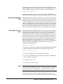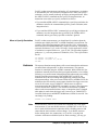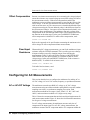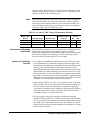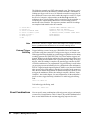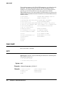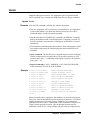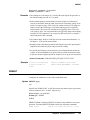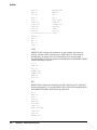
1
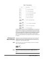
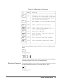
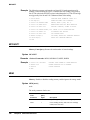
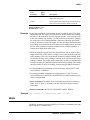
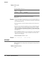
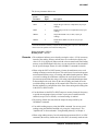
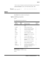
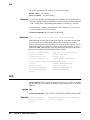
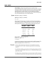
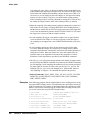
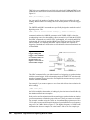
4. Trigger latency
5. Aperture width
6. Aperture jitter
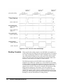
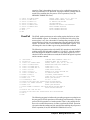
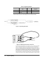
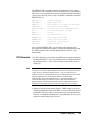
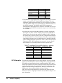
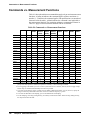
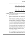
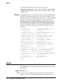
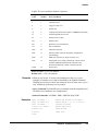
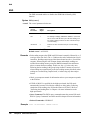
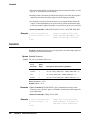
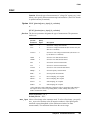
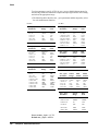
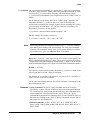
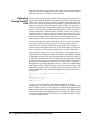
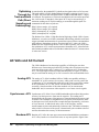
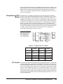
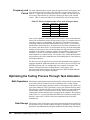
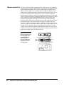
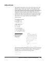
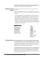
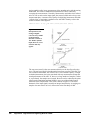
Figure 60. These
digitizing error sources
should be considered in
any measurement.
Amplitude Errors
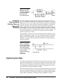
The input signal conditioning section of the 3458A has switches (relays),
attenuators, and amplifiers associated with conditioning and routing the signal for
either the Analog-to-Digital (ADC) or the track-and-hold. Auto zero eliminates
input offset errors but the residual error does propagate. This section is the low
frequency section of the 3458A. Hence, depending on the range, the signal is
routed through a low pass filter (the input amplifier) before being presented to the
ADC.
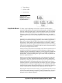
Quantization error is the fundamental, irreducible error associated with the perfect
quantizing of a continuous (analog) signal into a finite number of digital bits.
Hence, the resolution of the ADC has a direct impact on your ability to measure
the input wave form in detail. Some limitations may be overcome by window
amplifiers that will allow the signal's detailed examination in the presence of large
offsets, but the introduction of the amplifier adds error to the measurement that is
not necessary for high resolution ADCs.
Missing code may only manifest itself at high speed. The most common cause of
missing code is dielectric absorption (DA), the polarization of dipoles in the
insulating material surrounding the conductor. Careful design can eliminate this
problem, but DA can cause measurements to have a “memory” of previous
measurements. If sufficient settling time is given to the ADC, the problem falls
below the quantization level.
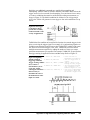
Missing code coupled with quantization error results non-linearity of the ADC.
This occurs in two forms: differential and integral non-linearity. Differential
nonlinearity is the largest step that occurs between successive quantization levels.
Integral non-linearity is the maximum deviation of the linearity curve from a
leastmean-square fit. In general, differential non-linearity may cause significant
measurement error if a low level signal happens to fall on that part of the ADC
transfer function with the differential non-linearity error. Integral non-linearity in
an ADC is generally more detrimental when digitizing full scale signals.
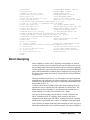
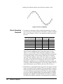
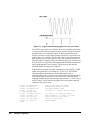
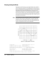
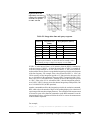
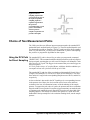
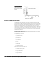
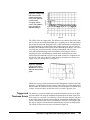
Realize that the transfer function for an ADC is very dependent upon the slew rate
(dV/dt). The transfer function for a static DC input level may appear close to the
ideal. The transfer function under dynamic operating conditions may exhibit
numerous errors as shown in Figure 61.
Appendix E High Resolution Digitizing With the 3458A
359