1
M X - 8 5
DOT MATRIX PRINTER
Operation Manual
P8290062-1
Copyright © 1982 by EPSON
Shinshu Seiki Co., Ltd.
Nagano, Japan
“All rights reserved”
*The contents of this manual are subject to change without notice.
TABLE OF CONTENTS
INTRODUCTlON ........................................................................................................ 1
INSTALLATlON ........................................................................................................... 2
1. Unpacking & Set-up of MX-85 ............................................................................... 2
1.1. Unpacking ............................................................................................................ 2
1.2. Repacking ............................................................................................................. 2
1.3. Contents of carton ............................................................................................... 3
1.4. Operation site.. ..................................................................................................... 4
1.5. Assembly .............................................................................................................. 4
1.6. Opening the printer.. ........................................................................................... 4
1.7. Removal of shipping screws.. ............................................................................. 5
1.8. Removal of the upper case ................................................................................. 5
2. Construction and Location of the MX-85 Component ....................................... 7
3. Setting of DIP swtiches and jumpers ................................................................... 9
3.1. Location of DIP switches and Jumpers.. ............................................................ 9
3.2. Setting DIP switches - SW-A and SW-B.. .......................................................... 9
3.3. Setting of jumpers.. ........................................................................................... 12
4. Power Supply.. ...................................................................................................... 14
5. Cartridge Ribbon Installation .............................................................................. 15
6. Paper Holder Installation ..................................................................................... 16
7. Gap Adjustment ................................................................................................... 18
OPERATION.. ............................................................................................................. 20
1. LF/FF Functions .................................................................................................... 20
2. Self-Test ................................................................................................................. 21
3. On-Line Operation ................................................................................................ 21
4. Theory of Operation ............................................................................................. 22
4.1. Low paper.. ......................................................................................................... 22
4.2. Paper empty.. ..................................................................................................... 23
4.3. 4K memory full.. .................................................................................................
5. Paper Tear-off ........................................................................................................ 24
MAINTENANCE AND PARTS REPLACEMENT ...................................................... 25
Appendix A ASCII/Baudot Code Table.. ................................................................. 27
Appendix B Baudot Code Table .............................................................................. 28
Appendix C Character Fonts.. .................................................................................. 29
- i -
LIST OF FIGURES
Fig. 1
Fig. 2
Fig. 3
Fig. 4
Fig. 5
Fig. 6
Fig. 7
Fig. 8
Fig. 9
Fig. 10
Fig. 11
Fig. 12
Fig. 13
Fig. 14
Fig. 15
Fig. 16
Fig. 17
Fig. 18
Fig. 19
Fig. 20
Fig. 21
Fig. 22
MX-85 Dot Matrix Printer ........................................................................... 1
Contents of Carton.. .................................................................................... 3
Removal of Printer Cover ........................................................................... 4
Removal of Shipping Screws. .................................................................... 5
Removing Manual Paper Feed Knob ........................................................ 6
Loosening All 4 Screws .............................................................................. 6
Removing Wires Connected to Control Panel.. ........................................ 7
Construction of the Printer.. ....................................................................... 8
Location of DIP Switches.. .......................................................................... 9
Setting DIP Switches ................................................................................ 10
Jumpers on the SMCT Board .................................................................. 13
Setting of Power Supply Voltage.. .......................................................... 14
Cartridge Ribbon Setting ......................................................................... 15
Cartridge Ribbon Setting ......................................................................... 16
Examples of Correct and Incorrect Ribbon Setting.. ............................. 16
Loading of Roll Paper (1). ......................................................................... 17
Loading of Roll Paper (2). ......................................................................... 18
Loading of Roll Paper (3) .......................................................................... 18
Cap Adjustment ........................................................................................ 19
20
Switches and Indicators on Control Panel .............................................
Cutting Paper ............................................................................................ 24
Replacement of Print Head ...................................................................... 26
-Ill-
LIST OF TABLES
Table
Table
Table
Table
Table
Table
Table
1
2
3
4
5
6
7
Function and Conditions of DIP Switch B .............................................
Function and Conditions of DIP Switch A .............................................
Baud Rate Selection.. ..............................................................................
ASCII Code Table Selection.. ..................................................................
BAUDOT Code Table Selection.. ............................................................
Function and Conditions of Jumpers ....................................................
25-pin EIA Connector.. ............................................................................
- v -
10
10
11
11
11
12
22
INTRODUCTION
The MX-85 Dot Matrix Printer is a highly versatile communication grade terminal
printer, with the following features:
1. Print Speed: 80 CPS
2. Microprocessor controlled, logic seeking, bidirectional printing
3. Interface: Serial - RS-232C and 20 to 80 mA Current Loop
4. Transmission Code: ASCII and Baudot - 45.5 to 9600 baud
5. Buffer size: 4K Bytes
6. High quality and reliability
7. High density print quality - 9x7 Matrix
8. Operator replaceable, low cost dot head with 100x106 character life
9. Operator replaceable ribbon cartridge with 3x 10 6 character life - Black
10. Standard: Roll Paper Holder
11. Options:
(1) Roll Paper Rewind
(2) Tractor Feed
Fig. 1
MX-85 Dot Matrix Printer
- 1 -
INSTALLATION
1. Unpacking & Set-up of MX-85
Before removing the MX-85 from the carton, check the box for evidence of shipping
damage. If such evidence is present, notify the carrier immediately.
1.1. Unpacking
(1) Open carton.
(2) Remove accessories; ribbon, manual, etc.
(3) Grasp the MX-85 by, its underside and lift straight out with ‘packing material
attached.
(4) Place the printer on a flat surface.
(5) Carefully remove packing material.
(6) Remove the vinyl cover.
1.2. Repacking
Perform in reverse order of above.
NOTE:
Be sure shipping screws and protective sheet for paper sensor are reinstalled. It is
highly recommended that all original material be retained for use in reshipment of the
MX-85.
- 2 -
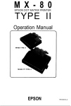
1.3. Contents of carton
The Carton should contain the following:
1. MX-85 Printer
2. Cartridge Ribbon
3. Operation Manual
4. Roll Paper Holder
5. AC Power Cord
6. Filter Circuit Board
If there is any evidence of damage or missing items, contact the vendor from whom
the printer was purchased to report the details.
6. Filter Circuit Board
(Y4252O400000)
4. Roll Paper Holder
3. Operation Manual
1. MX-85 Dot Matrix Pritner
5. AC Power Cord
Fig. 2 Contents
- 3 -
of Carton
1.4. Operation site
1. The MX-85 should be installed on a flat, firm surface with adequate room to the
rear to accommodate the roll paper holder and paper rewind device if so
equipped.
2. Care should be exercised in locating the MX-85 in areas where it will not be
exposed to direct sunlight or where the environment contains grease or dust.
3. The MX-85 should not be located in the vicinity of noise generating equipment or
heat generating equipment.
4. Do not subject the MX-85 to temperatures below 5°C (41°F) or above 35°C (95°F)
during operation. Also avoid sudden changes in temperature and extreme shock.
1.5. Assembly
The following items will be necessary to complete the set-up of the MX-85 Printer.
1. Phillips #2 screwdriver
2. Flat blade screwdriver
3. Soldering iron (if jumper revision is necessary)
1.6. Opening the printer
With the Printer facing you, grasp the cover firmly on the left side with the right hand.
While holding down the left side of the machine with the left hand, pull cover up.
Reinstallation is accomplished by inserting the right side and pushing down on the
left side of the cover.
Fig. 3
Removal of Printer Cover
- 4 -
1.7. Removal of shipping screws
1. Turn the MX-85 upside down, exercising care so the paper release lever is not
bent.
2. Remove the two (2) shipping screws from the lower case.
NOTE:
These shipping screws should be retained for use during reshipment of the
MX-85. They are necessary to prevent damage to the print mechanism which may
be caused by shock or vibration during transportation.
Right Side of the Printer
Lower Case
Shipping Screws
Fig. 4 Removal of Shipping Screws
1.8. Removal of the upper case
In order to check, or change, settings of the internal switches and jumpers, it is
necessary to remove the upper case.
NOTE:
Before proceeding, be sure that the MX-85 is completely disconnected from external
sources. Also, adequately discharge any static electricity which may be present on
your person to prevent damage to any electronic components.
1. Remove the black roller knob on the right side of the printer by pulling straight out,
firmly and steadily.
2. Remove the printer cover, as directed previously, by pulling up on its left side.
- 5 -
Pull out
Fig. 5
Removing Manual Paper Feed Knob
3. Turn the Printer upside down, observing caution with the paper roll release
4. Loosen the four (4) Phillips head screws located in the extreme corners of the
bottom cover.
NOTE:
Placing tape over the holes will prevent accidental loss of the screws when the
Printer is inverted.
5. Turn the Printer right side up. Carefully lift the upper case from the left side. When
the case is partially raised, reach in and pull control panel cable loose. Set the
cover safely aside.
Phillips Head #2 Screwdriver
Fig. 6 Loosening All 4 Screws
- 6 -
Upper Case
Lead Wire
Fig. 7
Removing Wires Connected to Control Panel
2. Construction and Location of the MX-85 Components
At this time, the following main components of the MX-85 Printer and their
respective locations can be observed:
1.
2.
3.
4.
5.
Transformer & Filter Circuit Board
SMDP Board - Top
SMCT Board - Bottom
Printer Mechanism - M-3310
Control Panel
- 7 -
Construction of the Printer
Controller
Transformer &
Filter Circuit Board
Printer Machanism
Control Panel
Transformer & Filter Circuit Board
Controller
Printer Mechanism
MX-85 Dot Matrix Printer
SMDP Board (Driver Circuit Board)
Connector (male and female)
SMCT Board (Control Circuit Board)
Spacer
Controller
Fig. 8
Construction of the Printer
- 8 -
3. Setting of DIP Switches and Jumpers
3.1. Location of DIP switches and jumpers
In order to suit each user’s specific requirements, there are two (2) DIP (Dual In-Line
Pin) switches located on the SMDP Board and sixteen (16) jumpers located on the
SMCT Board.
3.2. Setting DIP switches - SW-A and SW-B
1. With the top cover removed, observe the SMDP Board and locate the two
switches. They are equipped with plastic dust covers which pull off. Remove
them and set aside for later replacement. The switches set to the left are “ON”
and to the right are “OFF”.
2. Tables 1 and 2 outline the function of each switch position. Be sure power is off
when changing the position of any switch.
1) Switch B, the four (4) position switch, is used only to select correct baud rate.
2) Switch A, the eight (8) position switch, is used for code selection, word size,
parity control and line feed control.
The tables also note the factory-set conditions of both switches.
DIP Switch A
Fig. 9
DIP Switch B
Location of DIP Switches
- 9 -
Fig. 10
Table 1
Pin No.
Setting DIP Swtiches
Functions and Conditions of DIP Switch B
Function
Off
On
B1
ON
B2
Baud Rate
B3
See
OFF
Table 3
ON
B4
OFF
Table 2
Functions and Conditions of DIP Switch A
Pin No.
Function
Off
On
A1
Transmission
Code
In ASCII mode
sets Word Structure
In Baudot mode
ASCII
BAUDOT
A 2
A 3
A4
See Table 4
Factory-set
OFF
ON
ON
ON
See Table 5
sets Code Table
A 6
Line Spacing
AUTO FEED XT
A7
Not used
A5
Factory-set
1/3"
1/6"
ON
Invalid
Valid
OFF
OFF
OFF
A8
3. At this time, refer to Table 3 and set the baud rate to your requirements.
-10-
4. Now using Table 2, select your transmission code: ASCII or Baudot.
A. If ASCII is selected, refer to Table 4 for word length setting and parity control.
B. If Baudot is selected, refer to Table 5 for selection of correct Baudot code.
5. Set Line Spacing to desired position.
6. Set Auto Feed if required. This is necessary if the host system does not transmit
line feed control code.
Details of the coding structures are contained in Appendix A for ASCII and Appendix
B for Baudot.
Table 3
Baud Rate Selection
Note: 1 = ON
Table 4 ASCII Code Table Selection
Pin No.
A2
A3
A4
Function
off
On
Factory-set
Data Length
Parity Check
Parity
8 bit
Enable
Even
7 bit
Disable
Odd
ON
ON
ON
Table 5
BAUDOT Code Table Selection
SW A2
ON
SW A3
SW A4
ON
ON
OFF
ON
OFF
OFF
ON
ON
-11-
CODE TABLE
CCITT #2
CCllT #2 AMERICAN
WU/TELEX
3.3. Setting of jumpers
Your application may require the removal or installation of jumpers of the SMCT
Board. Before continuing, consult Table 6 which outlines the function and factory-set
condition of each jumper.
In order to access the SMCT Board it is necessary to remove the SMDP Board. This is
accomplished by:
1. Disconnecting the Mechanism Cable and the AC cable.
2. Removing the six (6) screws on the SMDP Board and the two (2) screws located
in the heat sink on the right side of the board.
3. Lifting the Board from the rear center, in the connector area, to avoid damage.
NOTE:
Any changes in this area should be performed by an experienced technician.
Table 6
Jumper
J1
J2
J3
J4
Function and Conditions of Jumpers
Function
Not used
ON RS-232C
OFF Level
Factory-set
OFF
OFF
Current Loop
ON
Level
Note 1
ON
OFF
Both ON = Polar
Both OFF = Neutral
OFF
Not used
OFF
J7
Not used
OFF
J8
Current Loop (USA Version)
Both are ON when not
ON
ON
ON
J5
J6
J9
J10
J11
J12
J13
J14
J15
J16
OFF
using RTS and CTS
ON when using CTS
OFF
ON when using RTS
OFF
80
60
40
20
OFF
OFF
mA
mA
mA
mA
Current
Current
Current
Current
Loop
Loop
Loop
Loop
Note 2
Note 1: Select either J2 or J3. Do not connect both.
Note 2: Select 1 only. Do not connect 2 or more.
- 12-
OFF
OFF
Jumper
OFF
Jumper
ON
Fig. 11 Jumpers on the SMCT Board
-13-
4. Power Supply
Verify that the power supply is set correctly for your application. Check to see that the
wire connected to the filter board is securely fastened to the correct voltage position.
If it is necessary to change the voltage, use a flat blade screwdriver to loosen the
existing connection and reconnect to the desired voltage. This change will
necessitate a change in the filter circuit board, so your MX-85 supplier should be
notified.
NOTE:
Any changes in this area should be performed by an experienced technician.
Lead Wire
/
Terminal Block
Fig. 12
Setting of Power Supply Voltage
-14-
5. Cartridge Ribbon Installation
1. Position the Printer with the logo facing you.
2. Lift the Printer cover.
3. Be sure the print scale is pushed to the rear, against the platen.
4. Remove the ribbon from its box and turn the knob counterclockwise to remove
any slack.
5. Guide the four (4) tabs on the cartridge into the mechanism side frames.
6. Press down on both ends of the cartridge to firmly seat it.
7. Using a pencil or a similar item, place the ribbon between the front of the head and
the ribbon guide.
8. Wind the ribbon counterclockwise and verify correct positioning.
Fig. 13
Cartridge Ribbon Setting
-15-
Fig. 14 Cartridge Ribbon Setting
-Ribbon
Ribbon Mask
Incorrect
Incorrect
Correct
Fig. 15 Examples of Correct and Incorrect Ribbon Setting
6. Paper Holder Installation
The following steps should be performed with the power off.
1. Set the paper holder behind the MX-85 and locate the rear rubber feet of the
Printer in the forward holes of the paper holder. Failure to do this will result in
severe paper-tracking problems.
-16-
2. Plug jack type connector, which is connected to the “Low Paper” sensor, into
the mating connector located alongside of the 25-pin EIA connector on the rear
of the MX-85.
3. Lift the printer cover and slide the print head to approximately the center of the
printer.
4. Pull the print scale forward and push the paper release to the rear.
5. Mount the roil paper onto the paper holder.
6. Insert the paper into the slot at the rear of the platen on the MX-85.
7. Turn the black knob on the right side of the printer to feed the paper through.
8. Pull the paper release forward and align the paper.
9. Restore the paper release lever to the rear and the print scale to the rear.
Position the plastic tubes on the print scale to retain the paper firmly.
10. Close the printer cover.
MX-85 Dot Matrix Printer
‘Paper Holder
Put into the two holes
Rear View of MX-85
Fig. 16
Loading of Roll Paper (1)
-17-
Roll Paper
Fig. 17
Loading of Rool Paper (2)
Manual Paper Feed Knob
Fig. 18
Loading of Roll Paper (3)
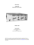
7. Gap Adjustment
It is possible to adjust the gap between the print head and platen to accommodate
various thicknesses of form and print density.
The head adjusting lever is located on the left side frame of the print mechanism.
Move forward to widen gap.
Move rearward to narrow gap.
This lever can also be used to compensate for decreased print density due to ribbon
wear after extended usage.
-18-
Head Adjusting Lever
(Side View)
Position of adjusting lever
Paper
Single-leaf paper
Multi-copy paper sheets
Set the lever to the 4th step.
Set the lever to the 7th step.
Fig. 19 Gap Adjustment
-19-
OPERATION
Power On
1. Plug in AC power cord.
2. Turn on the Printer - switch located to the rear on the right side of the Printer.
1) Buzzer will sound.
2) Print head will return to the left side of the Printer.
3) The “Power”, “Ready” and “On-Line” indicators should be lit on the control
panel. “Paper-Out” indicator will be off.
1. LF/FF Functions
1. Depress the Line Feed (LF) button. Paper will be fed one line at a time while the
switch is held depressed.
2. Depress the Form Feed (FF) button. Paper will be fed either 10 lines (l/S” spacing)
or 5 lines (1/3” spacing). This is preset by the position of DIP Switch A-5.
Depression of this switch will position the last line printed above the tear-off
blade.
NOTE:
Both of these switches will function while On-line. If used while a message is
being received, printing will be interrupted and the LF or FF function will be
performed. Normal printing will resume automatically.
Fig. 20
Switches and Indicators of Control Panel
-20-
2. Self -Test
The MX-85 has a self-test routine programmed into the Controller. It is useful to
check the operation of the print head and the print mechanism (ribbon, motors, belt,
etc.). The input connector is not checked with this test.
1. Be sure there is an adequate supply of paper in the Printer. The test requires about
22 inches.
2. Turn’off power.
3. Turn on power while holding the LF button depressed.
4. The MX-85 will begin printing its test pattern. The LF button can be released after
printing commences.
NOTE:
See Appendix C for Character Fonts.
If any problems are encountered at this point, contact your vendor for correction
before proceeding.
Print sample
.-/0123456789:;<=>?@AB
/0123456789:;<=>?@ABC
0123456789:;<=>?@ABCD
123456789:;<=>?@ABCDE
23456789:;<=>?@ABCDEF
ijklmnopqrstuvwxyz{
jklmnopqrstuvwxyz{:
klmnopqrstuvwxyz{:}
1mnopqrstuvwxyz{:}~
mnopqrstuvwxyz{:}~
3. On-Line Operation
Connection to your host system is through the 25-pin EIA connector located on the
left rear of the MX-85. The pin assignments are noted in Table 8. It is recommended
that all interface cables be as short as possible to minimize noise injection.
-21-
Table 7
I
Pin No.
1
2
3
4
5
7
11
20
23
25
25-pin EIA Connector
Signal Name
Chassis Ground
TXD
RXD
RTS
CTS
Signal Ground
Reverse Channel (REV)
Data Term Rdy (DTR)
TTY-RXD Return
TTY-RXD
Current
Loop Input
4. Theory of Operation
The data received by the MX-85 is stored in the 4K Byte Memory. Printing is initiated
by the following means:
1. Receipt of the Carriage Return (CR) or Line Feed (LF) Control codes.
2. An excess of 80 characters (1 line) in the print buffer.
3. A transmission gap in excess of two (2) seconds, provided there are printable
characters stored in the buffer.
The MX-85 will continue to receive data and store it in the buffer memory while
printing.
There are some conditions which will interfere with the ability of the MX-85 to
receive and/or print data. These are:
1. Paper Low
2. Paper Empty
3. 4K Memory Full
4.1. Low paper
The low paper sensor is mounted on the paper holder. It is activated when
approximately 7 meters (22’) of paper is remaining. This should be adequate to print
any message being transmitted at the time of activation. When the sensor is
activated, the following conditions will take place:
Status - DTR pin 20 Mark (-V)
Data Entry - Available until buffer full
Indicators - “Paper Out” ON
“Ready” OFF
Buzzer - Sounds for 20 seconds
Printing - Unaffected
NOTE:
Buzzer will stop upon depression of LF or FF button.
-22-
4.2. Paper empty
The paper empty switch located beneath the platen will activate when the paper runs
out. When activated, the following conditions will take place:
Status - DTR pin 20 = Mark (-V)
Rev Chan pin 11 = Mark (-V)
Data Entry - Available until buffer full
Indicators - “Paper Out” ON
"Ready” OFF
Buzzer - Sounds for 20 seconds
Printing - Disabled
NOTE:
Buzzer will stop upon depression of LF or FF button.
Both the paper empty and the low paper conditions call for replacement of the paper
roll. This should be done with the power on to avoid losing any data. Upon completion
of paper loading, the “On-Line” button should be depressed. This will activate
printing if there are any printable characters stored in the memory. The “Paper-Out”
indicator w&be extinguished and the “Ready” indicator illuminated if the MX-85 is
not in a memory full condition.
4.3. 4K memory full
When the buffer memory reaches 3,996 bytes, the following conditions will take
place:
Status - DTR pin 20 = Mark (-V)
Rev Chan pin 11 = Mark (-V)
Data Entry - Disabled
Indicators - “Ready” OFF
Printing - Enabled
As soon as 1 K bytes of memory is made available, all of the above conditions will
revert to normal.
-23-
5. Paper Tear-Off
1. To tear off the last message printed, depress the FF button to position the paper.
2. Hold down the printer cover while tearing the paper.
3. Check to see that the paper is against the platen and that the paper has not
shifted. Reposition if necessary.
Tear off the Paper
Fig. 21
Cutting Paper
- 2 4 -
MAINTENANCE AND PARTS
REPLACEMENT
Preventative Maintenance of the MX-85 consists mainly of cleaning.
1. Paper dust and particles should be cleared away with a soft brush.
2. The exterior of the Printer can be cleaned with a mild detergent and water
solution.
3. The interior of the Printer can be cleaned with denatured alcohol.
The only user replaceable items are the cartridge ribbon and the print head. Cartridge
ribbon replacement is covered in a previous section of this manual.
Print Head replacement
CAUTION:
The print head runs very hot under normal operating conditions. Allow time for it to
cool before attempting replacement.
1. Remove the printer cover and cartridge ribbon.
2. Turn the head locking lever clockwise and lift the print head straight up.
3. Disconnect the cable carefully by pulling the plastic tab under the cable while
holding the terminal board.
4. Install the new print head onto the carriage assembly and turn the head locking
lever counterclockwise.
5. Carefully install the head cable into the connector assembly.
6. Replace the cartridge ribbon and printer cover.
7. Run Self-Test.
-25-
Print Head Unit
Terminal Board
Head Lock Lever
Head Connector
Be sure to hold this connectar firmly to pull the
head cable out straight.
Carriage A&embly
(Side View)
*Take hold of the cable at
the point indicated by
arrows
and apply
force in either of the
directions indicated by
arrow
to push in or
pull out the head cable.
Fig. 22
Replacement of Print Head
-26-
Appendix A ASCII Code Table
b1 (low order bit) is normally transmitted first.
-27-
Appendix B Baudot Code Table
-28-
Appendix C Character Fonts
(Hex. Code)
AF
NOTE: Numbers represent Hex.
-29-
NOTE: Numbers represent Hex. Code.
-30-
FEDERAL COMMUNICATIONS COMMISSION
RADIO FREQUENCY INTERFERENCE
STATEMENT
“This equipment generates and uses radio frequency energy and if not installed
and used properly, that is, in strict accordance with the manufacturer’s
instructions, may cause interference to radio and tele vision reception. It has been
type tested and found to comply with the limits for a Class B computing device in
accordance with the specifi cations in Subpart J of Part 15 of FCC Rules, which are
designed to provide reasonable protection against such interference in a residen
tial installation. However, there is no guarantee that interference will not occur in a
particular installation. If this equipment does cause interference to radio or
television reception, which can be determined by turning the equipment off and
on, the user is encouraged to try to correct the interference by one or more of the
following measures:
. . . . . ..reorient the receiving antenna
. . . . . . .relocate the computer with respect to the receiver
. . . . . ..move the computer away from the receiver
. . . . . ..plug the computer into a different outlet so that computer and receiver are
on different branch circuits.
If necessary, the user should consult the dealer or an experienced radio/television
technician for additional suggestions.
The user may find the following booklet prepared by the Federal Communications
Commission helpful: “How to Identify and Resolve Radio-TV Interference
Problems. ”
This booklet is available from the US Government Printing Office, Washington,
D.C., 20402, Stock No. 004-000-00345-4.”
This statement will be applied only for the printers marketed in the U.S.A.