1
Snap Server™ 700i Series
User’s Guide
for Adaptec OnTarget™-Powered Snap Servers
COPYRIGHT
Copyright © 2008, Adaptec, Inc. All rights reserved worldwide.
Information in this document is subject to change without notice and does not represent a
commitment on the part of Adaptec or any of its subsidiaries. The software described in this document
is furnished under a license agreement. The software may be used only in accordance with the terms
of the license agreement. It is against the law to copy the software on any medium. No part of this
manual may be reproduced or transmitted in any form or by any means, electronic or mechanical,
including photocopying and recording, for any purpose without the express written permission of
Adaptec, Inc.
TRADEMARKS
Adaptec, the Adaptec logo, Adaptec OnTarget, Storage Manager, Snap Server, the Snap Server logo,
GuardianOS, SnapOS, and Snap Disk are trademarks or registered trademarks of Adaptec, Inc. in the
U.S.A. and other countries.
Products mentioned herein are for identification purposes only and may be registered trademarks or
trademarks of their respective companies. Microsoft, Windows, Windows Vista, Internet Explorer,
and Active Directory are registered trademarks of Microsoft Corporation. Java and Solaris, are
registered trademarks of Sun Microsystems, Inc. Netscape is a registered trademark of Netscape
Communications Corp. AppleShare, AppleTalk, Macintosh, and MacOS are registered trademarks of
Apple Computer. BakBone and NetVault are trademarks of BakBone Software. AIX is a registered
trademark of IBM Corporation. OpenView and HP-UX are trademarks or registered trademarks of
Hewlett-Packard Company. BrightStor, Unicenter TNG, ARCserve, eTrust, and Unicenter are
trademarks or registered trademarks of Computer Associates, Inc. Smart UPS and APC are registered
trademarks of American Power Conversion Corporation. UNIX is a registered trademark of The Open
Group. XFS is a trademark of Silicon Graphics, Inc. Backup Exec, VERITAS NetBackup
BusinessServer, and VERITAS NetBackup DataCenter are trademarks or registered trademarks of
VERITAS Software Corporation. Legato NetWorker is a trademark of Legato Systems, Inc. Linux is a
registered trademark of Linus Torvalds. SCO Open Server and UnixWare are trademarks of the SCO
Group. StorAssure is a registered trademark of Adaptec, Inc. All other brand names or trademarks are
the property of their respective owners.
REVISIONS
Adaptec, Inc. provides this publication “as is” without warranty of any kind, either express or
implied, including but not limited to the implied warranties of merchantability or fitness for a
particular purpose. Adaptec and its subsidiaries reserve the right to revise this publication and to
make changes in the content hereof without the obligation of Adaptec to notify any person of such
revision or changes.
ADAPTEC, INC. SOFTWARE LICENSE AGREEMENT
CAREFULLY READ THE FOLLOWING TERMS AND CONDITIONS. BY YOUR USE OF THE SOFTWARE
INCLUDED WITH THIS PRODUCT, YOU AGREE TO BE BOUND BY THESE TERMS, CONDITIONS, AND
REQUIREMENTS. IF YOU DO NOT AGREE TO THE LICENSE TERMS, CONDITIONS, AND REQUIREMENTS
APPLICABLE TO THE SOFTWARE, YOU ARE NOT PERMITTED TO USE THE SOFTWARE AND MAY
RETURN THE ENTIRE UNUSED HARDWARE PRODUCT FOR A FULL REFUND. THESE TERMS,
CONDITIONS, AND REQUIREMENTS DO NOT APPLY TO ANY OPENSOURCE SOFTWARE, WHICH MAY
BE DELIVERED TOGETHER WITH THE ADAPTEC PRODUCTS, EXCEPT FOR THE PROVISIONS SET FORTH
IN SECTION 7 AND 9 BELOW.
In return for acquiring a license to use the Adaptec software ("Software") and the related documentation, you
agree to the following terms and conditions:
1. License. This Agreement grants you, the Licensee, a license to:
• Use the Software on a single computer system or on multiple workstations, systems and servers which
incorporate an Adaptec Hardware product and may be accessed by multiple users from multiple locations.
You may make as many installations of the Software as needed, but must restrict such installation only to
systems, workstations or servers using an Adaptec hardware product.
• Make one copy of the Software in machine readable form solely for back-up purposes provided you reproduce Adaptec’s copyright notice and any proprietary legends.
2. Restrictions. You may not distribute copies of the Software to others. You may not post or otherwise make
available the Software, or any portion thereof, in any form, on the Internet. You may not use the software in a
computer service business, including in time sharing applications. The Software contains trade secrets and in
order to protect them you may not decompile, reverse engineer, disassemble, or otherwise reduce the Software
to a human perceivable form. YOU MAY NOT MODIFY, ADAPT, TRANSLATE, RENT, LEASE, LOAN,
RESELL FOR PROFIT, DISTRIBUTE OR CREATE DERIVATIVE WORKS BASED UPON THE SOFTWARE OR
ANY PART THEREOF.
3. Ownership. As Licensee, You own the media upon which the Software is recorded or fixed, but Adaptec and
its licensors retain title, ownership and intellectual property rights of the Software recorded on the original
media and all subsequent copies of the Software, regardless of the form or media in which or on which the
original and other copies may exist. This license is not a sale of the Software or any copy. The Software is
copyrighted by, proprietary to and a trade secret of Adaptec or its licensors. The Software is protected by the
copyright laws of the United States and international copyright treaties.
4. Termination. This license is effective until terminated. This license will terminate automatically without notice
if you fail to comply with any of the provisions. You may terminate the license at any time by destroying the
Software (including the related documentation) together with all copies or modifications in any form. Upon
termination you shall destroy all copies of the Software (including the related documentation), together with
any partial copies.
5. Limited Warranty. Adaptec and its Licensors warrant only that the media upon which the Software is
furnished will be free from defects in material or workmanship under normal use and service for a period of
thirty (30) days from the date of delivery to you. THE FOREGOING WARRANTY EXPRESSLY EXCLUDES
ANY OPEN SOURCE SOFTWARE PROVIDED TO YOU WITH THE ADAPTEC SOFTWARE. ADAPTEC
AND ITS LICENSORS DO NOT AND CANNOT WARRANT THE PERFORMANCE OR RESULTS YOU MAY
OBTAIN BY USING THE SOFTWARE, OPEN SOURCE SOFTWARE OR DOCUMENTATION. EXCEPT FOR
THE FOREGOING LIMITED WARRANTY, ADAPTEC AND ITS LICENSORS MAKE NO WARRANTIES,
EXPRESSED OR IMPLIED, INCLUDING, BUT NOT LIMITED, AS TO NON-INFRINGEMENT OF THIRD
PARTY RIGHTS, MERCHANTABILITY OR FITNESS FOR A PARTICULAR PURPOSE. Some states do not
allow the exclusion of implied warranties or limitations on how long an implied warranty may last, so the
above limitations may not apply to you. This warranty gives you specific legal rights and you may also have
other rights which vary from state to state.
The entire liability of Adaptec and its licensors, and your exclusive remedy for a breach of this warranty, shall
be the replacement of any media not meeting the above limited warranty which is returned to Adaptec; or if
Adaptec or its distributor is unable to deliver replacement media which is free from defects in materials or
workmanship, you may terminate this Agreement by returning the Software and your money will be
refunded.
THE FOREGOING STATES THE SOLE AND EXCLUSIVE REMEDIES ADAPTEC AND ITS LICENSORS
WILL PROVIDE FOR BREACH OF WARRANTY.
6. Limitation of Liability. IN NO EVENT WILL ADAPTEC OR ITS LICENSORS BE LIABLE TO YOU FOR ANY
INCIDENTAL, CONSEQUENTIAL OR INDIRECT DAMAGES, INCLUDING ANY LOST PROFITS, LOST
SAVINGS, OR LOSS OF DATA, EVEN IF ADAPTEC OR A LICENSOR HAS BEEN ADVISED OF THE
POSSIBILITY OF SUCH DAMAGES, OR FOR ANY CLAIM BY ANY OTHER PARTY. IN NO EVENT WILL
ADAPTEC BE LIABLE UNDER THIS AGREEMENT FOR ANY AMOUNT IN EXCESS OF THE LICENSE
FEES YOU PAID FOR THE SOFTWARE OR, IF THE SOFTWARE WAS FREE, IN AN AMOUNT IN EXCESS
OF THE AMOUNT PAID BY YOU FOR THE HARDWARE SOLD IN CONJUNCTION WITH THE
SOFTWARE. Some states do not allow the exclusion or limitation of special, incidental, or consequential
damages, so the above limitation or exclusion may not apply to you.
7. Export. You acknowledge that the laws and regulations of the United States restrict the export and re-export of
the Software and/or the Open Source Software. Further, you agree that you will not export or re-export the
Software and/or the Open Source Software or media in any form without the appropriate United States and
foreign government approval.
8. U.S. Government Restricted Rights. If the Software is acquired under the terms of a GSA contract, use,
reproduction or disclosure is subject to the restrictions set forth in the applicable ADP Schedule contract. If the
Software is acquired under the terms of a DoD or civilian agency contract, use, duplication or disclosure by the
Government is subject to the restrictions of this license in accordance with 48 C.F.R. 12.212 of the Federal
Acquisition Regulations and its successors and 48 C.F.R. 227.7202-1 of the DoD FAR Supplement and its
successors.
9. Open Source Software. Certain programs distributed in conjunction with the Software may be distributed
subject to third party licensing terms, including without limitation, the GNU General Public (“GPL”) License
available at: http://www.gnu.org/licenses/gpl.txt or by writing to the Free Software Foundation, Inc., 59
Temple Place, Suite 330, Boston, MA 02111-1307 USA. The source code for the programs licensed under the
GPL is available to You, for a period of three (3) years from the date of first commercial distribution of the
Software, upon request by contacting Adaptec in writing at 691 South Milpitas Boulevard, Milpitas, California
95035, ATTN: Legal Department, Open Source Request. Adaptec will only charge you the actual cost of the
medium used to distribute the source code for these programs and the cost of shipping. More details regarding
the open source software and the applicable open source licenses are available in the README files.
10. Export Compliance. Each party agrees that the Software is subject to the U.S. Export Administration Act and
Export Administration Regulations, as well as applicable import and export regulations of the countries in
which each party transacts business. Each party shall comply with such laws and regulations, as well as all
other laws and regulations applicable to the Software. Each party agrees that it will not export, re-export,
transfer or divert any of the Software to any country for which United States' laws or regulations require an
export license or other governmental approval, without first obtaining such license or approval, nor will each
party export, re-export, transfer or divert any of the Software to any restricted place or party in accordance
with U.S. export regulations.
11. General. You agree this is the complete agreement concerning this license. In order to amend this license, a
writing executed by both parties is required. You assume full responsibility for the legal and responsible use of
the Software. This license shall be governed by California law as such law applies to agreements between
California residents entered into and to be performed within California, except as governed by Federal law.
Should any provision of this license be declared unenforceable in any jurisdiction, then such provision shall be
deemed to be severable from this license and shall not affect the remainder hereof. All rights in the Software
not specifically granted in this license are reserved by Adaptec.
Should you have any questions concerning this license, contact:
Adaptec, Inc.
Legal Department
691 South Milpitas Boulevard
Milpitas, California 95035
(408) 957-1718
Contents
Preface ..................................................................................... 7
Chapter 1 About this Guide ................................................................................ 7
What’s Included in this User’s Guide .......................................................8
What You Need to Know Before You Begin .............................................8
Terminology Used in this Guide ..............................................................8
Service and Technical Support ................................................................9
Notes and Cautions .............................................................................10
Finding More Information ....................................................................10
Chapter 2 Planning Your IP SAN ....................................................................... 13
Introduction to Adaptec Storage Manager for iSCSI Storage ...................13
Understanding Adaptec Storage Manager’s Main Components ...............16
Planning Your IP SAN Configuration and Setup .....................................18
Sample IP SAN Configurations .............................................................18
Building an IP SAN Without a DHCP Server...........................................24
System Requirements............................................................................25
Chapter 3 Installing Adaptec Storage Manager.................................................. 27
Before You Begin .................................................................................27
Installing on Windows..........................................................................27
Installing on Linux ................................................................................30
Using Adaptec Storage Manager with a Firewall....................................32
Chapter 4 Setting Up Your iSCSI Storage Appliance and IP SAN ......................... 33
An Overview of the Setup Process .........................................................33
Before You Begin .................................................................................34
Snap Server 700i User’s Guide
1
Step 1: Starting Adaptec Storage Manager............................................35
Step 2: Configuring the iSCSI Storage Appliance ...................................36
Step 3: Creating RAID Pools .................................................................38
Step 4: Provisioning Storage to Your Systems .........................................40
Step 5: Continuing to Build Your IP SAN................................................46
Step 6: Logging in to the iSCSI Storage .................................................46
Step 7: Registering Your iSCSI Storage Appliance ..................................47
Beginning to Use Your IP SAN ..............................................................47
Chapter 5 Getting to Know Adaptec Storage Manager....................................... 51
Working in Adaptec Storage Manager..................................................51
Navigating the Main Window ..............................................................52
Checking System Status from the Main Window .....................................59
Getting Help........................................................................................60
Uninstalling Adaptec Storage Manager .................................................60
Chapter 6 Protecting Your Data......................................................................... 61
Protecting Your Data with Hot Spares ....................................................61
Backing Up Your Data with Snapshots ...................................................63
Backing Up Your Data with Mirrored Volumes .......................................72
Backing Up Your Data with Replicas......................................................78
Chapter 7 Controlling Access to Your IP SAN ..................................................... 83
Limiting Discovery of iSCSI Targets with Discovery Control Lists................83
Controlling Access to Your IP SAN with Authentication ...........................85
Limiting User Access to Your IP SAN with the Security Manager ..............86
Chapter 8 Modifying Your iSCSI Storage ........................................................... 91
Adding More Components to Your IP SAN ............................................91
Creating and Modifying Pools...............................................................94
Creating and Modifying Volumes........................................................102
2
Snap Server 700i User’s Guide
Creating and Modifying Logical Devices.............................................. 104
Chapter 9 Maintaining Your iSCSI Storage Appliance .......................................107
Configuring the Uninterruptible Power Supply (UPS) Monitor ................ 107
Blinking Appliances, Enclosures, and Disk Drives ................................. 109
Shutting Down the iSCSI Storage Appliance ........................................ 110
Shutting Down and Restarting the iSCSI Storage Appliance .................. 110
Changing the iSCSI Storage Appliance’s Settings................................. 110
Updating the Adaptec OnTarget Operating System.............................. 111
Chapter 10 Monitoring Status and Activity .......................................................115
Monitoring Jobs in Progress ............................................................... 115
Viewing Status and Activity ................................................................ 118
Using Status and Drive Light Behavior to Monitor Components .............. 121
Notifying Users By Email About Status and Activity .............................. 126
Notifying Users By SNMP Trap About Status and Activity ..................... 130
Monitoring Your GuardianOS-Powered Snap Servers .......................... 132
Chapter 11 Updating and Customizing Adaptec Storage Manager ....................139
Updating Adaptec Storage Manager .................................................. 139
Customizing Adaptec Storage Manager.............................................. 139
Creating and Working with Display Groups ........................................ 141
Chapter 12 Solving Problems...........................................................................143
General Troubleshooting Tips ............................................................. 143
Troubleshooting Questions and Answers ............................................. 144
Silencing an Alarm ............................................................................ 148
Identifying Failed or Failing Components............................................. 148
Hot Swapping Disk Drives .................................................................. 150
Recovering from a Disk Drive Failure .................................................. 150
Rebuilding Pools................................................................................ 152
Contents
3
Recovering Snapshots After a Pool Capacity Failure .............................154
Using the Reset Button to Perform a Limited Reset of the Appliance.........154
Recovering from an iSCSI Storage Appliance Failure ............................155
Appendix A Configuring iSCSI Initiators .......................................................... 163
Configuring iSNS with the CLI.............................................................163
iSCSI Configuration for Microsoft Windows .........................................165
iSCSI Configuration for Red Hat or SUSE Linux ....................................173
iSCSI Configuration for VMware .........................................................176
Appendix B Using the CLI................................................................................ 179
Accessing the CLI ...............................................................................179
Access Levels and Passwords ..............................................................180
Using the Wizard to Configure Your iSCSI Storage Appliance...............181
About CLI Commands and Parameters.................................................183
About the Command Format in This Guide ..........................................184
Command Completion .......................................................................184
Command Line Editing .......................................................................185
Viewing Long Reports.........................................................................186
The CLI and Adaptec Storage Manager ...............................................186
Getting Help......................................................................................187
Appendix C Your Snap Server 700i Series....................................................... 189
Hardware Components ......................................................................189
Product Descriptions...........................................................................190
Identifying the Ethernet Ports ...............................................................191
Basic Hardware Shipped with Snap Server 700i Series.........................192
Snap Server and Expansion Array Hardware Checklists .......................194
4
Snap Server 700i User’s Guide
Snap Server and Expansion Array Hardware Specifications ................. 198
Safety Precautions ............................................................................. 200
Appendix D RAID Quick Reference...................................................................201
Comparing RAID Levels ..................................................................... 201
Selecting a RAID Level by Size of Pool................................................. 201
Expanding Pool Capacity ................................................................... 202
Changing from One RAID Level to Another.......................................... 202
Appendix E Completing a Silent Windows Installation ......................................203
Completing a Silent Installation........................................................... 203
Available Properties and Values ......................................................... 204
Example Command Line Installations................................................... 206
Appendix F OS Support Quick Reference .........................................................209
iSCSI Initiator Support by OS ............................................................. 210
Adaptec Storage Manager Feature Support by OS ............................. 211
Glossary ................................................................................213
Index.....................................................................................221
Contents
5
6
Snap Server 700i User’s Guide
Preface
About this Guide
When connected and configured as an iSCSI Storage Appliance, your Snap Server
700i Series contains storage space that can be shared by systems in an IP Storage
Area Network (IP SAN).
Three software components are included with the Snap Server 700i Series:
• Adaptec OnTarget™ operating system: The Adaptec OnTarget software runs on an
embedded version of the Linux operating system in the Snap Server 700i Series
chassis. The Adaptec OnTarget software is primarily concerned with virtualizing
physical disks as iSCSI volumes; however, it can also be used to create or manage
the iSCSI storage through the Command Line Interface (CLI). It should be
updated whenever the Adaptec Storage Manager software is updated. Refer to
“Maintaining Your iSCSI Storage Appliance” on page 107 for instructions on
updating the Adaptec OnTarget software.
• Adaptec Storage Manager: Use Adaptec Storage Manager (included on the
Adaptec OnTarget User CD) to create and manage your iSCSI storage. You can
also use Adaptec Storage Manager to monitor any GuardianOS-powered Snap
Servers on your network, as well as any Adaptec direct attached storage (DAS)
RAID controllers. Adaptec Storage Manager is installed on workstations and
consists of three modules:
• GUI and agent: The ASM GUI. Install it on laptops or workstations to access the
ASM Management Service and manage storage remotely.
• Management Service: Install it along with the GUI to add and manage your
iSCSI Storage Appliances.
• Windows Support: This includes additional modules for Windows 2003
systems that support automatic provisioning, mirroring, snapshots, and
storage management using third-party VDS-aware tools.
• Command Line Interface: The Command Line Interface (CLI) software allows you
to monitor and manage the iSCSI Storage Appliance. Use the CLI to create and
manage iSCSI targets that appear as local disk storage on your server and use the
event logging features to monitor the entire system.
Note In addition to the software components supplied with the Snap Server 700i
Series, you must also have software to support your iSCSI Initiator, and when
running on Microsoft Windows operating systems, Microsoft iSCSI Initiator must
be installed. See “Configuring iSCSI Initiators” on page 163 for more information.
Snap Server 700i Series User’s Guide
7
What’s Included in this User’s Guide
This User’s Guide describes how to use Adaptec Storage Manager to configure your
iSCSI Storage Appliance and create an IP SAN, modify and monitor iSCSI storage,
maintain your iSCSI Storage Appliance, and monitor any GuardianOS-powered
Snap Servers on your network. It also provides instructions for installing and
configuring iSCSI initiators in the systems that will be accessing iSCSI storage.
For advanced users, this Guide also provides detailed instructions for using the iSCSI
Storage Appliance’s CLI (see page 179).
Additionally, this Guide describes the hardware features and specifications for your
Snap Server 700i Series and S50 expansion array (see page 189).
Note For more information about using Adaptec Storage Manager with Adaptec
direct attached storage, refer to the Adaptec Storage Manager User’s Guide for Direct
Attached Storage on the installation CD that came with your Adaptec DAS RAID
controller.
What You Need to Know Before You Begin
This Guide is written for system or network administrators who want to create an IP
SAN. Advanced knowledge of storage networks is not required, but you should be
familiar with computer hardware, data storage, and network administration
terminology and tasks, and have knowledge of Internet SCSI (iSCSI) and
Redundant Array of Independent Disks (RAID) technology.
Terminology Used in this Guide
In this Guide, these terms will be used to differentiate between your Snap Server
700i Series and any other Snap Servers you may be monitoring with Adaptec
Storage Manager:
• iSCSI Storage Appliance—Snap Server 700i Series or Adaptec OnTarget-powered
Snap Server
• GuardianOS-powered Snap Server—Non-700i Series Snap Server
In this Guide, when the term ‘Adaptec Storage Manager’ is used, it refers to the
graphical user interface (GUI)—the window that opens on your monitor when you
run the software.
For efficiency, the term “component” or “components” is used when referring
generically to the physical and virtual parts of your IP SAN, such as systems, disk
drives, pools, and logical devices.
Many of the terms and concepts referred to in this Guide are known to computer
users by multiple names. In this Guide, this terminology is used:
• Disk drive (also known as hard disk, hard drive, or hard disk drive)
• Logical device (also known as logical drive)
• System (also known as a workstation or machine)
• Enclosure (also known as a JBOD, disk enclosure, or storage enclosure)
Service and Technical Support
For an immediate response to a service inquiry, use our Expert Knowledge Base
System at http://ask.adaptec.com/scripts/adaptec_tic.cfg/php.exe/enduser/
home.php. Simply type in your question to view a list of possible resolutions to
known issues. However, if none of the listed topics resolves your inquiry, you can
forward the question to our Technical Support department who will then e-mail
you with a response. To obtain additional service or technical support for your Snap
Server 700i Series, call 408-934-7274.
Additional Resources
Resource
Description
Knowledge Base
Search for solutions to specific issues by clicking the Knowledge
Base link on the Adaptec support page:
http://ask.adaptec.com/scripts/adaptec_tic.cfg/php.exe/
enduser/home.php
Hardware
Components
Purchase additional hardware components from authorized Adaptec
resellers. To locate a reseller in your area, select the Where to Buy
tab on the Adaptec home page:
http://www.snapserver.com
Field Service
Documents
Find a list of the hardware components available for your Snap
Server 700i Series or S50 expansion array and instructions for
installing or replacing components by going to the Snap Server
support page, clicking Documentation Center and then navigating to
the server or expansion array model:
http://www.snapserver.com/snap/en-US/Support/
Notes and Cautions
Conventions used to call out useful or important information are described below:
Note A note presents time-saving shortcuts related to the main topic.
Caution A caution alerts you to potential hardware or software issues or hazards in
the configuration or operation of Snap Server 700i Series. Consider cautions
carefully before proceeding with any operation.
Typographical Conventions
Convention
Usage
Italic
• Emphasis
• The introduction of new terms
• File names
• Settings you select or enter in the Administration Tool
Arial Bold
Navigational paths, command buttons, and navigational
links.
Arial
• Text you type directly into a text field, a command line,
or a Web page
• Buttons on a keyboard
Arial Italic
A variable for which you must substitute a value
Arial
Commands you enter in a command-line interface
Finding More Information
Product documentation related to the Adaptec OnTarget-powered Snap Server 700i
Series and SANbloc S50 expansion array are listed below. The current versions of all
these documents are always available from http://www.snapserver.com/snap/enUS/Support.
Source and Location
Content
700i Series Quick Start Guide
Details package contents, identifies server
hardware components, and provides complete
instructions for installing the server to a rack,
connecting the server to the network, and
configuring the iSCSI Storage Appliance. Also
contains the EULA and warranty.
Product Packaging and Web
SANbloc S50 Quick Install Guide
Product Package and Web
Snap Server 700i Series
User Guide
User CD and Web
Adaptec Storage Manager Online
Help
Readme.txt
User CD
Field Service Documentation
Service CD and Web
Details package contents, identifies expansion
array hardware components, and provides
complete instructions for installing the SANbloc S50
to a rack and connecting it to a Snap Server.
Provides an overview of the configuration and
maintenance of the Snap Server 700i Series, gives
detailed instructions on using Adaptec Storage
Manager to configure and manage your iSCSI
storage, and provides hardware specifications for
the Snap Server 700i Series and the SANbloc S50
expansion array.
Contains late-breaking information, corrections, and
known issues concerning the Snap Server 700i
Series.
Provides detailed instructions for the replacement of
disk drives, adapter cards, power assemblies, slide
rails, and other hardware components.
Chapter 2
Planning Your IP SAN
This chapter introduces the Adaptec Storage Manager software and provides a guide
to planning your IP SAN configuration and setup.
It also provides important instructions for using your iSCSI Storage Appliance on a
network without a DHCP server.
Introduction to Adaptec Storage Manager for iSCSI
Storage
Adaptec Storage Manager is a software application that helps you build and
manage storage for your online data. From the ‘one-view’ user interface, you can
use Adaptec Storage Manager to:
• Create, monitor, and manage iSCSI storage
• View and monitor any GuardianOS-powered Snap Servers on your network
• Create, monitor, and manage direct attached storage
This Guide describes how to use Adaptec Storage Manager to set up, monitor, and
manage iSCSI storage, and monitor GuardianOS-powered Snap Servers.
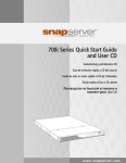
DAS
iSCSI
LAN
Manage iSCSI storage
(described in this Guide)
System running Adaptec
Storage Manager GUI
Manage direct attached storage
You can use Adaptec Storage Manager to:
• Combine physical disk drives into virtual storage pools (pools) that are protected
with RAID, and increase the capacity or change the RAID level of existing pools.
• Protect and control access to your IP SAN and data.
• Monitor your IP SAN, using activity notifications and the event viewer in the
main window.
• Maintain your iSCSI Storage Appliances.
• Provision storage to the systems on your network automatically (supported on
some operating systems only) or manually.
• Create application-consistent snapshots of provisioned storage, for extra data
protection (supported on some operating systems only).
• Create synchronous mirrors of provisioned storage, for an extra layer of data
protection and increased data availability (supported on some operating systems
only).
Note Synchronous mirroring requires a minimum of two iSCSI Storage
Appliances.
Adaptec Storage Manager provides wizards to guide you through many of these
tasks.
iSCSI Storage Feature Support
Support for Adaptec Storage Manager’s iSCSI storage features varies by operating
system (OS)—depending on which OS is running on an individual system, either
the full set or a subset of Adaptec Storage Manager iSCSI storage features is
available on that system.
Additionally, the storage provisioning process may be automatic or manual for an
individual system depending on which OS is installed.
Systems running Windows 2003 to which you provision storage are referred to in
Adaptec Storage Manager as iSCSI Storage Hosts.
The table on page 15 lists the features available for a system running one of the
supported OSs.
On a system running these OSs... You can...
Microsoft® Windows Data Center 2003
Windows
Server®
2003 (all versions)
Windows Small Business Server 2003
Install the GUI to manage your IP SAN from
a centralized location
Create application-consistent snapshots of
storage provisioned to the system
Create synchronous mirrors (with automatic
failover) of storage provisioned to the system
Adaptec Multipath Input Output (MPIO)
Full Feature Set
Provision storage to the system
automatically
Device Specific Module (DSM) Driver
Use Adaptec Storage Manager with
Microsoft Virtual Disk Services (VDS)
Windows® XP (all versions)
Install the GUI to manage your IP SAN from
a centralized location
Red Hat Enterprise Linux 5
Provision storage to the system manually
SUSE Linux Enterprise Server 9 SP3
Adaptec Multipath Input Output (MPIO)
Device Specific Module (DSM) Driver
VMware® ESX Server 3.x.x
Provision storage to the system manually
Note: No other iSCSI storage feature is
currently supported by VMware.
Feature Subsets
Red Hat® Enterprise Linux 4 U5
Notes For simplicity, in this Guide, Windows Server 2003 (all versions), Windows
Small Business Server 2003, and Windows Data Center 2003 operating systems are
known collectively as ‘Windows 2003’.
Refer to the Adaptec Web site at www.adaptec.com for the most up-to-date list of
supported OSs.
Understanding Adaptec Storage Manager’s Main
Components
During installation, you have the option to install up to three main components of
Adaptec Storage Manager on a system:
• The GUI and Agent
• The Management Service
• Windows Support (see page 17)
Ensure that you understand the role of these components before continuing.
Note Component support varies by operating system. See page 211 for more
information.
The GUI and the Agent
The GUI (or graphical user interface) is the window that opens when you run Adaptec
Storage Manager. You build, monitor, and modify your IP SAN from the GUI.
The Adaptec Storage Manager Agent is a software component that runs in the
background and communicates status and other information about any Adaptec
direct attached storage on a system. The Agent requires no user intervention and
includes no user interface.
The GUI and Agent must be installed on at least one system in your IP SAN. See
“Installing Adaptec Storage Manager” on page 27 for more information.
The Management Service
The Management Service is the software component that coordinates and enables
communication between your iSCSI Storage Appliance and the iSCSI Storage Hosts
on your IP SAN. The Management Service also:
• Monitors your iSCSI Storage Appliance and IP SAN.
• Generates event alerts when activity, errors, or failures occur.
• Controls access to Adaptec Storage Manager and your IP SAN.
• Monitors jobs in progress and can schedule jobs to occur at a future time.
Similar to the Agent, the Management Service runs in the background, requires no
user intervention, and includes no user interface.
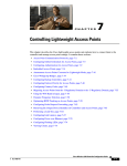
A Management Service manages and monitors only the iSCSI Storage Appliances
and iSCSI Storage Hosts that are added to it in Adaptec Storage Manager. (In the
main window of Adaptec Storage Manager, the iSCSI Storage Appliances and iSCSI
Storage Hosts are listed under the Management Service, as shown in the figure on
page 17.)
Management Service
iSCSI Storage Host
iSCSI Storage Appliance
You must install the Management Service on at least one system on the same subnet
as your iSCSI Storage Appliance. See “Installing Adaptec Storage Manager” on
page 27 for more information.
Adaptec recommends that you install the Management Service on the same system
as the GUI and Agent; however, it can be installed anywhere on your IP SAN, as
long as it’s on the same subnet as your iSCSI Storage Appliance.
Note You can install and add multiple Management Services to Adaptec Storage
Manager, if you want some of your iSCSI Storage Appliances to be configured and
managed separately from others. An individual iSCSI Storage Appliance can be
added to one Management Service only.
Windows Support
Windows Support is a bundle of software components that’s offered as an installation
option for systems running Windows 2003 only. (Component support varies by
operating system. See page 211 for more information.) Windows support includes:
• Multipath Input Output (MPIO) Device Specific Module (DSM) Driver—Supports
multiple redundant physical paths between your iSCSI Storage Appliance and
your iSCSI Storage Hosts, and supports mirror failover. Supported on systems
running Windows 2003 R2 only.
• Provisioning Agent—Automates functions such as volume and snapshot creation.
Supported on systems running Windows 2003 only.
• Virtual Disk Services (VDS) Provider—Enables third-party management tools to
configure your iSCSI Storage Appliance. Supported on systems running
Windows 2003.
• Volume ShadowCopy Service (VSS) Provider—Enables the creation of applicationand file-consistent snapshots. Supported on systems running Windows 2003
only.
Windows Support must be installed on any system that will be an iSCSI Storage
Host. Windows Support can be installed on any system that requires support for
third-party management tools. See “Installing Adaptec Storage Manager” on page
27 for more information.
Planning Your IP SAN Configuration and Setup
As you plan your IP SAN, use this table to understand which Adaptec Storage
Manager components can or must be installed on your IP SAN systems.
Required
Install...
On...
To...
GUI and Agent
At least one system on
your IP SAN
Build, manage, and
monitor your IP SAN
Management Service At least one system on
Build, manage, and
the same subnet as your
monitor your IP SAN
iSCSI Storage Appliance
(Adaptec recommends it
be the same system as the
GUI and Agent)
Optional
Windows Support
(see page 17)
All Windows 2003
systems on your IP SAN
that will be iSCSI Storage
Hosts.
Provision storage
automatically, create
volume snapshots, create
synchronous mirrors, use
Adaptec Storage Manager
with non-Adaptec storage
management tools
Note See page 211 for a complete list of supported Adaptec Storage Manager
features by OS. For additional help planning your IP SAN, see “Sample IP SAN
Configurations” on page 18.
Maximum Supported Connections
When building or expanding your IP SAN, ensure that you don’t exceed these
connection limitations for your iSCSI Storage Appliance. To each separate iSCSI
Storage Appliance, you can connect:
• Up to 100 Serial Attached SCSI (SAS) disk drives
• Up to 52 SATA II disk drives
Note Re-initialize any previously used disk drive that was originally initialized by
another RAID controller before connecting it to your iSCSI Storage Appliance. Refer
to your operating system documentation for instructions.
Sample IP SAN Configurations
This section provides configuration examples that illustrate the storage
management options and Adaptec Storage Manager installation requirements for
each option.
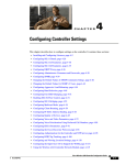
Basic Configuration #1
Note that because there is only one iSCSI Storage Appliance on this network,
mirroring is not supported.
iSCSI Storage Appliance
iSCSI
Windows Small Business Server 2003:
• Email server with automatically provisioned
storage
• Adaptec Storage Manager components installed:
GUI and Agent, Management Service, Windows
Support
Net A
Net A
LAN
Net A
Net A
Red Hat Enterprise Linux 5
• Workstations with manually provisioned storage.
• Adaptec Storage Manager components installed: None
Basic Configuration #2
Note that because there is only one iSCSI Storage Appliance on this network,
mirroring is not supported.
SUSE Linux Enterprise Server 9
• Backup server with manually provisioned storage
• Adaptec Storage Manager components installed:
GUI and Agent, Management Service
iSCSI
Net A
Windows Small Business
Server 2003
• Email server with
automatically
provisioned storage
• Adaptec Storage
Manager components
installed: Windows
Support
Net A
Net A
GbE Switch
Net A
iSCSI Storage Appliance
Net A
Net B
Red Hat Enterprise Linux 5 Workstations
• Manually provisioned storage
• Adaptec Storage Manager components
installed: None
Net B
LAN
Net B
Windows XP Workstations
• No provisioned storage
• Adaptec Storage Manager components
installed: None
Configuration with Mirroring
Note that because there are two iSCSI Storage Appliances on this network,
mirroring is supported.
Red Hat Enterprise Linux 5
• Backup Server with manually provisioned storage
• Adaptec Storage Manager components installed: None
iSCSI
Net A
iSCSI
iSCSI Storage Appliances
(volumes being mirrored)
Windows Server 2003
• Email server with
automatically provisioned
storage
• Adaptec Storage Manager
components installed: GUI
and Agent, Management
Service, Windows Support
Net A
Net A
Net A
GbE Switch
Net A
Net A
Net B
SUSE Linux Enterprise Server 9
Workstations
• Manually provisioned storage
• Adaptec Storage Manager components
Net B
LAN
Net B
Windows XP Workstations
• No provisioned storage
• Adaptec Storage Manager components installed: None
Configuration with Two Subnets
Note that because there is only one iSCSI Storage Appliance on this network,
mirroring is not supported.
GbE Switch
Net A
iSCSI
iSCSI Storage Appliance
iSCSI
Net B
Net A
Windows Small Business
Server 2003
• File server with
automatically provisioned
storage
• Adaptec Storage Manager
components installed: GUI
and Agent, Management
Service, Windows Support
GbE Switch
Net B
Net C
Net C
Windows Server 2003
• Email server with
automatically
provisioned storage
• Adaptec Storage
Manager components
installed: Windows
Support
GbE Switch
Net C
Net C
Net C
Windows XP, SUSE Linux Enterprise Server 9 Workstations
• No provisioned storage
• Adaptec Storage Manager components installed: None
Configuration with Multipath Access
Note that because there is only one iSCSI Storage Appliance on this network,
mirroring is not supported.
iSCSI Storage Appliance
iSCSI
Net A
Net B
GbE Switch
GbE Switch
Net A
Net B
Windows Data Center 2003
• File server with automatically provisioned
storage
• Adaptec Storage Manager components
installed: GUI and Agent, Management
Service, Windows Support
Net C
GbE Switch
Net C
Net C
Net C
Red Hat Enterprise Linux 5, SUSE Linux Enterprise Server 9 Workstations
• No provisioned storage
• Adaptec Storage Manager components installed: None
Building an IP SAN Without a DHCP Server
If you will be adding your iSCSI Storage Appliance to a network without a DHCP
server, the IP address will default to 10.10.10.10. Follow the instructions in this
section to place the server on your IP subnet before using Adaptec Storage Manager
to configure the server as an iSCSI Storage Appliance.
1 On a system in your environment (for instance, the system where you will install
Adaptec Storage Manager and the Management Service), set the IP address to the
same subnet as the iSCSI Storage Appliance (10.10.10.x).
2 To open a command prompt and ping the iSCSI Storage Appliance to ensure you
have communication, enter this command:
ping 10.10.10.10
3 Once you have confirmed that you can communicate with the iSCSI Storage
Appliance, telnet to the server by entering this command:
telnet 10.10.10.10
4 You will automatically be placed in the CLI Installation wizard. To exit the
wizard and go to the administrator prompt, enter this command:
*abort
5 If prompted for an ID and password, enter:
admin/admin (the defaults)
6 To change the IP address, type these commands, pressing Enter after each line:
interface
manage eth0
ip xxx.xxx.xxx.xxx (the IP address you want to give your iSCSI Storage Appliance)
It will take a few seconds for the IP address to change, and you will lose
connection to the iSCSI Storage Appliance. The LCD screen on the Snap Server
700i Series bezel will show the new IP address.
7 Continue with “Installing Adaptec Storage Manager” on page 27 to begin your IP
SAN setup.
Note If the system you used to change the iSCSI Storage Appliance’s IP address is
the one on which you’ll install Adaptec Storage Manager and the Management
Service, be sure to change your Management host back to the subnet you intend to
use for managing your iSCSI Storage Appliance(s).
System Requirements
• PC-compatible computer with a single Intel Pentium 1.2 GHz processor or better,
or equivalent, with a supported OS and an iSCSI initiator (see the following
table).
Note All OSs must have the latest Service Packs or Updates installed.
Supported OSs
Windows Server 2003 32-bit or 64-bit:
iSCSI Initiators Supported by
OSs
• Enterprise Edition or Enterprise Edition R2
Microsoft iSCSI Software Initiator v.2.04
or higher
• Standard Edition or Standard Edition R2
Q-Logic® QLA4050C Host Bus Adapter
• Web Edition
Q-Logic QLA4052C Host Bus Adapter
Windows Small Business Server 2003 or Small
Business Server 2003 R2
Windows Data Center 2003 or Data Center 2003 R2
Windows XP (all versions), 32- or 64-bit
Microsoft iSCSI Software Initiator v.2.04
or higher
Red Hat Enterprise Linux 4 U4, 32- or 64-bit
Q-Logic® QLA4050C Host Bus Adapter
SUSE Linux Enterprise Server 9, 32- or 64-bit
Q-Logic QLA4052C Host Bus Adapter
Bundled Cisco® iSCSI Initiator
Red Hat Enterprise Linux 5 U4, 32- or 64-bit
Bundled Open-iSCSI Initiator
VMware ESX Server 3.X.X
Bundled Software Initiator
Note An iSCSI initiator is only required on a system that will be accessing iSCSI
storage. The Microsoft iSCSI Software Initiator must be installed on Windows
2003 systems in addition to a hardware initiator.
• At least 512 MB of RAM
• 135 MB of free drive space
• CD drive
• 256 color video mode (optional—required only if the GUI will be installed)
Chapter 3
Installing Adaptec Storage
Manager
This chapter explains how to install Adaptec Storage Manager.
Before You Begin
1 Ensure you understand the installation options described in “Introduction to
Adaptec Storage Manager for iSCSI Storage” on page 13.
Adaptec Storage Manager does not need to be installed on a system unless it’s
being used as an iSCSI Storage Host or as the location of the GUI and Agent and/
or Management Service.
2 Ensure that you have installed an iSCSI initiator in each system to which you’ll be
provisioning storage. Supported iSCSI initiators are listed in “iSCSI Initiator
Support by OS” on page 210.
3 Ensure that each system meets the requirements listed on page 25.
Installing on Windows
This section describes how to install Adaptec Storage Manager on systems running
Windows. Adaptec Storage Manager includes the Java Runtime Environment (JRE).
See page 25 for a list of supported OSs. Not all Adaptec Storage Manager features
are supported by all Windows OSs. See “iSCSI Storage Feature Support” on page 14
for more information.
You will need the User CD to complete this task. Adaptec recommends doing the
first installation on the system where you’ll run the GUI and Management Service.
Note Advanced users only—You can perform a silent installation, if preferred. See
page 203.
To install Adaptec Storage Manager:
1 If a previous version of Adaptec Storage Manager is installed on your system,
uninstall it. (Refer to your operating system documentation for instructions.)
2 Power on the system, then insert the CD.
The Adaptec Storage Manager InstallShield wizard opens automatically. (If it
doesn’t, use Windows Explorer to display the CD contents, then double-click
setup.exe.)
3 Click Next to begin the installation.
4 Select I accept..., then click Next.
5 Select iSCSI Storage Setup, then click Next.
6 Select the features you want to install.
Ensure that you select these minimum required features:
• GUI and Agent—Required on at least one system
• Management Service—Required on at least one system on the same subnet as
your iSCSI Storage Appliance (Adaptec recommends the same system as the
GUI and Agent)
• Windows Support—Required on any system running Windows 2003, to create
an iSCSI Storage Host
Note The Windows Support option won’t appear during installation on any
OS besides Windows 2003.
7 Click Next.
8 If prompted, set a user name and password for the Management Service, then
click Next. (You won’t be prompted if you aren’t installing the Management
Service.)
9 If prompted, enter Management Service log-in information for VSS/VDS support:
10 Click Install.
11 When the installation is complete, click Finish.
Continue installing Adaptec Storage Manager, as needed. Then continue with
“Setting Up Your iSCSI Storage Appliance and IP SAN” on page 33.
Installing on Linux
This section describes how to install Adaptec Storage Manager on systems running
Linux. Adaptec Storage Manager includes the Java Runtime Environment (JRE).
See page 25 for a list of supported Linux OSs. Not all Adaptec Storage Manager
features are supported by Linux. See “iSCSI Storage Feature Support” on page 14
for more information.
Before You Begin
You will need the User CD to complete this task.
If you are installing on systems running Red Hat Enterprise Linux, you will need to
install packages from the Red Hat Linux installation CD.
Note The version strings in the file names may be different from what’s shown in
the examples below. Check the version strings on your Red Hat installation CD.
• Install these two packages:
compat-libstdc++-7.3-2.96.122.i386.rpm
compat-libstdc++--devel-7.3-2.96.122.i386.rpm
For example, type:
rpm --install /mnt/compat-libstdc++-7.3-2.96.122.i386.rpm
where mnt is the mount point of the CD-ROM drive.
• (Red Hat Enterprise Linux 4 only), install this package:
xorg-x11-deprecated-libs-6.8.1-23.i386.rpm
• (Red Hat Enterprise Linux 5 only), install one of these packages:
libXp-1.0.0-8.i386.rpm (for a 32-bit OS)
or
libXp-1.0.0-8.x86.rpm (for a 64-bit OS)
If a previous version of Adaptec Storage Manager is installed on your system, you
must remove it before beginning this installation. Any customization files you
created with the previous version are saved and used in the upgrade.
To remove Adaptec Storage Manager GUI, enter this command:
rpm --erase StorMan.
To uninstall the Management Service, enter these commands:
• Stop the management service —sh /etc/init.d/asm-mgmt stop
• Erase the rpm—rpm --erase asm-mgmt
Installing Adaptec Storage Manager
Note To run Adaptec Storage Manager on Red Hat Enterprise Linux 64-bit, you
must complete a standard installation with Compatibility Arch Support.
To install Adaptec Storage Manager:
1 Insert then mount the CD:
For Red Hat mount /dev/cdrom /mnt/cdrom
For SUSE
mount /dev/cdrom /media/cdrom
2 Change to the cdrom directory:
For Red Hat cd /mnt/cdrom/linux/manager
For SUSE
cd /media/cdrom/linux/manager
3 Extract the RPM package and install it:
rpm --install ./StorMan*.rpm
4 To install the Management Service:
# rpm -i asm-mgmt-5.10-<OS-specific RPM>.rpm
where OS-specific RPM is the rpm for the OS. For example: asm-mgmt-5.101012.rhel5.i586
5 Continue with “Creating an Administrator and Starting the Management
Service”.
Creating an Administrator and Starting the Management Service
By default, Adaptec Storage Manager includes only one user account, the
Administrator (which allows full access to your IP SAN and all Adaptec Storage
Manager features). You use the Administrator user name and password to log into
the Management Service.
To set up the Administrator account and start the Management Service, as root:
1 Enter this command:
/opt/asm-mgmt/sbin/setup
2 When prompted, press Enter to select admin as the Administrator user name.
3 When prompted, enter a password for the Administrator. When prompted, re-
enter the password.
Linux shuts down and restarts the Management Service.
4 Unmount the CD:
For Red Hat umount /mnt/cdrom
For SUSE
umount /media/cdrom
If you require the GUI and Agent or Management Service on more than one Linux
system, repeat the steps in this section. Otherwise, continue with “Setting Up Your
iSCSI Storage Appliance and IP SAN” on page 33.
Using Adaptec Storage Manager with a Firewall
If your network includes a firewall, you must unblock these ports:
• 8003 (TCP)—Allows inbound connections to the system running the Management
Service; allows outgoing connections on systems running the Windows Support
components( (see page 17).
• 34580 (TCP)—Allows outbound connections from the system running the
Management Service; allows inbound connections for systems running the
Provisioning Agent (see page 17).
• 34581 (TCP)—Allows outbound connections from the system running the
Management Service; allows inbound connections for systems running the
Provisioning Agent (see page 17).
• 34570 to 34579 (TCP)—Supports Direct Attached Storage.
• 34570 (UDP)—Supports Direct Attached Storage.
• 34577 to 34580 (UDP)—Supports Direct Attached Storage.
If you have installed the GUI and Agent or Management Service on a system
running Windows XP, you must also unblock the javaw process in the Windows
firewall. Refer to your operating system documentation for instructions.
Chapter 4
Setting Up Your iSCSI Storage
Appliance and IP SAN
Once you have installed Adaptec Storage Manager, your next task is to configure
your iSCSI Storage Appliance and set up your iSCSI storage. Adaptec Storage
Manager provides a wizard to guide you through these steps.
An Overview of the Setup Process
Adaptec Storage Manager provides automatic prompts and a wizard to help you
configure your iSCSI Storage Appliance and set up your iSCSI storage. This is an
overview of the seven basic steps:
1 Start Adaptec Storage Manager. Adaptec Storage Manager then prompts you to
log in to a Management Service and add your iSCSI Storage Appliance.
2 The wizard opens automatically and prompts you configure your iSCSI Storage
Appliance.
3 Register your iSCSI Storage Appliance.
4 The wizard prompts you create RAID pools (pools). Pools can be used
immediately to provision storage; you don’t have to wait for them to finish
building and verifying.
5 The wizard prompts you provision storage to your systems automatically
(systems running Windows 2003 only) or manually.
6 Re-open the wizard to add more iSCSI Storage Appliances, create more pools,
and provision more storage, as required.
Once setup in Adaptec Storage Manager is complete, two steps remain:
7 Log in to manually provisioned iSCSI storage.
Note Setup time depends on the amount of storage and number and types of
systems in your IP SAN.
Before You Begin
• Ensure that a supported iSCSI initiator is installed on each system to which you’ll
be provisioning storage. (All windows 2003 systems must have the Microsoft
Software Initiator installed, even if a hardware iSCSI initiator is also installed.)
See “iSCSI Initiator Support by OS” on page 210 for a complete listing.
• Ensure that Adaptec Storage Manager’s Windows Support components are
installed on all systems running Windows 2003 (iSCSI Storage Hosts).
• Prepare these values for the iSCSI Storage Appliance:
• A name for the iSCSI Storage Appliance (the host name); the name can be any
combination of alphabetical and/or numerical characters
• The network domain to which the iSCSI Storage Appliance belongs; the name
can be any combination of alphabetical and/or numerical characters
• A password for administrator-level (full) access to the CLI, if required
• A password for operator-level (limited) access to the CLI, if required
Note The administrator- and operator-level passwords both default to admin if
you don’t customize them.
• IP addresses for each Ethernet Port on the iSCSI Storage Appliance
• The netmask of the iSCSI Storage Appliance
• The IP address to be used for broadcasts
• Optional:
•Default gateway address—The name or IP address of a router where packets
are sent if their destinations are not defined
•DNS server IP addresses—IP addresses of up to 3 systems that will act as
DNS servers
• If you are not on a DHCP network, ensure that IP addresses have been given to
all iSCSI Storage Appliances. See “Building an IP SAN Without a DHCP Server”
on page 24 for more information.
Step 1: Starting Adaptec Storage Manager
Note You need root or administrative privileges to run Adaptec Storage Manager.
You can’t run multiple instances of Adaptec Storage Manager on the same system.
1 Start Adaptec Storage Manager.
• On a system running Windows, click Start > Programs > Adaptec Storage
Manager.
• On a system running Linux:
a Type cd /usr/StorMan, then press Enter to change to the Adaptec Storage
Manager installation directory.
b Type sh StorMan.sh, then press Enter:
Adaptec Storage Manager opens
and the Login to Management
Service window pops up. If the
Management Service is installed
on the same system as the GUI,
the host name and user name
fields will be automatically filled
in.
2 Enter the Administrator
password you set when you
installed Adaptec Storage
Manager.
If the Management Service is not installed on the local system, enter the name or
TCP/IP address of the system on which the Management Service is installed,
then enter the Administrator user name and password you set when you
installed Adaptec Storage Manager.
Note If you want to be prompted to log in to the Management Service each time
Adaptec Storage Manager is opened, uncheck the Save user name/password
check box. You might want to do this if some users have user-level access only to
Adaptec Storage Manager. See page 48 for more information.
The wizard opens and the Add iSCSI
Storage Appliance window pops up.
Note If your iSCSI Storage Appliance
is on a network without a DHCP
server, complete the steps in
“Building an IP SAN Without a DHCP Server” on page 24 before you continue
with this section.
3 Enter the host name or TCP/IP address of your iSCSI Storage Appliance, then
click Add. The TCP/IP address appears on the front panel LCD display of your
Snap Server 700i Series.
Note An iSCSI Storage Appliance can be associated with (or added to) only one
Management Service at a time.
If prompted, click OK, enter the Administrator password for the iSCSI Storage
Appliance, then click Add. (You will only be prompted for a password if this
iSCSI Storage Appliance was added to another Management Service previously.)
The default password is admin.
The iSCSI Storage Appliance is added to Adaptec Storage Manager.
Step 2: Configuring the iSCSI Storage Appliance
The wizard comprises three configuration steps, listed in the left panel:
• Configure iSCSI Storage Appliance
• Create RAID pools
• Provision Storage
This section explains the steps in the order in which they’re presented in the wizard.
To configure your iSCSI Storage Appliance:
1 Select the iSCSI Storage Appliance (shown as ‘OnTarget’ in the previous figure),
then click Next.
2 Under Network settings, enter the values you prepared in “Before You Begin” on
page 34.
Enter a name for the iSCSI Storage Appliance and the network domain to which
the iSCSI Storage Appliance belongs.
Enter a gateway name or IP address, or accept the default gateway.
Enter IP addresses for up to three domain name servers, if required.
3 (Optional) Under CLI settings, change the Administrator and Operator passwords
from their defaults. (By default, both passwords are ‘admin’.)
4 Click Next, then set values for each Ethernet port on your iSCSI Storage
Appliance, using the tabs at the top of the window to ensure that all ports are
configured. Use static IP addresses for each port, and ensure that DHCP is
deselected.
Click tabs to
view other
ports
Deselect
DHCP
Note By default, Ethernet Port 0 is the management port and is used by the
Management Service to communicate with your iSCSI Storage Appliances; it is
also an iSCSI port. You can configure Ethernet Port 0 as a management port only
by selecting that option in the Port Type drop-down menu.
5 Click Next. By default, the current date and time is used for the iSCSI Storage
Appliance. You can choose to manually set the date and time values, if required.
Note The Adaptec OnTarget operating system does not automatically adjust the
time setting on your iSCSI Storage Appliance to accommodate Daylight Saving
Time. However, the appliance uses the time setting for event timestamps only;
the appliance time setting is not used for job schedules or other functions.
6 Click Next, confirm the settings for this iSCSI Storage Appliance, then click Apply.
The settings are applied to the iSCSI Storage Appliance.
7 Click Register Now, then follow the online instructions to register your iSCSI
Storage Appliance.
The wizard continues to the Create RAID Pools step.
Step 3: Creating RAID Pools
The wizard offers two methods for creating (or configuring) pools—express
configuration and custom configuration. This section describes how to use the
custom configuration method.
The custom configuration option steps you through the manual process of creating
pools, helping you group disk drives, set RAID levels, determine pool size, and
configure advanced settings. Use this option when you want to create customized
pools with any or all available disk drives. Up to 20 pools are supported on a single
iSCSI Storage Appliance.
Note For instructions on creating pools using express configuration, see page 95.
To build pools with the custom method:
1 Select Custom configuration..., then click Next.
2 Select a RAID level.
The most common RAID levels are listed first; advanced RAID levels are
available by clicking Advanced settings.
Note Although all RAID levels are listed in the wizard, the RAID levels available
for your pools depend on the number of disk drives in your iSCSI Storage
Appliance. See “RAID Quick Reference” on page 201 for more information.
3 Click Next.
4 In the Physical Devices panel, enter a name for the pool. Use a meaningful name
that will help you easily identify it later. Pool names can be up to 15 characters
long.
If you don’t have enough disk drives to create a pool with the RAID level you
chose in the previous step, click Back to select a new RAID level.
5 Select the disk drives you want to use in the pool. (Adaptec Storage Manager
prompts you to select the correct number of disk drives.)
Note Adaptec recommends that you not combine SAS and SATA disk drives
within the same pool. Adaptec Storage Manager generates a warning if you try to
create a pool using a combination of SAS and SATA disk drives.
Hot Spare
Button
By default, Adaptec Storage Manager automatically sets the size of the pool and
maximizes the capacity of the disk drives you select.
6 (Optional) Create a global hot spare by control-clicking on an available disk drive;
alternatively, click the Create Global Hot Spare button, then select an available
disk drive.
A plus sign (+) appears to indicate that the selected drive will be designated as a
hot spare, as shown in the previous figure. To remove a hot-spare designation
from a disk drive, control-click it again.
7 (Optional) Click Advanced Settings and customize the settings as required.
8 If you have no other available disk drives, skip to Step 10.
If you have available disk drives and want to create additional pools, click Add
pool to open a new tab in the wizard.
9 Repeat Steps 2 to 8 for each pool that you want to create.
10 Click Next, review the pool settings, click Apply, then click Yes to create the pools.
Adaptec Storage Manager creates the pool(s). You can use the pool immediately to
provision storage, without waiting for the build/verify process to complete. For
more information about pools, see “Creating and Modifying Pools” on page 94.
Caution Don’t remove and reinsert any drive included in the pool while the pool
is building.
The wizard continues to the Provision Storage step.
Step 4: Provisioning Storage to Your Systems
The wizard provides two paths for storage provisioning, automatic provisioning
and manual provisioning. Which path you follow depends on which OS is running
on the system to which you’re provisioning:
• For systems running Windows 2003, see the next section.
• For systems running any other supported OS, see page 42.
You can provision storage from a new pool immediately. You don’t have to wait for
the pool’s build/verify process to complete.
Provisioning Storage Automatically
Note This task is supported by systems running Windows 2003 (iSCSI Storage
Hosts) only.
When you provision storage to an iSCSI Storage Host, you create a volume in
Adaptec Storage Manager that automatically appears as a formatted disk drive on
the iSCSI Storage Host and can be used right away to store data. You don’t have to
manually partition or format the volume on the iSCSI Storage Host.
1 In the Add iSCSI Storage Host window of the wizard, enter the host name of a
Windows 2003 system. Alternatively, if you assigned a static IP address to the
system, enter it instead of the host name. Then, click Add.
The system appears in the Select iSCSI Storage Host list.
2 Select the iSCSI Storage Host you just added, then click Next.
3 Enter a size for the volume. (Adaptec Storage Manager won’t allow you to enter a
number greater than the amount of available pool space.)
4 Enter a name (or label) for the volume. Use a meaningful name that will help you
easily identify it later.
5 Select a drive letter for the volume. Only unused drive letters are available in the
Drive Letter of Empty Directory drop-down list.
6 (Optional) Click the Advanced settings arrow and adjust the settings as required.
Note Adaptec highly recommends using CHAP authentication. Avoid disabling
authentication. (See “Controlling Access to Your IP SAN with Authentication” on
page 85 for more information.)
7 In the Pools list, select the pool to create the volume.
The Available Space column of the Pools list shows which pools have sufficient
space for the new volume. When you select a pool, the amount of available space
is automatically adjusted.
If you have no more available pool space, skip to Step 9.
8 If you have pool space available and want to create additional volumes for this
iSCSI Storage Host, click Add volume to open a new tab in the wizard.
Repeat this step to add volumes for this iSCSI Storage Host, as required.
9 Click Next, review the volume settings, then click Apply.
Adaptec Storage Manager begins to create the volume(s). The wizard closes. To
use the Job Manager to monitor the volume creation, see “Monitoring Jobs in
Progress” on page 115.
You can begin using the volume for storage immediately, without waiting for the
build/verify process to complete. For more information about volumes, see
“Creating and Modifying Volumes” on page 102.
To provision more storage, see “Step 5: Continuing to Build Your IP SAN” on
page 46.
Provisioning Storage Manually
Note Use this provisioning method for systems running any supported OS other
than Windows 2003.
When you provision storage manually, you create a logical device in Adaptec Storage
Manager that becomes the iSCSI target accessed by an iSCSI initiator. Once a logical
device is created, you must log into it from the iSCSI initiator and format it the same
way you would format a physical disk drive. Once the logical device is logged into
and formatted, it can be used to store data.
1 In the wizard, if the Add iSCSI Storage Host window has opened automatically,
click Cancel.
2 Select Manual provisioning, then click Next.
3 Select the pool you want by clicking its tab in the upper left-hand side of the
window, then click Add.
A logical device with default settings appears in the Logical Devices panel. By
default, the logical device is the same size as the pool.
The Pool 1 tab opens by default
Logical
device
added
4 Change the logical device’s default settings by continuing with Step 5, or accept
the default settings and continue with Step 8.
5 Click inside the Size field and enter the size of the logical device. Specify MB, GB,
or TB as the size unit (for instance, 20 GB).
6 Click inside the Name field and enter a name for the logical device. Logical device
names can be up to 16 characters long.
7 Click inside the Authentication box and select an authentication method. (See
“Controlling Access to Your IP SAN with Authentication” on page 85 for more
information.) CHAP authentication is set by default.
• To use CHAP authentication, click Set CHAP secret, enter a user name and
password, then click Add. Click Cancel to close the window.
Note If you are using CHAP with the Microsoft iSCSI initiator, the CHAP
password must be 12–16 characters long or it will be rejected by the iSCSI
initiator.
You can set different user names and passwords for each logical device you
create, or you can create one user name and password and apply it to all the
logical devices you create during this configuration session (existing logical
devices remain unchanged). To apply the same CHAP secret user name and
password to all logical devices in this session, set the same user name and
password for the first logical device, then select Apply the user name and
password... when you repeat this step for your second logical device.
• If you select SRP authentication, click inside the Scope field to type a unique
name for the scope, or choose an existing name from the drop-down menu.
Note If you are using Internet Storage Name Service (iSNS) to discover iSCSI
targets and want to control which logical devices can be logged into by which
iSCSI initiators, you must use CHAP authentication. Without CHAP
authentication, all iSCSI initiators will be able to log in to all logical devices.
8 If you have available space in this pool and want to create additional logical
devices, repeat Step 3 to Step 7.
Each pool can support up to 512 logical devices. The Physical Devices panel of
the window monitors the used and free space available in the pool you’re
working in.
Available
space is
tracked
To create a new logical device using the same settings as an existing one, select
that logical device, then click Replicate.
9 Repeat Step 3 to Step 8 for each pool on your iSCSI Storage Appliance, as
required.
10 Click Next.
11 Create a discovery Control List. (A discovery control list allows one or more
specified iSCSI initiators to discover an iSCSI target while preventing other iSCSI
initiators from discovering it. See page 83 for more information.)
a Click Add Initiator.
The Add iSCSI Initiator window opens.
b Enter the IQN (iSCSI Qualified Name) assigned to the iSCSI initiator.
c Enter a name (or alias) for the initiator. The name must begin with a alphabetic
character, and can contain only letters and numbers.
d (Optional—VMware ESX users only) Click Advanced options, then enable Uses
permanent discovery session.
e (Optional—Advanced users only) Click Advanced settings to enable or disable
Protocol Data Unit, iSCSI ping, and discovery settings.
Note Refer to your iSCSI initiator’s documentation for more information about
the advanced settings.
f Click OK.
Note The iSCSI initiator appears in the Initiators drop-down menu.
g Repeat Steps a to f to add more initiators, if required.
h From the Initiators drop-down menu, select the initiator you want.
i From the list of logical devices, select the logical device(s) that you want the
selected initiator to discover, then click the right arrow (>).
j Repeat Steps h and i for each iSCSI initiator.
Note Each logical device can support up to 32 iSCSI initiators. For more
information about auto-discovery control lists, see page 83.
k Click Next, review the configuration summary, click Apply, then click Yes.
Adaptec Storage Manager begins to build the logical device(s). The wizard closes.
For more information about logical devices, see “Creating and Modifying Logical
Devices” on page 104.
Before you can begin to use the iSCSI storage, you must log in to the logical
devices (iSCSI targets), then partition and format them. See “Step 6: Logging in to
the iSCSI Storage” on page 46 for instructions.
Step 5: Continuing to Build Your IP SAN
To add or configure another appliance, create more pools, or provision more
storage, re-open the wizard by right-clicking the Management Service in the
Enterprise View, then selecting Configure SAN.
For more information on each task, follow the instructions in this chapter or see
“Modifying Your iSCSI Storage” on page 91.
Step 6: Logging in to the iSCSI Storage
If all the systems on your IP SAN are iSCSI Storage Hosts, skip to “Step 7:
Registering Your iSCSI Storage Appliance” on page 47.
If you have systems on your IP SAN running Windows XP, Linux, or VMware, the
next step is to log in to the logical devices from those systems, then partition and
format the logical devices. Log-in varies by iSCSI initiator and OS; for complete
instructions, refer to the documentation provided with your iSCSI initiator and
system.
The basic steps are:
1 Run the iSCSI initiator’s management tool.
2 Point the initiator to the IP address of an iSCSI port on your iSCSI Storage
Appliance (set in Step 4 on page 37).
3 Discover the iSCSI target that you want to access from the local system. (The
iSCSI targets are the logical devices you created in “Provisioning Storage
Manually” on page 42.
4 Log in to the iSCSI target.
5 Partition and format the logical device on the local system, just as you would any
new locally installed disk drive.
6 Repeat these steps for each system on your IP SAN that is not running Windows
2003. When you are finished, continue with “Step 7: Registering Your iSCSI
Storage Appliance” on page 47.
Step 7: Registering Your iSCSI Storage Appliance
If you didn’t register your iSCSI Storage Appliance at the end of “Step 2:
Configuring the iSCSI Storage Appliance” on page 36, you will be prompted to
register again when:
• You next log in to the Management Service. Adaptec Storage Manager finds any
unregistered iSCSI Storage Appliances associated with that Management Service
and prompts you to register each one individually.
• You next view or change the configuration settings on that iSCSI Storage
Appliance in the wizard.
You must register your iSCSI Storage Appliance to receive notification of new
software releases and updates, and to receive technical support.
Beginning to Use Your IP SAN
Once setup is complete, use Adaptec Storage Manager to manage and monitor your
IP SAN.
Logging In To Adaptec Storage Manager Next Time
Once your IP SAN is set up, each time you start Adaptec Storage Manager, any
Management Services on the iSCSI Storage branch will be grayed out.
To begin a new session on Adaptec Storage Manager, click on the grayed out
Management Service.
Unless you enable the ‘Save User’ feature when you log in to the Management
Service (see page 35), you will be prompted to enter a user name and password.
Once you have logged in and the connection to the Management Service is reestablished, all iSCSI Storage Appliances and iSCSI Storage Hosts associated with
that Management Service appear in the Enterprise View and you can begin to
monitor and manage your IP SAN.
Allowing Other Users To Log In To Your IP SAN
By default, Adaptec Storage Manager includes only one user account, the
Administrator (which allows full access to your IP SAN and all Adaptec Storage
Manager features).
After setup is complete, if you want to maintain security but allow other users
limited or full access to your IP SAN, you can add them to Adaptec Storage
Manager, assign them an access privilege level, and set passwords for them to use
when logging in to the Management Service.
Note You can log into the same Management Service from more than one GUI at the
same time, even if you log in at different access privilege levels.
For more information, see “Limiting User Access to Your IP SAN with the Security
Manager” on page 86.
Setting Up VSS/VDS Access
If you are using a VSS requester or a third-party VDS provisioning tool in a system
running Windows XP, Linux, or VMware, you must add that system to the
Microsoft VDS/VSS host list in Adaptec Storage Manager. (Refer to your Microsoft
VDS/VSS documentation for more information.)
The Management Service must be installed somewhere on the same network (or
subnet) as the VDS/VSS providers. The VDS/VSS providers can be installed on the
same system as the Management Service, or on a separate system.
Only systems on the VDS/VSS host list can complete jobs through the Management
Service, such as creating volumes or snapshots.
Note On iSCSI Storage Hosts, Adaptec Storage Manager automatically updates the
VDS/VSS host list during installation. No manual intervention is required.
Adding a System to the VDS/VSS Host List
To add a system to the VDS/VSS host list:
1 In the Enterprise View, right-click the Management Service, select Management
service actions, then click Manage VDS/VSS access.
The Microsoft VDS/VSS Access window opens.
2 Click Add.
The Enable Microsoft VDS/VSS Access from this
Host window opens.
3 Enter the host name of the system, then click Add.
Note To find the host name for a system, open a
command prompt window, type hostname, then
press Enter. Use the displayed host name in the
Enable Microsoft VDS/VSS Access from this Host window. You can’t use the
system’s IP address.
The host name appears in the host list.
4 Repeat Steps 2 and 3 to add more systems to the host list.
5 Click OK to close the Microsoft VDS/VSS Access window.
The systems you added to the host list can now complete jobs through the
Management Service.
Note If your system has problems connecting to the VDS Provider, see page 147 for
troubleshooting tips.
Removing a System from the VDS/VSS Host List
To remove a system from the VDS/VSS host list:
1 Open the Microsoft VDS/VSS Access window (see Step 1 on page 49).
2 Select the system you want to remove, then click Remove.
The system is removed from the host list.
3 Click OK to close the Microsoft VDS/VSS Access window.
Next Steps
Once setup is complete, use Adaptec Storage Manager to modify and monitor your
IP SAN.
Adding More Components
As your iSCSI storage requirements grow, you can add more components
(Management Services, iSCSI Storage Appliances, and iSCSI Storage Hosts) to your
IP SAN by following the instructions in “Adding More Components to Your IP
SAN” on page 91.
Protecting Your IP SAN
Adaptec recommends protecting your IP SAN using Adaptec Storage Manager’s
security features. For more information, see “Protecting Your Data” on page 61 and
“Controlling Access to Your IP SAN” on page 83.
Modifying, Maintaining, and Monitoring Your IP SAN
Complete instructions on modifying your iSCSI storage, maintaining your iSCSI
Storage Appliance and Adaptec Storage Manager, and monitoring your iSCSI
storage, network attached storage, and IP SAN are provided in the remainder of this
Guide.
Chapter 5
Getting to Know Adaptec
Storage Manager
This chapter will help you familiarize yourself with the main features of Adaptec
Storage Manager and learn to navigate to the information you need.
Working in Adaptec Storage Manager
Adaptec Storage Manager provides multiple ways to work with its menus and
windows.
Most menu options are available by:
• Selecting items from the menu bar.
• Clicking buttons on the tool bar.
• Right-clicking on components in the main window. (Only tasks and windows
associated with a specific component are available on right-click menus.)
For simplicity, the tasks in this Guide are explained mainly using menu bar options.
About the Actions Menu
Most of the main tasks in
Adaptec Storage Manager are
part of the Actions menu on
the menu bar (as shown at right). Options on the Actions menu vary, depending on
which type of component is selected in the main window. For instance, iSCSI
Storage Hosts, disk drives, and hot spares each have specialized Actions menus.
Navigating the Main Window
The main window of Adaptec Storage Manager has three main panels—left, right,
and bottom—in addition to the other features shown in this figure.
The left panel always shows the Enterprise View; the bottom panel always shows
the Event Viewer. Different information, or views, appear in the right panel
depending on which component is selected in the Enterprise View. (In this example,
the iSCSI Storage Appliance is selected in the Enterprise View, and the right panel
displays the Physical Devices and Logical Devices Views.)
Enterprise View
Physical Devices View
Logical Devices View
Menu Bar
Tool Bar
Management
Service
iSCSI
Storage Host
iSCSI
Storage
Appliance
Event
Viewer
Resize the panels and scroll horizontally or vertically to view more or less
information.
The Enterprise View
The Enterprise View is an expandable tree with the iSCSI Storage branch (see
page 52).
The iSCSI Storage Branch
Under iSCSI Storage, the Enterprise View lists the Management Service (see
page 16), the iSCSI Storage Appliance, and any iSCSI Storage Hosts that are part of
your IP SAN.
Note The iSCSI Storage Appliance and the iSCSI Storage Hosts appear in the
Enterprise View under the Management Service that is monitoring them.
When you select a component in the Enterprise View, the disk drives, pools, or
other devices associated with it appear in the right-hand panel of the window, as
shown in these figures.
When you select an iSCSI Storage ...the storage volumes that have been provisioned to
Host in the Enterprise View...
that system appear in the Volumes View.
When you select the iSCSI
Storage Appliance in the
Enterprise View...
...the controller and disk drives it contains, and the pools and logical
devices created with those disk drives, appear in the Physical and
Logical Devices View.
You can perform most tasks by selecting a component in the Enterprise View and
working with its associated devices in the right-hand panel.
The Direct Attached Storage Branch
The Direct Attached Storage Branch lists any Adaptec DAS RAID controllers
installed on the local system and any Adaptec DAS RAID controllers that you are
managing remotely.
Note The Direct Attached Storage branch is not covered in this Guide—refer to the
Adaptec Storage Manager User’s Guide for Direct Attached Storage on the installation
CD that came with your Adaptec DAS RAID controller.
The Network Attached Storage Branch
Under Network Attached Storage, the Enterprise View lists any GuardianOSpowered Snap Servers on your network.
When you select Network Attached Storage in the Enterprise View, the
GuardianOS-powered Snap Servers on your network are listed in the right-hand
panel of the window.
When you select a GuardianOS-powered Snap Server in the Enterprise View, its
properties appear in the right-hand panel of the window, using an identical format
to the Properties panel used in Snap Server Manager (the management tool
provided with your GuardianOS-powered Snap Server).
For more information about monitoring GuardianOS-powered Snap Servers in
Adaptec Storage Manager, see page 132.
The Physical Devices View
When you select your iSCSI Storage Appliance in the Enterprise View, the
controller and disk drives it contains appear in the Physical Devices View.
Enclosure Management Device
This iSCSI Storage Appliance
contains......
...one controller and four
disk drives.
If an iSCSI Storage Appliance or enclosure contains an enclosure management
device, it also appears in the Physical Devices View. Right-click the enclosure
management device icon to view the status and properties of the enclosure’s
devices, such as its disk drives and fans.
Disk drives designated as hot spares have plus signs (+) beside them:
• A blue plus sign (shown at right) means that the spare is protecting at least
one pool.
• A hot spare with a yellow plus sign (shown at right) may not be large
enough to protect the pool it’s assigned to, or may not be assigned to a
pool.
With tool tips enabled (see page 141), hold your cursor over any disk drive to
see its status, port number, and maximum speed. You can also click the arrow,
shown at right, to see this same information for all the disk drives at the same
time. To reveal further information, use the View buttons to change how the disk
drives are displayed, as described in “Revealing More Information” on page 58.
A disk drive shaded in light blue is not part of any pool. A disk drive shaded
half light/half dark blue (as shown at right) has space available for additional
logical devices or snapshots.
To view the pools or logical devices associated with a particular disk drive, see “The
Logical Devices View” on page 56.
The Logical Devices View
When you select the iSCSI Storage Appliance in the Enterprise View, the pools and
logical devices associated with that appliance appear in the Logical Devices View.
(A pool is a collection of disk drives combined in a RAID set. A logical device is
created within a pool and is seen as a single iSCSI target.)
This appliance is connected
to...
...one controller and four disk
drives...
...from which one pool has been
created.
The RAID level of a logical device is indicated by the number inside the logical
device’s icon. For instance, the logical device shown at right has RAID 1.
Pools protected by hot spares have plus signs (+) beside them, as shown at
right.
With tool tips enabled (see page 141), hold your cursor over any pool to see its
name and size; hold your cursor over any logical device to see its name, size,
and status. You can also click the arrow, shown at right, to view this same
information for all pools or logical devices at the same time.
Select a pool to highlight the disk drives that comprise it in the Physical Devices
View, and the logical device created from it in the Logical Devices View.
The selected pool includes four disk drives and has been used to create
three logical devices.
You can also select any disk drive to see which (if any) pool it belongs to. A disk
drive shaded in light blue is not part of any pool.
The Volumes View
When you select an iSCSI Storage Host in the Enterprise View, the storage volumes
that have been provisioned to that system appear in the Volumes View.
This iSCSI Storage Host has... ...two storage volumes provisioned to it.
With tool tips enabled (see page 141), hold your cursor over any volume to see
its size and drive letter (as shown in the previous figure). You can also click
the arrow, shown at right, to see this same information for all volumes at the
same time. To reveal further information, use the View buttons to change how the
volumes are displayed, as described on page 58.
The Snapshots View
When you select a snapshot in the Enterprise View, the snapshots associated with
the volumes on your iSCSI Storage Hosts appear in the Snapshots View.
If you have created third-party snapshots (snapshots created using a tool other than
Adaptec Storage Manager), they also appear in the Snapshots View.
The volumes associated with
the iSCSI Storage Host...
...have four Adaptec Storage
Manager snapshots...
...and one third-party snapshot
associated with them.
Adaptec Storage Manager snapshots are organized by snapshot sets—one or
more snapshots created at the same time. With tool tips enabled (see page 141),
hold your cursor over any snapshot to see its name, volume ID, and mount
point (if any). You can also click the arrow, shown at right, to view this same
information for all snapshots at the same time.
Third-party snapshots display their basic properties only.
Revealing More Information
You can reveal more information about volumes, disk drives, pools, and logical
devices by using the View buttons (circled below) to change what information
displays.
Note Not all views are available for all components.
Default View
(Enclosure View)
Click the arrows to
expand list and
reveal basic
information.
Click this button to see the size capacities of your
disk drives. Disk drives or segments of disk drives
that are included in logical devices are shaded
brown.
Click this button to see the size capacities of your disk
drives relative to each other. (Also available in the
Volumes View.)
Checking System Status from the Main Window
Adaptec Storage Manager includes an Event Viewer for at-a-glance system and
event status information. The Event Viewer provides status information and
messages about activity (or events) occurring on your IP SAN. Double-click any
event to see more information in an easier-to-read format.
Warning- and Error-level icons, shown at right, appear next to
components (such as systems and pools) affected by a failure or
error, creating a trail, or rapid fault isolation, that helps you identify
the source of a problem when it occurs. See “Identifying Failed or
Failing Components” on page 148 for more information.
Enclosure
Warning
Disk Drive
Error
If your IP SAN includes a controller with a temperature sensor, or an enclosure with
an enclosure management device, such as a SCSI Accessed Fault-Tolerant Enclosure
(SAF-TE) processor, temperature, fan, and power module status is displayed by
status icons in the Physical Device view, as shown in the next figure. These status
icons change color to indicate status (see “What Do the Status Icons Mean?” on
page 119).
Status Icons
Power Module Status
Temperature Status
Battery Status
Fan Status
For more information, see “Monitoring Status and Activity” on page 115.
Getting Help
Adaptec Storage Manager online Help includes conceptual information, glossary
definitions, and descriptions of on-screen menus and items, in addition to step-bystep instructions for completing tasks.
To open the online Help, click the Help button, or press the F1 key for contextsensitive help.
Press the Help button in a dialog box or wizard for help with that specific dialog
box, window, or procedure.
For more information about the GuardianOS, and for instructions on using the
Administration Tool, refer to the Snap Server Administrator Guide on the User CD or
the Administration Tool online Help.
Uninstalling Adaptec Storage Manager
Uninstalling From Windows Systems
To uninstall Adaptec Storage Manager from a Windows system, use the Add or
Remove Programs tool in the Control Panel. All Adaptec Storage Manager
components, including the Management Service, will be uninstalled.
Uninstalling From Linux Systems
1 To uninstall Adaptec Storage Manager from a Linux system, type this command:
rpm --erase StorMan
2 To uninstall the Adaptec Storage Manager Management Service, enter these
commands:
• Stop the management service.sh /etc/init.d/asm-mgmt stop
• Erase the rpm.rpm --erase asm-mgmt
3 When prompted to stop the Management Service, type OK, then press Enter.
Adaptec Storage Manager and the Management Service are uninstalled.
Chapter 6
Protecting Your Data
In addition to the redundancy protection provided to your storage pools by RAID,
you can protect your data by assigning hot spares (disk drives that automatically
replace failed disk drives) to your storage pools, taking application-consistent
snapshots of it (“pictures” of your data at a particular point in time) for backup
purposes, and mirroring your data (creating an exact copy that is continuously
synchronized with the original).
This chapter explains how to use Adaptec Storage Manager to work with hot
spares, snapshots, and mirrored volumes.
Protecting Your Data with Hot Spares
A hot spare is a disk drive that automatically replaces any failed drive in a pool, and
can subsequently be used to rebuild that pool. (For more information, see
“Recovering from a Disk Drive Failure” on page 150.)
Hot spares assigned to iSCSI Storage pools are global hot spares—they protect any
pool in the iSCSI Storage Appliance (except RAID 0 logical devices). You can create
a hot spare either before or after you build your pools; you can also create a hot
spare while you’re creating a pool. To create a hot spare, see page 62.
An assigned hot spare are dedicated hot spares—they are used only to rebuild the
logical devices to which they are assigned.
Hot Spare Limitations
• You can’t create a hot spare for RAID 0 pools.
• You can’t create a hot spare from a disk drive that is already part of a pool.
• You should select a disk drive that is at least as big as the largest disk drive it
might replace.
• Adaptec recommends that you not designate a SAS hot spare for a pool
comprising SATA disk drives, or a SATA hot spare for a pool comprising SAS
disk drives.
Creating a Global Hot Spare for a Pool
This section describes how to designate a hot spare before or after you create a pool.
Note To designate a hot spare while you’re creating a pool, see Step 6 on page 39.
To designate a hot spare:
1 In the Enterprise View, select the iSCSI Storage Appliance.
In the Physical Devices View, click the disk drive you want to designate as a hot
spare. (See “Hot Spare Limitations” on page 61 for help selecting a disk drive.)
2 Click the Create Global Hot Spare button (shown at right).
A plus sign appears on the selected disk drive, indicating that it’s designated as a
hot spare. A plus sign also appears on the pool that includes the hot spare. (A
yellow plus sign indicates an error. See “What Do the Hot Spare Icons Mean?” on
page 63 for help solving the problem.)
Pool protected
by hot spare
Hot spare
Any other pools created on that iSCSI Storage Appliance are protected
automatically by that hot spare.
Assigning a Hot Spare to a Logical Device
Note You cannot assign a hot spare while a logical device is being built or modified.
To assign a hot spare drive to a logical device:
1 In the Physical Devices View, select an available (unused) disk drive.
2 In the Actions menu, click Create assigned hot-spare drive, then select the logical
device you want.
Note A plus sign appears on the selected disk drive, indicating that it’s designated
as a hot spare. (A yellow plus sign indicates an error. See “What Do the Hot Spare
Icons Mean?” on page 63 for help solving the problem.)
What Do the Hot Spare Icons Mean?
Icon
Explanation
Action
Healthy global or dedicated hot spare
No action required.
Hot spare is too small to protect the
pool(s) it’s assigned to
Designate larger disk drive as hot spare
Hot spare has been built into a pool
after disk drive failure
Designate replacement or other available
disk drive as new hot spare
Deleting a Hot Spare
You can delete a hot spare. You may want to do this to:
• Make disk drive space available for a pool or logical device.
• Remove the ‘hot spare’ designation from a disk drive that is no longer being used
as a hot spare.
To remove or delete a hot spare:
1 In the Enterprise View, select the iSCSI Storage Appliance associated with the hot
spare.
2 In the Physical Devices View, click the hot spare.
3 In the Actions menu bar, click Delete hot-spare drive.
The hot spare is deleted and the disk drive becomes available for other uses in
your IP SAN.
Backing Up Your Data with Snapshots
Note To create snapshots on systems running Windows XP, Linux, or VMware,
you must use the CLI (see page 179.) Snapshots created on these OSs are failconsistent only, as the VSS Provider is not supported by the OSs. We can now use
Target Based Snapshots in Windows XP and Linux operating systems.
Adaptec Storage Manager’s snapshot feature creates a frozen copy of a volume at a
point in time. A snapshot sets up a link between the source volume and the
underlying logical devices in your iSCSI Storage Appliance. When data on the
source volume changes, the differences are captured on the snapshot drive.
If an error occurs on the volume, you can roll back the volume to the point in time
when the snapshot was created. You can also use the snapshot feature for tape
backup, drive cloning, and multi-server rollout.
Adaptec Storage Manager has a snapshot wizard to help you create a snapshot and
snapshot sets (a group of snapshots taken at the same time). A snapshot can include
one volume or multiple volumes. You cannot create a snapshot of either a mirrored
volume (the mirror manager) nor its mirror (the mirror plex). You can’t work with
any individual snapshot in a snapshot set; only the complete snapshot set can be
mounted or deleted, for example.
You can choose to run a snapshot job immediately, or schedule it for another time.
Before You Begin
Ensure that the VSS Provider (see page 17) is installed on the system on which you
plan to take snapshots. Also ensure that Microsoft Hotfix 913648 or equivalent is
installed on the system. Refer to http://support.microsoft.com/kb/895092.
Creating a Snapshot from an iSCSI Storage Host Volume
You can create a up to 256 separate snapshots on one iSCSI Storage Appliance. (You
can include multiple volumes in one snapshot). When you are creating snapshots
for a mirrored volume, snapshots will be created on the mirror master plex only.
To create a snapshot:
1 In the Enterprise View, select the iSCSI Storage Host you want.
2 In the Volumes View, select any volume.
3 Click the Snapshots button (shown at right). Or, In the Actions menu, select
Create snapshot.
The wizard opens.
4 Select the volume(s) you want to include in the snapshot set.
Note If the volume you select has dependent volumes listed, Adaptec strongly
recommends that you copy the volume and its dependencies, to avoid losing
related data.
5 Type a name or description for the snapshot, then click Next.
The Snapshot Settings screen opens. The pool for the snapshot is automatically
assigned.
6 Set the mount point for the snapshot. (If you don’t want to mount the snapshot,
select None from the iSCSI Storage Host drop-down list, then skip to Step 7.)
a Select the iSCSI Storage Host where you want to mount the snapshot, then
assign a drive letter.
All volumes in a snapshot set are mounted or unmounted. If you mount the
snapshot set, all volumes are mounted on the same server.
b Set the access type (Read only or Read/Write).
c If you are copying multiple volumes, click the tab of the next volume, then
repeat Steps 4 to 6.
7 Click Apply to begin the snapshot immediately. The Job Manager opens (see
page 115) and the job begins.
To schedule the snapshot for a later time or to create the snapshot on a recurring
basis, see “Scheduling a Snapshot Job” on page 70.
When the snapshot has been created, it appears in the Enterprise View. Select any
snapshot in the Enterprise View to open the Snapshot View, shown in the next figure.
Caution Carefully monitor the capacity of the pool that contains your snapshots. At
this time, when the pool reaches maximum capacity, all snapshots contained within
it will go offline. See “Recovering Snapshots After a Pool Capacity Failure” on
page 154 for more information.
Mounting a Snapshot Set
When you create a snapshot set, you have the option to mount it to a specific system
on your IP SAN. (The individual snapshots within a snapshot set are either all
mounted or all unmounted. You can’t mount just some individual snapshots.) If
you choose not to mount a snapshot set during creation, you can mount it after it
has been created.
To mount a snapshot set:
1 In the Enterprise View, select the iSCSI Storage Host you want.
2 In the Snapshots View, select the title of the snapshot set.
Snapshot set title (text)
3 Click the Mount Snapshots button (shown at right). Or, In the Actions menu,
select Mount snapshot set.
The Mount Snapshot Set window opens.
4 Select the iSCSI Storage Host on which to mount the snapshots.
5 Set a mount point for the snapshots of each volume by selecting a drive letter or
entering the full path to an empty directory.
Each snapshot must have its own mount point.
6 Set the access type (Read only or Read/Write).
All snapshots in the snapshot set will have the same access type.
7 Click OK to mount the snapshot set.
Caution If you set up a recurring job that creates and mounts a snapshot on the
same disk drive, you must free the disk drive after each job or the job will fail.
Deleting a Snapshot Set
Although you can’t delete an individual snapshot, you can delete an entire
snapshot set.
To delete a snapshot set:
1 In the Snapshots View, select the title of the snapshot set.
2 Click the Delete Snapshots button (shown at right). Or, In the Actions menu,
select Delete snapshot set.
3 Click Yes to delete the snapshot set.
Creating Target Based Snapshots
ASM provides application consistent snapshots for Windows volumes (VSS). For
other operating systems you must use the command line utility to perform snapshot
operations. You can also snapshot logical devices using ASM, for non-Windows
operating systems. To perform a snapshot, launch ASM, right-click a logical device
and select the snapshot option. ASM will allow the user to create the snapshot
immediately or schedule the snapshot to occur at a later time.
To create a target based snapshot:
Note Ensure to disconnect all the initiators before creating a target based snapshot.
1 Create a logical device using manual provisioning from ASM.
2 Set the authentication type to either CHAP or None and assign to any initiator.
3 Login to the new logical device and store data in it.
4 Log off the initiator.
Note Always log off the parent before creating a target based snapshot, as target
based snapshots are not application consistent snapshots.
5 Select the target in the Enterprise View and right-click the logical device and
select Create Snapshot.
6 Provide a description to the target based snapshot.
7 Select the Access Type.
• Read Only
• Read Write
8 Select the Authentication Type.
• CHAP
• None
Note By default the authentication type is set to be same as the parent.
9 Assign to the initiator.
Note Assign to the provisioned system if you want to mount the TBS using mount
option.
10 When the target based snapshots are created the snapshots will be listed under
ASM snapshots in the Enterprise View.
Note If you create CLI snapshots, they will be listed under third party snapshots.
Mounting a Target Based Snapshot
You can mount a TBS onto any provisioned system. Complete these steps to mount
a target based snapshot onto a provisioned system.
Note Refresh the ASM once before trying to mount the TBS, to ensure that it selects
the latest available drive letter.
1 Select the Snapshot from the Enterprise View, right-click the snapshot and
choose an option to mount.
Note Only snapshots with correct file system can be mounted.
2 Select the drive letter and CHAP information.
3 Go to My Computer and check if the TBS is successfully mounted and has all the
data of the parent volume.
Performing Roll back of a Mirror Snapshot
You cannot perform a snapshot rollback of a mirrored volume. To rollback the user
will need to perform the following steps:
1 Break the mirrored volume into basic non-mirrored volumes.
2 Logout any initiator connections to the volume.
3 Issue rollback from the CLI and wait for rollback to complete.
4 Once rollback is complete, login to the volume.
5 Recreate the mirror with full resynchronization.
If a full resynchronization is required during a mirror failover, existing snapshots
on the slave plex that is being resynchronized will be deleted.
Performing Roll back of a Target Based Snapshot
Rollback operation copies the data from the snapshot volume to the original
volume. So if changes were made to the original volume, all such changes will be
lost and data at the time of snapshot taken will be replicated to the original volume.
1 After taking the snapshot, login to the original volume and modify the data,. Log
out both parent and snapshot volume from all initiators.
2 Select the Snapshot from the enterprise view and right-click on target based
snapshot and select Roll back Snapshot set.
3 3 To verify if the progress of the roll back, select the target in the Enterprise view
and check the roll back status.
4 Once the rollback is complete, login to the parent volume and verify if the
rollback is completed successfully.
Creating Volume Snapshots
Volume snapshots are snapshots of a file or directory on a specific volume, taken at
any time.
Note Volume snapshots are supported only in Windows 2003.
To create volume snapshots,
1 Create a pool.
2 Create a logical drive using the provisioning agent.
Note The pool should have capacity to hold all the snapshots you present in a
particular logical device.
3 Add file(s) to your logical device.
4 In ASM, click the provisioning agent in the Enterprise view. All the associated
volumes are display in the Physical and Logical Device view.
5 Right click the volume you want to snapshot and click Create Snapshot.
Note The maximum number of volumes you can include in a snapshot set is 4 from
a single iSCSI storage appliance, and is 9 if you are using 3 iSCSI storage appliances.
6 Select the volume you want to snapshot. Enter a description and click Next.
7 Select the Managed system, Drive and Access Type and click Next.
8 Click Apply to create the snapshot or Schedule to snapshot the volume at a
specific time.
Ensuring Pool Capacity for Your Snapshots
Ensuring that there is adequate capacity in a pool to maintain your snapshots is
extremely important. Currently, when a pool reaches maximum capacity, all
snapshots contained within it go offline and are only retrievable manually.
Always carefully monitor the capacity of any pool that contains snapshots to avoid
the lengthy retrieval process and prevent snapshot loss.
Recovering from a Pool Capacity Warning
Adaptec Storage Manager generates a warning message when pool capacity reaches
5%. A second warning message is generated when pool capacity reaches 3%.
When you receive one of these messages, delete any unneeded volumes from the
pool or expand the size of the pool as soon as possible.
Recovering from a Pool Capacity Failure
If pool capacity becomes exhausted, all snapshots within that pool (and all the
volumes on which the snapshots are based) go offline, and Adaptec Storage
Manager generates a failure message.
To recover, see “Recovering Snapshots After a Pool Capacity Failure” on page 154.
Scheduling a Snapshot Job
If a job is lengthy and limits access to your iSCSI Storage Appliance, you may want
to set a date and time for the job to complete, instead of running the job while there
is activity on your IP SAN. If a job must be performed regularly, you can schedule it
to recur at preset times.
At this time, on the iSCSI Storage branch of Adaptec Storage Manager, you can
schedule snapshot jobs.
To schedule a job:
1 Complete each step of the task until you are prompted to click Apply. (Don’t click
Apply.)
2 Click Schedule.
The schedule window opens.
3 Set the date and time for the job.
Note Keep geography in mind—If you are scheduling jobs on an iSCSI Storage
Appliance located in another geographical area, remember that the time you set
for a scheduled job is the Management Service’s time, which may be different from
local time or the iSCSI Storage Appliance’s time. You will be prompted to select a
new time if the one you’ve set occurs in the past on the Management Service.
4 If you want this job to occur regularly, set the frequency, and set the number of
snapshots to retain at one time.
Note When the maximum number of snapshots is reached, the oldest snapshot
will be replaced by a new one.
5 Click Apply.
The job is saved in the Schedule Manager. To check the status of a scheduled job,
see the next section.
Caution If you set up a recurring job that creates and mounts a snapshot on the
same disk drive, you must free the disk drive after each job or the job will fail.
Checking on Scheduled Jobs
You can use Adaptec Storage Manager’s Schedule Manager to monitor and modify
the jobs you have scheduled. (To schedule a job, see page 70.)
Jobs are associated with Management Services. If you have multiple Management
Services on your IP SAN, the Schedule Manager displays the scheduled jobs
associated with each Management Service separately.
To check on scheduled jobs:
1 In the Enterprise View, select the Management Service.
2 In the Configure menu, select the Management Service you want, then select
Schedules.
The Schedule Manager opens on the Schedules tab of a new window. The
Execution Result column shows the current condition of each job:
• Success—The job has been completed successfully.
• Success*—A recurring job has been completed once and will be repeated at
the scheduled time.
• Warning—The job has not been completed successfully. A recoverable error has
occurred, such as a job missing its start time.
• Failure—The job has not completed successfully. A non-recoverable error has
occurred.
The Schedule Manager displays all scheduled jobs in order of scheduled start
time, and includes basic information about each job. Although you can’t sort the
jobs in any other order, you can reorganize the columns in the Schedule Manager
by clicking and dragging the column heads.
Note For more information about a Warning or Failure message, double-click the
job to open the Job Properties window.) You can undo a failed job—see page 117.
3 Close the Schedules window when you’re done.
Modifying a Scheduled Job
If your requirements change, you can reschedule a job to a different date or time, or
change the frequency with which it recurs. For recurring snapshot jobs, you can also
change the number of snapshots to retain at one time.
To modify a scheduled job:
1 Open the Schedule Manager (see page 71).
2 Select the job you want to change, then click Modify Scheduled Job.
3 In the Modify Scheduled Job window, make the required changes, then click OK.
The job and Schedule Manager are updated with the new information.
What if a job misses its start time?
If a job misses its start time, it must be rescheduled. For instructions, see
“Modifying a Scheduled Job” on page 71.
If a recurring job misses its start time, it is automatically rescheduled to run at the
next scheduled interval.
Deleting a Scheduled Job
If a scheduled job is no longer required, you can delete it from the Job Manager.
To delete a job:
1 Open the Schedule Manager (see page 71).
2 Select the job you want to delete, then click Delete scheduled job.
3 Click Yes to confirm the deletion.
The job is deleted.
Backing Up Your Data with Mirrored Volumes
You can mirror a volume to add another layer of data protection and increase data
availability.
Note Mirroring is supported on iSCSI Storage Hosts only.
When a volume is mirrored, a second volume residing on a second iSCSI Storage
Appliance becomes a duplicate of the original volume, and the data between the
volume and its mirror is continually synchronized. If a data-access problem occurs
on the original volume, failover (from the original volume to the mirror) occurs
automatically.
A dedicated link between the volume and its mirror is required, to support the
continual synchronization.
File Server
Stand-by access
to volume
Active access to
volume
Volume XYZ
(original volume)
Mirror Manager
Net 1
Appliance B
Net 1
iSCSI
iSCSI
Appliance A
Net 2
(Mirror IO)
Synchronization
Volume XYZ-1
(mirror of volume)
Mirror Plex
Mirror Managers and Mirror Plexes
The original volume is called the mirror manager; its mirror is called the mirror plex.
The mirror plex must have a name that’s unique across both iSCSI Storage
Appliances. Data is written to the mirror manager first; then, the mirror plex is
synchronized with the mirror manager.
If required, you can change the priority of the mirror plex so that it becomes the
mirror manager, and vice versa. See “Changing Mirror Priorities” on page 75 for
instructions.
Once a mirrored volume is created, you can use Adaptec Storage Manager to
manage it. This section describes how to:
• Create a mirrored volume (see page 74).
• Extend a mirrored volume (see page 75).
• Change mirror priorities (see page 75).
• Force a failover on a mirrored volume (see page 76).
• Fail back a mirrored volume (see page 76).
• Break a mirrored volume (see page 77).
• Delete a mirrored volume (see page 78).
Creating a Mirrored Volume
You can mirror a new volume or an existing volume.
Note The MPIO DSM driver (see page 17) must be installed on the iSCSI Storage
Host that’s accessing the volume. Without the MPIO driver, automatic failover can’t
occur.
To create a mirrored volume:
1 In the Volumes View, right-click the volume you want to mirror, then select
Create remote mirror plex.
The Define Remote Mirror Plex window opens.
2 In the Pools list, select the pool in which you want to create the mirror.
Only pools with sufficient space that also reside in a different iSCSI Storage
Appliance than the original volume appear in the Pools list.
3 (Optional) Click Advanced settings to adjust the capacity display units.
4 Click Next, review the mirror settings, then click Apply.
The Job Manager opens (see page 115) and the job begins.
When the job is complete, the volume and its mirror can be used.
Note If Adaptec Storage Manager displays a message that indicates there is
insufficient space to create a mirror plex, press F5 then try creating the mirror plex
again.
Extending a Mirrored Volume
You can increase the size of a volume, up to the space available in its pool. If you
want to increase the size of a mirrored volume, the mirror also has to have enough
space in its pool to be extended by the same amount.
To extend a mirrored volume:
1 In the Enterprise View, select
the iSCSI Storage Host you
want.
2 In the Volumes View, right-
click the mirrored volume
you want, then select Extend
volume.
Right-click
mirrored
volume
The Extend Volume window
opens.
3 By default, the Extend By
field is set to the space
available in the pool. Adjust
the number to suit your
requirements, then click OK.
The Job Manager opens (see
page 115) and the job begins.
When the job is complete,
the volume appears in the
Volumes view with its new
size.
Changing Mirror Priorities
The default extension equals the
maximum available space
This section describes how to change the priority of a mirrored volume. When you
change the priority, the mirror (or mirror plex) becomes the volume (or mirror
manager) and the original volume becomes the mirror.
To change mirror priorities:
1 In the Enterprise View, select the iSCSI Storage Host you want.
2 In the Volumes View, right-click the mirrored volume you want, then select
Modify mirror.
The Modify Mirror window opens.
3 In the Plex Properties panel, select the existing mirror manager.
4 Click the down arrow button to lower that logical device’s priority from mirror
manager to mirror plex.
The two logical devices exchange priorities—the original mirror manager
becomes the mirror plex.
5 Click OK to complete the change.
The Job Manager opens (see page 115) and the job begins.
Failing Over a Mirrored Volume
When a data-access problem occurs on a mirrored volume, failover (from the
original volume to the mirror) occurs automatically. You can also force a failover.
You might want to do this if:
• You want to test the failover setup.
• You need to take the volume (or mirror manager) off-line for maintenance.
• You want to change the mirror priority. (See “Changing Mirror Priorities” on
page 75 for an alternative to failover.)
Note You can’t fail over a mirrored volume unless the mirror is fully synchronized.
To fail over a mirrored volume:
1 In the Enterprise View, select the iSCSI Storage Host you want.
2 In the Volumes View, right-click the mirrored volume you want, then select Fail
over mirror.
3 Click Yes to fail over the mirror.
The mirror is failed over. Any system that was accessing the original volume
automatically begins to access the mirror instead.
Failing Back a Mirrored Volume
When a data-access problem occurs on a mirrored volume, failover (from the
original volume to the mirror) occurs automatically. Use Adaptec Storage Manager
to fail back the mirrored volume and restore the original volume to mirror manager
after the problem has been solved.
Note You can’t fail back a mirrored volume unless the mirror is synchronized.
To fail back a mirrored volume:
1 In the Enterprise View, select the iSCSI Storage Host you want.
2 In the Volumes View, right-click the mirrored volume you want, then select Fail
back mirror.
3 Click Yes to fail back the mirror.
The mirror is failed back—the original volume is restored as the mirror manager.
Breaking a Mirrored Volume
You can break a mirrored volume so that data on the original volume is no longer
duplicated on the second volume.
Note When you break a mirrored volume, you can change the duplicate volume
into a new, independent volume by mounting it to a new location.
To break a mirrored volume:
1 In the Enterprise View, select the iSCSI Storage Host you want.
2 In the Volumes View, select the mirrored volume you want.
3 In the Actions menu, select Break mirror.
The Break Mirror window opens.
4 To break the mirror without retaining the duplicate volume, skip to Step 5.
To mount the duplicate volume to a new location:
a From the iSCSI Storage Host drop-down list, select an iSCSI Storage Host on
which to mount the volume. (Only iSCSI Storage Hosts are listed.)
b Select a drive letter for the volume. (Only available drive letters are listed.)
Alternatively, type the full path to an existing empty directory.
5 Click OK.
Removing an Unavailable Mirror Plex
If a mirror plex becomes unavailable (due to a power failure or a failed disk drive,
for instance), follow the instructions in this section to permanently disassociate it
from the mirror manager.
Note To remove an online mirror plex, see “Breaking a Mirrored Volume” on
page 77.
To remove an unavailable mirror plex:
1 In the Volumes View, select the mirrored volume.
2 In the Actions menu, select Remove remote plex association.
3 Click Yes.
The association is broken permanently, and the mirror plex can no longer be used
for storage (even if it becomes available again). To recover the storage space, delete
the underlying logical device (see page 105).
Deleting a Mirrored Volume
You can delete a volume, if required.
Caution When you delete a volume or mirrored volume, all data is destroyed.
To delete a volume:
1 In the Enterprise View, select the iSCSI Storage Host you want.
2 In the Volumes View, right-click the mirrored volume you want, then select
Delete volume.
3 Click Yes to delete the volume.
The Job Manager opens (see page 115) and the job begins.
Backing Up Your Data with Replicas
Replica is an upgrade feature. If the replica feature is locked, you must purchase the
feature key from Adaptec Web site.
Replicas are only supported on Windows and Linux operating systems.
Adaptec Storage Manager's replication requires at least two iSCSI Storage Hosts,
one deployed at a primary site, and one deployed at a secondary site. Data from a
primary site (source) is copied to a secondary site (destination replica). After the
data is copied, the destination replica can be broken away and mounted on the
secondary site.
To break an existing replica, see page 80.
Specifying Replica Site
Note To avoid a corrupted replica, ensure that no files are open or in use on the
source logical drive before you begin this task.
Before creating a replica for a iSCSI host, add a destination replica site.
To add a replica site,
1 In the Enterprise View, select the iSCSI Storage Host you want replicate.
2 Right-click on the host and click Management Service Actions and then click
Manage Replica Site Access.
3 The Manage Replica Site Access dialog opens.
4 Click Add.
5 The Add Replica dialog opens.
6 Enter the required details about the destination site and click Add.
Creating Replicas
Adaptec Storage Manager includes a replica wizard to help you create a replica at
the specified replica site. A replica can include one volume or multiple volumes,
including mirrored volumes.
To create a replica,
1 In the Enterprise View, select the iSCSI Storage Host.
2 In the Volumes View, select the volume you want to replicate.
3 Click the Create Replica button. Or, in the Actions menu, select Create Replica.
The replication wizard opens.
4 Select the logical device(s) you want to include in the replica set.
Note If the logical device you select has dependent volumes listed, Adaptec
strongly recommends that you copy the volume and its dependencies, to avoid
losing related data.
5 Type a name or description for the replica, then click Next.
6 Select the management service for creating the replica.
• Set the Compression: Enabled or Disabled
• Set the CRC: Enabled or Disabled
7 Click Next.
8 Select the replica pool for each volume in the replica set Then click Apply to
create the replica immediately or, click Schedule to schedule the replica update
for a later time.
When the replica has been created, it appears in the Enterprise View. Select any
replica in the Enterprise View to open the Replica View.
Updating Replica Set
1 In the Replica View, select the Replica set section name.
2 Right-click the replica set and select Update Replica Set.
The Update replica screen opens.
3 Select Update Now to update the replica set immediately or Scheduled Update
to schedule a replica update.
Aborting a Replica Set Update
1 To abort a replica set update. Right-click the replica set and select Abort Replica
Set Update.
2 Click Yes to confirm the abort.
Switching Roles
To change the destination replica site, you need to switch the role of the secondary
sitebmanagement service.
Note Note: Before switching the roles for a replica set, make sure the source volume
is logged out of the initiator.
1 Right-click the replica set and select Switch roles.
2 Select the secondary site management service to switch the roles and click OK.
1 Re-Establishing a Replica Set
To reset the replica details,
1 Right-click the replica set and select Re-establish Replica Details.
2 Select the secondary site management service to switch the roles and click OK.
Mounting a Replica Set
To mounta replica set to a specific iSCSI appliance,
1 Right-click the replica set and select Mount Replica Set.
2 Select an iSCSI appliance as the Mount Point and select the Drive to mount the
replica volume.
Unmounting a Replica Set
To unmount a replica set,
1 Right-click the replica set and select Unmount Replica Set.
2 Click Yes for confirmation.
Breaking a Replica Set
Note You can not break an individual replica. You can only break an entire replica
set.
1 In the Replica View, select the Replica set section name.
2 Click the Break Replica button . Or, in the Actions menu, select Break Replica
Set.
3 Click Yes to break the replica set.
Scheduling Replica Update
If a job is lengthy and limits access to your iSCSI Storage Appliance, you may want
to set a date and time for the job to complete, instead of running the job while there
is activity on your IP SAN. If a job must be performed regularly, you can schedule it
to recur at preset times.
To Schedule a Replica Update
1 Create the Replica, completing each step of the task until you are prompted to
click Schedule.
The schedule window opens.
If you want the update to occur regularly, set the frequency, and set the number
of replicas to retain at one time.
2 Set the date and time for the update.
Note Keep geography in mind—If you are scheduling jobs on an iSCSI Storage
Appliance located in another geographical area, remember that the time you set for
a scheduled job is the Management Service’s time, which may be different from the
local time or the iSCSI Storage Appliance’s time. You will be prompted to select a
new time if the one you’ve set occurs in the past on the Management Service.
3 Click Apply.
The job is saved in the Schedule Manager.
Caution If you set up a recurring job that creates and mounts a snapshot on the
same disk drive, you must free the disk drive after each job or the job will fail.
Chapter 7
Controlling Access to Your IP SAN
This chapter describes how to use Adaptec Storage Manager to restrict and control
access to your IP SAN and iSCSI targets (logical devices) with auto-discovery
control lists, authentication, and the Security Manager.
Limiting Discovery of iSCSI Targets with Discovery Control
Lists
If you want to limit which iSCSI initiators can discover an iSCSI target (logical
device), you can create a discovery control list which will allow one or more
specified iSCSI initiators to discover an iSCSI target while preventing other iSCSI
initiators from discovering it, as illustrated in this figure.
iSCSI
iSCSI Target
Discovery control list allows
Initiator A to discover target
iSCSI Initiator A
Discovery control list
denies discovery to
Initiator B
iSCSI Initiator B
Each iSCSI target can have its own auto-discovery control list, with specified iSCSI
initiators that are permitted to discover it.
Note Discovery control lists don’t prevent iSCSI initiators from logging into iSCSI
targets that aren’t on their control lists. If you are using iSNS to discover iSCSI
targets and want to control which logical devices are logged into by which iSCSI
initiators, you must set CHAP authentication. Without CHAP authentication, all
iSCSI initiators will be able to log in to all iSCSI targets. See “Controlling Access to
Your IP SAN with Authentication” on page 85 for more information.
Modifying a Discovery Control List
1 In the Enterprise View, click the iSCSI Storage Appliance you want.
2 In the Logical Devices View, right-click the words ‘Logical devices’, then select
Modify logical devices.
Right-click here
The wizard opens. See the figures in “Provisioning Storage Manually” on page 42
for more information.
3 At the top of the wizard, click the tab of the pool you want, then click Next.
The next screen of the wizard opens.
4 Click Add Initiator.
The Add iSCSI Initiator window opens.
5 Enter the IQN (iSCSI Qualified Name) assigned to the iSCSI initiator installed on
your system.
6 Enter a name (or alias) for the initiator. The name must begin with an alphabetic
character, and can contain only letters and numbers.
7 (Optional—Advanced users only) Click Advanced settings to enable or disable
Protocol Data Unit and iSCSI ping settings.
Note Refer to your iSCSI initiator’s documentation for more information about
the advanced settings.
8 Click OK.
The iSCSI initiator appears in the Initiators drop-down menu.
9 Repeat Steps 4 to 8 to add more initiators, if required.
10 From the Initiators drop-down menu, select the initiator you want.
11 From the list of logical devices, select the logical device(s) that you want the
selected initiator to discover, then click the right arrow (>).
If you want the selected initiator to discover all the logical devices, click the
double right arrows (>>).
12 Repeat Steps 10 and 11 for each iSCSI initiator.
Note Each logical device can support up to 32 iSCSI initiators.
13 Click Next again, then review the configuration summary.
Click Back to change the configuration.
14 Click Apply, then click Yes.
The logical devices are created or modified, and iSCSI initiator assignments are
saved in the iSCSI Storage Appliance.
Controlling Access to Your IP SAN with Authentication
When you create a new volume (see page 40) or logical device (page 42), you can set
an authentication method so that any server that attempts to log in to your iSCSI
Storage Appliance is forced to authenticate itself.
Note Supported authentication methods vary by iSCSI initiator. Refer to your iSCSI
initiator documentation for more information.
Once an authentication method is set, any server trying to log in without
authentication, or with the incorrect authentication, is rejected.
Two authentication methods are available in Adaptec Storage Manager:
• Challenge Handshake Authentication Password (CHAP)—Default setting
Note If you are using iSNS (see page 163) to discover iSCSI targets and want to
control which iSCSI targets can be logged into by which iSCSI initiators, you
must set CHAP authentication. Without CHAP authentication, all iSCSI initiators
will be able to log in to all iSCSI targets.
• Secure Remote Password (SRP)
You can choose not to set any authentication method. When authentication for a
provisioned volume or logical device is set to None, the authentication method (if
any) is set by the iSCSI initiator instead of your iSCSI Storage Appliance, and your
iSCSI Storage Appliance allows a server to log in when the server bypasses security
or when the server-requested authentication is completed successfully.
Modifying the Authentication Settings
You can add authentication, change authentication methods, or remove
authentication from any provisioned volume or logical device. You can change the
access settings for any provisioned volume or logical device.
To change an authentication setting:
1 In the Logical Devices View, right-click the words Logical devices, then select
Modify logical devices.
Right-click here
The wizard opens.
2 Change the authentication settings as required. (For more detailed instructions,
see Step 7 of “Provisioning Storage Manually” on page 42.)
3 Click Next to continue, click Next again, then review the configuration summary.
Click Back to change the configuration.
4 Click Apply, then click Yes.
The authentication settings are modified.
Limiting User Access to Your IP SAN with the Security
Manager
To protect your IP SAN, you can use Adaptec Storage Manager’s Security Manager
to control which users can access and modify your iSCSI storage.
Each Adaptec Storage Manager user is given a password and is assigned one of two
access privilege levels, Administrator level or Operator level (see page 87). To access
Adaptec Storage Manager and your IP SAN, the user enters his or her password
when logging in to the Management Service (see Step 2 on page 35).
Note Multiple users can be logged into the same Management Service at the same time.
A user is associated with a specific Management Service. If your IP SAN includes
more than one Management Service, you can:
• Add the same user to all Management Services, or limit that user to specific
Management Services only.
• Assign the same user different privilege levels on different Management Services.
Understanding Access Privilege Levels
This section describes the two access privilege levels supported by Adaptec Storage
Manager.
Administrator Level
Administrators have full access to your IP SAN, and can manage and modify your
iSCSI storage as required.
Adaptec Storage Manager requires at least one Administrator-level user.
Operator Level
Operators have restricted access to your IP SAN, as described in this table.
Operators can...
Operators can’t...
Blink a hardware component, such as a Provision storage to an iSCSI Storage Host
disk driver or iSCSI Storage Appliance
View Properties window of all storage
components of your IP SAN
Create, modify, or delete a pool, volume, or logical
device
Verify a pool
Mirror a volume or modify or break a mirrored
volume
Create a hot spare
Create or delete a snapshot
View event logs
Save a support archive
Change Adaptec Storage Manager
preferences
View online Help
Opening the Security Manager
This section describes how to open the Security Manager and add users.
To configure the Security Manager:
1 In the Enterprise View, select the Management Service.
2 In the Configure menu, select the Management Service you want, then select
Security.
The Security Manager opens on the Security tab of a new window.
You can access other
utilities in this window,
such as the Schedule
Manager (see page 71),
by clicking their tabs.
By default, a single user—with the administrator name and password that you
added during Adaptec Storage Manager installation—is included on the Security
List. You can add, modify, and delete users as your requirements change:
• To add a user, see the next section.
• To modify a user’s name or password, see page 89.
• To delete a user, see page 89.
Adding a User to the Security Manager
To add a user to the Security Manager:
1 Open the Security Manager (see page 88).
2 In the tool bar, click Add user.
The User Properties window opens.
3 Enter a user name, then enter and confirm a password for that user. You must
enter a password.
Note Be sure to note the passwords you enter; they won’t appear anywhere onscreen in the Security Manager. Security passwords are case-sensitive.
4 Select a Privilege Level from the drop-down menu. (See “Understanding Access
Privilege Levels” on page 87 for more information.)
5 Click Add.
The user appears in the Security Manager.
6 Continue adding users as required for your IP SAN.
Modifying a User’s Information
To change a user’s name or password:
1 Open the Security Manager (see page 88).
2 Select the user’s name, then click Modify user. (Alternatively, double-click the
user’s name.)
The User Properties window opens.
3 Modify the user’s information as required, then click Modify.
Note Be sure to note the passwords you enter; they won’t appear anywhere onscreen in the Security Manager. Security passwords are case-sensitive.
The new information is saved in the Security Manager.
Removing a User from the Security Manager
You can remove any user from the Security Manager. (At least one user with
Administrator-level privileges must remain.) Once a user has been deleted, he or
she no longer has access to your IP SAN through Adaptec Storage Manager.
To remove a recipient from the Security Manager:
1 Open the Security Manager. (See page 88.)
2 Select the user’s name, then click Delete user.
3 Click Yes to confirm the deletion.
The recipient is removed from the Security Manager and no longer has access
your IP SAN through Adaptec Storage Manager.
Chapter 8
Modifying Your iSCSI Storage
This chapter explains how to add new pools, volumes, and logical devices to your
IP SAN, and how to modify those components as your iSCSI storage needs change.
It also describes how to add more iSCSI Storage Appliances, iSCSI Hosts, and
Management Services to your IP SAN.
Adding More Components to Your IP SAN
You can add additional Management Services, iSCSI Storage Appliances, and iSCSI
Storage Hosts to your IP SAN at any time.
• To add a Management Service, see the next section.
• To add an iSCSI Storage Appliance, see page 92.
• To add an iSCSI Storage Host, see page 92.
Adding a Management Service
If you have installed a Management Service on another system and want to use it to
manage new iSCSI Storage Appliances, follow the instructions in this section to add
that Management Service to Adaptec Storage Manager.
Note An iSCSI Storage Appliance can be associated with (or added to) only one
Management Service at a time. An iSCSI Storage Appliance already being managed
by an existing Management Service can’t be added to a new Management Service.
1 In the Enterprise View, select iSCSI Storage.
2 In the Actions menu, click Add management service.
The Login to Management Service window opens.
3 Enter the name or TCP/IP address of the system on which the Management
Service is installed, then enter the Administrator user name and password that
you set when you installed Adaptec Storage Manager.
4 Click Connect.
The Management Service is added to the iSCSI Storage branch.
Adding an iSCSI Storage Appliance
If you have installed additional iSCSI Storage Appliances, follow these instructions
to add them to Adaptec Storage Manager.
Note An iSCSI Storage Appliance can be associated with (or added to) only one
Management Service at a time.
1 In the Enterprise View, select the Management Service.
2 In the Actions menu, click Add iSCSI storage appliance.
The Add iSCSI Storage Appliance window opens.
3 Enter the host name or TCP/IP address of your iSCSI Storage Appliance, then
click Add. The TCP/IP address appears on the front panel LCD display of your
Snap Server 700i Series.
The iSCSI Storage Appliance is added to the Management Service.
Using the Wizard
1 In the Enterprise View, select the Management Service.
2 In the Actions menu, click Configure SAN.
The wizard opens.
3 Click Add new iSCSI storage appliance.
The Add iSCSI Storage Appliance window opens.
4 Enter the host name or TCP/IP address of your iSCSI Storage Appliance, then
click Add. The TCP/IP address appears on the front panel LCD display of your
Snap Server 700i Series.
The iSCSI Storage Appliance is added to the Management Service.
Adding an iSCSI Storage Host
To add a new iSCSI Storage Host to Adaptec Storage Manager:
1 In the Enterprise View, select the Management Service.
2 In the Actions menu, click Add iSCSI storage host.
The Add iSCSI Storage Host window opens.
3 Enter the host name of an iSCSI Storage Host. Alternatively, if you assigned a
static IP address to the iSCSI Storage Host, enter it instead of the host name.
4 Click Add.
The system is added to the Management Service. To provision storage to the
system, see “Provisioning Storage Automatically” on page 40.
Using the iSCSI Storage Appliance Wizard
1 In the Enterprise View, select the Management Service.
2 In the Actions menu, click Configure SAN.
The wizard opens.
3 Click Add new iSCSI storage appliance.
The Add iSCSI Storage Appliance window opens.
4 Enter the host name of an iSCSI Storage Host. Alternatively, if you assigned a
static IP address to the iSCSI Storage Host, enter it instead of the host name.
5 Click Add.
The system is added to the Management Service. To provision storage to the
system, see “Provisioning Storage Automatically” on page 40.
Capacity Limitations
This section lists the capacity limitations for the components in your IP SAN.
Component Description
Capacity Limitation
Number of pools in an iSCSI Storage
Appliance
20
Maximum pool size
512 TB
Number of characters in a pool name
Up to 15
Physical devices in a RAID 5 or RAID 6 pool
16
Physical devices in a RAID 0 or RAID 10
100
Note: Each RAID 5 or RAID 6 leg may not
have more than 16 physical devices
Physical devices in a RAID 1 pool
2
Logical devices in a pool
512
Logical devices supported by an iSCSI Storage 512
Appliance
Number of characters in a logical device name Up to 32
Maximum pools
20
Maximum volumes/logical devices
512—includes basic, snapshot, mirrored,
replica source, replica destination, and
cloning
Maximum snapshots
256—includes snapshots, replica source,
replica destination, and cloning
Component Description
Capacity Limitation
Maximum mirror plexes
20— includes any combination of master/
slave
Maximum replica volumes
40— includes any combination of source/
destination
Each replica volume consumes 1 volume
and 2 snapshots.
Maximum clones
20—while clone is in progress, consumes
1 volume and 1 snapshot.
On completion, the cloned volume will
become a basic volume
Creating and Modifying Pools
In Adaptec Storage Manager, a storage pool is created by grouping disk drives
together to form a virtual storage unit. Each pool includes RAID (the RAID level
depends on how many disk drives are in the pool) and can also include a hot spare
for an additional level of data protection. Logical devices and volumes are then
built from the storage space contained within that pool.
Once a pool is created, you can use Adaptec Storage Manager to increase its
capacity, change its RAID level, and make other modifications.
This section describes how to:
• Create a new pool after setup is complete (see the following section).
• Create a pool using express configuration (see page 95)
• Add capacity to an existing pool (see page 96).
• Change the RAID level of a pool (see page 96).
• Move a pool to another iSCSI Storage Appliance (see page 97).
• Enable or disable the controller read or write cache for a pool (see page 100).
• Delete a single pool (see page 101) or all pools (see page 101).
Creating a New Pool
You can add new pools to your IP SAN at any time, as long as adequate disk drive
space is available. You can provision storage from a new pool immediately. You
don’t have to wait for the build/verify process to complete.
To create a new pool:
1 In the Enterprise View, select the iSCSI Storage Appliance.
2 On the toolbar, click Create, then select Create Pool.
Alternately, click the Create Pool button in the
Logical Devices View, as shown above right.
The wizard opens.
3 Select a configuration method:
• If you select Express configuration..., continue with “Creating Pools Using
Express Configuration” on page 95.
• If you select Custom configuration..., continue with “Step 3: Creating RAID
Pools” on page 38.
Creating Pools Using Express Configuration
Adaptec Storage Manager offers two methods for creating pools—express
configuration and custom configuration. This section describes how to use the
express configuration method.
Note For instructions on creating pools using custom configuration, see “Step 3:
Creating RAID Pools” on page 38.
About the Express Configuration Method
When you use express configuration, Adaptec Storage Manager automatically
creates pools by grouping together same-sized physical disk drives, and assigns
RAID levels based on the number of physical disk drives in a pool:
• A pool with three or more physical disk drives is assigned RAID 5.
• A pool with two physical disk drives is assigned RAID 1.
• A pool with only a single physical disk drive becomes a simple volume, which
does not offer redundancy.
Note To create a pool with any other RAID level, you must use the custom method,
as described in “Step 3: Creating RAID Pools” on page 38. See “RAID Quick
Reference” on page 201 for more information about RAID levels.
SAS and SATA disk drives are grouped in separate pools. The maximum number of
pools created depends on the number of disk drives in your iSCSI Storage
Appliance. Up to 20 pools are supported on a single iSCSI Storage Appliance.
Pool size is set by Adaptec Storage Manager and automatically maximizes the
capacity of the disk drives. Pool size can’t be adjusted during creation, even using
custom configuration. (To change pool size after a pool has been created, see
“Adding Capacity to a Pool” on page 96.)
Creating Pools with the Express Method
To create pools:
1 Select Express configuration..., then click Next.
2 Review the information that is displayed.
To exclude specific disk drives or to make other changes, click Modify pools. See
Step 5 on page 39 for more information.
3 Click Apply, then click Yes to confirm.
The pool is created. You can provision storage from a new pool immediately,
without waiting for the build/verify process to complete.
Caution Don’t remove any drive included in the pool while the pool is building.
Adding Capacity to a Pool
You can add disk drives to an existing pool to expand its capacity without changing
its RAID level. When you expand a pool, stored data is distributed (or migrated)
across all the original and new disk drives.
You can expand pools with any of these RAID levels: RAID 0, RAID 5, RAID 6, or
RAID 10. The maximum supported size for a pool is 512 TB.
To increase the capacity of a pool:
1 In the Logical Devices View, select the pool you want.
2 In the Actions menu, click Expand or migrate pool.
The wizard opens to the Choose RAID Level window. (Don’t change the RAID
level.)
3 Click Next.
The Modify Pool window opens.
4 Select available disk drives to add to the pool. Unavailable disk drives are
indicated by blue check marks.
5 Click Next, then review the pool settings.
6 Click Apply, then click Yes to expand the pool.
The capacity of the pool is increased. You can use the new storage space right away.
Changing a Pool’s RAID Level
If your requirements change, you can change the RAID level of an existing pool.
You might want to do this to increase the capacity or performance of a pool, add
redundancy to a pool, or to make disk drive space available for other uses.
When you change the RAID level of an existing pool, stored data is migrated across
existing and new disk drives.
This table lists supported migrations:
From RAID Level
To RAID Level
Simple Volume
RAID 1
RAID 0
RAID 5 or RAID 10
RAID 1
RAID 5 or RAID 10
RAID 5
RAID 10 or RAID 6
You can also migrate from RAID 1 or RAID 5 to RAID 0. If the pool has a spare
drive associated with it, the RAID 0 pool retains the spare drive.
Note Migrations that do not involve a change in RAID level are also supported in
RAID 0, RAID 1, RAID 5, and RAID 6. See “Adding Capacity to a Pool” on page 96
for more information.
To change the RAID level of a pool:
1 In the Logical Devices View, select the pool you want.
2 In the Actions menu, click Expand or migrate pool.
The wizard opens to the Choose RAID Level window.
3 Select a new RAID level. (Only supported RAID levels are listed.)
4 Click Next.
The Modify Pool window opens.
5 If prompted, select additional disk drives to support the new RAID level.
6 Click Next, then review the pool settings.
7 Click Apply, then click Yes to change the pool’s RAID level.
The RAID level is changed.
Moving a Pool to Another iSCSI Storage Appliance
You can move an existing pool to another iSCSI Storage Appliance, if required.
When you move a pool, you transfer its RAID data and transfer its disk drives to the
new appliance.
About Foreign and Alien Pools
To move a pool, first you export it from the original iSCSI Storage Appliance. An
exported pool is referred to as a foreign pool. Then, you import the foreign pool to
the new iSCSI Storage Appliance.
If an error (for instance, a power failure) occurs while a pool is being created, and
the pool is only partially completed, it’s referred to as an alien pool. In Adaptec
Storage Manager, alien pools are grayed out in the Logical Devices View and can’t
be used to store data. You should delete alien pools from Adaptec Storage Manager.
Moving a Pool
You must complete these basic steps to move a pool to another iSCSI Storage
Appliance:
1 Export the pool. (Exporting a pool prepares its RAID configuration for transfer.)
2 Move the disk drives that comprise the pool to the new iSCSI Storage Appliance.
3 Import the pool.
4 Reset authentication on any logical devices in the pool.
Notes 1) Ensure that no iSCSI initiators are accessing a pool before you attempt to
export it. Pools being accessed can’t be exported. 2) Adaptec recommends that you
not export a pool while it is building, rebuilding, or synchronizing. If you do, it
appears as an alien pool when you import it to a new iSCSI Storage Appliance.
To move a pool to another iSCSI Storage Appliance:
Note If possible, record the authentication settings of any logical devices in the
pool. Ideally, you should re-use the same settings when resetting authentication.
1 In the Enterprise View, select the iSCSI Storage Appliance you want.
2 In the Logical Devices View, select the pool you want.
3 In the Actions menu, select Export pool.
4 Click Yes to export the pool.
The pool’s status changes to foreign.
5 Shut down both iSCSI Storage Appliances—the appliance you are exporting from
and the appliance you are importing to. See “Shutting Down the iSCSI Storage
Appliance” on page 110 for instructions.
6 Move the disk drives that comprise the pool to the new iSCSI Storage Appliance,
following the manufacturer’s instructions.
7 Power on the new iSCSI Storage Appliance.
8 In the Enterprise View of Adaptec Storage Manager, select the new iSCSI Storage
Appliance.
9 In the Logical Devices View, select the pool you just exported.
Note Only one foreign pool at a time can appear in Adaptec Storage Manager.
10 In the Actions menu, select Import pool.
11 Click Yes to import the pool.
The pool is imported to the new iSCSI Storage Appliance. This process can take
up to three minutes.
Resetting Authentication on Imported Logical Devices
If authentication was set on any logical devices before you exported the pool, it
must be reset once the pool is imported.
To reset authentication:
1 In the Enterprise View, select the iSCSI Storage Appliance you want.
2 In the Logical Devices View, right-click the words ‘Logical devices’, then select
Modify logical devices.
Right-click here
The wizard opens to the Define Logical Devices screen.
3 At the top of the wizard, click the tab of the pool you want.
The logical devices for that pool are displayed.
4 (Optional) Click inside the Authentication box next to a logical device and select
the authentication method.
Note If possible, re-use the authentication settings that were set before you
moved the pool. If the pool contains automatically provisioned volumes, use new
authentication settings. (You must also reconfigure your iSCSI Storage Hosts
with these new settings.)
• If you select CHAP—Click Set CHAP secret, enter a user name and password,
then click Add. Click Cancel to close the window.
Note If you are using CHAP with the Microsoft iSCSI initiator, the CHAP
password must be 12–16 characters long or it will be rejected by the iSCSI
initiator.
• If you select SRP—Click inside the Scope field to type a unique name for the
scope, or choose an existing name from the drop-down menu.
5 Click Next, click Next again, then review the configuration summary.
6 Click Apply, then click Yes.
The new settings are saved in the iSCSI Storage Appliance.
Changing the Controller Cache Settings for a Pool
For each pool, you can use Adaptec Storage Manager to enable or disable the read
and write cache of the RAID controller installed in your iSCSI Storage Appliance.
Enabling or Disabling the Controller Write Cache
Caution Before you change a cache setting, be sure that you fully understand the
implications of the new setting.
To enable or disable the controller write cache settings for a pool:
1 In the Enterprise View, select the iSCSI Storage Appliance you want.
2 In the Logical Devices View, select the pool you want.
3 In the Actions menu, select Configure write cache, then select either Enabled or
Disabled.
4 Click Yes to change the cache setting.
The setting is changed.
Enabling or Disabling the Controller Read Cache
Caution Before you change a cache setting, be sure that you fully understand the
implications of the new setting.
To enable or disable the controller write cache settings for a pool:
1 In the Enterprise View, select the iSCSI Storage Appliance you want.
2 In the Logical Devices View, select the pool you want.
3 In the Actions menu, select Configure read cache, then select either Enabled or
Disabled.
4 Click Yes to change the cache setting.
The setting is changed.
Deleting an Individual Pool
You can delete an individual pool (and all the logical devices that are defined in that
pool) if your requirements change. To delete all pools at once, see page 101.
Before you begin, ensure that you have backed up any data that you want to save.
When the pool is deleted, any data or programs stored on that pool are also deleted.
To delete a pool:
1 In the Enterprise View, select the iSCSI Storage Appliance you want.
2 In the Logical Devices View, select the pool you want to delete.
3 In the Actions menu, select Delete pool.
4 Click Yes to delete the pool.
The pool is deleted.
Note Depending on your OS, the drive-letter assignments of any remaining
drives may change after a pool is deleted and the system is rebooted.
Deleting All Pools
Caution Deleting all pools destroys all data in the iSCSI Storage Appliance. Before
you begin, ensure that you have backed up any data that you want to save.
To delete all pools in an iSCSI Storage Appliance:
1 In the Enterprise View, select the iSCSI Storage Appliance you want.
2 In the Logical Devices View, right-click the word ‘Pools’, then select Delete all
pools.
Right-click here
3 Click Yes to delete all the pools.
The pools are deleted.
Creating and Modifying Volumes
When Adaptec Storage Manager provisions storage to an iSCSI Storage Host, it
creates a logical device, automatically logs into it from the iSCSI Storage Host, and
formats it. The result is a volume—in Adaptec Storage Manager, a volume is a
logical device that has been automatically provisioned to an iSCSI Storage Host.
Volumes appear in the Volumes View. On an iSCSI Storage Host, a volume appears
as a local disk drive. Each volume in the Volumes View corresponds to a logical
device in the Logical Devices View.
Note For information about storage provisioning on systems running Window XP,
Linux, or VMware, see “Creating and Modifying Logical Devices” on page 104.
Once a volume is created, you can use Adaptec Storage Manager to modify it. This
section describes how to:
• Create a new volume after setup is complete (see the following section).
• Add capacity to a volume (see page 103).
• Reassign a volume to a different iSCSI Storage Host (see page 103).
• Delete a volume (see page 104).
Note To mirror a volume to add another layer of data protection, see “Backing Up
Your Data with Mirrored Volumes” on page 72.
Creating a New Volume
You can add new volumes to your IP SAN at any time, as long as adequate pool
space is available.
To create a new volume:
1 In the Enterprise View, select the iSCSI Storage Host you want. (To add a new
iSCSI Storage Host, see page 92.)
Note A pool with available space must be available on your iSCSI Storage
Appliance before you can build a volume or mirrored volume on an iSCSI
Storage Host. (To create a mirrored volume, see “Backing Up Your Data with
Mirrored Volumes” on page 72.)
2 In the Actions menu, select Create volume or click the
Create Volume button.
The wizard opens.
3 Continue with Step 3 on page 41 of “Provisioning Storage
Automatically”.
Adding Capacity to a Volume
You can increase the size of a volume, up to the space available in its pool.
To add capacity to a volume:
1 In the Enterprise View, select the iSCSI Storage Host you want.
2 In the Volumes View, right-click the volume you want, then select Extend volume.
For help selecting the right volume, use the expansion arrows to display more
volume information.
The Extend Volume window opens.
3 By default, the Extend By field is set to the space available in the pool. Adjust the
number to suit your requirements, then click OK.
Note You must extend the size of a volume in multiples of 10 MB.
You can begin using the volume for storage immediately; you don’t have to wait
for the job to complete. The volume appears in the Volumes view with its new
size.
Reassigning a Volume to Another iSCSI Storage Host
You can reassign a volume to a different iSCSI Storage Host on your IP SAN, or
change the volume drive letter.
Note When you are reassigning a volume, the system it’s being assigned to must be
connected to the same Management Service as the original system.
To reassign a volume:
1 In the Enterprise View, select the iSCSI Storage Host you want.
2 In the Volumes View, right-click the volume you want, then select Reassign
volume.
The Reassign Volume window opens.
3 Reassign the volume by selecting a different system from the iSCSI Storage Host
drop-down list, or select a new drive letter or remote directory.
4 Click OK.
Caution If you are reassigning a volume, ensure that there is no activity on the
volume before you continue. If the volume is in use, the reassignment will not
complete successfully.
5 Click Yes to begin the job.
Deleting a Volume
You can delete a volume, if required.
Caution When you delete a volume, all data is destroyed.
To delete a volume:
1 In the Enterprise View, select the iSCSI Storage Host you want.
2 In the Volumes View, right-click the mirrored volume you want, then select
Delete volume.
3 Click Yes to delete the volume.
The job begins.
Creating and Modifying Logical Devices
In Adaptec Storage Manager, a logical device is an iSCSI target accessed by the iSCSI
initiators in the systems on your IP SAN. When you manually provision storage
manually, you begin by creating a logical device that you then log into from the
system and format locally. In Adaptec Storage Manager, logical devices appear in
the Logical Devices View.
Note For more information about provisioning storage manually and
automatically, see “Step 4: Provisioning Storage to Your Systems” on page 40.
Once a logical device is created, you can use Adaptec Storage Manager to modify it.
This section describes how to:
• Create a new logical device after setup is complete (see the following section)
• Modify a logical device (see page 105)
• Delete a logical device (see page 105)
Note To create or edit the Discovery Control List for a logical device, see “Limiting
Discovery of iSCSI Targets with Discovery Control Lists” on page 83.
Creating a New Logical Device
You can add new logical devices to your IP SAN at any time, as long as adequate
pool space is available.
To create a new logical device:
1 In the Enterprise View, select the iSCSI Storage Appliance.
2 In the Logical Devices View, select any pool.
3 In the tool bar, click Create, then select
Create logical device.
Alternately, click the Create Logical Device
button in the Logical Devices View, as
shown above right.
The wizard opens.
4 Continue with Step 3 on page 42 of “Provisioning Storage Manually”.
Modifying a Logical Device
You can change the size, name, and authentication method for any logical device.
To modify a logical device:
1 In the Enterprise View, select the iSCSI Storage Appliance you want.
2 In the Logical Devices View, right-click the words ‘Logical devices’, then select
Modify logical devices.
Right-click here
The wizard opens to the Define Logical Devices screen.
3 Click the tab of the pool you want.
The logical devices for that pool are displayed.
4 Adjust the logical device settings, as required. (See “Provisioning Storage
Manually” on page 42 for more information.)
5 Click Next, click Next again, then review the configuration summary.
Notes To create or edit the Auto-discovery Control List for a logical device, see
“Limiting Discovery of iSCSI Targets with Discovery Control Lists” on page 83.
6 Click Apply, then click Yes.
The new settings are saved in the iSCSI Storage Appliance.
Deleting a Logical Device
Caution Before you begin, ensure that you have backed up any data that you want
to save. When the logical device is deleted, any data or programs stored on that
logical device are also deleted.
To delete a logical device:
1 In the Enterprise View, select the iSCSI Storage Appliance you want.
2 In the Logical Devices View, select the logical device you want.
3 In the Actions menu, select Delete logical device.
4 Click Yes to delete the logical device.
The logical device is deleted.
Chapter 9
Maintaining Your iSCSI Storage
Appliance
This chapter describes how to use Adaptec Storage Manager to configure the UPS
monitor, blink devices, shut down and restart your iSCSI Storage Appliance,
change the appliance settings, and update the Adaptec OnTarget operating system.
For more information about your iSCSI Storage Appliance, see “Your Snap Server
700i Series” on page 189.
Note To add and configure a new iSCSI Storage Appliance after initial IP SAN
setup is complete, see “Adding an iSCSI Storage Appliance” on page 92.
Configuring the Uninterruptible Power Supply (UPS)
Monitor
You can use Adaptec Storage Manager to set the UPS monitor settings for each
iSCSI Storage Appliance in your IP SAN. You can set customized UPS monitor
settings for each separate iSCSI Storage Appliance.
You can monitor the UPS using either a USB or SNMP connection.
Note If the UPS broadcasts that it’s about to shut down, your iSCSI Storage
Appliance will also shut down if it is connected to the UPS through an SNMP
connection.
To configure UPS monitor settings:
1 In the Enterprise view, select the iSCSI Storage Appliance.
2 In the Actions menu, select Configure UPS monitor.
The Uninterruptible Power Supply (UPS) Configuration window opens.
3 Select a UPS connection type.
• If you select SNMP, enter the SNMP host name or TCP/IP address in the UPS
SNMP Name field.
• If you select Local USB, click Add.
In the Add Remote USB Enclosure window, enter the name or IP address of a
remote iSCSI Storage Appliance to which the local system will communicate
UPS information, then click Add.
Repeat this step until you have added all the iSCSI Storage Appliances you
want to communicate with the local USB connection.
Note To remove an iSCSI Storage Appliance from the list, select it, then click
Remove.
• If you select Remote USB, enter the local USB host name or TCP/IP address in
the USB Connected Enclosure field.
4 In the Enclosure Powered Off box, set the battery life threshold at which the iSCSI
Storage Appliance powers itself down. (The default is two minutes.)
5 Click OK.
Repeat the steps in this section for each iSCSI Storage Appliance in your IP SAN.
Blinking Appliances, Enclosures, and Disk Drives
You can blink the LEDs on your iSCSI Storage Appliances, enclosures, and the disk
drives installed in your appliances and enclosures to identify where they are
physically located.
To blink a component:
1 In Adaptec Storage Manager, right-click the component, then select Blink....
This table describes what to right-click to blink specific iSCSI Storage Appliances,
enclosures, and disk drives.
Right-click...
To Blink...
iSCSI Storage Appliance in the
Enterprise View
The iSCSI Storage Appliance
Controller icon in the Physical Devices All disk drives installed in an iSCSI
View
Storage Appliance and attached JBODs
Disk Drive icon
A specific disk drive
Enclosure Management Device icon
An enclosure
Pool icon
All disk drives included in a pool
Logical Device icon
All disk drives included in a logical drive
Text in the Logical Devices View All disk drives included in all pools on a
specified iSCSI Storage Appliance
Text in the Logical
Devices View
All disk drives included in all the logical
drives on a selected controller
The LEDs on the component begin to flash.
2 Click OK to stop blinking the component.
Shutting Down the iSCSI Storage Appliance
You can use Adaptec Storage Manager to shut down your iSCSI Storage Appliance.
You might want to do this to export a pool to another iSCSI Storage Appliance (see
page 97) or complete maintenance tasks.
Note Users can’t access data on pools or logical devices on the appliance until it’s
restarted (see the following section).
To shut down the appliance:
1 In the Enterprise View, select the iSCSI Storage Appliance.
2 In the Actions menu, select Shut down iSCSI Storage Appliance.
3 Click Yes to shut down the appliance.
The appliance shuts down.
Shutting Down and Restarting the iSCSI Storage Appliance
To shut down and restart the appliance using Adaptec Storage Manager:
1 In the Enterprise View, select the iSCSI Storage Appliance.
2 In the Actionsmenu, select Restart iSCSI Storage Appliance.
3 The appliance restarts.
Note Restarting may take several minutes, during which time the data on the
appliance won’t be available.
Changing the iSCSI Storage Appliance’s Settings
You can use Adaptec Storage Manager to change the network, date, and time
settings for your iSCSI Storage Appliance.
To change the network settings using Adaptec Storage Manager:
1 In the Enterprise View, select the iSCSI Storage Appliance.
2 In the Actionsmenu, select Configure iSCSI storage appliance.
The wizard opens to the Configure iSCSI Storage Appliance step.
3 Edit the appliance settings, following the instructions in “Step 2: Configuring the
iSCSI Storage Appliance” on page 36.
4 Click Apply, then click Cancel to close the wizard.
Updating the Adaptec OnTarget Operating System
As newer versions of the Adaptec OnTarget operating system become available,
you can update your iSCSI Storage Appliance. Adaptec Storage Manager stores two
versions (or images) at a time, so that if you experience problems with a newly
downloaded one, you can revert to the previous image.
Note This task is recommended for advanced users only. If you are also updating to
a newer version of Adaptec Storage Manager, complete that update before
updating the controller image. See page 139 for more information.
New images for your iSCSI Storage Appliance are posted on the Adaptec Web site
at www.adaptec.com. Image files have a .upgrade file extension. Once you have
downloaded a new image, use Adaptec Storage Manager to update your iSCSI
Storage Appliances.
• To apply a new image, see the following section.
• To see which image is currently in use, see page 112.
• To revert to a previous image, see page 112.
Applying a New Image
Caution Before you begin—Because all updated iSCSI Storage Appliances will be
automatically rebooted after the image has been updated, stop all active
applications before you begin.
To apply a new image:
1 In the Enterprise View, select iSCSI Storage.
2 In the Actionsmenu, select Update controller images.
3 Click Yes to continue this task.
The Adaptec ROM Update wizard opens.
4 Click Next.
5 Click Add to browse to the new image file you downloaded, select the file, then
click Open.
6 In the wizard, click Next.
7 Select the iSCSI Storage Appliances you want to update, then click Next, then
review the update summary.
8 Click Apply.
The image is updated. All updated iSCSI Storage Appliances are rebooted. (This
may take a few minutes.)
Checking the Current Image
To see what image is currently running:
1 In the Enterprise View, select the iSCSI Storage Appliance you want.
2 In the Physical Devices View, select the controller (shown at right).
3 In the Actionsmenu, select Select controller image.
The Select Image window opens.
In the example above, Image 1 is the image running currently. Image 1 is also the
image that will be used the next time the iSCSI Storage Appliance is rebooted or
powered on.
Reverting to the Previous Image
Adaptec Storage Manager stores two versions (or images) of Adaptec OnTarget at a
time. If you experience problems with a newly downloaded image, you can revert
to the previous one. You can also return from the previous image to the new one, if
required.
To choose the image to use the next time the iSCSI Storage Appliance is restarted or
powered on:
1 Follow Step 1 to Step 3 of “Checking the Current Image” on page 112.
2 The Select Image window, select the controller image file you want, click OK.
Example:
Select Image 1 to run when restarting
Image 2 is currently running
3 Click Yes to confirm the image change.
4 To check that the image you selected will be used after the iSCSI Storage
Appliance is restarted, select the controller in the Physical Devices View, then in
the Actionsmenu, select Select controller image.
Image 2 currently running
Image 1 will run when restarting
In the example above, Image 2 is still the current controller image but Image 1 is
set to be the image the controller will use when you restart iSCSI Storage
Appliance.
5 Click OK.
Caution Do not make any configuration changes before you restart the appliance.
Any changes that you make will be lost when the appliance restarts.
6 Restart the iSCSI Storage Appliance (see page 110).
To check that the image you selected is running, select the iSCSI Storage
Appliance in the Enterprise View, select the controller in the Physical Devices
View, then in the Actionsmenu, select Select controller image. The Current Image
should be the image you selected.
Image 1 is currently running and
will also run the next time the
iSCSI Storage Appliance is
restarted.
Chapter 10
Monitoring Status and Activity
This chapter describes how Adaptec Storage Manager helps you monitor your IP SAN,
iSCSI Storage Appliance, and any GuardianOS-powered Snap Servers on your
network.
Monitoring Jobs in Progress
You can monitor jobs, such as automatic storage provisioning or creating a
snapshot, as they progress by using a utility in Adaptec Storage Manager called the
Job Manager. To open the Job Manager, see page 116.
The Job Manager opens on the Jobs tab of a new window.
In the Job Manager, the each step is listed and tracked separately. As each step is
completed, a check mark appears in the Done column in the lower half of the
window, as shown above.
The job’s status is reported in the top half of the window, as shown in the previous
figure. A job’s status can be:
• Running—Job is in process and progressing normally.
• Attention—Job has failed.
• Rolling back—Completed steps are being undone.
• Cancelling—Job is being cancelled (the Quit job button has been clicked).
You can use Adaptec Storage Manager to monitor and manage jobs in progress:
• To open the Job Manager, see page 116.
• To cancel a job in progress, see page 116.
• To resume a cancelled job, see page 117.
• To undo a failed job, see page 117.
Opening the Job Manager
You can open the Job Manager at any time to monitor and manage jobs that are
currently in progress. (This includes scheduled jobs that have begun.)
To open the Job Manager:
1 In the Enterprise View, select the Management Service.
2 In the Configure menu, select the Management Service you want, then select Jobs.
The Job Manager opens on the Security tab of a new window (see the figure on
page 115), showing all running jobs.
3 Select any job to view its progress. Close the Jobs window when you’re done.
Cancelling a Job in Progress
You can cancel a job in progress unless the job is in Attention status. (A job in
Attention status must be undone, not cancelled. See page 117.) You might want to do
this if the job requirements have changed, or if the job is no longer required.
Cancelling a job does not undo any steps that have been completed. To undo a job,
see page 117. You can resume a job that is being cancelled in the Job Manager (see
page 117)—once a job is fully cancelled, it can’t be resumed.
To cancel a running job:
1 Open the Job Manager (see page 116).
2 Select the job you want to cancel, click Quit job, then click Yes to cancel the job.
The job’s status changes to Cancelled.
To resume a job that is in the process of being cancelled, see page 117.
Resuming a Cancelled Job
You can resume a job that in the process of being cancelled in the Job Manager. A
resumed job continues from the last step it completed before the job was cancelled.
Note Depending on the job, there may be very little opportunity time-wise to
resume a cancelling job.
To resume a cancelled job:
1 Open the Job Manager (see page 116).
2 Select the job you want to resume, click Resume job, then click Yes to resume the job.
The job’s status changes to Running, and the job continues with the next step on
its list.
Undoing a Failed Job
If a job fails, you can choose to undo the steps that were completed before the
failure, such as the creation of new users or targets.
To undo a failed job:
1 Open the Job Manager (see page 116).
2 Select the failed job you want to undo, then click Undo job.
3 Click Yes to undo the job.
The job’s status changes to Rolling Back, and the completed steps are undone.
Viewing Status and Activity
You can see status information and messages about the activity (or events) occurring
on your IP SAN by checking component properties and looking at the Event Viewer
and status icons in Adaptec Storage Manager.
Using the Event Viewer and Event Log
The Event Viewer displays a log of activity occurring on your IP SAN. Status is
indicated by icons (see page 119) in the left-hand column, as shown in the figure
below.
Double-click any event to see more information in an easier-to-read format. Click
Next to see the next event in the list.
Double-click to view
event details.
To open a full-screen version of the event log, click the Events button in the tool bar.
To make it easier to find a specific event, click the column heads to sort the events.
(Sort events by status icons to help you find specific Error- or Warning-level events.
What Do the Status Icons Mean?
Adaptec Storage Manager indicates event status with icons. This table lists the three
categories, or types, of events based on severity.
Icon
Status
Examples
Information
• A connection to the Management Service was successfully
established.
• A pool was created.
• A volume was created.
• A logical device was deleted.
Warning
• A volume is in a degraded state.
• A disk drive is being rebuilt.
• A hot spare in a pool has failed.
• An enclosure fan or power supply has failed.
Error
• A pool has failed.
• A disk drive within a pool has failed.
• An iSCSI Storage Appliance is not responding.
Warning- and Error-level icons appear next to all components (such as iSCSI
Storage Hosts and pools) affected by a failure or error, creating a trail that helps you
identify the source of a problem. See “Identifying Failed or Failing Components” on
page 148 for more information.
Viewing Enclosure Status
If your IP SAN includes an enclosure with an enclosure management device, such
as a SCSI Accessed Fault-Tolerant Enclosure (SAF-TE) processor, Adaptec Storage
Manager also displays temperature, fan, and power module status in the Physical
Device view, as shown in the next figure.
Enclosure Status Icons
Power Module Status
Temperature Status
Battery Status
Enclosure Management
Device Icon
Fan Status
The enclosure status icons change color to indicate status:
Icon Status
Enclosure Fan Status
Enclosure Temperature
Status
Enclosure Power Supply
Status
Examples
Normal
Fans are working properly.
Warning
A fan has failed. To determine which fan has
failed, see “Identifying Failed or Failing
Components” on page 148.
Error
Multiple fans have failed.
Normal
Enclosure temperature is normal.
Warning
Enclosure temperature is higher than
normal.
Error
Enclosure is overheating.
Normal
Power supplies are working normally. To
determine which fan has failed, see
“Identifying Failed or Failing Components”
on page 148.
Warning
One power supply has failed.
Error
Multiple power supplies have failed.
Note If your enclosure does not have an enclosure management device, the status
icons appear but do not indicate status.
Viewing Component Properties
Double-click any component in the main window of Adaptec Storage Manager to
view version numbers, status, model numbers, and other information about that
component. (Alternatively, you can select any component, then click the Properties
button in the tool bar.)
The properties listed vary, depending on which type of component you select.
Using Status and Drive Light Behavior to Monitor
Components
This section describes how to use the LEDs on your Snap Server 700i Series and any
SANbloc S50 expansion array to check the status of your IP SAN hardware
components.
Snap Server 700i Series
The server has two status lights; two network lights on the front of the server (for
ETH0 and ETH1); one or two network lights on the Network Interface Card on the
rear of the server (for ETH2 and ETH3, if applicable); two lights for each of the four
disk drives; and an identification light, as shown in the following illustration:
Power LED
System LED
LAN LEDs
Disk Drive LEDs
Unit ID (UID) LED
Adaptec recommends that you become familiar with the operation of these lights.
Power, System, and LAN LEDs
These status lights are located to the right of the power button. Looking at the
server from the front, the lights appear in this order, from left to right: power LED,
system LED, LAN 1 (ETH0) LED, and LAN 2 (ETH1) LED. The Disk Drive LEDs are
below the status lights, and the identification (Unit ID) LED is to the right of the
LCD display.
The LEDs operate as described in the following tables:
Power LED
Solid green
The server is powered on.
Off
The server is powered off.
System LED
Blinks green 2 times The server is booting up.
per second
Blinks green 3 times The server is shutting down.
per second
Solid or blinking
amber at boot time
A problem was detected. The server will not boot.
Blinking amber
during normal
operation
A thermal problem was detected.
Solid amber
Other problem was detected.
LAN 1 and LAN 2 LEDs (ETH0 and ETH1)
Solid green
The server is active and connected to the network.
Off
The port is disconnected or the Ethernet cable is not
connected or linked to an active switch.
LAN 3 and LAN 4 LEDs (ETH2 and ETH3 on NIC card on rear of server)
Activity LED
10/100/1000T LED
Solid green
The server is active and connected to the network.
Green flashing
Indicates data activity
Off
The port is disconnected or the Ethernet cable is
not connected or linked to an active switch.
Solid yellow
Indicates speed at 1000T
Amber flashing
The adapter is being identified.
Unit ID (UID) Front
and Back LEDs
Blue
Unit ID is on and identifies the unit (front and back).
Off
Unit ID has not been turned on.
Disk Drive LEDs
Disk drive LEDs on the Snap Server 700i Series are located beneath the status lights
on the bezel. For all disk drive LEDs, the left light indicates drive status; the right
light indicates drive activity. They operate as follows:
Status LED (left) Activity LED (right)
Solid green
Off
Disk drive installed properly but is not active
Solid green
Blinking green
Disk drive installed properly and is active
Solid amber
Off
Disk drive installed, but not working
correctly
Off
Off
No disk drive installed
Note You can blink a disk drive from Adaptec Storage Manager by right-clicking
the drive and selecting Blink disk drive. See “Blinking Appliances, Enclosures, and
Disk Drives” on page 109 for instructions.
Power Supply Module Indicator Lights
The LED on a 700i Series power module is identified in the following illustration.
Status LED
Power
Description
Solid green
The module is operating properly.
Blinking green
The module has failed or is not connected.
Solid amber
The module has failed, is not connected, or the server has
been turned off.
Off
SANbloc S50 Enclosure, Disk Drive, APC Module, and Controller
Behavior
This section describes the LED indicators on the SANbloc S50 enclosure, disk
drives, and APC modules.
Enclosure LEDs
On the right front of the SANbloc S50 (as shown in the following illustration) are
four LEDs that indicate the status of the enclosure.
1
2
3
4
These LEDs operate as described in the following table:
LED
Condition
Indication
1
On
Enclosure power on.
2
On
Fault on enclosure. When a failure occurs on a
controller or APC unit, the enclosure LEDs indicate an
enclosure fault.
3
Solid green
Host Link. A solid green LED indicates communication
with the server.
4
Unit ID. Currently not used.
Disk Drive LEDs
Each disk drive has three LEDs that indicate the status of the disk drive.
1
2
3
These LEDs operate as described in the following table:
LED
Condition
Indication
1
N/A
Not used.
2
Solid green
Drive present and OK.
Solid amber
Drive failed.
Off
Drive not present
Solid green
Drive present and idle.
Green random flash
I/O activity on disk drive.
Off
Drive not present.
3
APC Unit LEDs
Each APC unit has two LEDs that indicate status.
Fault
Power
These LEDs operate as described in the following table:
LED
Condition
Indication
Power
Off
Enclosure not powered on.
Green (solid)
APC unit functioning normally.
Off
APC unit functioning normally.
Yellow (flash)
APC unit failure predicted.
Yellow (solid)
APC unit failed.
Fault
When an APC unit fails, the enclosure LED on the front of the unit also indicates the
failure.
Controller LEDs
The controller has two LEDs that indicate status.
Master LED (green)
Fault LED (yellow)
HOST
EXP
FAULT !
SEP MASTER
These LEDs operate as described in the following table:
LED
Condition
Indication
Master
On
Controller is current Master for enclosure.
Fault
On 5-10 seconds only
Enclosure is powering on.
On continuously
Fault condition exists on controller
Notifying Users By Email About Status and Activity
You can set up Adaptec Storage Manager to send email messages (or notifications) to
a selected email address when an event, such as the creation of a pool or the failure
of a disk drive, occurs on the iSCSI Storage Appliance. Email notifications also help
you monitor these activities on your IP SAN from any location:
• Progress of scheduled jobs, such as snapshot creation
• Changes in the status of the physical components of your IP SAN, such as disk drives
• Changes to the iSCSI Storage Appliance, such as the expansion of a volume, the
creation of a mirrored volume, or the creation of a hot spare
Only the email address you specify receives email notifications (see page 128). You
can specify which types of events generate email messages to ensure that urgent
issues receive immediate attention.
Follow the instructions in this section to:
• Set up email notifications (see page 127).
• Send a test email (see page 128).
• Modify a recipient’s information or remove a recipient (see page 128).
• Modify email settings (see page 129).
• Disable email notifications (see page 129).
Setting Up Email Notifications
This section describes how to set up email notifications for one Management
Service. If you have multiple Management Services on your IP SAN, you must
complete the tasks in this section for each one separately.
Before you begin, note this information:
• The address of your Simple Mail Transfer Protocol (SMTP) server (host name and
domain, or TCP/IP address)
• The name and email address of the person who will receive email notifications
(email notifications can be sent to only one email address
To set up email notifications:
1 In the Enterprise View, select the Management Service.
2 Click the Configure button, select the Management Service, then select Email
Notifications.
The Email Notifications window opens. The SMTP Server Settings window
opens if you haven’t set up email notifications previously. (If you have set up
email notifications previously, the SMTP Server Settings window doesn’t open—
skip to Step 5.)
3 Enter the address of your SMTP server and the “From” address to appear in
email notifications. If an email recipient will be replying to email notifications, be
sure that the “From” address belongs to a system that is actively monitored.
4 Click Add to save the settings.
5 In the Email Notifications window tool bar, click Add email recipient.
The Add Email Recipient window opens.
6 Enter the recipient’s email address, select the level of events for which the
recipient will receive an email, then click Add. (For more information on event
levels, see page 119.)
The email address is added to the Email Notification Manager. (Note that the
Add Email Recipient button is now greyed-out. Only one system can be in the
Email Notification Manager at a time.)
7 Close the Email Notifications window. Continue by sending a test message, as
described on page 128.
Repeat the steps in this section for each Management Service on your IP SAN.
Sending a Test Message
To ensure that an email recipient is receiving event notifications, you can send them
a test message.
To send a test message:
1 In the Enterprise View, select the Management Service you want.
2 Click the Configure button, select the Management Service, then select Email
Notifications.
3 Select the email address.
4 In the Actions menu, select Send test message.
The test message is sent. If the test is successful, the email recipient receives the
test message. If the test fails:
a Ensure that the recipient’s email address is correct.
b Ensure that your SMTP server address is correct.
c Try sending the test message again.
Modifying a Recipient’s Information or Removing a Recipient
This section describes how to modify a recipient’s email address, change the types
of event notifications that are sent, or stop sending email notifications.
To modify a recipient’s information:
1 In the Enterprise View, select the Management Service you want.
2 Click the Configure button, select the Management Service, then select Email
Notifications.
3 Select the email address.
4 Modify the recipient’s information as required, then click OK.
Or,
In the tool bar, click Delete email recipient, then click Yes to confirm the deletion.
Modifications become effective immediately. If you have deleted an email recipient
but you still want to be notified about status and activity by email, set up a new
email recipient following the steps in “Setting Up Email Notifications” on page 127.
Modifying Email Settings
You can modify these email settings as your needs change:
• Address of your SMTP server
• ‘From’ address that will appear in email notifications
To modify email settings:
1 In the Enterprise View, select the Management Service you want.
2 Click the Configure button, select the Management Service, then select Email
Notifications.
3 In the Actionsmenu, select SMTP server settings.
The SMTP Server Settings window opens.
4 Edit the SMTP server settings as required, then click Add to save the settings.
If the email recipient will be replying to email notifications, be sure that the
“From” address belongs to a system that is actively monitored.
Modifications become effective immediately.
Disabling Email Notifications
Email notifications are enabled by default, but can be disabled, if required.
Note If you disable email notifications, events will be generated but email messages
won’t be sent.
To disable email notifications:
1 Open the Email Notification Manager. (See page 127.)
2 In the Actionsmenu, select Disable Email Notifications.
Email notifications are disabled. The Email Notifications tab
(shown at right) shows the red ‘disabled’ icon.
To re-enable email notifications, repeat Steps 1 and 2 of “Disabling Email
Notifications”, selecting Enable Notifications during Step 2.
Notifying Users By SNMP Trap About Status and Activity
Note Before attempting the tasks in this section, you should be familiar with SNMP
traps concepts and technology.
You can use Adaptec Storage Manager to monitor Simple Network Management
Protocol (SNMP) traps on your iSCSI Storage Appliance, such as disk drive failures
and logical device verifications. One system—typically the system where the GUI is
installed—can receive SNMP trap notifications.
In the SNMP Trap Manager, you can manage the Traps List (only one system can be
on the list at a time) and send test traps to the system in the Traps List.
Follow the instructions in this section to:
• Set up SNMP trap notifications (see page 130).
• Send a test trap (see page 131).
• Modify a system’s information or remove a recipient (see page 131).
• Disable SNMP trap notifications (see page 131).
Setting Up SNMP Trap Notifications
Note Before attempting the tasks in this section, you should be familiar with SNMP
traps concepts and technology.
To set up SNMP trap notifications:
1 In the Enterprise View, select the Management Service.
2 Click the Configure button, select the Management Service you want, then select
SNMP Trap Manager.The SNMP Trap Manager opens on the SNMP Traps tab of a
new window.
3 In the toolbar, click Add System.
The Add System Window opens.
4 Enter the host name or TCP/IP address for the system.
Adaptec recommends accepting the default trap port number, community, and
version settings.
5 Select the event levels for which you want to receive SNMP traps. (For more
information on event levels, see page 119.)
6 Click Add.
The system is added to the SNMP Traps List. (Note that the Add System button is
now greyed-out. Only one system can be on the SNMP Traps List at a time.)
7 Close the SNMP Traps window when you’re done. Continue by sending a test
trap, as described on page 131.
Sending a Test Trap
To send a test trap to the system on the SNMP Traps List:
1 In the Enterprise View, select the Management Service.
2 Click the Configure button, select the Management Service you want, then select
SNMP Trap Manager.
3 Select the TCP/IP address of the listed system.
4 In the Actionsmenu, select Send test trap.
The test trap is sent.
If the test is successful, the system receives the test message. If the test fails:
a Ensure that the system’s host name or IP address is correct.
b Ensure that an SNMP console is running on the system, then retry the test.
Modifying a System’s Information or Removing a System
If a system’s information changes, or if you need to change the types of event
notifications the system receives, you can update the system’s information.
1 In the Enterprise View, select the Management Service.
2 Click the Configure button, select the Management Service you want, then select
SNMP Trap Manager.
3 Select the TCP/IP address of the listed system.
4 In the toolbar, click Modify System, change the system properties as required,
then click Modify. Or,
In the toolbar, click Delete System, then click Yes to confirm the deletion.
Modifications take effect immediately. If you have deleted a system but you still
want to be notified about status and activity by SNMP traps, set up a new system
following the steps in “Setting Up SNMP Trap Notifications” on page 130.
Disabling SNMP Traps
If you disable SNMP traps, they are generated but not sent to any system.
To disable SNMP traps:
1 In the Enterprise View, select the Management Service.
2 Click the Configure button, select the Management Service you want, then select
SNMP Trap Manager.
3 In the Actionsmenu, select Disable SNMP traps.
The SNMP Trap Manager is disabled.
Monitoring Your GuardianOS-Powered Snap Servers
When you start Adaptec Storage Manager, it automatically discovers any
GuardianOS-powered Snap Servers on your network and lists them under the
Network Attached Storage branch of the Enterprise View. You can use Adaptec Storage
Manager to view and monitor your GuardianOS-powered Snap Servers. You can also
launch the GuardianOS Admin Tool from Adaptec Storage Manager, to administer
individual servers.
Note To manage a group of GuardianOS-powered Snap Servers (to update the
firmware, for instance), use the Snap Server Manager software. For more
information, refer to the User CD that came with your GuardianOS-powered Snap
Server. Snap Server Manager is also downloadable from the Snap Server Web site at
www.snapserver.com.
Viewing Network Attached Storage Status
To check the status of all the GuardianOS-powered Snap Servers listed in Adaptec
Storage Manager, click Network Attached Storage in the Enterprise View.
The Network Attached Storage View opens in the right panel of Adaptec Storage
Manager and displays all discovered GuardianOS-powered Snap Servers. Each
server’s name and other details are listed, and its status is indicated in text and by
color.
What do the colors mean?
Adaptec Storage Manager indicates server status with the same colors used in Snap
Server Manager. This table describes the status levels.
Color
Description
All status indicators are functioning properly (OK)
One or more status indicators indicate a fault-level condition
One or more status indicators indicate a warning-level condition
The server is offline
In the Enterprise View, a Warning- or Error-level icon (see page 119) appears next
to Network Attached Storage and any NAS server that’s affected by a failure or
error, creating a trail that helps you identify the source of a problem. See
“Identifying Failed or Failing Components” on page 148 for more information.
What do the icons mean?
Adaptec Storage Manager uses icons to indicate which feature of a server has a
specific status level. These icons turn color to indicate status, as described in the
previous section.
Icon Description
Disk Drive
Status
All disks are OK.
A disk has failed.
Disk status is not available (server may be offline).
Network Card
Status
All Ethernet ports are OK.
An Ethernet port has no link.
An Ethernet port has failed, or one Ethernet port in a bonded pair
has no link.
NIC status is not available (server may be offline).
Power Supply
Status
All power supplies are OK.
A power supply is missing, has failed, or is not plugged in.
Power supply status is not available (server may be offline).
Fan Status
All fans are OK.
A fan is missing or has failed.
Fan status is not available (server may be offline).
Temperature
Status
System and CPU temperatures are OK.
System and/or CPU temperatures are high.
System and/or CPU temperatures are critical.
Temperature status is not available (server may be offline).
Viewing GuardianOS-Powered Snap Server Properties
To view the properties of a specific GuardianOS-powered Snap Server, in the
Network Attached Storage View, double-click the server, or right-click the server,
then select Properties.
The Properties window opens. This is the same Properties window that appears for
this server in Snap Server Manager.
Note For more information about server properties, or to administer your
GuardianOS-powered Snap Servers, use the Snap Server Manager software. For
more information, refer to the User CD that came with your Snap Server. Snap
Server Manager is also downloadable from the Snap Server Web site at
www.snapserver.com.
Discovering New or Additional GuardianOS-Powered Snap Servers
You can add new GuardianOS-powered Snap Servers to the Network Attached
Storage branch of Adaptec Storage Manager at any time, or have Adaptec Storage
Manager discover all GuardianOS-powered Snap Servers on a different subnet.
To discover new or additional servers:
1 In the Enterprise View, right-click Network Attached Storage, then click Add
remote network attached storage.
The Remote Servers window opens.
2 Ensure that there’s a checkmark in the box beside Enable discovery of remote
servers.
3 Enter the IP address or name of a server, then click Add.
The server is added to the list of Remote Servers.
Alternatively, you can import a list of servers instead of adding them
individually. Click Import, browse to the list file (a text file), then click Open.
4 Repeat Step 3 until all new servers have been added.
Note A newly discovered server recognizes all the GuardianOS-powered Snap
Servers on its subnet. Save time by adding only one new server from a new
subnet; Adaptec Storage Manager will automatically discover the rest.
5 Click OK.
The new servers and any other GuardianOS-powered Snap Servers discovered
on the same subnets are added to Adaptec Storage Manager.
Removing Offline Servers from Adaptec Storage Manager
To make monitoring easier, you can remove all offline GuardianOS-powered Snap
Servers from Adaptec Storage Manager.
Note You can’t specify which individual servers to remove from Adaptec Storage
Manager; all offline GuardianOS-powered Snap Servers are removed.
To remove offline servers:
1 In the Enterprise View, right-click Network Attached Storage, then click Remove
offline network attached storage.
2 Click OK to confirm.
All offline GuardianOS-powered Snap Servers are removed from Adaptec
Storage Manager.
Disabling Remote Discovery of GuardianOS-Powered Snap Servers
You can choose to remove from Adaptec Storage Manager all GuardianOSpowered Snap Servers that are on remote subnets by disabling remote discovery.
You might want to do this if there are too many servers in the view to monitor
easily, or if you want to monitor only the servers on the local subnet.
To disable remote discovery:
1 In the Enterprise View, right-click Network Attached Storage, then click Add
remote network attached storage.
The Remote Servers window opens.
2 Deselect Enable discovery at remote servers, then click OK.
Remote discovery is disabled. All GuardianOS-powered Snap Servers on remote
subnets appear offline in Adaptec Storage Manager. (This may take a few
minutes.)
A white
status icon
indicates an
offline
server
3 To remove offline GuardianOS-powered Snap Servers from Adaptec Storage
Manager, see page 135.
Opening the GuardianOS Administration Tool
You can view and modify the GuardianOS by launching the Web-based
Administration Tool from Adaptec Storage Manager.
To open the GuardianOS Administration Tool, in the Enterprise View, right-click
the server you want, then select Administer this server. (You can also access the
Administration Tool by right-clicking the server in the Network Attached Storage
View and selecting Administer this server.
The GuardianOS Administration Tool opens. For more information about the
GuardianOS, and for instructions on using the Administration Tool, refer to the Snap
Server Administrator Guide on the User CD or the Administration Tool online Help.
Changing the Network Attached Storage Management Settings
You can change these Network Attached Storage management settings to suit your
requirements:
• Specify the Web browser for the Administration Tool (see page 137)
• Set the period after which a server is considered offline (see page 137)
• Specify whether Adaptec Storage Manager displays a warning if any server's
Ethernet ports have no link (see page 137)
• Instruct Adaptec Storage Manager to directly scan all servers (see page 138)
• Configure an HTTP proxy server for online registration (see page 138)
To change the settings, in the Enterprise View, right-click Network Attached Storage,
then click Options. The Options window opens. Follow the instructions in this
section to adjust the settings.
Note For more information about server management, or to administer your
GuardianOS-powered Snap Servers, use the Snap Server Manager software. For
more information, refer to the User CD that came with your Snap Server. Snap
Server Manager is also downloadable from the Snap Server Web site at
www.snapserver.com.
Specifying a Web Browser:
To specify the Web browser that’s used to display the Administration Tool:
1 Click Browse, then navigate to the executable file (.exe) for the browser you want,
then click Open.
2 Click Test to ensure that the Administration Tool opens properly.
If the test is successful, the browser you specified opens and displays a ‘test
successful’ message.
Adjusting the Server Offline Time-out Setting
Adaptec Storage Manager constantly updates the list of GuardianOS-powered Snap
Servers in the Network Attached Storage branch with fresh data it receives from
servers that are on the local network segment and specified on the Remote Servers list.
Adaptec Storage Manager considers a server offline if no communication occurs for
the specified time-out period. (The default time-out period is 180 seconds.) If
Adaptec Storage Manager receives no communication from any server for 180
seconds, it displays that server as offline in the Network Attached Storage View.
Adjust the time-out interval to a setting between 120 seconds and 300 seconds to
suit your requirements, then click OK.
Displaying No-Link Status Warnings
By default, Adaptec Storage Manager displays a warning status if one of a server's
Ethernet ports has no link. You can disable the no-link status feature if your IP SAN
doesn’t include any servers with only one active Ethernet port.
To disable the no-link status feature, uncheck the Display warning if... check box,
then click OK.
Activating Autoscanning of All Remote GuardianOS-Powered Snap Servers
When Adaptec Storage Manager is installed on a laptop that is moved from one
network segment to another, some remote servers may appear to be offline when
they are in fact online. To ensure that discovery of remote servers works properly,
check the Autoscan servers... checkbox, then click OK.
Note Activating this feature increases network traffic.
Using an HTTP Proxy Server
In environments that use an HTTP proxy server for external Web-based
communication, Adaptec Storage Manager must be configured to use the proxy for
online server registration.
To use an HTTP proxy server:
1 Select the Use a proxy server... checkbox.
2 Enter the name or IP address of the proxy server.
3 Enter the port used by the proxy server.
4 Click OK.
Chapter 11
Updating and Customizing
Adaptec Storage Manager
This chapter explains how to customize Adaptec Storage Manager as your
requirements change and update it as new versions become available.
Updating Adaptec Storage Manager
When newer versions of Adaptec Storage Manager become available, you can
update your IP SAN, if required.
Newer versions of Adaptec Storage Manager can be downloaded from the Adaptec
Web site at www.adaptec.com.
If a newer version of Adaptec Storage Manager includes features that are
incompatible with an earlier version and therefore isn’t “downgradeable” after
installation, you will be notified by Adaptec Storage Manager before the installation
begins.
Note If a previous version of Adaptec Storage Manager is installed on your system,
you must remove it before installing a new version.
Customizing Adaptec Storage Manager
Change display settings, and add or remove features from the Adaptec Storage
Manager main window to make managing your IP SAN easier and more effective.
Note The tasks described in this section are optional.
You can customize Adaptec Storage Manager by:
• Sorting the systems in the Enterprise View (see page 140).
• Selecting the standard unit of measure shown for disk drives (see page 140).
• Excluding the tool bar or status bar from the main window, or turning off the
Tool Tips (see page 141).
Sorting Systems in the Enterprise View
You can choose the order in which components appear in the Enterprise View. You
can select the order in which the branches are displayed, and you can choose to
have all components listed either alphabetically (by name) or chronologically (by
the date on which they were added to Adaptec Storage Manager).
You might want to do this to make it easier to monitor your network or find a
particular component in the Enterprise View.
By default, the branches appear in this order when you install Adaptec Storage
Manager for iSCSI Storage:
• The iSCSI Storage branch
• The Direct Attached Storage branch (if the local system contains Adaptec direct
attached storage)
• The Network Attached Storage branch (if your network includes GuardianOSpowered Snap Servers)
Also by default, components of the Enterprise View are listed in alphabetical order.
To change how components are ordered in the Enterprise View:
1 In the File menu, select Preferences.
2 Click the Display options tab.
3 In the System tree orientation drop-down menu, select the Enterprise View
branch that you want to appear first. (Options available in the menu depend on
what type of storage is included in your network.)
4 In the System tree sorting drop-down menu, select either Alphabetical or
Chronological.
5 Click OK.
The Enterprise View is updated.
Note You can also select which branches of the Enterprise View appear or don’t
appear. See page 52 for more information.
Setting the Standard Unit of Measure
You can set Adaptec Storage Manager to show disk drive capacity in measures of
megabytes (MB), gigabytes (GB), or terabytes (TB). You can also choose the Autoselect setting to allow Adaptec Storage Manager to show the most appropriate unit
of measure based on disk drive size. The Auto-select option allows different disk
drives to be shown in different units of measure.
By default, disk drives are shown in GB.
To change the standard unit of measure:
1 In the File menu, select Preferences.
2 Click the Display options tab.
3 In the Capacity display units drop-down menu, select the option you want.
4 Click OK.
The display units in Adaptec Storage Manager are updated.
Changing the Main Window Appearance
You can choose to remove the tool bar and status bar from the main Adaptec
Storage Manager window to save space on-screen. You can also choose to turn off
the Tool Tips that automatically appear when you place your cursor over on-screen
items.
You can choose which branches of the Enterprise View appear or don’t appear. You
might want to do this if you are focusing on one branch in particular, or if your
network no longer includes a particular type of storage.
To change the appearance of the main window, use the View menu options; these
options are toggle switches, which means that they can be selected and deselected
by clicking on them.
Creating and Working with Display Groups
You can organize related Management Services into display groups to make
managing your IP SAN easier and more effective.
Management Services (and their associated iSCSI Storage Appliances and iSCSI
Storage Hosts) in a display group appear together in the Enterprise View under the
group name. A Management Service can belong to only one display group at a time;
you can’t include the same Management Service in multiple display groups.
Display groups are sorted alphabetically and appear in the Enterprise View below
any Management Services that are not part of a display group.
To create a display group:
1 In the Enterprise View, right-click on a Management Service that you want to
add to a display group.
2 In the Actions menu, select Change display group, then click New group.
3 Enter a name for the new display group, then click OK.
The display group is created and the system you selected in Step 1 is added to it.
4 To add another Management Service to the display group, select the
Management Service in the Enterprise View, in the Actions menu select Change
display group, then click the display group name.
The Management Service is added to the display group.
Adding a System to a Display Group
As your IP SAN grows and changes, you can add new systems to your display
groups.
Note A system can belong to only one display group at a time; you can’t include the
same system in multiple display groups.
To add a system to a display group:
1 Right-click on the system in the Enterprise View.
2 Select Change display group, then click the display group name.
The system is added to the display group.
Viewing Display Group Status
To quickly view the status of Management Services within a display group, you can
open the display group Properties window.
To view display group status:
1 In the Enterprise View, select the display group name
2 In the Actions menu, click Properties.
The Properties window opens for that display group, summarizing the status of
the Management Services that belong to that group.
Modifying Display Groups
You can rename a display group, move a Management Service from one display
group to another, remove a Management Service from a display group, and delete
an entire display group, using the Action menu options for the display group and
Management Services.
Any changes made to display groups affect the display groups only, not the
Management Services, iSCSI Storage Appliances, and iSCSI Storage Hosts included
in them.
Chapter 12
Solving Problems
This chapter provides tips to help you resolve problems on your iSCSI Storage
Appliance using Adaptec Storage Manager.
General Troubleshooting Tips
If you experience problems installing or using Adaptec Storage Manager, follow
these suggestions:
• Ensure that Adaptec Storage Manager is properly installed on the management
system.
• Ensure that no one is running Adaptec Storage Manager remotely on the
management system. (Adaptec Storage Manager will only open once on a
system.)
• Ensure that an iSCSI initiator is properly installed on each system. (The Windows
Support components of Adaptec Storage Manager can’t be installed on a system
until an iSCSI initiator is installed.)
If the system is running Windows 2003, ensure that the Microsoft Software
Initiator is installed, even if a hardware iSCSI initiator is also installed.
• Ensure that all iSCSI Storage Hosts are powered on and that they have the
Windows Support components of Adaptec Storage Manager installed on them.
(See page 17 for more information.)
• Ensure that the system on which you’re running the Adaptec Storage Manager
GUI supports 256 color video mode.
• Ensure that you have correctly set the IP addresses of the data ports on your
iSCSI Storage Appliance (see page 36).
• Ensure that you have logged into the Management Service as an Administrator.
• Check all cable connections.
• Try uninstalling and reinstalling Adaptec Storage Manager.
Caution To avoid permanent data loss, do not modify the default BIOS settings of
the RAID controller. To safely configure or modify the iSCSI Storage Appliance, use
either Adaptec Storage Manager or the CLI only.
You can track IP SAN activity by viewing the log files generated automatically by
Adaptec Storage Manager. These files are located in the directory where Adaptec
Storage Manager is installed:
• RaidEvt.log—Information reported in the Event Viewer for all systems.
• RaidEvtA.log—Information reported in the Event Viewer for the local system.
• RaidErr.log—Java messages generated by Adaptec Storage Manager.
• RaidErrA.log—Java messages generated by the Adaptec Storage Manager Agent.
Note Log files have a maximum size. When they reach their size limit, the
information is moved to a new file with a .1 extension, which itself is deleted
eventually as newer log files are created.
Troubleshooting Questions and Answers
Adaptec Storage Manager is installed properly. Why won’t it open?
Adaptec Storage Manager won’t start on a system that uses only 16 colors. To
successfully run Adaptec Storage Manager, your system must support 256 color
video mode.
Why am I prompted for a password when I add an iSCSI Storage Appliance to
the Management Service?
You may be prompted for a password if the iSCSI Storage Appliance you are
adding was added to another Management Service previously. Enter the CLI
Administrative password for that iSCSI Storage Appliance. The default password is
admin.
Why can’t I add an iSCSI Storage Host to a Management Service?
If you cannot log in to an iSCSI Storage Host, ensure that:
• The iSCSI Storage Host isn’t already being managed by another Management Service.
• You entered the correct host name or data port IP address.
• The system is powered on.
• A compatible version of Adaptec Storage Manager is installed on the system.
• The Windows Support components of Adaptec Storage Manager are installed on
the system (see page 17).
• The system is on the same network (or subnet) as the iSCSI Storage Appliance.
• The system is running on the correct port.
• The Management Service is started in the Microsoft Services file.
Why am I prompted for a user name and password when I add an iSCSI
Storage Host to a Management Service?
One reason you may be prompted for a user name and password is if the iSCSI
Storage Host you are adding was added to another Management Service
previously. Enter the Windows user name and Administrative password for that
iSCSI Storage Host.
Why are some of my pools greyed-out in Adaptec Storage Manager?
• If you have transferred a disk drive that was used for direct attached storage to
your iSCSI Storage Appliance, any arrays that were stored on that disk drive will
appear as alien pools.
In Adaptec Storage Manager, alien pools are greyed-out in the Logical Devices
View and can’t be used to store data. Delete these alien pools from Adaptec
Storage Manager. See “Deleting an Individual Pool” on page 101 or “Deleting All
Pools” on page 101 for instructions.
• If you update your iSCSI Storage Appliance to a new image of the operating
system (see page 111), then delete a pool, that pool will appear offline if you then
revert to the previous image of the operating system. You can’t delete an offline
pool from Adaptec Storage Manager.
Why did my volume creation/reassign job fail or seem to fail?
Currently, volume creation jobs may fail or appear to fail if they are started during a
period of heavy I/O activity while your iSCSI Storage Appliance is also in the
process of creating or rebuilding a pool. To resolve the problem, wait to create a
volume until pool creation is complete or I/O activity has decreased.
A volume creation or reassign job will fail if its selected mount point is already in
use.
Why can’t I connect to a newly imported pool?
If authentication is set on a pool which is exported from one iSCSI Storage
Appliance and imported to another, you must reset authentication on the pool once
it’s imported.Why did my recurring snapshot job fail?
If you set up a recurring job that creates and mounts a snapshot on the same disk
drive, you must free the disk drive after each job or the job will fail.
Why did all the snapshots in my pool suddenly go offline?
Currently, when a pool reaches maximum capacity, all snapshots contained within
it go offline. For more information, see “Volume snapshots are snapshots of a file or
directory on a specific volume, taken at any time.” on page 69.
Always carefully monitor the capacity of any pool that contains snapshots to avoid
a lengthy recovery process or possible snapshot loss. To recover from a pool
capacity failure, see “Recovering Snapshots After a Pool Capacity Failure” on
page 154.
How do I recover storage space from a mirror plex that’s gone offline?
If a mirror plex becomes unavailable (due to a power failure or a failed disk drive,
for instance), you must first permanently disassociate it from the mirror manager
(see page 77), then delete the underlying logical device to recover the storage space
(see page 105).
Why aren’t email notifications being received properly?
If the system designated to receive email notifications is not receiving them:
• Ensure that the recipient’s email address is correct. (See “Modifying a
Recipient’s Information or Removing a Recipient” on page 128 to modify the
address.)
• Ensure that your SMTP server address is correct. (See “Modifying Email
Settings” on page 129 to modify the address.)
Send a test email to ensure that the problem is solved. (See page 128.)
Why am I getting an error message that says ‘N-way mirroring not
supported’?
If you change the IP address of an iSCSI Storage Appliance used in a mirror, this
message may appear when you try to create a mirror on that appliance. Use the CLI
to update the IP address in the controller list for each mirror partner. If the iSCSI
Storage Appliance is no longer used in a mirror, delete the IP address entry from
the controller list.
How can I stop Adaptec Storage Manager from generating ‘Terminating
connection’ messages about my VMware systems?
To stop receiving ‘Terminating connection’ messages from the VMware systems
accessing storage on your iSCSI Storage Appliance, enable the VMware iSCSI
initiators’ “Uses permanent discovery session” option (in the initiators’ Advanced
settings).
Why did all the other disk drives in my pool disappear when I only removed
one disk drive?
If your IP SAN includes multiple iSCSI Storage Appliances, all remaining disk
drives in a pool may disappear from the Adaptec Storage Manager GUI and the CLI
device list if you remove a disk drive from the pool. Refresh the GUI and the CLI
device list by shutting down and restarting the iSCSI Storage Appliance.
Why don’t the configuration changes I made using the CLI appear in Adaptec
Storage Manager?
If you are using the CLI and Adaptec Storage Manager concurrently, changes made
in the CLI may not appear in the Adaptec Storage Manager GUI immediately. Press
F5 to refresh the window.
Why can’t my system connect to the VDS Provider?
At this time, Adaptec Storage Manager does not support Internet Protocol Version 6
(IPv6).
Follow the instructions for your OS to work around this issue:
• For Windows XP (Service Packs installed) or Windows Server 2003, see
• For Windows XP (No Service Pack Installed)
Windows XP (Service Packs Installed) or Windows Server 2003
1 Log on to the system with a user account that has privileges to change network
configuration.
2 In the Control Panel, double-click Network Connections.
3 Right-click any local area connection, and then click Properties.
4 Select Microsoft TCP/IP version 6 (Windows XP with SP2 or Windows Server 2003).
or
Select Microsoft IPv6 Developer Edition (Windows XP with SP1) .
5 Click Uninstall.
6 When prompted to confirm the removal of the Microsoft IPv6 Developer Edition
or Microsoft TCP/IP version 6 protocol, click OK.
Windows XP (No Service Pack Installed)
1 Log on to the system with a user account that has local administrator privileges.
2 From the desktop, click Start, point to Programs, point to Accessories, and then
click Command Prompt.
3 At the command prompt, enter:
ipv6 uninstall
How do I create a support archive file?
Your Adaptec Storage Manager service representative might ask you to create a
configuration and status information archive file to help diagnose a problem with
your system.
To create the archive file:
1 In the Enterprise View, select the iSCSI Storage Appliance on which the problem
is occurring.
2 In the Actions menu, select Save support archive.
3 Enter a name for the archive file or accept the default name, then click Save.
Silencing an Alarm
At this time, the Silence button in Adaptec Storage Manager will not silence an
alarm on iSCSI storage devices or JBODs. If an alarm sounds, you must silence it at
the device level (for instance, by pressing the Mute button on the back of the JBOD),
or use the CLI to enter a silence command (see page 179).
Identifying Failed or Failing Components
When your are notified of a Warning- or Error-level event, use Adaptec Storage
Manager’s rapid fault isolation feature to quickly identify the source of the problem.
For instance, in this example, an iSCSI Storage Appliance has stopped responding.
To find the source of the problem, follow the yellow Error and red Warning icons,
as shown in the example on page 149.
Once the source of a problem has been identified, you can blink the associated
hardware component (if applicable) to find its physical location. See page 109.
Error is in your iSCSI Storage storage...
...on this iSCSI Storage Appliance...
...on this disk drive.
Double-click the
disk drive to
continue tracing the
fault to its source...
...that the disk drive has failed.
Note At any time, you can open the Properties window of a component by doubleclicking the component in the right panel of Adaptec Storage Manager.
Identifying Which Fan has Failed
If the fan icon shows a failed
fan, you can determine which
fan failed by selecting the
affected server in the
Enterprise View, then
double-clicking the
Enclosure Management
Device icon to open the
Properties window for the
server. Click the Status tab,
then scroll through the list of
enclosure components. A
yellow or red exclamation point will appear next to the problem component.
Hot Swapping Disk Drives
The term hot swap refers to the ability to remove and add components to a system
without the need to turn off the server or interrupt client access.
Caution Do not hot swap a disk drive that is part of a pool, volume, or logical
device. You may lose data and pool configuration information if you do.
You can hot swap disk drives on a Snap Server 700i Series or SANbloc S50 RAID 1,
5, 6, 10, 50, 60, or 1E by following the basic steps outlined next:
1 Remove the front bezel by pressing in the latches on each side of the bezel and
pulling the bezel away from the chassis (700i Series only).
2 On the closed handle of the failed disk drive, press the button in and to the left to
release the latch.
3 Open the handle and pull to remove the drive from the chassis.
4 Release the latch on the new drive and open its handle. If the handle is closed,
you cannot insert the disk drive completely into the bay.
5 Insert the new disk drive, making sure you push it forward until it is firmly
seated and the handle begins to swing closed. Then close the handle until it clicks
into place to completely seat the drive to its connection.
Note Be sure to push firmly on the drive to securely seat it in the drive bay before
you close the handle. You should hear a click to indicate the drive has been
inserted as far as it can go.
6 Replace the front bezel (700i Series only).
Recovering from a Disk Drive Failure
When a disk drive fails for any reason, it is represented in Adaptec
Storage Manager with a red X, as shown at right.
This section explains how to recover when a disk drive fails:
• If the pool was protected by a hot spare (see the next section).
• If the pool was not protected by a hot spare (see page 151).
• If there is a disk drive failure in more than one pool simultaneously (see page 151).
• If it is a RAID 0 pool (see page 152).
• If multiple disk drives fail within the same pool (see page 152).
Failed Disk Drive Protected by a Hot Spare
When a pool is protected by a hot spare, if a disk drive in that pool fails the hot
spare is automatically incorporated into the pool and takes over for the failed drive.
For instance, when a disk drive fails in a RAID 5 pool, the pool is automatically
rebuilt (its data is reconstructed) using the hot spare in place of the failed drive. You
can’t access the pool until the rebuilding is complete.
Note In Adaptec Storage Manager, the color of the hot spare changes from lightblue to dark-blue, showing that it is now part of a pool.
To recover from the failure:
1 Remove and replace the failed disk drive (following the instructions in “Hot
Swapping Disk Drives” on page 150).
2 Designate a new hot spare to protect the pools on that iSCSI Storage Appliance.
Failed Disk Drive Not Protected by a Hot Spare
When a pool is not protected by a hot spare, if a disk drive in that pool fails, remove
and replace the failed disk drive. The controller detects the new disk drive and
begins to rebuild the pool.
For instance, when one of the disk drives fails in a RAID 1 pool, the pool is not
automatically rebuilt. The failed disk drive must be removed and replaced before
the pool can be rebuilt.
If the controller fails to rebuild the pool, check that the cables, disk drives, and
controllers are properly installed and connected.
Failure in Multiple Pools Simultaneously
If there’s a disk drive failure in more than one pool at the same time (one failure per
pool), and the pools have hot spares protecting them, the controller rebuilds the
pools with these limitations:
• A hot spare must be of equal or greater size than the failed disk drive it’s
replacing.
• Failed disk drives are replaced with hot spares in the order in which they failed.
(The pool that includes the disk drive that failed first is rebuilt first, assuming an
appropriate hot spare is available—see the previous bullet.)
If there are more disk drive failures than hot spares, see “Failed Disk Drive Not
Protected by a Hot Spare” on page 151.
Disk Drive Failure in a RAID 0 Pool
Because RAID 0 volumes do not include redundancy, if a disk drive fails in a RAID
0 pool, the data can’t be recovered.
Correct the cause of the failure or replace the failed disk drives. Then, restore your
data (if available).
Multiple Failures in the Same Pool
Except in RAID 6 pools, if more than one disk drive fails at the same time in the
same pool, the data can’t be recovered.
Correct the cause of the failure or replace the failed disk drives. Then, restore your
data (if available).
Note In some instances, RAID 10 and RAID 50 pools may survive multiple disk
drive failures, depending on which disk drives fail.
Removing a Failed Disk Drive’s Icon from Adaptec Storage Manager
Note You can only complete this task on disk drives that are not included in any
pool.
When a disk drive fails, it may still appear in Adaptec Storage Manager although it
is no longer available. To see an accurate representation of your IP SAN and make it
easier to monitor your disk drives, you can remove a failed disk drive from the
Physical Devices View.
In the Physical Devices View, right-click the failed disk drive, then select Remove
failed drive.
Rebuilding Pools
A hot-swap rebuild occurs when a controller detects that a failed disk drive in a pool
has been removed and then reinserted.
To start a hot-swap rebuild:
1 Following the instructions in “Hot Swapping Disk Drives” on page 150, gently
pull the failed disk drive from the server without fully removing it, then wait for
it to spin down fully before continuing.
2 If nothing is wrong with the disk drive, reinstall it.
If necessary, replace the failed disk drive with a new disk drive of equal or larger
size.
3 The controller detects the reinserted (or new) disk drive and begins to rebuild the pool.
Recovering Snapshots After a Pool Capacity Failure
If pool capacity becomes exhausted, all snapshots within that pool (and all the
volumes on which the snapshots are based) go offline, and Adaptec Storage
Manager generates a failure message.
When a pool capacity failure happens, the write that exhausted the pool’s capacity
is failed back to the iSCSI initiator that wrote it.
Note For more information, see “Volume snapshots are snapshots of a file or
directory on a specific volume, taken at any time.” on page 69.
If you receive a failure message, follow these steps to recover your snapshots:
1 Recover or create available space in the pool:
• Delete unneeded volumes from the pool (see page 101).
• Add storage capacity to the pool (see page 96).
• Delete all the snapshot sets associated with the volume (see page 66).
2 In the Snapshots View, select an offline snapshot to highlight its snapshot parent,
then select the snapshot parent.
3 In the Actions menu, select Set snapshot group online.
Note If the Set snapshot group online menu option is greyed-out, recover or
create more space in the pool, following the suggestions in Step 1.
4 Click Yes to confirm.
The snapshots are recovered.
Using the Reset Button to Perform a Limited Reset of the
Appliance
The Reset button is accessed via a small hole next to the Power button on the front
of the server. Verify that the server is fully booted (as indicated by the System LED
blinking once per second), and push the Reset button. The system will reboot after
about a minute. As a part of the reset and reboot process, the Snap Server 700i
Series:
• Clears user-defined settings such as DHCP configuration
• Resets the server name to its default setting (SNAP<server number>)
• Resets network speed and bonding settings to their defaults
• Resets the Administrator password to the default (admin)
• Resets the Operator password to the default (admin)
Recovering from an iSCSI Storage Appliance Failure
These instructions describe how to recover from the failure of an iSCSI Storage
Appliance.
Note If you are recovering from an appliance failure in a mirrored environment, see
page 159.
1 Shut down the appliance.
a In the Enterprise View, select the iSCSI Storage Appliance.
b From the Actions menu, select Shut down iSCSI storage appliance.
c Click Yes to shut down the appliance.
2 Replace the iSCSI Storage Appliance.
Remove the disk drives from the failed appliance and reinstall them in the new
one, following the instructions in “Hot Swapping Disk Drives” on page 150.
Note The disk drives don’t have to remain in the same order.
3 Configure the iSCSI Storage Appliance.
Note When configuring your iSCSI Storage Appliance, use settings that are
identical to the previous configuration, if possible. Using identical settings
increases the likelihood that the iSCSI initiators on your IP SAN will
automatically discover and reconnect to existing iSCSI targets.
a In the Enterprise View, select the iSCSI Storage Appliance.
b In the Actions menu, select Configure iSCSI storage appliance.
The wizard opens to the Configure iSCSI Storage Appliance step.
c Enter the settings for your iSCSI Storage Appliance when prompted. If
possible, use the exact same values as the previous configuration.
If you don’t have a record of the previous configuration settings (recorded at initial
setup), enter values as if you are configuring a new iSCSI Storage Appliance.
d Click Apply, then click Cancel to close the wizard.
4 Reconnect with the iSCSI Storage Appliance.
a In the Enterprise View, select the Management Service to which your iSCSI
Storage Appliance was associated.
b If the Management Service automatically reconnects to the iSCSI Storage
Appliance, skip to Step g.
If the Management Service can’t automatically reconnect to the iSCSI Storage
Appliance, you must remove that appliance from the Management Service
then add it back in.
c Right-click the Management Service, select Remove, then select the name of the
iSCSI Storage Appliance.
d Right-click the Management Service, then select Add iSCSI storage appliance.
The Add iSCSI Storage Appliance dialog box opens.
e Enter the IP address of the iSCSI Storage Appliance, then click Add.
f If prompted, enter the administrator password you set while configuring your
iSCSI Storage Appliance, but don’t enter a user name.
The iSCSI Storage Appliance appears in the Enterprise View, under the
Management Service.
g If your iSCSI targets come back online, the recovery is complete.
If you used new settings while configuring your iSCSI Storage Appliance, or if
you used settings that were identical to the previous configuration but your
iSCSI targets failed to come back online, continue with Step 5.
5 Reconnect your iSCSI initiators and iSCSI targets.
Follow the instructions in this section if you used new settings while configuring
your iSCSI Storage Appliance, or if you used settings that were identical to the
previous configuration but your iSCSI targets failed to come back online. You
must complete the tasks in this section for each system on your IP SAN:
• For iSCSI Storage Hosts, see the next section.
• For systems running Windows XP, Linux, or VMware, see page 159.
Recovery on iSCSI Storage Hosts
Follow the steps in this section to reconnect each iSCSI Storage Host in your IPSAN.
Enabling Authentication
If any of the iSCSI targets (logical devices) on your iSCSI Storage Appliance have
CHAP enabled, complete this task. Otherwise, skip to “Removing iSCSI Targets and
Adding the Appliance IP Address” on page 157.
1 In the Logical Devices View, right the words ‘Logical devices’, then click Modify
logical devices.
The wizard opens to the Define Logical Devices screen.
2 Click Set CHAP Secret.
3 In the Global User Name and Password Management window, enter a user name
and password for a user that will have access to the logical device, then click Add.
4 Continue adding user names and passwords until all users are included on the
list.
Note The user list must have at least one name on it.
5 Click Cancel to close the window.
6 Repeat Step 2 to 5 for each logical device with CHAP authentication.
7 Click Next, then click Next again.
8 Click Apply, then click Yes.
Removing iSCSI Targets and Adding the Appliance IP Address
1 On the iSCSI Storage Host, go to the Start menu and open Microsoft iSCSI
Initiator.
The iSCSI Initiator Properties window opens.
2 Click the Targets tab, then log off any iSCSI target whose status is ‘Reconnecting’.
3 Click the Persistent Targets tab, then remove any iSCSI target whose status is
‘Inactive’.
4 Click the Discovery tab.
5 From the list of IP addresses, remove any address that does not belong to the
iSCSI Storage Appliance.
6 Click Add.
7 Enter the IP address for the iSCSI data port on your iSCSI Storage Appliance (as
set in “Step 2: Configuring the iSCSI Storage Appliance” on page 36), then click
OK.
If your iSCSI Storage Appliance has two iSCSI data ports, repeat this step for the
other port.
Logging into the iSCSI Targets
1 In the iSCSI Initiator Properties program, click the Targets tab.
2 Select an iSCSI target, then click Log On....
3 Select Automatically restore this connection....
If CHAP is enabled on this iSCSI target, click Advanced, select CHAP logon
information, enter the user name and password (‘target secret’) for that iSCSI
target, then click OK.
Note The target secret is the password you set in “Removing iSCSI Targets and
Adding the Appliance IP Address” on page 157.
4 Click OK to log on to the iSCSI target.
Reconnecting Mirrored Volumes
Before you begin, ensure that you are connected to each iSCSI Storage Appliance
that hosts the mirrored volumes, using either a monitor and keyboard or a serial
cable connected to a system running a terminal emulation program.
Note In these steps, the iSCSI Storage Appliance with the replaced flash drive is
called Appliance A; the iSCSI Storage Appliance that contains the mirrored
volumes is called Appliance B.
1 Use Appliance B’s CLI to ensure that Appliance B is logged in to Appliance A.
If Appliance A does not have a new IP address, skip to Step d below.
If Appliance A has a new IP address:
a Type controller manage Appliance_A ip remove oldIPaddress, then press Enter.
b Type controller manage Appliance_A ip add newIPaddress, then press Enter.
c Appliance B logs in to Appliance A. (This may take a few moments.)
d Type controller list, then press Enter.
Confirm that Appliance A’s controller is listed.
2 Use Appliance A’s CLI to reconnect Appliance A to Appliance B.
a Type controller discover IPaddress_of_applianceB, then press Enter.
b Type controller add IPaddress_of_applianceB, then press Enter.
c Type controller list, then press Enter. Confirm that Appliance B’s controller is
listed.
3 Use Appliance A’s CLI to update the IP addresses of remote plexes in Appliance
A’s mirrors.
a Type mirror manage m1 plex 0/1 IPaddress_of_ApplianceB_iSCSI_interface, then
press Enter.
b Repeat Step 1 for each mirror.
4 Use Appliance B’s CLI to update the IP addresses of remote plexes in Appliance
B’s mirrors.
a Type mirror manage m1 plex 0/1 IPaddress_of_ApplianceA_iSCSI_interface, then
press Enter.
b Repeat Step 1 for each mirror.
Last Step
In the View menu, select Refresh. All iSCSI Storage Appliances, iSCSI targets, and
mirrored volumes should appear online, connected, and in normal status. The
recovery of each iSCSI Storage Host is complete.
Recovery on Systems Running Windows XP, Linux, or VMware
This section provides a general overview of the steps required to reconnect to each
system in your IPSAN that’s running an OS besides Windows 2003 or Windows
Vista. For specific instructions, refer to the documentation provided with your
iSCSI initiators.
1 Remove all iSCSI target sessions from the iSCSI initiator.
2 Remove all iSCSI Storage Appliance data ports from the iSCSI initiator.
3 Add the IP address(es) of the data port(s) on your iSCSI Storage Appliance.
4 Your iSCSI initiator may automatically discover the iSCSI targets on your iSCSI
Storage Appliance. If not, manually add the iSCSI targets to the iSCSI initiator.
The recovery of each system is complete.
Recovering from a Flash Drive Failure in a Mirrored Environment
Follow the instructions in this section if a flash drive fails in an iSCSI Storage
Appliance that is part of a mirror.
1 Complete these tasks, as described in previous sections:
a Shut down the iSCSI Storage Appliance (see page 155).
b Replace the flash drive (see page 155).
c Power on and configure the iSCSI Storage Appliance (see page 36).
Note When configuring your iSCSI Storage Appliance, use settings that are
identical to the previous configuration, if possible.
2 In the CLI, ensure you are logged on as Administrator. (If you are, a ‘#’ appears at
the prompt.)
3 Type this command, then press Enter:
controller discover IP_address_of_remote_iSCSI_Storage_Appliance
4 Type this command, then press Tab:
controller add <Tab>
The list of controllers to be added appears.
5 Type this command, then press Enter:
mirror <Tab> plex 1 ip add mirror_plex_IP_address
6 Type this command, then press Enter:
mirror info
Plex 0 Local and Plex 1 Remote should both appear as Synchronized Online.
All iSCSI target, pool, and logical device information appears online in Adaptec
Storage Manager.
7 Check the iSCSI initiator to ensure that the iSCSI target connection is re-
established. If the iSCSI initiator and iSCSI target are not reconnected:
a In the CLI, enter this command, then press Enter:
logical manage volume_name authentication none
b Manually log in to the iSCSI target from the iSCSI initiator. (CHAP is not
used.)
The recovery is complete.
Displaying ASM Mirror Volumes and Destroyed Mirror Volumes in the
Disk Manager
When you shutdown the controller/JBod and reboot the new master, ASM mirror
volumes and destroyed mirror volumes will not be displayed as the corresponding
mirror plex is not available. Complete the steps to setup the system as a mirror,
without any partner mirror plex.
1 Remove the mirror plex, using CLI.
Remove plex (this will not work if the mirror plex is the master)
or
!mirror manage remove
2 Login to new master target via Microsoft iSCSI GUI.
If required reset the authentication.
logical manage auth none
3 Import the foreign pool.
4 Login to the old master target using iSCSI GUI.
If required reset the authentication.
logical manage auth none
5 Activate the volume and assign drive letter via Disk Manager.
Completing Stalled Replica Update
When you are updating a replica the replication might get stalled due to nonavailability of the destination site.
To complete the replica update:
1 Check the availability of the destination site.
2 Verify the network connectivity between the source and destination sites.
3 Abort the stalled replica update set so that it is changed to Replicated LUF state.
4 Reschedule the replica update job.
Unable to Perform Replication When Source and Destination have Static
IP Address
When the source and destination sites are in the same network and are assigned
with a static IP address in Ethernet port1, the replication will happen. If the IP
address of the destination site is changed and set to the private network the
replication will not happen. Ensure that for the replication to happen successfully,
make sure the iscsi connection of the iSCSI storage appliance have the same IP
address and are in the same network.
Appendix A
Configuring iSCSI Initiators
Use the information in this appendix in conjunction with the documentation
supplied with your initiator to configure the iSCSI initiators that connect to the
iSCSI targets on your iSCSI Storage Appliance.
Configuring iSNS with the CLI
You can use Microsoft iSNS Server to discover targets on an iSCSI network. To
download the iSNS package, go to the Microsoft web site and search for isns. The
package installs a readme file that contains extensive release notes on bug fixes and
current iSNS limitations. Be sure to read these notes before attempting to use the
service.
Note When you use iSNS, all iSCSI initiators and users can connect to any iSCSI
targets—no restrictions are enforced.
1 Install the iSNS service on a Windows server. Note the IP address of the server
on which the iSNS service is installed.
2 Open the CLI on the iSCSI Storage Appliance.
You can access the CLI two ways. Each method presents the CLI automatically:
• Attach a VT100 terminal emulation utility (for example, hyperterminal) to the
serial port of the iSCSI Storage Appliance.
Use these terminal emulation program settings to access the CLI:
• Null Modem Cable
• Baud Rate: 115,200
• Data Bits: 8
• Parity: None
• Stop Bits: 1
• Flow Control: Off
Note Flow control must be set to Off. Otherwise, the system will appear to
hang.
• Connect to the iSCSI Storage Appliance through a Telnet session (once the
initial network values have been set). Telnet to the IP address that is assigned
to the management port on the iSCSI Storage Appliance.
3 Log in to the CLI as Administrator, using the password you set in “Step 2:
Configuring the iSCSI Storage Appliance” on page 36. If you didn’t set a
password, use the default password, admin.
4 Enter:
isns
5 Enter:
server IP_address
Where IP_address is the address of the iSNS server (see Step 1).
6 To exit the CLI, enter:
end
quit
Note For more information about the CLI, see “Using the CLI” on page 179.
7 Configure iSNS in the iSCSI initiator.
You will need to configure the initiator and add an iSNS server to complete the
configuration of iSNS.
For example, from a Windows client:
• When using the Microsoft initiator, run the Microsoft initiator software, select
the iSNS Servers tab, and click Add. Enter the name or address of the iSNS
server, and then click OK.
• When using the QLogic4050/4052 initiator, right-click the QLogic adapter and
select Properties. Select the Discovery Configuration tab, and check Perform
Discovery. Check Use iSNS Server, enter the server name or IP Address, and
click OK.
Note After you have completed this procedure, all the iSCSI targets on the iSCSI
Storage Appliance automatically appear in the Microsoft Initiators target list.
iSCSI Configuration for Microsoft Windows
This section describes how to install and configure these iSCSI initiators for
Microsoft Windows:
• MS Initiator
• QLogic4050/4052 Initiator
Configuration Notes
• On Windows XP and Windows 2003 operating systems, Microsoft does not
support "dynamic" disks for use with the Microsoft iSCSI initiator. Adaptec
recommends using the QLogic QLA4050/4052, which supports “dynamic disks”,
or using only "basic" disks with the Microsoft initiator to avoid unexpected
behavior and possible data loss when using the MS initiator to connect to iSCSI
targets in your iSCSI Storage Appliance.
• Choose to install the Microsoft MPIO driver during iSCSI initiator installation.
Configuring the MS Initiator Connection to the iSCSI Storage Appliance
(Target Portal)
The Microsoft iSCSI initiator is available for download from the Microsoft support
Web site. Search for iSCSI initiator, and download the initiator appropriate for your
OS version.
1 Start up the initiator.
Navigate to Control Panel > iSCSI Initiator. When the Properties dialog opens,
select the Discovery tab.
2 Define the iSCSI Storage Appliance as a target portal.
Under Target Portals, click Add, enter the iSCSI Storage Appliance's IP address or
server name, and click OK. The server information appears in the Target Portals
list box.
Connecting to a Logical Device (iSCSI Target) Using the MS Initiator
1 From the Targets tab, log into the logical device.
Select the desired iSCSI target and click Log On. To automatically re-establish the
connection when the Windows system reboots, select the Automatically restore...
option.
Note The IQNs for your iSCSI targets may be different than those shown in the
examples above.
2 Enter the CHAP user name and password (if applicable).
If you are using CHAP authentication, click Advanced, click the CHAP login
information box, and enter the CHAP user name and password you created along
with the logical device. Verify that the Perform mutual authentication box is
unchecked. Click OK to return to the Log On to Target window.
3 Click OK to return to the main window. The status of the Target in the Targets list
changes to Connected.
Formatting a Logical Device Using the Windows Disk Management Tool
1 Open the Windows Computer Management tool.
Navigate to
Control Panel >
Administrative
Tools > Computer
Management, and
select Disk
Management. If a
wizard opens,
close it and
proceed to the
next step as you
must manually
write the
signature to the
disk.
2 Initialize the logical device.
Right-click the new disk label (Disk 1 in the illustration) and select Write Signature
(Windows 2000) or Initialize Disk (Windows 2003, XP). The new logical device
initializes as a Basic disk.
3 Format the logical device.
Right-click the new disk and select New Partition from the right-click menu.
Complete the New Partition wizard, accepting the defaults. Once formatted, the
disk is labeled healthy and is ready for use.
4 To turn a QLogic QLA4050/4052 disk into a dynamic disk, right-click the disk in
the Disk Management window and select Convert to Dynamic Disk. When using
the Microsoft iSCSI initiator, dynamic disks are not recommended.
Configuring Microsoft Services Installed on Logical Devices to Start
Automatically (MS Initiator)
iSCSI technology allows iSCSI Storage Appliances to host the data files for
applications that otherwise require local disk storage, such as MS SQL Server 2000
and Exchange Server 2003. If you use the Microsoft initiator on Windows XP or a
Windows 2003 server, services installed on logical devices will start up
automatically by default once you have configured them to persistently reconnect.
On the Windows 2000 server, however, you must edit the Windows registry to
make the service dependent on the iSCSI Initiator Service.
Caution Use the Registry Editor with caution. Changes suggested by Adaptec
should be evaluated by qualified technical staff to ensure that they do not affect the
proper functionality of the Windows implementation, installed applications, or
other components on the Windows system whose registry is being modified. The
result of any modifications to the Windows registry can vary, and implied
outcomes of any modification suggested by Adaptec are NOT guaranteed, and may
not be supported.
Adaptec strongly recommends backing up your registry before making any
modifications. Please see Microsoft Knowledge Base article 322755 (Windows 2000)
for details on backing up and restoring the Windows registry.
Configuring the Server to Persistently Connect
1 As described in previous sections, create a logical device on the iSCSI Storage
Appliance and use the MS Initiator and Windows management tools to format
the disk.
2 From the Target tab of the Initiator’s Property dialog box, log in to the iSCSI
Storage Appliance target.
3 Check the Automatically restore this connection when the system reboots box to
make this a persistent target.
4 Use the Disk Administrator to configure all volumes on top of the disks.
5 From the Bound Volumes/Devices tab on the Property dialog box, click Bind All
to allow the iSCSI service to configure the list of persistent volumes. If you are
running Windows XP and Windows 2003 Server, your logical devices will now
start automatically on reboot. If you are running Windows 2000 Server, you must
continue to the following procedures and edit the registry to make services
dependent on the iSCSI Initiator service.
Editing the Windows Registry for MS Exchange Server or MS SQL Server
1 Install Exchange Server 2003 and configure it to use the logical device as the
location to store database files.
2 On a Windows workstation running Windows 2000, enter this on the command
line:
regedt32
3 Navigate to the Key:
a For Exchange Server:
HKey_Local_Machine > System > Current Control Set > Services > lanmanserver
b For SQL Server:
HKey_Local_Machine > System > Current Control Set > Services > MSSQLServer
4 If the value DependOnService already exists, double-click it. If it does not, create it:
a Select Add Value from the Edit menu to open the Add Value dialog box.
b In the Name field, enter:
DependOnService
Click OK.
5 In the Data box that opens, enter:
MSiSCSI
Click OK, and then close the registry.
6 Reboot the Windows server.
Configuring Shares to Logical Devices (MS Initiator)
When using the Microsoft initiator, shares to logical devices may not automatically
reconnect when the Windows system hosting the shares is rebooted. There are two
methods to resolve this issue:
• Share an iSCSI target that has an assigned drive letter. This method requires
changes to the Windows registry and is described in Microsoft Knowledgebase
article #870964 (http://support.microsoft.com/kb/870964).
• Mount the logical device to a folder on an existing NTFS volume as described in
“Mounting a Logical Device Without a Drive Letter”. This method does not
require changes to the Windows registry and is described below.
Mounting a Logical Device Without a Drive Letter
To complete this procedure, you must create and format an iSCSI target on the
iSCSI Storage Appliance and connect to this logical device using the Microsoft
initiator. You must also have an existing NTFS volume on a local disk within the
Windows server, initiating the connection.
1 Right-click My Computer and select Manage.
2 The new formatted volume will appear in the Disk Management window.
3 Right-click the New Volume and select Change Drive Letter and Paths....
4 Click Remove in the Change Drive Letter and Paths for (New Volume) dialog,
and click Yes to confirm drive letter removal.
5 Right-click the New Volume again and select Change Drive Letter and Paths....
6 Select Add in the Change Drive Letter and Paths for (New Volume) dialog.
7 In the Add Drive Letter or Path dialog, select Mount in the following empty NTFS
folder.
8 Create a folder or enter the path to the one that will be shared from the Windows
server and select OK.
9 Select OK in the Add Drive Letter or Path dialog. This will return you to the Disk
Management window.
You will see the icon of a disk in place of the folder icon in the File Management
window.
10 Create a share to the logical device in the standard method, then reboot the
Windows machine and verify that the share is persistent.
Configuring Dynamic Disks to Persistently Reconnect (MS Initiator)
On pre-Vista operating systems, when iSCSI targets are configured as dynamic
disks, the Microsoft iSCSI initiator connecting to the dynamic disk may fail to
connect properly during system boot. Using dynamic disks for iSCSI targets on preVista operating systems is not supported by Microsoft. For more information, see
the Microsoft iSCSI Software Initiator User’s Guide, available on the Microsoft web
site.
Configuring the QLogic QLA4050 and QLA4052 iSCSI Initiators for
Microsoft Windows
Requirements
• Windows 2003, Windows 2000, Windows XP installed server.
• Microsoft iSCSI Software Initiator.
Setting Up SAN Boot from Q-logic 4050C/4052C iscsi HBA
Note Before installing qlogic iscsi HBA in the initiator system identified, uninstall
the MSFT iscsi software initiator to avoid conflict.
1 Install Q-logic 4050C/4052C in the PCI-X slot of the initiator system set to boot
from SAN.
2 Install the latest HBA drivers from q-logic support site (http://
support.qlogic.com/support/product_resources.asp?id=962)
3 Ensure to install Ethernet driver and iscsi driver for the card. In Device Manager
you should be able to see 2 separate driver install for Network adapter and iscsi
adapter.
4 Install the SAN surfer management software (version: 5.0.0.32). You can
download from q-logic support site (http://support.qlogic.com/support/
product_resources.asp?id=962&osid=85)
5 Connect Port0 (on 4052) to a know network and assign a static/dhcp.
6 Launch the SAN surfer and connect to the local host.
Note SAN surfer will connect only if the port has a valid IP address.
7 Set the Initial R2T=yes and IntermediateData=no in the firmware. Click on Port
Options – Firmware – Edit and check InitialR2T and uncheck IntermediateData.
8 Click Save Port Settings. Enter the security password. The default password is
config.
Note If you have enabled the Boot you may receive a warning to reboot for changes
to reflect.
9 Reboot the system. Enter Ctrl –Q to enter qlogic bios.
10 Select the port identified to boot from SAN. The first port in the list is port 0 for
dual port HBA.
11 Select Configuration Settings in the Fast UTIL screen. Select Host Adapter
Settings, ensure that there is a valid Initiator ip address, subnet mask and
gateway. Hit Esc and when prompted, save changes.
Note Set the initiator IP address to be static.
12 From CLI, create a logical either selecting the authentication to CHAP or none,
and assign it to the qlogic HBA.
13 Select Configuration Settings and select ISCSI Boot Settings. Change the Adapter
Boot Mode to be Manual. Select Primary Boot Device Setting and key in the IP
address of the Target to SAN boot from. Hit ESC and save the changes.
Note The IP address of the target and the Initiator should be on the same subnet. If
the authentication type to discover the LUN is set to CHAP, ensure to set the secret
and username, in Primary Boot Device Settings.
14 From the ISCSI Boot Settings screen, select Primary and hit Enter. The HBA
discovers the target. Ensure that the target with a proper iscsi name is displayed
in the screen:
15 Select Primary Boot Device Settings.
16 Save changes and reboot the system. During the Q-logic post, the boot LUN
should be displayed with the iSCSI storage appliance build number as shown in
the picture below. Change the system BIOS to boot from Q-logic HBA to install
OS.
17 Load the OS CD, set the system BIOS to boot from the CD first, continue with the
installation instruction, select Adaptec iscsi disk when prompted where to
install. After the OS is completely installed, change the boot settings in the system
BIOS to select Adaptec iscsi disk as the first boot device.
iSCSI Configuration for Red Hat or SUSE Linux
This section provides information on supported iSCSI HBAs and intiators for Red
Hat and SuSE Linux operating systems.
Setting Up an Out of the Box Cisco Initiator
You can set up Cisco initiator for Red Hat Linux Enterprise Version 4.0 - U4/U5
using these steps.
1 Start the iscsi service.
/etc/init.d/iscsi restart
2 Verify if inbox Cisco-initiator is installed on a RHEL 4 setup, using one of these
commands:
• rpm -qf /sbin/iscsid
• rpm -qa | grep iscsi-initiator-utils
If the Cisco initiator is installed, the utility is displayed in the output.
3 Set the Cisco initiator as the default initiator. The default initiator can be
modified in initiatorname.iscsi in /etc directory.
For example, the default initiator name can be set as iqn.1987-05.com.cisco:rhel4.
4 Set the target portal address, target name and the authentication details for
CHAP login, in the iscsi.conf file present in /etc directory.
• For iSCSI portal, uncomment the Discovery address parameter and enter the IP
address.
-------------------------# Discovery Address Category
# -------------------------# To localize parameters to targets found on a particular
discovery address
# (i.e., to override the global settings), you need to use the
# "DiscoveryAddress" setting. The format for the
"DiscoveryAddress" setting is
# a.b.c.d, a.b.c.d:e (where e is a TCP port number), or an
instance name. An
# example of these settings would be:
#
DiscoveryAddress=10.161.205.92
• For target name, uncomment TargetName parameter and enter the name of the
target as listed in CLI.
Note The target name should be modified only for using a particular target.
-------------------------# Discovery Address Category
# -------------------------# To localize parameters to targets found on a particular
discovery address
# -------------------# Target Name Category
# -------------------# To localize parameters to targets identified by a particular
target name
# (i.e., to override the global settings), you need to use the
# "TargetName" setting. The format for the "TargetName" setting
is
# Either the 'iqn' or 'eui' format. An example of these settings
would be:
#
TargetName=iqn.1992-08.com.adaptec:c9c631.20070806040135.l1
5 Modify the authentication settings,
• one-way CHAP—uncomment OutgoingUsername & OutgoingPassword and
enter the same values given when creating a logical device from ASM/CLI.
• Mutual CHAP—uncomment OutgoingUsername, OutgoingPassword,
IncomingUsername & IncomingPassword. For incoming username/password
we need define those at the target using
• logical CHAP user
• logical CHAP password. This password should be different from while
creating logical from ASM/CLI.
Note For Mutual CHAP— we cannot use same password for both Outgoing and
Incoming.
#
#
#
#
----------------------AUTHENTICATION SETTINGS
----------------------To globally configure a CHAP username and password for
initiator
# authentication by the target(s), uncomment the following lines:
#
OutgoingUsername=user1
OutgoingPassword=adaptecadaptec
#
# To globally configure a CHAP username and password for
target(s)
# authentication by the initiator, uncomment the following lines:
#
IncomingUsername=user1
IncomingPassword=adaptecadaptec
6 Exit all the iSCSI sessions and restart the iSCSI services.
/etc/init.d/iscsi restart
7 Verify if the new iSCSI device is added.
fdisk -l
8 Perform all relevant linux commands to partition, format, mount, run stress, and
unmount.
iSCSI Configuration for VMware
This section provides information on the setup and configuration of the VMware
ESX Server v3.x iSCSI initiator. For more information regarding installation and
configuration of required VMware components, refer to the documentation
included with the VMware ESX Server installation.
Configuration Notes
• When you install VMware ESX Server, the software iSCSI Initiator is
automatically installed. Make sure ESX Server has a VMkernel port for iSCSI
traffic and iSCSI port in the ESX Server Firewall is enabled. For more information
about configuring your software/hardware iSCSi intiator, refer VMware iSCSI
SAN Configuration Guide.
• Upon discovering logical devices on the iSCSI Storage Appliance, the VMware
ESX initiator will find all assigned logical devices and automatically log into
them. If logical devices are distributed across multiple systems, you can use
CHAP authentication to restrict the number of logical devices the VMware
initiator can access. See “Controlling Access to Your IP SAN with
Authentication” on page 85 for more information.
• When adding a new ESX initiator to the Auto-discovery Control List, you must
have the “uses permanent discovery session” option enabled. For more
information refer “Modifying a Discovery Control List” on page 84.
Using the VI Client to Configure iSCSI Services
Follow the instructions in the VMware iSCSI SAN Configuration Guide, available at
http://www.vmware.com to configure and enable your iSCSI service.
To setup discovery address for iSCSI logical devices:
1 Login to VI Client and select the ESX server from the inventory panel. Select
Configuration tab and click Storage Adapters.
2 Under Storage Adapters, select the iscsi initiator to configure and click Properties.
The iSCSI Initiator Properties dialog box appears.
3 Select Dynamic Discovery tab and click Add… to add ip address of your iSCSI
storage appliance.
4 Click OK to save changes.
To setup CHAP Parameters:
1 Select CHAP Authentication tab and click configure.
2 In the CHAP Authentication dialog box, select Use the following CHAP credentials
and specify your CHAP username and password.
3 Click OK to save changes.
To connect and use the discovered iSCSI logical devices:
1 Under Storage Adapters configuration, select the iscsi initiator and click Rescan.
All assigned logical devices will be displayed in panel below.
2 Under Storage configuration, click Add Storage and select Disk/LUN as storage
type.
Select the iSCSI logical device for your datastore, specify the datastore name,
maximum file size, and maximum capacity and click Next.
Appendix B
Using the CLI
The Command Line Interface (CLI) software is a terminal-based command line
interface that allows you to monitor and manage the iSCSI Storage Appliance. You
can use the CLI to create and manage iSCSI targets that will appear as local disk
storage on your server. You can use the CLI’s event logging features to monitor the
entire system.
This appendix introduces the CLI and provides instructions for using the CLI to
configure the settings on your iSCSI Storage Appliance.
Accessing the CLI
You can access the CLI two ways. Each method presents the CLI automatically:
• Attach a VT100 terminal emulation utility (for example, hyperterminal) to the
serial port of the iSCSI Storage Appliance.
Use these terminal emulation program settings to access the CLI:
• Null Modem Cable
• Baud Rate: 115,200
• Data Bits: 8
• Parity: None
• Stop Bits: 1
• Flow Control: Off
Note Flow control must be set to Off. Otherwise, the system will appear to
hang.
• Connect to the iSCSI Storage Appliance through a Telnet session (once the initial
network values have been set.)
Telnet to the IP address that is assigned to the management port on the iSCSI
Storage Appliance.
Note The default administrator password is admin.
Access Levels and Passwords
The CLI has two levels of access: operator or administrator. The default password
for both levels is admin.
Operator-Level Access
From the operator level, you can monitor the current status of the iSCSI Storage
Appliance, but you cannot make any configuration changes.
To set the operator password, type:
password operator <Enter>
new password ***** <Enter>
confirm new password ***** <Enter>
Note You must be in Administrator level to set passwords.
Administrator-Level Access
From the administrator level, you have full access to all the features of the software
and can make changes to the configuration of the iSCSI Storage Appliance.
Note The default administrator password is admin.
To change the administrator password type:
password administrator <Enter>
new password ***** <Enter>
confirm new password ***** <Enter>
Switching Access Levels
To switch from operator level to administrator level, type administrator, press Enter,
type the administrator password, then press Enter.
To switch from administrator level to operator level, type operator.
Note If you forget a password, you can log into the iSCSI Storage Appliance by
connecting a serial cable to the COM 1 port of the iSCSI Storage Appliance and
using a terminal emulation program, such as Hyperterminal. (For terminal
emulation program settings, see page 179.) You are not required to enter a
password. Set up new passwords by following the instructions in “Operator-Level
Access” or “Administrator-Level Access” on this page.
Using the Wizard to Configure Your iSCSI Storage
Appliance
The Setup wizard runs if the iSCSI Storage Appliance is in factory default state
when the CLI is started. (You can also run the Setup wizard by typing setup.) The
Setup wizard prompts you to enter the information required to connect the iSCSI
Storage Appliance to a local network. In addition to typing in the values (the
answers to the questions), you can also use the three commands in this table.
Command
Function
*abort
Quit the Setup wizard without changing anything
*back
Go to previous question
Help
Describe the current options
If a question has a predefined or default answer, the answer appears in square
brackets [ ].
Some values take an arbitrary string, in which case you can’t use the *back or *abort
commands. In those circumstances, enclose the answer in double-quotes " " so that
the answer will be accepted even if it is the same as a command.
To configure the iSCSI Storage Appliance:
1 Power on the iSCSI Storage Appliance.
The Command Line Interface (CLI) Setup wizard opens.
The CLI Setup wizard then prompts you to enter the values you prepared in
“Before You Begin” on page 34.
Note Adaptec highly recommends that you record the values you enter during
this task and store them for future reference.
2 At the Hostname prompt, type a name for the iSCSI Storage Appliance, then
press Enter. Use alphanumeric characters, such as Hostname or Hostname1.
3 Type the network domain to which the iSCSI Storage Appliance belongs, then
press Enter. Use alphanumeric characters, such as Domain or Domain1.
4 Press Enter to accept the current system date, or type a new date, then press Enter.
Use this format: [hh:mm:ss@mm/dd/yy]
5 Press Enter to accept the current time zone, or type a new time zone, then press
Enter. Use this format: GMT+12 – GMT-12
6 Type yes (the whole word, not just “y”) to create a new administrative password,
then press Enter. Type the new password, then press Enter Confirm the new
password, then press Enter.
7 Type a new operator password, then press Enter. Confirm the new password,
then press Enter.
8 Press Enter to accept the DHCP default setting (No).
9 Press Enter, or type a default gateway address (the name or IP number of a router
to which packets for destinations that do not have routes defined for them in the
system should be sent), then press Enter.
10 Press Enter, or type the IP addresses of your DNS servers (up to three are
supported), then press Enter.
11 Type the IP address for the iSCSI Storage Appliance, then press Enter.
Use this format: xxx.yyy.zzz.aaa
12 Type the netmask of the iSCSI Storage Appliance, then press Enter.
Use this format: xxx.yyy.zzz.aaa
13 Type the IP address to be used for broadcasts, then press Enter.
Use this format: xxx.yyy.zzz.aaa
14 When the configuration is complete, the host name given to the iSCSI Storage
Appliance displays (for example, myhostname#).
15 Type quit, then press Enter to log out of the CLI.
16 Disconnect from the iSCSI Storage Appliance.
Caution To avoid permanent data loss, do not modify the default BIOS settings of
the RAID controller. To safely configure or modify the iSCSI Storage Appliance, use
either the CLI or Adaptec Storage Manager only.
About CLI Commands and Parameters
A command is an area of functionality (for example, pool), followed by an action (for
example, create), and possibly also followed by one or more parameters (for
example, pool_name). For example:
pool create mypool
Different commands are available depending on what access level you’re working
in (operator or administrator) and on what the context the CLI is running in.
Many commands take lists, which are terminated by the end of the line or by
another keyword.
About Parameters
Parameters may be in a fixed or variable order. When parameters are in a fixed
order, the CLI uses their position on the line to determine what they signify. When
parameters are in a variable order, they are preceded by a keyword that the CLI
uses to determine what they signify.
About Manage Commands
The manage commands are distinctive, because they take as a parameter an item to
be acted upon (for instance, a logical device or a disk) and apply to it other
commands with their own sets of parameters. For example:
port manage port topology topology
where topology may be considered a separate command within the manage
command.
Command Abbreviation
Most commands and parameters can be abbreviated to their shortest unique
abbreviation. For example, if you are in the Operator level and wish to change to the
Administrator level, all you have to type is admin.
About the Command Format in This Guide
In this Guide, these formats are used to express commands and parameters.
Format
command or parameter
Examples
Description
device
The command to be entered.
identify
logical
command or parameter
raid-level
The type of value to be entered.
stripe-depth
name
[parameter]
[device list]
The parameter is optional.
[options]
If all of a command's parameters
are optional, at least one must be
entered unless the parameter list
itself is enclosed in square brackets
[ ].
[start | stop]
value | value
start | stop
enable | disable
Multiple values are available for a
parameter but only one of the
values may be entered.
Command Completion
You can request a command completion at any time by pressing the Tab key.
If the partial command you’ve typed can be completed by only one possible option,
pressing Tab adds that option to the end of the line automatically.
If the partial command you’ve typed can be completed by one of several options,
pressing Tab lists those options and redisplays the partial command. If those
options have a common root, it is added to the partial command automatically. (If
the partial command you’ve typed can’t be completed with any option, pressing
Tab has no effect.)
When options, such as a range of numbers or class of objects, can’t be listed, a
description appears instead, enclosed in angle brackets < >, to clarify what
information is being requested. For example, <name> or <stripedepth> (as shown
below).
Enclosure1# pool create a2 raid5 <TAB>
1024
16
32
64
128
256
512
<stripedepth>
Command and Parameter Separation
Commands and parameters are separated with one or more spaces and/or tab
characters (white space). White space at the start and end of a command line is
ignored.
Character Case and White Space
In general, the CLI is not case-sensitive. Commands and parameters can be typed
using any combination of upper and lower case letters1.
However, all IQNs, iSCSI Aliases, and initiator names must be entered in lowercase letters.
If a white space character has to be entered as part of a parameter, enclose the
parameter in a pair of double-quotes (“ ”). Everything between the quotes,
including any enclosed white space, is used as the parameter—the double-quotes
are not used as part of the parameter.
Command Line Editing
You can edit commands and parameters by using the keystrokes described in this
table.
Keystroke
Function
Ctrl+A
Jump to the start of the line
Ctrl+B
Move cursor back one character (left)
Ctrl+C
Escapes and terminates lengthy jobs
Ctrl+D
Delete the character at, or in front of, the cursor
Ctrl+E
Jump to the end of the current line
Ctrl+F
Moves cursor forward one character
Ctrl+H; or Backspace
Erases a mistake when entering a command
Ctrl+K
Delete from the cursor forward to the end of the line
Ctrl+N; or down arrow Display the next command in the command history
Ctrl+P; or up arrow
Display the previous command in the command history
Ctrl+S
Search for a command in the command history
Ctrl+T
Transpose two characters
Ctrl+U
Delete complete line
Esc B
Move cursor back one word
1. There may be a few exceptions, such as file names, where case is significant.
Keystroke
Function
Esc D
Deletes from cursor to end of the word
Esc F
Moves cursor forward one word
Tab
Complete the command or display alternatives if there is more than
one possible command
Q
Moves cursor to end of multi-page list
Viewing Long Reports
When a command generates a report (including help messages) that is longer than
one page, only the first page of the report is displayed; the rest of the report can be
viewed by using the keystrokes in this table.
Keystroke
Function
B
Previous page
D or J
Down to next line
E or >
Advance to end of report
H or ?
Display this list
N or F or <Enter> or
<Space>
Next page
P or <
Back to first page
Q
Quit report
R or <F5>
Redraw current page
U or K
Up to previous line
The CLI and Adaptec Storage Manager
The CLI and Adaptec Storage Manager occasionally differ in terminology and other
types of information.
• Adaptec Storage Manager uses a disk drive’s World Wide Name (WWN), the CLI
uses the disk drive's device ID for drive numbering.
• Separate status PDU (Adaptec Storage Manager) and Piggybacking of SCSI status
(CLI) both refer to an advanced iSCSI initiator setting.
Getting Help
You can request help at any time by typing help or ? anywhere in a line. The type of
help provided depends on where you are in the CLI. For instance, typing help may
generate a list of valid commands or parameters, or a list of all available commands.
You can request a command completion at any time by pressing the Tab key (see
“Command Completion” on page 184 for more information).
Appendix C
Your Snap Server 700i Series
This appendix provides information and assistance to system or network
administrators preparing for the installation of a Snap Server 700i Series iSCSI
Storage Appliance on their network. Every network topology is different, and every
administrator works with different goals and resources. Using this appendix,
administrators can determine what additional hardware components to acquire and
what network configurations are possible.
Hardware Components
The Snap Server 700i Series comes with the hardware required to install the server
into an EIA-compliant rack (if applicable), as well as the cables required to connect
the server to a power source and to an Ethernet network. Other hardware required
for a basic installation, such as Ethernet switches, racks, and UPS devices, must be
supplied by the administrator from third-party vendors. You can also create
advanced configurations using the SANbloc S50 expansion array to add capacity.
The hardware checklists in this appendix show the required and optional hardware
components that are available.
Product Descriptions
The Snap Server 700i Series provides a cost-effective, low-maintenance network
block iSCSI solution that supports simultaneous access by Windows and Linux
hosts. All Adaptec OnTarget-powered Snap Servers come with three or four Gigabit
Ethernet (GbE) ports, dual processors, and a SAS card for connecting to a SANbloc
S50 expansion array.
Model
Description
Snap Server 700i Series
The Snap Server 720i, 730i, and 750i are 1U iSCSI
Storage Appliances with:
• 4 redundant, hot-swappable SATA disk drives
(720i and 730i only).
• 4 redundant, hot-swappable SAS disk drives
(750i)
• Dual power supplies (730i and 750i)
• Expandable by attaching multiple SANbloc S50
expansion arrays.
SANbloc S50
The SANbloc S50 is a 2U expansion array with 12
hot-swappable SAS or SATA disk drives that adds
capacity to the Snap Server 700i Series.
All rack-mountable Snap Servers and expansion arrays come with the cables and
hardware required to install them into a rack and connect them to the network or
other Snap Server storage products. Customers supply the rack, Ethernet switches,
and UPS devices.
The capacity of the Snap Server can be enhanced by attaching one or more
SANbloc S50 expansion arrays. If your SANbloc S50 expansion array came with less
than the maximum number of drives, it can be upgraded to increase available
capacity.
• Use only internal hardware components qualified by Adaptec — Adaptec strongly
recommends that you use only qualified components from authorized Adaptec
resellers. Qualified means that Adaptec technicians have tested and verified that
the component operates properly with the Snap Server 700i Series and other
network components. Failure to use qualified components may seriously impact
data availability, could potentially lead to data loss and corruption, and will void
your warranty.
• Standardize on a single vendor for external hardware components — Not only
will standardization on a single vendor minimize the chance of unforeseen
interoperability failures, it will also simplify troubleshooting procedures.
Notes (1) For a complete list of qualified components, including replacement parts
and installation instructions, see http://www.snapserver.com/support; (2) To find
an authorized reseller in your area, go to http://www.snapserver.com and click the
Where to Buy tab.
Identifying the Ethernet Ports
The Snap Server 700i Series have an on-board NIC card with two Ethernet ports
(eth0 and eth1). In addition, the Snap Server 720i has a single-port NIC (eth2) and
the Snap Server 730i and 750i have a dual-port NIC (eth2 and eth3). The illustration
below identifies the location of each of these Ethernet ports.
eth1
eth0
MGMT
eth0
eth2
eth3
Basic Hardware Shipped with Snap Server 700i Series
In addition to the enclosures and disk drives, the Snap Server 700i Series comes
with these cables and components:
Component
Description
Power Cables
Three different power cables are provided for each power
supply. These cables comply with power supply
requirements of these countries:
• United States
• United Kingdom
• Europe
Ethernet Cables
• The Snap Server 720i has three(3) 10/100/1000
Ethernet ports. Three Ethernet cables are supplied.
• The Snap Server 730i and 750i have four (4) 10/100/
1000 Ethernet ports. Four Ethernet cables are supplied.
Note SANbloc S50 expansion arrays connect to a host
Snap Server 700i Series, not directly to the network, and
thus do not ship with Ethernet cables.
Rack Mount Assemblies
Mounting brackets or slide rail assemblies for installing the
server into a standard EIA rack come with every rackmountable Snap Server 700i Series. See the next section,
“Basic Hardware To Be Acquired from Third-Party Vendors”
for additional requirements for your Snap Server 700i
Series or expansion array.
Expansion Cables
A SANbloc S50 expansion array connects to its host Snap
Server 700i Series via a SAS cable. SANbloc S50s come
with one SAS external cable.
Dual Power Supply
The Snap Server 730i and 750i come with dual power
supplies. The Snap Server 720i comes with a single power
supply but can be upgraded to a configuration with dual
power supplies, which can be ordered separately by going
to http://www.snapserver.com and selecting the Where to
Buy tab.
Basic Hardware To Be Acquired from Third-Party Vendors
The hardware components listed in the following table are to be supplied by the
customer from third-party vendors.
Component
Description
Ethernet
Switch(es)
For optimal performance, use only switches that support GbE.
APC-Brand UPS
Device(s)
Adaptec recommends that you use a UPS with the Snap Server 700i
Series. Snap Servers are compatible with USB-based and networkbased APC-brand uninterruptible power supplies that allow you to
take advantage of the automatic shutdown capability. Visit the APC
Web site for a listing of optimal APC models for use with your Snap
Server 700i Series.
Rack for 1U Units
The Snap Server 700i Series comes with two (left and right) slide rails
and must be installed in a four-post, 32” deep (or greater)
EIA-compliant rack.
Snap Server 700i
Series
Note Mounting the Snap Server 700i Series into a two-post rack is
not supported.
Rack for 2U units
SANbloc S50
expansion array
The SANbloc S50 expansion array comes with adjustable front and
rear slide rails and must be installed in a four-post EIA-compliant rack.
Note Mounting the S50 into a two-post rack is not supported.
Optional Expansion Cards and Cables
The capacity of the Snap Server 700i Series can be expanded by attaching one or
more SANbloc S50 expansion arrays.
Component
Description
SAS Cable
The SANbloc S50 comes with one SAS cable to connect to
the Snap Server 700i Series.
Optional Expansion Arrays
SANbloc S50 Configuration Options and Requirements
Snap Server 700i Series
• If using SATA drives, up to four (4) S50 expansion arrays can be connected to the Snap
Server 700i Series, supporting a maximum of 48 disk drives.
• If using SAS drives, up to eight (8) S50 expansion arrays can be connected to the Snap
Server 700i Series, supporting a maximum of 100 disk drives.
Snap Server and Expansion Array Hardware Checklists
Hardware checklists show all hardware required for the installation of a Snap
Server 700i Series or SANbloc S50 expansion array. Use the checklist to calculate the
necessary rack allocations, switches, cables, and other materials needed for your
chosen configuration prior to the arrival of the storage system.
Snap Server 700i Series Hardware Checklists
• Snap Server 720i Hardware Checklist
• Snap Server 730i and 750i Hardware Checklist
• SANbloc S50 Hardware Checklist
Legend for Checklists
The following symbols indicate which hardware components come with
each Snap Server 700i Series:
; The described item comes with the Snap Server 700i Series.
The described item must be obtained separately.
; The described item is available as an option for this Snap Server 700i Series
model.
Snap Server 720i Hardware Checklist
The following checklist shows the required and optional hardware to install a Snap
Server 720i, and indicates whether a component comes with the server or must be
supplied by the customer.
Component
Description
Network and
Power
; Ethernet Cables (3 per enclosure)
Required to connect the Ethernet port(s) to the network.
; Power Cables (3 per enclosure)
Required to plug into the mains (1 US, 1 UK, 1 EU).
Rack
Ethernet Switches
Use switches that support GbE.
APC-Brand UPS Device(s) (optional)
Slide Rail Assemblies (2 per enclosure)
; Two (2) slide rails and screws for attaching the server to a rack.
Expansion
Snap Servers are designed to work with a USB-based or networkbased APC-brand UPS. Visit the APC Web site for a listing of optimal
APC models.
32 inch/36 inch, Four-post Rack
You must use a 32-inch (or greater) four-post rack to mount this server.
SAS Card
; Required to connect to an S50 expansion array.
Snap Server 730i and 750i Hardware Checklist
The following checklist shows the required and optional hardware to install a Snap
Server 730i or 750i, and indicates whether a component comes with the server or
must be supplied by the customer.
Componen
t
Network and
Power
Description
; Ethernet Cables (4 per enclosure)
Required to connect the Ethernet port(s) to the network.
; Power Cables (6 per enclosure)
Required to plug into the mains (2 US, 2 UK, 2 EU).
Rack
Ethernet Switches
Use switches that support GbE.
APC-Brand UPS Device(s) (optional)
Slide Rail Assemblies (2 per enclosure)
; Two (2) slide rails and screws for attaching the server to a rack.
Expansion
Snap Servers are designed to work with a USB-based or network-based
APC-brand UPS. Visit the APC Web site for a listing of optimal APC
models.
32 inch/36 inch, Four-post Rack
You must use a 32-inch (or greater) four-post rack to mount this server.
SAS Card
; Required to connect to an S50 expansion array.
SANbloc S50 Hardware Checklist
The following checklist shows the required and optional hardware to install an S50 ,
and indicates whether a component comes with the server or must be supplied by
the customer.
Component
Description
Connection
and Power
; SAS Cable (1 per enclosure)
Required to connect the expansion array to the host Snap Server 700i
Series.
; Power Cables (2 per enclosure)
Required to plug into the mains.
Rack
APC-Brand UPS Device(s) (optional)
The S50 should be connected to the same UPS as the Snap Server to
which it is attached.
Rack Mount Brackets
; Two (2) rack mount shelves and screws for attaching the server to a
rack.
EIA-Compliant Rack
S50 expansion arrays are designed for use with EIA-compliant 4-post
racks.
Snap Server and Expansion Array Hardware
Specifications
This section provides hardware specifications for the Snap Server 700i
Series and SANbloc S50 expansion arrays. Specifications are subject to
change without notice; for updates to and further information on the
specifications, see http://www.snapserver.com.
Caution Use only qualified components purchased from an authorized Adaptec
reseller to service Snap Server storage products. Qualified means that Adaptec
technicians have tested and verified that the component operates properly with the
Snap Server and other network components. Failure to use qualified components
may seriously impact data availability, potentially lead to data loss and corruption,
and will void your warranty.
Snap Server 700i Series Specifications
Feature
Specification
Network Connection
Autosensing 10/100/1000Base-T, dual RJ-45 network
connectors, with support for load-balancing and failover.
Dimensions
Width .....................17.5 in (444.5 mm)
Depth .....................28.07 in (713 mm)
Height ....................1.75 in (44.45 mm), 1U
Weight ...................40 lbs (18.5 kg)
Power
Power Rating: 400W, 100-240 VAC, 50-60Hz,
Input Current: 3.4A (RMS) for 115VAC, 2.3A (RMS) for 230VAC
Power Consumption: 290W (steady state), 360W (maximum)
Heat Dissipation: 990 BTUs/hr
Operating
Environment
50° F to 95° F (10° C to 35° C)
20% to 80% humidity (noncondensing)
Vibration: .10G at 10-300Hz Random for 120 min. max duration
Shock: 6 pulses of 33G for up to 2ms
Altitude: 0 ft. to 10,000 ft. (0m to 3,048m)
Nonoperating
Environment
14° F to 149° F (-10° C to 65° C)
5% to 95% humidity (noncondensing)
Vibration: 2G at 5-500Hz for 90 min. max duration
Altitude: 0 ft. to 35,000 ft. (0m to 10,668m)
Regulatory
Certifications
UL, cUL, CE, FCC Class A, TuV, NEMKO, CTick
SANbloc S50 Specifications
Feature
Specification
Network Connection
SAS connection to Snap Server 720i, 730i and 750i. No direct
network connection.
Dimensions
Width .....................17.6 in (44.7 cm)
Depth .....................19.5 in (49.5 cm)
Height ....................3.5 in (8.9 cm), 2U
Weight ...................up to 60 lbs (27 kg) maximum
Power
Power Rating: 100-240 VAC
Current Rating: 6–2.5 Amps
Outputs:
• +5 V @ 37.5 A
• +12 V @ 20.0A
• +3.3 V @ 1.0 A
Maximum Average Output Power: 430 Watts
Maximum Peak Output Power: 491 Watts
Heat Dissipation: 169 BTUs/hr
Operating
Environment
5° C to 40° C
10% to 80% humidity (noncondensing)
Vibration: 5-400 Hz random at .15 G
Shock: 8 G half sine shock with pulse duration of 11 milliseconds
or less.
Altitude: -200 ft. to 10,000 ft. (xxm to 3,048m)
Nonoperating
Environment
-40° C to 70° C
5% to 95% humidity (noncondensing)
Shock: 15 G half sine shock with pulse duration of 11
milliseconds or less.
Vibration: 5-400 Hz random at .5 G
Altitude: -200 ft. to 40,000 ft. (xxm to 10,668m)
Regulatory
Certifications
UL, cUL, CE, FCC Class A, TuV, TuV-CB, VCCI, CSA, CTick
Safety Precautions
• Environmental Conditions — Make sure the physical environment in which the
unit resides falls within the specifications for your model as described in this
guide.
• Installing the Server or Expansion Array — During installation, make sure the
unit is always placed on a surface capable of supporting its weight.
• Connecting to the Main Power — Install the unit near an easily accessible power
source. Make sure the source is the proper voltage for your model. Place the
power cord(s) out of the way of traffic; do not place any object over the power
cord(s). If the unit is taken offline for an extended period, disconnect it from the
power source to avoid possible damage from a power surge.
• Enclosure Openings — Openings in the enclosure ensure proper airflow and
prevent overheating; do not cover these openings. Never place liquids on or near
the unit to avoid spillage; liquid entering an enclosure opening could cause fire
or electrical shock.
• Cleaning the Unit — Before cleaning the unit, be sure to disconnect all cabling. Do
not use any liquid or spray cleaning agents to clean the unit; use only a damp
sheet or cloth.
• Servicing the Unit — Never open the unit. For safety reasons, the unit should only
be opened under the guidance of qualified service personnel.
If one of the following situations arises, do not attempt a remedy; contact Adaptec
technical support for assistance before proceeding:
• The power cord or plug is damaged.
• Liquid has penetrated the server.
• The unit has been exposed to moisture.
• The unit is dropped or otherwise physically damaged.
• The unit has obvious signs of damage.
Appendix D
RAID Quick Reference
This appendix provides quick-reference information about the RAID levels
supported by your iSCSI Storage Appliance.
Comparing RAID Levels
Use this table to select the RAID levels that are most appropriate for the pools on
your IP SAN, based on the number of available disk drives and your requirements
for performance and reliability. Only the RAID levels supported by your iSCSI
Storage Appliance are listed.
Disk
Drive
Usage
RAID
Level
Redundancy
RAID 0
No
✱✱✱
✱✱✱
2
Yes
100%
✱✱
✱✱
2
50%
✱✱
✱✱
4
50%
✱✱✱
✱
3
67% – 94%
✱✱
✱
4
50-88%
✱
✱
2
RAID 1
RAID 10
RAID 5
RAID 6
Spanned
Volume
Yes
Yes
Yes
No
Read
Write
Minimum
Performance Performance Disk Drives
Disk drive usage, read performance, and write performance depend on the number
of drives in the pool. In general, the more drives, the better the performance. More
information about each RAID level is available in the Glossary on page 213.
Note None of the RAID levels listed include a built-in hot spare.
Selecting a RAID Level by Size of Pool
Use this table to select a RAID level based on the number of disk drives in your
pool.
Number of Disk Drives in Pool
Possible RAID Levels
One
Simple volume
Number of Disk Drives in Pool
Possible RAID Levels
Two
RAID 0 or RAID 1
Three or more
RAID 0 or RAID 5
Expanding Pool Capacity
Using Adaptec Storage Manager, you can expand the capacity of a pool by adding
one or more disk drives (see page 96). You can expand pools with any of these
RAID levels: RAID 0, RAID 5, RAID 6.
Changing from One RAID Level to Another
Using Adaptec Storage Manager, you can change a pool’s RAID level. Changing a
pool’s RAID level may also increase its capacity. This table lists supported
migrations:
From RAID Level
To RAID Level
Simple Volume
RAID 1
RAID 0
RAID 5 or RAID 10
RAID 1
Simple Volume, RAID 5, or RAID 10
RAID 5
RAID 6
You can also migrate from RAID 1 or RAID 5 to RAID 0. If the pool has a spare
drive associated with it, the RAID 0 pool retains the spare drive.
Note Migrations that do not involve a change in RAID level are also supported in
RAID 0, RAID 1, RAID 5, and RAID 6. See “Expanding Pool Capacity” on page 202
for more information.
Appendix E
Completing a Silent Windows
Installation
This appendix describes how to complete a silent Windows installation of Adaptec
Storage Manager instead of following the installation instructions provided in
“Installing on Windows” on page 27. A silent installation uses command line
parameters to complete an installation without messages or user interaction.
Note If a previous version of Adaptec Storage Manager is installed on your system,
you must remove it before beginning this installation. Use the Add or Remove
Programs tool in the Control Panel.
Completing a Silent Installation
You will need the User CD to complete this task.
To complete a silent installation:
1 Insert the CD into your CD drive.
2 Open a command prompt window and change to the CD directory.
3 Install Adaptec Storage Manager using this command line string:
setup.exe /s /v" /qn <properties>"
where <properties> is one or more of the options listed in the next section, Available
Properties and Values.
Separate properties with spaces; separate feature names for the ADDLOCAL
property with commas (see examples on page 206).
Note Synchronous Installation—To install Adaptec Storage Manager so that the
setup.exe file does not close until the installation is complete, add the /w
parameter to setup.exe and run the application with the start /WAIT command
as shown in this example:
start /WAIT setup.exe /w /s /v" /qn <OPTIONS>"
You might want to do this for a batch file installation so that the setup will not
return until the installation is finished.
After a minute or two, the silent installation should be complete and the Adaptec
Storage Manager icon should be accessible. Continue with “Setting Up Your iSCSI
Storage Appliance and IP SAN” on page 33.
Available Properties and Values
Property
Values
INSTALLDIR
Specifies the installation path. If you are specifying the installation path, it
must be set for a command line install, and must be enclosed in escaped
quotation marks.
(Not required)
For example:
INSTALLDIR=\"C:\Program Files\Adaptec\Adaptec Storage Manager\"
Note: If you do not explicitly set the installation path, the default path is
"C:\Program Files\Adaptec\Adaptec Storage Manager"
USERNAME
Specifies the log-in user name for the Management Service.
(Required)*
*This Property is required only if the Management Service feature is
installed.
PASSWORD
Specifies the log-in password for the Management Service.
(Required*)
*This Property is required only if the Management Service feature is
installed.
MGMTLOC
Specifies the location of the local or remote Management Service to allow
access for VDS/VSS. This value should be the local computer name, not
“localhost”.
(Required*)
*This Property is required only if VDSExternal or VSSExternal features are
installed.
MGMTUSER
(Required*)
Specifies the Management Service log-in user name to set up VDS/VSS
access. If you are installing the Management Service onto the local
computer, this value is the same as the USERNAME property.
*This Property is required only if VDSExternal or VSSExternal features are
installed.
Property
Values
ADDLOCAL
(Required)
Note: Use commas to separate multiple values.
l ALL—Installs all of the following features. If you specify ALL, do not also
specify any of the following values.
l Agent—Installs the Adaptec Storage Manager Direct Attached Storage
Agent. If this feature is installed, the machine will reboot if certain RAID
controllers that use the filter driver are installed. If necessary, use the
REBOOT property to suppress this.
l ASMReadme—Installs the Readme file in its Start menu shortcut.
l CLITools—Installs the Command Line Interface tool.
l Console—Installs the Adaptec Storage Manager GUI.
l DSM (Windows 2000 and Windows Server 2003 x86 or x64 only)—
Installs the MPIO DSM. Currently, the MPIO DSM CAN NOT BE INSTALLED
SILENTLY; user intervention is required to begin the DSM driver
installation and to reboot following installation. If necessary, use the
REBOOT property to suppress this. This value is supported by Windows
2000 and Windows Server 2003 x86 only.
l ManagementService—Installs the iSCSI Storage Management Service.
Requires you to set user name and password properties.
l SNMP Support—Installs SNMP support for Adaptec Storage Manager.
Requires the Agent feature to be installed, also. If you select the
SNMPSupport feature, the Agent feature is automatically included, even
if you don’t specify it.
l VDSExternal (Windows Server 2003 R2 x86 only)—Installs support for
VDS for iSCSI storage. Requires Microsoft iSCSI Software Initiator v.2.02
or higher. Also requires that you also set the MGMTLOC, MGMTUSER,
and MGMTPASS properties.
l VDSProvider (Windows Server 2003 x86 only)—Installs support for VDS
for direct attached storage RAID controllers.
l VSSExternal (Windows Server 2003 R2 x86 or x64 only)—Installs
support for VSS. Requires Microsoft iSCSI Software Initiator v.2.02 or
higher. Also requires that you also set the MGMTLOC, MGMTUSER, and
MGMTPASS properties.
l WinAgent (Windows Server 2003 x86 only)—Installs the iSCSI Storage
management agent. Requires Microsoft iSCSI Software Initiator v.2.02
or higher. Also requires that the DSM and VSSExternal features also be
installed.
Property
Values
MGMTPASS
Specifies the Management Service log-in password to set up VDS/VSS
access. If you are installing the Management Service onto the local
computer, this value is the same as the PASSWORD property.
*This Property is required only if VDSExternal or VSSExternal features are
installed.
REBOOT
(Not Required)
l Force—Forces a reboot at the end of the installation.
l Suppress—Suppresses a reboot unless files were in use and could not
be overwritten during installation.
l ReallySuppress—Suppresses all reboots at the end of the installation.
NOTE: A reboot is only forced by the Adaptec installer if you have installed
the DSM feature, or if any files can’t be overwritten.
Example Command Line Installations
• To install the basic options, which include the GUI, Agent, Readme, and SNMP
Support:
setup.exe /s /v”/qn ADDLOCAL=Console,Agent,,ASMReadme,SNMPSupport”
• To install just the Agent and suppress a reboot at the end of installation:
setup.exe /s /v”/qn ADDLOCAL=Agent REBOOT=ReallySupress”
• To install all features silently, on a machine named COMP1234, then force a
reboot:
setup.exe /s /v”/qn ADDLOCAL=ALL USERNAME=admin PASSWORD=pass
REBOOT=Force MGMTLOC=COMP1234 MGMTUSER=admin MGMTPASS=pass”
Note This will install the DSM feature, which cannot be installed silently. You
must click the Windows driver installation dialog box to successfully complete
the DSM installation. (This is currently a Windows limitation.)
• To install only the CLI Tools and suppress a reboot:
setup.exe /s /v”/qn ADDLOCAL=CLITools REBOOT=ReallySuppress”
• To install the GUI feature to a different installation path:
setup.exe /s /v”/qn ADDLOCAL=Console INSTALLDIR=\”C:\Adaptec Storage Manager\””
• To install and have setup wait until the install finishes before it closes:
start /WAIT setup.exe /w /s /v”/qn ADDLOCAL=Console,Agent REBOOT=ReallySupress”
• To install the VDS/VSS Services with support for a remote Management Service
(already installed on machine COMP1234):
setup.exe /s /v”/qn ADDLOCAL=VDSExternal,VSSExternal MGMTLOC=COMP1234
MGMTUSER=admin MGMTPASS=pass”
• To install a local Management Service and the VDS/VSS Services with support
for this local management service on machine COMP1234:
setup.exe /s /v”/qn ADDLOCAL=Management Service,VDSExternal,VSSExternal
USERNAME=admin PASSWORD=pass MGMTLOC=COMP1234 MGMTUSER=admin
MGMTPASS=pass”
Appendix F
OS Support Quick Reference
This appendix provides a quick-reference matrix of feature support by OS.
For more information about Adaptec Storage Manager features (including special
system requirements), see “Planning Your IP SAN” on page 13.
iSCSI Initiator Support by OS
Supported iSCSI Initiators
OS with Latest Service
Pack
Microsoft
iSCSI
Bundled Bundled Bundled
Initiator
Microsoft
Cisco
Open- Bundled
Q-Logic
Q-Logic
2.04 or QLA4050C QLA4052C
iSCSI
iSCSI
iSCSI
Software
later
Initiator Initiator Initiator Initiator
HBA
HBA
Windows OSs
Windows Server 2003:
Enterprise Edition
Enterprise Edition R2
Standard Edition
Standard Edition R2
Web Edition
Windows Small Business
Server 2003
✔
✔
✔
✔
✔
Windows Small Business
Server 2003 R2
Windows Data Center
2003
Windows Data Center
2003 R2
Windows XP (All Versions)
✔
Linux OSs
Red Hat Enterprise Linux
4 U4
✔
✔
Red Hat Enterprise Linux
5
SUSE Linux Enterprise
Server 9
SUSE Linux Enterprise
Server 10
✔
✔
✔
✔
✔
VMware OSs
ESX Server
✔
Adaptec Storage Manager Feature Support by OS
Supported Adaptec Storage Manager Features
Windows Support Components
OS with Latest Service
Pack
GUI and
Agent
Management Multipath Provisioning VDS
Service
Driver
Agent
Provider
VSS
Provider
Windows OSs
Windows Server 2003:
Enterprise Edition
Enterprise Edition R2
Standard Edition
Standard Edition R2
✔
✔
✔
✔
Web Edition
✔
✔
✔
✔
✔
✔
✔
✔
✔
✔
Windows Small Business
Server 2003 R2
Windows Small Business
Server 2003 R2
Windows Data Center 2003
Windows Data Center 2003 R2
Windows XP (All Versions)
Linux OSs
Red Hat Enterprise Linux 4 U5
Red Hat Enterprise Linux 5
SUSE Linux Enterprise Server 9
SUSE Linux Enterprise Server
10
VMware OSs
ESX Server
✔
✔
✔
Glossary
Term
Definition
Adaptec Storage
Manager Agent
Software component that runs in the background and
communicates status and other information about any Adaptec
direct attached storage on a system. The Agent requires no user
intervention and includes no user interface.
Administrator
A level of access privilege that allows full access to Adaptec
Storage Manager, your iSCSI Storage Appliance, and your IP
SAN.
alien pool
A partially configured pool, usually created as a result of an error
during pool creation, such as a power failure.
Appliance Software
ID
Unique number that is used to identify your iSCSI Storage
Appliance, and is required when you register your iSCSI Storage
Appliance, receive technical support, and redeem feature keys
(software license keys). The Appliance Software ID can be found
on the Device tab of the Properties window for your iSCSI Storage
Appliance.
available space
Space on a disk drive that is not being used by a logical device.
When a logical device is deleted, its space becomes available.
See also logical device.
cache
A temporary, fast storage area that holds data from a slower
storage device for quick access. Cache storage is normally
transparent to the accessing device.
CHAP Authentication
Challenge Handshake Authentication Password Authentication, a
method of restricting access to your iSCSI Storage Appliance.
When CHAP is enabled, your iSCSI Storage Appliance validates
the identity of systems trying to access it by sending a challenge
(such as a request for a password) and authenticating the
response.
DHCP
Dynamic Host Configuration Protocol. Automatically assigns
dynamic IP addresses to devices, such as controllers and iSCSI
Storage Appliances, on a network.
Direct Attached
Storage (DAS)
A storage system, such as a disk drive or enclosure, that’s directly
attached to a server or workstation, not connected by a storage
network. Also one branch of the Enterprise View tree in Adaptec
Storage Manager. See also LAN, SAN.
domain name
The name given to the group of iSCSI Storage Appliances and
systems that are part of the same IP SAN (share a common part
of the IP address).
Term
Definition
dual drive failure
protection
Another name for RAID 6 or RAID 60. See RAID 6 pool, RAID 60
pool.
email notifications
Event messages about remote systems that are emailed to
selected recipients.
enclosure
Also known as a JBOD (Just a Bunch Of Disks), storage
enclosure, or disk enclosure.
EUI
Extended Unique Identifier. A unique identifier used to
differentiate iSCSI targets and iSCSI initiators from each other. An
EUI consists of the string “eui” followed by exactly 16 hexadecimal
characters.
event
Activity on your IP SAN, such as a disk drive failure or logical
device verification.
fault tolerance
The ability of a system to continue to perform its functions even
when one or more disk drives have failed.
firmware
A combination of hardware and software; software written onto
read-only memory (ROM).
foreign pool
A pool that has been exported from its original iSCSI Storage
Appliance, but hasn’t yet been imported to its new iSCSI Storage
Appliance.
format
See initialize.
gateway
A node on a network that controls access to another network.
GuardianOS-powered A non-700i Series Snap Server. See also iSCSI Storage
Snap Server
Appliance.
GUI
Graphical User Interface. The window that opens when you start
Adaptec Storage Manager. The GUI must be installed on at least
one system on your IP SAN.
HBA
Host Bus Adapter. A hardware device that connects a host
system, such as a workstation, to network or storage devices
(such as DVD drives).
host
A system that’s connected to a network.
host name
The unique name by which a network storage device (your iSCSI
Storage Appliance) is known on the network.
hot spare
A spare disk drive which will automatically replace a failed disk
drive in a pool.
hot-swap
Remove and replace a failed disk drive in a pool without shutting
down the server or disrupting activity on the pool.
initialize
Prepare a disk drive for reading and writing.
Term
Definition
initiator
See iSCSI initiator.
IP address
Internet Protocol address. A unique number that devices use to
identify and communicate with each other on a computer network
that uses the IP standard.
IP SAN
Internet Protocol Storage Area Network. A collection of iSCSI
initiators and targets grouped together into a network.
IQN
iSCSI Qualified Name. A unique identifier used to differentiate
iSCSI targets and iSCSI initiators from each other. An IQN
consists of a date code, the domain name (reversed) of the
organization creating the iSCSI name, and (optionally) other
unique information as required. Example:
iqn.2006-08.com.adaptec:example.target.xyz
iSCSI
SCSI command blocks encapsulated in Ethernet packets and
transferred over an IP network (IP SAN).
iSCSI initiator
Hardware or software that runs on a host and initiates IO to an
iSCSI target. An iSCSI initiator encapsulates SCSI commands
and data requests into iSCSI packets for transfer across the IP
SAN. See also iSCSI target.
iSCSI Storage
Storage that is created, managed, and accessed over an IP SAN.
Also one branch of the Enterprise View tree in Adaptec Storage
Manager.
iSCSI Storage
Appliance
A Snap Server 700i Series. The iSCSI initiators on your network
access the iSCSI targets you create on your iSCSI Storage
Appliance. See also GuardianOS-powered Snap Server.
iSCSI Storage Host
A system running one of these OSs that has or will have storage
provisioned to it automatically: Windows Server 2003 (all
versions), Windows Small Business Server 2003, Windows Data
Center 2003.
iSCSI target
Storage device (in this instance, a logical device on the iSCSI
Storage Appliance) that receives iSCSI requests from iSCSI
initiators and sends iSCSI responses in return. See also iSCSI
initiator.
iSNS
Internet Storage Name Service. A protocol that helps automate
the discovery, management, and configuration of iSCSI devices
on a TCP/IP network.
job
A multi-step task that’s performed by Adaptec Storage Manager,
such as creating or deleting a volume or a creating snapshot. See
also Job Manager.
Term
Definition
Job Manager
A utility in Adaptec Storage Manager that you can use to monitor
jobs as they progress. See also job.
LAN
Local Area Network. A network of interconnected systems sharing
the resources of a single server, typically within the area of a small
office building.
local system
The computer (or system) that you’re working on. In Adaptec
Storage Manager, ‘local’ and ‘remote’ are relative terms. See also
remote system.
logical device
One or more disk drives grouped together to appear as a single
device to an OS. Also known as a logical drive.
managed system
A computer (or system) with direct attached storage that’s being
managed by Adaptec Storage Manager.
Management Service
A component of Adaptec Storage Manager that coordinates and
enables communication between your iSCSI Storage Appliance
and the iSCSI Storage Hosts on your IP SAN. The Management
Service also: monitors your iSCSI Storage Appliance and IP SAN;
generates event alerts when activity, errors, or failures occur;
controls access to Adaptec Storage Manager and your IP SAN;
monitors jobs in progress and can schedule jobs to occur at a
future time. Similar to the Agent, the Management Service runs in
the background, requires no user intervention, and includes no
user interface. You must install the Management Service on at least
one system on the same subnet as your iSCSI Storage Appliance.
mirror manager
A volume that is being mirrored. See also mirroring, mirror plex.
mirror plex
A mirror copy of a volume. See also mirroring, mirror manager.
mirroring
In RAID technology, data protection that duplicates all data from
one drive onto a second drive. See also Two disk drives, where
one disk drive is a mirror of the other (the same data is stored on
each disk drive)..
In Adaptec Storage Manager, a feature that lets you create a copy
of a volume. When a volume is mirrored, a second volume
residing on second iSCSI Storage Appliance is used to duplicate
the data on the volume. See also mirror manager, mirror plex.
Term
Definition
MPIO DSM
Multipath I/O Device Specific Module. A component of Adaptec
Storage Manager that allows you to set up multiple redundant
physical paths between your iSCSI Storage Appliance and your
iSCSI Storage Hosts. In a multipath IP SAN, if one path fails, all IO
activity automatically switches over (fails over) to the remaining
path. A component of the Windows Support installation option in
Adaptec Storage Manager; must be installed on all iSCSI Storage
Hosts on your IP SAN if you want to create volume mirrors or a
multipath IP SAN. See also Windows Support.
Note Adaptec Storage Manager supports failover only. Load
balancing is not supported.
netmask
A unique number that identifies the subnet on which device, such
as your iSCSI Storage Appliance, resides.
operator
A level of restricted user permission that doesn’t allow full access
to all features of the iSCSI Storage Appliance.
parity
A form of data protection used by some RAID levels to re-create
the data of a failed disk drive in a logical device. See also Two disk
drives, where one disk drive is a mirror of the other (the same data
is stored on each disk drive)..
partition
Divides the space of a disk drive into isolated sections.
physical device
A physical storage devices such as a disk drive, tape drive, or
iSCSI Storage Appliance.
pool
A pool is a disk drive or collection of disk drives which can be
divided into logical devices, which then become the iSCSI targets
that are accessed by the iSCSI initiators in your IP SAN systems.
Also known as a storage pool.
Provisioning Agent
A component of Adaptec Storage Manager that automates
functions on iSCSI Storage Hosts such as volume and snapshot
creation. A component of the Windows Support installation option
in Adaptec Storage Manager; must be installed on all iSCSI
Storage Hosts on your IP SAN if you want to be able to provision
storage automatically and access other automated features. See
also Windows Support.
RAID
Redundant Array of Independent Disks.
RAID 0 pool
Two or more disk drives with striped data (data distributed evenly
across the disk drives in equal-sized sections). RAID 0 does not
provide data protection.
RAID 1 pool
Two disk drives, where one disk drive is a mirror of the other (the
same data is stored on each disk drive).
Term
Definition
RAID 1E pool
Similar to RAID 1 except that data is both mirrored and striped,
and more disk drives can be included. A RAID 1E pool can be built
from three or more disk drives. Also referred to as a striped mirror.
RAID 10 pool
Built from two or more equal-sized RAID 1 pools. Data in a RAID
10 pool is both striped and mirrored.
RAID 5 pool
A minimum of three disk drives, with data striping and parity data
to provide redundancy. See also parity.
RAID 50 pool
Built from six to forty-eight disk drives configured as two or more
RAID 5 pools. Stripes stored data and parity data across all disk
drives in both RAID 5 pools.
RAID 6 pool
Similar to a RAID 5 pool because it uses data striping and parity
data to provide redundancy. However, RAID 6 pools include two
independent sets of parity data instead of one. Both sets of parity
data are striped separately across all disk drives in the pool. Also
referred to as dual drive failure protection.
RAID 60 pool
Built from eight disk drives configured as two or more RAID 6
pools. Stripes stored data and two sets of parity data across all
disk drives in both RAID 6 pools. Also referred to as dual drive
failure protection.
rapid fault isolation
In Adaptec Storage Manager, the trail of yellow or red warning
icons that leads from the high-level system view to the failed or
failing component.
rebuild
Re-create a logical device after a disk drive failure.
recurring job
A scheduled job, such as snapshot creation, that occurs on a
regular basis. See also scheduled job.
redundancy
The capability of preventing data loss if a disk drive fails. See also
mirroring, parity.
remote system
In Adaptec Storage Manager, all other systems with direct
attached storage besides your local system are remote systems.
‘Local’ and ‘remote’ are relative terms. See also local system.
SAN
Storage Area Network. A storage architecture that connects
servers and disk drives across a network for enhanced reliability,
scalability, and performance.
scheduled job
Activity, such as snapshot creation, that is set to be completed at
a specified date and time. See also redundancy.
scope
One or more iSCSI initiators that can access the same iSCSI
target(s). iSCSI initiators are often grouped together in scopes by
function or department.
Term
Definition
SMTP
Simple Mail Transfer Protocol.
snapshot
A frozen image of a volume at a particular point in time.
SNMP trap
notifications
TBD
spare
See hot spare.
SRP Authentication
Secure Remote Password, a method of restricting access to your
iSCSI Storage Appliance. When SRP is enabled, a system trying
to access your iSCSI Storage Appliance must provide the correct
password to authenticate its identity.
storage pool
See pool.
stripe size
Amount of data written to one partition before the controller moves
to the next partition in a stripe set.
striped mirror
A RAID 1 Enhanced, or RAID 1E, logical device.
striping
A method of enhancing performance by spreading data evenly
over multiple disk drives. Provides no data protection.
target
See iSCSI target.
verify
Check a logical device for inconsistent or bad data. May also fix
any data problems or parity errors.
VDS Provider
Virtual Disk Service Provider. A component of Adaptec Storage
Manager that lets you configure a mixed storage environment—a
network with both Adaptec and non-Adaptec storage devices—
from single user interface without using management tools from
each storage vendor. A component of the Windows Support
installation option in Adaptec Storage Manager; must be installed
on all iSCSI Storage Hosts on your IP SAN if you have a mixed
storage environment.
Not all OSs support the VDS Provider. See “Adaptec Storage
Manager Feature Support by OS” on page 211 for more
information. See also Windows Support.
volume
Storage that has been fully provisioned to an iSCSI Storage Host
on your IP SAN. A volume has a drive letter, and has been
formatted for data storage.
Term
Definition
VSS Provider
Volume ShadowCopy Service Provider. A component of Adaptec
Storage Manager that lets you create application- and fileconsistent point-in-time copies (true data snapshots) of the
volumes on your iSCSI Storage Hosts. A component of the
Windows Support installation option in Adaptec Storage Manager;
must be installed on all iSCSI Storage Hosts on your IP SAN if you
want to be able to back up your data with snapshots. See also
snapshot, Windows Support.
Windows 2003
Collective term for Windows Server 2003 (all versions), Windows
Small Business Server 2003, and Windows Data Center 2003
operating systems.
Windows Support
Windows Support is a collection of enhanced Adaptec Storage
Manager components that can be installed on iSCSI Storage Hosts
only. Windows Support comprises these components: MPIO DSM
(Multipath Driver), Two disk drives, where one disk drive is a mirror
of the other (the same data is stored on each disk drive)., VDS
Provider, and VSS Provider.
Index
A
access control
access levels 87
authentication 85
IP SAN 83
iSCSI Storage 83
privilege levels 87
Security Manager 86
Actions menu 51
Break mirror 77
Change display group 141
Configure network details 110
Configure read cache 101
Configure write cache 100
Create snapshot 64
Create volume 102
Delete all pools 101
Delete hot-spare drive 63
Delete logical device 106
Delete pool 101
Delete snapshot set 66
Disable Email Notifications 129
Disable SNMP traps 131
Expand or migrate pool 96, 97
Export pool 98
Import pool 99
Modify logical devices 84, 99, 105, 156
Mount snapshot set 66
Properties (display groups) 142
Restart iSCSI Storage Appliance 110
Save support archive 148
Select controller image 112, 113
Send test message 128
Send test trap 131
Set snapshot group online 154
Shut down iSCSI Storage Appliance 110
SMTP server settings 129
Update controller images 111
activity on IP SAN 118, 126–131
Adaptec ROM Update wizard 111
Adaptec Storage Manager
adding iSCSI Storage Hosts 92
Administrators 87
display groups 141
display options 140, 141
downloading newer versions 139
feature support 14, 211
firewall settings 32
GUI 16
installing 27–32
Linux 30
Management Service 18
required and optional components 18
Windows 27
Windows silent installation 203
Windows Support 18
introduction 13
archive file 148
iSCSI Storage Appliance 92
assigned hot spares 61
logging in 47
troubleshooting 145
creating 62
main window 52
Attention (job status) 116
Management Service 91
authentication
MPIO DSM Driver 17
modifying settings 86
navigating 51
setting 43, 99
Operators 87
permission levels 87
Provisioning Agent 17
reconnecting to iSCSI Storage Appliance
155
registering an iSCSI Storage Appliance 47
required and optional components 18
auto-discovery control lists 83
modifying 84
automatic provisioning 40
B
breaking mirrored volumes 77
standard unit of measure 140
starting 35
system requirements 25
C
troubleshooting 143–160
cables 192
unblocking ports 32
Cancelling (job status) 116
uninstalling 60
capacity limitations 93
Linux 60
Windows 60
updating 139
CHAP authentication 85, 100
VDS Provider 17
VSS Provider 17
Windows Support components 17
Adaptec Storage Manager Agent 16
adding iSCSI Storage Appliance 92
adding iSCSI Storage Hosts 92
adding Management Services 91
ADDLOCAL 205
administrator password (default) 180
Administrator privileges 87
advanced settings 39
Agent 16
alarms 148
alien pools 98
modifying 86
CLI 179–187
access levels 180
accessing 179
case-sensitivity 185
changing access levels 180
command abbreviation 183
command completion 184
command format 184
command line editing 185
commands 183
default administrator passwords 180
editing 185
forgetting passwords 180
help command 187
manage commands overview 183
parameters 183
password settings 37
without DHCP server 24
settings 37
Direct Attached Storage
passwords 180
display options 140
reports 186
documentation 53
separators 185
Enterprise View 53
Setup Wizard 181
discovering network attached storage 134
Telnet 163, 179
discovery settings 45
VT100 terminal emulation 163, 179
disk drives
white space 185
available space 55
white space character 185
capacity 58
command line editing 185
capacity limitations 93
Command Line Interface. See CLI
connection limitations 18
component properties 120
failed disk drives 150–152
component status 120
hot swapping 150
components
in logical devices 39
defined 8
maximum per iSCSI Storage Appliance 18
email notifications 126
RAID levels 201
failed components, identifying 148
recovering from failure 150–152
configurations 18–23
relative capacity 58
controllers
status 133
read caches 100
viewing logical devices 56
updating the image 111
viewing status 55
write caches 100
custom configuration 38
display groups 141
adding systems 142
status 142
D
documentation 10
data protection
domain names 37
domain name servers 37
mirrored volumes 72–78
snapshots 63–70
dedicated hot spares 61
creating 62
E
email notifications
default administrator password 180
"from" address 127
deleting mirrored volumes 78
disabling 129
DHCP
email address 129
configuring iSCSI Storage Appliance
failed test emails 128
modifying recipient information 128
removing a recipient 128
feature support 14
iSCSI Storage Hosts 14
setup 127
field service documents 9
SMTP server 129
firewall settings 32
SMTP server settings 127
flash drive
test emails 128
troubleshooting 128, 146
enclosure management 119
failure in mirrored environment 159
reconnecting to iSCSI targets 156
foreign pools 98
enclosure management device icon 119
Enterprise View 52
Direct Attached Storage branch 53
G
display groups 141
gateways 37
display options 140
global hot spares 39, 61
iSCSI Storage branch 52
Network Attached Storage branch 53
sorting systems 140
creating 62
deleting 63
graphical user interface. See GUI
error icon 119
growing pools 96
Ethernet ports 37, 191
GuardianOS 136
event log 118
GuardianOS-powered Snap Servers. See
Snap Servers
Event Viewer 52, 59, 118
status icons 119
GUI 16, 51
events 59
expanding pools 96
expansion array
hardware checklist 197
specifications 198
express configuration 38
extending mirrored volumes 75
extending volumes 103
H
hard disk, hard disk drive, hard drive. See
disk drive
hardware components, purchasing new 9
help 60
help in CLI 187
host names 37
hostname 182
F
failed components 148
failing back mirrored volumes 76
failing over mirrored volumes 76
Failure (job status) 71
fan status 120, 133
hot spares 55, 56
assigned 61
creating 62
creating 39
dedicated 61
creating 62
disk drive failures 151
global 61
operating system support 210
creating 62
limitations 61
QLogic initiators 172
hot swapping
disk drives 150
hot-swap rebuild 152
reconnecting to iSCSI targets 156
VMware initiators 176
iSCSI ping settings 45
iSCSI ports 37
iSCSI Storage
access control 83
I
auto-discovery control lists 83
icons
CHAP authentication 85
disk drive failure 152
display options 140
removing failed disk drive icon 152
Security Manager 86
information icon 119
INSTALLDIR 204
installing Adaptec Storage Manager 27–32
SRP authentication 85
iSCSI Storage Appliance
access control 85
Linux 30
adding new 92
required and optional components 18
administrative password 182
Windows 27
authentication 85
Windows silent installation 203
auto-discovery control lists 83
IP SAN
configuring during setup 36
access control 83, 85
configuring without DHCP server 24
adding other users 48
date and time settings 37
creating pools 38
DHCP settings 37
Security Manager 86
disk drive limitations 18
viewing status and activity 118
email notifications 126
IQNs 45
Ethernet ports 37
iSCSI initiator support 25
failure recovery 155
iSCSI initiators 45
flash drive failure in mirrored appliance
159
configuring 163–??
configuring for Linux 173
IP addresses 37
configuring for VMware 176
logical device limitations 93
configuring for Windows 165
maintaining 107–113
configuring iSNS 163
mirrored appliance failure 159
connecting to iSCSI targets 167
moving pools 97
installation requirements 27
network settings 37, 110
iSNS 163
ports 37
Microsoft Software Initiator 165
reconnecting after flash drive failure 155
registering 47
cancelling job in progress 116
replacing a failed appliance 155
missed start times 72
restarting 110
monitoring jobs in progress 115
Security Manager 86
opening Job Manager 116
setup 35, 36
recurring 70
shutting down 110
resuming a cancelled job 117
shutting down and restarting 110
scheduling 70
troubleshooting 143–160
status 116
updating controller images 111
undoing a failed job 117
viewing disk drives 58
iSCSI Storage branch 52
iSCSI Storage Hosts
adding new 92
K
Knowledge Base 9
creating snapshots 64
creating volumes 40
mounting snapshots 66
L
provisioning storage 40
Linux
recovering from flash drive failure 156
iSCSI targets 42
creating logical drives 42
feature support 14
auto-discovery control lists 45
installing Adaptec Storage Manager 30
discovery settings 45
iSCSI initiator configuration 173
iSCSI ping settings 45
provisioning storage 42
Protocol Data Unit settings 45
recovering from flash drive failure 159
reconnecting after flash drive failure 156
starting Adaptec Storage Manager 35
SRP authentication settings 44
iSNS 163
uninstalling Adaptec Storage Manager 60
logging in 47
troubleshooting 144
logical devices 104–106
J
advanced settings 39
JBODs. See enclosures
auto-discovery control lists 45
Job Manager 115
capacity limitations 93
cancelling job in progress 116
creating dedicated hot spares 62
opening 116
deleting 105
resuming a cancelled job 117
description 42
status of jobs 116
discovery settings 45
undoing a failed job 117
formatting on Windows 168
jobs 115–117
iSCSI ping settings 45
limitations 93
mirror manager 73
modifying 105
mirror plex 73
Protocol Data Unit settings 45
mirrored volumes 72–78
RAID level 56
breaking 77
selecting disk drives 39
creating 74
size 39
deleting 78
SRP authentication settings 44
extending 75
viewing disk drives 56
failing back mirrored volumes 76
Logical Devices View 52, 56
failing over mirrored volumes 76
logical drives. See logical devices
mirror manager 73
mirror plex 73
M
main window 52
mirror priorities 75
recovering from a flash drive failure 159
monitoring 115–138
display groups 141
activity on IP SAN 118
display options 141
component properties 120
management ports 37
email notifications 126–129
Management Service
enclosure status 119
access levels 86
event log 118
adding new 91
Event Viewer 118
defined 16
jobs 115–117
display group status 142
jobs in progress 115
email notifications 126
Network Attached Storage 132–138
installation requirements 18
Snap Servers (GuardianOS-powered)
132–138
Jobs Manager 115
logging in 47
SNMP trap notifications 130–131
operating system support 211
status icons 119, 133
privilege levels 86
Security Manager 86
SNMP Trap Manager 130
manual storage provisioning 42–46
authentication 43, 99
status of IP SAN 118
MPIO DSM Driver 17
operating system support 211
Multipath Input Output Device Specific
Module Driver. See MPIO DSM Driver
iSCSI initiators 45
menu bar 52
Microsoft iSNS Server 163
migrating pools 96
migrating RAID levels 202
N
Network Attached Storage
disabling remote discovery 135
display options 140
Enterprise View 53
expanding capacity 202
monitoring 132–138
exporting 97
properties 134
express configuration 38
removing offline servers 135
failed disk drives 150
settings 136
foreign pools 98
status 132
growing 96
network card status 133
hot-swap rebuild 152
network settings 110
importing 97
notifications 126–129
logical device limitations 93
migrating 96
O
moving 97
online help 60
RAID levels 201, 202
operating system support 25
read caches 100
names 93
Adaptec Storage Manager features 211
rebuilding 152
iSCSI initiators 210
recovering snapshots 154
Operator privileges 87
size limitation 93
troubleshooting 150
P
viewing status 56
write caches 100
passwords (CLI) 180
power supply status 120, 133
permission levels 87
privilege levels 87
Physical Devices View 52, 55
properties
pools 94–101
alien pools 98
Network Attached Storage 134
Snap Servers (GuardianOS-powered) 134
assigning RAID levels 95
Properties button 120
capacity failures 154
protecting data
capacity limitations 93
mirrored volumes 72–78
changing RAID levels 96
snapshots 63–70
creating 38
Protocol Data Unit settings 45
creating (custom method) 38
Provisioning Agent 17
creating a global hot spare 62
custom configuration 38
operating system support 211
provisioning storage 40–46
deleting 101
authentication 43, 99
deleting (all pools) 101
automatic 40
disk drive limitations 93
iSCSI initiators 45
expanding 96
iSCSI Storage Hosts 40
Linux systems 42
manual 42–46
modifying a job 71
scheduled jobs
troubleshooting 145
deleting a job 72
VMware systems 42
email notifications 126
Windows Vista systems 42
missed start times 72
Windows XP systems 42
modifying a job 71
rescheduling 72
R
RAID
scheduling 70
status 126
Security Manager 86
changing RAID levels 202
adding users 88
comparing RAID levels 201
modifying users 89
expanding pools 202
opening 88
selecting RAID levels 201
removing users 89
read caches 100
setup
REBOOT 206
adding iSCSI Storage Appliance 35
rebuilding pools 152
configuring iSCSI Storage Appliance
without DHCP server 24
rebuilding, defined 151
recurring jobs 70
registering the iSCSI Storage Appliance 47
replacing an iSCSI Storage Appliance 155
requirements 25
restarting the iSCSI Storage Appliance 110
Rolling back (job status) 116
Running (job status) 116
S
safety precautions 200
SANbloc S50
hardware checklist 197
specifications 198
SAS disk drive limitations 18
SATA II disk drive limitations 18
Schedule Manager
deleting a job 72
missed start times 72
configuring the iSCSI Storage Appliance
36
creating pools 38
DHCP settings 37
installing Adaptec Storage Manager 27–32
IP SAN 33–??
iSCSI storage 33–??
iSCSI Storage Appliance 35
overview of IP SAN setup 33
pools 38
provisioning storage 40
starting Adaptec Storage Manager 35
wizard 36
shutting down and restarting 110
shutting down the iSCSI Storage
Appliance 110
silencing alarms 148
Snap Server 700i Series 189–200
cables 192
Ethernet ports 191
expansion array 193
hardware components 189, 192
setup 130
SNMP traps notifications
product descriptions 190
failed test emails 131
safety precautions 200
failed test trap 131
SANbloc S50 193
troubleshooting 131
SANbloc S50 checklist 197
software upgrades 139
Snap Server 720i checklist 195
SRP authentication 44, 85
Snap Server 730i and 750i checklist 196
modifying 86
specifications 198
standard unit of measure 140
See also iSCSI Storage Appliance
starting Adaptec Storage Manager 35
Snap Server Manager 132, 134
Snap Servers (GuardianOS-powered)
status 118
component properties 120
disabling remote discovery 135
disk drives 55, 56
discovering 134
display group 142
GuardianOS Web Administrator 136
email notifications 126–129
management settings 136
enclosures 119
monitoring 132–138
event log 118
properties 134
Event Viewer 59, 118
removing offline servers 135
jobs in progress 116
status 132
Network Attached Storage 132
Web Administrator 136
Snap Servers (GuardianOS-powered) 132
snapshot sets 57
SNMP trap notifications 130–131
snapshots 63–70
status icons 119, 133
creating 64
mounting 66
View buttons 58
status icons 119
recovering from pool capacity failure 154
enclosures 119
recurring jobs 70
Network Attached Storage 133
scheduling 70
Snap Servers 133
snapshot sets 57
storage pool. See pool
third-party snapshots 57
Success (job status) 71
troubleshooting 154
Success* (job status) 71
Snapshots View 57
support archive file 148
SNMP trap notifications 130–131
system requirements 25
disabling 131
modifying system information 131
removing a system 131
T
sending test traps 131
technical support telephone numbers 9
Telnet 163, 179
updating controller images 111
temperature status 120, 133
user documents 10
terminology 8
testing email notifications 128
failed email messages 128
testing SNMP trap notifications 131
failed SNMP trap notifications 131
third-party snapshots 57
V
VDS Provider 17
operating system support 211
VDS/VSS Host List
tool bar 52
adding a system 49
topologies 18–23
removing a system 49
troubleshooting 143–160
alien pools 145
archive file 148
disk drive failure 150–152
email notification problems 146
failed components, identifying 148
View buttons 58
Virtual Disk Services Provider. See VDS
Provider
VMware
creating logical drives 42
feature support 14
installing Windows Support components
143
iSCSI initiator configuration 176
iSCSI Storage Appliance 155
provisioning storage 42
log-in problems 144
provisioning storage 145
reconnecting to iSCSI Storage Appliance
155
permanent discovery session settings 45
recovering from flash drive failure 159
Volume ShadowCopy Service Provider.
See VSS Provider
volumes 102–104
replacing an iSCSI Storage Appliance 155
breaking mirrored volumes 77
shutting down the iSCSI Storage
Appliance 155
creating mirrored volumes 74
deleting 104
snapshots 154
deleting mirrored volumes 78
support archive file 148
extending 103
volumes 145
extending mirrored volumes 75
typographical conventions 10
failing back mirrored volumes 76
failing over mirrored volumes 76
U
growing 103
uninstalling Adaptec Storage Manager 60
mirror plex 73
mirror manager 73
Linux 60
mirror priorities 75
Windows 60
mirroring 72–78
units of measure 140
reassigning 103
updating Adaptec Storage Manager 139
troubleshooting 145
Volumes View 57
components 17
VSS Provider 17
installation requirements 18
operating system support 211
VT100 terminal emulation 163, 179
troubleshooting 143
Windows Vista
creating logical drives 42
W
Warning (job status) 71
provisioning storage 42
Windows XP
creating logical drives 42
warning icon 119
feature support 14
Web Administrator 136
provisioning storage 42
white space character 185
recovering from flash drive failure 159
Windows
wizards
installing Adaptec Storage Manager 27
Adaptec ROM Update wizard 111
silent installation 203
iSCSI initiator configuration 165
configuring iSCSI Storage Appliance 36
QLogic initiators 172
starting Adaptec Storage Manager 35
uninstalling Adaptec Storage Manager 60
Windows Support
creating logical drives 40
creating pools 38
creating volumes 40
provisioning storage 40
write caches 100