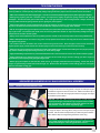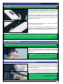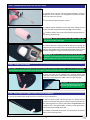
1
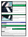
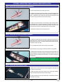
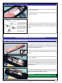
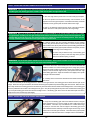
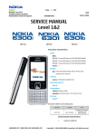
Due to production changes
and refinements, the photos
in this Assembly Manual
may differ from the actual
production model.
The ASM P-61 features advanced lightweight construction giving the model great scale shape and details while maintaining a lighter weight for a better flying
scale model. The P-61 comes from the box built and covered, leaving only final assembly and radio/engine/optional retract installation. In the air, the P-61 flies as
easy as most .60 size airplanes. The P-61 can be finished with working retract doors and beautiful aluminum-frame air-retracts with oleo struts (sold separately).
These features allow the pilot to truly achieve a scale look both in the air and on the ground.
ASSEMBLY INSTRUCTIONS
A Semi-Scale ARF R/C Model of the USA's First Specifically-Designed Night Fighter
History of the P-61 Black Widow
The heavily-armed Black Widow was the USA's first
aircraft specifically designed as a night-fighter. In the
nose, it carried radar equipment which enabled its crew
of two or three to locate enemy aircraft in total darkness
and fly into proper position to attack.
asm P-61 Black Widow specifications and features
Wing Span: 79.5 Inches (2019mm)
●
●
●
●
The XP-61 was flight-tested in 1942 and delivery of ●
production aircraft began in late 1943. The P-61 flew
its first operational intercept mission as a night fighter
in Europe on July 3, 1944, and later was also used as
a night intruder over enemy territory. In the Pacific, a
Black Widow claimed its first "kill" on the night of July 6,
1944. As P-61s became available, they replaced interim
Douglas P-70s in all USAAF night fighter squadrons.
During WW II, Northrop built approximately 700 P-61s;
41 of these were -C variants manufactured in the summer
of 1945 offering greater speed and capable of operating
at higher altitude. Northrop fabricated 36 more Black
Widows in 1946 as F-15A unarmed photo-reconnaissance
aircraft.
Wing Span: 66ft (20.1m)
●
Made in China
●
Length: 59.5 Inches (1511mm)
Weight RTF: 13.75 Pounds (6.2kg) with Retractable Landing Gear and Doors
Wing Loading: 31 Ounces Per Square Foot (95gr/dm2)
●
●
●
●
Advanced Lightweight Construction and Scale Outline
●
Parts Prepainted and Precovered in Scale Color Scheme
●
Machined-Aluminum Phneumatic Retracts and Oleo Struts Available
●
Landing Gear Doors and Actuators Included
●
●
●
●
Functions: Ailerons, Elevator, Rudders, Flaps, and Throttles (Retracts Optional)
Radio Required: 5-6 Channel or More
Engines Required: 2 x .52-.61 4-Strokes or 2 x .45-.52 2-Strokes
Large Size, Yet Easy to Fly
Strong, Prebent Wire Landing Gear and Lightweight Stand-Off Scale Wheels
Includes a Generous Hardware Package
Easy Assembly - Over 50 High-Resolution Digital Photos to Guide You
Length: 49ft 7in (14.1m)
Gross Weight: 35,853lb (16,260kg)
Maximum Speed: 425mph (684km/h)
Wing Area: 1010 Square Inches (65.42dm2)
●
Height: 14ft 8in (4.4m)
●
Engines: 2 x Pratt & Whitney 2100hp R-2800 Radials
Range: 1,200mi (1932km)
●
Service Ceiling: 46,200ft (14,081m)
All Contents Copyright © 2006 Advanced Scale Models Version 1 October 2006
Kit Product Number ASM004
CUSTOMER SERVICE INFORMATION
In the USA
In the EU
Global Services
18480 Bandilier Circle
Fountain Valley, CA 92708
Phone: (714) 963-0329
Fax: (714) 964-6236
Email: [email protected]
Ripmax Ltd.
241 Green Street
Enfield, U.K. EN3 7SJ
Phone: (0) 20 8282-7500
Fax: (0) 20 8282-7501
Email: [email protected]
In Australia
Model Engines (Aust.) PTY. LTD.
P.O. Box 828, Noble Park,
VIC., 3174
www.modelengines.com.au
SAFETY WARNINGS
This R/C Model is Designed for Experienced Pilots Only! If You are Not an Experienced pilot
Comfortable with Flying High-Performance Model Aircraft, Do Not Continue.
Like the model, These Instructions are Written with the Experienced Modeler in Mind. All
Major Steps are Outlined; However, the INSTRUCTIONS ARE Written Keeping in Mind That You're
Experienced in Basic Model Assembly Techniques and Aircraft Setup. IF YOU HAVE QUESTIONS
DURING ASSEMBLY, PLEASE CONTACT YOUR LOCAL DISTRIBUTOR using the customer service
information above.
This R/C airplane is not a toy! If misused or abused, it can cause serious bodily injury and/or damage to property. Fly only in open areas and
preferably at a dedicated R/C flying site. We suggest having a qualified instructor carefully inspect your airplane before its first flight. Please
carefully read and follow all instructions included with this airplane, your radio control system and any other components purchased separately.
ADDITIONAL ITEMS NEEDED TO COMPLETE ASSEMBLY
1 x 5 - 6 Channel or More Radio Control System
●
2 x .52 - .61 4-Stroke Engines and 12 x 6" or 13 x 6" Propellers
●
2 x .46 - .52 2-Stroke Engines with Pitt's Mufflers (Optional)
●
2 x High-Torque, Low-Profile Servos for Ailerons
●
2 x High-Torque, Standard Servos for Flaps
●
5 x Standard Servos for Throttles, Rudders and Steering
●
1 x 24" and 36" Servo Extension Leads for Elevator Servo
●
6 x 12" Servo Extension Leads for Aileron and Flap Servos
●
4 x 12" Servo Extension Leads for Throttle and Rudder Servos
●
4 x Y-Harnesses for Ailerons, Flaps, Rudders and Throttles
●
1 x 5 Cell (6 Volt) 1100mAH or greater Capacity Receiver Battery
●
2 x Remote Fueling Valves
●
Five and Thirty Minute Epoxy
●
Thin and Thick C/A
●
C/A Debonder and Rubbing Alcohol
l
Because of the number of servos and servo extension leads used, we strongly suggest
the use of a 5 cell (6 Volt) 1100mAH or greater capacity receiver battery.
As an alternative to purchasing multiple servo extension leads, you may want to purchase a
bulk spool of servo wire and connectors and make your own custom-length extension leads.
Assorted Modeling Tools (i.e., Modeling Knife, Screwdriver, Hex Wrenches, Etc.)
●
Assorted Modeling Supplies (i.e., Sandpaper, Sanding Block, Airplane Stand, Paper Towels, Etc.)
●
Optional Phneumatic Retract Installation
1 x ASM Retract Set and Control System for P-61 Black Widow (P/N ASM-ARS03)
1 x ASM Landing Gear Strut Set for P-61 Black Widow (P/N ASM-CSS02)
●
1 x Standard Servo for Retract Air Control Valve
●
l
TIPS FROM THE PROS
During the covering process, color may sometimes smear slightly from the seams. If you see any smeared colors on the
covering material, it can be quickly removed by simply wiping it off with a paper towel and a small amount of Acetone.
●
Make sure to test-fit the parts before applying glue. This will ensure that the parts fit together properly before gluing them together.
●
When gluing anything that has a smooth surface, it's important to lightly roughen the gluing surfaces with 220 grit
sandpaper. This will allow the glue to stick better. Also, never glue directly to the covering material. Always remove the
covering material from the gluing surfaces prior to gluing the parts together.
●
When cutting away the covering material from the gluing surfaces, be careful to cut only through the covering material.
Try not to cut down into the balsa structure because that can compromise the integrity of the airframe.
●
We do not suggest storing your airplane in an extremely hot environment (like the back of your car in direct sunlight) for
any length of time. The extreme heat could cause the covering material to wrinkle or sag and possibly damage the fragile
components of the radio control system.
●
Epoxy can be cleaned up before it dries using rubbing alcohol, and C/A can be cleaned up before it dries using C/A Debonder.
●
Make a U-Shaped bend in one end of a long piece of scrap pushrod wire and use it to help pull the servo extension leads
through the wing panels.
l
The control horns are mounted to the control surfaces using wood screws. Even though the wood screws thread into
plywood plates, apply a small amount of 5 minute epoxy to each screw before you install it for extra security.
l
When you plug servo extensions onto the servo leads, apply masking tape or heat-shrink tubing over the plugs to prevent
any chance of them pulling apart during assembly, or worse, during flight.
l
Apply threadlocking compound to any screws that thread into metal. This will ensure the screws can't vibrate loose during flight.
l
Apply lightweight oil or petroleum jelly to the pivot point of the rudder hinges and the landing gear door hinges (if
applicable) to prevent epoxy from gluing the hinges solid.
l
Before flying the airplane for the first time, make sure to go through and double-check everything. Check that all the
hinges are glued solidly, all bolts and screws are tight, etc. Double-check the operation of the landing gear, too, if using the
optional retractable landing gear.
l
ADVANCED SCALE MODELS P-61 BLACK WIDOW FINAL ASSEMBLY
Step 1: HINGING THE AILERONS AND FLAPS
❑ Hinge the ailerons to the wing panels, using the six C/A-style hinges
provided and a generous amount of thin C/A. Make sure that the tip of
each aileron is even with the wing tip and that the hinge gap is as tight
as possible to prevent flutter.
PRO TIP Push two T-Pins through the center of each hinge to
help keep the hinges centered while you hinge the ailerons. Make
sure to remove the T-Pins before you push the ailerons into their
final positions. This will ensure a tight hinge gap.
❑ Hinge the flaps to the wing panels, using the four C/A-style hinges
provided. Use the same techniques that you used to hinge the ailerons.
Notice that the flaps are hinged along the bottom of the wing.
IMPORTANT The inboard edge of the flaps should be approximately
1/16" (1.6mm) inside the root rib of the wing panels. This will prevent
the flaps from hitting the center wing panel when lowered.
Step 2: iNSTALLING THE AILERON and flap CONTROL LINKAGE assemblies
IMPORTANT You may need to trim the servo mounting rails and/or the servo cutout in the outer wing panel to fit your servos.
❑ Install one aileron servo into each wing panel. Each servo output
shaft should be toward the leading edge. You will need to install a 12"
long servo extension lead to each servo and run it through the wing.
❑ Install the control linkages, using two threaded pushrod wires, two
control horns, two clevises and four wood screws provided. Each
control horn should be positioned approximately 4-1/4" (108mm) out from
the inboard edge of the aileron.
❑ Install one flap servo into each wing panel. Each servo output shaft
should be toward the trailing edge.
❑ Install the control linkages, using two threaded pushrod wires, two
control horns, two clevises and four wood screws provided. See the
important note below about positioning the flap control horns.
IMPORTANT The control horn on the left wing panel should be positioned approximately 6" (152mm) out from the inboard edge of
the flap and the servo arm should point toward the wing tip. The control horn on the right wing panel should be positioned approximately
4-3/8" (111mm) out from the inboard edge of the flap and the servo arm should point toward the root end. Having both servo arms
point in the same direction will allow you to use a standard Y-Harness and still make both servos move the same direction.
Step 3: iNSTALLING THE engines
IMPORTANT The engine mounting beams are adjustable to fit the width of different sized engines. Make sure when you
adjust the width of the mounting beams to fit your engines that you keep the mounting beams centered on the firewall.
❑ Install one engine mount assembly and one engine onto each fuselage
boom, using the socket-cap screws, machine screws, washers and nuts
provided. A four-stroke engine is shown. Installing a two-stroke engine
will be the same.
IMPORTANT Each engine's drive washer should be 4-1/2"
(114mm) out from the firewall to line up correctly with the
cowlings. Note that the engines should be mounted on their
sides, toward the right side of the fuselage booms, too.
Step 4: iNSTALLING THE throttle control linkage assemblies
❑ Install your throttle servos and connect the throttle linkages, using the
pushrod wires and adjustable connectors provided. If you're using
two-stroke engines, you will need to adjust the location of the throttle
pushrod wire accordingly.
☞Install the adjustable connectors 1/2" (13mm) out from the center of the
servo arms to prevent the pushrods from interfering with the fuel tanks.
IMPORTANT Make sure that you install and connect both throttle
linkages exactly the same way, so that both throttles will be synced
as closely as possible during flight.
PRO TIP Apply a drop of thin C/A to the nut on each adjustable
connector to keep them from coming loose during flight.
Step 5: assembling and installing the fuel tanks
❑ Assemble each of the two fuel tank stopper assemblies, using one
straight tube and one 90º tube. The straight tube is the fuel pick-up tube
and the 90º tube is the vent tube.
+One of the 90º tubes included is not used.
❑ Install the stopper assemblies into the fuel tanks, making sure that
the 90º vent tubes are positioned toward the top of the fuel tanks.
☞Check the lettering on the side of the fuel tanks to determine the top.
The lettering should face up.
IMPORTANT Double-check to make sure that the clunks can
move freely inside the fuel tanks.
❑ Install the fuel tanks, making sure that the tops of the fuel tanks are
toward the tops of the fuselage booms. The front of each fuel tank should
fit firmly in the predrilled hole in the firewalls and the back of each fuel tank
should be angled down enough to clear the wing when it's mounted.
IMPORTANT Make sure to secure the fuel tanks firmly into place
and double- check that they don't interfere with the throttle linkages.
Silicone sealant works well to secure the fuel tanks into place.
Step 6: hinging the rudders
Both rudders have a preinstalled plywood control horn mounting plate in the lower inside surface. You can see it just under the
covering material. Make sure that when you hinge the rudders, that the plywood plate is toward the inside of each fuselage boom.
❑ Hinge one rudder to each fuselage boom, using two plastic hinge
points and 5 minute epoxy. Make sure to push the hinges' pivot points
completely into the notch in the rudder to ensure a tight hinge gap.
IMPORTANT Apply petroleum jelly or
machine oil to the hinge pivot points to
keep from gluing the hinges solid.
Step 7: Installing the rudder control linkage assemblies
❑ Cut out the molded rudder pushrod exit slot in the back of each fuselage boom.
q Slide one pushrod guide tube through each slot, making sure that
the front of each guide tube passes through the space just below the
wing mounting plate, then glue the guide tubes to only the back of the
fuselage for now. Allow approximately 1" (25mm) of each guide tube to
extend out from the fuselage boom side.
q Install the two threaded pushrod wires, two control horns, two clevises
and four wood screws provided.
❑ Install your rudder servos into the servo trays. Notice the position of
the servo output shafts. They should be toward the back of the fuselage.
❑ Make a Z-Bend in the pushrod wires and connect them to the servo arms.
q Glue the front of the pushrod guide tubes to the bottom of the wing
mounting support bulkheads.
Step 8: Installing the main landing gear
IMPORTANT This step details the installation of the included fixed main landing gear. If you will be installing retractable
landing gear, please skip ahead to page 13.
q Install one plywood mounting plate onto the landing gear mounting
rails in each fuselage boom, using the eight large wood screws provided.
The front edge of each mounting plate should be 3/4" (19mm) behind the
front bulkhead.
IMPORTANT There is one right and one left mounting plate. Make
sure that you install each mounting plate so that the predrilled hole in
the landing gear mounting slot is toward the inner mounting rail.
q Drill a 13/64" diameter hole through the landing gear mounting rail,
using the predrilled hole in each landing gear mounting slot as a guide.
q Insert the landing gear wires into the mounting slots and secure them
into place, using the four landing gear mounting straps and eight small
wood screws provided.
IMPORTANT The coil in each landing gear wire should be toward
the back of the fuselage booms.
q Install the wheels, using the two wheel collars and two machine
screws provided.
Step 9: Installing the cowlings
❑ Install three cowl mounting brackets onto each fuselage boom, using
the six smaller wood screws provided. Make sure that the brackets are
flush with the fuselage boom sides and that the U-Shaped side is toward
the outside.
IMPORTANT Position one bracket at the 12
O'Clock position, one bracket at the 8 O'Clock position
and one bracket at the 4 O'Clock position.
❑ Test-fit and cut out each cowling for your engines and mufflers. When aligned properly, the back edge of each cowling should overlap
the firewall 1-1/4" (32mm). For our four-stroke engine installation, we routed the mufflers out the bottom center of each cowling.
❑ Locate and drill 5/32" diameter holes through each cowling for the mounting screws.
q Install a remote fueling valve into each cowling to make it easy to fuel
the airplane, then install the cowlings to the fuselage booms, using the
six large wood screws provided.
❑ Install your propellers and each spinner, using
the two sheet metal screws provided.
Step 10: Installing the nose gear
IMPORTANT This step details the installation of the included fixed nose gear. If you will be installing retractable landing
gear, please skip ahead to page 13.
❑ Install the nose gear onto the nose gear mounting rails in the center
fuselage pod, using the four large wood screws provided. The front edge
of the nose gear mounting base should be pushed up against the forward
bulkhead.
q Install the wheel, using the wheel collar and machine screw provided.
Step 11: Installing the steering control linkage assembly
❑ Fit and glue the plywood servo tray into the slot in the forward and
center bulkheads.
IMPORTANT The steering servo cutout should be toward the front of the fuselage.
❑ Cut the length of pull-pull cable in half and secure one end of each
cable to each of the steering couplers, using two of the crimp collets
provided.
IMPORTANT Apply a drop of
thin C/A to the crimp collets for
an extra measure of security.
❑ Install your steering servo into the servo tray. Notice the position of
the servo output shaft. It should be toward the back of the fuselage.
❑ Connect the pull-pull cables to the servo arm, using the two threaded
couplers, two crimp collets and two clevises provided.
IMPORTANT Make sure that the pull-pull cables are adjusted tautly,
but not so tight that they put strain on the servo or nose gear.
Step 12: Installing the cockpit deck and window glass
IMPORTANT If you are installing the optional retractable landing gear and landing gear doors, do not install the cockpit
deck and forward window glass until after installing the nose gear retract and landing gear door assemblies. You need to
have access through the cockpit to install the landing gear doors.
❑ Fit and glue the plywood cockpit deck into the slots in the three forward
bulkheads. When positioned properly, the back edge of the cockpit deck
should be flush with the back of the rear-most bulkhead (wing mounting
bulkhead).
❑ Cut out the forward window glass along the molded scribe line.
q Install the window glass into the fuselage and glue it securely into
place.
IMPORTANT You'll need to squeeze the window glass to slide it
through the opening in the wing mounting bulkhead.
❑ Cut out and install the rear window glass, using the same techniques
that you used to cut out and install the forward window glass.
❑ Glue the glass cone to the back of the fuselage.
Step 13: hinging the elevator
IMPORTANT The elevator has a preinstalled plywood control horn mounting plate. You can see it just under the
covering material. Make sure when you hinge the elevator that the plywood plate is toward the bottom of the stabilizer
and that it's lined up with the slot in the servo mounting hatch cover in the bottom of the stabilizer.
❑ Hinge the elevator to the stabilizer, using the four C/A-style hinges
provided and a generous amount of thin C/A. Make sure that the elevator
is centered between the tips of the stabilizer and that the hinge gap is as
tight as possible to prevent flutter.
IMPORTANT The tips of the elevator will not be even with the tips
of the stabilizer. Make sure that the elevator is centered so that it
won't hit the fuselage booms when the stabilizer is installed.
Step 14: INSTALLING THE ELEVATOR CONTROL LINKAGE ASSEMBLY
IMPORTANT Make sure that you center both the elevator servo and the servo arm before installing your servo.
❑ Mount your elevator servo to the servo mounting hatch cover, using
the two plywood blocks provided.
☞The servo arm should be centered in the slot in the hatch cover.
❑ Attach a 36" (914mm) long servo extension to the servo, then run it
through the left half of the stabilizer.
IMPORTANT Cut a notch in the bottom of the stabilizer where the
servo extension exits, just large enough to fit the servo extension.
This notch will prevent the servo extension from being pinched
when the stabilizer is mounted to the fuselage boom.
❑ Install the servo hatch cover, using the four small wood screws
provided.
❑ Install the control linkage, using the threaded pushrod wire, small
control horn, clevis and two wood screws provided.
Step 15: INSTALLING THE stabilizer and the center wing panel
IMPORTANT Below we show the layout of the servo extensions. We've done it in a way to make it more convenient
when assembling the airplane. All the servo leads feed into the center fuselage pod, where the receiver will be located.
The servo leads then run through the center wing panel and into each of the fuselage booms to plug into the throttle,
rudder and elevator servos. Other servo leads run through the center wing panel and out to the tips to plug into the aileron
and flap servos. This allows easy plug-in installation of all the servo leads when assembling the fuselage booms, center
fuselage pod and the outer wing panels. All the servo extension leads stay in the center wing panel.
❑ Glue the two plywood wing-screw doublers to the top of the center
wing panel, making sure to line up the predrilled hole in each doubler with
the predrilled holes in the center wing panel.
+The straight edge of each doubler should be toward the trailing edge
of the wing.
❑ Three holes are precut in the bottom of the center wing panel to run
your servo extension leads through. The hole in the top of the center
wing panel is for the optional retract air lines. Run the servo extensions
through the center wing panel as listed below:
Elevator: One 24" extension from outer hole (left side) to center hole
Rudders: One Y-Harness and two 12" extensions from center hole to outer holes
Throttles: One Y-Harness and two 12" extensions from center hole to outer holes
Ailerons: One Y-Harness and two 12" extensions from center holes to tip
Flaps: One Y-Harness and two 12" extensions from center holes to tip
❑ Feed the elevator servo extension down through the slot in the left
fuselage boom and into the landing gear bay.
IMPORTANT You may need to adjust the size of the precut slot
in the fuselage boom to prevent pinching the servo extension.
❑ Bolt the stabilizer to the fuselage boom, using one long machine screw
provided.
IMPORTANT There is a blind nut preinstalled in the end of
the stabilizer for the machine screw, although it's difficult to
see. Also, make sure that the servo extension wire is not pinched
between the stabilizer and the fuselage boom.
❑ Plug the throttle, rudder and elevator servo leads from the fuselage
boom into the servo extensions in the center wing panel, then install the
center wing panel onto the fuselage boom, using one shorter socket-cap
screw and washer provided.
❑ Install the second fuselage boom to the center wing panel and the
stabilizer, using the second long machine screw, shorter socket-cap screw
and washer provided. Make sure to securely tighten the mounting screws.
❑ Glue the two forward fuselage boom fairings to the center wing panel,
making sure not to get any glue between the center wing panel and the
fuselage booms.
❑ Glue the two rear fuselage boom fairings to the center wing panel,
making sure not to get any glue between the center wing panel and the
fuselage booms.
IMPORTANT There are right and left rear fuselage boom fairings.
Double-check that you install them correctly.
Step 16: INSTALLING THE battery, receiver and switch
❑ Install your battery, receiver and switch into the center fuselage pod.
IMPORTANT Depending on where your airplane balances, you may
need to mount the battery in a different location. If you're using the
optional retracts, the air tank will mount in the back of the fuselage.
☞We ran the antenna out the bottom of the fuselage and secured it to
the bottom of the stabilizer.
10
Step 17: mounting the center fuselage pod
❑ Plug the servo leads into your receiver and mount the center fuselage
pod to the center wing panel, using the two longer socket-cap screws
and two washers provided.
IMPORTANT You'll need to plug a Y-Harness between the steering servo and the rudder Y-Harness. Double-check that
the nose gear moves the same direction as both rudders.
Step 18: installing the hatch cover
❑ The hatch cover is held in place using two hatch latches - one
centered at the front and one centered at the back. Install them by cutting
a slot through the top of the hatch cover for the
latch handle and drilling a hole for the latch pin
through the plywood support bulkheads. Check
the fit for smooth operation, then glue them to
the inside of the hatch cover.
❑ Locate the positions of the latch pins onto the front and rear wing
mounting bulkheads, then drill holes through the bulkheads for the pins
to slide into.
❑ Install the hatch cover and double-check that the hatch latches hold
the hatch cover securely in place.
Step 19: installing the outer wing panels
❑ Slide one aluminum wing joiner tube into one outer wing panel until
the tube bottoms out.
❑ While holding the wing joiner tube in place, drill a 7/64" diameter hole
through the wing joiner tube, using the predrilled hole in the bottom of
the wing panel as a guide.
11
❑ Carefully thread one flange-head machine screw through the predrilled
hole and into the aluminum wing joiner tube. Tighten the screw gently.
Be careful not to overtighten it or you might strip the aluminum.
IMPORTANT The machine screw will cut threads into the softer
aluminum without a problem. If you want to, you could use a 3mm
tap to cut the threads, but it's not really necessary.
❑ Firmly push one outer wing panel tightly up against the center wing
panel.
❑ Repeat the previous procedures to install one flange-head machine
screw into the center wing panel.
❑ Repeat the previous procedures to install the second outer wing panel to the center wing panel, using the remaining two flangehead machine screws provided.
PRO TIP When you disassemble the wing panels, we suggest leaving the wing joiner tubes installed in the center wing panel.
❑ Glue the radiator scoops onto the wing assembly. The shorter radiator
scoops are glued to the center wing panel and the longer radiator scoops
are glued to the outer wing panels.
BALANCING, CONTROL THROWS AND FLYING TIPS
CENTER OF GRAVITY:
The C/G is located 3-3/4" - 4-1/8" (95mm - 105mm) back from the leading edge of the wing, measured at the sides of the center fuselage pod.
IMPORTANT If you have installed the optional retractable landing gear, make sure to balance the airplane with the landing
gear retracted.
CONTROL THROWS:
Ailerons: 7/8" (22mm) Up and 5/16" (8mm) Down
Elevator: 3/4" (19mm) Up and 5/8" (16mm) Down
Rudders: 5/8" (16mm) Right and 5/8" (16mm) Left
Flaps:
IMPORTANT The control throws are measured at the widest point
of the control surfaces.
Down As Much as Possible
FLYING TIPS:
Because the landing gear retracts rearward, there will be a change in the airplane's trim. While the change in trim is small, it is
noticeable and you should be aware of it.
●
When you deploy the flaps, the airplane will have a tendency to balloon upward and will require some down elevator trim to
counteract this. We suggest the first few times that you deploy the flaps at altitude until you are familiar with the flight characteristics of
the airplane with flaps down. You may want to program elevator/flap mixing in your transmitter so that the required amount of down
elevator is automatically commanded when you deploy the flaps.
●
12
OPTIONAL ASM RETRACTABLE LANDING GEAR INSTALLATION
Step 1: iNSTALLING THE main gear retract assemblies
❑ Remove the wheels from the main gear struts.
q Install the main gear struts into the retracts, making sure that the struts
are lined up straight and that the scissor links are toward the front of the
retracts. Tighten the large socket-cap screw and the small grub screw
in the side of each retract to lock the struts into place.
q Install one retract assembly onto the landing gear mounting rails in
each fuselage boom, using the eight large wood screws provided. The
retracts should be mounted as far forward as possible. The front of the
retract cylinders should be just behind the back of the fuel tanks.
q Reinstall the wheels onto the main gear struts.
Step 2: iNSTALLING THE Nose gear retract assembly
q Install the nose gear strut into the retract, making sure that the strut is
pushed down firmly. Tighten the large socket-cap screw against the strut,
then back it off 1/4 of a turn. The strut should be held in place securely,
yet be able to rotate smoothly.
+ Do not tighten the grub screw in the side of the retract.
q Connect one length of airline tubing to each nipple on the retract assembly, long enough to reach back into the wing saddle.
q Install the retract assembly onto the landing gear mounting rails in the
center fuselage pod, using the four large wood screws provided. The back
edge of the retract mounting bracket should be 1-1/2" (38mm) behind the
front bulkhead.
IMPORTANT The retract mounting bracket slides through a slot
in the front bulkhead, allowing it to be positioned properly.
Step 3: iNSTALLING THE air control valve
q Mount the air control valve to the center wing panel, using the four
long wood screws provided.
q Install your retract servo and connect the air control valve linkage,
using the threaded pushrod wire and clevis provided.
+Note the direction of the servo output shaft. It should be toward the
trailing edge of the wing.
13
Step 4: iNSTALLING THE air tank and fill valve
q Install the air tank into the back of the center fuselage pod, using the
plywood support provided.
q Install the fill valve onto the fuselage side, making sure to tighten the
mounting nuts securely.
Air Tank
Fill Valve
Air Control
Valve
Main Gear
Main Gear
Nose Gear
The air source is connected to the
middle nipple on the air control
valve.
The outer nipples on the air control
valve are for the UP and DOWN air
lines. It does not matter which one
is used for which purpose. The
only effect is that it changes which
position is up and which position is
down (which can be changed to the
pilot's preference by reversing the
retract switch on the transmitter).
q Connect the air lines from the retracts, air tank and fill valve to the
air control valve, using the diagram at left. Use quick-connectors on the
air lines to make it easy to connect the air lines when assembling the
airplane.
The UP and DOWN air lines are
connected with "T" Fittings.
OPTIONAL LANDING GEAR DOOR INSTALLATION
Step 1: HINGING THE main LANDING GEAR DOORS
❑ Cut two notches 1/8" (3mm) wide on the hinge side of each main
landing gear door. Position one notch 1-3/4" (44mm) behind the front
edge of each landing gear door and one notch 2" (50mm) in front of the
rear edge of each landing gear door.
q Glue two hinges to each landing gear door, making sure that the
center of each hinge pivot point is centered with the edge of the landing
gear door.
❑ Glue one balsa block underneath each hinge mounting location on
the two fuselage booms.
q Drill a 1/8" diameter hole into the fuselage and through the balsa blocks
for the landing gear door hinges. Make sure to position the holes so that
the edge of each landing gear door is flush with the outside edge of the
fuselage booms. The holes will need to be right up against the edge of
the fuselage booms.
❑ Test-fit and hinge the landing gear doors to the fuselage booms. When
aligned properly, the landing gear doors should be flush with the fuselage
booms when closed and they should pivot freely.
IMPORTANT You may need to sand the outer edges of the doors
to prevent them from hitting each other when closed.
14
Step 2: Installing the main landing gear door actuators
IMPORTANT The wire leg on one side of each prebent wire bracket assembly is longer than the other leg. When
assembling the main landing gear door actuators, make sure to make one right and one left.
❑ Glue one hinge into the precut slot in one end of each plywood plate.
q Glue one prebent wire bracket assembly onto the bottom of the
opposite end of each plywood plate. Each bracket assembly should be
centered over the plywood plate and flush with the back edge.
q Drill a 1/16" diameter hole through the center of each plywood plate.
Position each hole 1-3/8" (35mm) back from the hinged edge.
IMPORTANT When you install the landing gear door actuator assemblies in the next procedure, make sure to install
the right actuator assembly into the right fuselage boom and the left actuator assembly into the left fuselage boom. It's
important that the shorter leg on the wire bracket assemblies is toward the inside of the fuselage booms. Also note that
the hinge should be toward the bottom of the plywood plate when mounted.
❑ Install the landing gear door actuator assemblies into the fuselage
booms, using the four wood screws provided. The front of each plywood
plate should be 5/16" (8mm) down from the top of the landing gear bulkhead
and the inside edge of each plywood plate should be 3/8" (10mm) from the
inside edge of the fuselage boom.
q Drill a hole just below the top of each landing gear
bulkhead 1/8" (3mm) in from the edge of the plywood
plate, then install the spring, as shown.
IMPORTANT Two of the four plastic actuator horns are cut shorter. These shorter actuator horns should be installed
onto the shorter leg of the wire brackets on the inside of the fuselage booms.
❑ Hook the outer hole in each actuator horn over the wire brackets and
install the actuator horn onto the landing gear doors, using epoxy and the
eight wood screws provided. Position the center of each actuator horn 5/8"
(16mm) in front of the back edge and 3/4" (19mm) below the outer edge
of the landing gear doors. Angle the actuator horns slightly to line up with
the angle of the wire brackets.
q Carefully cut the wood screws off flush with the outside of the landing
gear doors.
❑ Test the functionality of the landing gear doors. When the main gear is down, the landing gear doors should be held open by the
springs. When the main gear is retracted, the wheels will hit the plywood plates and pull the landing gear doors closed. When the main
gear is fully retracted, the landing gear doors should be fully closed and flush with the outside of the fuselage booms. If the landing gear
doors are pulled below the outside of the fuselage booms, glue a 1/8" (3mm) wide plywood stop to the front and back of the landing gear
bay to keep the landing gear doors flush with the fuselage booms. If the landing gear doors need to be held wider apart when down,
gently bend the wire actuator legs apart slightly.
Step 3: Installing the nose landing gear doors
❑ Hinge the nose landing gear doors and install the actuator, using the
same techniques that you used to install the main landing gear doors
and actuators. There are only a few differences: Position each hinge
1" (25mm) in from the front and rear edges of the landing gear doors
and install the actuator assembly so that it's hinged from the top, not the
bottom, like on the main gear actuators. The bottom of the plywood plate
should be even with the bottom of the U-Shaped cutout in the bulkhead.
15
OUR GUARANTEE
Advanced Scale Models guarantees this kit to be free from defects in both material and workmanship at the date of purchase. This does not cover
any component parts damaged by use, misuse or modification. In no case shall Advanced Scale Models' liability exceed the original cost of the
purchased kit.
In that Advanced Scale Models has no control over the final assembly or material used for final assembly, no liability shall be assumed for any damage
resulting from the use by the user of the final user-assembled product. By the act of using the final user-assembled product, the user accepts
all resulting liability.
Distributed By:
In the USA
In the EU
Global Services
18480 Bandilier Circle
Fountain Valley, CA 92708
Phone: (714) 963-0329
Fax: (714) 964-6236
Email: [email protected]
Ripmax Ltd.
241 Green Street
Enfield, U.K. EN3 7SJ
Phone: (0) 20 8282-7500
Fax: (0) 20 8282-7501
Email: [email protected]
16
In Australia
Model Engines (Aust.) PTY. LTD.
P.O. Box 828, Noble Park,
VIC., 3174
www.modelengines