1
Programming Support Tool
WINCAPSIII GUIDE
Copyright © DENSO WAVE INCORPORATED, 2008-2011
All rights reserved. No part of this publication may be reproduced in any form or by any means without permission in
writing from the publisher.
Specifications are subject to change without prior notice.
All products and company names mentioned are trademarks or registered trademarks of their respective holders.
Preface
Thank you for purchasing our programming support tool, WINCAPS III.
WINCAPS III is a package for efficiently developing and validating robot operation programs (PACs). It permits
checking of robot operation, variables, and I/O from a computer connected to the robot controller. It also supports
managing program files as projects, storing frequently used programs in program banks, and various other program
management functions.
Before using WINCAPS III, read this manual carefully to safely get the maximum benefit from your WINCAPS
III system.
After you have finished reading this manual, keep it handy for speedy reference.
Important
To ensure operator safety, be sure to read the precautions and instructions in "SAFETY PRECAUTIONS."
How this book is organized
This book consists of the following.
Chapter 1 Overview
Describes the WINCAPS III features, product components, operating environment, and installation procedure.
Chapter 2 Basic Functions and Operational Flow
Describes the basic functions, operational flow and editor categories of WINCAPS III.
Chapter 3 Starting Up/Shutting Down
Describes the WINCAPS III starting-up and shutting-down procedures, its windows, tools and menus.
Chapter 4 Creating a Project
Describes project creation methods, settings and data processing.
Chapter 5 Writing Programs
It also describes the auxiliary functions and control functions for program creation.
Chapter 6 Arm 3D View Window
Describes operation of arm 3D viewing and handling 3D data to check for collisions with peripheral equipment.
Chapter 7 Online Functions
Describes the online functions (monitoring and debugging) of WINCAPS III. Describes monitor functions for
checking robot status and debugging functions to directly debug robot controller programs on your PC.
Chapter 8 Logging
Describes the log functions of WINCAPS III. Describes error logs, operation logs, control logs and other types
and log acquisition timing using such devices as error triggers.
Chapter 9 Vision Manager
Describes vision functions using the µVision optional viewing device for WINCAPS III.
Chapter 10 Appendices
Contains related information.
CONTENTS
CONTENTS
Chapter 1 Overview ............................................................................ 1
1.1
1.2
1.3
WINCAPS III Features .......................................................................................... 1
Robot Controller and WINCAPS III Versions ........................................................ 1
Product Components and Operating Environment................................................ 2
1.3.1
1.3.2
1.3.3
1.3.4
1.3.5
1.4
2
2
2
3
3
Installing WINCAPS III .......................................................................................... 4
1.4.1
1.4.2
1.4.3
1.4.4
1.5
Product components.....................................................................................................
Operating environment .................................................................................................
License certificate and user registration .......................................................................
WINCAPS III trial and light versions .............................................................................
Note on languages .......................................................................................................
Before you begin ..........................................................................................................
Installing WINCAPS III..................................................................................................
Registering license .......................................................................................................
Uninstalling ...................................................................................................................
4
4
6
7
Connecting to Robot Controller ............................................................................. 8
Chapter 2 Basic Functions and Operational Flow .............................. 9
2.1
2.2
2.3
WINCAPS III Basic Functions ............................................................................... 9
Steps in Writing Robot Programs ........................................................................ 10
User Levels and Access Rights........................................................................... 12
Chapter 3 Starting Up/Shutting Down............................................... 13
3.1
Loading WINCAPS III.......................................................................................... 13
3.1.1 WINCAPS III basic settings ........................................................................................ 14
3.1.2 Programmer password ............................................................................................... 17
3.2
WINCAPS III Screen Descriptions ...................................................................... 19
3.2.1
3.2.2
3.2.3
3.2.4
3.2.5
3.2.6
3.3
Screen components....................................................................................................
Menu items .................................................................................................................
Toolbars......................................................................................................................
Docking view ..............................................................................................................
Program view..............................................................................................................
Screen operations ......................................................................................................
19
21
30
32
38
41
Quitting WINCAPS III .......................................................................................... 49
Chapter 4 Creating a Project ............................................................ 50
4.1
Overview ............................................................................................................. 50
4.1.1 Folders........................................................................................................................ 50
4.2
4.3
4.4
4.5
4.6
4.7
Creating a New Project ....................................................................................... 51
Opening an Existing Project ................................................................................ 53
Saving Project ..................................................................................................... 53
Configuring a Project........................................................................................... 54
Configuring Parameters ...................................................................................... 58
Link with Robot Controller ................................................................................... 59
4.7.1 Communications settings ........................................................................................... 59
4.7.2 Data transfers ............................................................................................................. 60
4.7.3 Arm parameter data transfer ...................................................................................... 63
4.8
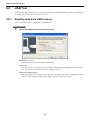
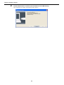
USB Tool ............................................................................................................. 64
4.8.1 Reading data from USB memory................................................................................ 64
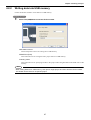
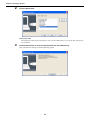
4.8.2 Writing data into USB memory ................................................................................... 67
4.9
Print ..................................................................................................................... 69
i
CONTENTS
Chapter 5 Writing Programs ............................................................. 70
5.1
5.2
5.3
5.4
Creating a New Program..................................................................................... 70
Leveraging Existing Files .................................................................................... 71
Saving a Program................................................................................................ 72
Editing a Program................................................................................................ 73
5.4.1 Finding and replacing strings...................................................................................... 74
5.4.2 Other editing functions................................................................................................ 75
5.5
Program Bank ..................................................................................................... 82
5.5.1 Adding a program to a project .................................................................................... 82
5.5.2 Adding a program to the program bank...................................................................... 83
5.5.3 Adding a category....................................................................................................... 84
5.6
Editing a Teach Pendant (TP) Panel................................................................... 85
5.6.1 Editing a TP panel ...................................................................................................... 85
5.7
Folder Functions.................................................................................................. 86
5.7.1 Creating a folder ......................................................................................................... 86
5.7.2 Importing an entire folder............................................................................................ 87
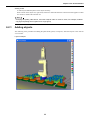
5.8
Making Executables ............................................................................................ 88
5.8.1 Checking syntax ......................................................................................................... 88
5.8.2 Making executables.................................................................................................... 89
5.9
Simulation function .............................................................................................. 90
5.9.1
5.9.2
5.9.3
5.9.4
Grammar check of simulation function .......................................................................
Simulation function and global variables ....................................................................
Precautions for simulation function.............................................................................
List of supported commands ......................................................................................
90
90
90
91
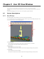
Chapter 6 Arm 3D View Window ...................................................... 92
6.1
Screen Descriptions ............................................................................................ 92
6.1.1 Arm 3D view ............................................................................................................... 92
6.1.2 Arm modeling ............................................................................................................. 95
6.1.3 Arm operation ............................................................................................................. 97
6.2
Simple Modeling.................................................................................................. 98
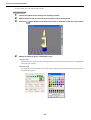
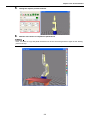
6.2.1 Adding objects ............................................................................................................ 99
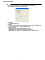
6.2.2 Saving objects .......................................................................................................... 103
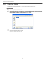
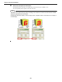
6.2.3 Importing objects ...................................................................................................... 104
6.3
Importing 3D Data ............................................................................................. 105
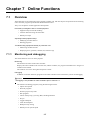
Chapter 7 Online Functions ............................................................ 107
7.1
Overview ........................................................................................................... 107
7.1.1 Monitoring and debugging ........................................................................................ 107
7.2
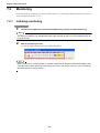
Monitoring.......................................................................................................... 108
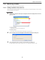
7.2.1
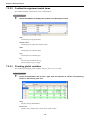
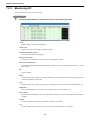
7.2.2
7.2.3
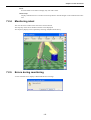
7.2.4
7.2.5
7.2.6
7.3
Initiating monitoring ..................................................................................................
Monitoring variables .................................................................................................
Monitoring I/O ...........................................................................................................
Monitoring robot........................................................................................................
Errors during monitoring ...........................................................................................
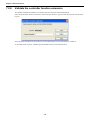
Validate the controller function extension.................................................................
108
109
112
113
113
114
Using Debugging .............................................................................................. 115
7.3.1
7.3.2
7.3.3
7.3.4
Initiating debugging ..................................................................................................
Launch the program from WINCAPS III. ..................................................................
Controller settings.....................................................................................................
Input signal dummy operation ..................................................................................
115
118
119
120
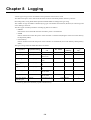
Chapter 8 Logging .......................................................................... 124
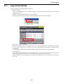
8.1
Log record timing............................................................................................... 125
8.1.1 Recording by program commands ........................................................................... 126
ii
CONTENTS
8.1.2 Error trigger log......................................................................................................... 127
8.2
Acquisition of log data ....................................................................................... 128
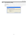
8.2.1 Log acquisition settings ............................................................................................ 129
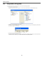
8.3
Detailed description of log types ....................................................................... 130
8.3.1
8.3.2
8.3.3
8.3.4
8.3.5
8.3.6
8.3.7
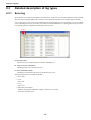
Error log....................................................................................................................
Operation log ............................................................................................................
Control log ................................................................................................................
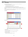
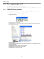
Trace logging (single / multi) ....................................................................................
Variable log...............................................................................................................
I/O log .......................................................................................................................
Joint servo log for particular joint..............................................................................
130
131
132
136
139
140
141
Chapter 9 Vision Manager .............................................................. 142
9.1
Overview ........................................................................................................... 142
9.1.1 Screen descriptions .................................................................................................. 142
9.2
Configuring Vision Manager .............................................................................. 145
9.2.1 Configuring lookup tables .........................................................................................
9.2.2 Editing a macro name...............................................................................................
9.2.3 Calibrating ................................................................................................................
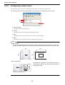
9.2.4 Configuring camera input .........................................................................................
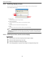
9.2.5 Switching display screens ........................................................................................
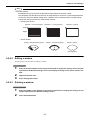
9.2.6 Editing a window.......................................................................................................
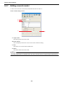
9.2.7 Editing a search model .............................................................................................
9.2.8 Registering digitization .............................................................................................
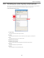
9.2.9 Calculating area, center of gravity, and principal axis ..............................................
9.2.10 Labeling ...................................................................................................................
9.2.11 Edge detection.........................................................................................................
9.2.12 Model search ...........................................................................................................
9.2.13 Reading a QR Code symbol ....................................................................................
145
146
147
152
154
155
158
161
165
168
171
176
179
Chapter 10 Appendices .................................................................... 181
10.1 List of Prohibited Characters ............................................................................. 181
10.2 Simple position correction function.................................................................... 181
iii
CONTENTS
iv
Chapter 1 Overview
1.1
WINCAPS III Features
WINCAPS III is a package for efficiently developing and validating Denso robot operation programs (PACs). It
permits checking of robot operation, variables, and I/O from a computer connected to the robot controller. It also
supports managing program files as projects, storing frequently used programs in program banks, and various other
program management functions.
1.2
Robot Controller and WINCAPS III Versions
Use the same version of WINCAPS III as that of the robot controller software.
If the WINCAPS III and robot controller software versions differ, connection may not be possible and usable functions may be limited.
• If the version of the robot controller software is more recent than that of WINCAPS III
In such cases it is necessary to update WINCAPS III with the WINCAPS III trial version that comes with the
robot set. The license is unchanged.
• If the version of the robot controller software is older than that of WINCAPS III
Ver.2.0 and higher of the robot controller can be used. However, functions not compatible with the controller
cannot be used.
In addition, match the version of the output code selected in the Project Properties (select Property from the
Project menu and use the Compile tab displayed in the dialog box) to that of the robot controller software connected to.
Note
The following functions cannot be used with versions older than Ver.2.6 of the robot controller software.
• Certain log functions (trace log (single / multi), variables log, I/O log)
• Online (debugging) functions
For versions of robot controller software prior to Ver.2.0, use WINCAPS II.
1
Chapter 1 Overview
1.3
Product Components and Operating Environment
1.3.1
Product components
Your WINCAPS III package should contain the following items.
Software
WINCAPS III Installer Product CD-ROM
License certificate
The WINCAPS III license is written on this. The reverse is a user registration card.
Instruction manual (printed versions optional)
WINCAPS III Guide (this document)
The software Help function contains the WINCAPS III Guide (this manual).
1.3.2
Operating environment
WINCAPS III requires the following computer environment to operate effectively.
Operating System
Microsoft Windows 7 (32-bit & 64-bit)
Microsoft Windows Vista
Microsoft Windows XP SP1 or later
CPU
Pentium 4 or later
Memory
512 megabytes or more
Hard disk drive
500 megabytes or more free
Others
A graphics processing unit (GPU) is recommended for displaying 3D data.
1.3.3
License certificate and user registration
1) Retaining License for Service
The User ID on the license identifies your copy of this product. It is required for after-sales service, so file the
license for future reference.
2) User Registration
User registration holds the key to our efforts to provide the best possible after-sales service. Registration ensures timely arrival of notification of technical enhancements and upgrade availability.
Procedure
To register as a user, use the web address given on license.
2
Chapter 1 Overview
1.3.4
WINCAPS III trial and light versions
WINCAPS III is available in the trial and light versions in addition to the product version.
Trial and Light Versions
WINCAPS III Light version
Difference from Product Version
• This comes with the optional mini-pendant purchased.
• Unavailable functions
Printing, simulation function, 3D data import, monitoring interval
setting, a part of program bank
WINCAPS III Trial version
• This comes with the robot set purchased.
• Unavailable functions
Only a program named "PRO1.pac" is editable.
Note
• The trial and light versions show "Trial" and "Light" on the status bar at the bottom of the screen,
respectively.
• Entering the license key of the product version to the trial or light version makes it available as a
product version.
1.3.5
Note on languages
Use the same language for WINCAPS III and the robot controller.
Otherwise, different encodings can lead to the following problems when receiving data from the robot controller,
when opening projects, etc.
• Editing and saving programs or string variables with garbled text can corrupt data.
• Project and file names can be garbled, making it impossible to open the project.
3
Chapter 1 Overview
1.4
Installing WINCAPS III
1.4.1
Before you begin
Always uninstall any existing WINCAPS III versions before installing a new version on your computer.
For the procedure, refer to 1.4.4 "Uninstalling" (P. 7).
Note
Be sure to shut down all other applications before installing or uninstalling this software.
1.4.2
Installing WINCAPS III
The following is the procedure for installing this software.
Operating procedure
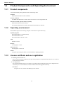
1.
2.
First shut down all Windows applications.
Load the installer.
Insert the product CD into the computer CD-ROM drive and wait for the following set-up screen to appear.
Note
If the set-up screen is not displayed, right-click on the CD-ROM drive under My Computer and choose
Open on the menu that appears. Double-click on setup.exe on the CD-ROM file list to display the setup screen.
4
Chapter 1 Overview
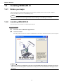
3.
Press the install WINCAPS III button to display the WINCAPS III - InstallShield Wizard dialog box.
Follow the screen instructions to configure the installation.
There are three items to specify.
1) Acceptance of the end user license agreement (EULA)
2) License key input
3) Select the folder where the program is installed.
Note
The installer may take a while before starting installation of WINCAPS III since it installs components
required for communication and 3D drawing prior to WINCAPS III.
4.
Double-check the folder specification and press the OK button.
Proceed with the install operation.
Note
Restart the computer if the installation process ends with a message advising you to do so.
If the required modules are not installed, these will be installed prior to WINCAPS III. Some modules
may require you to restart the computer; return to WINCAPS III installation after having done so.
5
Chapter 1 Overview
1.4.3
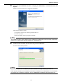
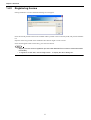
Registering license
During installation a License Information dialog box will appear.
Enter the user ID printed on the license included with the product to the License Key field, and press the Add button.
Input the license key printed on the installation disc label for Light or Trial versions.
If the user ID appears under License Key, press the Close button.
Note
• Skipping over this license registration process loads WINCAPS III in test drive mode with limited
functionality.
• To register at a later date, choose Help|License... to display the above dialog box.
6
Chapter 1 Overview
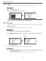
1.4.4
Uninstalling
The following is the procedure for uninstalling this software.
Operating procedure
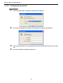
1.
2.
3.
From the Start menu, choose Settings|Control panel and then Add or Remove programs.
Choose WINCAPS III and then press the Change/Remove button to display a confirmation
dialog box.
Press the OK button to proceed with the uninstall operation.
Note
• If a dialog box appears warning of shared files, press the Leave all button.
• Installing WINCAPS III also installs ORiN2 SDK and VRC. To uninstall ORiN2 SDK and VRC, first
check that no other applications use these and then uninstall them using the same procedure as
above.
7
Chapter 1 Overview
1.5
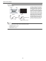
Connecting to Robot Controller
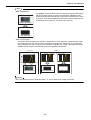
There are two ways to connect the computer to a robot controller.
Ethernet connection
This method uses an LAN interface (CN4) to connect the computer to the robot controller.
Direct connection
Robot controller
Ethernet
Crossover cable
Connection via a hub
Hub
Robot controller
Ethernet
Straight-through cables
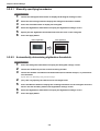
RS-232C connection
This method uses a serial port (CN1) to connect the computer to the robot controller.
Robot controller
RS-232C
Crossover cable
D-sub 9-pin connector (receptacle)
D-sub 9-pin connector (receptacle)
8
Chapter 2 Basic Functions and Operational Flow
2.1
WINCAPS III Basic Functions
The following describes the product's basic functions.
Communications
Communicating with a robot controller over an Ethernet or serial link.
Writing programs
Program using a PAC editor. For further details on programs, please refer to the programming manual.
The editor provides the following functions.
• Displaying line numbers
• Color-coded syntax highlighting
• Easy command input using an automatically scrolling list
• Automatic indenting
• Comment blocks
• Bookmarks
Program bank
This library holds programs covering handy DENSO robot functionality. For further details on programs,
please refer to Programming Manual II.
Users can customize programs registered in the program bank. They can also add their own.
Online monitoring
WINCAPS III monitors controller status, providing immediate access to variables, I/O values, and other quantities.
Online debugging
WINCAPS III shifts control from the robot controller, allowing the operator to run robot programs held in the
robot controller from the computer running WINCAPS III.
Breakpoints, Step check, and other debugging facilities allow checking variables and I/O during operation.
Arm 3D View
This is for visualizing the robot motion and posture on the PC screen. Loading 3D data or creating simple objects enables the user to check interference with the equipment and movements of workpieces and tools without
running the actual robot.
Logging
The following functions for logging variables, I/O values, and error messages are available for efficient program debugging.
• Error log
• Operation log
• Control log
• Trace log
• Variable log
• I/O log
• Single servo data log
9
Chapter 2 Basic Functions and Operational Flow
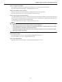
2.2
Steps in Writing Robot Programs
The following shows the WINCAPS III work flow for writing a program and validating its operation.
Step 1
Load WINCAPS III.
Step 2
Create a project.
Step 3
Write robot program.
Step 4
Teach operation positions.
Step 5
Compile executables.
Step 6
Send data to robot controller.
Step 7
Test program operation (debug).
Step 8
Back up data.
Step 9
Exit WINCAPS III.
Step 1: Load WINCAPS III.
Launch WINCAPS III.
For further details, refer to Chapter 3 "Starting Up/Shutting Down" (P. 13).
Step 2: Create a project.
This project contains all necessary data for the target robot.
For further details, refer to Chapter 4 "Creating a Project" (P. 50).
Step 3: Write robot program.
Write the robot operation program using the built-in editor.
For further details, refer to Chapter 5 "Writing Programs" (P. 70).
Step 4: Teach operation positions.
Specify operation positions by manipulating the virtual robot in the Arm 3D view window.
For further details, refer to Chapter 6 "Arm 3D View Window" (P. 92).
Note
Using simple modeling and importing 3D data creates an on-screen simulation for specifying the robot's operation range and detecting collisions with surrounding equipment.
10
Chapter 2 Basic Functions and Operational Flow
Step 5: Compile executables.
The compiler converts project programs to executables for execution by the robot controller.
For further details, refer to Chapter 5 "Writing Programs" (P. 70).
Step 6: Send data to robot controller.
Connect to the robot controller and send it the data necessary for robot operation.
For further details, refer to 4.7 "Link with Robot Controller" (P. 59).
Step 7: Test program operation (debug).
Use WINCAPS III online functions to examine program flow, determine the robot's operation range, and detect
collisions with surrounding equipment. Modify the program to eliminate any problems detected. Repeat the
compile-debug cycle until no such problems remain.
For further details, refer to Chapter 7 "Online Functions" (P. 107).
Note
• WINCAPS III directly controls robot controller program operation.
• Trace logging allows efficient validation of multitasking and other complex program flow as well
as easy analysis of interactions with other programs.
• I/O logging simplifies timing adjustments with neighboring equipment for use in optimizing operation and reducing cycle times.
Step 8: Back up data.
Use WINCAPS III to save the robot controller's internal data in projects.
For further details, refer to 4.7.2 "Data transfers" (P. 60).
Step 9: Exit WINCAPS III.
For further details, refer to Chapter 3 "Starting Up/Shutting Down" (P. 13).
11
Chapter 2 Basic Functions and Operational Flow
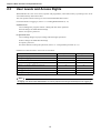
2.3
User Levels and Access Rights
WINCAPS III's two user access levels, operator and programmer, ensure data security by limiting access to advanced functionality and sensitive data.
The user specifies which on the log-in screen when WINCAPS III first starts.
For further details on logging in, refer to 3.1 "Loading WINCAPS III" (P. 13).
Operator level
Level enabling PAC program creation / editing and other basic operations.
It blocks changes to WINCAPS III settings.
It does not require a password.
Programmer level
Level enabling changes in project settings and other higher operations.
It allows changes to WINCAPS III settings.
It requires a password.
For further details on setting this password, refer to 3.1.2 "Programmer password" (P. 17).
Differences in functions due to user levels are as follows.
Function
Operator
Programmer
Creating a new project
{
{
Writing / editing programs
{
{
Data transfers
{
{
Online (monitoring/debugging functions)
{
{
Addition of controller function extension
{
{
Altering project properties
U*
{
Altering parameters
×
{
Reading / writing arm parameters
×
{
*Only communications settings can be changed
Note
Changing user levels while WINCAPS III is running requires returning to the dialog box for logging in.
12
Chapter 3 Starting Up/Shutting Down
3.1
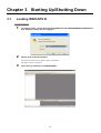
Loading WINCAPS III
Operating procedure
1.
2.
On the Start menu, choose All Programs|DENSO FACTORY WARE|WINCAPS III|WINCAPS
III to display the dialog box for logging in.
Specify user level and password.
The user level choices are 0-operator and 1-programmer.
The latter requires a password.
3.
Press the Log in button to load WINCAPS III.
13
Chapter 3 Starting Up/Shutting Down
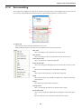
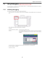
3.1.1
WINCAPS III basic settings
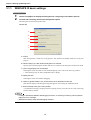
Operating procedure
1.
2.
Choose Tool|Option to display the dialog box for configuring such software options.
Click the tab containing the desired configuration option.
The dialog box has the following three tabs.
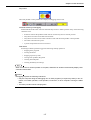
General tab
A
B
C
D
E
F
A: Project
This field specifies a folder for saving projects. This becomes the default folder for saving new
projects.
B: When loading it, the last window arrangement is restored.
Opens project with the program window and 3D view window in the same place as when last closed.
C: [Trace Log] display PAC Commands.
Selecting this check box adds a Code column displaying souce code to the Trace log window.
* Note that large logs can take considerable time to display.
D: Debug function
Selecting this check box enables debugging.
E: Values of global variable, tool, work and area when Simulation mode end
Switches the display of the dialog message that appears when exiting the simulation mode.
F: Show message when get current position.
A confirmation message is displayed when acquiring position. Turn this ON to avoid overwriting
position data by mistake.
Note
• Leaving it deselected disables all debugging functions, so selecting one during online operation
triggers an error message.
• WINCAPS III always starts with debugging disabled.
14
Chapter 3 Starting Up/Shutting Down
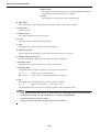
Editor tab
A
B
C
D
A: Font
This area specifies the font type and size for Program edit windows.
B: Code color
This area specifies the colors for highlighting text in the Program edit window. Select the text type,
then choose text color with Front color and surrounding color as Back color.
C: Tab
This area specifies the tabs for Program edit windows.
D: Others
Selecting this check box automatically runs a syntax check on the selected program before closing
the Program edit window. Select the check box to delete comments other than those in REM for
Adding Comments.
Communication tab
A
B
A: Monitor sampling time
This area specifies the intervals at which to monitor robot controller operation.
B: Data send option
The options in this area configure data transfers to the robot controller.
15
Chapter 3 Starting Up/Shutting Down
Arm tab
A
B
C
D
A: Moving tracks
Sets the point numbers for the robot operation trajectory displayed in the Arm 3D view window.
B: BackColor
This sets the Arm 3D View window background color.
C: Show message when collision is detected
Select to display the Collision dialog box when a collision is detected.
D: Type to display collision position
Choose the method of displaying the robot's position when a collision occurs.
3.
When configuration is complete, press the OK button.
Pressing the Cancel button instead discards all changes.
Note
Moving to another tab does not save changes. To save your new settings, always press the OK button.
16
Chapter 3 Starting Up/Shutting Down
3.1.2
Programmer password
Using WINCAPS III at the programmer level requires logging in with a password.
Register one with your first login.
Note
Passwords are case sensitive.
3.1.2.1 Registering a password
Operating procedure
1.
2.
3.
In the Login WINCAPSIII dialog box, choose 1-programmer as the user level to enable password input.
Enter the desired password and press the Login button to display the dialog box for changing the password.
Re-enter the new password in the Review new password field and press the OK button to
register the password.
17
Chapter 3 Starting Up/Shutting Down
3.1.2.2 Changing the password
Operating procedure
1.
Choose Tool|Re-Login to display the dialog box for logging in.
2.
Press the Chg. PW button to display the dialog box for changing the password.
3.
4.
Enter three passwords: the current password in the first field and the new one in the other
two.
Press the OK button to update the password.
18
Chapter 3 Starting Up/Shutting Down
3.2
WINCAPS III Screen Descriptions
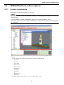
3.2.1
Screen components
WINCAPS III uses the following general screen layout.
Note
WINCAPS III offers the user considerable flexibility in rearranging screen elements to match the
needs at hand.
For further details on screen customization, refer to 3.2.6 "Screen operations" (P. 41).
The screen shots in this document use the default layout, so may not necessarily match what appears
on your screen.
A
B
C
D
A: Menus
This area displays the following ten menu items available in WINCAPS III.
• File menu
• Edit menu
• View menu
• Project menu
• Connect menu
• Debug menu
• Arm menu
• Tool menu
• Window menu
• Help menu
For further details on menu items, refer to 3.2.2 "Menu items" (P. 21).
19
Chapter 3 Starting Up/Shutting Down
B: Toolbars
This area displays the following six toolbars that provide user alternate access to most menu items with button
icons.
• Standard toolbar
• Edit toolbar
• View toolbar
• Link Mode toolbar
• Debug toolbar
• Log toolbar
For further details on toolbars, refer to 3.2.3 "Toolbars" (P. 30).
C: Docking view
The Docking view area displays various types of information windows showing the results of a project-wide
search, compile error messages, variables and I/O values, etc.
For further details on the Docking view, refer to 3.2.4 "Docking view" (P. 32).
D: Program view
The Program view area displays the source code, Arm 3D View window, etc.
For further details on the Program view, refer to 3.2.5 "Program view" (P. 38).
20
Chapter 3 Starting Up/Shutting Down
3.2.2
Menu items
The following describes each WINCAPS III menu item.
3.2.2.1 File menu
New Project
This is for creating a new project.
Open Project...
This is for opening an existing project.
Close Project
This closes the currently open project. If the project has program edits or
other unsaved modifications, a dialog box asks whether you wish to save
them.
Save Project
This saves the currently open project.
Save As Project
This is for saving the currently open project under a new name. It creates a
folder under a specified name and copies all current project data into the
folder.
Import
This is for reading in .csv files containing variables and log data exported
from other projects.
Export...
This exports variables, I/O values, and log data in standard .csv format for
use by other applications.
Save
This saves the program or header file selected in the Program view area.
Save As...
This saves the program or header file selected in the Program view area under a different name.
It adds saved file into a project.
Print...
This is for printing programs, variables, and a list of I/Os.
Recent Projects
This displays recently used projects.
Choosing one opens it.
Exit
This is for shutting down the program.
If the project has program edits or other unsaved modifications, a dialog
box asks whether you wish to save them.
21
Chapter 3 Starting Up/Shutting Down
3.2.2.2 Edit menu
Undo
This cancels the last operation, returning edits to the preceding state.
Redo
This repeats the operation canceled with Undo.
Cut
This moves to the Windows clipboard and deletes the contents selected in
the Program edit window.
Copy
This copies to the Windows clipboard the contents selected in the Program
edit window.
It does not delete the original.
Paste
This copies the clipboard contents to the selected portion of the Program
edit window.
Delete
This deletes the area selected in the Program edit window.
Select All
This selects the entire contents of the Program edit window.
Find and Replace...
This replaces occurrences of one string with another.
Jump to...
This is for moving the cursor to a line, specified by number, in the Program
edit window.
Comment Block
This submenu converts the lines selected in the Program edit window to and
from comments.
Indent
This submenu controls indenting of the lines selected in the Program edit
window
Bookmark
This is for working with bookmarks.
Insert registered string
Previously registered character strings are placed in the program.
Register string
Commonly used character strings can be registered in advance and placed
in programs through shortcuts.
Add comment
Selecting this automatically adds texts written in the application columns
of variables and I/O lists to the source code as comments.
Format code
The program code is shaped into a standard form. Line indents are inserted
and blank spaces inside the code added or deleted automatically.
Delete code for simulation
Deletes code for simulation functions.
22
Chapter 3 Starting Up/Shutting Down
Command List
Selecting this automatically displays a scrolling list of commands available
with auto-completion at the cursor position.
Insert Command
This is for inserting a command selected from the command input list at the
cursor position in the predetermined syntax.
3.2.2.3 View menu
Project View
This displays the Project view window.
Program List
This displays the Program list window.
Arm View
This displays the Arm view window.
Arm Modeling
This displays the Arm modeling window.
Arm Operation
This displays the Arm operation window.
I/O View
This displays an I/O window in the Docking view area.
Variables View
This submenu displays variables of specified types in the Docking view area.
Log View
This submenu displays Log windows of specified types in the Program
view area.
Tool/Work/Area setting
This submenu displays windows for specifying tools, work pieces, and areas.
Local
This displays local variables in the Docking view area.
Watch
This displays the Watch window in the Docking view area.
Output
This displays output in the Docking view area.
Search Result
The results are displayed when Search / replace is executed.
Vision monitor
This toggles display of the Vision monitor window.
Vision tool
This toggles display of the Vision tool window
Controller Information
This displays basic information of the controller.
ToolBar
This submenu controls the display of toolbars.
23
Chapter 3 Starting Up/Shutting Down
3.2.2.4 Project menu
Add Program...
This is for creating a new program and adding it to the current project.
Add Existing File...
This submenu is for copying the selected program into the current project
folder to add it in the project.
Enable/Disable
This submenu controls usage of a file within the project.
Enabled programs can be executables.
Folder
This submenu is for creating, renaming, and importing folders. Programs of
other projects can be imported as folders.
Create Macro Definition File
This submenu is for creating header files defining macro names of variables
and I/O ports.
Import Macro Definition File
This submenu is for reading the content of header files defining macro
names to apply it to variables and I/O ports.
Command builder
This submenu is for displaying the Command builder dialog box to support
PAC commands input.
Program Bank
This displays a dialog box with programs covering handy DENSO robot
functionality.
Developers can also add their own work to this open-ended library.
Program Template
This submenu is for creating a typical program merely by entering parameters in accordance with guidances.
Check Grammar
This runs a syntax check on the selected program. The results appear in an
Output window.
Make Executable
This updates the executables for the project. An Output window tracks
progress and error messages from the compiler.
Parameter
This displays the dialog box for specifying project parameters.
Joint Setting Table
This displays the dialog box for specifying joint settings. Axis settings are
used in SMRT4G, MC2F and Added axes.
Property
This submenu displays the dialog box containing property sheets of communication, compile, variables, and I/O items for referring to them or configuring the project.
24
Chapter 3 Starting Up/Shutting Down
3.2.2.5 Connect menu
Transfer Data...
This is for exchanging data with the robot controller.
Connect Setting
This opens the Property dialog box to the Communications settings tab, the
one for configuring the communications link for the project.
Monitor Communication
This submenu specifies the connection to the robot controller.
• Offline:
WINCAPS III operates alone, without connecting to the robot controller.
• Monitoring:
WINCAPS III connects to the robot controller and displays its internal
data. Specify the data update intervals with Tool|Option.
• Debugging:
WINCAPS III controls automatic program operation from the computer, debugging programs by modifying their variables and I/ O values as
they run.
25
Chapter 3 Starting Up/Shutting Down
3.2.2.6 Debug menu
Note
The Debug menu is available in WINCAPS III connected with the robot controller version 2.7 or later.
Simulation mode
Start the simulation function.
This enables checking of cycle time or operation posture.
Start all supervisor tasks
This starts all supervisory tasks.
Stop all supervisor tasks
This stops all supervisory tasks.
Start a task
This starts the selected program.
Step in
This executes one program step.
If a step includes CALL text, execution pauses at the first step in that function.
Continue all tasks
This resumes suspended tasks.
Halt
This suspends program execution.
Step-stop
Program execution runs through to the end of the current step.
Cycle-stop
Program execution runs through to the end of the current cycle.
Program reset
This returns the current program to its starting point.
Reset all tasks
This returns all programs to their starting points.
Show quick watch
This displays the current values of all variables and I/O ports currently selected in the Program edit window.
Register to watch
Add the currently selected quick watch items to the watch list in the Watch
window.
Delete watch
This deletes the watch items selected in the Watch window.
Set/Reset a break point
This specifies whether program execution breaks at the step currently under
the cursor in the Program edit window.
Reset all break points
This clears all breakpoints.
Break point stop setting
This specifies whether hitting a breakpoint pauses the current program only
or all programs.
26
Chapter 3 Starting Up/Shutting Down
Set line to start/stop log
One way to specify a logging range is to select it in the Program edit window. Another is to specify starting or stopping for the current line in the
Program edit window.
Get Single Trace Log
This displays the trace log for the specified program, a listing of the program steps executed and their execution times.
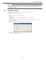
Controller settings
This submenu controls controller operation: turning motors and machine
locks ON and OFF and specifying times for reading control logs.
3.2.2.7 Arm menu
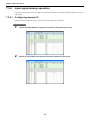
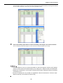
Current angle display
This submenu controls the display, in the Arm 3D View window, of current
values for arm angle variables of types P, J, T, and J-EX. It also supports
copying of those values.
Tool Coordinate Monitor
This toggles the display of the current tool number and coordinate axis in
the Arm 3D view window.
Work Coordinate Monitor
This toggles the display of the current work number and coordinate axis in
the Arm 3D view window.
Collision Detection
Selecting this toggles collision detection.
Collision Display Reset
This removes collision results from the display.
Moving tracks
Sets the display of the trajectory the flange tip moved through.
Display Enable/Disable
This submenu controls display of elements in the Arm 3D view window:
floor, arm, tool, work, area, and obstacles.
27
Chapter 3 Starting Up/Shutting Down
3.2.2.8 Tool menu
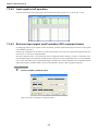
DIO Command Viewer
This displays the DIO command viewer dialog box for displaying standard
command patterns or those with mini I/O assignments. During debugging,
this dialog box also allows batch setting of command patterns for dummy
I/O.
Controller extension
This is available only in the online monitoring mode.
Simple position correction
Robot position can be corrected easily with WINCAPS III.
USB
This is for reading or writing project data from/to a USB memory.
ARM-Parameter
Reads/writes arm parameters needed for controller settings.
Re-Login
This returns to the dialog box for logging in, the only way to changing user
levels while WINCAPS III is running
Option
This displays the dialog box for configuring such software options as the
editor's syntax highlighting colors and communications time out limits.
28
Chapter 3 Starting Up/Shutting Down
3.2.2.9 Window menu
Close Window
This closes the program or header file selected in the Program view area.
Close All Windows
This closes the following Program view window types: Arm 3D view, Vision monitor, and Program edit.
Cascade windows
This stacks all windows of the above types so that they overlap each other,
with the title bars visible, in the Program view area.
Tile Horizontally
This lines up all windows of the above types horizontally in the Program
view area.
Tile Vertically
This lines up all windows of the above types vertically in the Program view
area.
Window List
This submenu lists all windows of the above types currently open in the
Program view area.
Show all hidden windows
This restores a minimized window to the original size.
Hide all
This minimizes all windows in the Docking view area to maximize the Program view area. Use this to maximize the Arm 3D view window or Program edit window.
Reset window layout
This returns windows to the default layout.
3.2.2.10 Help menu
WINCAPS III guide
This shows the WINCAPS III help.
License...
This shows the license information.
Version
This shows the version of WINCAPS III.
29
Chapter 3 Starting Up/Shutting Down
3.2.3
Toolbars
The toolbars provide user alternate access to most menu items with button icons.
Alternatively, you can save screen real estate by turning them off, all or individually.
There are six of these toolbars. The following lists map their buttons to the corresponding menu items.
Standard toolbar
A
B
C D
E
F G H
A:
New Project
B:
Open Project...
C:
Save Project
D:
Save
E:
Cut
F:
Copy
G:
Paste
H:
Delete
I:
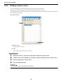
Find...
J:
Undo
K:
Redo
L:
Create Programs...
M:
Check Syntax
N:
Make Executable
I
J K
H
I
Edit toolbar
A
B
C
D
E
A:
Command List
B:
Indent
C:
Unindent
D:
Encomment
E:
Decomment
F:
Set/Clear Bookmark
G:
Next Bookmark
H:
Previous Bookmark
I:
Clear Bookmarks
F G
30
L
M
N
Chapter 3 Starting Up/Shutting Down
View toolbar
A
B
C
D E
A:
Project View
B:
Program list
C:
Arm view
D:
Arm Modeling
E:
Arm operation
Communication mode toolbar
A
B
A:
Transfer Data
B:
Monitor Communication
Debug toolbar
A
B
C
D
E
F G
A:
Simulation mode
B:
Start a Task
C:
Step In
D:
Continue All Tasks
E:
Halt
F:
Step-stop
G:
Cycle-stop
H:
Program Reset
I:
Reset All Tasks
J:
Toggle Breakpoint
H
I
J
Log toolbar
A
B
C
D
E
F
G
A:
Set/Clear Control Log Start Line
B:
Set/Clear Control Log End Line
C:
Set/Clear Trace Log Start Line
D:
Set/Clear Trace Log End Line
E:
Set/Clear Variable Log Start Line
F:
Set/Clear Variable Log End Line
G:
Single-trace Log
31
Chapter 3 Starting Up/Shutting Down
3.2.4
Docking view
The Docking view area provides tab interfaces for switching between members of windows that the user has
"docked" (grouped together).
For further details on docking procedures, refer to 3.2.6 "Screen operations" (P. 41).
Docking is available for the following window types.
• 3.2.4.1 "Project view" (P. 32)
• 3.2.4.2 "Program list" (P. 33)
• 3.2.4.3 "Arm modeling" (P. 34)
• 3.2.4.4 "Arm operation" (P. 34)
• 3.2.4.5 "I/O window" (P. 35)
• 3.2.4.6 "Variables window" (P. 35)
• 3.2.4.7 "Tool/work/area setting window" (P. 35)
• 3.2.4.8 "Local variables window" (P. 35)
• 3.2.4.9 "Watch window" (P. 36)
• 3.2.4.10 "Output window" (P. 36)
• 3.2.4.11 "Search results window" (P. 36)
• 3.2.4.12 "Vision tool window" (P. 37)
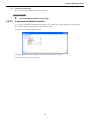
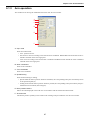
3.2.4.1 Project view
This window lists folders and files in the project.
It has buttons for adding programs, importing files, and other operations.
A B C D
E
A: Create Programs...
This button is for creating program, header, and teach pendant (TP) panel files in the project.
B: Import
This button is for adding existing programs to the project.
32
Chapter 3 Starting Up/Shutting Down
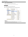
C:
button
These buttons are for moving files and folders up and down the file hierarchy.
: Move the selected item up one position.
: Move the selected item down one position.
D: Display files
This button opens a folder, displaying the files inside.
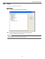
E: List hierarchy
This button lists all files and folders in the project hierarchy.
Double-clicking a program, header, or teach pendant (TP) panel file opens it.
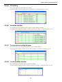
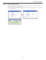
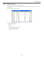
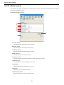
3.2.4.2 Program list
This window lists the programs in the project.
Icon
A key icon is shown for locked files.
Program name
This displays the program name declared in "PROGRAM".
File name
This displays the name of files with programs stored.
Title
This displays the program name declared in '!TITLE "xxxxx".
Usage
This displays the usage status of the program.
Status
Displays the status of the program.
Executing line
Displays the currently executing line number.
Run time
Displays the time from start to end of the program.
Priority
Displays the priority of the program.
33
Chapter 3 Starting Up/Shutting Down
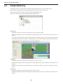
3.2.4.3 Arm modeling
This window is for arranging objects in the Arm 3D view window.
For further details on modeling in the Arm 3D view window and Arm modeling, please refer to Chapter 6 "Arm
3D View Window" (P. 92).
3.2.4.4 Arm operation
This window is for moving the simulated robot in the Arm view window.
For further details on operating the robot in the Arm view window, please refer to Chapter 6 "Arm 3D View Window" (P. 92).
34
Chapter 3 Starting Up/Shutting Down
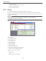
3.2.4.5 I/O window
This window type is for monitoring I/O and editing.
For further details on monitoring I/O, please refer to Chapter 7 "Online Functions" (P. 107).
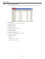
3.2.4.6 Variables window
This window type is for displaying global variables. Listing or editing is possible.
For further details on monitoring global variables, please refer to Chapter 7 "Online Functions" (P. 107).
3.2.4.7 Tool/work/area setting window
This window type is for setting tool coordinates, work coordinates and area.
For further details on these coordinates, please refer to Chapter 6 "Arm 3D View Window" (P. 92).
3.2.4.8 Local variables window
This window type is for monitoring the selected local variables.
For further details on monitoring local variables, please refer to Chapter 7 "Online Functions" (P. 107).
35
Chapter 3 Starting Up/Shutting Down
3.2.4.9 Watch window
This window type is for monitoring the values of variables on the watch list.
For further details on watch lists, please refer to Chapter 7 "Online Functions" (P. 107).
3.2.4.10 Output window
This window type displays progress and error messages from the syntax check and compiler.
For further details on such output, please refer to .5.8 "Making Executables" (P. 88)
3.2.4.11 Search results window
This window type displays the results of a project-wide search.
For further details on this output, please refer to 5.4.1 "Finding and replacing strings" (P. 74).
36
Chapter 3 Starting Up/Shutting Down
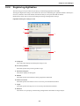
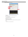
3.2.4.12 Vision tool window
This window type is for configuring visual functions.
For further details on this window, please refer to Chapter 9 "Vision Manager" (P. 142).
37
Chapter 3 Starting Up/Shutting Down
3.2.5
Program view
This displays the following window types: Arm 3D view, Vision monitor, and Program edit. If there is a robot controller on line, the list expands to include Task and Log windows.
This area provides a tab interface for switching windows.
This area displays the following window types.
• 3.2.5.1 "Program edit window" (P. 38)
• 3.2.5.2 "Arm 3D View" (P. 39)
• 3.2.5.3 "Vision monitor window" (P. 39)
• 3.2.5.4 "Log window" (P. 40)
3.2.5.1 Program edit window
This window type is for editing program and header files.
Syntax highlighting displays numbers, operators, comments, and other elements in different colors.
38
Chapter 3 Starting Up/Shutting Down
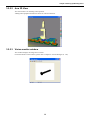
3.2.5.2 Arm 3D View
This 3D window is for checking robot operation.
Adding other equipment and devices allows for collision detection.
3.2.5.3 Vision monitor window
This window displays the image from a camera.
For further details on this window, please refer to Chapter 9 "Vision Manager" (P. 142).
39
Chapter 3 Starting Up/Shutting Down
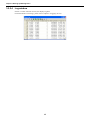
3.2.5.4 Log window
If there is a robot controller on line, this displays log data.
For further details on such logs, please refer to Chapter 8 "Logging" (P. 124).
40
Chapter 3 Starting Up/Shutting Down
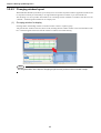
3.2.6
Screen operations
WINCAPS III allows flexible customization of menus, toolbars, and windows on the screen.
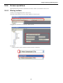
3.2.6.1 Moving toolbars
Toolbars can be dragged anywhere on the screen.
Inside the toolbar display area, they clump together to conserve space.
Dragging one outside this area, however, adds a title bar.
Procedure
To drag a toolbar, grab its end tab or title bar (shown in red below).
41
Chapter 3 Starting Up/Shutting Down
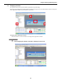
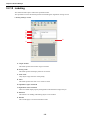
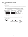
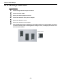
3.2.6.2 Changing window layout
WINCAPS III's flexible layout allows you to freely move its windows anywhere within its application window and
to snap them vertically or horizontally to an edge within the application window or just the selected area.
The Docking view area provides tab interfaces for switching between members of windows that the user has
"docked"—stacked together within their own display area.
(1)
Grouping window for display
Docking adds a freestanding window to another window to form or expand a group.
Just grab the first window's title bar (shown in red) and drag the blue window outline to the second window's title
bar. A tab then appears below the stacked windows to indicate successful docking.
Note
The drag destination is the title bar. Dropping anywhere else produces normal window overlap.
42
Chapter 3 Starting Up/Shutting Down
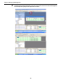
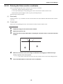
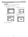
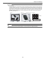
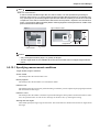
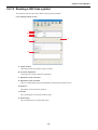
(2)
Snapping windows
This operation moves the selected window up against the specified edge.
The first step is grabbing the window's title bar to display the snap arrow icons. These offer two choices: snap within the application window or just within the current area.
Snapping within application window
Your first choice is to move windows to an edge of the application window.
Operating procedure
1.
Start dragging the window's title bar to display the snap icons.
43
Chapter 3 Starting Up/Shutting Down
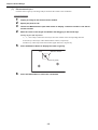
2.
Drop the blue window silhouette on an icon in the outer set to move the window against
the corresponding edge of the application window.
44
Chapter 3 Starting Up/Shutting Down
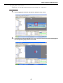
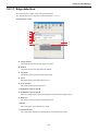
Snapping within current area
Alternatively, you can snap within the Program view, Docking view, or other area.
Operating procedure
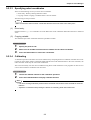
1.
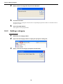
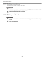
2.
Start dragging the window's title bar to display the snap icons.
Drop the blue window silhouette on an icon in the inner set to move the window against
the corresponding edge of the current area.
45
Chapter 3 Starting Up/Shutting Down
46
Chapter 3 Starting Up/Shutting Down
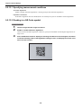
(3)
Minimizing Docking view area
This operation minimizes the Docking view area to maximize the Program view area.
Operating procedure
1.
Click the
icon on the right end of the Docking view title bar.
The operation minimizes the Docking view area, showing the tab instead as shown below.
47
Chapter 3 Starting Up/Shutting Down
2.
To temporarily display the minimized window in the Docking view area so that it overlaps
the Program view area as shown below, click the tab shown in step 1.
Note
• To minimize all windows in the Docking view area, select Window|Hide all.
• To restore a minimized window in the Docking view area to the original size, display the minimized window and click the
icon on the right end of the title bar. To restore all minimized windows to the original size, select Window|Show all hidden windows from the Window menu.
48
Chapter 3 Starting Up/Shutting Down
3.3
Quitting WINCAPS III
Operating procedure
1.
Choose File|Exit to quit the program.
Note
If a project is already being edited, the confirmation dialog appears.
The edited changes can be selected and saved by pressing Show extra information.
Save button
Overwrites the project.
Don't Save button
This button deletes the edited changes.
Cancel button
Cancels the quitting procedure and reverts to the previous WINCAPS III screen.
49
Chapter 4 Creating a Project
4.1
Overview
WINCAPS III manages the programs, parameters, variables, and other data for each robot as a separate project.
4.1.1
Folders
A project uses the following file hierarchy.
Project folder
A
Project file
B
Project data folder
C
Backup folder
D
Modeling data folder
E
Remote files folder
F
Source files folder
G
A: Project folder
This holds all files for the project.
Its name becomes the project name.
B: Project file
This file, with file extension .wpj. contains data on the project overall.
Double-clicking this file opens the corresponding project. (File extension: .wpj)
C: Project data folder
This folder holds the data for the project.
Its name becomes the project name.
D: Backup folder
This folder holds backup copies of robot controller related data including the power-on time. Receiving data
from the connected robot controller automatically creates this folder.
E: Modeling data folder
This folder holds 3D modeling data for the project.
F: Remote files folder
If there is a robot controller on line, the software spools robot controller files here.
G: Source files folder
This folder holds the programs, header files, and teach pendant (TP) panels for the project.
The Project window displays its contents.
50
Chapter 4 Creating a Project
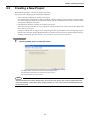
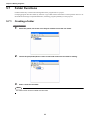
4.2
Creating a New Project
WINCAPS III provides a wizard for creating a new project.
New projects are created using the following two methods.
• Select robot type manually for creating a new project
This method can be used when the robot is not linked. Used for creating projects in advance of robot installation (when designing equipment, etc.) Match the settings with the controller to link to. Errors will occur during
linking if the settings do not match.
• Get information from the controller for creating a new project
If the robot and the controller are set up, import one of projects held in the robot controller into WINCAPS
III to create a new project.
Using this method does not require newly configuring the robot type and other various settings, but requires
that the robot controller and PC (WINCAPS III) be connected with each other for data exchange. When importing a project from the robot controller, it is possible to search for robots connected.
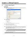
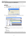
Operating procedure
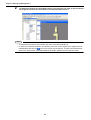
1.
Choose File|New project to load this wizard.
The Back button returns the wizard to the preceding screen.
The Next button advances the wizard to the next screen.
The Cancel button exits the wizard.
Note
Starting WINCAPS III Project wizard when the currently open project has unsaved modifications displays the following confirmation dialog, asking whether or not to save unsaved modifications before
closing the project.
51
Chapter 4 Creating a Project
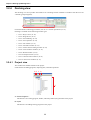
2.
Follow the wizard's instructions to configure the project.
There are six items to specify in the case of manual robot type selection.
1) Project name and location
2) Robot type
3) Robot controller options
4) Link type
5) Variables
6) I/O port settings
In the case of project creation from controller information, make settings only for 1) Project name and location, and 4) Link type
Note
• The last four can be modified at any time, but not the first three:
• Project name and location
• Robot type
• Robot controller options
• There is a basic setting that specifies where WINCAPS III saves new projects. For further details
on these settings, please refer to 3.1.1 "WINCAPS III basic settings" (P. 14).
• Do not check the Customer specifications check box displayed by Robot controller options for
standard robots. Use for robots with special specifications (with a "#" for the robot type).
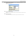
3.
When a Complete button appears on the screen, press it to display the new project.
52
Chapter 4 Creating a Project
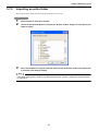
4.3
Opening an Existing Project
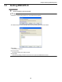
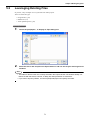
Operating procedure
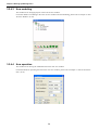
1.
Choose File|Open project to display the Open dialog box.
Note
• The following two types of files can be opened.
WINCAPS III project data (File extension: .wpj)
WINCAPS II project data (File extension: .spj)
• If an existing project is currently edited, the confirmation dialog appears, asking whether or not to
save unsaved modifications.
4.4
Saving Project
The File menu offers two ways to save the current project.
• Save project
This saves the currently open project.
• Save project as...
This creates a folder under a specified name and copies all current project data into the folder.
Note
When executing Save project as..., specify a folder name other than the current project folder name
and all folder names contained in the current project folder.
53
Chapter 4 Creating a Project
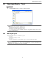
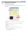
4.5
Configuring a Project
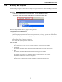
Operating procedure
1.
2.
3.
Choose Project|Properties to display the property sheets for the project.
Click the tab containing the desired configuration option for the settings.
When configuration is complete, press the OK button.
Pressing the Cancel button instead discards all changes.
Note
Moving to another tab does not save changes. To save your new settings, always press the OK button.
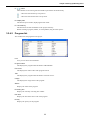
The dialog box has the following five tabs.
Robot info. tab
This displays project information.
Type
Displays the robot type.
54
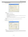
Chapter 4 Creating a Project
Communication setting tab
This specifies the communications link to the robot controller plus communications options.
Ethernet
Enter the robot controller's IP address.
• IP address
Enter the robot controller's IP address.
• Specify the IP address of the local machine.
If your PC has several network cards, you can specify the one to use when linking. Specify the network
card's IP address.
• Specify the port number of the local machine.
Check the box and enter the port number if you wish to specify the PC's port number when linking.
RS-232C
Input the RS-232C communications settings in line with those of the robot controller.
Compile tab
Sets data regarding the executable program.
File name
Specifies a file name when renaming the execution file. By default, a program project file name having the
extension "nic" is specified. If you do not wish to overwrite this file or wish to unify all the projects in an
executable file name, change this value.
55
Chapter 4 Creating a Project
Output code
Sets the software version of the robot controller. Depending upon the version, the output codes of the execution program will differ. If the version specified here is different from the actual software version of the
connected controller, an error will occur at the time of communication.
Language mode
Specifies the executable program language.
Explicit Type Declarations
Error will occur unless local variables are explicitly declared with a specification statement or postfix. If
this option is found invalid, without explicit descriptions, it will be regarded as a single accuracy variable.
Inspect Constant Range
Checks the range of an argument with the statement described as constant when creating the execution program.
Symbol table
Sets the size of working range for storing information on symbols.
Name table
Sets the size of working range for registering information on names such as label name. This range is used
to register information on all names handled by the program files included in the executable file.
Reallocation table
Sets the size of working range for determining the absolute addresses.
Block table
Sets the size of working range for storing the nested state of loops and conditional statement, etc.
Line table
Sets the size of working range for registering line information. The numerical value of this table is equal to
the number of all the lines that can be compiled. The same value is equal to the nest level allowed for compiling.
I/O table
Sets the size of working range for registering information on IO variables. The numerical value of this table
is equal to the number of defined IO variables.
Dim table
Sets the size of working range for registering information on array variables. The numerical value of this
table is equal to the number of array variables that can be defined.
Free chain
Sets the size of working range for registering information address link. This is the range used for solving
label addresses, jumping address of branch and loop commands, and global variables.
Name table
Sets the size of working range for registering information concerning label and other names. This is the
range used for registering information on reserved words and user-defined labels, etc.
56
Chapter 4 Creating a Project
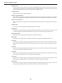
Variable tab
This specifies the number of variables used.
Set it to match the number of project variables used by the robot controller.
I/O tab
This specifies I/O assignments and I/O options.
For further details on I/O specifications / settings for each device, refer to the Option Equipment Manual.
57
Chapter 4 Creating a Project
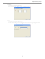
4.6
Configuring Parameters
Operating procedure
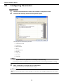
1.
2.
Choose Project|Parameters to display the parameter configuration sheets.
Click the tab containing the desired configuration option.
The dialog box has the following nine tabs.
• Communication tab
• Program tab
• Interpreter tab
• I/O tab
• DNet Master tab
• Path. tab
• Config. tab
• Servo tab
• Vision tab
Note
• Enabling the filter lists only parameters containing the specified string.
• Selecting the Mask unmodifiable items check box lists only those settings available for editing.
3.
When configuration is complete, press the OK button.
Pressing the Cancel button instead discards all changes.
Note
Moving to another tab does not save changes. To save your new settings, always press the OK button.
58
Chapter 4 Creating a Project
4.7
Link with Robot Controller
WINCAPS III supports two types of links for communicating with a robot controller:
• Ethernet connection
• Serial (RS-232C) connection
For further details, please refer to 1.5 "Connecting to Robot Controller" (P. 8) and the robot controller documentation.
4.7.1
Communications settings
After connecting the link, configure it at the WINCAPS III end.
For further details on configuring the robot controller, please refer to its Setting Guide.
Operating procedure
1.
2.
Choose Connect|Settings to open the Property dialog box to the Communications settings
tab.
Configure the link.
First specify the connection between the computer and the robot controller.
Ethernet connection
All that is needed is the robot controller's IP address.
For further details on determining this, please refer to the robot controller documentation.
Serial (RS-232C) connection
This link requires the following settings.
• Communications port
• Baud rate
• Parity bits
• Data length
• Stop bits
59
Chapter 4 Creating a Project
3.
Configure the options:
timeout and number of retries.
4.
4.7.2
Press the OK button to save the new settings.
Data transfers
This link is for exchanging data with the robot controller.
The following data is exchanged.
Program
Data concerning programs. There are two types of data for programs.
Source file
Uncompiled program data
Executable file / map file
Compiled program data
Variable
Data for all variable values.
Tool/Work/Area
Data on tools, work, areas.
Log
All log data. (receivable only)
Set log data in flash fields and so on using Log acquisition settings.
Parameter
All parameter data.
Includes parameters in the Parameter editing screen.
There are five types of data for parameters as follow.
Arm parameters
Parameter on movement of the robot.
• Path tab
• Config. tab
• Servo tab
I/O parameters
Parameters concerning I/O.
• I/O tab
• DNet master tab
Program parameters
Parameters concerning programs.
• Program tab
• Interpreter tab
Communication
Communications settings parameters (receivable only)
• Communication tab
60
Chapter 4 Creating a Project
Vision
Parameters concerning visual functions.
• Vision tab
Vision
All visual tools data.
Select Screen data settings on the Transfer data screen.
Configuration
All configuration data (calset values, etc.)
Note
Some items will not appear in the list of transferable data due to WINCAPS III settings or robot controller specifications.
Operating procedure
1.
Choose Connect|Transfer data... to display the bidirectional transfer dialog box.
2.
Select the data source(s).
Selecting the WINCAPS III check box sends data to the Controller; selecting the Controller one receives.
Note
Selecting multiple sources is perfectly acceptable.
61
Chapter 4 Creating a Project
3.
Press the Send or Receive button to display a confirmation dialog box.
4.
Press the Yes button to start transferring data and display a progress screen.
Note
Receiving data from the robot controller updates the WINCAPS III project data, nullifying any program
updates in the interim.
Caution
When transferring data to the robot controller, close the Program List window or the Select Variable
Type window (if opened) on the teach pendant beforehand; otherwise, the controller cannot load map
files or executable files transferred from WINCAPS III.
62
Chapter 4 Creating a Project
4.7.3
Arm parameter data transfer
The arm parameters contain a CALSET value deciding the robot's particular position data. CALSET values are
included when transferring arm parameters from the robot controller to WINCAPS III, but not vice versa in order
to prevent overwriting.
If you wish to transfer arm parameter data including CALSET values to the robot controller, refer to the Robot
Installation Protection Guide.
Arm parameters received from the controller can be written to a separate file or loaded as arm data.
Operating procedure
1.
2.
Log in at programmer level.
Choose Tool|Arm parameters to open the Arm parameter dialog box.
Save button
Writes WINCAPS III project arm parameters to a file.
Load button
Arm data from files below on your PC is uploaded to your current project.
• WAM: WINCAPS III arm data format
• WPJ: Loads only arm data from WINCAPS III projects.
• ARM: WINCAPS II arm data format
63
Chapter 4 Creating a Project
4.8
USB Tool
Instead of direct data transfer between a computer running WINCAPS III and the robot controller, a USB memory
is available as a media for data exchange between them.
4.8.1
Reading data from USB memory
Follow the FDTool wizard to read data from a USB memory.
Operating procedure
1.
Select Tool|USB|Read to start the FDTool wizard.
Read data from drive
This field specifies a drive for reading a USB memory.
New Project
This radio button is for creating a new project and reading data from a USB memory into the project.
Enter a project name and select a location for saving the project.
Merge with Existing Project
This radio button is for selecting an existing project and reading data from a USB memory into the
project. The data read from a USB memory merges with data in the existing project.
64
Chapter 4 Creating a Project
2.
Click the Next button.
Select a target folder
This area specifies folders in the USB memory to read data from them.
3.
Click the Next button.
Select target data
Selecting these check boxes specify data to read from the USB memory. To read all data, click the Select
All button.
65
Chapter 4 Creating a Project
4.
Click the Next button to read the specified data from the USB memory.
Upon completion of reading, the following dialog appears.
66
Chapter 4 Creating a Project
4.8.2
Writing data into USB memory
Follow the FDTool wizard to write data into a USB memory.
Operating procedure
1.
Select Tool|USB|Write to start the FDTool wizard.
Write data into drive
This field specifies a drive for writing into a USB memory.
ROBOTPRJ (Root)
This radio button is for writing the entire project file into a USB memory.
Following folder
This radio button is for specifying a folder in the project and writing data held in the folder into a USB
memory.
Note
When writing data into a USB memory, first open a target project and then start the FDTool wizard.
The wizard cannot select an unopened project.
67
Chapter 4 Creating a Project
2.
Click the Next button.
Select target data
Selecting these check boxes specify data to write into the USB memory. To write all data, click the Select All button.
3.
Click the Next button to write the specified data into the USB memory.
Upon completion of writing, the following dialog appears.
68
Chapter 4 Creating a Project
4.9
Print
Project data of various types can be printed out.
Operating procedure
1.
Choose File|Print to display the Print dialog box.
2.
Select the data you wish to print and press the Preview button.
Check the preview and then make your print out.
Note
Printing out log data can result in vast amounts of printout pages, hence be sure to check the number
of pages using the preview function first before printing.
69
Chapter 5 Writing Programs
5.1
Creating a New Program
Operating procedure
1.
2.
Choose Project|Add Program... to display the dialog box for creating a new program, header file, or teach pendant (TP) panel.
Specify the type.
There are three choices.
• Program (*.pac)
• Header (*.h)
• Panel designer (*.pnl)
The box to the right automatically displays the corresponding template.
3.
Specify a name (title) for the program.
The default is to use this program name as the file name.
To use a different file name, enter it in the File name field.
4.
Press the OK button to open a new file based on the template in the corresponding window: a Program edit window in the Program view area for a program or header file or the
Panel Designer window for a TP panel.
Panel Designer procedures appear in the Panel Designer User's Manual separately issued.
Note
• The folder for the new file is the default (shown in gray) currently selected in the Project window.
If the target folder already contains a file with the name specified, pressing the OK button displays
an error message and returns to the dialog box.
• The limit is one TP panel per folder.
70
Chapter 5 Writing Programs
5.2
Leveraging Existing Files
In practice, a key technique is to recycle files from other projects.
There are three file types.
• Program file (*.pac)
• Header file (*.h)
• Teach pendant panel (*.pnl)
Operating procedure
1.
2.
Choose Project|Import... to display an Open dialog box.
Select the file to add and press the Open button to add it to the Project and Program list
windows.
Note
• The folder for the file is the one currently selected in the Project window. If that folder already contains a file with that name, however, a dialog box asks permission to overwrite it.
• If you wish to import by folders, choose Project|Folder|Import and specify the folder.
71
Chapter 5 Writing Programs
5.3
Saving a Program
The following procedure saves edits to the current program.
The File menu offers two ways to save modifications to the file in the selected Program edit window.
• Save updates the original file.
• Save As... saves them under a different name.
Only the latter warrants detailed description.
Operating procedure
1.
2.
Choose File|Save As... to display a Save As dialog box.
Specify the target folder and file name and press the Save button to save the contents of
the Program edit window there.
If that folder already contains a file with that name, however, a dialog box asks permission to overwrite it.
Note
• If there are multiple programs in the Program view area, the file saved is the active one, the one
in the currently selected Program edit window.
The File menu emphasizes this by adding the file name to the two menu items.
• If that folder already contains a file with that name, however, a dialog box asks permission to overwrite it.
72
Chapter 5 Writing Programs
5.4
Editing a Program
Double-clicking a program or header file in the Project or Program list window opens it for editing in a Program
edit window.
Note
• If the Project window does not show file names, press its Display files button.
• The Program view area provides a tab interface for switching between files.
Alternatively, tiled and other layouts display multiple files for direct selection.
WINCAPS III provides the following program editing functions.
Configurable Program edit windows
The Program edit window text editor gives the user control over the font, size, and colors for displaying text.
Syntax highlighting assigns different colors to distinguish between, for example, operators and comments. For
further details on Program edit window display options, refer to 3.1.1 "WINCAPS III basic settings" (P. 14).
Finding and replacing strings
Find and replace strings in headers and programs.
Search ranges and regular expressions can be used.
Other functions
• Jump to...
This is for moving the cursor to a line, specified by number, in the Program edit window.
• Comment out
This submenu command changes the lines selected in the Program edit window into comments.
• Indent
This submenu command indents the lines selected in the Program edit window.
• Bookmark
This submenu is for working with bookmarks, markers on lines in Program edit windows.
These markers make it easier to return to that position.
• Helper functions
These are to help command input by listing candidates and showing command syntax.
73
Chapter 5 Writing Programs
5.4.1
Finding and replacing strings
You can specify the range and method to search and replace the character string.
Target items
This field specifies the range of the target to be searched/replaced.
Choose Project to specify the file type.
Option
You can specify various search methods.
You can also select the files when executing Replace all.
Note
Double-clicking a line in the Search results window displays the corresponding program line.
74
Chapter 5 Writing Programs
5.4.2
Other editing functions
5.4.2.1 Jump to...
This is for moving the cursor to a line, specified by number, in the Program edit window.
Operating procedure
1.
2.
3.
Choose Edit|Jump to... to display the eponymous dialog box.
Enter the line number.
Press the OK button to move the cursor to that line.
5.4.2.2 Comment out
This submenu command changes the lines selected in the Program edit window into comments.
Operating procedure
1.
2.
Select the lines to comment out.
Choose Edit|Comment Block|Comment to convert them to comments.
Note
To reverse this operation, select lines and choose Edit|Comment Block|Decomment.
75
Chapter 5 Writing Programs
5.4.2.3 Indent
This submenu command indents the lines selected in the Program edit window into comments.
Operating procedure
1.
2.
Select the lines to indent.
Choose Edit|Indent|Indent to indent them.
Note
To reverse this operation, select lines and choose Edit|Indent|Unindent.
5.4.2.4 Bookmark
This submenu command is for setting a bookmark on the line under the cursor, or moving the cursor to a bookmark.
(1)
Setting a bookmark
The following is the procedure for setting a bookmark on the line under the cursor.
Operating procedure
1.
2.
Move the cursor to the line on which to set the bookmark.
Choose Edit|Toggle Bookmark to set the bookmark or, if there is already a bookmark there,
delete it.
Bookmark
(2)
Moving to a bookmark
There are submenu commands for moving the cursor to a line with a bookmark.
Operating procedure
1.
Choose Edit|Bookmark|Next Bookmark to move the cursor downward from the current position to the next bookmark.
To move the cursor upward, choose Edit|Bookmark|Previous Bookmark instead.
76
Chapter 5 Writing Programs
(3)
Clearing bookmarks
There is a menu command for clearing all bookmarks.
Operating procedure
1.
Choose Edit|Bookmark|Clear Bookmarks.
5.4.2.5 Command candidate function
As you type a command, a command list will appear. (Ctrl + Space key will also display the command list)
The command list will automatically scrolls to the first match.
Typing CA, for example, highlights CALL.
Selecting a command on this list displays a functional description to the right.
Double-clicking one inserts it in the text.
77
Chapter 5 Writing Programs
5.4.2.6 Insert command function
The Insert command submenu lists commands by function.
Selecting a command on this list inserts it into the program being edited.
Operating procedure
1.
2.
Move the cursor to the insertion position.
Choose Edit|Command Input to list the commands by function.
Note
Choosing a command inserts it with default values for any command parameters.
Edit these values without worrying about parameter syntax.
78
Chapter 5 Writing Programs
5.4.2.7 Command builder function
This is for command input through Command builder at the cursor point in the program being edited. Necessary
parameters can also be input, allowing correct parameter statements.
You can also select from command searches or past commands entered. Help can be referred to for the commands
shown, enabling quick command input.
Programs created by users in the project are also displayed, call programs can also be created.
A
B
C D
F
E
G
H
A: History
Select command from history of previously entered commands.
B: Find
Search commands using their names or description.
C: Insert
Selected commands are input at the cursor position on the program editing window.
D: Help
This displays the Help for the selected command.
E: Command list
Commands are listed by category.
P: Parameter
List of parameters for the selected command. Correct commands can be created by input into the values columns.
G: Brief description
Shows a simple description of the command.
H: Input command display
Displays the text inserted for the command, including the input parameters.
79
Chapter 5 Writing Programs
5.4.2.8 Insert registered character string
Allows registration of character strings commonly used in program editing for fast insertion.
(1)
Register character string
Operating procedure
1.
2.
3.
(2)
Press the desired key to which the selected string should be assigned.
Choose Edit|Register string.
Press the desired key to which the selected string should be assigned.
Insert registered character string
Operating procedure
1.
2.
3.
In the Program edit window, move the cursor to the line to which the registered string
should be inserted.
Choose Edit|Insert registered string.
Press the key to insert the character string into the program edit window.
80
Chapter 5 Writing Programs
5.4.2.9 Add comment function
Automatically adds comments to explain the applications of the variables and I/O during program editing.
Comments are added with "'//" placed after them.
If a further comment is added after changing the application description of the I/O and variables, the content from
"'//" onwards is updated.
81
Chapter 5 Writing Programs
5.5
Program Bank
The program bank allows robot applications to share library programs/functions originally written for one specific
robot or application.
Note
Program samples are already preset in the program bank. For further details on program samples,
please refer to Programming Manual II.
5.5.1
Adding a program to a project
This adds a program from the program bank to a project.
Operating procedure
1.
Choose Project|Program Bank to display the eponymous dialog box.
These programs are listed by category. Double-clicking a category displays the programs in that category.
2.
Select a program.
Two tabs switch between the documentation and source code for the selected program.
Readme tab
Proper documentation covers function, syntax, usage, conditions, limitations, and other particulars.
Source tab
This displays the source code for the selected program.
82
Chapter 5 Writing Programs
3.
5.5.2
Press the Add program button to add the program to the folder selected in the Project window. Other programs within the project can then access this program with CALL statements.
Adding a program to the program bank
The following procedure adds a user program to the bank register.
Operating procedure
1.
2.
Choose Project|Program Bank to display the dialog box.
Select the category.
The first dozen categories, with names starting with exclamation points (!DW00 to !DW11: Miscellaneous)
are locked, so choose another category.
To add a new category, refer to 5.5.3 "Adding a category" (P. 84).
3.
Press the Add program button to display the Add title dialog box.
83
Chapter 5 Writing Programs
4.
Enter a title for the program and press the OK button.
5.
Fill out the two tabs.
For the Source tab, copying the contents of the corresponding Program edit window is much faster than retyping the program.
6.
Press the Update button.
This registers it in the program bank.
5.5.3
Adding a category
Operating procedure
1.
2.
3.
Select the root category, Bank.
Press the Add category button to display the eponymous dialog box.
Enter a name for the category and press the OK button.
84
Chapter 5 Writing Programs
5.6
Editing a Teach Pendant (TP) Panel
A TP panel represents the interactive image displayed on the screen of the teach pendant attached to the robot controller.
5.6.1
Editing a TP panel
To edit a TP panel (*.pnl), double-click it in the Project or Program list window to open it in the Panel Designer
window.
Note
• If the Project window does not show file names, press its Display files button.
• Panel Designer procedures appear in the Panel Designer User's Manual separately issued.
85
Chapter 5 Writing Programs
5.7
Folder Functions
Folders hold the key to hierarchical management of the program files in a project.
Grouping program files into folders by function or type adds structure that makes overall operation easier to understand and encourages compartmentalization, enhancing program portability to other projects.
5.7.1
Creating a folder
Operating procedure
1.
Select the parent, the folder in the Project window to hold the new folder.
2.
Choose Project|Folder|New to create a new folder and select its name for editing.
3.
Enter a name for the folder.
Note
This folder name can be modified at a later date.
86
Chapter 5 Writing Programs
5.7.2
Importing an entire folder
Importing a folder is much faster than importing the files one at a time.
Operating procedure
1.
2.
3.
Select a folder in the Project window.
Choose Project|Folder|Import to display the Browse folders dialog box and specify the
folder to import.
Press the OK button to copy the selected folder as well as the files inside to the target folder selected in the Project window.
Note
If the target folder already contains a file with the same name, however, a dialog box asks permission
to overwrite it.
87
Chapter 5 Writing Programs
5.8
Making Executables
5.8.1
Checking syntax
The following procedure runs a syntax check on the selected program.
Note
The target is the file in the currently active Program edit window.
Operating procedure
1.
2.
Select the program to check.
Choose Project|Check Syntax to run the check and display the results in an Output window.
A syntax error triggers an error message consisting of an indication,
note in the Output window.
, the line number, and a brief
Double-clicking on this message highlights the corresponding line in reverse in a Program edit window.
Note
There is an option for automatically running this check on the program after each save.
Choose Project|Properties to display the project property sheets and look for it on the Compiler tab.
88
Chapter 5 Writing Programs
5.8.2
Making executables
This batch operation applies to all files in the project.
Note
The update is conducted for all programs registered in the project.
Operating procedure
1.
Choose Project|Compile to update the executables for the project.
An Output window in the Docking View window tracks progress and error messages from the compiler.
An error triggers an error message consisting of an indication,
in the Output window.
, the line number, and a brief note
Double-clicking on this message highlights the corresponding line in reverse in a Program edit window.
Note
• Checking executable operation requires first downloading it to the robot controller with the procedures in 4.7.2 "Data transfers" (P. 60).
• To specify file names for executables, choose Project|Properties to display the project property
dialog box and select the Compiler tab.
89
Chapter 5 Writing Programs
5.9
Simulation function
Cycle time, trajectory, posture, and so on can be checked by running a created program on the PC. In addition, the
program can be debugged because variables can be monitored during execution and edited.
5.9.1
Grammar check of simulation function
Grammar check of the selected program is performed when entering the simulation mode. Grammar check to run
the program with the normal robot controller is performed first, then a grammar check to see if the program can be
run with the simulation function is performed. Commands that can be run with the robot controller but cannot be
run with the simulation function are enclosed with "#IFDEF...#ENDIF". Commands enclosed by "#IFDEF...#ENDIF" are not run with the simulation function, but they are run with the robot controller, thus they can be sent to
the robot controller and used as is.
Select [Edit]-[Delete codes for simulation] to delete the codes ("#IFDEF...", "#ENDIF") added by the grammar
check of the simulation function.
Normal
5.9.2
Simulation mode
Simulation function and global variables
When values of variables, work pieces, tools and areas are modified by the program started in the simulation mode,
you can select whether to revert to the values before execution or to save the modified values.
Also, global variables can be edited even while running simulation.
5.9.3
Precautions for simulation function
• Multiple programs cannot be started. “call” and “run” are not supported.
• Simulation function supports part of the commands for calculating cycle time or checking trajectory and operation posture, etc.
• Users must not input "#IFDEF ... #ENDIF" by themselves.
• Programs with arguments are not supported.
• Arm semaphore (axis control right) is not checked. Control rights of all valid axes are automatically obtained.
90
Chapter 5 Writing Programs
5.9.4
List of supported commands
Robot control statement
Move, Approach, Depart, Draw, Drive, DriveA, Speed, Accel, Decel, ChangeTool, ChangeWork, Wait, Delay
Multitasking control statement
TakeArm, GiveArm
Flow control statement
For-Next, Do-loop, If-Then-End If, Select Case-End Select
Input output control statement
Set, Reset
Others
Four arithmetic operations, Arithmetic Function, Trigonometric functions, Coordinate conversion,
Character string operations
Note
• Free curve function of "MOVE" command (MOVE S) is not supported.
• Simulation function does not check arm semaphore (axis control right).
• Simulation function interprets "true" as "-1". When using "Set" and "Reset" commands, write programs using "ON"/"OFF".
• Vector operation is not supported.
91
Chapter 6 Arm 3D View Window
The Arm 3D view window displays, in three dimensions, the robot's current position and attitude.
Simulation allows the efficient and safe development of robot control programs without having to connect an actual robot.
During remote debugging, the robot arm on the screen responds to program commands.
6.1
Screen Descriptions
6.1.1
Arm 3D view
This window displays, in three dimensions, the robot's current position and attitude.
It is for visualizing robot activity, determining the robot's operation range, and, after adding other objects to the
layout, detecting collisions with surrounding equipment.
A
B
C
D
A: Current positions
This area displays the current values of robot position variables of types P, J, T, and J-EX.
The Arm|Display current angles submenu switches the layout here.
B: Work number
This area displays the current work number.
The Arm|Work coordinate monitor submenu switches between display/non-display of the layout here.
C: Tool number
This area displays the current tool number.
The Arm|Tool coordinate monitor submenu switches between display/non-display of the layout here.
92
Chapter 6 Arm 3D View Window
D: Arm 3D view tool bar
D-1
D-2
D-3
D-4
D-5
D-6
D-7
D-8
D-1: Rotate
This rotates the view on the screen using a mouse.
D-2: Fixed view
This fixes the current view on the current position.
D-3: Rotation on Z-axis
This rotates the view on Z-axis using a mouse. (Default)
D-4: Rotate: screen bisection
This rotates the view on the horizontal/vertical axis.
D-5: 3D view teach
This teaches by clicking the object.
D-9
D-6: Measure point-to-point distance
This measures the distance between two clicked points.
D-10
D-7: Screen shot
This captures the current screen image and saves it as a file.
D-11
D-12
D-13
D-14
D-15
D-16
D-17
D-18
D-19
D-20
D-8: Recording setting
This performs video compression settings for recording.
D-9: Recording start and stop
This starts and stops recording.
D-10: 3D screen
This switches the screen to the 3D (perspective projection) mode.
D-11: 2D screen
This switches the screen to the 2D (parallel projection) mode.
D-12: Move origin
This moves the origin of the base coordinates to the center of the screen.
D-13: Whole object
This resizes the display to show the whole object.
D-14: Change view (+X)
This shows the display viewed from the +X direction.
D-15: Change view (+Y)
This shows the display viewed from the +Y direction.
D-16: Change view (+Z)
This shows the display viewed from the +Z direction.
D-17: Change view (-X)
This shows the display viewed from the -X direction.
D-18: Change view (-Y)
This shows the display viewed from the -Y direction.
D-19: Change view (-Z)
This shows the display viewed from the -Z direction.
D-20: Help
This shows the operating procedure in the right corner of the screen.
93
Chapter 6 Arm 3D View Window
Moused-based viewing operations
• Rotate: Left button + drag
• Pan: Left / right button hold + drag
• Zoom: Right button + drag
Moused-based robot / object operations
• Select: Left-click
• Move object view to the center of the screen: Shift + left-click
• Object full screen display: Alt + left-click
• Move: Ctrl + Left-click
• Move in a straight line: Coordinate axis Left button + drag
• Rotate: Ctrl + coordinate axis Left button + drag
94
Chapter 6 Arm 3D View Window
6.1.2
Arm modeling
This window is for adding tools, work pieces, obstacles, and other objects to the equipment layout in the Arm 3D
view window using 3D data from either the built-in simple modeling software or external sources.
A
C
B
D
E
G
J
F
I
H
K
A: Object tree
This shows the object hierarchy behind the Arm 3D view.
Right-clicking anywhere in the object tree area displays the following context menu.
Add node
This is for adding a node underneath the selected object.
Add 3D data
This is for adding an object using 3D data from an external source.
Import shape data
This is for reading in existing modeling data.
Export shape data
This is for saving the modeling data for the selected node or object as a file.
Cut
This moves the selected object to the Windows clipboard.
Copy
This copies the selected object to the Windows clipboard.
Paste
This inserts the object in the Windows clipboard as a child of the currently
selected object.
Delete
This deletes the selected nodes and objects.
Change name
This is for changing the name of the selected node or object.
Move Robot Data
This is for moving all data of Base objects including the robot on the object
tree.
The robot data moves as a child of the selected node or object.
95
Chapter 6 Arm 3D View Window
Children nodes...
All objects below the selected node can be expanded/collapsed, displayed /
not displayed, interference checked / not checked.
Property
This displays the property sheets for the selected object.
B: Add buttons
These add an object of the shape indicated on the button. There are six shapes available.
C: Node button
This adds a node.
D: External button
This reads in 3D data from an external source.
E: Name
This field specifies a name for the selected object.
F: Color
This field specifies a color for the currently selected object.
G: Display check box
Selecting this check box displays the currently selected object in the Arm 3D view.
H: Collision detection check box
Selecting this enables collision detection for the currently selected object.
I: Properties button
This displays the property sheets for the currently selected object.
J: Relative position
These fields specify the relative position for the currently selected object.
X, Y, Z
: Relative x/y/z coordinates in mm.
RX, RY, RZ
: Angles relative to the corresponding axis, in degrees.
K: Size
These fields specify the dimensions for the object selected on the tree.
X, Y, Z
: Dimensions along the x-, y-, and z-axes, in mm.
The radio buttons above offer a choice of specifying half- or full-sized measurements.
Note
• If the data of the selected object is 3D data imported, the Size fields specify the magnification.
Assuming the original size of the 3D data as "1," specify the magnification.
• Imported 3D objects cannot be edited.
• Entering negative values into the Size fields inverts the object.
96
Chapter 6 Arm 3D View Window
6.1.3
Arm operation
This window is for moving the simulated robot in the Arm 3D view window.
A
B
C
D
E
F
A: Ope. mode
Select movement mode.
• Axes: operates all axes.
• XY-bisection: moves according to the selected work coordinates. RX/RY/RZ rotate around the work coordinates centered on the tool origin point.
• Tool: moves according to the selected tool coordinates. RX/RY/RZ rotate around the work coordinates
centered on the tool origin point.
B: Work coordinates
Select work coordinates.
C: Tool coordinates
Select tool coordinates.
D: Speed/Inching
Select normal running or inching.
• Speed: While the "Move position" button is held down, the corresponding robot joint continuously moves
at the specified speed (%).
• Inching: Each time the "Move position" button is pressed, the corresponding robot joint inches by the specified amount of movement (mm or degree).
E: Move position buttons
Moves the robot displayed in Arm 3D view in accordance with the selected movement mode.
F: 3D view teach
Teaches the posture symmetry to the surface when clicking an object within the Arm 3D view window.
97
Chapter 6 Arm 3D View Window
6.2
Simple Modeling
The built-in tool is for quick and dirty modeling of the pallet bench, pallet, work, and other objects.
The Model tree window presents a hierarchical display of the objects in the Arm 3D view.
The top node is Root, which starts out with the following predefined nodes.
Nodes are virtual items to combine multiple objects and name them.
Work group
This group contains the coordinates for eight work pieces, Work0 to Work7.
Selecting the Display check box in the Model tree window displays the current coordinates in the Arm 3D view
window.
The work group node relative positions reflect the Work coordinate settings. Choose View|Tool/Work/Area
Settings|Work to display this window for modifying these settings. (Work0 cannot be edited on the base center.)
Tool group
This group contains the coordinates for sixty four tools, Tool0 to Tool63.
Selecting the Display check box in the Model tree window displays the current coordinates in the Arm 3D view
window.
The tool group node relative positions reflect the Tool coordinate settings. (Tool0 cannot be edited on the base
center.)
Area group
This group contains the coordinates for 32 areas, Area0 to Area31.
Selecting the Display check box in the Model tree window displays the current coordinates in the Arm 3D view
window.
98
Chapter 6 Arm 3D View Window
Adding nodes
A node may be added anywhere in the object hierarchy.
Select a node on the object tree, right-click, and choose Add node from the context menu that appears to add a
new node as a child of the selected one.
Note
Grouping the pallet, pallet bench, and other objects under a common node, for example, enables
copying and pasting them together as a single group.
6.2.1
Adding objects
The following is the procedure for adding the pallet bench, pallet, work pieces, and other objects to the Arm 3D
view window.
Layout example
99
Chapter 6 Arm 3D View Window
As our example, let's start with the pallet bench.
Operating procedure
1.
2.
3.
4.
Choose View|Arm View to display the modeling window.
Specify where to add to the model by selecting a node to be the parent.
Press the
(Box) button in the Model tree window to add a box to the Arm view window.
Modify the object to give it a name and a color.
Change name
Right-click on the object and choose Change name from the context menu that appears to highlight the
name, ready for editing.
Changing color
To change the color of an object, press the Pick color button in the Model tree window and choose from
the palette that appears.
100
Chapter 6 Arm 3D View Window
5.
Change the object's position and size.
6.
Add two more boxes to complete the pallet bench.
Note
Here, it is faster to copy and paste the above box as the second leg and then again as the starting
point for the top.
101
Chapter 6 Arm 3D View Window
Note
The way the object is displayed can be altered with the Model tree Property button.
Pressing the Property button displays the dialog box below.
Display setting
Sets object display properties.
Related axis
Settings for objects moving in relation to the added axes in the case of projects with added axes
or SMT7 controller. Set the axis, movement and movement units.
Collision detection setting
Detection level: Specifies the sensitivity for detection of collisions.
Display detection area: Displays the range for detecting object collisions.
Detailed option: Further options for the range for detecting collisions with imported 3D data.
102
Chapter 6 Arm 3D View Window
6.2.2
Saving objects
Saving objects as modeling data files allows immediate reuse in other projects.
Operating procedure
1.
2.
3.
Select the object or node to export.
Right-click and choose Export data from the context menu that appears to display the
Browse folders dialog box.
Select the target folder and press the OK button.
Note
All objects contained in the selected nodes / objects are also saved.
103
Chapter 6 Arm 3D View Window
6.2.3
Importing objects
The following is the procedure for reading in modeling data exported from another project.
Operating procedure
1.
2.
3.
Select the parent node for the data.
Right-click on the object tree and choose Read shape data from the context menu that appears to display the dialog box for selecting a file to import.
Select a file and press the OK button.
Selection is limited to shape files (*.pt3).
104
Chapter 6 Arm 3D View Window
6.3
Importing 3D Data
The following is the procedure for adding an object using 3D data from an external source.
The following formats are supported.
• Directx file (*.x)
• VRML 2.0 file (*.wrl)
Note
WINCAPS III does not support the VRML 1.0 format.
Use VRML 2.0 (or VRML 97) format data.
Operating procedure
1.
2.
Select the parent node for adding the object.
Right-click and choose Import modeling data from the context menu that appears to display the dialog box for importing such data.
105
Chapter 6 Arm 3D View Window
3.
Select a file and press the OK button.
The default format is DirectX. For VRML data, switch the file type to VRML (*.wrl).
The corresponding object appears in the Arm 3D view.
Note
The units of the data scale may differ according to the software on which the 3D data was created.
Select the appropriate unit and import.
Imported 3D data may display a mirror image. Enter a negative value in the Scale box to display a
normal image.
106
Chapter 7 Online Functions
7.1
Overview
These functions are for monitoring robot controller variables, I/O, and other aspects of operation and for checking
robot controller program operation under WINCAPS III control.
They cover all phases of robot application development.
Preliminary investigation with no actual equipment
• Equipment layout with 3D modeling
• Collision detection using this 3D model
• Dummy I/O input
Adjusting initial equipment setup
• Modifying variables and I/O
• Running programs
Troubleshooting equipment already in production use
• Monitoring variables and I/O
• Displaying error, operation, variable, I/O, and trace logs
7.1.1
Monitoring and debugging
The online functions serve two basic purposes.
Monitoring
This monitors the status of the robot controller.
Displays the robot's attitude in the Arm 3D view, and the variables, I/O, program executable lines. All types of
variables can be edited.
This software can receive all log data and preserve them.
Debugging
In addition to monitor functions, programs in the robot controller can be executed on your PC for debugging.
Caution
Debugging is not possible for robot controllers prior to Version 2.7.
The software also debugs programs, using the following functions.
• Adjust robot speeds
• Reset all programs
• Start/stop supervisory tasks
• Run programs
• Choice of Step-stop, Cycle-stop, Halt, and Program Reset
• Step in
• Toggle breakpoint
• Clear all breakpoints
• Breakpoint stop setting
• Dummy I/O for system inputs
107
Chapter 7 Online Functions
7.2
Monitoring
For further details on connecting to a robot controller, refer to 1.5 "Connecting to Robot Controller" (P. 8) and 4.7
"Link with Robot Controller" (P. 59).
7.2.1
Initiating monitoring
Operating procedure
1.
Choose Connect|Monitor Communication|Monitoring (online) to initiate monitoring.
Note
This menu command is only available when the robot controller is offline. It is not available during debugging (online).
2.
Wait for monitoring to start.
A status bar appears to display the current monitoring status.
Note
When connection for online operation is complete, WINCAPS III windows automatically display robot
controller internal data. Returning online brings you back to the project in the PC. (The received log
data also remains in the PC project.)
108
Chapter 7 Online Functions
7.2.2
Monitoring variables
There are three window types for monitoring variables.
7.2.2.1 Adding variables to the watch list
There are two ways to monitor variable's contents: directly selecting it to temporarily display its value as pop-up
tip text and adding it to the Watch list.
Operating procedure
1.
Double-click a program in the Project or Program list window to display that file in the Program view area.
A
B
A: Current step (line)
Highlighting indicates the current program line.
B: Variable contents
The contents of the currently selected variable appear as pop-up tip text.
2.
Select a variable and choose Debug|Show Quick Watch to display this dialog box.
3.
Press the Register button to add the selected variable to the Watch list.
For further details on Watch window settings, refer to 7.2.2 "Monitoring variables" (P. 109).
109
Chapter 7 Online Functions
7.2.2.2 Confirm the registered watch items.
This window displays variables from a user configurable list.
Operating procedure
1.
Choose View|Watch to display this window in the Docking view area.
Task
This displays the program name.
Variable name
This displays the registered variable names.
Value
This displays the variable values.
Type
This displays the variable types.
Log
Select Valid / invalid for the log.
Select Valid if a log is to apply.
7.2.2.3 Checking global variables
This window type displays global variables of types I, F, D, V, P, J, T, and S.
Operating procedure
1.
Choose View|Variables and choose a type from the submenu to add the corresponding
window in the Docking view area.
Jump
Displays the specified number.
Smart View
Displays only variables with a check in the Smart column.
110
Chapter 7 Online Functions
No.
Displays the variable numbers.
Value
Displays the value.
Application
The user can enter the application. When the Add comment function is in use, text input for the Application is added to the program as a comment.
Macro name
Enter the name of macros usable in the project.
Smart check box
Only those variables checked will be displayed.
7.2.2.4 Checking local variables
This window type displays local variables for the currently selected program.
Operating procedure
1.
Choose View|Local Variables to display this window in the Docking view area.
Variable name
Displays the variable names.
Value
Displays the value.
Type
This displays the variable types.
111
Chapter 7 Online Functions
7.2.3
Monitoring I/O
The I/O window shows the current I/O states.
Operating procedure
1.
Choose View|I/O Window to display this window in the Docking view area.
Jump
Displays the I/O of the specified number.
Smart View
Displays only I/O with a check in the Smart column.
Oscilloscope display button
Turns on/off the Oscilloscope display.
Dummy input button
Dummy input is possible for I/O with a check in the Dummy column.
Hide unused field button
Pressing this button hides unused fields, fields to which no I/Os are assigned as shown with "--" in the
Type column.
No.
I/O port number.
State
A green icon is displayed when on and gray when off. You can switch between on/off by clicking on the
icon when in Dummy input mode.
Type
Displays the I/O type. Displays I/O port type: input/output, exclusive/universal, internal/hand I/O, etc.
Application
Users can add comments for each I/O port. Already input in exclusive signals, etc.
Macro name
Input the macro handling the I/O as the name inside the program. This is already input but can be freely
changed.
Dummy
Dummy operations are possible for I/O with a check in this column.
Log
I/O with a check in this column will have a log record. The upper limit is 50 at a time.
112
Chapter 7 Online Functions
Smart
Press the Smart view button to display only I/O with a check.
Oscilloscope
Displays whether the I/O is on/off in oscilloscope fashion. On/off changes can be checked with a timeline.
7.2.4
Monitoring robot
The Arm 3D View window shows the robot's current attitude.
The trajectory of the robot's hand movements can be displayed.
This trajectory display can be operated by choosing Arm|Movement history.
7.2.5
Errors during monitoring
A robot controller error displays a WINCAPS III error message.
113
Chapter 7 Online Functions
7.2.6
Validate the controller function extension
This enables validation/invalidation of controller function extensions from WINCAPS III.
Select Tool|Controller function extension in online (monitor) mode to open the Controller function extension dialog box.
Enter the password number for the function to be extended and press on the Add button to validate it.
To invalidate them, enter the validation password number and press the Delete button.
114
Chapter 7 Online Functions
7.3
Using Debugging
Robot controller version 2.7 or later
For further details on connecting to a robot controller, refer to 1.5 "Connecting to Robot Controller" (P. 8) and 4.7
"Link with Robot Controller" (P. 59).
7.3.1
Initiating debugging
First the robot controller must satisfy the following conditions.
• The mode selector switch (physical switch) on the teach pendant or mini-pendant must be in its AUTO position.
• The communications link must be properly configured.
Link type
For Serial (RS-232C) (COM2) : This must allow read/write access.
Ethernet
: The individual address list must allow read/write access from the computer.
Only computers with Read/write in the column circled in red can initiate debugging.
For further details on configuring the robot controller, please refer to its Setting Guide.
• No PAC programs are running.
• All motors are OFF.
115
Chapter 7 Online Functions
Caution
• The WINCAPS III debugging functions are for running robot programs and controlling operation
from the computer.
To ensure safety, always stay within reach of an Emergency stop button on the teach pendant,
the mini-pendant, or the equipment.
• Never debug over a link that puts the equipment out of sight of the operator at the computer.
Operating procedure
1.
Choose Tool|Option and select the Enable online-debug mode check box on the General
tab.
Note
• Leaving Enable online-debug mode deselected disables all debugging functions, so selecting
one during online operation triggers an error message.
• WINCAPS III always starts with debugging disabled.
2.
Choose Connect|Debugging (online) to initiate debugging.
A status bar appears to display the current debugging status.
A Stop button also appears independent of WINCAPS III.
Status bar
116
Chapter 7 Online Functions
Stop button
The teach pendant or mini-pendant also display a Debugging status screen.
Automatic aborting of debugging
WINCAPS III and the robot controller automatically switch to offline operation if any of the following
situations arises.
• Someone switches the pendant's mode selector switch away from its AUTO position.
• They detect severance of the link between them.
• They detect severance of the robot controller's link with the teach pendant or mini-pendant.
• The robot controller loses power.
• A password-protected screen saver kicks in.
Side effects
Switching to offline operation triggers the following cleanup operations.
• Stopping PAC programs
• Turning off motors
• Stopping supervisory tasks
• Closing teach pendant (TP) panels
• Clearing all breakpoints
• Clearing all dummy I/O settings
Note
When connection for online operation is complete, WINCAPS III windows automatically display robot
controller internal data.
Caution
Debugging imposes the following restrictions.
• Only the computer doing the debugging can run PAC programs (or supervisory tasks) or turn on
motors, not a teach pendant, a mini-pendant, I/O devices, or other computers running the ORiN
SDK.
• The teach pendant cannot load programs.
117
Chapter 7 Online Functions
7.3.2
Launch the program from WINCAPS III.
In addition to monitoring, WINCAPS III runs and debugs programs stored inside the robot controller.
Operating procedure
1.
Double-click the program to execute in the Project or Program list window to display it in
the Program view area.
2.
Choose Debug|Start a Task to display a confirmation dialog box.
3.
Select an option and press the OK button to run the robot program as specified.
The robot will operate following the program's commands.
The Arm 3D view, if open, tracks actual robot operation.
Note
When debugging supervisory tasks from WINCAPS III, the following functions are used.
• Step in, Step-stop
• Halt
• Program reset
• Toggle breakpoint
Note that stop commands to all programs, such as Emergency stop and Reset all programs, cannot
stop supervisory tasks.
118
Chapter 7 Online Functions
Caution
The WINCAPS III buttons are useless if the computer crashes or the communications link is lost. To
ensure safety, always stay within reach of an Emergency stop button on the teach pendant, the minipendant, or the equipment.
7.3.3
Controller settings
Debugging allows WINCAPS III to modify the robot controller's operating settings.
The following settings are accessible.
• Motor
These control power to the corresponding motor.
• Machine lock
The ON setting locks the robot, limiting WINCAPS III control to the simulation.
• I/O lock settings
These duplicate the teach pendant settings under F4 (I/O), F6 (auxiliary functions), and F7 (I/O Lock).
• External speed settings
These modify the Speed, Acceleration, and Deceleration speed settings.
• Automatic mode settings (Standard robot controller specifications only)
The choices are external and internal.
119
Chapter 7 Online Functions
7.3.4
Input signal dummy operation
Operation of the program can be checked even without peripheral devices linked by dummy alteration of the I/O
input signal.
7.3.4.1 Configuring dummy I/O
Dummy operation of the I/O requires selection of the input signal to be operated.
Operating procedure
1.
Choose View|I/O Window to display this window in the Docking view area.
2.
Switch on the Dummy check box for the dummy operation input signal.
120
Chapter 7 Online Functions
If several input signals are set, specify the range by dragging and combine them by selecting Enter dummy
check or Remove Dummy check using the mouse right-button menu.
3.
Press the Dummy input button to reflect the dummy I/O settings in the robot controller.
Press the Dummy input button again to remove the robot controller dummy I/O settings.
Note
• If communications errors occur using DeviceNet or other field networks, dummy input settings
cannot be made unless field network display error settings are 1:Default. Refer to Field Network
Display Error Parameters in the RC7M Controller Manual Option Equipment Manual regarding
such display errors.
• Dummy I/O settings are not possible for applications listed as Reserved for exclusive input.
Switch the Dummy check boxes off before using.
121
Chapter 7 Online Functions
7.3.4.2 Input signal on/off operation
Press the Status lamp of the input signal to be turned on/off. When lit green it is on, when gray it is off.
7.3.4.3 Exclusive input signal on/off operation (DIO command viewer)
In debugging exclusive input signals can also be dummy operated. (With monitoring non-exclusive input signals
can be dummy operated.)
Dummy I/O configuration is the same as for other input signals, but on/off can be operated through the DIO command viewer as well as the standard method.
The DIO command viewer can be used when the I/O assignment mode is Mini I/O exclusive or Standard. Command and data fields are automatically turned on/off in response to the I/O command functions. For I/O commands,
refer to the Command Execution Input/Output Signals of the RC7M Controller Manual or the Command Execution
Input/Output Signals (standard mode exclusive) of the RC7M Controller Option Equipment Manual.
Operating procedure
1.
Choose Tool|DIO command viewer.
(This screen shows standard I/O assignment mode.)
122
Chapter 7 Online Functions
2.
Select desired items from the pull down lists for Command field and Data field 1, and input
appropriate values in Data field 2.
Odd parity is automatically set.
3.
Press the Command set button
The on/off status of the Command field, Data field 1, Data field 2 and Odd parity are reflected in the robot
controller.
4.
Press the Strobe button.
The robot controller strobe signal will turn off then on again, and the command will be executed.
123
Chapter 8 Logging
Various types of logs can be recorded for robot operations and viewed or saved.
This data can be put to use to search out the causes of errors and remedy them to shorten cycle time.
Recording times, saving fields and acquisition methods differ according to the type of log.
The number of logs recordable is decided by log types. The number and intervals (fineness) of control logs and
servo data logs can be set.
The three types of memory fields for recording log data are as follows.
• DRAM
Data will be lost in this field when the controller's power is switched off.
• SRAM
Data is retained even when the power of the controller is switched off (though it will be lost if the memory
backup battery fades)
• Flash memory
Data is retained even when the power of the controller is switched off (even if the memory backup battery
fades)
The types of logs usable in WINCAPS III are as follows.
Log name
Acquisition timing
Acquisition interval
No. saved
Data record
memory
Error trigger
log
Error log
Regularly saved
When errors occur
1,000 SRAM
{
Operation log
Regularly saved
When operational
event occurs
1,000 SRAM
{
Control log
Manual / program
Select from 8/16/24/ 1,250 to 30,000 DRAM*
32 ms
{
Trace logging
(multi)
Manual / program
Command execution
10,000 DRAM
{
Single-trace Log
Manual / program
Command execution
10,000 DRAM
×
Variable log
Manual / program
Log opening / update of values
1,000 DRAM
×
I/O log
Manual
Log opening / update of values
1,000 DRAM
×
Joint servo log for
particular joint
Program
Select from 1-8 ms
1,250 DRAM
×
* Control log data can be manually copied to flash memory.
124
Chapter 8 Logging
8.1
Log record timing
Logs are recorded at four different times as follows.
• Regular recording
Error logs and operational logs are regularly recorded. 1,000 logs can be recorded for each, with the latest
1,000 being retained.
• Manual recording by WINCAPS III or the teach pendant.
Recording can be started and stopped manually using WINCAPS III or the teach pendant.
• Recording by program commands
Settings are available to start / stop log records or clear them in programs. This is used when you wish to
record a particular operation in a program. The three commands used are STARTLOG, STOPLOG and
CLEARLOG.
It is also possible to determine the range of logging by specifying program lines in WINCAPS III.
• Error trigger log
A record log is saved in flash memory when a specified error occurs. Error logs, operational logs, control logs
and trace logs (multi) are available. This is used when searching for the causes of errors.
Errors specifiable by the error trigger are of two types: those specified by error level and those of a particular
error code.
125
Chapter 8 Logging
8.1.1
Recording by program commands
The timing when logs are recorded can be controlled by program commands, the teach pendant, and WINCAPS
III for control / trace / single trace / variable / servo single axis data logs. These logs use a memory field called a
ring buffer. The ring buffer has a set capacity and overwrites its oldest data with the latest. By using the three following commands logs can be retained for program-specified areas. Control log commands will be used as examples to explain recording to the ring buffer.
• STARTLOG
Begins writing of data not to be updated to the ring buffer. When the ring buffer is full of non-updatable data
no new logs can be written to it.
• STOPLOG
Changes log data recorded in the ring buffer at that point into non-updatable data and retains it. If STARTLOG
is being executed log data between STARTLOG and STOPLOG will be retained.
• CLEARLOG
Deletes data retained in the ring buffer, and begins recording of updatable data in new logs.
The relationship between the above three commands and the retained log data is shown here. In this example the
ring buffer size is set at 20.
Case A
Recorded control logs from 25-44.
20 control logs are recorded after StartLog, taking up all space in the ring buffer with 20 sets of log data retained.
Case B
Recorded control logs from 25-40.
Only 16 control logs are retained from after StartLog to StopLog.
Case C
Recorded control logs from 21-40.
The 20 control logs recorded up until StopLog are retained.
Case D
Recorded control logs from 10-25.
The 16 control logs recorded from ClearLog to StopLog are retained.
126
Chapter 8 Logging
8.1.2
Error trigger log
A record log is saved in flash memory when a specified error occurs. Error logs, operational logs, control logs and
trace logs (multi) are available. This is used when searching for the causes of errors.
Errors specifiable by the error trigger are of two types: those specified by error level and those of a particular error
code.
Configuring with teach pendant
Error trigger logging records a log when the specified error occurs for the first time from the configuration of
the error. It does not update the log data until the error is configured again.
Press F6 (Setting)|F2 (Log)|F5 (Error trigger) and specify the error logging mode (1 or 2).
Mode = 0
: This setting disables all error triggers.
Mode = 1
: An occurrence of an error of the specified error level or higher triggers logging.
Mode = 2
: An occurrence of an error of the specified error code triggers logging.
Configuring with mini-pendant
Press Log|ErrTrig, then specify the error logging mode.
Note
Error trigger logs retain the various recorded logs when a specified error occurs. Log data retained
(not updated) through STOPLOG or another command in log operation is saved in flash memory.
If the log is non-empty, a special symbol ({) appears on the first line of this dialog box.
127
Chapter 8 Logging
8.2
Acquisition of log data
Log data retained in the controller can be retrieved by the following methods.
• Data transfer in WINCAPS III
Log data checked in the robot controller is retrieved into WINCAPS III in the data transfer screen.
• Transfer using the WINCAPS III log screen
Log data is received and displayed by pressing the Receive button in the log screens displayed by WINCAPS
III. (Not for single servo data logs)
• Retrieval of log data using USB memory
Log data can be retrieved from the controller to USB memory. DRAM or flash memory can be selected as the
retrieval source for control logs. For further details, refer to the Operating Guide.
128
Chapter 8 Logging
8.2.1
Log acquisition settings
Some logs contain multiple fields for saving log data. You can specify from which field you will acquire log data
with WINCAPS III.
Under default (standard) settings the error and operation logs are acquired from SRAM, and other logs from
DRAM.
Selecting the log data on the data transfer screen makes the Select log data source button active.
129
Chapter 8 Logging
8.3
Detailed description of log types
8.3.1
Error log
Records errors occurring in the controller. The most recent 1,000 errors are recorded. The data is saved in SRAM.
The error log is regularly updated. If you wish to secure particular log data, use error trigger logs or suchlike.
Two or more types of errors may occur simultaneously, but what appears as an error message is only one of those
errors. Checking the error log to see other errors that occurred simultaneously or checking the error log in conjunction with the operation log helps in pursuing the cause of errors.
A B C
A: Receive button
This receives error log data from the controller and displays it.
B: Jump to source code button
This displays the source code for the error.
C: Error information button
This displays explanations and recovery methods for the errors.
The following items are recorded for the data.
• Date / time
• Code
Error code
• Level
Error level
• PRO name, line number
Name of the program and the line number in which error occurred.
• Time since controller boot
130
Chapter 8 Logging
8.3.2
Operation log
This is a record of controller operations. The most recent 1,000 items are recorded. The data is saved in SRAM.
The operation log is regularly updated. If you wish to secure particular log data, use error trigger logs or suchlike.
A
A: Receive button
This receives operation log data from the controller and displays it.
The following items are recorded for the data.
• Date / time
• Client
The device that was operated is recorded. (TP: Teach pendant. PC: WINCAPS III, etc. PC. I/O: I/O. SYS:System)
• Operation
• Time since controller boot
131
Chapter 8 Logging
8.3.3
Control log
A record of the robot's control, including movement of axes, current values, load ratios, etc.
This is useful in the following cases.
• Checking robot behavior within a specified range.
• Checking the age deterioration of the robot.
• Approximating the minimal load on the motor by predicting load ratios.
The control log recording time can be set by specifying the recording interval and number of records.
Recording can be made manually from the teach pendant or WINCAPS III or through program operations and error
triggers.
The recording timing of the program is controlled using the STARTLOG, STOPLOG and CLEARLOG commands. For further details, refer to Programming Manual 1.
Grid display
A B C D E F GH I J K L M
Graph display
A B C D E F GH I J K L M
P
N
O
Q
R
A: Receive button
This receives control log data from the robot controller and displays it.
B: Start control log button
This starts or resumes the control log. STARTLOG is executed.
C: Stop control log button
This stops the control log. STOPLOG is executed.
132
Chapter 8 Logging
D: Clear control log button
This button clears the currently retained control log. CLEARLOG is executed.
E: Jump to source code button
This displays the source code for the selected log program.
F: Reverse step in button
This reproduction button plays back the control log, producing step-by-step robot motion in the reverse direction in the Arm 3D view.
G: Reverse playback button
This reproduction button plays back the control log, producing robot motion in the reverse direction in the Arm
3D view.
H: Playback motion button
This reproduction button plays back the control log, producing robot motion in the Arm 3D view.
I: Step in button
This reproduction button plays back the control log, producing step-by-step robot motion in the Arm 3D view.
J: Stop control button
This button stops reproduction using the control log.
K: Speed control
This controls the robot operating reproduction speed in the Arm 3D view subject to testing priority. There are
two choices.
• Priority to collision detection
Robot movement is reproduced for each log data line. For collision detection you can prioritize collision
determination with slowed down reproduction.
• Priority to actual running times
Reproduction of operation matches the actual speed. (The collision may not be accurately determined.)
L: Graph display / grid display button
Switches the display style (graph/grid) for the control log data.
M: Control log analysis
The analysis results (predictive load ratio, maximum load ratio, predictive regenerative resistance load ratio)
are displayed in the output window.
• Predictive load ratio
Displays the predictive load ratio for a series of operations in the log range of processes. If the predictive
load ratio exceeds 80%, an overload error is likely to occur.
• Maximum load ratio
Displays the maximum load ratio in the log. At over 100% an overload error will occur.
• Predictive regenerative resistance load ratio
The predictive load ratio for regenerative resistance is displayed for relevant models.
N: Cursor position
Moves the position of the cursor in the graph.
O: Drawing axis
Selects a data axis displayed in the graph.
P: Select display item
The checked items are displayed in the graph.
Q: Program / Line
Displays the program name and source code line at the cursor position.
133
Chapter 8 Logging
R: Status
Displays the cursor position coordinates and the cursor position values of log data displayed in the graph.
The following items are recorded for the log data.
• Axis command values
Axis angles commanded by the controller in the specified recording interval
• Axis encoder value
Current axis angle values (actual values)
• Axis current values
Current values in the motors of the axes
• Axis load ratios
Load ratios in the axes
• Regenerative resistance load ratio
Regenerative resistance load for relevant models
• Program name and Line number
• Time since controller boot
8.3.3.1 Secure control log data
Control logs are recorded in DRAM where data is lost when power is turned off, but can manually be copied to
flash memory where it is retained after switchoff.
Manual copying proceeds by F2 (Arm)|F6 (Auxiliary function)|F11 (Control log)|F7 (Save log) in the teach pendant.
134
Chapter 8 Logging
8.3.3.2 Setting the control log recording interval and number
You can configure the sampling interval and number of logs (control log mode) for recording control logs in the
ring buffer.
The number of control logs recorded (control log mode) is set in 1-24 units of 1,250 (1,250 - 30,000).
The sampling interval can be set at 8/16/24/32 ms.
The default setting records 10 seconds of log in the ring buffer (control log number: 1,250; sampling interval: 8
ms).
Configuring with teach pendant
Press F2 (Arm)|F6 (Auxiliary function)|F7 (Usage conditions) and enter values for No.22 and No.23.
WINCAPS III settings
Choose Debug|Controller Settings / Control log acquisition times in online (debugging) mode.
Note
The most recent 1,250 error trigger logs are secured regardless of the number setting.
135
Chapter 8 Logging
8.3.4
Trace logging (single / multi)
Trace logging records the program execution flow and timing.
There are two types: single trace logs for recording single program flows and trace logging (multi) for recording
multiple program flows.
8.3.4.1 Trace log recording operations
There is no distinction in these operations between single and multi trace logging. Using these operations will
record single trace logs and trace logging (multi) for all active programs.
The following methods are used to operate trace logging.
• Manual operation (buttons)
Using the buttons on the top of the trace log window.
• Setting recording ranges in the program
Display the program for recording in online mode (monitoring or debugging), select the command for recording and set the start and end lines.
• Command statements
The following three commands are used for trace logging. For further details on commands, please refer to
the Programming Manual.
STARTTRACELOG: Declares the start of trace log recording.
STOPTRACELOG: Logs the currently recorded log data.
CLEARTRACELOG: Clears the trace log data.
136
Chapter 8 Logging
8.3.4.2 Single-trace Log
This records the command flow for a single program.
The time required to execute each command is recorded, giving useful data for shortening cycle time and optimizing operations.
Receive log data by specifying a program.
The data recorded is as follows.
• PRO name, line number
• Code
Program code
• Execution time until starting next [ms]
• Time since log record start [ms]
• Time since controller boot [ms]
137
Chapter 8 Logging
8.3.4.3 Trace logging (multi)
Trace logging (multi) records the command line sequence executed for multiple programs running simultaneously.
ABCD E
A: Receive button
Trace log (multi) data is received from the controller.
B: Start trace log button
This begins trace logging.
C: Stop trace log button
Logs the currently recorded log data.
D: Clear trace log button
Clears the trace log data.
E: Jump to source code button
This displays the program code for the selected log.
The data recorded is as follows.
• PRO name, line number
• Code
Program code
• Time since log record start [ms]
• Time since controller boot [ms]
138
Chapter 8 Logging
8.3.5
Variable log
This records changes (overwriting) of variables.
Variables registered in Watch are recorded. You can set whether to record variable log in the Log column of the
WINCAPS III Watch screen.
Recording of variable logs can be operated through setting the log recording range in the WINCAPS III program
screen.
Command statements can also be used.
The following three commands are used for these operations.
• STARTVARLOG
• STOPVARLOG
• CLEARVARLOG
Note
For further details on commands, please refer to the Programming Manual.
ABCD E
A: Receive button
This receives variable log data.
B: Start variable log button
This begins logging the variables.
C: Stop variable log button
This suspends logging.
D: Clear variable log button
This clears saved variable log data.
E: Jump to source code button
This displays the relevant program code for the selected log.
The data recorded in the log is as follows.
• PRO name, variable name
The name of the program defining the variables and their names
• Type
The types of variables
• Written values
• Writing source
The device which altered the variables
139
Chapter 8 Logging
• PRO name, line number
The name of the altered program and line number
• Time since log record start [ms]
• Time since controller boot [ms]
8.3.6
I/O log
This records the I/O status at the start of logging and subsequent I/O changes.
It is mostly used for checking the I/O status / safety circuits / drive preparations when activating equipment.
Operating the recording timing can be performed manually (using WINCAPS III start buttons, etc.) and records
taken from controller power on.
Note
Only I/O with checks in the Log column of the WINCAPS III I/O screen are logged.
Log acquisition in programs is not possible.
A BCD
E
A: Receive button
This receives I/O log data.
B: Start I/O log button
This begins the I/O log.
C: Stop I/O log button
This suspends logging.
D: Clear I/O log button
This clears saved I/O log data.
E: Start / stop I/O logging from power on button
This starts or stops I/O logging from power on.
The data recorded in the log is as follows.
• Port
I/O port number.
• Type
Exclusive input, universal output, etc.
140
Chapter 8 Logging
• Status
Altered status
• Time since log record start
• Time since controller boot
• Initial value
INITIAL is entered in the value when logging begins.
8.3.7
Joint servo log for particular joint
More detailed recording of motor control.
The recording interval can be set from 1-8 ms.
The following data is logged.
• Motor speed command value [rpm]
• Motor speed current (actual) value [rpm]
• Motor torque command value (less torque offset) [% of rating]
• Motor angle difference (motor angle command value - actual motor angle) [Pulse]
• Motor current absolute value (the maximum detected motor 3-phase absolute current value)
The recording range can be specified with the program.
The following programs stored in the program bank are used. For further details, refer to Programming Manual II.
• SetMonitorCond
• StartSrvMonitor
• SotpSrvMonitor
• ClearSrvMonitor
141
Chapter 9 Vision Manager
9.1
Overview
The Vision Manager is for writing robot vision programs in the PAC programming language. Working interactively in the WINCAPS III environment, the programmer defines processing windows, writes search models, and creates lookup tables.
WINCAPS III saves image data in .bmp format and search models in a special data format.
9.1.1
Screen descriptions
Vision monitor window
This window displays the image from a camera connected to the robot unit. Choose View|Vision Monitor to
display it in the Program view area.
142
Chapter 9 Vision Manager
Vision tool window
This window is for configuring the Vision Manager. Choose View|Vision Tool to display it in the Docking view
area.
A
B
C
D
E
F
G
H
I
J
K
M
L
N
O
P
The following buttons switch the configuration area of this window.
A: Lookup table
This button is for specifying lookup tables.
B: Edit macro name
This button is for editing window and search model macro names.
C: Calibrate
This button is for measuring coordinate conversion coefficients.
D: Camera input
This button is for copying a camera image to an image processing screen.
E: Screen display
This button switches the Vision monitor window.
F: Edit window
This button enables window editing.
G: Edit search model
This button enables search model editing.
H: Register digitization
This button is for determining the digitization thresholds for image analysis.
143
Chapter 9 Vision Manager
I: Area/Center of gravity/Principal axis
This window is for determining three object features: area, center of gravity, and principal axis.
J: Labeling
This button is for finding and labeling objects in the window.
K: Edge
This button is for detecting edges.
L: Model search
This button is for pattern matching using a search model.
M: Scan code
This button is for reading in a QR Code symbol.
N: Configuration area
This button is for displaying the settings screen for the selected function.
For screen descriptions, refer to 9.2 "Configuring Vision Manager" (P. 145).
O: Capture
This button copies the camera image to the processing screen specified on the Camera input settings screen
and displays that data in the Vision monitor window.
P: Camera image
This button switches the Vision monitor window to the camera number specified with the Camera input settings screen.
144
Chapter 9 Vision Manager
9.2
Configuring Vision Manager
9.2.1
Configuring lookup tables
Lookup tables specify the camera's input characteristics as well as the display characteristics for the camera image
and processing screens. Tables 0 to 4 are reserved for system use; 5 to 15 are user modifiable.
Lookup table screen
A
C
D
E
B
A: Lookup table
This area contains the tables specifying characteristics. (The user-modifiable ones start at number 5.)
B: Graph
This graphs the characteristics for the currently selected column in the Lookup table area.
C: Save button
This button saves search model modifications.
D: Standard table
This field is for choosing a standard table from a pull-down list.
E: Apply
This copies the specified standard table to the selected column in the Lookup table area.
1) Select a column in the Lookup table area.
2) Choose a standard table from the pull-down list.
3) Press the Apply button
145
Chapter 9 Vision Manager
9.2.2
Editing a macro name
This is for editing macro names and application for windows and search models.
Defining macros allows programs to use substitute the macro name for its content.
A macro name must be in single-byte characters. Using other characters renders that portion of the macro definition
file unavailable to programs.
Edit macros screen
A
B
A: Macro scope
Specify the macro's scope
B: Save
This button saves modifications to the macro.
Operating procedure
1.
2.
3.
4.
Specify the macro's scope with a radio button: Window or Search model.
Double-click a cell to highlight its contents for editing. An empty cell has only an cursor.
Enter the application or macro name.
Press the Register button.
Note
A macro name must be in single-byte characters.
146
Chapter 9 Vision Manager
9.2.3
Calibrating
The Calibration settings screen manages thirty two sets of calibration data numbered 0 to 31. A calibration operation calculates conversion coefficients by comparing monitor coordinates with their robot counterparts for three
image features and saves both the source data and the coefficients under the specified number.
Calibration settings screen
A
B
C
I
D
E
F
G
H
A: Number to edit
This field specifies the set of calibration data to update.
B: Calibration data table
This table specifies the Vision monitor and robot coordinates for the calibration operation. The operation
requires coordinate data for three separate points, numbered 1 to 3.
C: Calibrate
This button initiates calibration.
D: Point to edit
This field specifies the point to edit.
E: Vision window points
These radio buttons specify the method for entering Vision monitor coordinates.
F: Read
This button is for specifying Vision monitor coordinates using the selected input method.
G: P variable number
This field is for specifying, by number, the variable of type P containing the robot coordinates.
147
Chapter 9 Vision Manager
H: Read
This button copies the robot coordinates from the specified P variable.
I: Results
This area displays the results of the calibration operation.
9.2.3.1 Calibration procedure
The following is the calibration procedure.
Operating procedure
1.
2.
3.
Select three distinct points.
Specify the dataset number.
Enter the Vision monitor coordinates.
For further details, refer to 9.2.3.2 "Entering the Vision monitor coordinates" (P. 149).
4.
Enter the robot coordinates.
For further details, refer to 9.2.3.3 "Specifying robot coordinates" (P. 151).
5.
Calculate the coordinate conversion coefficients.
For further details, refer to 9.2.3.4 "Calibrating" (P. 151).
148
Chapter 9 Vision Manager
9.2.3.2 Entering the Vision monitor coordinates
There are the following three ways to enter the Vision monitor coordinates.
• Direct entry: Directly entering numerical values
• Cursor input: Marking the corresponding point in the Vision monitor window with the cursor
• Measurement input: Finding the center of gravity with image analysis
The following are the procedures.
(1)
Direct entry
Double-click the x- or y-coordinate cell in the Vision monitor area of the calibration data table and enter a numerical value.
(2)
Cursor input
Indicate the corresponding point in the Vision monitor window with the crosshair cursor.
Operating procedure
1.
2.
3.
Display an image in the Vision monitor window.
Specify the point to edit.
Select the Cursor input radio button to display the crosshair cursor in the Vision monitor
window.
Crosshair cursor
Point
4.
Move the crosshair cursor to the target coordinates with dragging or with arrow keys.
Moving crosshair cursor with keyboard
←, →, ↑ and ↓ keys: These four arrow keys move the crosshair cursor in the corresponding direction.
5.
Press the Read button to read in the cursor coordinates.
149
Chapter 9 Vision Manager
(3)
Measurement input
Find the center of gravity with image analysis and enter the results as the coordinates.
Operating procedure
1.
2.
3.
4.
Display an image in the Vision monitor window.
Specify the point to edit.
Choose the Measurement input radio button to display a selection window in the Vision
monitor window
Move the cursor to the target coordinates with dragging or with arrow keys.
Moving window with keyboard
←, →, ↑ and ↓ keys: These four arrow keys move the window in the corresponding direction.
W and S keys: These keys widen and shrink the window, respectively.
H and L keys: These keys make the window higher and lower, respectively.
5.
Press the Measure button to display the center of gravity.
Point
Selection window
Center of gravity
6.
Press the Read button to read in the coordinates.
150
Chapter 9 Vision Manager
9.2.3.3 Specifying robot coordinates
There are the following two ways to enter robot coordinates.
• Direct entry: Directly entering numerical values
• Copying variable: Copying coordinates from a robot P variable
The following are the procedures.
Note
Make sure that the Vision monitor coordinates and the robot ones refer to the same point.
(1)
Direct entry
Double-click the x-, y-, or z-coordinate cell in the Robot area of the calibration data table and enter a numerical
value.
(2)
Copying variable
This method copies robot coordinates from the specified P variable.
Operating procedure
1.
2.
3.
Specify the point to edit.
Move to the P variable field and enter the number for the robot coordinates.
Press the Read button to read in the coordinates.
9.2.3.4 Calibrating
A calibration operation calculates conversion coefficients by comparing monitor coordinates with their robot counterparts for three image features. Although WINCAPS III must send calibration data to the robot controller, the
robot controller stores only the conversion coefficients.
The conversion library converts robot coordinates using these stored coefficients. User programs can also use it to
convert Vision monitor coordinates into robot ones.
Operating procedure
1.
2.
Choose the dataset number for the calibration operation.
Press the Calibrate button to display a Results window.
Note
• If an error message indicates problems with coordinate data, double-check the data for the three
features.
• Adjust the coordinates until pressing the button successfully yields valid coefficients.
151
Chapter 9 Vision Manager
9.2.4
Configuring camera input
The following is the procedure for copying the camera image to an image processing screen.
The following screen controls data transfers from the camera to an image processing screen.
A
B
C
D
A: Camera number
This field specifies the image source.
B: Lookup
This field specifies the lookup table for adjusting the data.
C: Input
This field specifies the processing screen to receive the camera image.
D: Apply
This button copies the camera image to an image processing screen.
Note
What is a pixel?
The µVision board processes an image as an array of dots called picture elements or pixels. For
storage, it handles images up to 512 pixels wide and 480 pixels tall; for drawing, up to 624 by 480.
512
624
Processing result
480
480
(Image processing screen)
(Draw screen)
What is brightness?
Each pixel has a brightness, one of 256 numerical values between 0 and 255. The dark end of this scale is 0;
the bright end, 255.
255
0
(Image processing screen)
152
Chapter 9 Vision Manager
9.2.4.1 Reading in an image
Operating procedure
1.
2.
3.
4.
Specify the source camera by number.
Specify the lookup table for adjusting the image.
Specify the Input screen.
Press the Apply button to copy the camera image to an image processing screen.
153
Chapter 9 Vision Manager
9.2.5
Switching display screens
The Vision monitor window switches between three types of images: camera, processing, and draw.
Screen display settings screen
A
B
C
D
A: Draw screen
This field specifies the draw image to display.
B: Camera & processing
This field specifies the camera image or processing image to display.
C: Lookup
This field specifies the lookup table for adjusting the image.
D: Apply
This button switches the Vision monitor window to the specified image.
Caution
Image analysis automatically changes the Draw screen setting on this settings screen to Draw screen
1 to display its results there. If the current setting is Draw screen 0, however, the setting changes to
Draw screen 0+1.
9.2.5.1 Switching the Vision monitor window display
Operating procedure
1.
2.
3.
4.
Select the Draw screen field and specify the draw image to display.
Select the Camera & processing screen field.
Specify the lookup table for adjusting the image.
Press the Apply button to copy the camera image to an image processing screen.
154
Chapter 9 Vision Manager
9.2.6
Editing a window
To edit robot controller window settings, WINCAPS III must first read in their current values.
Edit window settings screen
A
B
C
E
F
D
A: Target window
This field specifies the window to edit.
B: Shape
This field specifies the window shape.
C: Window settings
This area lists window settings.
D: New
Creates a new window.
E: Save
This button saves window modifications.
F: Delete
This button deletes the selected window.
155
Chapter 9 Vision Manager
Note
What is a window?
Here a window means the portion of the image that the µVision
board is to process. The board remembers the sizes for each
window.
There are two ways to edit windows: with Vision Manager and
with user programs. The board stores window specifications supplied by user programs in volatile memory, so these disappear
when the power is removed.
Target area
Window
9.2.6.1 Creating a new search model
Operating procedure
1.
2.
3.
Enter a number for the window in the Target window field.
Choose a shape.
Adjust the window size
Moving the window
Drag the window outline to move the window.
Changing the window size
Drag a window corner to resize the window.
Window corner
Note
The Window settings dialog box also permits direct, numerical specification of window position and
size.
4.
Press the Register button.
156
Chapter 9 Vision Manager
Note
Projection window
Rectangular and sector window shapes add an edge detection direction setting.
This parameter specifies the scan direction for edge detection. Set this to 2 (none) if edge detection
is not used. This is the default setting when a window is first created and after a shape change.
Change this setting to match the measurement method.
• Rectangular window
Parameter = 0 (X-axis projection)
Parameter = 1 (Y-axis projection)
Parameter = 2 (None)
Origin
Height
Width
(No projection)
• Sector window
Parameter = 0 (Meridional direction projection)
Parameter = 1 (Circumferential projection)
Parameter = 2 (None)
(No projection)
9.2.6.2 Editing a window
The following is the procedure for editing a window.
Operating procedure
1.
2.
3.
Enter the window number in the Target window field to display the settings for the window
specified on the Window settings screen and display the image in the Vision monitor window.
Adjust the window size.
Press the Register button.
9.2.6.3 Deleting a window
Operating procedure
1.
2.
Enter the number of the window in the Target window field. to display the settings for the
window specified on the Window settings screen.
Press the Delete button.
157
Chapter 9 Vision Manager
9.2.7
Editing a search model
To edit a robot controller search model, WINCAPS III must first read it in.
Search model settings screen
A
B
C
D
A: Target model
This field specifies the search model.
B: Model settings
This area displays information on the current search model for editing.
C: Save
This button saves search model modifications.
D: Delete
This button deletes the search model.
Note
The offset angle field is not available when the robot controller does not support angle measurements.
158
Chapter 9 Vision Manager
9.2.7.1 Creating a new search model
Operating procedure
1.
2.
Enter a number for the new search model in the Target field.
Adjust the search model shape and offsets.
Moving the window
Drag the window outline to move the window.
Changing the size
Drag a window corner to resize the window.
Window corner
Changing offset
Drag the crosshairs to adjust an offset position.
3.
Press the Register button.
159
Changing the offset angle
Drag the long arm of the crosshairs to adjust the
offset angle.
Chapter 9 Vision Manager
9.2.7.2 Modifying a search model
The following is the procedure for editing a search model.
Operating procedure
1.
2.
3.
Choose the search model to edit from the list box to display its data on the Model settings
screen and display it in the Vision monitor window.
Adjust the search model shape and offsets.
Press the Register button.
9.2.7.3 Deleting a search model
Operating procedure
1.
2.
Choose the search model to edit from the list box to display its data on the Model settings
screen.
Press the Delete button.
160
Chapter 9 Vision Manager
9.2.8
Registering digitization
The following give the procedures for specifying or determining digitization thresholds.
The Register digitization settings screen offers four choices for determining the optimal thresholds: manual specification, calculation with mode method, discriminant analysis, and p-tile threshold calculation.
Radio buttons switch this screen between Histogram settings and Digitization settings.
Digitization/Histogram settings screen
A
B
C
D
E
F
G
A: Histogram
This radio button displays the Histogram settings screen.
B: Processing window
This field specifies the processing window range.
C: Calculate histogram
This button displays the histogram.
D: Method
This field specifies the method for entering digitization thresholds.
E: Reference surface
This field specifies the reference area to use for the p-tile threshold calculation.
F: Target
This field specifies the target area to use for the p-tile threshold calculation.
G: Measure
This button is for specifying or determining the digitization thresholds for image analysis.
161
Chapter 9 Vision Manager
Digitization/Histogram settings screen
A
B
C
D
E
A: Digitization
This radio button displays the Digitization settings screen.
B: Processing window
This field specifies the processing window range.
C: Digitization lower boundary
D: Digitization upper threshold
These two fields display/specify the digitization thresholds for image analysis.
E: Apply
This button saves window modifications.
162
Chapter 9 Vision Manager
Note
What is digitization?
The DENSO µVision board accepts as camera input gray scale images
with 256 possible values for each pixel brightness. Digitization uses
brightness thresholds (boundaries) to make each pixel either pure white
or jet black. There are two digitization thresholds. Pixels between the two
thresholds become white (1); everything else, black (0).
Before digitization
After digitization
What is a histogram?
This graph gives the brightness frequency distribution for pixels within the specified range inside
the window showing the camera image. Displaying the brightness distribution as a graph (histogram) simplifies the task of selecting thresholds for digitizing the image. Histograms allow the
DENSO µVision board to automatically determine digitization thresholds.
%QWPVQHRKZGNU
(KIWTG
6CTIGV
$TKIJVPGUU
(KIWTG
.QYGT
VJTGUJQNF
7RRGT
VJTGUJQNF
.QYGT
7RRGT
VJTGUJQNF VJTGUJQNF
㪙㪸㪺㫂㪾㫉㫆㫌㫅㪻
$GHQTGFKIKVK\CVKQP
#HVGTFKIKVK\CVKQP
#HVGTFKIKVK\CVKQP
Caution
Only rectangular processing windows (angle = 0) can be selected for image processing.
163
Chapter 9 Vision Manager
9.2.8.1 Manually specifying boundaries
Operating procedure
1.
2.
3.
4.
5.
6.
Choose the Histogram radio button to display the Histogram settings screen.
Select the Processing window to display the histogram calculation window.
Press the Calculate button to display the histogram.
Select the Digitization radio button to display the Digitization settings screen.
Specify the two digitization thresholds and check the lines on the histogram.
Press the Apply button.
Before digitization
After digitization
9.2.8.2 Automatically determining digitization thresholds
Operating procedure
1.
2.
3.
Press the Histogram radio button to display the Histogram settings screen.
Choose the window to process in the Processing window.
Choose the method: calculation with mode method, discriminant analysis, or p-tile threshold calculation.
If your choice is other than p-tile, proceed to step 5.
4.
5.
6.
7.
(For p-tile only) Specify the reference area and target fields.
Press the Measure button to display the resulting boundaries on the histogram and save
them in the two boundary fields of the Digitization settings screen.
Select the Digitization radio button to display the Digitization settings screen.
Press the Apply button
164
Chapter 9 Vision Manager
9.2.9
Calculating area, center of gravity, and principal axis
The following is the procedure for determining three object features: area, center of gravity, and principal axis.
This procedure uses the thresholds specified with the Register digitization settings screen.
Feature (SA/CG/PA) settings screen
A
B
C
D
E
F
G
A: Target window
This field specifies the window range to measure.
B: Feature
This field specifies the feature to extract: surface area, center of gravity, or principal axis.
C: Color
This field specifies the color to use: white or black.
D: Digitization upper threshold
E: Digitization lower threshold
These two fields display/specify the digitization thresholds for image analysis.
F: Measure
This button determines the specified feature.
G: Results
This area displays a list of measurement results.
165
Chapter 9 Vision Manager
Note
What is the brightness integral?
The brightness integral is the sum of the
brightness values over all camera image
pixels within the specified range in the
window.
Window
Brightness integral = 100 x 13 + 20 x 12 = 1540
What is the area?
The area is a count of pixels within the specified range in the window having the specified color after digitization: black (0) or white
(1). The DENSO µVision board implementation combines on-thefly digitization and counting, making it unnecessary for programs
to first digitize and also leaving the image unaltered on the
screen.
Window
1 (white) area = 13
0 (black) area = 12
What is the center of gravity?
Window
Subject
Camera images portray their subjects as flat, so here center of
gravity means in the plane. The DENSO µVision board determines the center of gravity by digitizing the pixels within the specified range in the window and then counting either black (0) or
white (1) ones. This center of gravity has both x- and y-coordinates.
Center of gravity
What is the principal axis angle?
Camera images portray their subjects as flat, but a subject can
have its major axis (length) rotated relative to the viewing plane.
The minor axis (width) is perpendicular to this axis. The DENSO
µVision board defines the angle (θ) from the plane's x-axis to the
subject's major axis as the principal axis angle. The DENSO µVision board determines this angle by digitizing the pixels within the
specified range in the window and then counting either black (0)
or white (1) ones.
Major axis
Minor axis
Window
Subject
166
Chapter 9 Vision Manager
9.2.9.1 Extracting features
Operating procedure
1.
2.
3.
4.
Choose a target window range to measure.
Choose the feature: area, center of gravity, or principal axis.
Choose the color: 0-White or 1-Black.
Press the Measure button to display the resulting boundaries on the histogram and save
them in the two boundary fields of the Digitization settings screen and display them in the
Vision monitor window.
167
Chapter 9 Vision Manager
9.2.10 Labeling
This function labels objects within the specified window.
This procedure uses the thresholds specified with the Register digitization settings screen.
Labeling settings screen
A
B
C
D
E
F
G
H
A: Target window
This field specifies the window range to measure.
B: Sorting order
This field specifies the display order for the results.
C: Area cutoff
Only objects larger than this value qualify.
D: Color
This field specifies the color to use: white or black.
E: Digitization upper threshold
F: Digitization lower threshold
These two fields display/specify the digitization thresholds for image analysis.
G: Measure
This button is for finding and labeling objects in the window.
H: Results
This area displays a list of measurement results.
168
Chapter 9 Vision Manager
Note
What is labeling?
Labeling digitizes the camera image and then sequentially numbers contiguous areas of black (0)
or white (1) pixels. (See Figure 1.) The result is a list of individual objects within the specified range
in the window. This list includes the following object features: area, center of gravity, principal axis
angle, fillet, and circumference. Here fillet means the bounding rectangle, the minimum rectangle
enclosing an object. (See Figure 2.) The circumference is the number of pixels just inside this
boundary. (See Figure 3.)
(KIWTG
1TKIKPQHHKNNGV
(KIWTG
(KIWTG
$QWPFCT[
%KTEWOHGTGPEG
RKZGNU
9KPFQY 1DLGEV
9KFVJ
*GKIJV
Caution
Only rectangular processing windows (angle = 0) can be selected for image processing.
169
Chapter 9 Vision Manager
9.2.10.1 Labeling objects
Operating procedure
1.
2.
3.
4.
5.
Choose a target window range to measure.
Choose the sorting order: numerical, descending area, or ascending area.
Enter the area cutoff, a boundary specifying the minimum size. Objects smaller than this
setting are ignored.
Choose the color: 0-White or 1-Black.
Press the Measure button to display the resulting boundaries on the histogram, save them
in the two boundary fields of the Digitization settings screen, and display the results in the
Vision monitor window.
170
Chapter 9 Vision Manager
9.2.11 Edge detection
This function detects edges within the specified window.
This measurement uses a projection window (Parameter = 0 or 1).
Edge settings screen
A
B
C
D
E
F
G
I
H
J
A: Target window
This field specifies the window range to measure.
B: Method
This field specifies the edge detection method.
C: Transition
This field specifies the transition defining edges.
D: Level
This field specifies the edge detection level.
E: Scan direction
This field specifies the scan direction.
F: Digitization upper threshold
G: Digitization lower threshold
These two fields display/specify the digitization thresholds for image analysis.
H: Measure
This button proceeds with the specified operation.
I: Results
This radio button lists measurement results.
J: Distribution data
This radio button displays the distribution for the measurement results.
171
Chapter 9 Vision Manager
Note
What is an edge?
Edge
Brightness
Window
Position
Relative
Brightness
level
Brightness
Brightness
Absolute
Brightness level
: Edge detection point
Caution
Here the Target window range can have the following shapes.
• Straight line (scan = 0 or 1)
• Rectangle (scan = 0 or 1)
• Sector (scan = 0 or 1)
172
An edge is a brightness transition in
the specified window, a boundary
between dark grays and light ones.
The DENSO µVision board offers
edge detection based on brightness
levels or on areas. For brightness
levels, there is also a choice of absolute and relative levels for detecting transitions. Specifying absolute
defines transition as crossing the
specified brightness level. Specifying relative defines transition as a
change in brightness or surface bigger than the specified threshold.
Chapter 9 Vision Manager
9.2.11.1 Specifying measurement conditions
Level
Specify the edge detection level. The range is 0 to 255 for detection using a brightness level (absolute or relative) and 0 to 512 for detection using an area (absolute or relative).
Digitization thresholds
Detection using areas requires specifying the digitization thresholds. Pixels between the two thresholds become
white (1); everything else, black (0).
Scan direction
Specify the scan direction. The meaning of Positive and Negative depends on the window shape.
Rectangular windows
Parameter = 0 (X-axis projection)
Straight line (Connecting 2 points)
Parameter = 2 (None)
Positive (+) direction
Origin
Height
Width
Positive (+) direction
Negative (-) direction
Parameter = 1 (Y-axis projection)
Starting point
Negative (-)
direction
Positive (+)
direction
Ending point
Negative (-) direction
Sector windows
Straight line (length)
Parameter = 0 (Meridional direction projection) Parameter = 1 (Circumferential projection)
Parameter = 2 (None)
Negative (-) direction
Starting
angle
Origin
Positive (+) direction
Negative (-)
direction
Origin
173
Positive (+)
direction
Positive (+)
direction
Negative (-)
direction
Chapter 9 Vision Manager
9.2.11.2 Detecting edges
Operating procedure
1.
2.
3.
4.
5.
6.
Choose a target window range to measure.
Choose the edge detection method: absolute, relative, area relative, or area relative.
Choose the Transition(s): 0-Black-to-White, 1-White-to-Black, or 2-Both.
Specify the level.
Choose the scan direction for scanning in the projection window: Positive or Negative.
Press the Measure button to display the resulting boundaries on the histogram, save them
in the two boundary fields of the Digitization settings screen, and display the results in the
Vision monitor window.
174
Chapter 9 Vision Manager
9.2.11.3 Displaying distribution and graph
The Edge settings screen displays the measurement results as either a distribution or a graph. These displays are
for checking brightness and area changes in the window.
The graph display also permits checking of the brightness and area distribution for the specified location.
Distribution data
Selecting the Distribution radio button switches to the following display.
Graph display
Clicking on the Brightness distribution or Area column displays the Brightness distribution graph or Area
graph, respectively. It also displays a marker at the projection position for the selected location.
175
Chapter 9 Vision Manager
9.2.12 Model search
This function runs pattern matching in the specified window using the specified search model. The search model
used must be defined previously.
Model search settings screen
A
B
C
D
E
F
G
H
I
A: Target window
This field specifies the window range to measure.
B: Search model
This field specifies the model for the operation.
C: Match judgment
This field specifies the match judgment criterion.
D: Detection unit
This field specifies the unit for detection.
E: Detection count
This field specifies the maximum number of pattern matches to search for.
F: Starting angle
This field specifies the starting angle for the search.
G: End angle
This field specifies the end angle for the search.
H: Measure
This button proceeds with the operation.
I: Measurement results
This area displays a list of measurement results.
176
Chapter 9 Vision Manager
Note
What is a model search?
A search moves standard image data, the search model, over the specified range looking for
matches. (See Figure 1.) A search model consists of image data and reference coordinates (OX,
OY). (See Figure 2.) The match judgment specifies the minimum similarity, the result of a numerical
comparison of the search model and the data at the current position, required to be considered a
match. The precision setting specifies pattern matching alignment: at the pixel level or smaller. Subpixel measurements take longer.
Figure 1
Figure 2 Search model
Looking for matches
OY
Image data
Search model
OX
Window
Caution
• Only rectangular windows (angle = 0) qualify as targets.
• The two angle fields are not available when the robot controller does not support angle measurements.
9.2.12.1 Specifying measurement conditions
Target window range to measure.
Search model
This field specifies the search model to use.
Match judgment
This field specifies the minimum score considered a match.
Detection unit
This field specifies the precision for pattern matching coordinates: pixel or subpixel. Specifying subpixel means
that measurements take longer.
Detection count
This field specifies the number of matches expected. Reaching this limit produces normal termination. Otherwise, the operation times out with an error message. In the latter case, try reducing this setting.
Starting and end angles
These fields specify the angle range for the search. The search looks for matches between the two angles about
the origin.
177
Chapter 9 Vision Manager
9.2.12.2 Running a model search
Operating procedure
1.
2.
3.
4.
5.
6.
7.
Choose a target window range to measure.
Choose a search model.
Specify the match judgment criterion.
Choose the detection unit: pixel or subpixel.
Specify the detection count.
Specify the starting and end angles.
Press the Measure button to display the resulting boundaries on the histogram, save them
in the two boundary fields of the Digitization settings screen, and display the results in the
Vision monitor window.
Search model
178
Chapter 9 Vision Manager
9.2.13 Reading a QR Code symbol
This function reads in a QR Code symbol from the specified window..
Code reading settings screen
A
B
C
D
E
F
G
A: Target window
This field specifies the window range to measure.
B: Automatic digitization
Choosing True specifies automatic digitization.
C: Digitization upper threshold
D: Digitization lower threshold
These two fields display/specify the digitization thresholds for image analysis.
E: Measure
This button proceeds with the operation.
F: Results
This area displays a list of measurement results.
G: Result string
This area displays the corresponding string.
179
Chapter 9 Vision Manager
9.2.13.1 Specifying measurement conditions
Automatic digitization
Enable or disable automatic digitization. Choosing True specifies automatic digitization.
Digitization thresholds
If automatic digitization has been disabled, these two fields specify the two boundaries used in digitization.
9.2.13.2 Reading in a QR Code symbol
Operating procedure
1.
2.
Choose a target window range to measure.
Enable or disable automatic digitization.
Choose True for automatic digitization. Otherwise, specify the thresholds with the Register digitization settings screen.
3.
Press the Measure button to display the resulting boundaries on the histogram, save them
in the two boundary fields of the Digitization settings screen, and display the results in the
Vision monitor window.
180
Chapter 10 Appendices
10.1
List of Prohibited Characters
Use of the following characters is prohibited in file names (e.g., program names and project names).
Using any of those characters results in an error during file transfer between WINCAPS III and the robot controller
or during loading or compilation in the robot controller.
Single-byte characters
[\
Double-byte characters
10.2
Simple position correction function
Robot position can be corrected easily with WINCAPS III.
The three points below can be corrected.
CALSET
Corrects the CALSET value. It rewrites the CALSET value properly with reference to the reference position
when a motor is replaced or the CALSET value is deleted.
TOOL
Corrects the value of the selected TOOL. It is used when an end-effector such as a hand is remade, replaced, or
newly created.
WORK
Corrects the value of the selected WORK. It is possible to correct the set WORK coordinates all at the same
time when the robot mounting position has been changed.
Note
User level: you need to log in as a programmer.
181
Chapter 10 Appendices
182
DENSO ROBOT
Programming Support Tool
WINCAPSIII GUIDE
First Edition
June 2008
Sixth Edition
April 2011
Seventh Edition
October 2011
DENSO WAVE INCORPORATED
10N**C
The purpose of this manual is to provide accurate information in the handling and operating of the
robot. Please feel free to send your comments regarding any errors or omissions you may have found,
or any suggestions you may have for generally improving the manual.
In no event will DENSO WAVE INCORPORATED be liable for any direct or indirect damages resulting
from the application of the information in this manual.