1
ROBOT
**-D/-E SERIES
OPTIONS MANUAL
Copyright © DENSO WAVE INCORPORATED, 2002
All rights reserved. No part of this publication may be reproduced in any form or by any means without
permission in writing from the publisher.
Specifications are subject to change without prior notice.
All products and company names mentioned are trademarks or registered trademarks of their
respective holders.
Preface
Thank you for purchasing optional devices designed for DENSO robots.
This manual covers the specifications, installation, and use of optional devices to be configured in the
**-D/-E series robot system together with the RC5 controller.
Before use, read this manual carefully to safely get the maximum benefit from your robot and options in
your assembling operations.
Options covered by this manual
Optional devices designed for robot systems configured with RC5 controller
Important
To ensure operator safety, be sure to read the precautions and instructions in "SAFETY
PRECAUTIONS."
To the customer who purchased an extension board
as an additional component
If you purchase an extension board requiring the system to enable the extension function with a
password, check the password label on the cover of this manual. The password is prepared in relation
to the serial number assigned to your robot controller. By using the password, you need to make the
system enable the extension function according to the procedure below.
NOTE: If your extension board is installed to any robot controller other than the one whose serial
number you informed us of at the time of purchase, the extension function cannot be enabled.
NOTE: If you purchase a robot controller with a built-in extension board, no enabling operation is
required since the robot controller is set up with the extension function enabled.
(1) Check that the serial number printed on the password label on the cover of this manual is identical
with that of your robot controller.
(2) Remove the password label from this manual and attach it to the OTHER MODIFICATIONS area of
the SETPRM LIST on your robot controller.
(3) Enable the extension function of the extension board according to the instructions given on the
following pages.
i
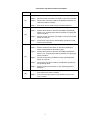
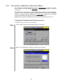
Enabling extension functions by the teach pendant
Access: [F6 Set]—[F7 Options.]—[F8 Extnsion]—
[F5 Input ID]
Enables the extension function. Once enabled, the setting will be retained even if the
controller power is turned off and on.
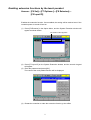
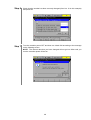
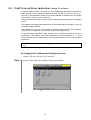
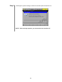
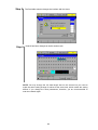
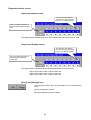
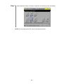
(1) Press [F8 Extnsion] in the Option Menu, and the System Extension window will
appear as shown below.
The serial number appears.
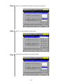
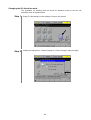
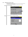
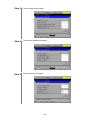
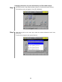
(2) Press [F5 Input ID] on the System Extension window, and the numeric keypad
will appear.
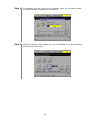
(3) Enter the password and press [OK].
The name of the newly added function will be displayed.
(4) Restart the controller to make the extension function go into effect.
ii
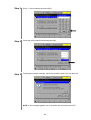
Enabling extension functions in WINCAPSII
Enables the extension function. Once enabled, the setting will be retained even if the
controller power is turned off and on.
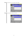
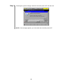
(1) When WINCAPSII and the controller are in connection, choose the “System
Extension” from Help Menu.
(2) The System Extension window appears. Enter the password and press [Add].
The serial number appears.
(3) Restart the controller to make the extension function go into effect.
iii
How the documentation set is organized
The documentation set consists of the following books. If you are unfamiliar with this robot and
option(s), please read all books and understand them fully before operating your robot and option(s).
GENERAL INFORMATION ABOUT ROBOT
Provides the packing list of the robot and outlines of the robot system, robot unit, and robot
controller.
INSTALLATION & MAINTENANCE GUIDE
Provides instructions for installing the robot components and customizing your robot, and
maintenance & inspection procedures.
BEGINNER'S GUIDE
Introduces you to the DENSO robot. Taking an equipment setup example, this book guides
you through running your robot with the teach pendant, making a program in WINCAPSII, and
running your robot automatically.
SETTING-UP MANUAL
Describes how to set-up or teach your robot with the teach pendant, operating panel, or minipendant.
WINCAPSII GUIDE
Provides instructions on how to use the teaching system WINCAPSII which runs on the PC
connected to the robot controller for developing and managing programs.
PROGRAMMER'S MANUAL (I), (II)
Describes the PAC programming language, program development, and command
specifications in PAC.
RC5 CONTROLLER
INTERFACE MANUAL
Describes the RC5 controller, interfacing with external devices, system- and user-input/output
signals, and I/O circuits.
ERROR CODE TABLES
List error codes that will appear on the teach pendant, operating panel, or PC screen if an
error occurs in the robot series or WINCAPSII. These tables provide detailed description and
recovery ways.
OPTIONS MANUAL - this book Describes the specifications, installation, and use of optional devices.
iv
How this book is organized
This book is just one part of the robot documentation set. This book consists of chapters 1 through 12.
PART 1 OPTIONAL OPERATION DEVICES
Describes optional operation devices designed for operating your robot.
Chapter 1
Teaching Pendant
Chapter 2
Operating Panel
Chapter 3
Mini-Pendant (In version 1.7 or later)
Chapter 4
PC Teaching System "WINCAPSII"
PART 2 OPTIONAL BOARDS FOR RC5 CONTROLLER
Describes optional boards that can be installed to the RC5 controller. If you place an order for our robot
system together with these optional boards, those boards will be built in the RC5 controller at the
factory and then the robot system will be delivered.
Chapter 5
Floppy Disk Drive
Chapter 6
µVision Board
Chapter 7
Ethernet Board
Chapter 8
DeviceNet Slave Board
Chapter 9
DeviceNet Master Board
Chapter 10
PROFIBUS-DP Slave Board
Chapter 11
Configuring the RS-232C Extension Board (Recommended Option)
Chapter 12
Mounting Extension Boards
PART 3 OTHER OPTIONS
Describes options except optional operation devices and optional boards.
Chapter 13
Controller Protective Box
v
Contents
Preface.................................................................................................................................................................................i
How the documentation set is organized........................................................................................................................iv
How this book is organized...............................................................................................................................................v
PART 1 OPTIONAL OPERATION DEVICES ........................................................................................................... 1
Chapter1 Teach Pendant ..................................................................................................................................................1
1.1
Teach Pendant Functions ..........................................................................................................................................1
1.2
Names of Teach Pendant Components......................................................................................................................2
1.3
Teach Pendant Specifications....................................................................................................................................3
1.3.1
Specifications .............................................................................................................................................3
1.3.2
Outer Dimensions.......................................................................................................................................4
1.3.3
Pendantless State ........................................................................................................................................5
1.3.4
Connecting and Disconnecting Operating Panel and Teach Pendant ........................................................6
Chapter2 Operating Panel ...............................................................................................................................................8
2.1
Operating Panel Functions ........................................................................................................................................8
2.2
Names of Operating Panel Components ...................................................................................................................9
2.3
Operating Panel Specifications ...............................................................................................................................10
2.4
Mounting and Connecting the Operating Panel ......................................................................................................11
Chapter3 Mini-Pendant (In version 1.7 or later) .........................................................................................................13
3.1
Mini-Pendant Functions..........................................................................................................................................13
3.2
Names of Mini-Pendant Components .....................................................................................................................14
3.3
Mini-Pendant Specifications ...................................................................................................................................15
3.3.1
3.4
Specifications ...........................................................................................................................................15
3.3.2
Outer Dimensions.....................................................................................................................................16
3.3.3
Connecting the Mini-Pendant...................................................................................................................16
Specifications of WINCAPSII Light.......................................................................................................................17
Chapter4 PC Teaching System Software, "WINCAPSII" ..........................................................................................18
4.1
Functions in WINCAPSII .......................................................................................................................................18
4.2
Operating Environment Required ...........................................................................................................................19
4.3
Communications Cable ...........................................................................................................................................20
PART 2 OPTIONAL BOARDS FOR RC5 CONTROLLER .................................................................................... 21
Chapter5 Floppy Disk Drive ..........................................................................................................................................21
5.1
Floppy Disk Drive Functions..................................................................................................................................21
5.2
Floppy Disk Drive Specifications ...........................................................................................................................21
5.3
Location of the Floppy Disk Drive and its Component Names ..............................................................................22
5.4
Mounting the Floppy Disk Drive ............................................................................................................................23
Chapter6 µVision
Board...............................................................................................................................................28
µ
6.1 µVision Board Specifications..................................................................................................................................28
6.1.1
Location of the µVision Board and Names of Connectors .......................................................................30
6.1.2
Block Diagram and Internal Configuration of µVision Board .................................................................31
Peripheral Devices ............................................................................................................................................................33
6.2.1
General Information about the Camera ....................................................................................................33
6.2.2
General Information about the Monitor....................................................................................................35
Chapter7 Ethernet Board...............................................................................................................................................36
7.1
Components in Package ..........................................................................................................................................36
7.2
Ethernet board specifications ..................................................................................................................................36
7.3
Ethernet Board Parts Names ...................................................................................................................................37
7.4
Mounting the Ethernet Board..................................................................................................................................37
Chapter8 DeviceNet Slave Board...................................................................................................................................38
8.1
8.2
8.3
8.4
Overview.................................................................................................................................................................38
8.1.1
Features ....................................................................................................................................................38
8.1.2
Typical Network .......................................................................................................................................38
Product Specifications.............................................................................................................................................39
8.2.1
Names and Functions of Slave Board Components .................................................................................40
8.2.2
General Specifications..............................................................................................................................43
Assignment of Serial I/O Data ................................................................................................................................44
8.3.1
Standard Assignment Mode......................................................................................................................44
8.3.2
Compatible Assignment Mode .................................................................................................................46
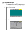
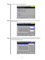
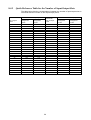
Parameter Entry Procedure .....................................................................................................................................47
8.4.1
Entering the Number of Input/Output Slots .............................................................................................47
8.4.2
Quick Reference Table for the Number of Input/Output Slots .................................................................50
8.5
Field Network Error Indication (Version 1.5 or later).............................................................................................51
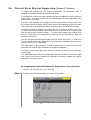
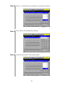
8.6
Network Error Detector Suppression (Version 1.7 or later) ....................................................................................54
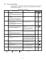
8.7
Error Code Table.....................................................................................................................................................57
Chapter9 DeviceNet Master Board................................................................................................................................60
9.1
9.2
9.3
9.4
Overview.................................................................................................................................................................60
9.1.1
Features ....................................................................................................................................................61
9.1.2
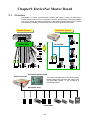
System Configuration Sample..................................................................................................................62
9.1.3
System Construction Procedure ...............................................................................................................63
Product Specifications.............................................................................................................................................64
9.2.1
Names and Functions of Master Board Components ...............................................................................64
9.2.2
General Specifications..............................................................................................................................69
ALLOCATING I/O AREAS ...................................................................................................................................70
9.3.1
I/O Allocation When a DeviceNet Master Board is Installed...................................................................70
9.3.2
Allocation of System Ports.......................................................................................................................71
Building Up a DeviceNet Network .........................................................................................................................73
9.4.1
Network Configuration Sample and Configurators..................................................................................73
9.4.2
Creating a Scanlist....................................................................................................................................76
9.4.3
Changing Master Parameters....................................................................................................................87
9.4.4
Displaying the Master Status....................................................................................................................91
9.4.5
Network Error Indication on DeviceNet Master ......................................................................................95
9.4.6
Allocating Ports Dedicated to the DeviceNet Master...............................................................................97
Chapter10 PROFIBUS-DP Slave Board .....................................................................................................................100
10.1 Overview...............................................................................................................................................................100
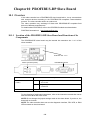
10.1.1 Location of the PROFIBUS-DP Slave Board and Functions of its Components ...................................100
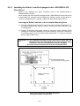
10.1.2 Installing the Robot Controller Equipped with a PROFIBUS-DP Slave Board .....................................101
10.1.3 Specifications .........................................................................................................................................102
10.2 Assignment of Serial I/O Data ..............................................................................................................................102
10.3 Parameter Entry Procedure ...................................................................................................................................103
10.3.1 Entering the Node Address and Number of I/Os with the Teach Pendant ..............................................103
10.3.2 Configuring the Robot Controller from the PC with the PROFIBUS Configurator...............................105
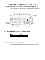
Chapter11 Configuring the RS-232C Extension Board (Recommended Option) ...................................................106
11.1 Recommended RS-232C Extension Board ...........................................................................................................106
11.2 Installing the Extension Board..............................................................................................................................106
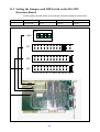
11.3 Setting the Jumpers and DIP Switch on the RS-232C Extension Board ...............................................................107
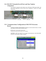
11.4 RS-232C Extended Serial Ports and Line Number Assignment............................................................................108
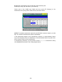
11.5 Communications Configuration of RS-232C Extension Board ............................................................................108
11.6 Coding Sample for Transmission Error Recovery ................................................................................................110
11.7 Limited Warranty ..................................................................................................................................................110
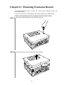
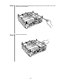
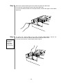
Chapter12 Mounting Extension Boards...................................................................................................................... 111
PART 3 OTHER OPTIONS........................................................................................................................................118
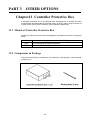
Chapter13 Controller Protective Box.......................................................................................................................... 118
13.1 Models of Controller Protective Box ....................................................................................................................118
13.2 Components in Package ........................................................................................................................................118
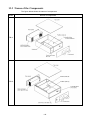
13.3 Names of the Components ....................................................................................................................................119
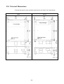
13.4 External Dimensions .............................................................................................................................................120
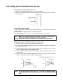
13.5 Setting up the Controller Protective Box ..............................................................................................................121
13.6 Precautions............................................................................................................................................................122
Index
PART 1
OPTIONAL OPERATION
DEVICES
Chapter1 Teach Pendant
The teach pendant is an entry/operation device for creating programs and teaching.
The teach pendant can perform all operations except automatic external operation.
1.1
Teach Pendant Functions
For instructions on how to operate the teach pendant, refer to the SETTING-UP
MANUAL.
Programming and teaching
This function allows you:
- to enter commands and store the robot arm position. You may specify a program
and enter program steps one by one,
- to modify, delete, or copy those commands and robot arm positions, and
- to check edited programs in running them in Teach check mode.
Operating the robot
This function turns power to the motor ON/OFF, executes CAL, starts and stops
automatic operation, and performs manual operation.
Displaying
This function displays the contents of programs, the progress of running programs,
ongoing step number, current robot position or error messages.
1
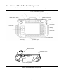
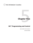
1.2
Names of Teach Pendant Components
The figure below shows the names of the teach pendant components.
R-SEL (Robot selection) switch
LOCK key
M-MOD (Motion mode) key
MOTOR key
SPEED key
ROBOT stop button
Mode selector switch
Jog dial
STOP key
Cancel key
Hand strap
OK key
Cursor keys
Hand strap
Arm traverse keys
LCD screen
SHIFT key
Function keys
Deadman switch
Deadman switch
Back of teach pendant
Names of Teach Pendant Components
2
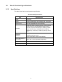
1.3
1.3.1
Teach Pendant Specifications
Specifications
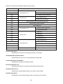
The table below lists the teach pendant specifications.
Teach Pendant Specifications
Item
Specifications
Model
TP-RC5-1
Display
Liquid crystal display with backlight, 640 × 480 pixels
Power source
24 VDC (supplied from robot controller)
Operation
Robot stop button, deadman switch, jog dial, MOTOR
power on/off key, AUTO/MANUAL selector switch,
function keys, arm traverse keys, LOCK key, R-SEL
(robot selection) key, M-MOD (motion mode) key,
SPEED key, cursor keys, STOP key, OK key, Cancel
key
Temperature: 0 to 40°C
Installation
conditions
Humidity: 90% RH or less
(Dew condensation shall not be allowed.)
Outside dimensions
(W x H x D)
260 × 186 × 60 mm (excluding projections)
Weight
1 kg
Cable length
4 m, 8 m, or 12 m
3
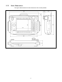
1.3.2
Outer Dimensions
The figure below shows the outer dimensions of the teach pendant.
Outer Dimensions of the Teach Pendant
4
1.3.3
Pendantless State
What is Pendantless State?
The state without having connected the operating panel and the teach pendant to the
robot controller is called a pendantless state.
Setting the Pendantless State
As described below, there are four ways to set the pendantless state:
(1) Turning ON the power to the robot controller without the operating panel and the
teach pendant.
(2) Disconnecting the connected teach pendant.
(3) Disconnecting the connected operating panel.
(4) Disconnecting the connected operating panel and teach pendant.
Caution: Refer to the operation procedures described in Subsection 1.3.4
Connecting and Disconnecting Operating Panel and Teach
Pendant" on the next page when connecting or disconnecting the
operating panel and the teach pendant with the power to the robot
controller ON.
Pendantless State Precautions
Since no teach pendant is connected in the Pendantless state, the robot cannot enter
the manual operation mode or the teach check mode.
The robot is therefore in the Auto mode whenever the Enable Auto input is free. The
external mode cannot be switched, and the program cannot start to run.
When operating the robot in the Pendantless state perform the following steps:
(1) Set the robot not to start to operate when the Enable Auto input is free.
(2) Enable Auto input free state and automatic mode output. Refer to the RC5
CONTROLLER INTERFACE MANUAL, Subsections 4.2.2 and 6.2.2, “Auto Mode
(Output).”
Set the equipment to make an emergency stop in an AND state.
Add (1) and (2) above to the external sequence circuit.
5
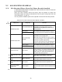
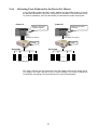
1.3.4
Connecting and Disconnecting Operating Panel
and Teach Pendant
The operating panel and the teach pendant can be connected or disconnected with
the power to the robot controller ON. Connect or disconnect them according to the
procedure described below.
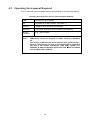
The table below shows the state of change resulting from connecting or
disconnecting the operating panel and/or the teach pendant.
Each letter in the table represents the appropriate connecting and disconnecting
procedure (×: no procedure applicable).
Change of State by Connection and Disconnection
Before
change
After
change
Pendantless
mode
OP connected TP connected
OP and TP
connected
Pendantless
mode
×
(A)
(B)
(A)
OP connected
(D)
×
×
(C)
TP connected
(D)
×
×
×
OP and TP
connected
(D)
(D)
×
×
Caution: The operating panel and the teach pendant cannot be connected or
disconnected while a program is being executed.
6
Connection and Disconnection Procedures
Procedure
(A)
(B)
(C)
(D)
Steps
Step 1
Select the AUTO mode, and activate an emergency stop.
Step 2
Disconnect the connector from CN5 on the robot controller.
Step 3
Connect the connector used for pendantless operation to
CN5 of the robot controller.
Step 4
Error 2187 occurs. Clear it from the external device.
Step 1
Select the AUTO mode, and activate an emergency stop.
Step 2
Perform disconnection. See the SETTING-UP MANUAL,
Section 5.9, "Preparing the Robot Controller to Unplug the
Teach Pendant."
Step 3
Disconnect the connector from CN5 on the robot controller
within 15 seconds.
Step 4
Connect the connector for Pendantless operation to CN5
on the robot controller.
Step 1
Set the mode selector switch on the operating panel to TP.
Step 2
Set the mode selector switch on the teach pendant to
AUTO, and activate an emergency stop.
Step 3
Perform disconnection. See the SETTING-UP MANUAL,
Section 5.9, "Preparing the Robot Controller to Unplug the
Teach Pendant."
Step 4
Disconnect the teach pendant from the operating panel
within 15 seconds.
Step 5
Connect the connector used for Pendantless operation to
the operating panel.
Step 6
Set the mode selector switch on the operating panel to
MANUAL.
Step 1
Disconnect the connector used for pendantless operation
from CN5 on the robot controller.
Step 2
Connect the operating panel or teach pendant to CN5 on the
robot controller.
7
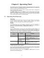
Chapter2 Operating Panel
The operating panel is a fixed type operation console that allows you to recover the
robot from a stop due to problems caused by peripheral units, etc. The panel has
minimum necessary teaching/operating functions.
To the operating panel you may connect a teach pendant which is designed for
teaching and other fine operations.
The ROBOT STOP button and the STOP key on the operating panel and the teach
pendant are available anytime. For other functions, you may select the operating
panel or teach pendant. To switch between the operating panel and teach pendant,
use the mode selector switch on the operating panel.
2.1
Operating Panel Functions
Operating
The operating panel provides these functions--motor power ON/OFF, CAL execution,
program selection, speed change, automatic operation start/stop and manual
operation. For further information, see the SETTING-UP MANUAL.
Display
The operating panel has an LCD capable of displaying 2 lines of 16 characters. It
displays the current robot position, ongoing program number, error code when an
error occurs, and related information in alphanumerical characters.
Teaching
With the operating panel, you may run the robot manually and start programs. As
listed below, you may also edit variables, get robot arm positions into variables in
teaching, and move the robot arm by specifying a desired variable, depending upon
the version of the main software. Choosing work coordinates or tool coordinates is
also possible. For details, refer to the SETTING-UP MANUAL.
Version of main
software
Version 1.2 or later
Version 1.4 or later
Version 1.6 or later
Function
Editing variables
Teaching the current
position
Choosing work
coordinates or tool
coordinates
Operating the robot
arm by specifying a
desired variable
Description
You may edit variables by entering
numerical values.
You may get the current position into P
variables, J variables, and T variables. It
is used for position teaching.
You may choose work coordinates or tool
coordinates.
You may move the robot arm according
to the specified variable. It is used to
confirm variables you have preset in
teaching.
Connecting the Teach Pendant
You may connect the teach pendant to the TP terminal at the bottom of the operating
panel. Setting the mode selector switch on the operating panel to the TP position
allows you to operate the robot from the teach pendant.
When the mode selector switch is set to the MANUAL or AUTO position, the robot is
operated from the operating panel.
8
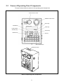
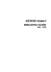
2.2
Names of Operating Panel Components
The figure below shows the names of the operating panel components.
Mode selector switch
ROBOT STOP button
SHIFT key
M-MOD key
STOP key
R-SEL (Robot
selection) key
Cancel key
MOTOR key
OK key
Arm traverse keys
Deadman switch
Names of Operating Panel Components
9
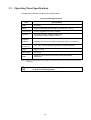
2.3
Operating Panel Specifications
The table below lists the operating panel specifications.
Operating Panel Specifications
Item
Specifications
Model
OP-RC5-1
Display
Liquid crystal display with backlight, 16 characters × 2 lines
Power source
24 VDC (supplied from robot controller)
Operation
23 flat key switches, ROBOT STOP button,
mode selector switch, deadman switch
Installation
conditions
Temperature: 0 to 40°C
Humidity: 90% RH or less (Dew condensation shall not be allowed.)
Dimensions
(H x W x D)
140 × 100 × 40 mm (Excluding projections such as switches)
Weight
Approx. 0.7 kg
Cable length
4 m or 8 m
Others
Equipped with a socket for connecting the teach pendant
(See Note.)
(Note) When no teach pendant is connected, a pendantless connector should be connected to the
TP socket.
Caution:
The operating panel is a fixed type operation console. Be sure
to secure it to the equipment.
10
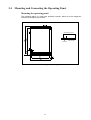
2.4
Mounting and Connecting the Operating Panel
Mounting the operating panel
The operating panel is a fixed type operation console. Mount it to the equipment,
referring to the figure given below.
Operating panel face
(5 mm or more)
To be secured
from the rear
M4 screw
Mounting the Operating Panel
11
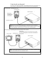
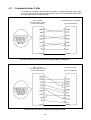
Connecting the operating panel
As shown in the figure given below, the operating panel can be connected to the
robot controller. A teach pendant can also be connected to the operating panel.
Connection type 1: Operating panel only
Operating panel
Robot controller
Mode switch
Turn this switch to
the MANUAL or
AUTO position.
Pendantless connector
NOTE: Be sure to secure the operating panel to a safe place such as equipment.
NOTE: When using the operating panel without the teach pendant connected, always
insert the pendantless connector into the TP socket on the operating panel.
Connection type 2: Operating panel connected with the teach pendant
Mode switch
Operating panel
Teach pendant
To use the teach pendant, turn this switch to the TP position.
To use the operating panel, turn this switch to the MANUAL or
AUTO position.
Robot controller
NOTE: The total cable length must not be more than 12 m when the operating panel
and the teach pendant are to be connected in series.
Connecting the Operating Panel to the Robot Controller and the Teach Pendant
12
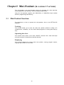
Chapter3 Mini-Pendant (In version 1.7 or later)
The mini-pendant is an entry/operation device for operating the robot manually,
starting programs, and teaching. It has no programming function.
Using the mini-pendant together with WINCAPSII or WINCAPSII Light enables
efficient programming and teaching.
3.1
Mini-Pendant Functions
For instructions on how to operate the mini-pendant, refer to the SETTING-UP
MANUAL.
Teaching
This function allows you to store the robot arm position (limited to editing of P
variables and J variables). You can check edited programs in running them step by
step.
Operating the robot
This function turns power to the motor ON/OFF, executes CAL, starts and stops
automatic operation, and performs manual operation.
Displaying
This function displays the current robot arm position, running program number,
ongoing step number or error codes.
13
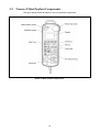
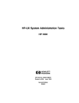
3.2
Names of Mini-Pendant Components
The figure below shows the names of the mini-pendant components.
Names of Mini-Pendant Components
14
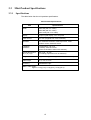
3.3
3.3.1
Mini-Pendant Specifications
Specifications
The table below lists the mini-pendant specifications.
Mini-Pendant Specifications
Item
Specifications
Model
MP5J4K (with 4 m cable)
MP5J8K (with 8 m cable)
MP5J12K (with 12 m cable)
Display
Liquid crystal display, 128 × 64 pixels
Power source
24 VDC (supplied from robot controller)
Operation
33 membrane switches, robot stop button, mode
selector switch, deadman switch
Installation
conditions
Temperature: 0 to 40°C
Humidity: 90% RH or less
(Dew condensation shall not be allowed.)
Outside dimensions
(W) x (H) x (D)
86 x 218 × 38 mm
(excluding projections such as switches)
Weight
Approx. 0.3 kg (excluding cables. See Note below.)
Cable length
4 m, 8 m, or 12 m
Accessory
WINCAPSII Light
Note: Cable weight
Approx. 0.2 kg (4 m), 0.4 kg (8 m), 0.6 kg (12 m)
15
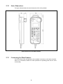
3.3.2
Outer Dimensions
The figure below shows the outer dimensions of the mini-pendant.
Outer Dimensions of the Mini-Pendant
3.3.3
Connecting the Mini-Pendant
You may connect the mini-pendant to the "pendant" connector on the robot controller.
When it is connected, neither the teach pendant nor operating panel can be used
concurrently.
16
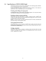
3.4
Specifications of WINCAPSII Light
WINCAPSII Light that comes with the mini-pendant is PC teaching system software.
It is a functionally limited version of WINCAPSII.
Except that WINCAPSII Light is limited to the following functions, it is the same as
WINCAPSII. Refer to WINCAPSII given in the next chapter.
Entering and editing robot programs
In WINCAPSII Light, you may enter or edit robot programs. You may also develop
new programs by making use of existing programs.
Reading/writing programs and data
WINCAPSII Light may read programs, variables, coordinate values, CALSET data,
log data, and other data from the robot controller and display them on the PC screen
or can write them to the robot controller.
NOTE: To use this function, the robot controller and the PC must be connected with
each other using a communications cable.
Saving programs and data
WINCAPSII Light may store programs, CALSET data, log data, and other data onto
the hard disk or floppy disks. It may also read out those stored data and re-edit or
write them to the robot controller.
Getting a snapshot
WINCAPSII Light may get a snapshot containing robot motion data from the robot
controller and display the robot motion at one particular point in time on the PC
screen, enabling you to check it.
17
Chapter4
PC Teaching System Software, "WINCAPSII"
The PC teaching system facilitates the creation and editing of robot programs. Use
this system to improve creation and/or robot management programs. For further
information about how to use this teaching system, refer to the WINCAPSII GUIDE.
4.1
Functions in WINCAPSII
WINCAPSII has the following functions:
Entering and editing robot programs
In WINCAPSII, you may enter or edit robot programs. You may also develop new
programs by making use of programs supplied as a library or with existing programs.
Reading/writing programs and data
WINCAPSII may read programs, variables, coordinate values, CALSET data, log
data, and other data from the robot controller and display them on the PC screen or
can write them to the robot controller.
NOTE: To use this function, the robot controller and the PC must be connected with
each other using a communications cable.
Saving programs and data
WINCAPSII may store programs, CALSET data, log data, and other data onto the
hard disk or floppy disks. It may also read out those stored data and re-edit or write
them to the robot controller.
Printing programs and data
If you connect a printer to the PC, WINCAPSII may print out programs, CALSET
data, log data, and other data.
Simulating the robot motion
WINCAPSII may simulate the robot motion in animation on the PC screen.
NOTE: To use this function, the robot controller and the PC must be connected with
each other using an interface cable.
During automatic operation or manual operation using the teach pendant, the
simulated image moves corresponding to the actual robot motion.
18
4.2
Operating Environment Required
The PC teaching system software requires the operating environment listed below.
Operating Environment for the PC Teaching System Software
CPU
Pentium or higher capacity
OS
Windows 95 or upper version (See Note 1.)
Memory
32 MB or more (64 MB recommended)
Hard disk
A free area of 80 MB or more is required at installation.
Monitor
resolution
640 × 480 or higher
Note 1
WINCAPSII cannot run properly on earlier versions of Windows
95.
The version of Windows 95 can be checked with [Control Panel –
System – Information]. If A, B or C is not displayed (no symbol) at
the end of the version information (4.00, 95B), update your
Windows 95 with the Windows 95 Service Pack 1 that is available
from the Microsoft's web site.
19
4.3
Communications Cable
To enable the computer and the robot controller to communicate with each other,
they must be connected with a communications cable. Use the appropriate RS-232C
for cross cable wiring, as shown below.
Robot controller
CN1 (RS-232C) connector
(9-pin D-SUB female)
Computer (IBM PC compatible)
(9-pin D-SUB female)
View from the
cable side
Frame
Frame
Shield
RS-232C Communication Cable Wiring Diagram (IBM PC compatible)
Robot controller
CN1 (RS-232C) connector
(9-pin D-SUB female)
Computer (PC-98)
(25-pin D-SUB male)
View from the
cable side
Frame
Shield
RS-232C Communications Cable Wiring Diagram (PC-98)
20
Frame
PART 2 OPTIONAL BOARDS FOR RC5
CONTROLLER
Chapter5 Floppy Disk Drive
The floppy disk drive is an optional storage device that stores or reads data such as
robot programs, to/from a floppy disk. It may be built in the robot controller.
5.1
Floppy Disk Drive Functions
The floppy disk drive has the following functions:
Formatting
This function initializes a floppy disk so that it can store data. You need to initialize a
new floppy disk before use.
Floppy disks will be initialized in MS-DOS format.
Saving
This function stores programs, CALSET data, etc. from the robot controller onto a
floppy disk.
Loading
This function reads programs, CALSET data, etc. from a floppy disk to the robot
controller.
Caution NEVER load the CALSET data prepared for other robots.
loaded, the robot will malfunction. It is DANGEROUS.
5.2
Floppy Disk Drive Specifications
The table below lists the specifications of the built-in floppy disk drive.
Table 3-6 Built-in Floppy Disk Drive Specifications
Item
Power source
Environmental conditions
Weight
Specifications
5 VDC (supplied from the robot controller)
Temperature : 5 to 40°C
Humidity : 20% to 80% (without dew condensation)
155 g (body alone)
Type
Applicable floppy disk
Storage
capacity
21
2HD, 3.5-inch floppy disk
1.44 MB
If
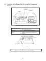
5.3
Location of the Floppy Disk Drive and its Component
Names
Floppy disk
insertion slot
Eject button
Indicator
Location of the Floppy Disk Drive and its Component Names
Floppy disk insertion slot
Insert a floppy disk through this slot.
(See the figure given below.)
Eject button
Push this button to eject the floppy disk.
Indicator
This lamp comes ON when the floppy disk is
accessed.
Notch
Inserting direction
Inserting a Floppy Disk
Caution: Do not eject the floppy disk when the indicator is lit. Doing so will
damage or destroy data stored on the floppy disk.
22
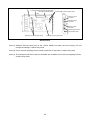
5.4
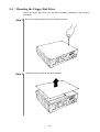
Mounting the Floppy Disk Drive
Mount the floppy disk drive into the robot controller according to the following
procedure:
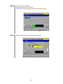
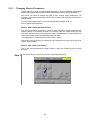
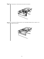
Step 1
Remove the eight screws from the controller top cover.
Step 2
Lift the top cover up and off the robot controller.
23
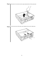
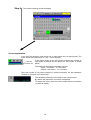
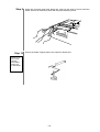
Step 3
Remove the four screws from the upper plate and take off the upper plate.
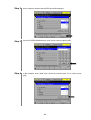
Step 4
Push the two pins of the blank cap outwards and remove the blank cap.
24
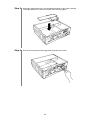
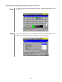
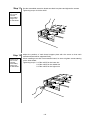
Step 5
Mount the floppy disk drive in the appropriate position of the robot controller.
The floppy disk drive is secured to a disk drive mounting plate.
Step 6
Secure the front panel of the floppy disk drive with two screws.
25
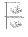
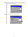
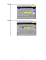
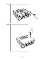
Step 7
Secure the floppy disk drive mounting plate with four screws.
Step 8
Connector J6 FDD 26P on the printed circuit board has a cable lock.
If the connector is locked, lift and unlock it. The lock is made of resin. Do not apply
excessive force to it since the lock could easily break. Handle it with extra care.
Fully insert the flat cable of the floppy disk drive into connector J6 FDD 26P on the
circuit board. If the flat cable is inserted fully, the blue line marked on the
connecting section will become aligned with the top edge of the connector.
26
Step 9
Step 10
Securely push in the connector lock.
Put the top cover and secure it with eight screws.
The mounting of the floppy disk drive is completed.
27
Chapter6 µVision Board
6.1
µVision Board Specifications
If the robot controller has a built-in µVision board, it can handle a variety of image
processor functions.
Similar to other commands, image processing commands are already incorporated
and no special operations or programming are required.
µVision Board Specifications
Item
Specifications
CPU
32-bit CPU
Image storage memory
for processed images
(Horizontal x Vertical)
512 × 480 pixels, 8 bits × 4 screens
Overlay memory
for drawn images
(Horizontal x Vertical)
624 × 480 pixels, 2 bits × 2 screens
Search model registration
memory
1 MB (H255 × V255 × 8 models), Up to 100 models registrable
Image input,
number of channels
EIA/CCIR monochrome, 256 gradations, 2 channels
Image output
EIA/CCIR monochrome, 256 gradations, 1 channel
Image processing
Binary feature extract
(area, center of gravity, main axis angle, luminance integration), histogram,
edge detection, image-to-image operation, filtering, labeling,
light/dark image search, code recognition (QR code)
Processing range
specification (window)
Up to 512 windows registrable
(shape: straight line, rectangle, circle, ellipse, sector)
Self-diagnosis function
Memory check, incorrect input, incorrect processing range,
improper camera connection, etc.
Error display
Errors will be displayed on the teach pendant (option).
Power source
5 VDC, 12 V (supplied from controller ISA)
Temperature: 0 to 40°C
Environmental conditions
(during operation)
Outside dimensions
(H x W x D)
Humidity: 90 %RH or less
(Dew condensation shall not be allowed.)
21.4 × 114 × 185 mm (excluding projections of connectors)
Note (1) The number of registrable models will differ depending upon the model image and/or size.
(2) Since power is supplied from the inside of the robot controller, no external power source is required.
28
Note (1)
Note (2)
Operating condition setting switch (all off)
Program adjustment connector (Not used.)
Camera trigger short pins (Not used.)
ISA mapping switch (fixed)
Camera 1 input
connector
Camera 2 input
connector
Monitor output
connector
Serial port (Not used.)
I/O port (Not used.)
Extension connectors (Not used.)
Interrupt short pin (Not used.)
µVision Board
Note (1) Switches and the short pins on the µVision board have been set at the factory. Do not
change the settings. A failure may result.
Note (2) Do not connect anything to the unused connectors on the board. A failure may result.
Note (3) The serial port and the I/O port on the board are unusable. Do not connect anything to them.
A failure may result.
29
6.1.1
Location of the µVision Board and Names of Connectors
Insert a µVision board into extension slot 3 shown in the figure below.
Inserting the board in a wrong slot may damage the internal circuits of the robot
controller. For the installation procedure, refer to Chapter 11, "Mounting Extension
Boards."
Extension slot 1
Extension slot 2
Extension slot 3
(µVision board)
I/O port
(TTL I/O not used)
Serial port
(RS-232C not used)
Monitor output connector
Camera input connector 1
Camera input connector 2
Location of µVision Board and Names of Connectors
Camera input connector 1
Used for connection with camera 1 (12-pin, round
connector)
Camera input connector 2
Used for connection with camera 2 (12-pin, round
connector)
Monitor output connector
Used for connection with the monitor (BNC).
Serial port
RS-232C port (Not used.)
I/O port
TTL level input/output: 1 point each (Not used.)
Camera Input Connector Pin Layout
(Manufacturer: Hirose Electric HR10A-10R-12S or equivalent)
Pin No.
1
Signal name
GND
2
+12V
Camera power 12V
3
GND
Camera power GND
4
VIDEO
Video signal
5
HDGND
HD synchronous signal GND
6
HD
Horizontal synchronous signal
7
VD
Vertical synchronous signal
8
NC
Not connected
9
NC
Not connected
10
NC
Not connected
11
TRIG
12
VDGND
Remarks
Camera power GND
Trigger signal (not used)
VD synchronous signal GND
30
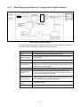
6.1.2
Block Diagram and Internal Configuration of µVision Board
Animation
(camera image)
Camera 1
Selector
A/D
LT
Selector
LT
Overlay circuit
(superpose)
D/A
Monitor
Camera 2
Image storage
memory
(4 processed
screens)
Static image
(image memory)
Image
processing
circuit
Drawn image
CPU
Dedicated drawn image
memory (2 screens)
Block Diagram of µVision Board
The above figure illustrates the processing flow of the µVision board as a reference.
The actual circuit configuration is different from this diagram.
Camera selector
Switches between camera 1 and 2.
A/D
Converts analog signals into digital signals (8-bit).
Monitor selector
Selects whether to display the camera live image or static image
on the monitor.
LT
Converts 8-bit data values using the appropriate table.
Overlay circuit
Overlays a drawn image, which is stored in the dedicated drawn
image memory, on the camera live image or static image (see the
figure given on the next page).
D/A
Converts digital data into analog signals.
Image storage
memory
Stores camera live images. When outputted onto the monitor
screen, those images will be handled as static images. Up to four
screens can be stored on this board.
Dedicated drawn
image memory
Stores drawn images of characters and figures. Those images
can be displayed on the monitor screen via the overlay circuit. Up
to two screens can be stored on this board.
Image processing
circuit
Processes images.
CPU
Manages the entire system.
31
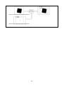
X = 280
Y = 245
Overlaying
(superpose)
Camera and processed screen image (256 gradations)
X = 280
Y = 245
Camera and processed screen image (256 gradations)
Overlay Concept
32
6.2
Peripheral Devices
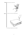
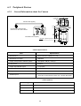
6.2.1
General Information about the Camera
C mount
Camera cable (option)
4-M3 depth 3.5 (tightening torque: 0.69 N⋅m)
Connect to the camera input
connector on the µVision board
CS-8320B camera (back)
4-M2 depth 3 (tightening torque: 0.39 N⋅m)
Camera Dimensions and its Parts Names
Camera Specifications
Item
Specifications
Manufacturer
Tokyo Electronic Industry Co., Ltd.
Manufacturer’s model
CS8320B
Image pickup interline transfer system
CCD pixels: 768 (H) × 493 (V)
Lens mount
C mount
Image output NTSC signal
1.0 Vp-p/75 Ω
Power source/Ambient temperature
Supplied from power adapter, 0 to +40°C
Weight
120 g
Vibration-proof
98 m/s, 10G
(10 to 50 Hz, 30 minutes in each of X, Y and Z directions)
Cables (Option)
Cable length
Camera cable model
3m
CPC3440-03
5m
CPC3440-05
15 m
CPC3440-15
33
Caution (1) When mounting the camera to the equipment, tighten the screws
securely to the specified torque. See the figure given on the
previous page.
(2) Do not apply a strong impact or vibration to the camera. A failure
may result.
(3) When opening the camera top cover and changing the settings,
be sure to turn the controller power off or disconnect the camera
cable.
(4) For setting up cameras, refer to the instruction manual that
comes with the camera.
34
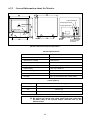
6.2.2
General Information about the Monitor
Input impedance
Image signal output
Image signal input
Adjuster cover
Power switch
Pilot lamp
BNC cable
To µvision board
monitor output
connector
Monitor Dimensions and its Parts Names
Monitor Specifications
Item
Specifications
Manufacturer
Chuo Musen Co., Ltd.
Manufacturer’s model
TMP-233-03
Cathode-ray tube
9-inch, monochrome
Image input NTSC signal
0.7 Vp-p (straight polarity)
Power supply
100 VAC, 50/60 Hz
Power consumption
Approx. 30 W
Ambient temperature
0 to 40°C
Humidity
90% or less (without dew condensation)
Cables (Option)
Cable length
BNC coaxial cable type
1m
3CV-PP (1)
3m
3CV-PP (3)
5m
3CV-PP (5)
Caution
(1) NEVER disassemble the monitor.
(2) Be sure to set a ferrite core clamp (ZCAT1518) that comes with
the BNC cable, to the monitor output connector side on the
µVision board.
35
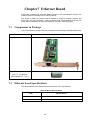
Chapter7 Ethernet Board
If the robot controller has a built-in Ethernet board, it can communicate with the PC
teaching system according to the TCP/IP protocol.
This board is helpful for communication between a single PC teaching system and
more than one robot controller. It also provides faster communication than an RS232C cable, contributing to improved response of the PC teaching system.
7.1
Components in Package
Check that following components are contained in the package of the Ethernet board.
Components
Appearance
Ethernet board
Ferrite clamp sleeve
(RFC-10 KITAGAWA
INDUSTRIES CO. , LTD.)
7.2
Ethernet board specifications
The specifications of the Ethernet board are shown in the figure below.
Ethernet Board Specifications
Item
Specifications
Connection
10BaseT (IEEE 802.3)
Baud rate
10 Mbits/sec.
36
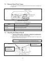
7.3
Ethernet Board Parts Names
The parts names of the Ethernet board and its functions are shown in the figure and
the table below.
Ethernet Board Parts Names
LEDs and Connector on the Ethernet Board
Name
Function
Link LED
Lights if the UTP port detects a signal.
CRS LED
Lights if a carrier signal is detected. This LED will remain ON if no cable is
connected to the UTP connector.
RJ-45 UTP connector
Used for 10BaseT connection.
7.4
Mounting the Ethernet Board
(1)
Insert the Ethernet board in extension slot 1 (upper slot) or extension slot 2
(middle slot) on the controller. For installation procedure of the Ethernet board,
refer to Chapter 11, "Mounting Extension Boards."
(2) Attach the ferrite clamp sleeve onto the cable and connect the cable to the
controller as shown in the figure below.
Caution:
Fix the cable not to stress onto the connector. The stress
onto the connector may occur communication error.
Fix the cable not to stress
onto the connector.
Extension slot 1 or 2
Ferrite clamp sleeve
(Fixing position:
Approximate 10 cm
from the connector)
37
Chapter8 DeviceNet Slave Board
8.1
Overview
If the robot controller has a built-in DeviceNet slave board, it can communicate with
external devices according to the DeviceNet-compliant protocol.
As a slave unit for serial communications which is compliant with the open network
DeviceNet, the robot controller may easily exchange I/O data with a variety of
DeviceNet-compliant control devices of many manufacturers.
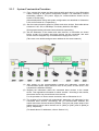
8.1.1
Features
(1) DeviceNet-compliant
The DeviceNet is an internationally open network developed by Allen-Bradley and is
designed to allow control devices (e.g., sensors and actuators) to communicate with
each other.
(2) Can be networked with control devices of various manufacturers
The robot controller equipped with DeviceNet slave board can be networked with
DeviceNet-compliant control devices of various domestic and foreign manufacturers
since the communications specifications are open.
(3) Easy wiring and maintenance
The 5-core special cable and detachable connector of the DeviceNet slave board
make it easy to install wiring between nodes (communications units) and
disassembly/restructure the network. This will sharply reduce cost in wiring and
maintenance, as well as making replacement of units easy at the time of failure.
(4) Sufficient number of I/Os
The controller is capable of handling a large quantity of I/O data as listed below.
Further, increase or decrease of the number of user-input I/Os is possible in units of 8
steps.
Number of I/Os
Transmission
Reception
8.1.2
Standard assignment mode
24 to 224
Compatible assignment mode
24 to 224
Standard assignment mode
24 to 216
Compatible assignment mode
40 to 232
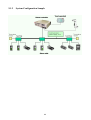
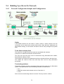
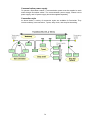
Typical Network
The figure below illustrates a typical network.
PLC
(Programmable controller)
Control panel
Field unit
38
This controller
FA computer
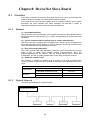
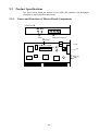
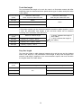
8.2
Product Specifications
The figure below shows the location of the LEDs, DIP switches, and DeviceNet
connector on the DeviceNet slave board.
Viewed from X
(A)
LEDs
(C)
DeviceNet connector
⇐X
(B)
DIP switch
(C)
(A)
BR
39
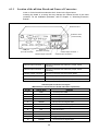
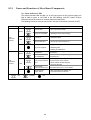
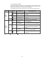
8.2.1
Names and Functions of Slave Board Components
(A) Status indicator LEDs
The status indicators MS and NS ("A" in the figure given on the previous page) can
light or flash in green or red. Each of the ON, flashing, and OFF states of those
indicators shows the module or network status as listed below.
The flashing interval is once per second (0.5 second of ON and 0.5 second of OFF).
LED name
Color
State
Definition
Explanation
Normal state
• The unit works normally.
Setup not completed
• Reading the DIP switch settings.
Fatal error
• Hardware failure.
Recoverable error
• Wrong DIP switch settings, etc.
Green
MS
(Module
Status)
Red
• No power is supplied to the DeviceNet module.
−
No power supplied
• Resetting data.
Communications link
established
The network is working normally. (The line is
connected.)
Communications link
not established
The network is working normally, but the line is not
connected yet.
• Waiting for initialization.
Green
NS
(Network
Status)
Fatal communications
error
Red
• Node address double-assigned.
• "Bus off" detected.
−
: ON
The unit detects any error disabling
communication on the network.
: Flashing
Recoverable
communications error
Communications error in some slaves.
Network power
supply failure
• Not connected to the master unit.
• Communications line broken.
: OFF
40
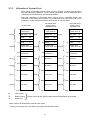
(B) DIP switch (SW101)
Use the DIP switch for setting the node address and bit rate as shown below.
Node address setting
Bit rate setting
DIP Switch Setting
NOTE: Always turn off the controller power (including the network power) before
setting the DIP switch.
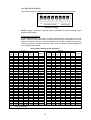
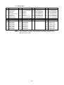
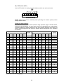
Setting the node address
Set the node address of the robot controller using selectors 1 through 6 of the DIP
switch, referring to the table below. You may freely set any of 0 through 63 to a node
address unless the address is double-assigned on the same network including the
master and slaves. Double assignment will cause an address double-assignment
error, disabling the network.
Node Address Setting by the DIP Switch
1
(32)
0
0
0
0
0
0
0
0
0
0
0
0
0
0
0
0
0
0
0
0
0
0
0
0
0
0
0
0
0
0
0
0
Note 1 :
DIP switch
DIP switch
Node
Node
2
3
4
5
6
1
2
3
4
5
6
address
address
(16)
(8)
(4)
(2)
(1)
(32)
(16)
(8)
(4)
(2)
(1)
0
0
0
0
0
0
0
0
0
0
0
0
32
0
0
0
0
1
1
0
0
0
0
0
1
33
0
0
0
1
0
2
0
0
0
0
1
0
34
0
0
0
1
1
3
0
0
0
0
1
1
35
0
0
1
0
0
4
0
0
0
1
0
0
36
0
0
1
0
1
5
0
0
0
1
0
1
37
0
0
1
1
0
6
0
0
0
1
1
0
38
0
0
1
1
1
7
0
0
0
1
1
1
39
0
1
0
0
0
8
0
0
1
0
0
0
40
0
1
0
0
1
9
0
0
1
0
0
1
41
0
1
0
1
0
10
0
0
1
0
1
0
42
0
1
0
1
1
11
0
0
1
0
1
1
43
0
1
1
0
0
12
0
0
1
1
0
0
44
0
1
1
0
1
13
0
0
1
1
0
1
45
0
1
1
1
0
14
0
0
1
1
1
0
46
0
1
1
1
1
15
0
0
1
1
1
1
47
1
0
0
0
0
16
0
1
0
0
0
0
48
1
0
0
0
1
17
0
1
0
0
0
1
49
1
0
0
1
0
18
0
1
0
0
1
0
50
1
0
0
1
1
19
0
1
0
0
1
1
51
1
0
1
0
0
20
0
1
0
1
0
0
52
1
0
1
0
1
21
0
1
0
1
0
1
53
1
0
1
1
0
22
0
1
0
1
1
0
54
1
0
1
1
1
23
0
1
0
1
1
1
55
1
1
0
0
0
24
0
1
1
0
0
0
56
1
1
0
0
1
25
0
1
1
0
0
1
57
1
1
0
1
0
26
0
1
1
0
1
0
58
1
1
0
1
1
27
0
1
1
0
1
1
59
1
1
1
0
0
28
0
1
1
1
0
0
60
1
1
1
0
1
29
0
1
1
1
0
1
61
1
1
1
1
0
30
0
1
1
1
1
0
62
1
1
1
1
1
31
0
1
1
1
1
1
63
Selector OFF and ON are expressed by 0 and 1, respectively. (Before shipment from the factory, the node address
is set to 0 by default.)
41
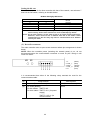
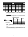
Setting the bit rate
To match the bit rate of the robot controller with that of the network, use selectors 7
and 8 of the DIP switch, referring to the table below:
Bit Rate Setting By DIP Switch
Selectors on the DIP switch
Selector 7
Selector 8
0
0
0
1
1
0
1
1
Bit rate
125 kbps
250 kbps
500 kbps
500 kbps
Note 1: Selector OFF and ON are expressed by 0 and 1, respectively. (Before shipment
from the factory, both of these selectors are set to 0 (=500 kbps) by default.
Note 2: On the same network, set the same bit rate to all nodes (master and slaves).
Otherwise, slaves whose bit rate is different from that of the master cannot
communicate only, but also they may cause a communications error between
correctly set nodes.
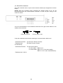
(C) DeviceNet connector
The robot controller uses an open screw connector whose pin arrangement is shown
below.
NOTE: When the controller power (including the network power) is on, do not
disconnect/connect the communication connector or touch its pins. Doing so will
result in a failure.
1 2
1: V
2: CAN _ L
3: Drain
4: CAN _H
5: V+
3 4 5
(Black)
(Blue)
(Shield)
(White)
(Red)
It is recommended that either of the following crimp terminals be used for the
communications cable.
No.
Crimp terminal
Tools required
(1)
AI series (Phoenix Contact)
ZA3 (Phoenix Contact)
(2)
TC series (Nichifu)
NH-32
For thin cables: TME TC-0.5
For thick cables: TME TC-2-11 (for power
supply)
TME TC-1.25-11 (for
communication)
42
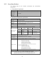
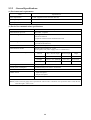
8.2.2
General Specifications
The following
specifications.
tables
list
the
controller
environmental
and
communication
(1) Environmental requirements
Item
Power
requirements
Operating
temperature
Operating
humidity
Specifications
5 VDC (supplied via the controller ISA bus)
0 to 40°C
90% RH or less (without condensation)
(2) DeviceNet communications specifications
Item
Communications
protocol
Connection
supported
Connection type
(Note 1)
Bit rate
Communications
media
Communications
cable length
Power supply for
communication
Internal power
consumption
Max. number of
connectable nodes
Number of I/Os
Specifications
DeviceNet-compliant
Master/slave connection : Polling I/O function
Compliant with DeviceNet communications rules
Multi-drop type with possible combination of T-branch
(to trunk and branch lines)
500, 250, 125 kbps (selectable by switch)
Special cable consisting of 5 wires
(2 for signals, 2 for power supply and 1 as a shield wire)
Max. network
Branch
Bit rate
Total branch length
length
length
500 kbps 100 m or less
6 m or less
39 m or less
(Note 2)
250 kbps 250 m or less
6 m or less
78 m or less
(Note 2)
125 kbps 500 m or less
6 m or less
156 m or less
(Note 2)
External supply of 24 VDC ±10%
Communication power source: 30 mA max.
64 nodes (including configurator (converter) if connected)
Standard assignment mode:
40 points for system input
32 points for system output
24 points to 216 for user input
24 to 224 points for user output
The number of I/Os can be set in unit of 8 points.
Compatible assignment mode:
24 points for system input
32 points for system output
40 to 232 points for user input
24 to 224 points for user output
The number of I/Os can be set in unit of 8 points.
Error check
CRC
(Note 1) Terminator resistors are needed at both ends of the trunk line.
(Note 2) These values may apply when a special thick cable is used as a trunk line. If a
special fine cable is used, the max. network length is 100 m or less.
43
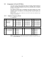
8.3
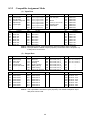
Assignment of Serial I/O Data
Two types of serial I/O data assignment modes are available--standard assignment
mode and compatible assignment mode (which is compatible with our previous
models). In each of those assignment modes, serial input/output data are assigned
as shown in [ 1 ] and [ 2 ].
The controller equipped with a DeviceNet slave board transfers the system
input/output data only through the DeviceNet, disabling the parallel ports. The
controller, however, can handle the user input/output data using both parallel ports
and DeviceNet.
Signals such as robot stop, enable auto, and CPU normal are transferred only
through the parallel ports.
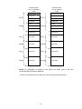
8.3.1
Standard Assignment Mode
(1) Input Data
No.
512
513
514
515
516
517
518
519
No.
544
545
546
547
548
549
550
551
Content
Step stop (all tasks)
–
Halt (all tasks)
Strobe signal
Skip interrupt
–
–
Command data odd
parity
Content
Bit 0 in command area
Bit 1 in command area
Bit 2 in command area
Bit 3 in command area
–
–
–
–
No.
520
521
522
523
524
525
526
527
Content
Bit 0 in data area 1
Bit 1 in data area 1
Bit 2 in data area 1
Bit 3 in data area 1
Bit 4 in data area 1
Bit 5 in data area 1
Bit 6 in data area 1
Bit 7 in data area 1
No.
552
553
554
555
556
557
558
559
Content
INPUT 552
INPUT 553
INPUT 554
INPUT 555
INPUT 556
INPUT 557
INPUT 558
INPUT 559
No.
528
529
530
531
532
533
534
535
Content
Bit 0 in data area 2
Bit 1 in data area 2
Bit 2 in data area 2
Bit 3 in data area 2
Bit 4 in data area 2
Bit 5 in data area 2
Bit 6 in data area 2
Bit 7 in data area 2
No.
536
537
538
539
540
541
542
543
Content
Bit 8 in data area 2
Bit 9 in data area 2
Bit 10 in data area 2
Bit 11 in data area 2
Bit 12 in data area 2
Bit 13 in data area 2
Bit 14 in data area 2
Bit 15 in data area 2
No.
760
761
762
763
764
765
766
767
Content
INPUT 760
INPUT 761
INPUT 762
INPUT 763
INPUT 764
INPUT 765
INPUT 766
INPUT 767
Note 1: Numerals in the No. column denote the I/O port numbers of the controller.
Note 2: The input data is handled in bytes (8 points). The default is 64 points. Up to 256
points can be used.
44
(2) Output Data
No.
768
769
770
771
772
773
774
775
No.
800
801
802
803
804
805
806
807
Content
Content
Robot warning
Auto mode
External mode
Battery warning
No.
776
777
778
779
780
781
782
783
Content
OUTPUT 800
OUTPUT 801
OUTPUT 802
OUTPUT 803
OUTPUT 804
OUTPUT 805
OUTPUT 806
OUTPUT 807
No.
808
809
810
811
812
813
814
815
Content
OUTPUT 808
OUTPUT 809
OUTPUT 810
OUTPUT 811
OUTPUT 812
OUTPUT 813
OUTPUT 814
OUTPUT 815
Robot running
Robot alarm
Servo ON
Robot initialization finished
Continue start permitted
Reserved
Reserved
Reserved
Reserved
Command process finished
Status area odd parity
No.
784
785
786
787
788
789
790
791
Content
Bit 0 in status area
Bit 1 in data area
Bit 2 in status area
Bit 3 in status area
Bit 4 in status area
Bit 5 in status area
Bit 6 in status area
Bit 7 in status area
No.
792
793
794
795
796
797
798
799
Content
Bit 8 in status area
Bit 9 in status area
Bit 10 in status area
Bit 11 in status area
Bit 12 in status area
Bit 13 in status area
Bit 14 in status area
Bit 15 in status area
No.
1016
1017
1018
1019
1020
1021
1022
1023
Content
OUTPUT 1016
OUTPUT 1017
OUTPUT 1018
OUTPUT 1019
OUTPUT 1020
OUTPUT 1021
OUTPUT 1022
OUTPUT 1023
Note 1: Numerals in the No. column denote the I/O port numbers of the controller.
Note 2: The output data is handled in bytes (8 points). The default is 56 points. Up to
256 points can be used.
45
8.3.2
Compatible Assignment Mode
(1) Input Data
No.
512
513
514
515
516
517
518
519
Content
Step stop (all tasks)
Continue start
Halt (all tasks)
Operation ready start
Skip interrupt
Program start
–
–
No.
520
521
522
523
524
525
526
527
No.
544
545
546
547
548
549
550
551
Content
INPUT 544
INPUT 545
INPUT 546
INPUT 547
INPUT 548
INPUT 549
INPUT 550
INPUT 551
No.
552
553
554
555
556
557
558
559
Content
Program selection bit
Bit 1 for program selection
Bit 2 for program selection
Bit 3 for program selection
Bit 4 for program selection
Bit 5 for program selection
Bit 6 for program selection
Program selection parity
No.
528
529
530
531
532
533
534
535
Content
Motor power ON
CAL execution
–
SP100
Switching to external mode
Program reset
Robot alarm
–
Content
INPUT 552
INPUT 553
INPUT 554
INPUT 555
INPUT 556
INPUT 557
INPUT 558
INPUT 559
No.
536
537
538
539
540
541
542
543
Content
INPUT 536
INPUT 537
INPUT 538
INPUT 539
INPUT 540
INPUT 541
INPUT 542
INPUT 543
No.
760
761
762
763
764
765
766
767
Content
INPUT 760
INPUT 761
INPUT 762
INPUT 763
INPUT 764
INPUT 765
INPUT 766
INPUT 767
Note 1: Numerals in the No. column denote the I/O port numbers of the controller.
Note 2: The input data is handled in bytes (8 points). The default value is 64 points. Up
to 256 points can be used.
(2) Output Data
No.
768
769
770
771
772
773
774
775
Content
–
Robot running
Robot alarm
Auto mode
External mode
Program start reset
–
–
No.
776
777
778
779
780
781
782
783
Content
Robot power ON finished
Servo ON
CAL finished
Teaching
Single cycle end
Battery warning
Robot warning
No.
800
801
802
803
804
805
806
807
Content
OUTPUT 800
OUTPUT 801
OUTPUT 802
OUTPUT 803
OUTPUT 804
OUTPUT 805
OUTPUT 806
OUTPUT 807
No.
808
809
810
811
812
813
814
815
Content
OUTPUT 808
OUTPUT 809
OUTPUT 810
OUTPUT 811
OUTPUT 812
OUTPUT 813
OUTPUT 814
OUTPUT 815
Continue start permitted
No.
784
785
786
787
788
789
790
791
Content
0
Error code, unit, 2
1
Error code, unit, 2
2
Error code, unit, 2
3
Error code, unit, 2
1
Error code, tens, 2
2
Error code, tens, 2
3
Error code, tens, 2
4
Error code, tens, 2
No.
792
793
794
795
796
797
798
799
No.
1016
1017
1018
1019
1020
1021
1022
1023
Content
Error code, hundreds, 20
Error code, hundreds, 21
Error code, hundreds, 22
Error code, hundreds, 23
–
–
–
–
Content
OUTPUT 1016
OUTPUT 1017
OUTPUT 1018
OUTPUT 1019
OUTPUT 1020
OUTPUT 1021
OUTPUT 1022
OUTPUT 1023
Note 1: Numerals in the No. column denote the I/O port numbers of the controller.
Note 2: The output data is handled in bytes (8 points). The default is 56 points. Up to
256 points can be used.
46
8.4
8.4.1
Parameter Entry Procedure
Entering the Number of Input/Output Slots
This controller allows you to increase or decrease the number of input/output slots in
bytes. The number of input slots can be set in the range from 8 (default) to 32 (max.),
and the number of output slots in the range from 7 (default) to 32 (max.). The setting
procedure is given below:
Step 1
Press [F4 I/O] on the following screen.
F4
Step 2
Press [F6 Aux.] on the following screen.
F6
47
Step 3
Press [F1 Set H/W] on the following screen.
F1
Step 4
Select the box for changing the number of DeviceNet input/output slots and then
press [F5 Change].
F5
Step 5
Enter a required number of slots on the following screen and press OK. The quick
reference table given in the next subsection [ 2 ] will be helpful for you to determine
the number of input/output slots.
48
Step 6
Check that the number has been correctly changed (from 8 to 10 in this example)
and press OK.
Step 7
Turn the controller power OFF and then turn it back ON according to the message
on the following screen.
NOTE: The internal data that you have changed will not go into effect until you
turn the controller power off and on.
49
8.4.2
Quick Reference Table for the Number of Input/Output Slots
The table below lists the correspondence between the number of input/output slots in
DeviceNet and the number of user input/output points.
DeviceNet
No. of input
slots
Max. number of user input points
In standard
In compatible
assignment
assignment
mode
mode
DeviceNet
No. of output
slots
Max. number of user output points
In standard
In compatible
assignment
assignment
mode
mode
8
24
40
7
24
24
9
10
32
40
48
56
8
9
32
40
32
40
11
12
48
56
64
72
10
11
48
56
48
56
13
14
64
72
80
88
12
13
64
72
64
72
15
16
80
88
96
104
14
15
80
88
80
88
17
18
96
104
112
120
16
17
96
104
96
104
19
20
112
120
128
136
18
19
112
120
112
120
21
22
128
136
144
152
20
21
128
136
128
136
23
24
144
152
160
168
22
23
144
152
144
152
25
26
160
168
176
184
24
25
160
168
160
168
27
28
176
184
192
200
26
27
176
184
176
184
29
30
192
200
208
216
28
29
192
200
192
200
31
32
208
216
224
232
30
31
208
216
208
216
32
224
224
50
8.5
Field Network Error Indication (Version 1.5 or later)
In Main Software Version 1.5 or later, the "10: FieldNetwork ErrDisplay" parameter is
newly added to the I/O Hardware Settings window (Access: [F4 I/O]—[F6 Aux.]—[F1
Set H/W]). This parameter allows you to choose whether a network error will display
"every time" it occurs or at the "first time."
This parameter takes effect in the DeviceNet masters and slaves and the PROFIBUS
slaves.
The addition of this parameter disables the "8: DeviceNet Setup ErrDisplay" in the I/O
Hardware Settings window.
This parameter is set to "0" (EveryTime) by default for safe operation of the facilities.
Every time an I/O operation is carried out, an error will display if any.
To check program operations using dummy I/Os for setting up facilities where no
connection to the network has been established, set this parameter to "1" (First
Time). Doing so will not display errors once detected, allowing you to check program
operations.
NOTE: After completion of setting-up, be sure to set this parameter back to
"0."
n Changing the FieldNetwork ErrDisplay parameter
Access: [F4 I/O]—[F6 Aux.]—[F1 Set H/W]
Step 1
Press [F1 Set H/W] in the Auxiliary Function (I/O) window.
F1
51
Step 2
Select "10: FieldNetwork ErrDisplay" and press [F5 Change.].
F5
Step 3
Enter "1" in this example and press [OK].
Step 4
Check the newly entered value and press [OK].
52
Step 5
Following the system message, switch the controller power off and then on.
NOTE: If this message appears, you must switch the controller off.
53
8.6
Network Error Detector Suppression (Version 1.7 or later)
If facilities are powered up, the network components will immediately start to
establish connections between the master and slaves.
If connected as a slave, the robot controller will start to establish connection with the
master (PLC). The time required for the establishment will differ depending upon
manufacturers of masters.
Also if the robot controller RC5 equipped with DeviceNet master board is connected
as a master with RC5 slaves, then the time required for establishing connections will
vary depending upon differences between setting-up times of individual controllers.
If it takes long time to establish connection after the controller is turned on, then the
controller system may interpret it as a network error. To prevent such a network error
from occurring, Main Software Version 1.7 or later newly supports the network error
detector suppression that suppresses the detector for the specified time after the
controller is turned on.
You may set the suppression time length (from 0 to 65535 ms) to the "17: Insensitive
time to network error (ms)" parameter in the I/O Hardware Settings window (Access:
[F4 I/O]—[F6 Aux.]—[F1 Set H/W]).
The initial value of the parameter is 8000, meaning that no network error will be
detected for 8 seconds after completion of controller initialization.
If a network error occurs when the controller is turned on, then it will be detected 8
seconds later.
This parameter takes effect only immediately after the controller is turned on. After
that, it does not influence network error detection so that any network error will be
detected the moment it occurs.
n Changing the Network ErrDetection Suppression Time parameter
Access: [F4 I/O]—[F6 Aux.]—[F1 Set H/W]
Step 1
Press [F1 Set H/W] in the Auxiliary Function (I/O) window.
F1
54
Step 2
Select "17: Insensitive time to network error" and press [F5 Change.].
F5
Step 3
Enter "4000" in this example and press [OK].
Step 4
Check the newly entered value and press [OK].
55
Step 5
Following the system message, switch the controller power off and then on.
NOTE: If this message appears, you must switch the controller off.
56
8.7
Error Code Table
Here, only the error codes relative to DeviceNet communication errors are described
in the table below. For other error codes, refer to the ERROR CODE TABLES, "2
Controller Error Code Table."
DeviceNet Error Code Table
Error code
1201
What has happened:
What to do:
Preparing for communications (link not
established)
Preparing for communications (link not
established)
Preparing for communications
(communications idling)
Preparing for communications (I/O timeout)
Check the DeviceNet cable length
and that a terminator resistor is
attached to each end of the trunk
line.
Initial setting error in the communications
processor
Turn the controller power off and then
on, and do the same operation again.
• Failed to establish the initial link with the
DeviceNet communication processor.
1210
A DeviceNet internal communications error has Turn the controller power off and then
occurred.
on, and do the same operation again.
1213
The network is broken or "bus off."
Check whether the DeviceNet cable
is connected with the robot controller.
If this error occurs after you change
the DIP switch setting, check whether
the bit rate setting made with the DIP
switch matches the network's bit rate.
• The DeviceNet cable is broken or not
connected.
1215
Preparing for communications (Initial setting
error)
Check whether the bit rate setting
made with the DIP switch matches
the network's bit rate..
• No initial settings have been received from
the robot.
1216
1217
G
G
G
G
G
R
−
−
−
−
G
R
Check that the DeviceNet cable is
not broken or its connector is firmly
plugged in.
• The DeviceNet module is working normally,
but cannot receive data from the master
device within the specified time.
1205
G
Check the contents of I/O data that
the master device sends.
• The DeviceNet module is working normally,
but cannot receive data except empty data
from the master device.
1204
G
Establish the I/O link from the master
device.
• The DeviceNet module is working normally
and has established explicit link with the
master device, but not established an I/O
link.
1203
NS
Establish the link from the master
device.
• The DeviceNet module is working normally,
but has not established link with the master
device.
1202
LEDs
MS
Turn the controller power off and then
on. Then, set correct DeviceNet
• DeviceNet INSLOT or OUTSLOT is not 32 or INSLOT and OUTSLOT values.
less.
G
Data length setting error
Node address double-assign error
Assign an exclusive node address to
each node (including the robot
controller) on the same DeviceNet.
• The same node address is double assigned
to the robot controller and any other online
node.
: ON
: Flashing
: OFF
57
– : Indefinite
R
G
R
Error code
What has happened:
What to do:
1230
Retry error in the DPRAM built in the robot
controller
Turn the controller power off and then
on, and do the same operation again.
1232
Reset command received
Turn the controller power off and then
on, and do the same operation again.
• The robot controller has received a reset
command from the master device.
1234
DeviceNet internal RAM error
1235
Reserved for System
LEDs
MS
NS
−
−
G
G
Turn the controller power off and then
on, and do the same operation again.
R
−
R
1236
DeviceNet internal DPRAM error
Turn the controller power off and then
on, and do the same operation again.
R
1237
DeviceNet EEPROM error
Turn the controller power off and then
on, and do the same operation again.
1238
Retry error in the DeviceNet DPRAM
Turn the controller power off and then
on, and do the same operation again.
R
R
: ON
: Flashing
: OFF
58
– : Indefinite
RC5 EDS File ($ DeviceNet Manager Generated Electronic Data Sheet)
[File]
DescText= "RC5 EDS File";
CreateDate= 11-14-1997;
CreateTime= 15:00:00;
ModDate= 06-26-1999;
ModTime= 10:57:07;
Revision= 1.1;
[Device]
VendCode
ProdType
ProdCode
MajRev
MinRev
VendName
ProdTypeStr
ProdName
Catalog
[IO_Info]
Default
PollInfo
= 171;
$ Vendor Code
= 12;
$ Product Type
= 1;
$ Product Code
= 1;
$ Major Rev
= 1;
$ Minor Rev
= "Denso Corporation";
= "Communication Adapter";
= "RC5";
= "";
= 0X0001;
= 0X0001,
1,
1;
$ Poll Only
$ Poll Only
$ Default Input = Input1
$ Default Output = Output1
$Input Connections
Input1
=
7,
$ From 7 to 32 Bytes, Variability
0,
$ All bits are significant
0x0001, $ Poll Only Connection
"Data",
$ Name
6,
$ Path Length
"20 07 24 02 30 04",
$ Register Object Instance 2 Attribute 4
"Robot Output Data";
$ Help
$Output Connections
Output1
=
8,
$ From 8 to 32 Bytes, Variability
0,
$ All bits are significant
0x0001, $ Poll Only Connection
"Data",
$ Name
6,
$ Path Length
"20 07 24 01 30 04",
$ Register Object Instance 1 Attribute 4
"Robot Input Data";
$ Help
59
Chapter9 DeviceNet Master Board
9.1
Overview
DeviceNet is a serial communication system that makes it easy to interconnect
control devices such as PLCs, computers, sensors, and actuators. DeviceNet sharply
cuts cost in wiring and allows connection of DeviceNet-compliant devices of various
manufacturers, enabling cost-effective and convenient system construction.
Parallel System
DeviceNet System
509 -
Relay Box
T
DeviceNet
5
0
9
T
2
T
2
5
0
9
509 -
T
509 -
T
2
509 -
T
509 -
T
509 -
T
DeviceNet master board
Robot controller
If the robot controller has a built-in DeviceNet
master board and connects with slave units
via DeviceNet cables, it can configure a
DeviceNet system.
DeviceNet cable
Slave units
60
9.1.1
Features
(1) DeviceNet-compliant
The DeviceNet is an internationally open network developed by Allen-Bradley and is
designed to allow control devices (e.g., sensors and actuators) to communicate with
each other.
(2) Can be networked with control devices of various manufacturers
The robot controller equipped with DeviceNet master board can be networked with
DeviceNet-compliant control devices of various domestic and foreign manufacturers
since the communications specifications are open.
(3) Easy wiring and maintenance
The 5-core special cable and detachable connector of the DeviceNet master board
make it easy to install wiring between nodes (communications units) and
disassembly/restructure the network. This will sharply reduce cost in wiring and
maintenance, as well as making replacement of units easy at the time of failure.
(4) Sufficient number of I/Os
This controller is capable of handling a large volume of transmitted and received
data, with up to 1024 input contacts and 1024 output contacts.
With the teach pendant, you may scan the network without using a dedicated
configurator so as to easily rearrange connected slave units.
61
9.1.2
System Configuration Sample
62
9.1.3
System Construction Procedure
(1) First, connect the master and slave devices with each other by using DeviceNet
cables, referring to the system configuration sample. It is essential to connect
terminating resistors. The power supply for communications should not be
turned on at this stage.
(More details about wiring and system configuration are described in Subsection
9.2.2 and in Section 9.4, respectively.)
(2) Set the communications speed for master and slave devices. DeviceNet allows
selection of 125, 250, or 500 Kbps. The factory default is 500 Kbps.
(Wrong speed setting will make communications impossible.)
(3) Set the addresses of the master and slave devices. In DeviceNet, as shown
below, a total of 64 master and slave devices can be connected, and each
device must be assigned any of ID addresses ranging from 0 to 63.
(Take care not to double-assign a same address on the same network.)
(4) After setting up the communications speeds and addresses, connect the
communication power supply and then turn on the power of each device. This
completes the hardware settings.
(5) Register the information about the connected slave devices to the master
device. This registration information is called “scanlist.” According to the scanlist,
the master device may control those slave devices.
For the procedure on how to create a scanlist, refer to Subsection 9.4.2.
(6) The creation of the scanlist will automatically determine I/O addresses for the
connected slave devices. Accordingly, the I/O communication between the
master and slave devices becomes possible. The input and output areas of the
master device from/to slave devices are IO [1024] to [2047] and IO [2048] to
[3071], respectively.
(For details about I/O addresses, refer to Section 9.3.)
63
9.2
Product Specifications
The figure below shows the location of the LEDs, DIP switches, and DeviceNet
connector on the DeviceNet master board.
9.2.1
Names and Functions of Master Board Components
Viewed from X
MS NS
(A)
LEDs
"B"
DIP switch
BR
1 2 1 2
(C)
DeviceNet connector
⇐X
NA
6 8 16 32
SW1
(C)
(A)
64
(A) Status indicator LEDs
The status indicators MS and NS ("A" in the figure given on the previous page) can
light or flash in green or red. Each of the ON, flashing, and OFF states of those
indicators shows the module or network status as listed below.
The flashing interval is once per second (0.5 second of ON and 0.5 second of OFF).
LED Name
Color
Status
Status Definition
• The device is working normally.
Normal state
Green
Setup not completed
MS
(Module
Status)
• The setting is incorrect and must be
adjusted.
• A device hardware error has occurred.
Fatal error
Red
Recoverable error
−
Meaning (Main Errors)
• An error from which recovery is possible has
occurred.
No power supplied
• Device power is not being supplied.
Communications link
established
• The network is normal (communication has
Communications link
not established
• The network is normal but communication
Green
been established).
with the slaves has not been established.
• Communication is not possible due to an
NS
(Network
Status)
Fatal communications
error
Red
Recoverable
communications error
• Communication is not possible due to an
error such as a slave size error.
• The online status cannot be established,
−
: ON
error such as allocation of the same address
to more than one node, or detection of
Busoff.
e.g. because a CAN send timeout error has
occurred.
Offline
: Flashing
: OFF
65
(B) DIP switch (SW1)
Use the DIP switch for setting the node address and bit rate as shown below.
NA
1 2 4 8 16 32
Viewed from top
NOTE: Always turn off the controller power (including the network power) before
setting the DIP switch.
Setting the node address
Set the node address of the robot controller using selectors (NA) of the DIP switch,
referring to the table below. You may freely set any of 0 through 63 to a node address
unless the address is double-assigned on the same network including the master and
slaves. Double assignment will cause an address double-assignment error, disabling
the network.
DIP Switch
DIP Switch
1
2
4
8
16
32
Node
Address
0
0
0
0
0
0
0
0
1
1
0
1
0
22
1
0
0
0
0
0
1
1
1
1
0
1
0
23
0
1
0
0
0
0
2
0
0
0
1
1
0
24
1
1
0
0
0
0
3
1
0
0
1
1
0
25
0
0
1
0
0
0
4
0
1
0
1
1
0
26
1
0
1
0
0
0
5
1
1
0
1
1
0
27
0
1
1
0
0
0
6
0
0
1
1
1
0
28
1
1
1
0
0
0
7
1
0
1
1
1
0
29
0
0
0
1
0
0
8
0
1
1
1
1
0
30
1
0
0
1
0
0
9
1
1
1
1
1
0
31
0
1
0
1
0
0
10
0
0
0
0
0
1
32
1
1
0
1
0
0
11
1
0
0
0
0
1
33
0
0
1
1
0
0
12
0
1
0
0
0
1
34
1
0
1
1
0
0
13
1
1
0
0
0
1
35
0
1
1
1
0
0
14
0
0
1
0
0
1
36
1
1
1
1
0
0
15
1
0
1
0
0
1
37
0
0
0
0
1
0
16
0
1
1
0
0
1
38
1
0
0
0
1
0
17
1
1
1
0
0
1
39
0
1
0
0
1
0
18
0
0
0
1
0
1
40
1
1
0
0
1
0
19
1
0
0
1
0
1
41
0
0
1
0
1
0
20
0
1
0
1
0
1
42
1
0
1
0
1
0
21
1
1
0
1
0
1
43
(continued on the following page)
66
1
2
4
8
16
32
Node
Address
DIP Switch
DIP Switch
1
2
4
8
16
32
Node
Address
1
2
4
8
16
32
Node
Address
0
0
1
1
0
1
44
0
1
1
0
1
1
54
1
0
1
1
0
1
45
1
1
1
0
1
1
55
0
1
1
1
0
1
46
0
0
0
1
1
1
56
1
1
1
1
0
1
47
1
0
0
1
1
1
57
0
0
0
0
1
1
48
0
1
0
1
1
1
58
1
0
0
0
1
1
49
1
1
0
1
1
1
59
0
1
0
0
1
1
50
0
0
1
1
1
1
60
1
1
0
0
1
1
51
1
0
1
1
1
1
61
0
0
1
0
1
1
52
0
1
1
1
1
1
62
1
0
1
0
1
1
53
1
1
1
1
1
1
63
0: OFF 1: ON
NOTE: The settings must be made with the controller power (including the network
power supply) OFF. The factory default of the node address of the controller is “63.”
Setting the bit rate
To match the bit rate of the robot controller with that of the network, use selectors
(BR) of the DIP switch, referring to the table below:
Bit Rate Setting By DIP Switch
BR
DIP Switch
Bit Rate
1
2
Viewed from top
Selector 1
Selector 2
0
0
125 Kbps
1
0
250 Kbps
0
1
500 Kbps
1
1
500 Kbps
0: OFF 1: ON
NOTE: This setting must be made with the controller power (including the network
power supply) OFF. The factory default of the communications speed is 500 Kbps.
Set the same communications speed at all nodes (master and slave) throughout the
network.
If a slave has a different communications speed from the master, the slave will not be
able to participate in communications and it will cause communication errors at nodes
where the correct communications speed is set.
67
(C) DeviceNet connector
The robot controller uses an open screw connector whose pin arrangement is shown
below.
NOTE: When the controller power (including the network power) is on, do not
disconnect/connect the communication connector or touch its pins. Doing so will
result in a failure.
Black
Blue
Shield
White
Red
You are recommended to use solderless terminals of the type shown below on the
cables to be connected.
Communications cable
Solderless terminal
Crimp the solderless terminal after inserting the communication cable into it.
- Solderless terminals: AI series from Phoenix Contact
- Dedicated tool:
ZA3 from Phoenix Contact
Or alternatively:
- Solderless terminals: TC series from Nichifu
For thin cables: TME TC-0.5
For thick cables: TME TC-2-11 (for power supply)
TME TC-1.25-11 (for communications)
- Dedicated tool: NH-32
68
9.2.2
General Specifications
(1) Environmental requirements
Item
Specifications
Power requirements
5 VDC (supplied via the controller ISA bus)
Operating temperature
0 to 40°C
Operating humidity
90% RH or less (without condensation)
(2) DeviceNet communications specifications
Item
Specifications
Communications protocol
DeviceNet–compliant
Connection supported
- Polling I/O function
- Bit strobe function
Compliant with DeviceNet communication rules
Connection type (Note 1)
Multi-drop type with possible combination of T-branch
(to trunk and branch lines)
Bit rate
500, 250, 125 kbps (selectable by switch)
Communications media
Special cable consisting of 5 wires
(2 for signals, 2 for power supply, and 1 as a shield wire)
Communications cable length
Total branch
length
Bit rate
Max. network length
Branch length
500 kbps
100 m or less (Note 2)
6 m or less
39 m or less
250 kbps
250 m or less (Note 2)
6 m or less
78 m or less
125 kbps
500 m or less (Note 2)
6 m or less
156 m or less
Power supply for communication
External supply of 24 VDC ±10%
Internal power consumption
Communication power source: 30 mA max.
Max. number of connectable nodes
64
Number of I/Os
- Input 1024 points
- Output 1024 points
Error check
CRC
(Note 1) Terminator resistors are needed at both ends of the trunk cable.
(Note 2) These values may apply when a special thick cable is used as a trunk line. If a special fine cable is used, the max.
network length is 100 m or less.
69
9.3
ALLOCATING I/O AREAS
9.3.1
I/O Allocation When a DeviceNet Master Board is Installed
If a DeviceNet master board is installed to the robot controller, the robot I/O areas will
be allocated as listed below.
When the robot controller leaves the factory, both the parallel I/O areas and
DeviceNet master I/O areas are allocated as user-I/O ports, except hand I/Os and
I/Os numbered 72, 73, and 74.
You may enable or disable system-I/Os of parallel I/O areas with the teach pendant.
Robot I/O Areas when a DeviceNet Master Board is Installed
I/O
Number
Main group
Sub group
0
User (dedicated) input
Parallel input area
User inputs
Remarks
On shipment from the factory, this area is
allocated as user input ports. It can be
reallocated as a system input area with the
teach pendant.
For details about parallel interface, see the
“RC5 CONTROLLER INTERFACE MANUAL."
Hand inputs
On shipment from the factory, this area is
allocated as user output ports.
64
User (dedicated)
outputs
Parallel output area
Note that I/Os numbered 72 (“CPU normal”),
73 (“robot running”), and 74 (“robot error”) are
reserved as system output areas.
The user output area can be reallocated as a
system output area with the teach pendant.
User outputs
For details about parallel interface, see the
“RC5 CONTROLLER INTERFACE MANUAL."
Hand outputs
128
User inputs
This is the internal data memory area for the
robot controller. It is used for temporary data
storage, for flags used during robot internal
tasks, and so on. Note that the data will be
lost when the power goes off.
512 DeviceNet slave input
area
Not for user use
This area is not allowed for users when a
DeviceNet master board is connected.
768 DeviceNet slave output
area
Not for user use
This area is not allowed for users when a
DeviceNet master board is connected.
Internal I/O area
1024
2048
DeviceNet master input
User inputs
area
Signals sent from the slaves connected in the
DeviceNet network will be inputted to this
area.
DeviceNet master
output area
Signals to be sent to the slaves connected in
the DeviceNet network will be outputted to this
area.
User outputs
3071
70
9.3.2
Allocation of System Ports
When using a DeviceNet master board, you may choose a system port allocation
from the following five patterns. For the choosing procedure, refer to Subsection 9.4.6
“Allocating Ports Dedicated to the DeviceNet Master.”
Note that “Allocation of DeviceNet slave system I/Os in compatible mode” and
“Allocation of DeviceNet slave system I/Os in standard mode” are reserved for future
expansion, so their allocations are the same as that of “All user ports.”
DeviceNet slave
system I/Os in
compatible mode
All user ports
0 System area
→User area *
User area* 47
Input
Hand*
0 System area
→User area*20
Input
55
Reserved.
User area
127
128
Input
1024
2048
127
User area
128
Input
3071
72:
CPU normal
73:
Robot running
74:
Robot error
Not used.
Output
Not used.
1024
User area*
Output
Internal I/O
768
Input
2048
User area
55
512
Not used.
Input
Hand*
User area*
2048
User area
Output
3071
User area
3071
These are set by the system output and exist regardless of the mode.
Other system I/O areas will be used as user areas.
* Dummy I/O settings are only valid in user input and hand input areas.
71
71
System area
→User area 103
Output
1024
User area*
47
64 Hand
71
Internal I/O
Not used.
Output
User area*
Reserved.
768
Not used.
Output
Input
512
768
Input
55
User area
Internal I/O
Not used.
Output
Hand*
System area
→User area 103
Output
512
Input
47
64 Hand
71
System area
→User area 103
128
User area*
0 System area
→User area* 33
Reserved.
64 Hand
Output
DeviceNet slave
system I/Os in
standard mode
127
Parallel system
I/Os in compatible
mode
Parallel system
I/Os in standard
mode
0 System area 20
Input
User area*
47
Hand*
55
0 System area 33
Input
Reserved.
64 Hand
Output
128
71
System area 103
User area
User area
127
128
Internal I/O
127
Internal I/O
512
Input
Not used.
768
Not used.
Output
1024
Not used.
1024
User area*
Input
2048
Output
55
64 Hand
71
768
Input
Hand*
System area 103 Output
Not used.
Output
47
Reserved.
512
Input
User area*
User area*
2048
User area
Output
3071
User area
3071
NOTE: For information on signals in the system I/O areas, refer to the RC5
CONTROLLER INTERFACE MANUAL.
* Dummy I/O settings are only valid in the user input and hand input areas.
72
9.4
9.4.1
Building Up a DeviceNet Network
Network Configuration Sample and Configurators
Nodes
A DeviceNet network has two kinds of nodes: slaves to which external I/Os are
connected, and a master that controls these slaves. Note that their addresses are
just network settings, so the master and slaves can be freely arranged on physical
sites.
Trunk lines and drop lines
The trunk line is a cable whose both ends are terminated with resistors.
A drop line is a cable that branches off the trunk line.
The trunk line and drop lines can be constructed using DeviceNet thick cables,
DeviceNet thin cables, or both.
Thick cables are used for long-distance trunk lines, strong trunk lines, and drop lines.
Thin cables are used for trunk lines and drop lines, and for easy termination
processing.
Terminating resistors
Terminating resistors must be connected at both ends of the trunk line in a DeviceNet
system. The specifications of the terminating resistors are listed below.
• 121 Ω
• Metal film resistor with resistance error of less than 1%
• 1/4 W
Never connect a terminating resistor to a node. This may result in a failure.
73
Communication power supply
To operate a DeviceNet network, a communication power must be supplied to each
node through DeviceNet cables. The communication power supply, internal circuit
power supply, and I/O power supply should be supplied separately.
Connection style
As shown below, a variety of connection styles are available for DeviceNet. They
include multidrop, star connection, T-ports, daisy chain, and drop line branching.
74
Trunk line length
The permissible total length of a trunk line used in a DeviceNet network will differ
depending upon the data transmission speed and the type of cables used (thick cable
or thin cable).
Communications
speed
Maximum cable length
when only thick cables are used
125 Kbps
500 m
250 Kbps
250 m
500 Kbps
100 m
Maximum cable length
when only thin cables are used
100 m
A DeviceNet network may be constructed with thick and thin cables together. In such
a case, the permissible total lengths of thin and thick cables can be obtained
according to the calculation formulae below.
Communications
speed
“L (thick)” indicates the length of
thick cables.
“L (thin)” indicates the length of
thin cables.
Maximum network length
125 Kbps
L (thick) + 5 × L (thin) ≤ 500 m
250 Kbps
L (thick) + 2.5 × L (thin) ≤ 250 m
500 Kbps
L (thick) + L (thin) ≤ 100 m
Drop line length
The drop line length is cable distance between the trunk line tap and the farthest
node on the drop line. The permissible overall length of drop lines throughout the
network (“total length”) depends on the communications speed, and must be within
the lengths listed in the table below.
Communications
speed
Drop line length
Maximum length
Overall length
125 Kbps
250 Kbps
156 m
6m
78 m
500 Kbps
39 m
75
9.4.2
Creating a Scanlist
What is “scanlist”?
A scanlist is a parameter list that allows a DeviceNet master to identify slaves that are
under its control during communication. Network communications are not possible
without a scanlist.
The scanlist contains the following information:
- Slave I/O allocation information (which slaves have how many input points, and
which node addresses they occupy)
- The communication parameter information (remote I/O communications status,
communication cycle time setting)
When creating a scanlist with the robot controller, you may choose either of the fixed
I/O allocation mode (default) and free I/O allocation mode.
Scanlist creation procedure
Step 1
On the top screen of the teach pendant, press [F4 I/O].
F4
76
Step 2
On the following screen, press [F6 Aux.].
F6
Step 3
Press [F9 SlaveMap].
77
Step 4
The latest scanlist will appear.
Press [F4 Scanning] on this screen.
(The default of the slave map is the fixed I/O allocation screen.)
F4
Step 5
Wait for a while when the network is being scanned.
78
Step 6
The current scanning results will display.
Screen explanation
In the fixed I/O allocation, each block has 16 input points and 16 output points. The
whole screen area represents 16 × 24 = 1024 I/O points.
Blue bar
Green bar
In the figure shown at left, the blue bar indicates the number of
input points at node 8 and the green bar, the number of output
points.
This slave has the following numbers of points:
Inputs = 3.5 blocks × 16 = 56 points
Outputs = 4.0 blocks × 16 = 64 points
Since the number of I/O points increases in 8-point increments, the bar indications
increase or decrease in 0.5-block units.
The left display shows the I/O number of the selected node.
By default, the information for node 0 is displayed.
To change the node, press the node number whose information
you want to display.
79
Displaying and changing node (slave) setting information
Step 1
To display or change node information, press the relevant node number on the
screen below.
Step 2
On the screen below, only the communication method and I/O data length can be
changed: the other parameters are displayed but cannot be changed.
80
Step 3
As an example, let's change node 0 to the bit strobe mode here. Note that when
the communication method is changed, an error will occur if the specified slave
lacks the chosen communication function.
Step 4
If the displayed communication method is OK, press [OK].
81
The DeviceNet master changes the interface with the slave.
Step 5
Step 6
Node 0 has been changed to the bit strobe mode.
NOTE: You may change the I/O data length also on this screen but you need to
make the same setting change for slaves at the same time, which makes the setting
difficult. If you change the slave parameters, therefore, you are recommended to
scan the network again.
82
Changing the I/O allocation mode
The procedure for switching from the fixed I/O allocation mode to the free I/O
allocation mode is explained here.
Step 1
Press [F11 DevAssign] on the Auxiliary Function (I/O) screen.
Step 2
Change the setting from “Fixed I/O assign” to “Free I/O assign” and press [OK].
83
Step 3
In accordance with the change of the allocation mode, the DeviceNet master
scans the network and changes the I/O allocation.
Step 4
When the following screen appears, the scan is completed. Press [F9 SlaveMap]
and confirm the new setting.
84
Step 5
The input area in the free I/O allocation mode will display.
Step 6
Press [F2 OutArea] to display the output area.
85
Explanation about screen
Input area display screen
This indicates the address
pointed out to the left [1024]
plus 07, i.e. address [1031].
This is the starting address of
the DeviceNet master I/O input
area.
The display above indicates that slave ID4 is allocated to input areas 1024 to 1039.
Output area display screen
This indicates the address
pointed out to the left [2048]
plus 07, i.e. address [2055].
This is the starting address of
the DeviceNet master I/O
output area.
The display above indicates that the following allocations have been made:
Output areas 2048 to 2055: Output to slave ID0
Output areas 2056 to 2063: Output to slave ID3
Output areas 2064 to 2071: Output to slave ID4
[Scan] and [Change] keys
The functions of these keys are equivalent to the fixed allocation
mode.
[Scan] recreates the scanlist.
[Change] changes the slave settings.
86
9.4.3
Changing Master Parameters
Usually there is no need to change these parameters. This is because the DeviceNet
master automatically detects the network status and writes the typical parameters.
Only when you need to change the EPR or ISD, change these parameters. For
example, you need to decrease the EPR value in order to shorten the disconnection
detection time.
To make master parameters revert to the original after change, enter “0.”
Do not change serial numbers.
What is “EPR” (Expected Packet Rate)?
This value is the basis for judging a “timeout” when the slaves communicate with the
master (polling or bit strobe). If there is no access from the master during the set
time, then the slave times out and an error status is established. For the master, this
value is the setting for the disconnection detection time.
The relationship is: Detection time = EPR value × 4 (ms)
Note that if a too small value is entered, the “No response from slave” error will occur
even in normal status.
What is “ISD” (Inter Scan Delay)?
This is the interval between the scan cycles in which the master scans the slave
devices.
Step 1
On the Auxiliary Function (I/O) screen, press [F8 MasterPrm].
87
Step 2
As an example, assume that the EPR should be changed.
Step 3
On the SYSTEM PARAM screen, enter a new value and press [OK].
Step 4
In this example, enter “2000” here. Check the entered value. If it is normal, press
[OK].
88
Step 5
The data will be written to the memory of the DeviceNet master.
Step 6
Based on the new values, the network is being constructed.
89
Step 7
After parameter writing is normally completed, the following screen will display.
NOTE: You may change the ISC value in the same procedure.
90
9.4.4
Displaying the Master Status
The MasterState screen allows you to check the current communication status of the
DeviceNet master and the flag statuses.
It is intended for reference, for example when a network error has occurred.
Step 1
Press [F12 MastrStat].
Step 2
Out of the 18 statuses, the heading five will display.
91
Step 3
The next statuses will display.
Step 4
The following statuses will display.
Step 5
The last statuses will display.
92
Details of errors and the meanings of flags are given below.
Error No.
Error Details
0x01
0x02
I/O area duplicated
Out of I/O area
Configuration error
0x03
Unsupported slave detected
0x04
No registered slave
Collation error
0x05
Slave I/O size mismatch
0x06
Communication error (communication timeout)
0x10
Node address double-assigned
0x11
Busoff detected
0x20
Network power supply error
Transmission error
0x21
Transmission timeout
0x30
RAM error
0x31
ROM error
Memory error
0x32
DPRAM error
0x33
DPRAM retry error
0x34
Serial number error
0x35
EPR error
Flash ROM error
0x36
ISD error
0x37
Scanlist error
0x41
Robot setting bit error
Scanlist make failure:
Shows that an error has occurred during creation of a scanlist.
Scanlist/SerialNo operation failure:
Shows that there is an error in the scanlist/serial number data.
Scanlist preparation not finished:
Shows that the scanlist is still being created.
I/O Communication is up:
Shows that the master is normally communicating with the slaves.
Scanlist already set up:
Shows that a scanlist already exists in the memory of the master.
Serial No determined:
Shows that a serial number already exists in the memory of the master.
93
SerialNo change complete:
This is a flag used by the system in serial number overwriting. Normally, 0 is written here.
Scanlist change complete:
This is a flag used by the system in scanlist overwriting. Normally, 0 is written here.
EPR change complete:
This is a flag used by the system in EPR overwriting. Normally, 0 is written here.
ISD change complete:
This is a flag used by the system in ISD overwriting. Normally, 0 is written here.
Master Software Version:
Shows the version of the software running on the master board.
94
9.4.5
Network Error Indication on DeviceNet Master
The network error display parameter is set to "0: Every Time" by default. It means
that a network error will display every time if it occurs at execution of each I/O
command.
The default is for safe operation of the facilities and is ideal for practical operation.
However, during checking of program operations with dummy I/Os for adjusting
facilities, you need to set this parameter to "1: First Time." Doing so will not display
errors once detected, allowing you to check program operations.
NOTE: After completion of adjustment, be sure to set this parameter back to "0."
Changing the FieldNetwork ErrDisplay parameter
Access: [F4: I/O]—[F6 Aux.]—[F1 Set H/W]
Step 1
In the Auxiliary Function (I/O) window, press [F1 Set H/W].
Step 2
Select "10: FieldNetwork ErrDisplay" and press [F5 Change].
F5
95
Step 3
Enter “1” in this example and press [OK].
Step 4
Check the newly entered value and press [OK].
Step 5
Following this system message, switch the controller power OFF and then ON.
NOTE: If this message appears, you must switch the controller power OFF.
96
9.4.6
Allocating Ports Dedicated to the DeviceNet Master
In the DeviceNet master allocation mode, parallel and DeviceNet master I/O areas
are basically allocated to user ports, except that I/O numbers 72 (Normal robot CPU),
73 (robot-in-operation), and 74 (robot failure) are allocated to system output ports.
Pattern A
Pattern B
Master of the robot
controller
Master of the robot
controller master
Parallel connection
DeviceNet connection
Master
DeviceNet
Master
DeviceNet
Extended-joints
Extended-joints
The robot controller can be configured to the DeviceNet networks as shown above.
To configure the robot controller to any of those networks, you need to change the
I/O allocation according to the procedure given on the following pages.
97
Changing allocation of ports dedicated to the DeviceNet master
Step 1
On the top screen of the teach pendant, press [F4 I/O] and then press [F6 Aux.].
The following screen will appear. Press [F2 AlocMode].
F2
Step 2
Using the jog dial or the cursor keys, select the desired allocation mode. Next,
press [OK].
To cancel the changes made, press [Cancel].
98
Step 3
Following the system message, switch the controller power OFF and then ON.
NOTE: If this message appears, you must switch the controller power OFF.
99
Chapter10 PROFIBUS-DP Slave Board
10.1 Overview
If the robot controller has a PROFIBUS-DP slave board built-in, it may communicate
with external devices according to the PROFIBUS-DP–compliant communications
protocol. The robot controller works as a slave unit.
The robot controller may exchange I/O data with PROFIBUS-DP–compliant field
devices of different manufacturers.
For details about PROFIBUS, refer to the PROFIBUS website as shown below.
PROFIBUS International
http://www.profibus.com
10.1.1 Location of the PROFIBUS-DP Slave Board and Functions of its
Components
The PROFIBUS-DP slave board may be inserted into extension slot 1 or 2 of the
robot controller.
Extension slot 1 or 2
Status indicators (LEDs)
PROFIBUS interface
Name
Status indicators
(LEDs)
PROFIBUS interface
Explanation
ERR
Lights in red when an error occurs in the PROFIBUS-DP
slave board.
STA
Lights in yellow when the communications link is
established.
RS485 connector (9-pin D-SUB female)
For the function of each board component, refer to the instruction manual that comes
with the PROFIBUS-DP slave board.
NOTE: Do not change the jumper settings made on the slave board. If you do so, the
board will not function.
NOTE: The robot controller does not use the diagnostic interface, RDY LED, or RUN
LED mounted on the slave board.
100
10.1.2 Installing the Robot Controller Equipped with a PROFIBUS-DP
Slave Board
[Refer to the "Installing the Robot Controller" given in the INSTALLATION &
MAINTENANCE GUIDE.]
When locating the robot controller equipped with a PROFIBUS-DP slave board onto
a place where the controller may be subjected to vibration, install it "stand-alone" or
"to the mounting panel with controller's rubber feet kept attached (see below)."
Securing the Robot Controller to the Controller Mounting Panel
(1) The figure below shows the bottom view of the robot controller. Marked with "¡,"
the M4-nut welded holes may be used for securing the robot controller to the
mounting panel.
(2) Prepare a mounting panel large enough to mount the robot controller. While
keeping the rubber feet attached to the robot controller, secure the controller to
the mounting panel at six nut-welded holes marked with "¡" shown in the figure
below, using six M4 screws.
Caution (1) The controller mounting screws must not be more than the
thickness of the mounting panel plus 13.5 mm in length. If they
exceed 13.5 mm, the nut welded holes may be damaged.
(2) Fix the robot controller at all of the six nut-welded holes.
Bottom of the robot
controller
Securing the Controller to the Mounting Panel,
keeping the Rubber Feet Attached
101
10.1.3 Specifications
Item
Specifications
Communications protocol
PROFIBUS-DP–complient
Transmission speed
9.6K, 19.2K, 93.75K, 187.5K, 500K, 1.5M, 3M, 6M, and 12M bps, with
automatic recognition
Interface connector
9-pin, D-sub connector
Communications media
RS-485 interface cable (Type A recommended)
Communications distance
(when Type A interface
cable is used)
Transmission
speed (bps)
9.6 K to 93.75 K 187.5 K
Distance/segment 1200 m
1000 m
500 K
1.5 M
3 M to 12 M
400 m
200 m
100 m
PROFIBUS address
1 to 125
Max. number of stations
126 (when the repeater is used)
Number of I/Os
Standard assignment:
40 points for system input
32 points for system output
24 (default) to 216 points for user input
32 (default) to 224 points for user output
Compatible assignment:
24 points for system input
32 points for system output
40 (default) to 232 points for user input
32 (default) to 224 points for user output
Board model
CIF30-DPS
10.2 Assignment of Serial I/O Data
Two types of serial I/O data assignment modes are available--standard assignment
mode and compatible assignment mode.
The I/O data assignment is the same as that for the DeviceNet slave board. For the
assignment, refer to Chapter 8, “DeviceNet Slave Board.”
The robot controller equipped with a PROFIBUS-DP slave board transfers system I/O
data only through the PROFIBUS-DP slave board, disabling the parallel ports. The
controller, however, can handle user I/O data using both the PROFIBUS-DP slave
board and parallel ports.
Signals such as Robot stop, Enable auto, and CPU normal will be transferred only
through the parallel ports.
102
10.3 Parameter Entry Procedure
10.3.1 Entering the Node Address and Number of I/Os with the Teach
Pendant
You may choose the number of I/Os for the robot controller from the tables given
below. These I/Os are viewed from the robot controller. They are opposite of the I/Os
displayed on the teach pendant, as listed below.
Points for User Input
Points for input
Max. number of points in
standard assignment mode
Max. number of points in
compatible assignment
mode
64 points (8 bytes)
24 points (3 bytes)
40 points (5 bytes)
8byte Output con
96 points (12 bytes)
56 points (7 bytes)
72 points (9 bytes)
12byte Output con
128 points (16 bytes)
88 points (11 bytes)
104 points (13 bytes)
16byte Output con
160 points (20 bytes)
120 points (15 bytes)
136 points (17 bytes)
20byte Output con
256 points (32 bytes)
216 points (27 bytes)
232 points (29 bytes)
32byte Output con
Display on the teach
pendant
Points for User Output
Points for output
Max. number of points in standard or compatible
assignment mode
Display on the teach
pendant
64 points (8 bytes)
32 points (4 bytes)
8byte Input con
96 points (12 bytes)
64 points (8 bytes)
12byte Input con
128 points (16 bytes)
96 points (12 bytes)
16byte Input con
160 points (20 bytes)
128 points (16 bytes)
20byte Input con
256 points (32 bytes)
224 points (28 bytes)
32byte Input con
103
Operating Procedure for Setting Node Address and I/O Module
Step 1
On the top screen of the teach pendant, press [F4 I/O.]-[F6 Aux.]-[F6 PROFI slv].
The PROFIBUS-DP Slave window will appear as shown below.
Step 2
Choose the Note Address, Input Setting, or Output Setting field that you want to
set by using the right- and left-arrow cursor keys or directly touching the target item
field.
Make the desired setting for each item by using the up- and down-arrow cursor
keys or directly touching the target setting field.
Pressing [F5: NodeAdrs] will show the numeric keypad where you may enter the
desired numeral.
After completion of setting, press [OK]. If you press [Cancel], the newly entered
values will be discarded.
F5
104
Step 3
On the screen shown in Step 2, press [OK]. The system message window will
appear as shown below.
Turn the controller power off and on. Then the new settings will take effect.
10.3.2 Configuring the Robot Controller from the PC with the
PROFIBUS Configurator
Configure the robot controller (node address and I/O module) by using the
PROFIBUS configurator (GSD file) stored in the CD-ROM that comes with the
PROFIBUS slave board.
CD-ROM:\EDS\PROFIBUS\GSD\Hil_7504.gsd
You may also download the GSD file from the PROFIBUS website as shown below.
http://www.profibus.com
GSD Library → Company “Hilscher” → Device Type “General”
→ CIF30-DPS → Hil_7504.GSD
I/Os expressed in the PROFIBUS configurator are viewed from the master device.
Therefore, they are opposite of those viewed from the robot controller and are the
same as viewed from the teach pendant, as listed in Subsection 10.3.1.
When configuring the robot controller on the PC with the PROFIBUS configurator, set
the same module as one selected on the teach pendant screen. Slot 0 and Slot 1
should be equal to "n byte Output con" and "n byte Input con," respectively.
NOTE: The robot controller may use a coherent type of module only. The GSD file
contains both programs for coherent and incoherent types, so be sure to choose the
program exclusive to the coherent type. (The program name contains a "con" string.)
NOTE: Some master device programs use special functions when exchanging data
with a coherent type of module. For details, refer to the instructions manuals
prepared for master devices.
105
Chapter11 Configuring the RS-232C
Extension Board (Recommended Option)
If you install an RS-232C extension board to the robot controller, the controller may
support three RS232C serial data transmission lines (One standard line plus two addon lines). The RS-232C should be set into extension slot #1 or #2.
<Front>
Floppy disk drive (option)
Extension slot
#1 or #2
FG terminal
Robot stop button
Memory backup
battery holder
Pilot lamps
Fuse box
Power switch
Output IC box
11.1 Recommended RS-232C Extension Board
Set up an RS-232C extension board specified below in your charge.
Model
COM-2(PC)F
Manufactured by
CONTEC
NOTE: To support an RS-232C extension board, the robot controller requires some
special features to be built in at the factory. When placing an order for the robot
controller, specify the RS-232C extension board support.
11.2 Installing the Extension Board
For the installation procedure, refer to Chapter 12, "Mounting Extension Boards."
106
11.3 Setting the Jumpers and DIP Switch on the RS-232C
Extension Board
Set the jumpers and DIP switch on the RS-232C extension board as shown below.
Jumper/DIP SW
Settings
SW1
JP1
Set selectors 1
and 3 to ON.
Set a jumper cap onto
pin 14.
JP2
Set a jumper cap
onto NC.
ON
SW1
1
2
3
4
JP1
9 3 4 5 6 7 10 11 12 14 15 NC
JP2
9 3 4 5 6 7 10 11 12 14 15 NC
JP3
9 3 4 5 6 7 10 11 12 14 15 NC
107
JP3
Seta a jumper cap
onto NC.
11.4 RS-232C Extended Serial Ports and Line Number
Assignment
The RS-232C extension board features two COM ports--COM3 and COM4. Two
serial data transmission lines #2 and #3 are assigned to COM3 and COM4,
respectively.
COM4 (#3)
COM3 (#2)
11.5 Communications Configuration of RS-232C Extension
Board
Follow the procedure described below to configure communications feature of COM3
and COM4 on the RS-232C extension board.
n Setting the communication permission
Access: [F6: Set]—[F5: Set Com.]—[F1 Permit.]
CAUTION: COM3 and COM4 do not support data transmission with WINCAPSII.
Keep both of those ports "Disable" (Default).
108
n Setting the transmission rate for RS-232C serial interface ports
Access: [F6: Set]—[F5: Set Com.]—[F2 Serial IF]
Select each of the COM3 and COM4 and then press [F5 Change.] to the
transmission rate, parity (None, Odd or Even) and other values.
NOTE: The default transmission speed for the RS-232C extension board is 19,200
bps. The maximum transmission speed is 38,400 bps.
If the transmission speed is set to 38,400 bps, however, a communications failure
may occur frequently. Even at 19,200 bps, a communications failure may also occur
due to electric noises or other interference.
In programming, therefore, you may need to use the com_state command for setting
retry capabilities as shown in the coding sample below.
109
11.6 Coding Sample for Transmission Error Recovery
'!TITLE "<Title>"
PROGRAM sample
.
.
.
DEFPOS lp1(10)
DEFINT li1
,
.
.
li1 = 0
.
.
.
WHILE li1 < 10
.
.
.
INPUT #2,lp1(li1)
com_state #2,I280
IF I280 < 0 THEN
PRINT #2,"R"
ELSE
PRINT #2,"A"
li1 = li1 + 1
END IF
.
.
.
.
WEND
End
'Local position variable.
'Local integer variable.
'Initialize li1.
'Repeat pre-decision.
'Get data on line #2 into
'li1(li1).
'Get communication status into I280.
'If an error occurs, the value is –1.
'Output retry instruction.
'Output "normal receive".
'Repeat 10 times.
In the coding sample above,
It is assumed that "R" is a retry command that requires the external equipment to
make retry operation and "A" is an acknowledge command for normal data reception.
11.7 Limited Warranty
DENSO WAVE provides the user with the communications function built in the
controller for using the RS-232C extension board. It does not give you any warranty
or technical support for the extension board itself.
110
Chapter12 Mounting Extension Boards
This section describes how to mount the µVision board, Ethernet board, and
DeviceNet boards.
If you do not mount all of these boards, skip steps unrelated to the object board.
NOTE: In the illustrations below, the typical controller model is drawn.
Step 1
Remove the eight screws from the controller top cover.
Step 2
Lift and remove the top cover from the robot controller.
111
Step 3
Remove the two screws fastening the side plate from the front panel of the robot
controller as shown below.
Step 4
Remove the side plate.
112
Step 5
Remove the panel fastening screw and then the panel hole blank cap.
To mount the µVision board, remove the lower blank cap.
To mount the Ethernet board or DeviceNet boards, remove the upper or the middle
blank cap.
Step 6
To mount the µVision board to the robot controller (RC5-VM6A), remove the
screws from the extension board retaining strut and take off the strut.
If you do not mount the µVision board, skip to Step 8.
Required only
for the robot
controller
(RC5-VM6A)
designed for
the VM-6070D.
113
Step 7
Fully insert the µVision board in the lower slot connector.
Step 8
Fully insert the Ethernet board or the DeviceNet board(s) into the upper or the
middle slot connector.
114
Step 9
Step 10
Using the removed panel hole blank cap, push up the panel of each extension
board. Secure the extension board with the panel fastening screw.
Secure the board support plate to the extension board strut.
Required only
for the robot
controller
(RC5-VM6A)
designed for
the VM-6070D.
115
Step 11
Set the assembled extension board strut back into place and tighten the screws.
Tightening torque: 0.69 Nm ±20%
Required only
for the robot
controller
(RC5-VM6A)
designed for
the VM-6070D.
Step 12
Required only
for the robot
controller
(RC5-VM6A)
designed for
the VM-6070D.
Adjust the position of each board support plate with the screw so that each
extension board will be supported firmly.
When installing more than one extension board, be sure to tighten screws starting
on the lower board.
Tightening torque: 0.15 Nm ±20% for the lower slot
0.10 Nm ±20% for the middle slot
0.15 Nm ±20% for the higher slot
116
Step 13
Install the side plate and secure it with two screws.
Step 14
Put the top cover and secure it with eight screws.
The mounting of the extension boards is now finished.
117
PART 3
OTHER OPTIONS
Chapter13 Controller Protective Box
A controller protective box is an optional heat exchanger box to protect the robot
controller from an undesirable environment (dust, oil mist) in plant. It has two kinds of
models (FB-9, FB-10) for the variation of the controller external size.
13.1 Models of Controller Protective Box
Models of controller protective box and applicable controllers are shown in the figure
below.
Model
FB-9
FB-10
Applicable controllers (For RC5 type)
For VM-D and HM-E series
For extended-joints support controllers
For VS-D/-E, VC-E, HS-E, H*-D and XYC-D series
13.2 Components in Package
Check that the following components are contained in the package of the controller
protective box.
118
13.3 Names of the Components
The figure below shows the names of components.
Model
Names of components
FB-9
FB-10
119
13.4 External Dimensions
External dimensions of the controller protective box are shown in the figure below.
FB-9
FB-10
120
13.5 Setting up the Controller Protective Box
Placing the controller protective box
(1) Place the controller protective box on a flat, level plane.
(2) Do not place anything within 150 mm from the heat exchanger of the controller
protective box.
Preparing a power supply
Make a single-phase 200 VAC power supply (86W for the FB-9, 35W for the FB-10)
ready for use.
Connect the power supply to the fan motor drive terminal.
Recommended cable: 1.25 mm2 x 3-core (outside diameter: 11 to 13 mm)
Note 1: Make the controller protective box share the same circuit breaker of
the power supply (200 VAC) with the robot controller.
Note 2: Ground the controller protective box to prevent an electric shock.
Setting the robot controller into the protective box
(1) Remove the top cover from the controller protective box.
(2) For the VM-D controller protective box (FB-9), remove the wing bolt and take off
the partition plate (A).
(3) Put the robot controller into the protective box so that its rubber feet will be fitted
into the controller fixtures of the protective box.
(4) For the VM-D controller protective box (FB-9), secure the partition plate (A) with
the wing bolt.
(5) Route the necessary cables through the ducts and connect them. As shown
below, tie up each duct with an attached binding band.
Note: Tying up duct(s) not in use
Binding band
Box
Note:
Binding band
Box
Tie up the opening of each duct not in use with an attached binding
band to prevent entry of dust, water, etc. into the controller protective
box.
121
13.6 Precautions
(1) The controller protective box is a dust-proof, splash-proof structure equivalent to
JIS IP53.
The controller protective box is not explosion-proof and must not be installed in
the following environments and locations to ensure safety:
• in an environment full of combustible gas, flammable liquid, etc;
• in an environment full of acid or alkali corrosive gas;
• in a location close to electric noise sources, such as large inverters, highoutput high-frequency generators, large conductors and welders;
• in a location where the controller protective box will not be used outside the
ambient temperature range from 0°C to 40°C;
• in a location where the controller protective box will be exposed to rain or dew;
• in an environment where the controller protective box will be exposed directly
to water, oil or chips;
• in an environment where fine chips will be produced from cutting, etc;
• in an environment using oil not specified in this manual.
(YUSHIRON OIL No. 4 is specified.)
(2) Seal the mounting face and screws of the controller protective box when using it
in an environment full of oil mist. Otherwise oil mist may accumulate on the fin,
resulting in a collection of oil. Periodically clean the controller protective box.
(3) If oil mist, etc. collects in the controller protective box, remove the drain hole
screw and drain off the oil.
(4) The controller protective box is not equipped with a power switch. Use external
means to turn the controller on or off.
(5) The controller protective box must be installed horizontally. Vertical installation
will cause accidents.
122
Index
symbols
µVision Board ............................................................28
Mounting Extension Boards..................................... 111
A
N
Assignment of Serial I/O Data ...................................44
Network Error Detector Suppression
(Version 1.7 or later)...................................................54
C
Camera ....................................................................... 33
Communications Cable ..............................................20
Controller Protective Box ........................................ 118
O
D
P
DeviceNet Error Code Table ......................................57
DeviceNet Master Board............................................60
DeviceNet Slave Board ..............................................38
Pendantless State ..........................................................5
Peripheral Devices......................................................33
E
Ethernet Board ........................................................... 36
Quick Reference Table for the Number of Input/Output
Slots............................................................................50
F
R
Field Network Error Indication (Version 1.5 or later)....
................................................................................... 51
Floppy Disk Drive...................................................... 21
RC5 EDS File.............................................................59
Operating Environment Required...............................19
Operating Panel ............................................................8
Q
T
Teach Pendant ..............................................................1
M
Mini-Pendant.............................................................. 13
Monitor ......................................................................35
Mounting and Connecting the Operating Panel ......... 11
W
WINCAPSII ...............................................................18
WINCAPSII Light......................................................17
**-D/-E SERIES
OPTIONS MANUAL
First Edition
Second Edition
Third Edition
Fourth Edition
Fifth Edition
February 2002
June 2002
August 2002
September 2002
November 2002
DENSO WAVE INCORPORATED
Factory Automation Division
11D**C
The purpose of this manual is to provide accurate information in the handling and operating
of the robot. Please feel free to send your comments regarding any errors or omissions you
may have found, or any suggestions you may have for generally improving the manual.
In no event will DENSO WAVE INCORPORATED be liable for any direct or indirect
damages resulting from the application of the information in this manual.