1
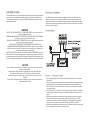
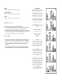
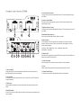
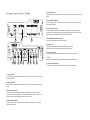
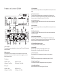
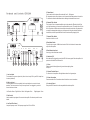
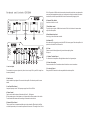
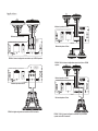
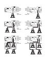
AMPLIFIER
INTRODUCTION
Mounting Guidelines
This instruction manual is for your safety and must be adhered to at all times. Please read and
ensure that you fully understand the installation and set up procedures as explained. If you
are unclear on the installation or set up of your EDGE speakers please contact your nearest
authorised EDGE dealer.
WARNING
DO NOT EXPOSE THIS PRODUCT TO DAMP OR MOISTURE - doing so may result in fire,
shock or damage to the product.
BEFORE WIRING DISCONNECT THE CABLE FROM THE POSITIVE BATTERY TERMINAL failure to do so may result in electric shock or injury.
ENSURE GOOD AND CORRECT CONNECTIONS - failure to make the correct connections
may result in fire or damage to the product.
DO NOT USE ANY FUNCTIONS OF THIS EQUIPMENT THAT MAY TAKE YOUR
CONCENTRATION AWAY FROM DRIVING YOUR VEHICLE - do not set up your amplifier
whilst driving, doing so may result in an accident. For prolonged setting up, make sure that
your vehicle is stationary and in a safe location.
KEEP THE VOLUME AT A LEVEL SO YOU CAN STILL HEAR OUTSIDE NOISE - failure to do
this may result in an accident. EDGE equipment is capable of producing sound levels that can
permanently damage your hearing. EDGE recommends caution when listening at high volume.
For safe and enjoyable listening the sound should be comfortable and clear without distortion.
Your EDGE amplifier is designed with a swift installation routine in mind. Please mount the
amplifier in a dry location on a solid surface. NEVER mount the amplifier upside down, this
will cause the amplifier to over heat and will eventually damage the amplifier. Before fixing the
amplifier in place please ensure that there is sufficient air flow around the exterior of the casing,
at least two inches is sufficient.
Connections
CAUTION
Never connect any speaker lead to the car chassis. This can cause severe damage to your
speaker /car radio /amplifier.
Before drilling or cutting any holes, investigate the layout of your vehicle thoroughly.
Use caution when working near the fuel / hydraulic lines and electrical wiring.
Observe the correct polarity when wiring, improper phasing may cause a loss of bass
response.
Ensure that no moving parts catch on the speaker or grill (e.g. window or door handles, or
window glass inside the door)
Power / Ground Cable
● The correct gauge cable should be used for both the power and the ground connections to the amplifier.
● The power cable should be taken directly from the battery. Rubber grommets should be used when passing through any bulkheads to prevent the cable from becoming chaffed or cut.
● The correct size of fuse must be fitted within 18” of the battery and before the cable passes through the bulk head
● It is vital that a fuse / circuit breaker (of at least equal value to the one fitted on the amplifier) is placed inline with the power cable and is no further than eighteen inches away from the battery.
● Please ensure that the fuse is not fitted until the entire installation procedure is complete.
● The two tables below are to help you decide on what cable is correct for you. The first enables you to select the size of cable depending on the length required. The second will help you convert the cable size from American Wire Gauge to Metric if you need to.
● The amplifier ground should be connected directly to the chassis of the vehicle, to bare metal.
● The cable length should be kept to an absolute minimum.
ED7400
● Minimum 10 AWG power / ground cable should be used
ED7800 / 71200 / 71600
● Minimum 8 AWG power / ground cable should be used
ED72500
● Minimum 4 AWG power / ground cable should be used
Remote Turn On
● A minimum of 18 gauge cable should be used for this connection.
● The cable should be run with exactly the same care and attention as the power cable and taken back to the source (headunit) and joined to the remote cable provided.
● If the source (headunit) does not have a remote turn on cable then a 12v supply should be used. This will require a switch to be fitted inline to enable the amplifier to be turned on and off. Remember that if this switch is left on you will flatten the car battery.
RCA Cables
● Depending on the model number of your amplifier and the number of speakers you wish to power you will have to run either one or two RCA cables from the source to the amplifier.
● Please take extra care when running these cables from the source to the amplifier. Ensure that they are placed away from all items that can generate any interference, wiring harnesses etc.
● It is recommended that the RCA cables should be run on opposite sides of the car to the previously installed power cables if possible, to avoid the cable picking up interference.
Limited Warranty
All EDGE goods are covered by a full 12 months
manufacturers warranty. Valid from the date of the
original receipt and proof of purchase. In order to
validate this warranty, the warranty card should be
returned to EDGE within seven days of the original
purchase date. The original receipt and packaging
should also be kept for this 12 month period.
If at any stage during the warranty period you have a
problem with the product then it should be returned
to the point of purchase in its original packaging,
complete and with no items missing.
If the store is unable to fix the product it may have
to be returned to EDGE this process takes around 7
working days.
A full description of EDGE’s warranty information
can be found on our website:
www.edgecaraudio.com/warranty
A written version can also be obtained from
EDGE warranty department
PO Box 11000
B75 7WG
Copyright
All content included in this manual such as text, graphics,
logos, icons, images data, the selection and arrangement
thereof, are the property of EDGE Audio (herein referred
to as “EDGE”, “us” or “we”) and its affiliate or their
content and technology providers, and are protected by
United Kingdom and International copyright laws. All
rights reserved.
Trademarks
EDGE ED2 , EDGE ED3 , EDGE ED4 , EDGE ED5
EDGE ED6 , EDGE ED7 , EDGE Street and
EDGE Loud and all stylised representations of
product names, or the abbreviations of product names,
as logos are all trademarks of EDGE. Graphics and
logos are trademarks or trade dress of EDGE Audio or
its subsidiaries.
TM
TM
TM
TM
TM
TM
TM
TM
EDGE’s trademarks and trade dress may not be used in
connection with any product or service that is not EDGE’s,
in any manner that is likely to cause confusion among
customers or in any manner that disparages or discredits
EDGE. All other trademarks not owned by EDGE or its
subsidiaries that appear in this manual are the property
of their respective owners, who may or may not be
affiliated with, connected to, or sponsored by EDGE or
its subsidiaries.
We reserve the right to make needed changes or
improvements to the produc and this manual , without
informing the customer about this in advance
2
3
1
5
9
4
9
Terminals and Controls ED7400
3
2
4
1
6
5
7
8
5. Low Pass Crossover Control
The control is used to select the low pass filter frequency. The frequency ranges are from 45
Hz to 300 Hz.
ED7400
2 CHANNEL AMPLIFIER 2 X 100 WATTS RMS
2 x 15 AMP
6. Crossover Control Switch
This switch is used to select high pass, low pass or flat (no crossover) operation for the
amplifier speaker outputs.
7. High Pass Crossover Control
The control is used to select the High pass filter frequency. The frequency ranges are from 45
Hz to 300Hz.
11
12
8. Bass Boost Remote Input Jack
Use to plug in the remote bass controller. (Optional ) see back
13
9. High Level Input
To be used when no RCA’s are available. Use the provided loom to connect to closest
speakers. The loom connector will only fit one way around. Once plugged in you should
connect the wires as below:
ED7400
Left Positive - White Right Positive - Grey Left Negative - White / Black
Right Negative - Grey / Black
10
9
1
2
3
6
7
4
5
8
10. Indicator LED
When the amplifier is operating correctly the LED will show as green. When the amplifier is in
protection mode the LED will show as red.
11. Power Connections
Power connections. See Connections section for details on correct connections.
1. Low Level Output
A daisy chain output For connection to another amplifier with a low level input using only a
single RCA output from the source (headunit).
2. Low Level Input
For connection to any source (headunit) with a low level output. This is your RCA output from
the source (headunit)
3. Gain Control
Used to match the input signal of the source to the amplifier. See the setup section for more
details.
4. Bass Boost Switch
To provide up to an extra +12 dB of bass boost at 45 Hz. Use this boost to increase bass output
from the amplifier.
12. Fuses
Please ensure the following fuse rating is used when replacing fuses: 15 amp x 2
13. Speaker Terminal Output
For connection to the speakers. See Application section for wiring examples.
Min
R
R
L+
R+
L-
R-
Max 35Hz 250Hz 0°
180° 16Hz 80Hz
ON
OFF
0dB
24dB
Input
1
14
3
2
4
5
6
7
9
8
5. Front Gain Control
Used to match the input signal of the source to the amplifier. See the setup section for more
details.
Terminals and Controls ED7800
ED7800
4 CHANNEL AMPLIFIER 4 X 100 WATTS RMS
6. Front Bass Boost Switch
To provide up to an extra +12 dB of bass boost at 45 Hz. Use this boost to increase bass
output from the amplifier.
2 x 25 AMP
7. Front Crossover Control
The switch is used to select between low pass / high pass filter or no filter at all on the
rear channels. The frequency ranges on the low pass filter are from 40 Hz to 300 Hz. The
frequency ranges on the high pass filter are from 40 Hz to 300hz.
10
11
8. Front Bass Boost Remote Input Jack
Use to plug in the remote bass controller. (optional)
12
9. Indicator LED
When the amplifier is operating correctly the LED will show as green
When the amplifier is in protection mode the LED will show as red.
ED7800
10. Power Connections
Power connections. See Connections section for details on correct connections.
11. Fuses
Please ensure the following fuse rating is used when replacing fuses: 25 amp x 2
9
3
2
4
1
6
5
7
8
12. Speaker Terminal Output
For connection to the speakers. See Application section for wiring examples.
.
1. Low Level Input
For connection to any source (headunit) with a low level output. This is your RCA output from
the source (headunit).
2. Rear Gain Control
Used to match the input signal of the source to the amplifier. See the setup section for more
details.
3. Rear Crossover Control
The switch is used to select between low pass / high pass filter or no filter at all on the
front channels. The frequency ranges on the low pass filter are from 40 Hz to 300 Hz. The
frequency ranges on the high pass filter are from 40 Hz to 300hz.
4. Rear Bass Boost Switch
To provide up to an extra +12 dB of bass boost at 45 Hz. Use this boost to increase bass
output from the amplifier.
L
L
R
R
Min
L+
R+
L-
R-
Max 35Hz 250Hz 0°
180° 16Hz 80Hz
ON
OFF
0dB
24dB
Input
2
1
3 5 ED71600
4
6
Terminals 9and7 Controls
3. Front Gain Control 1
3 4 5 6
14
2
9
8
7
Used to match the input signal of the source to the amplifier. See the setup section for more
details.
8
13
ED71600
4 CHANNEL AMPLIFIER 4 X 200 WATTS RMS
4. Front Crossover Control
The switch is used to select between low pass / high pass filter or no filter at all on the
front channels. The frequency ranges on the low pass filter are from 45 Hz to 300 Hz. The
frequency
rangesAMPLIFIER
on the high
filter are
from 45 Hz to 300 Hz.
4 CHANNEL
4 Xpass
100 WATTS
RMS
ED7800
3 x 35 AMP
2 x 25 AMP
5. Front Bass Boost
Switch
To provide up to an extra +12 dB of bass boost at 45 Hz. Use this boost to increase bass
output from the amplifier.
11
14 12
13
6
ED71600
7
8
10
6. Rear Gain Control
Used to match the input signal of the source to the amplifier. See the setup section for more
details.
11
10
12
7. Rear Bass Boost Switch
To provide up to an extra +12 dB of bass boost at 45 Hz. Use this boost to increase bass
output from the amplifier.
INPUT
ED7800
8. Rear Crossover Control Switch
The switch is used to select between low pass / high pass filter or no filter at all on the
rear channels. The frequency ranges on the low pass filter are from 45 Hz to 300 Hz. The
frequency ranges on the high pass filter are from 45 Hz to 300 Hz.
2
3
1
5
9
4
9. Front Bass Boost Remote Input Jack
Use to plug in the9remote
3 bass2controller.
4 (optional)
1
1. Low Level Input
For connection to any source (headunit) with a low level output. This is your RCA output from
the source (headunit).
2. High Level Input
To be
used when
no RCA’s
Use the provided loom to connect to closest
2 CHANNEL
AMPLIFIER
2 Xare
100available.
WATTS RMS
ED7400
speakers. The loom connector will only fit one way around. Once plugged
in you should
2 x 15 AMP
connect the wires as below:
Front Speakers
Left Positive - Green
Left Negative - Green / Black
Rear Speakers
11
Left Positive - White
Left Negative - White / Black
ED7400
Right Positive - Purple
Right Negative - Purple / Black
12
13
Right Positive - Grey
Left Negative - Grey / Black
6
5
7
8
10. Indicator LED
When the amplifier is operating correctly the LED will show as green.
When the amplifier is in protection mode the LED will show as red.
11. Power Connections
Power connections. See Connections section for details on correct connections.
12. Fuses
Please ensure the following fuse rating is used when replacing fuses: 35 amp x 3
13. Speaker Terminal Output
For connection to the speakers. See Application section for wiring examples.
14. Input Mode Select Switch
Allows 4 channels to be driven from a single pair of RCA leads
5. Phase Control
Can be used to alter the phase of the subwoofer from 0 - 180 degrees.
IE: the speaker output can be In phase or out of phase with the other speakers in the vehicle.
For best results rotate the dial between the two settings to determine the best sound.
Terminals and Controls ED71200
ED71200
MONOBLOCK AMPLIFIER 1 X 600 WATTS RMS
2 x 20 AMP
Power
Protect
S P-
13
10
11
SP+
SP+
7. Subsonic Filter Switch
Used to turn the filter on or off.
12
8. Bass Boost Switch
To provide up to an extra +18 dB of bass boost at 45 Hz. Use this boost to increase bass
output from the amplifier.
ED71200
Line Out
S P-
Line In
Gain
Hi Level
L
L
R
R
Min
L+
R+
L-
R-
LPF
Phase
Max 35Hz 250Hz 0°
Subsonic
180° 16Hz 80Hz
Bass
Boost
Remote
ON
OFF
9. Bass Remote Input Jack
Use to plug in the remote bass controller.
0dB
24dB
10. Indicator LED
When the amplifier is operating correctly the LED will show as greeb. When the amplifier is in
protection mode the LED will show as red.
Input
1
14
3
2
4
5
6
7
9
8
1. Low Level Input
For connection to any source (head unit) with a low level output. This is your RCA output from
4 CHANNEL AMPLIFIER 4 X 100 WATTS RMS
ED7800
the source (headunit).
2 x 25 AMP
2. High Level Input
To be used when no RCA’s are available. Use the provided loom to connect to closest
speakers. The loom connector will only fit one way around. Once plugged in you should
connect the wires as below:
Left Positive - Brown Right Positive - Black Left Negative - Blue
10
11
Right Negative - Green
12
3. Gain Control
Used to match the input signal of the source to the amplifier. See the setup section for more
details.
ED7800
4. Low Pass Filter Control
Low pass frequency control. The frequency ranges from 35 Hz to 250 Hz.
9
3
6. Subsonic Filter Control
This is used to filter out unwanted amplifier output to the subwoofer. Effectively this will filter
out all the frequencies up to the crossover point set with the control. The range is from 16 Hz to
80 Hz.Frequencies of 80 Hz and below cause the subwoofer to work hard, some subwoofers
can easily be damaged when playing very low frequencies. Using the subsonic filter allows
less distortion, delivers frequencies better suited to the subwoofer prolonging its life.
2
4
1
6
5
7
8
11. Fuses
Please ensure the following fuse rating is used when replacing fuses:
20 amp x 2
12. Speaker Terminal Output
For connection to the speakers. See Application section for wiring examples.
13. Power Connections
Power connections. See Connections section for details on correct connections.
14. Low Level Output
Daisy chain RCA connection to allow easy addition of another amplifier.
50 Hz.Frequencies of 80 Hz and below cause the subwoofer to work hard, some subwoofers
cane easily be damaged when playing very low frequencies. Using the subsonic filter allows
less distortion, delivers frequencies better suited to the subwoofer prolonging its life.
Terminals and Controls ED72500
ED72500
MONOBLOCK AMPLIFIER 1 X 1250 WATTS RMS
4 x 35 AMP
ED71200
MONOBLOCK AMPLIFIER 1 X 600 WATTS RMS
6. Subsonic
Filter Switch
2 x 20 AMP
Used to turn the filter on or off.
Power
7. Bass Boost
Procontrol
tect
To provide up to an extra +18 dB of bass boost at 45 Hz. Use this boost to increase bass
S PS PSP+
SP+
output from the amplifier.
12
8. Bass Remote Input Jack
Use to plug in the remote bass controller.
13
10
11
10
11
12
9. Indicator LED
When the amplifier is operating correctly the LED will show as green. When the amplifier is in
protection mode the LED will show as red.
ED71200
ED72500
Line Out
Line In
Gain
Hi Level
LPF
Phase
Subsonic
10. Fuses
L
Please ensure the
following Lfuse rating is used when replacing fuses:
35 amp x 4
ON OFF
Min Max 35Hz 250Hz 0° 180° 16Hz 80Hz
R
R
L+
R+
L-
R-
Bass
Boost
Remote
0dB
24dB
11. Speaker Terminal Output Input
For connection to the speakers. See Application section for wiring examples.
9
7
3
4
5
6
2
1
3 4 5 6
14 1
2
9
8
7
12. Power Connections
Power connections. See Connections section for details on correct connections.
8
13
1. Low Level Input
For connection to any source (head unit) with a low level output. This is your RCA output from
the source
(headunit).
4 CHANNEL
AMPLIFIER 4 X 200 WATTS RMS
ED71600
13. Low Level Output
Daisy chain RCA connection to allow easy addition of another amplifier.
ED7800
4 CHANNEL AMPLIFIER 4 X 100 WATTS RMS
3 x 35 AMP
2. Gain Control
Used to match the input signal of the source to the amplifier. See the setup section for more
details.
2 x 25 AMP
3. Low Pass Filter Control
Low pass frequency 11
control. The frequency
14 12 ranges from 40 Hz to 250 Hz.
13
6
7
8
10
4. Phase Control
Can be used to alter the phase of the subwoofer from 0 - 180 degrees.
ED71600
IE: the speaker
output can be Inphase or out of phase with the other speakers in the vehicle.
For best results flick between the two settings to determine the best results.
10
11
12
INPUT
ED7800
5. Subsonic Filter Control
This is used to filter out unwanted amplifier output to the subwoofer. Effectively this will filter
out all the frequencies up to the crossover point set with the control. The range is from 15 Hz to
2
1
3
5
4
9
9
3
2
4
1
6
5
7
8
Set Up Section
Troubleshooting
To correctly set the gain control of the amplifier to match that of the source (headunit) use the
following setup routine:
● Before removing the amplifier, refer to the list below and follow the suggested procedures.
● Always test the speakers and confirm that they are wired correctly first.
● If in any doubt get help from a qualified auto electrician.
Turn the gain control to minimum on the amplifier.
Ensure the bass boost is set to 0 dB.
On the headunit set all crossovers to flat and both bass and treble to zero.
Turn up the source (headunit) to approx 3/4 volume.
Very slowly turn up the gain on the amplifier until distortion can be heard in any of the speakers
or until the volume reaches an uncomfortable listening level when this is reached turn down
the gain control slightly.
The gain control is now set.
The setting of the crossover will depend on what kind of speaker you are installing.
For a subwoofer it is recommended that the crossover is set to Low Pass and the frequency is
set to match that of the speakers specifications.
For a pair of full range speakers it is recommend that the crossover is set to Flat. The two
frequency controls will then have no effect on the amplifiers output and the speaker will receive
a full range signal. However, using the high pass crossovers will allow more control of your
speakers. By removing the bass (low frequencies) the speakers can perform at higher volumes
with less distortion.
Note: The smaller the speaker, the less bass it can handle. Adjust the crossover to get the
most and best sound from your speakers. The easiest was to do this is by limiting the amount
of bass you feed them
For a pair of speakers with a passive crossover it is recommended that the crossover is set to
High Pass and the frequency is set to match that of the speakers specifications.
Note:
By using the crossovers correctly you will not only lengthen the life of your speakers but
you will also get better performance from them. To optimise your setup seek the advice of a
professional installation engineer or visit your local EDGE audio dealer.
Amplifier Will Not Power Up
● Check for good ground connections. Ensure Ground cable is connected directly to bare metal and not a painted surface.
● Using a multimeter check that remote terminal has at least 10V DC.
● Using a multi meter check that there is battery voltage on the positive terminal.
● Check all fuses.
● Check that the protection light is not illuminated. If it is lit, shut off the amplifier for thirty seconds and then turn it back on.
Protection LED Illuminates When Amplifier Is Powered Up
● Check for shorts on all speakers wires. (IE no speaker wires should be joined together and no speaker wires should be touching the cars chassis)
● The amplifier is designed to shut down automatically when the units temperature goes above 80 degrees. If the amplifier feels very hot then this may be the reason for the amplifier not starting.
● Remove the speaker wires and reset the amplifier. If the protection LED still comes on then the amplifier is faulty. This damage may have been caused by either failure to follow these setup guidelines or abuse.
Amplifier Gets Very Hot
● Check the minimum speaker impedance for the amplifier is correct.
● Check for shorts on all speakers wires. (IE no speaker wires should be joined together and no speaker wires should be touching the cars chassis)
● Check that there is good airflow around the amplifier. In some applications an external fan may be required.
Blown Fuse(s)
● Check both positive supply and ground for shorts.
● Check that the positive wire is connected to the positive terminal on the amplifier.
● Check that the negative wire is connected to the ground terminal on the amplifier.
● Ensure that the correct rated fuse is fitted
Distorted Sound
● Check the gain control is not set at too high a level. If the speakers sound distorted turn the down the gain until the sound is clear.
● Check that all crossover frequencies are correct. See setup section for more details.
● Check for shorts on all speaker wires.
● Check all speakers are wired correctly. With the correct polarity being observed on each connection.
Applications
+-
+-
+-
+-
+-
+-
+-
+-
MO
MONOBLOCK AMPLIF
Minimum impedance 2 Ohms
ED7800
4 CHANNEL AMPLIFIER 4 X 100 WATTS RMS
Power
Protect
2 x 25 AMP
ED7400
CHANNEL AMPLIFIER 2 X 100 WATTS RMS
Minimum 2impedance
2 Ohms
ED7800
4 CHANNEL AMPLIFIER 4 X 100 WATTS RMS
2 x 25 AMP
2 x 15 AMP
ED7400
2 CHANNEL AMPLIFIER 2 X 100 WATTS RMS
2 x 15 AMP
Minimum impedance 2 Ohms
ED7400 in 2 channel configuration connected to a pair of ED209 speakers
ED7400
2 CHANNEL AMPLIFIER 2 X 100 WATTS RMS
2 x 15 AMP
+-
MON
MONOBLOCK AMPLIFIE
ED7400
2 CHANNEL AMPLIFIER 2 X 100 WATTS RMS
+-
ED7800 / 71600 in 4 channel configuration connected to 2 pairs of ED209
speakers
-++
++--
+-
2 x 15 AMP
+Power
Protect
Minimum impedance 2 Ohms
ED7800
4 CHANNEL AMPLIFIER 4 X 100 WATTS RMS
Minimum impedance 4 Ohms
2 x 25 AMP
4 CHANNEL AMPLIFIER 4 X 100 WATTS RMS
ED7800
2 x 25 AMP
-
+-
Minimum impedance 4 Ohms
++ED7400 in bridged configuration connected to an ED512 subwoofer
ED7800 / 71600 in 3 channel configuration connected
to a pair of ED209
+speakers and an ED512 subwoofer
2 x 20 AMP
Power
Protect
Power
Protect
SP-
800
7800
SP-
SP+
SP-
SP+
SP+
SP+
++MONOBLOCK AMPLIFIER 1 X 600 WATTS 2RMS
x 20 AMP
2 x 20 AMP
Power
Protect
Power
Protect
SP-
SP-
SP-
SP+
SP-
SP+
SP+
SP+
Minimum
Impedance 1 Ohms
800
7800
++2 x 20 AMP
Power
Protect
SP-
SP-
SP+
SP+
+-
+-
+-
+-
71200
ED71200
MONOBLOCK AMPLIFIER 1 X 600 WATTS RMS
+
2 x 20 AMP
ED71200
ED72500
ED71200
connected in mono
configuration to an
ED512 subwoofer
at 4 ohms
SP-
SP-
SP-
SP-
SP+
SP+
ED72500
MONOBLOCK AMPLIFIER 1 X 1250 WATTS RMS
4 x 35 AMP
SP+
SP+
ED72500
connected in mono
configuration a
pair of ED512
subwoofers at 2
ohms
+-
MONOBLOCK AMPLIFIER 1 X 1250 WATTS RMS
ED72500
4 x 35 AMP
Minimum
Impedance 1 Ohms
++-
D71200
ED71200
connected in mono
configuration a
pair of ED512
subwoofers at 2
ohms
++-
ED71200
ED71200
MONOBLOCK AMPLIFIER 1 X 600 WATTS RMS
1 X 600 WATTS 2RMS
x 20 AMP
Minimum
impedance 1 Ohms
Minimum
impedance 1 Ohms
++-
-
SP-
MONOBLOCK AMPLIFIER 1 X 600 WATTS RMS
ED71200 MONOBLOCK AMPLIFIER
connected in mono
Power
Protect
Power
configuration to
an
Protect
ED512 subwoofer
at 4 ohms
++-
MONOBLOCK AMPLIFIER 1 X 600 WATTS 2RMS
x 20 AMP
++-
ED71200
ED71200
MONOBLOCK AMPLIFIER 1 X 600 WATTS RMS
+-
ED71200
connected in mono
configuration to 4
ED512 subwoofers
at 1 ohms
ED72500
connected in mono
configuration to 4
ED512 subwoofers
at 1 ohms
Minimum
Impedance 1 Ohms
Minimum
Impedance 1 Ohms
+-
MONOBLOCK AMPLIFIER 1 X 1250 WATTS RMS
ED72500
4 x 35 AMP
+-
+-
+-
+-