1
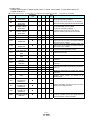
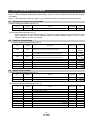
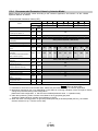
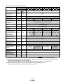
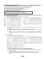
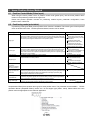
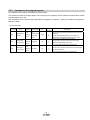
4.4 Torque control mode
(1) [Extension setting parameters (No. PC□□)]
No.
Symbol
Name
Default
Unit
PC01
STA
Acceleration time constant
0
ms
PC02
STB
Deceleration time constant
0
ms
PC05
SC0
Internal speed limit 0
0
r/min
PC06
SC1
Internal speed limit 1
100
r/min
PC07
SC2
Internal speed limit 2
500
r/min
PC08
SC3
Internal speed limit 3
1000
r/min
PC31
SC4
Internal speed limit 4
[Applied]
200
r/min
PC32
SC5
Internal speed limit 5
[Applied]
300
r/min
PC33
SC6
Internal speed limit 6
[Applied]
500
r/min
PC34
SC7
Internal speed limit 7
[Applied]
800
r/min
Initial value
Unit
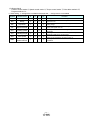
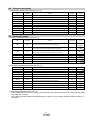
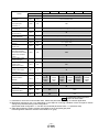
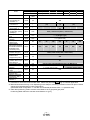
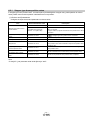
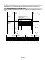
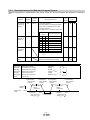
4.5 Positioning mode
(1) [Basic settings parameters (No.PA□□)]
No.
Symbol
PA05
FBP
PA06
CMX
PA07
CDV
Name
Number of command input pulses per revolution
Electronic gear numerator
100
×100
pulse/rev
1
(Command input pulse multiplying factor numerator)
Electronic gear denominator
1
(Command input pulse multiplying factor denominator)
PA08
ATU
Auto tuning mode
PA09
RSP
Auto tuning response
PA10
INP
In-position range
100
PA13
PLSS
Command input pulse form
000h
PA14
POL
Rotation direction selection
0
001h
6
pulse
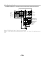
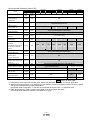
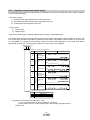
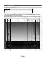
(2) [Positioning setting parameters (No. PE□□)]
No.
Symbol
Name
PE01
CTY
Command mode selection
0000h
PE02
FTY
Feeding function selection
0000h
PE03
ZTY
Home position return type
0010h
PE04
ZRF
Home position return speed
500
r/min
PE06
ZST
Home position shift distance
0
μm
100
ms
Home position return/JOG operation
Initial value
Unit
PE07
FTS
PE08
ZPS
Home position return position data
PE13
JOG
JOG speed
PE16
LMPL
Software limit +
0
×10
STM
PE18
LMNL
Software limit -
0
×10
STM
Accelerationeration/Deceleration time constants
0
100
×10
STM
μm
r/min
μm
μm
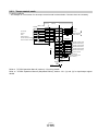
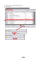
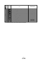
(3) [I/O setting parameters (No. PD□□)]
These parameters are set when changing the assignment of the input/output signal and using the point table
at a maximum of 7 points.
See “LECSA Operation Manual (Simplified Edition)”,section 5.5 and “LECSA Operation Manual”,section 4.4
for details.
- 17 -