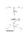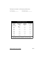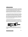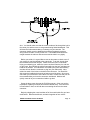
1
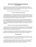
D IP N OL E ANTEN Ramsey Electronics A DA-160 Looking for an easy to build, solid performing antenna? The dipole is hard to beat! These inexpensive, high quality antennas are the time tested solution to price, relative invisibility, and most of all, performance. • User tested, proven antenna technology to bring you the best value. • Clear, concise instructions are just what you won’t find with other antennas. Our manual teaches you everything that you need to know, and even points you in the right direction if you want to learn more! • Can be set up as a typical dipole antenna, or the popular “Inverted V” configuration, for less space and excellent performance. • Build a home brew antenna... right down to the last soldering connection. • These dipoles are virtually invisible, but do not compromise performance, or signal capabilities. • Perfect as a second antenna for those whose antennas won’t handle a specific band. • High quality components assure you a working antenna every time... and tuning it is so easy! • The right antenna at the right price. RAMSEY DA SERIES DIPOLE ANTENNA Page 1 PARTIAL LIST OF AVAILABLE KITS RAMSEY TRANSMITTER KITS • FM-10 FM Stereo Transmitter • FM-1,2,4 FM Wireless Microphones • PB-1 Telephone Transmitter • AM-1 AM Transmitter RAMSEY RECEIVER KITS • FR-1 FM Broadcast Receiver • AR-1 Aircraft Band Receiver • SR-1 Shortwave Receiver • AA-7 Active Antenna • SC-1 Shortwave Converter RAMSEY HOBBY KITS • SG-7 Personal Speed Radar • SS-7 Speech Scrambler • MM-5 Digital Music Maker Machine • SP-1 Speakerphone • MD-3 Microwave Motion Detector • PH-10 Peak hold Meter • LC-1 Inductance-Capacitance Meter RAMSEY AMATEUR RADIO KITS • FX Series VHF and UHF Transceivers • HR Series HF All Mode Receivers • QRP Series HF CW Transmitters • CW-7 CW Keyer • PA Series VHF and UHF Power Amplifiers • Packet Computer Interfaces • QRP Power Amplifiers RAMSEY MINI-KITS Many other kits are available for hobby, school, scouts and just plain FUN. New kits are always under development. Write or call for our free Ramsey catalog. DP-1 DIPOLE ANTENNA INSTRUCTION MANUAL Ramsey Electronics publication No. MDA-1 Revision 1.0 First printing: August, 1994 COPYRIGHT 1994 by Ramsey Electronics, Inc. 793 Canning Parkway, Victor, New York 14564. All rights reserved. No portion of this publication may be copied or duplicated without the written permission of Ramsey Electronics, Inc. Printed in the United States of America. Page 2 RAMSEY DA SERIES DIPOLE ANTENNA Ramsey Publication No. DA Manual Price Only: $5.00 ASSEMBLY AND INSTRUCTION MANUAL FOR DIPOLE ANTENNA KIT TABLE OF CONTENTS Introduction ......................................................... 4 Antenna Description............................................ 4 How Does a Dipole Antenna Work? ................... 6 Schematic Diagram............................................. 7 Parts List ............................................................. 8 What Kind Of An Antenna Is Best For You? ....... 9 Construction Notes ............................................. 10 Antenna Construction ......................................... 13 Tuning Your Antenna .......................................... 15 Other Reading..................................................... 15 RAMSEY ELECTRONICS, INC. 793 Canning Parkway Victor, New York 14564 Phone (716) 924-4560 Fax (716) 924-4555 RAMSEY DA SERIES DIPOLE ANTENNA Page 3 INTRODUCTION Welcome to your new dipole antenna. Dipole antennas are an extremely popular form of antenna today, because they satisfy the demands of almost any application! There are not many antenna designs that are so low cost, simple and “invisible”. You may not know that they are also exceptionally good radiators, beating many other antennas hands down. Their exceptional qualities on low frequency bands such as 160, 80 and 40 meters is also a great advantage over antennas many times their price. As you may know, living in a neighborhood with other people may immediately lead to problems with neighbors who are worried about the effect that your antenna will have on them. Many people are worried about your ham gear interfering with their television sets or radios. In addition, many people who simply don’t know enough about your hobby may think that it could attract lightning to their houses, or even fall off of your roof (heaven forbid!) This is where the “invisible” properties of a dipole are so important. In a short day’s work, you can install your antenna that to even the nosiest neighbor might be strained to see. But the great thing is that your antenna is also a great radiator. Is it any wonder why hams who spend over a thousand dollars on beam antennas for 20, 15 and 10 meters also own dipoles to work the 160, 80 and 40 meter bands? In fact, dipoles are one of the oldest, and most tested antennas in existence. This is why we are proud to offer you a reliable, time tested antenna design at low cost. ANTENNA DESCRIPTION Your Ramsey antenna has been designed for practicality, performance and price. Every effort has been made to offer you not only high quality parts, but also an affordable price that will make beginners starting in the hobby, or avid hams looking for a second antenna feel good. Because we offer a range of antennas, each designed for a different band, you will notice that this book encompasses each of them. In the tables provided, use the data that best resembles your particular purpose and needs. Page 4 RAMSEY DA SERIES DIPOLE ANTENNA HOW DOES A DIPOLE ANTENNA WORK? A dipole antenna is a long wire that is suspended between two points. The wire is cut to a specific length, and is fed in the middle with a radio frequency (RF) signal. One half of the antenna is hooked to the ground wire of the transmission line, and the other is hooked to the center conductor. As an RF signal is applied to a piece of wire, both an electric and a magnetic field is set up around the wire. These waves propagate through the air (or ether!) without limit. As these magnetic and electric fields reach another station’s antenna (or about any other metal object in it’s path) the exact reverse effect takes place on our antenna that our RF signal did. The rapidly changing fields produce an RF current that your receiver can detect. Although it is impossible to actually see the waves coming off of a dipole, we can try to visualize it to understand it better. Take a piece of paper and push a pen or pencil through the center. Hold it up in front of you. Let’s pretend that the pencil represents our antenna, and the paper represents where our signal is concentrated. As you can see, most of the radiation is given off at a 90 degree angle to the antenna, with very little radiation occurring parallel to the pencil. It is this property that makes the dipole directional. Another advantage is that the radiation is at all angles around the wire, and the signal has a maximum chance to skip through the atmosphere, making the dipole ideal for DX. An inverted dipole does have a number of advantages over typical dipoles. For one thing, they take up less space, with some of their wire being used up to climb a vertical distance, and a five percent reduction in antenna length over a normal dipole. They also match their impedance more easily to a 50 ohm coaxial cable than a typical dipole, which has an impedance of 65 ohms. The inverted dipole also has a higher angle of radiation — making it better for sky wave DX. If you have any questions, we suggest that you look for the ARRL Handbook, which has all sorts of great information for hanging antennas. RAMSEY DA SERIES DIPOLE ANTENNA Page 5 PARTS LIST 3 End Insulators Length of Coaxial Feedline Cable Length of Rope 1 PL-259 Connector 1 UG-175/U Reducer Length of Antenna Wire 2 Wire Cable Ties REQUIRED, NOT SUPPLIED Some Good Friends (Suckers) Soldering Iron Gun with Rosin Core Solder Waterproof Sealant (Silicone) and Electrical Tape Radio Transmitter Sharp Knife Wire Cutters WHAT KIND OF ANTENNA IS BEST FOR YOU? Unlike many antennas that you can find on the market, the Ramsey dipole antenna is capable on being constructed in two configurations. These are, a normal dipole, and an “Inverted V” antenna. A normal dipole is just what we have been talking about. An Inverted V is a variation of a normal dipole that features slanting wires for easier mounting on small properties, or where you wish to mount the center of your antenna high without having to build two high endpoints (see diagram on next page). Antenna critics agree that there is little difference in performance between the two antennas. One difference between the two types of antennas is the wire length. Because of slightly different antenna characteristics, the Inverted V antenna is slightly shorter. This has to do with a number of physical factors such as end effect (the magnetic and electric fields at the end of the wire), and the proximity and angle to the ground. To accommodate this difference in Page 6 RAMSEY DA SERIES DIPOLE ANTENNA RAMSEY DA SERIES DIPOLE ANTENNA Page 7 length, we have included a bit more wire than you should need to build either antenna. This allows you to decide which antenna will serve you better. CONSTRUCTION NOTES Just a few notes before you begin constructing your antenna. • Be careful when constructing your antenna! Throwing rocks through windows, falling from trees, shooting a buddy during the famous bow and arrow trick and becoming electrocuted are just a few of the hazards that can ruin your day. • If the weather looks threatening, wait for it to pass. The last thing that you want is to be caught on your roof during a storm. • Don’t take chances with your antenna. Secure it as well as you can, and make sure that nobody will be able to touch it once it is mounted. Transmitting while someone is touching it can be a shocking experience. • When in doubt, have your buddies help you out! A few friends can make the day a lot more enjoyable and easier... especially if they know a thing or two about stringing antennas (or own a bow or arrow). ANTENNA CONSTRUCTION Now it’s time to begin construction! First, make sure that you have all of your antenna parts, and they are easily accessible. You’ll also need tools such as; ladders, electrical tape, waterproof sealant, a knife, wire cutters, etc. The first thing to do is to cut the antenna wire to the correct length. The wire supplied with your kit has been cut somewhat longer than required, but there is not enough for two antennas, so be careful when you measure! The following table shows you the proper lengths to cut your antenna wires in order to tune it to the proper frequency. Please understand that the calculations that we have made are for a frequency in the center of the band. If you prefer to use another frequency, or a band that is not listed, simply find the lengths by using the following equations. (It doesn’t hurt to add a foot or so to the calculated length to allow for easier antenna tuning - it’s easier to simply “clip” off a bit of wire at a time than it is to add wire.) Total length of a dipole = 468/ frequency (in MHz) (in feet) Page 8 RAMSEY DA SERIES DIPOLE ANTENNA Total length or an Inverted V = 445/ frequency (in MHz) (in feet) Your Frequency_________ Calculated Length___________ Antenna Wire Length (per side) ANTENNA BAND FREQUENCY (KHz) NORMAL DIPOLE INVERTED V ALL BAND > 1850 129’3” 122’9” 160m 1850 129’3” 122’9” 80m 3750 63’9” 60’6” 40m 7050 33’11” 31’6” 20m 14250 16’9” 15’8” 10m 28500 8’5” 7’11” NOTE: Measurements indicated for each side of dipole. RAMSEY DA SERIES DIPOLE ANTENNA Page 9 For example, to make a dipole antenna on 14.050 MHz, divide 468 by 14.05. The total dipole length be 33.31 feet or approximately 33 ‘4”. Don’t forget that you need to insert a feedline in the center, so it must be cut into two pieces that are one half the length (16 feet, eight inches). Wire Length (approximate length packed with indicated antenna kit) 160m or ALL BAND .................. 262’ 80m ............................................ 132’ 40m ............................................. 72’ 20m ............................................. 38’ 10m ............................................. 21’ Page 10 RAMSEY DA SERIES DIPOLE ANTENNA ASSEMBLING THE ANTENNA Start by finding three locations to attach your antenna. The center location must be close enough to your ham shack so that the coaxial cable will reach, but should also be as high as possible. Attaching it to a location on the roof, or to the chimney is a great place, as long as you are sure that the wires will not come into contact with trees, power lines (cringe!) or the house. Remember what that great ham, W2BOZO said, “If you touch a powerline with that antenna, you’re going to be one sad ham.” Kind of says is all, huh? Remember, the antenna wire is not insulated (and does not need to be). The two end locations should also be sufficient so that the antenna stays somewhat straight, and is a safe distance off of the ground. You should also make sure that they are sturdy enough. Ripping the aluminum drain piping off of the side of your house, or pulling your favorite night table out of your bedroom window by one of the legs not only earns you bad points with the spouse, but it can get expensive and dangerous quickly. The best items for this? A sturdy metal pole, tall fence pole, good sized tree, sturdy connection point on your house or garage, and almost any place that you can trust to hold the antenna under windy conditions. When you have found these spots, it is time to prepare the antenna. First, take one end of each of the wires, and place them on your workbench, or other suitable area with a high power soldering gun. Next, place one of the insulators in front of you on the table. Some manufacturers and ham radio dealers sell center insulators that have various mounting features. If you see one that you feel would be well suited for this job, you may substitute it for the center insulator. Be aware, however, that many of them can be considerably more expensive to perform the same job as the one that you now have. RAMSEY DA SERIES DIPOLE ANTENNA Page 11 Taking the end of one of the wires, pass it through the hole in the insulator until six inches are through. Next, bend the wire back on itself and immediately begin to wrap it very snugly and neatly around itself. Ideally, you should have about six or seven turns. Using your soldering iron, heat up the wire turns and solder each of them until the wire is secured very tightly. This way, the loops take up most of the stress, but the solder keeps it from getting loose. Connect the other wire in the same manner. Make sure that you look over each connection thoroughly. Next, take the remaining two insulators and connect the wire to them using almost the same method. Pull 18 inches through the hole before securing it. Don’t forget to leave a 1 inch loop! The extra wire allows you to trim the wire easily, while the extra wire acts as part of the antenna length. Six inches are used up at each end of the wire to secure it, and the other foot is used here to hang down for easy tuning. Now it is time to connect your PL-259 connector to your coaxial cable. This is the end that will be connected to your radio. Unscrew the large outer shell from the PL-259 connector and place it onto the coaxial cable with the threaded end (inside) facing the end of the wire that you are working on. Next, place the UG-175/U reducer onto the coax cable with the thinner end towards the end of the cable. Using a sharp hobby knife, carefully strip the outer insulation off of the coax cable by cutting all of the way around the wire, one inch from the end. Under this insulation is a thin layer of braided wire. Be careful not to cut these wires. Once the insulation is gone, move the UG-175/U reducer up the wire until it’s end is flush with the spot where the insulation has been taken off. Gently spread the braid at the top and then fold it back over the UG-175/U reducer. Using your knife, strip the insulation off of the center conductor 1/4 inch past where you stripped the outer insulation. Be careful not to cut the conductor itself, or you will have to cut down the wire and go through the whole process again. Twist the wires of the center conductor together and tin them. You should now trim the outer wire braid at the point where the threads begin on the UG-175/U reducer. This will keep them from fouling up the screw threads. Carefully place the remaining piece of the connector over the end of the Page 12 RAMSEY DA SERIES DIPOLE ANTENNA wire. You should make sure that the center conductor fits through the hole in the center pin, and there are no stray strands being folded backwards. This will have the unfortunate tendency of shorting out your antenna. The connector should cover the braided wire and trap it against the reducer. Snug it down so that it is firmly on the wire. The braided shield should be caught between the reducer and connector and be held in very tightly. Before you solder, it is a good idea to use an ohmmeter to check to see if your center pin may be shorted to the outer braid. To do this, simply place the ohmmeter across the two pins. Infinite ohms and you’re in the clear! Using your soldering gun, solder the center conductor onto the pin, and trim off any extra. Be sure that the solder flows easily into the hole, and does not bead on the outside. This indicates a cold solder joint (more heat needed), and also will not allow the connector to plug into your radio easily. Next, solder into each of the holes on the side of the connector. You should be able to see the braided wire through at least some of the holes. Once more, check with your ohmmeter to see if there is a short. Please note that it is not recommended that you leave the connector unsoldered. Moisture will quickly cause all of your connections inside to go bad. Screw the large outer ring onto the PL-259 connector. (Now you see the importance of placing it onto the wire with the threads out!) Your connector is now finished. Next, we will talk about connecting the wire to the center connector. Begin by stripping the outer insulation off of the coaxial cable like you have done before. Bend the braid back, and twist it together to form a thick RAMSEY DA SERIES DIPOLE ANTENNA Page 13 stranded lead about one inch long. Next, strip the center conductor 1/4 inch closer to the end. Tin both leads. Wrap the coax wire around the center insulator making sure that it is snug in one of the two grooves. The end of the coax should loop around and fold back on itself, overlapping about one inch. Fasten the coax to itself using the nylon wire ties supplied. You should still have a short length of wire coming from each antenna wire connection. Connect one of these to the center conductor, and one to the outside conductor of the coax. Be sure to solder them well. If the wires have a lot of slack in them, you may want to cut off some excess wire and then connect them. The solder connections should not support any weight, if possible. This will help their longevity. You should now add waterproof sealant such as silicone caulking (Silastic, RTV). After you have done this, seal it further using electrical tape. After you have ensured that the coaxial cable is snugly attached, it is time to mount your antenna. First, identify where you would like the center of your antenna (as a general rule, the higher the better). Although it is better to find a place where you can secure it, you may also suspend it using the strength of the ends to hold it in the air. If you need to secure the antenna, tie a length of rope to the object that you are securing it to. Next, tie the rope to the center insulator very tightly (short of breaking it, please!). If you have some patience, the rope will fit between the fins of the insulator, and will secure itself very nicely. We suggest that you use a knot that will not loosen with time. (A Boy Scout may be handy for tying knots and climbing trees.) Once the center is at the proper location, make sure that your coaxial cable will easily reach your radio. Next, stretch out one of the wires and bring the end up to where you wish to secure it. If the location is difficult to reach easily, you may wish to consider securing it to a lower spot until after you have finished tuning it up. Using more rope, tie one end to the object, and one end to the hole in the free end of the insulator. Again, use knots that will not come loose with time. If you think that the object that you are tying your antenna to is going to move due to winds or other factors, you may wish to consider using a pulley or similar system of compensating for this. Connect the other end of the dipole in the same fashion. Be sure that the dipole does not sag too much, but also be aware that tightening it up too much may put undue strain on it. Page 14 RAMSEY DA SERIES DIPOLE ANTENNA TUNING YOUR ANTENNA Hook up your radio to an SWR meter and the antenna. Set it for a portion of the band that you think you will be using most often. Since all of our antenna length calculations are for the center of the band, the antenna should be slightly longer if you wish to work below this frequency, and slightly shorter if you work above it. Reduce your power down to it’s lowest setting and transmit on a clear frequency. Your SWR meter should now be measuring the SWR of your antenna. You will notice that if you tune up or down, this will change. Try this, and note whether or not the SWR gets higher or lower as you go up in frequency. If it gets higher as you go up, the antenna needs to be shortened. Back outside again (or get a buddy to stand out there), cut about one inch off of each end of the antenna wire. Rekey your transmitter and repeat the same test over. If the antenna still needs to be shortened, cut off a bit more. Over and over, perform this test until the frequency that you wish to tune the antenna at has a lower SWR than the frequencies above or below it. Now that your antenna has been successfully tuned, you are ready to try making a few contacts. RAMSEY DA SERIES DIPOLE ANTENNA Page 15 DA DIPOLE ANTENNA Quick Reference Page Guide Introduction ......................................................... 4 Antenna Description ........................................... 4 How Does a Dipole Antenna Work? ................... 6 Schematic Diagram ............................................ 7 Parts List ............................................................. 8 What Kind Of An Antenna Is Best For You? ....... 9 Construction Notes ............................................. 10 Antenna Construction ......................................... 13 Tuning Your Antenna .......................................... 15 Other Reading .................................................... 15 Manual only price: $5.00 Ramsey Publication No. MDA Assembly and Instruction manual for: RAMSEY DA SERIES DIPOLE ANTENNA RAMSEY ELECTRONICS, INC. 793 Canning Parkway Victor, New York 14564 Phone (716) 924-4560 Fax (716) 924-4555 Page 16 RAMSEY DA SERIES DIPOLE ANTENNA Printed on Recycled Paper