1
v
• • • • .alll
..
Model CD-400B
CD-4
Disc Demodulator
--~
MARANTZ CO;, INC.· P.O. BOX 99· SUN VALLEY, CALIFORNIA· 91352
A WHOLLY-OWNED SUBSIDIARY OF SUPERSCOPE INC., SUN VALLEY, CALIFORNIA 91352
'WARRANTY'
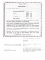
'Marantz: Company. Inc., proudly warrants YO!-" Ma...ntt product to .befree ofmanufaeturing defects
inmateriafand workman,ship as follows:
.
From .date, of purchase .
PARTS· 3
.
.
Electronic Components and. Receivers
.LA" BO'R" _
years
Syears
" PARTS" 3 years
·...eadphones
LABOR, 3years
PARTS. 3 years
4-Channld- Remote Control
LABOA- . 3 '1ears
PARTS'· 3 years
P1ug~in Matrix Dec:oders ...
LABOR' - 3 years
PARTS· 5 years
SpeakQfS afld Cabinets
LABOR - 5 years
TO VALIDATE YOUR WARRANTY; YOU MUST Fill OUT AND MAIL THE WARRANTY REG
ISTRATION CARD TO MARANTZ COMPANY. INC.~ P. O.BOX 99, SUN VALLEY, CALIFORNIA
91352, WITHIN TEN DAYS FOllOWING THE DATE OF PURCHASE.
F()r' Warranty repair, send this produ.ct,to Marantz COmpa"y, lnt:, 8150 Vineland Avenue, Sun Valley,
Cillifornia 91352,01' to an AUTHORIZED. Matantz Service Station. AllShipping charges must be prepaid.
.
Marantz·will pay returrishtpPlngehatges toanydeilignatedpoint within the United States.
This VVarranty is void if the serial number has been altered or removed; if the prowctk modified or
repaired in any manne{ whicb Marantz believes may affect the reliabitityof the product; if the product
is not OPerated in accordance witll theinstruetion manual,
Marantz shall ha'le no liability whatsoever for consequential damages. The sole responsibility of Marantz
Company, Inc., under this Warranty shall be linlited to the repair of the product. or replacement ther.eof,
in the sole discretion of Marantz C()mpariy. InC.
EXCEPT TOTHE EXTENT THATAPPLICABLE LAW t'RECllJOES A DISCLAIMER OF WARRANTY,
THERE IS NO IMPLIED WARRANTY OF MERCHANTABILITY OR FITNESS WITH REsPECT .TO
THIS PRODUCT. NOR ARE THERE ANY OTHER WARRANTIES WHICH EXTENT BEYOND'
THE PROVISIONS OFTHISWARRAN'tY. .
.
8150 Vineland Avenue, Sun. Valley, Calijor'nia 91352'
REGISTRATION FOR MARANTZ 3-YEAR GOLDEN
WARRANTY
Model Purchased
Date of Purchase _..--_
Place of Purchase
Address
Serial Number
AC Line Operation
WARNING: TO PREVENT FIRE OR SHOCK HAZARD, 00
NOT EXPOSE THIS APPLIANCE TO RAIN OR MOISTURE.
City _
_ State
_
~
The above information becomes your permanent record of
a valuable purchase. It should be promptly filled in at the
same time that you fill in and mail the warranty registration
reply card to Marantz. This information provides a valuable
insurance record and must also be referred to should you
have any correspondence with Marafitz.
I
FOR WORD
To obtain optimum performance and enjoyment
from the Model CD-400B, please study these in
structions and follow the step-by-step procedures
carefully.
This manual is divided into two parts. The first
covers installation and operation in simple, non
technical language. The second describes the
Model CD-400B in more technical detail.
For quick identification of the controls and con
nections, references to these are printed in BOLD
FACE TYPE.
GENERA DESCRIP 10
Your Marantz Model CD-400B is a simple to
operate demodulator for obtaining four discrete
channels from CD-4 records. The Model CD-400B
incorporates an Automatic Noise Reduction Cir
cuit to minimize record noise without affecting
frequency response, and an automatic 30 kHz
carrier level control which selects the optimum
carrier level for the cartridge being used. NoncCD
4 records may also be played through the CD
400B without affecting their performance. The
CD·400B's controls do not have to be adjusted to
play non-CD-4 records. When CD·4 records are
played and the MODE pushswitch is in the
4 CH AUTO position, the RADAR indicator will
illuminate and the record will automatically be
demodulated into four discrete channels.
AFTER UNPACKIN
It is advisable to retain all original packing ma
terial to prevent damage should' you wish to
transport or ship the Demodulator (refer to page
8 for repacking and shipping instructions),
Please'inspect your CD-400B carefully for any
signs of shipping damage. Our very strict quality
control and professional pride ensure that each
CD-400B left the factory in perfect condition. If
the unit is damaged or fails to operate, im
mediately notify your dealer. If the unit was
shipped to you directly, notify the transportation
company with'out delay. Only you, the consignee,
may institute a claim against the carrier for
shipping damage. Save the carton and all packing
material as evidence of damage for their inspec
tion. Should assistance be required, the Marantz
Company will cooperate fully in assisting your
claim.,
Please fill out and mail the Warranty Registration
Card as soon as possible. The Marantz 3-year
Golden Warranty will not go into effect until the
Marantz Company receives the registration card,
which was packed in the carton with your Model
CD-400B.
TABLE 0 C NTENTS
Connecting the CD-400B
Adjustments
2
2
Front Panei Features
Power Indicator
Power Switch
Selector Switch
Mode Switch
4
Rear Panel Features
2 CH Direct Out Switch and Jacks
Phono Input Jacks
Aux Input Jacks
4 CH Out Jacks
Chassis Ground
Separation Controls
Line Cord
5
5
5
5
5
5
5
5
Operation Notes
6
Functional Description
6
General Specifications
8
Service Notes
Repairs
8
8
4
4
4
4
LIST FilL S RATIONS
1. Connection Diagram
2. Front Panel Switches
3. Rear Panel Connection
Facilities and Controls
4. Cartridge Mounting
5. Functional Block Diagram
6. Packing Instructions
3
4
5
6
7
8
CONNECTING T E C. -4008
Turn off the Model CD-400B and any equipment
that will be connected to it before making any
connections. The CD-400B must be used with a
turntable or changer equipped with a cartridge
designed for CD-4 records.
4. Set the controls on the 4-channel amplifier in
accordance with the manufacturer's instruc
tions.
5. Set the CD-400B's front panel MODE push
switch to the 4 CH AUTO position.
6. Set the front panel SELECTOR pushswitch to
the PHONO position.
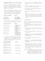
1. Connect the turntable or changer to the rear
panel of the CD-400B with the special audio
cables recommended by the cartridge manu
facturer. Using any other cable may seriously
degrade the performance of the CD·400B.
TURNTABLE/CHANGER
CD-400B
LEFT OUTPUT
RIGHT OUTPUT
GROUNDING WIRE
to lEFT PHONO
to RIGHT PHONO
to CHASSIS GROUND
7. Set the rear panel DIRECT OUT switch to
OFF.
8. Connect the AC line cord to an AC outlet
providing the AC voltage and frequency speci
fied on the rear panel serial number nameplate.
Turn on the turntable, CD-40GB and 4-channel
amplifier.
ADJUSTMENTS
2. Using standard shielded audio cables with
phono plugs make the following connections.
4·CHANNEL AMPLIFIER
CD·400B
FRONT CD·4/AUX L
to 4 CHANNEL OUT
FRONT l
to 4 CHANNel OUT
FRONT R
to 4 CHANNEL OUT
REAR L
to 4 CHANNel OUT
REAR R
to 2 CHANNEl DI
RECT OUT lEFT
to 2 CHANNEL 01·
RECT OUTRJGHT
FRONT CD-4/AUX R
REAR CD-4/AUX L
REAR CD·4/AUX R
PHONO IN LEFT
PHONO IN RIGHT
3. A discrete 4-channel playback device (0-8
cartridge player, 4-channel discrete reel-to-reel
tape deck, etc.) may be connected to the CD
400B using standard shielded audio cables with
phono plugs as follows:
DISCRETE 4-CHANN.El
PLAYBACK DEVICE
CD-400B
LEFT FRONT or L F or
CHANNEL 1 or TRACK 1
to FRONT AUX l
LEFT REAR or L R or
CHANNEL 2 or TRACK 2
to REAR AUX l
RIGHT FRONT or R For
CHANNEL 3 orTRACK 3
tp FRONT AUX R
RIGHT REAR or R R or
CHANNEL 4 orTRACK 4
to REAR AUX R
Before the Model CD·400B can properly demod
ulate CD-4 records, a few simple adjustments
must be made.
The following adjustment procedure should be
performed whenever a new cartridge or stylus is
installed.
1. Decrease the front channel volume on the '....t
main amplifier so that only the rear speakers
can be heard.
2. Play the CD-4 ADJUSTMENT TONE band of
the test record.
3. Adjust the rear panel
LEFT SEPARATION
CONTROL for minimum sound level from the
left rear speaker.
4. Play the CD-4 ADJUSTMENT TONE band of
the test record.
5. Adjust the rear panel RIGHT SEPARATION
CONTROL for minimum sound from the right
rear speaker.
6. PlaytheCHANNELBALANCE ADJUSTMENT
TONE band of the test record and using the
BALANCE CONTROLS of the main amplifier,
adjust the relative sound level of each of the
four channels to achieve a satisfactory four
channel balance.
NOTE: The CD-400B contains a special circuit
to control the lock range of the carrier
detector and thereby optimize its per·
formance. No adjustments for carrier
level (band 2 of the supplied test record)
-.t -
are therefore necessary. However, in
extreme cases of badly worn discs and
stylus or poorly designed cartridges, the
carrier level output may be outside the
range of automatic compensation, caus-
ingdistorted sound and intermittent
4-channel operation. If this is the case,
either. a new disc, a new stylus, or a
better cartridge must be secured.
MARANTZ MODEL CD-400B
OUTPUT
. OUTl'ItT
00
1--------- I"~ 0
U
'-----------'
FRO"T LEfT
©
FRO"T RIGHT@
REAR LEFT
REAR RIGHT
©
.
©
CD·4 RECORD PLAYER
4·CHANNEL
TAPE DECK
4·CHANNU AMPLIFIER
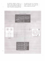
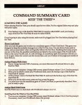
Figure 2. Front Panel Switches
FRONT PANEL FEATURES'
crete 4-channel sources such as an 8-track tape
deck, 4-channel reel-to-reel deck, etc.
MODE SWITCH
POWER INDICATOR
The POWER INDICATOR illuminates to signify
that the Model CD-400B is on when the POWER
pushswitch is depressed.
POWER SWITCH
The POWER pushswitch activates the Model
CO·400B's power when depressed. When the push
switch is released, the AC power is off.
SELECTOR SWITCH
When this switch is set to the PHONO position,
the Model CO-400B is set for listening to CO-4,
2-channel, or 4,channel matrix records.
When set to the AUX position, any input that
has been connected to the rear panel AUX input
jacks will be fed directly through the CO-400B's
4 CH OUT jacks. This permits listening to dis-
4 CH AUTO: When in the 4 CHAUTO position,
CO-4 records will automatically be reproduced
with four discrete channels. 2-channel records
and 4-channel matrix records will be reproduced
with the left channel of the record fed to the
left front and left rear amps, while the right
channel is fed to the right front and right rear
amps..
. 2CH: When in the 2 CH POSItIon all records,
including CO-4 records, will be reproduced in
the 2-chimnel mode. Some 2-channet records
may contain enough high frequency signals to
. render them unplayable in the 4 CH AUTO posi
tion.lf this occurs, set the MODE switch to the
2 CH position.
RADAR: When the MODE pushswitch is set to
the 4 CH AUTO position, the RADAR indicator
will illuminate when a COA record is being played.
Figure 3. Rear Panel Connection Facilities and Controls
4 CH OUT JAC KS
2 CH 01 RECT OUT SWITCH AND JACKS
When set to the ON position, the PHONO INPUT
signal is fed directly to the DIRECT OUT jacks.
These jacks may be connected to the PHONO IN
jacks of an amplifier as an alternate method for
playing stereo or 4-channel matrix records. When
set to the OFF position, the PHONO INPUT
signal is processed by the CD-400B.
These high level output jacks should be connected
to the AUX IN or CD-4/AUXjacks on a 4-channel
console amplifier or pre-amplifer.
CHASSIS GROUND
This binding post is for the connection of the
ground wire from the turntable or record changer.
PHONO INPUT JACKS
SEPARATION CONTROLS
These jacks are intended to be used with a CD-4
magnetic cartridge.
The LEFT and RIGHT SEPARATION CON
TROLS adjust channel separation between the
left front and left rear and right front and right
rear speakers respectively. See adjustment section.
AUX INPUT JACKS
These jacks are for connecting any 4-channel high
level source. Manufacturers may use different
terminology for the four channels, and care
should be exercised to avoid confusing the chan
nel connections. The following are examples of
4·channel nomenclature equivalents:
:JI LEFT FRONT
LEFT REAR
RIGHT FRONT
RIGHT REAR
LINE CORD
Connect the AC line cord to an AC outlet provid
ing the AC voltage and frequency specified on the
rear panel serial number nameplate.
LF-LF- CHANNEL 1 -TRACK 1
LR-LB- CHANNEL 2 -TRACK 2
RF-RF- CHANNEL 3 -TRACK 3
RR-RB- CHANNEL 4 -TRACK 4
5
OPERATION NOTES
,FUNCTIONAL QESCRIPTION
1. Separation Adjustment
Once the separation controls are set they
should not need readjustment until the car
tridge and/or stylus is replaced.
2. Anti-Skating
For optimum results with the CD-400B, the
anti-skating force on the turntable should be
carefully adjusted in, accordance with the
manufacturer's instructions.
3. Cartridges
Only a magnetic cartridge designed for CD-4
reproduction will provide usable playback re
sults. The cartridge must be mounted per
pendicularto the record surface. See Figure 4. '
The stylus must be kept clean. Consult your
dealer for cleaning accessories.
4. Turntable Leads
Only coaxial audio cables designed for CD-4
use should be used. Consult your dealer for the
proper type.
5. TV Interference
A TV set located near the CDA record player
may interfere with playback of CD-4 discs.
If this should occur, either turn off the TV or
move the record player away from the TV.
6. Record Care
CDA records require cleanliness. Keep them
away from dust, dirt and cigarette smoke.
Clean them with a high quality record clean
ing device before playing and before storing.
Do not use solvents or water because they will
increase noise on the discs.
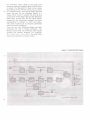
In the CD-4 record two sigAals are superimposed
on each wall of the same groove. One is the SUM
SIGNAL LF + La (or RF + Rs). The other is a
30 KHz carrier modulated itl frequency by the
DIFFERENCE SIGNAL LF - L8 (or RF .:. Rs).
Referring to the block diagram of Figure 5, the
compositesignal picked up b¥ the phone cartridge
is first passed through a circuit which provides
standard RIAA equalization. Its output signal is
split into two different paths: One path goes
through a Low Pass filter that lets only the sum
signal through to the ·mixing circuit while stop
ping the carrier. A separation adjustmentis included
in this path to compensate for the variation :in
output level from different cartri.dges. The bther
path .takes the signal through a High Pass Filter
which blocks the sum signal, but allows the
modulated high frequency carrier -to be presented
to the FM Detector, after amplification to
the proper level. There, the difference signal is
recovered (detected) by means of a low distortion
Phase Locked Loop circuit. The 30 kHz level is
automatically adjusted to suit different types of
cartridges and set-up conditions.
The Low Pass filter that follows the FM detector
suppresses any vestiges of the high frequency
carrier, leaving only the original difference signal.
fn recording, the frequency response of the differ
ence signal is modified to improve signal-to-noise
ratio and crosstalk. The circuits labelled De
emphasis and AN RS in the CD-400B block diagram
are intended to restore the original response of
~,
Figure 4. Cartridge Mounting
I
WRONG
RIGHT
\
I
\
I
\
..
I
I
J
I
V
,
\
I
-
-,
~
-,
I
,--
.
CARTRI.DGE
90°
RECORD
SURFACE
a..-_~
RECORD
_ _.. SURFACE
r---WRONG
I
--:-;-""'-_J
RECORO
SU AFACE .
the difference signal while at the same time
reducing noise and crosstalk. When a CD-4 record
is played, the Muting/4-CH Radar circuit senses
the presence of the 30 kHz, carrier and, by means
of its special circuit, turns on the Radar light and
opens the path for the difference signals. If a
regular stereo record is played, the same Muting
circuit shuts off the Radar light and the difference
signal path, so that on'ly the sum signal (which
contains all the information necessary for stereo
reproduction) is allowed to reach the output.
This same function can be manually performed
with an external pushbutton.
Once the sum and difference signals have been
recovered, the rest is simple' arithmetic. The
Mixing Circuit adds and subtracts these signals
yielding the discrete channels. For example:
(LF + Ls) + (LF -La) = 2 LF.The other three
channels are derived in a similar manner.
Figure 5. Functional Block Diagram
1JO---oRs
G-ENERAL SPEC FICATIONS
SER\JICE NOTES
Power Requirements .. 120V AC, 50 to 60Hz
Power Consumption
, .. 10 Watts
Dimensions ... . . . . . . . . .. Width: 8-1/4 inches
Height: 3-7/8 inches
Depth: 12·314 inches
Weight
, Unit Alone: 7.37 lbs.
Shipping: 8.70 lbs.
REPAIRS
Figure 6. Packing Instructions
Only the most competent and qualified service
technicians should be allowed to service the
Marantz Model CD-400B.
The Marantz Company and its warranty station
personnel have the knowledge and special equip
ment needed for the repair and calibration of this
precision instrument.
In the event of difficulty, write directly to the
factory (to the attention of the Technical Service
Department) for the name and address of the
nearest Marantz warranty or authorized service
station. Please include the model and serial num·
ber of the unit together with a description of the
problem,
If it should ever be necessary to ship the unit to
the factory or authorized service station, pack
the unit carefully using the original packing ma
terial. If the packing material has been discarded,
lost or damaged, write to the factory (to the
attention of the Technical Service Department)
for new packing material. Carton, fillers and
packing instructions will be returned to you at
a nominal charge.
No unit should be returned to the factory wjth~
out an Authorized Return·· Label, which the
Marantz Company will supply if the description
of difficulties appears to warrant factory service,
Please pack theCD·400B as illustrated in Figure 6.
Insure the Model CD-400B for its full value. Make
sure that your correct return address is on the
shipping label. Ship via a reputable carrier. (DO
NOT USE PARCEL POST.) Be sure to obtain a
receipt from the carrier.
The Sound of Marantz
is the compelling warmth of a Stradivarius.
It
IS
a dancing flute, a haughty bassoon
and the plaintive call of a lone French horn.
The Sound of Marantz is the sound of beauty,
and Marantz equipment is designed to bring you
the subtle joy of its delight.
Wonderfui adventures
In
sound await you
when you discover 'that the Sound of Marantz
is the sound of music at its very best.
PRINTED IN JAPAN
2922851010