1
...
o
--o
o
Compumotor Division
Parker Hannlfin Corporation
pIn 88-011728-01 A
Parkar
Contents
Table Of Contents
How To Use This User Guide .............................................................................................................................. iii
Assumptions........ .............................. ............... .......................................................................... ..... iii
Contents of This User Guide ................................................................................................................ iii
Installation Process Overview ........................................................................................................................... iii
Developing Your Application ................................................................................................................ iv
Installation Preparation ............................................................................. ,....................................... .. iv
Conventions ........................................................................................................ ,..................... .................... iv
Commands ....................................................................................................................................... v
Warnings & Cautions ........... " ................................................................... ,........... " . . .. . . . . . . . . . . . . . . .. . .. . . ... v
Related Publications ..............................................................................................................., . . . . . . . . . . . . . . .. . . . . . ... v
Chapter 1. Introduction ....................................................................................................... 1
Product Description..................................................................................................................... . . . . . . . . . . .. . . .. . . .. 1
Product Features .................................................................................................. ,..................... .. . . . . . . .. . .. . .. . . .. 2
Chapter 2. Getting Started ................................................................................................... 3
What You Should Have ............................................................................................................... , ..................... 3
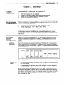
Basic System Configuration .............................................................................................................................. 3
Indexer Setting .............................................................................................................................. . .. 4
Establish Communications .................................................................................................................. 4
Drivellndexer Connection .................................................................................................................... 6
Making an Open loop Move.................................................. .... .. .... .. .. .. . .. . .. .. .. .. .. .. .. .. . .... .. .. .. . .. .. .. . .. .. . . .. 6
Making a Closed Loop Move.............................................................. . . .. . . . . .. . . . . . . . . ... .. . . . .. . . . . . . . . . .. ... . . . . . . . .. 7
8-Bit Outputs .................................................................................................................................... 8
8-Bit Inputs. ......................................... ............... ............................. ............................................ . .... 8
Sample Program for 5-Slot Rack ................... '" .............................................. ........................ .......... ... .. 10
Chapter 3. Installation ........................... _............................................................................ 15
Environmental Considerations ........................................................................................................................... 15
Complete System Configuration ......... '" . .. . .. . . . . . . . .. . .. ... ... . . .. . . . . . . . . .. ... .. . . . . . . . . . . . . . . . . . . . . . . . .. . . . .. . .. . . .. . . . . . . . .. . . . . . . . . . . . . . .. . . ... 15
PLC Port Addressing .................................. " ......................................... " .. . . . .. . . . . . . . . . . . ... . . . . . . . . .. . .. . . . . . . . .. 15
Indexer Insertion....................................................................................................................... .... .... 16
System Connections................................. ...................... ................................... ......................................... ..... 16
Verifying Proper Installation .............................................................................................................................. 17
Inputs & Outputs.................. . .. ... .. . . . . . . . . . . . . . . . . . . .. . .. .. . .. . . . .. . . . .. . .. . . . . . .. . ... . .. . .. . . . . . . . . . . . .. . . . .. . . . . .. . . ... . . . . . . . . . . . . . . 19
Chapter 4. Application D•• lgn ............................................................................................... 21
Motion Control Concepts .............................................................................................................................. . . . . 21
Move Profiles ...................................................................................................... '. . . . . . . . . ... . .. . .. . . . . . . . . . .. 21
Incremental vs. Absolute Positioning..................................................................................................... 22
Modes Of Operation .............................................................................................................................. . . . . . . . . .. 23
Immediate R~232C Mode ................................................................................................................... 23
Interactive Edit Mode ......................................................................................................................... 24
modes of operation ............................................................................................................................ 27
Program Design ............................................................. .. . . . . . . . . . . . . . . . . . . . . . . . . . . . . . . . . . . . . . . . .. . . . . . . . . . . . . . . .. . . .. . . . . . .. . .. . .. . . ... 27
Sequences ............. . ... . . .. ...... . . .. .. .. .. . .. . . . . . . . . . . .. ... .. .. .. .. . . . . . .. . . .. . . . .
. . . . . . . . . . . .. . . .. . . . . . . . . .. . ... . . . . . . . . .. 27
Trigger Inputs .................................................................................................................................... 28
Programmable Outputs.................................. ........... ............................................... ........................ ... 29
lime Delays ....................................... , .. .. .. . .. . . .... . . .. . .. .. .. ... . .. .. .. .. . ... . . . .. .. . ... .. . .. .. .. . .... . .. . .. . .. . .. .. . .. . .. . .. . ... 29
Branching ............................................................................................................................... . . . . . . . . . 29
Umits .............................................................................................................................................. 29
Chapter 5. Software Reference ............................................................................................. 31
DeScription of Format " ..................................................................................................................................... 31
Special Commands ................................................................................................ , ........ , . . . . . . . . .. . .. . . . . . . . . . . . . . . . . . . . 33
General Command Usting ............................................................................................................................... .. 34
Chapter 6. Hardware Reference ............................................................................................. 65
Environmental Specifications............................................................................................................................ 65
Electrical Specifications................................................................................................................... . . .. . .. . . . . . . . .. 65
Power Supply Requirements ................................................................................................................ 65
Serial Communications(R~232C) ......................................................................................................... 65
10-Pin Screw Terminal Connections ... '" ................................................................................................. EX)
LEDs ............................................................................................................................................... 67
System Specifications................................................................................................................... .............. .... 67
110 Specifications.................................................................................................................. . . . . . .. . . ... 67
Memory ........................................................................................................................................... 67
Chapt.r 7. Troubleshooting .................................................................................................. 69
Troubleshooting................................................................................................................. ............... ......... ..... EB
Problem Isolation..................................................................................................................... .. ... . . ... EB
Reducing Electrical NOise ............................................................................... , . .. . .. . . . . . .. . ... . .. . . . . . . . . .. . .. . .. EB
~232C Communications............................ .......................................... ............................................. EB
Encoder Feedback.............................................................................................................. . . . . .. . ... . . . .. 71
App.ndlces ...................................................................................................................... 73
Command Listing ............................................................................................................................................. 73
Warranty ............................................................................................................................... . . .. . . . . . . . . . . . . . . . . . ... 74
Glossary .............................................................................................................................. . .. . .. . . . . . . . . . . . .. . . . ... 77
Index ............................................................................................................................. 81
II
Mode/301 User Guide
List Of Figures
Figure 1-1. Model301-Front Panel .................................................................................................................. 1
Figure 1-2. Sample Model 301 Configuration ....................................................................................................... 2
Figure 2-1.
Figure 2-2.
Figure 2-3.
Figure 2-4.
Figure 2-5.
Figure 2-6.
Basic System Wiring Diagram..... ............................................................. ........................ ............. ....
Location of Jumper for Standard Card Cage ........................................................................................
Inserting a Model 301 into a Rack .....................................................................................................
RS-232C Connection............................................................................. .............................. ...........
Model 301/Drive Connections ..................... ......................................................................................
5-Slot Rack Component Arrangement....................................................................... .........................
3
4
6
10
Figure 3-1.
Figure 3-2.
Figure 3-3.
Figure 3-4.
PLC Port Addresses................ ................ ................................... ....................................................
Location of Jumper for Standard Card Cage ........................................................................................
Complete Configuration............ .............. ............................ ....................................................... ......
Homing Operation. .................................. ................................... ....................................................
15
16
16
18
4
5
Figure 4-1. . . . . . . . . . . . . . . . . . . . . . . . . . . . . . . . . . . . . . . . . . . . . . . . . . . . . . . . . . . . . . . . . . . . . . . . . . . . . . . . . . . . . . . . . . . . . . . . . . . . . . . . . . . . . . . . . . . . . . . . . . . . . . . . . . . . . . . . . . . . . . . . . .. 21
Figure 5-1. Open-Loop Homing Operation .......................................................................................................... 48
Figure 5-2. Closed-Loop Homing Operation........................................................................... . . . . . . . . . . . . . . . . .. . .. . .. . . . .. 48
Figure 6-1.
Figure 6-2.
Figure 6-3.
Figure 6-4.
R5-232C Serial Communications .................................................... .... '" ... ..................... ....................
12 Pin 110 Connector........ ............ ............ ................................... ....................... ............ ............ .....
Typical Input Circuit .................................. ....................................................................................
Typical Output Circuits ...................................................................................................................
65
65
65
fiT
List Of Tables
Table 2-1. Model 301 Ship Kit Ust .................................................................................................................... 3
Table 2-2. Input Bit Command Structure ............................................................................................................ 8
Table 3-1. R5-232C Pin-Out ............ . . . . . . . . . . . . . . . . . . . . . . . . . . . . . . .. . . . . . . . . . . . . . . . . . . . . . . . . . . . . . . . . . . . . . .. . . . . . . . . . . . . . . . . . . . . . . . . . . . . . . . . . . . . . . . .. 17
Contents
III
How To Use This This user gUide is designed to help you install, develop, and maintain your
system. Each chapter begins with a list of specific objectives that should be
User Guide
met after you have read the chapter. This section is intended to help you find
and use information in this user gUIde.
Assumptions
To use this user gUide effectively, you should have a fundamental
understanding of the follOWing information.
•
IBM (or IBM -compatible) computer experience
•
Basic electronics concepts (voltage, switches, current, etc.)
•
Basic motion control concepts (torque, velocity. distance, force, etc.)
•
BasiC serial communication concepts (e.g., RS-232C)
•
PLC programming
With this level of understanding. you can effectively use this user gUide to
install, develop. and maintain your system.
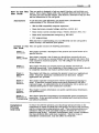
Contents of This This user gUide contains the following information.
User Guide
Chapter 1:
Introduction
This chapter provides a description of the product and a brief review of its
specifiC features.
Chapter 2:
Getting Started
This chapter contains a list of items you should have received with your
shipment. It will help you become familiar with the system and ensure that
each component functions properly. You will configure the system properly
in this chapter.
Chapter 3:
Installation
This chapter will help you properly mount the system and make all
electrical connections. Upon completion of this chapter, your system should
be completely installed and ready to perform basic operations.
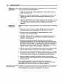
Chapter 4:
Application
Design
This chapter will help you customize the system to meet your application's
needs. Important application considerations are discussed. Sample
applications are provided.
Chapter 5:
Software
Reference
This chapter explains Compumotor's X-Series programming language in
detail. It deSCribes command syntax and system parameters that affect
command usage. An alphabetical list of all commands, with a syntax and
command description for each command is included.
Chapter 6:
Hardware
Reference
This chapter contains information on system specifications (dimensions
and performance).
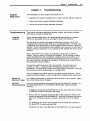
Chapter 7:
Maintenance &
Troubleshooting
This chapter deSCribes Compumotor's recommended system maintenance
procedures. It also provides methods for isolating and resolving hardware
and software problems.
Installation
Process
Overview
To ensure trouble-free operation, you should pay special attention to the
environment in which the Model 301 will operate. the layout and mounting.
and the wiring and grounding practices used. These recommendations are
intended to help you easily and safely integrate the Model 301 into your
manufactUring faCility. Industrial environments often contain conditions
that may adversely affect solid state equipment. Electrical noise or
atmospheriC contamination. may also affect the Model 301.
Iv
Mode/301 User Guide
Developing Your Before you develop and implement your application. there are several issues
Application
that you should consider and address.
1. Clarify the requirements of your application. Clearly define what you
expect the system to do.
2. Assess your resources and limitations. This will help you find the most
effiCient and effective means of developing and implementing your
application.
3. Follow the gUidelines and instructions outlined in this user guide. Do not
skip any steps or procedures. Proper installation and implementation
can only be ensured if all procedures are completed in the proper
sequence.
Installation
Preparation
Before you attempt to install this product. you should complete the following
steps:
1. Review this entire user guide. Become familiar with the user gUide's
contents so that you can quickly find the infonnation you need.
2. Develop a basiC understanding of all system components. their
functions. and interrelationships.
3. Complete the basic system configuration and wiring instructions (in a
simulated environment. not a permanent installation) provided in
Chapter 2. Getting Started.
4. Perform as many basic moves and functions as you can with the
preliminary configuration. You can only perform this task if you have
reviewed the entire user gUide. You should try to simulate the task{s) that
you expect to perfonn when you permanently install your application
(however. do not attach a load at this time). This will give you a realistic
preview of what to expect from the complete configuration.
5. After you have tested the system's functions and used or become familiar
with the system's features. carefully read Chapter 3. Installation.
6. After you have read Chapter 3 and clearly understand what must be done
to properly install the system. you should begin the installation process.
Do not deviate from the sequence or Installation methods provided.
7. Before you begin to customize your system. check all of the system
functions and features to ensure that you have completed the installation
process correctly.
The successful completion of these steps will prevent subsequent
performance problems and allow you to isolate and resolve any potential
system difficulties before they affect your system's operation.
Conventions
To help you understand and use this user guide effectively. the conventions
used throughout this user guide are explained in this section.
Contents
Commands
V
All commands that you are instructed to enter are displayed in all capital
letters. just as they appear on the tennfnal (vertically). A one-line
explanation of the command is provided next to each example. The
command is displayed in boldface. Be sure to separate each command with a
space (press the space bar). Press the carriage return key to execute the
commands on a specific line. In this user gUide. commands are often shown
in a vertical fashion so that a short explanation of each command can be
provided. Refer to the example below.
Command
> AS
> VS
>
>
Dl{ll{ll{ll
G
Description
Sets acceleration to 5 rps2
Sets velocity to 5 rps
Sets distance to 1.000 steps
Executes the move (Go)
On your computer screen or terminal, the command string shown above
would actually look like the example shown below.
vs Dl{ll{ll{ll G<cr>
Responses are set in all capital letters. as they are on the terminal. An
example is provided below.
>
AS
Command
> RV
Response
*92-011 00 6-01A4
The system generally ignores command syntax that is not within the valid
range for a specific command (valid ranges are provided in Chapter 5.
Software Reference). Compumotor does not guarantee system performance
when the system executes commands that contain invalid syntax or are
outside of the valid range.
Warnings &
Cautions
Warning and caution notes alert you to possible dangers that may occur if
you do not follow instructions correctly. Situations that may cause bodily
injury are presented as warnings. Situations that may cause system damage
are presented as cautions. These notes will appear in bold face and the word
warning or caution will be centered and in all capItal letters. Refer to the
examples shown below.
WARNING
Do not touch the motor Immediately after It has been In use for an extended
period of time. The unit will be hot.
CAUTION
System damage will occur If you power up the system Improperly.
Related
Publications
The following publications may be helpful resources.
Seyer. Martin. RS-232C Made Easy: Connecting
Computers. Printers. Terminals and Modems.
Englewood Cliffs. New Jersey: Prentice Hall. Inc .. 1984
Current Parker Compumotor Motion Control Catalog
Schram, Peter (editor). The National Electric Code Handbook
rrhird Edition). Quincy, MA: National Fire Protection
Association
Operations manual for the PLC that you will use with the
Model 301 Indexer
j
j
j
j
j
j
j
j
j
j
j
j
j
j
j
j
j
j
j
j
j
j
j
j
j
j
j
j
j
j
j
j
j
j
j
j
j
j
j
j
j
j
j
j
j
j
j
j
j
j
j
Chapter 1. Introduction
1
Chapter 1. Introduction
The infonnation in this chapter will enable you to understand the
product's basic functions & features.
Chapter
Objectives
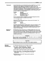
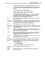
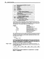
Product
Description
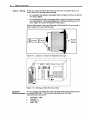
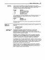
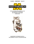
The Model 301 Indexer is designed for plug-in compatibility with the Texas
Instruments' Series 305™ PLC and the GE Fanuc Series One™ PLC.
Conservative electrical design and complete optical isolation of external
signals maintain the industrial ruggedness of the PLC. The Model 30 1 is a
single axis controller that accepts quadrature encoder feedback. Figure 1-1
shows the Model 30 l's front panel.
With a standard 3-wire RS-232C interface, the Model 301 uses an extended
form of Compumotor's X Series Language for ease of programming and
flexibility of interactive control with the PLC rack. The Model 301 has an
on-board editor that provides complete program creation, modification. and
monitoring through a remote terminal. As programs are written, they are
automatically stored in nonvolatile memory. Execution may begin at any
point in the stored program as designated by the PLC program or through the
RS-232C port. The point at which motors are commanded to move depends
on PLC contacts. time. and position information. You can even program the
Model 301 to tum on and off outputs of the PLC within the execution of its
own program. This bus-compatible product provides complete backplane
integration between the PLC and the motor.
MODEL 301
INDEXER
ELSY
ED
•
t.OVfIG
EXT. v+
EXT.GNl
STEP
DIR
ENC.CHAA+
ENC.CHAAENC.CHAB+
ENC.CHABENC.CHAZ+
ENC.CHAZ·
N.c.
Figure 1-1. Model 30 I-Front Panel
There is a home input line for the axis to decouple the scan time of the PLC
for sensing motor horne positions.
2
Mode/301 User Guide
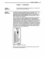
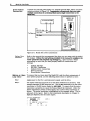
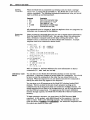
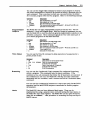
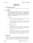
The Model 301 controls a motor axis independent ofthe PLC's CPU. The
indexer is not burdened by PLC scan time limitations. The scan time of the
PLC is only pertinent in the communication between the Model 301 and the
PLC through the backplane. Figure 1-2 is an example of a Mode1301
configuration.
PLC
Model
301
+5V Power
Supply
o
Drive
Encoder
Figure 1-2. Sample Model 301 Configuration
Product
Features
•
•
Single-axis control with incremental encoder feedback
Plug-in bus compatibility with the 11 Series 305™ or GE Fanuc One™
PLC
•
Standard RS-232C programming interface and complete online editing
of the stored program
•
Programmable position, direction, velocity, and acceleration for precise
motion control
•
5VDC optically isolated inputs and outputs prOvide high electrical noise
immunity
•
2K or 8K battery-backed RAM memory to store multiple programs
•
Up to 63 separate indexer program entry pOints may be defined-complete
flexibility of indexer program execution from the PLC program
•
Integral high-speed inputs for accurate home sensor and sensorinteractive control
•
Commands support complex move profiles: velocity changes on-the-fly
triggered by time, position, or PLC contacts
•
Conditional control of program flow with
state of PLC contacts
•
•
On-line debugging with the Trace
(XTR)
IF
statements based on the
command
PLC output contacts may be set or cleared from the Model 30 l's programs
Chapter 2. Getting Started
3
Chapter 2. Getting Started
Chapter
Objectives
What You
Should Have
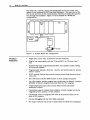
The information in this chapter will enable you to:
•
Verify that each component of your system has been delivered safely
•
Become familiar with system components and their interrelationships
•
Bench test the system
Inspect your Model 301 shipment upon receipt for damage to its shipping
container. Report any damage to the shipping company immediately.
Parker Compumotor cannot be held responsible for damage incurred in
shipment. The items listed in Table 2-1 should be present and in good
condition.
Pari/QuantitY
Pari Number
Model 301
Model 301 User Guide (1)
IndexerfDrive Cables(f)
Connector (1 )
RS-232C Cable (1)
88-011728-01 A
71-011159-10
43-011058-01
71-011319-10
1"UD~L301
Table 2-1. Model 301 Ship Kit List
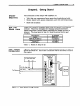
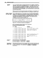
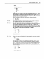
Basic System
Configuration
Figure 2-1 provides an overview of the connections you will have to make to
operate the Model 301. Each of the connections will be discussed in detail in
this chapter.
MODEL 301
NDEXER
+5V External Power Supply
GND
+5V
9-Pin
El.SY
e
•
....i---ll--+.D Conn9C1or
M:NN>
EXT.V+
EXTON)
STEP
DIR
ENC.CHAA+
ENC. CHAAENC.CHAB+
ENC. CHABENC.CHAZ+
ENC.CHAZt-D.E
N.C.
Figure 2-1. Basic System Wiring Diagram
Remote
Terminal
4
Mode/30t User Guide
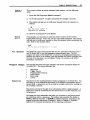
Indexer Setting
Before you insert the Model 301 into one of the PLC's available ports, you
must check the following indexer setting:
•
In a standard rack system, the jumper (refer to Figure 2-2) must be placed
over pins 1 and 2.
•
In an extended PLC cage, the jumper (refer to Figure 2-2) must be placed
over pins 2 and 3. The jumper disables the 1XX (octal) addresses on the
card. Figure 2-2 shows the location of the jumper.
Push in the buttons at the top and bottom of the Model 30 l's front panel to
Insert/remove the unit from the rack.
I
Ijl
Jumper I~: Pins
lill
_3..
Figure 2-2. Location of Jumper for Standard Card Cage
CUTPUT
INPUT
=::==::
"'00"""''''''00
.......:00 . . . . . . . . 0 0
D
I I ••
0000000
0000000
Model 000000
305000000
Figure 2-3. Inserting a Model3011nto a Rack
Establish
You can program the Model 301 with any ASCII device that COIIlll1unicates
Communications via standard RS-232C. The terminal's parameters for RS-232C
communications should be:
•
•
•
•
Baud Rate: 9,600
Stop Bit: 1
Data Bits: 8
Echo: Off
Chapter 2. Getting Started
5
The lfodel301 ~ echo.fimction is always on. Attach the RS·232C connection
from your ASCII device to the g·pin D connector on the front panel of the
Model 301 (refer to Figure 2-4). If you are using an IBM PC. an RS-232C cable
is provided.
.f""'..
I 00
•
•
•
II
7
RIC
TX
GND
ASCII
Device
o·
~0
V
•
Model 303 '·Pin Connector
Figure 2-4. RS-232C Connection
Testing
RS·232C
To ensure that the RS-232C connection is operating properly. complete the
following steps.
1. Apply power to PLC. If your tenninal is already on. you will see a
message indicating that the indexer is ready. Below the message. a
prompt (» should be present. Press the Return key. A new prompt should
appear. If you powered up your tenninal after the Model 301. press the
Return key. The tenntnal should display a prompt (».
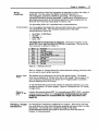
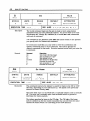
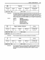
2. Type R and press the Return key. The Model 301 will display the
Dynamic Data. Registered Data. and Active Parameters. A sample Status
Report (R) command's response is shown below.
*DYNAMIC DATA
INPUT BYTE
(B0 - B7) =
OUTPUT BYTE (B0 - B7) =
HOME: = 1
*REGISTERED DATA
*
Inputs:
11=0 12=0 13=0
Outputs: 01=0 02=0 03=0
Motor position =+0
*
Encoder Position =+0
*ACTIVE PARAMETERS:
*
MR25000 GHV 1 GHF 0.1
FR00000000
ER 4000 DB5 DW250 CGa
*
VS0 V0 A0
*
MPI D+0 T0.5 L0
00000000
00000000
14=0 15=0
04=0 05=0 06=0
If you receive the data listed above. your RS-232C connection is working
properly. If you do not receive any response. check your wiring. and
perform the steps again. Some set-up values may be different. Before
proceed.Ing. remove power from the PLC.
6
Model 301 User Guide
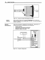
Drive/Indexer
Connection
Connect the external power (EXT. V+), external ground (EXT. GND), and drive
outputs as shown in Figure 2-5. Compumotor recommends that you make
multiple connections to a termlDal block and a slDgle connection to the
Model 301.
I
+5V External P - Supply
To Drive
~
TEP+'
DIR+ (Red)
GNO
".
I
+5V
MODEL 301
NDEXER
!fJl
~-"'------+-+-+4- ,,-llJ
STEP- (WMe)
;;
~~;,;,
• ~STEP
•
~~NC. CHAA+
DIR;.;.-...:.(Gr::;;.MI1=)_ _ _ _ _ _ _ _ _ _---l~~.~ ~DIR
•
.....- - ENC. CHA A-
•
.....
- - ENC. CHA B+
•
.....- - ENC. CHI>. B-
•
•
_ - - ENC. CHAZ+
rc~CHAZ
~"--N.C.
Figure 2-5. Model 30l/Drive Connections
Setting Drive
Functions
Refer to the manual that accompanied the drive you are using with the Model
30 1 Indexer. Follow the instructions provided in the manual to corlfigure the
motor and drive and complete 01111 settings (e.g., motor current). Before
proceeding. be sure that you have properly made all connections and
settings:
•
•
•
•
•
Making an Open
Loop Move
Indexer Settings
RS-232C Connection
Indexer /Drive Connection
Drive Functions
Drive/Motor Connections
To ensure that you have wired the Model 301 and the other components of
your system properly, use the following instructions to perform a move.
Step 1
Apply power to the PLC. external power supply, and the drive.
Step 2
The motor resolution must be set to the same resolution as the drive. This
example assumes 25,000 steps per rev. Use the MR command to set the motor
resolution to 25,000 motor steps/rev (MR2512100). To ensure that the motor
resolution is properly set. issue the Status Report (R) command. Under the
Active Parameters portion of this report. the current motor resolution is
shown. The motor resolution is highlighted in the example below. This is
only part of the report. Refer to the R command description in Chapter 5,
Software Reference for the entire report.
*ACTIVE PARAMETERS:
GHF0.1
*
MR25!/l!/lQJ GHVI
*
FR 00000000
ER 4000 DB 5 DW 250 CG B
VS0
V0 A0
MPI
D+
T0.5
L0
Chapter 2. Getting Started
Step 3
7
Using the tenntnal. enter the following conunands:
>
>
>
MPI
FR""""""""
V5 025000
A5
G<cr>
Please note the spaces between the conunands and the carriage return after
the Go (G) conunand. A descrtption of each command is given below.
Command
> MPI
FR""""""""
>
> A5
> V5
> 025000
> G
Description
Sets to Incremental mode
Clear any saved FS parameters
Sets acceleration to 5 rps2
Sets velocity to 5 rps
Sets distance to 25,000 steps
Executes the command (Go)
The motor should move 25.000 steps in the CW direction. The moving (Red)
LED will be on whUe steps are being sent. If the motor does not move. check
the wiling and refer to Chapter 7. Troubleshooting.
To make the motor move in the CCW direction. enter the following
commands:
Command
> B
> G
Description
Changes the direction of movement
Executes the command (Go)
The previous acceleration. velOCity. and distance parameters are used
move. It is simply performed in the CCW direction.
in
this
Making a Closed To make a closed-loop move a 1.000 line (4.000 pulse post-quadrature)
Loop Move
encoder must be wired to the Model 30 1. When ready. enter the following
commands.
Command
> PZ
> FSBl
> FSCl
> FSOl
> FSBl
ER4"""
>
> A5 V5 04""" G
Description
Zero motor and encoder positions
Enter closed loop mode
Enable position maintenance
Enable stop on stall
Enable stall detect
Set encoder resolution to 4,000 pulses/rev
Motor should move 1 rev CW
When the move is complete enter R.
The partial response from the terminal should be:
REGISTERED DATA
Inputs:
Outputs:
Motor Position = +25000
Encoder position = +4000
If the encoder pOSition is 0 or a message is sent indicating that the motor
stalled. the encoder is not properly connected (refer to Chapter 7.
Maintenance and Troubleshooting).
If the encoder pOSition is negative H. the encoder phases are reversed (refer to
Chapter 7. Maintenance and Troubleshooting).
When the motor is finished moving enter:
> B G
> R
The motor and encoder positions should both be at 0 again.
8
Mode/30t User Guide
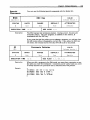
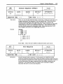
8-Blt Outputs
The Model 301 Indexer has outputs to the PLC. These outputs are transmitted
on the upper octal addresses. If the card is in the slot to the left of the Series
One™ CPU. the outputs from the indexer card (which are inputs to the PLC)
would occupy an address space from 100 to 107. The address 100 corresponds
to B0 and 107 corresponds to B7. Refer to the example below (refer to Figure
3-1 for more information on rack addresses). if you are using an extended
card cage. the output bit addresses are not available (refer to the Indexer
Setting section earlier in this chapter).
The PLC may use the most stgntftcant two output bits (B7 & 86) to determine
indexer status. These two bits indicate whether the indexer is executing a
user program (i.e .. Proqram Busy) or if the indexer is sending pulses (Le ..
Motor Busy). The other bits are general-purpose outputs that are
controlled by the indexer and its program. The protocol of these outputs is
shown below:
1; The motor is moving. the indexer is sending pUlses.
86 ; 1; A sequence is being executed.
85 - 80 ; 1; You can set these general outputs to any logic
87 ;
level in immediate mode
or under program control. Outputs are labeledfrom 1 to 6. Zero (0) is not used.
The outputs are initialized to a logic zero on power up. If the PLC is turned
from RUN mode to PROGRAM mode or LOAD mode. all of the outputs will go to
a logic one (1) and the execution of any commands will be disengaged. When
the unit is returned to RUN mode. the outputs will be reset to a zero state.
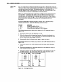
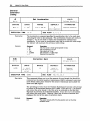
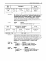
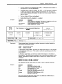
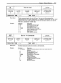
8-BIt Inputs
The Model 301 Indexer card looks like an 8-bit output card to the Series
OneTM PLC. If the card is in the slot to the left of the Series One™ CPU. the
eight inputs (which are outputs from the PLC) would have the address space
from 00 to 07. The PLC output at address 00 is the B0 input bit to the indexer
card and address 07 corresponds to B7. The input addresses that correspond
to B0 - B4 are shown below.
84
83
82
81
80
IS
I4
J3
12
n
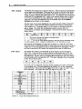
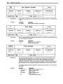
You must use the command structure shown in Table 2-2 to issue commands
to the indexer card. The most Significant bit (MSB)-B7-is the command
valid strobe line. When this line is toggled from low to high. the other 7 bits
have valid data. The strobe line must stay high for at least 1 ms.
COMMAND
87
XG#
0->1
KILL
0->1
KILL & RESET OUTPUTS
0->1
STOP
0->1
STOP & RESET OUTPUTS
0->1
HOME (+)
0->1
HOME(-)
0->1
PAUSE
0->1
RESUME
0->1
R
0->1
PR
0->1
PR
0->1
PR
0->1
RESET OUTPUTS
0->1
GENERAL INPUTS
x
-> = logic transition x = don't care
Table 2-2. Input Bit Command Structure
86
85
84
0
1
1
1
1
1
1
1
1
1
1
1
1
1
1
AS
0
0
0
0
0
0
0
0
0
0
0
0
0
1
M
0
1
0
1
0
0
0
0
1
1
1
1
1
15
83
A3
82
K2.
0
0
0
0
0
1
1
1
1
1
1
1
0
14
0
0
0
0
1
0
1
1
0
0
0
0
0
13
81
80
A1
0
0
1
1
A0
1
1
0
0
x
x
x
x
1
0
0
0
1
1
1
0
0
1
0
1
x
x
12
11
Chaeter 2. Getting Started
9
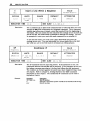
The following section defines each of the commands shown in Table 2-2.
XG,
This command executes a user program beginning from the sequence that
you define (#0 - #63). The least six bits (A0 - A5) are the program sequence
pOinter.
The address lines have the following weights:
AS
32
A4
16
A3
8
A2
4
A1
A0
2
To run sequence #35: A0, AI, and A5 (1 + 2 + 32 = 35) must be active. If
you instruct the indexer to execute a program that does not exist. it will
respond with a question mark (?). Instructing the indexer to execute
sequence 0 will run the first program in its memory.
KILL
This command allows you to terminate an output pulse train immediately.
with no deceleration.
KILL & RESET
OUTPUTS
This command allows you to terminate an output pulse train immediately
(with no deceleration) and reset all six of the general programmable outputs
to a logic low. Outputs are cleared at start of deceleration.
STOP
This command allows you to decelerate the motor to a stop.
STOP & RESET
OUTPUTS
This command allows you to decelerate the motor to a stop and reset all six
of the general programmable outputs to a logic low. Outputs are cleared at the
start of deceleration.
HOME.
The Home+ command searches for the home SWitch in the CW direction.
When the home switch for the axis goes low, the indexer searches for the CW
edge of the home switch (see Figure 3-5).
HOME·
The Home- command searches for the home switch in the CCW direction.
When the home switch for the motor goes low, the indexer searches for the
CW edge of the home switch (see Figure 3-5).
.
PAUSE
This command allows you to interrupt program execution.
decelerated (the same as an S command).
RESUME
The Resume command continues the execution of an interrupted sequence.
PR - POSITION
REPORT
This is a PosItion Report command. It provides axis encoder and motor
pOSition information. The information to be transmItted is selected by
setting appropriate bits:
•
•
Motion will be
B0 - Motor POSition
B 1 - Encoder Position
If both positions are requested, motor position is sent first.
R - DISPLAY
STATUS
Report current indexer status over RS-232C port
RESET
OUTPUTS
This command allows you to reset all six of the general programmable
outputs to a logic low.
10
Mode/301 User Guide
GENERAL
INPUTS
You can use these inputs as end-of-travellimits or for program conditional
branching. Note that the I's are labeled from 1 to 5. Zero (0) is not used. Upon
power up. the inputs are initialized low (logic 0). Information from the PLC
may be dynamically transmitted to the indexer card via the general inputs
when B5 and B6 are both high (logic 1). If either B5 or B6 go low. the last state
of the inputs are saved in the indexer card. The strobe line is not used to latch
the state of these inputs.
When you switch the PLC from Run mode to the Program or Load modes. the
general inputs are reset to logic 0 until the PLC re-programs a specific input.
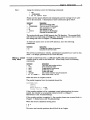
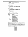
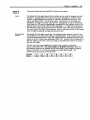
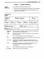
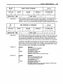
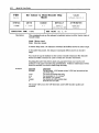
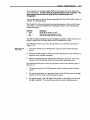
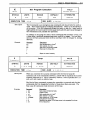
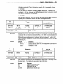
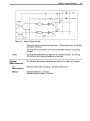
Sample Program
tor 5-Slot Rack
If you use the Model 301 in a 5-s10t rack. you can use the following program
example. The program can be used with an input Simulator. output module.
the Model 301. and a PLC programmer. The program allows the Model 301 to
control the output module's outputs or enables external devices to send
conunands to the Model 301 via the input module. The modules must be
arranged in the rack as shown in Figure 2-6.
Model 301
Errp1y
1npu1
Module
OutpU1
Module
CPU
Power Supply
Figure 2-6. 5-510t Rack Component Arrangement
Enter the following program with the PLC programmer.
Be sure the PLC's key Is set to PROG.
frQmm
Qa!<DI2DQn
1
CLR, SHF, 348, DEL, NXT
Clears PLC memory
2
4
6
STR,
STR,
STR,
STR,
STR,
STR,
STR,
STR,
SHF,
SHF,
SHF,
SHF,
SHF,
SHF,
SHF,
SHF,
10, ENT,
11, ENT,
12, ENT,
13, ENT,
14, ENT,
15, ENT,
16, ENT,
17, ENT,
STR,
STR,
STR,
STR,
STR,
STR,
STR,
STR,
SHF,
SHF,
SHF,
SHF,
SHF,
SHF,
SHF,
SHF,
130,
131,
132,
133,
134,
135,
136,
137,
i.m
8
10
12
14
16
18
21J
22
24
26
28
30
32
ENT,
ENT,
ENT,
ENT,
ENT,
ENT,
ENT,
ENT,
OUT,
OUT,
OUT,
OUT,
OUT,
OUT,
OUT,
OUT,
OUT,
OUT,
OUT,
OUT,
OUT,
OUT,
OUT,
OUT,
SHF,
SHF,
SHF,
SHF,
SHF,
SHF,
SHF,
SHF,
SHF,
SHF,
SHF,
SHF,
SHF,
SHF,
SHF,
SHF,
30,
31,
32,
33,
34,
35,
36,
37,
ENT
ENT
ENT
ENT
ENT
ENT
ENT
ENT
Writing :rom input module to indexer
module. The PLC reads the status of
the input module and sends the
command inputs to the Model 301.
0,
1,
2,
3,
ENT
ENT
ENT
ENT
ENT
ENT
ENT
ENT
Writing from indexer module to output
module. The PLC reads the Model
301's outputs and sets the
appropriate outputs on the output
module.
4,
5,
6,
7,
Turning On
Outputs
Turn the PLC's key to the RUN position.
To turn on outputs 1.3. and 5. enter: > 0112111211121
To turn on outputs 2. 4. and 6. enter: > 00112111211
Controlling the
Indexer With
Remote Inputs
This exercise will teach you how to program and store motion sequences and
activate the sequences from a remote input. First, you must use the tenninal
to create the sequences. You should enter the boldface and underlined
ins tructtons.
Chapter 2. Getting Started
(Turn off closed loop functions)
>~
> Are You Sure (YIN)?
> UlU
* (.1) 1: ...
X
Inserting Sequence I
* I:
*
>AS
> (Pre.,
YS
G IT
,.ey Agaln
P2SQH2/Qj
Inter
tq
(fr."
'Xlt;
Inter Kay'
Edit Hpde)
>~
* (.1)
5:
•.•
Inserting Sequence 5
*
5: >11 Vl p-25QjRlQJ C; IT
<pre.. Inter 'ey)
> (Pr."
Enter Ely Aglin to Ixit Bdit Mod9)
> l.ll
1: A5 V5 025000 G XT
5: Al VI 0-25000 G XT
* 1259 BYTES FREE. *
Zero Position
> U
> ~
Incremental move mode
*
The commands are described in detail below.
Command
> CLR
> EIR1
AS
V5
025"""
G
IT
>
EIR5
A1
V1
0-25"""
G
IT
>
LST
> PZ
> MPI
Description
Clears the indexer's memory
Begins definition of Sequence #1
Sets acceleration to 5 rps2
Sets velocity to 5 rps
Sets distance to 25,000 steps
Executes the sequence
Ends Sequence #1 definition
Begins definition of Sequence #1
Sets acceleration to 1 rps2
Sets velocity to 1 rps
Sets distance to 25,000 steps
Executes the sequence
Ends Sequence #5 definition
Lists current sequences #1 & #5
Sets the current position to zero
Sets the indexer to Incremental mode
We will now use the input Simulator to execute these two sequences and to
execute other commands. Refer to Table 2-2 for a complete list of the input
bit command structure.
First, you will ensure that the motor is set to position 0. This should have
been done with the Set Position Zero (pz) command you issued earlier. Set
the switches on the input simulator to the following settings to execute the
Position Report (PR) command:
00
1
81
0
0
B2
B3
84
85
86
B7
1
1
0
1
0
11
12
Model301 User Guide
Toggle B7 input (tum the input on and then om. The screen should display
the axis' motor position as +121. Now you can execute sequence # 1. Remember
the weights of the address lines:
32
A4
16
8
A2
A1
4
2
Set the switches on the input simulator to the following settings to execute
sequence #1 (XG1):
80
1
B1
0
0
B2
B3
84
1!5
86
B7
""
"""
Toggle B7 input. The X axis should tum 25,000 steps in the CW direction
when sequence # 1 is run. Now you will check the axis' position again to
determine if it made the move properly. Since it started at 0, it should be at
position 25,000 now. Set the input simulator to the following settings to
execute the Position Report (PR) command:
80
1
""
"
"
Toggle B7 input. The axis's position should be displayed on the screen as
81
B2
B3
84
1!5
86
B7
1
1
1
+25121121121 steps.
You will now execute sequence #5. Set the SWitches on the input simulator to
the following settings to execute sequence #5 (XGS):
80
1
"
"""
"
"
Toggle B7 input. Toggle Switch B7. The
81
B2
B3
1
84
1!5
86
B7
axis
should tum 25,000 steps in the
CCW direction when sequence #5 is executed. Now check the axis' position
again. Since it moved 25.000 steps in the CCW direction. it should be at
position 0 again. Set the input simulator to the following settings to execute
the Position Report (PR) command:
80
1
B1
""
"
"
B2
B3
84
1!5
86
B7
1
1
1
Chapter 2. Getting Started
13
Toggle B7 input. Axis X's position should be -H2I steps. Enter the following
commands through the terminal:
Command
> Me
> G
Description
Sets the indexer to Continuous mode
Executes the move (Go)
The axis should begin moving CCW. The indexer executes the command
parameters that were last used-sequence #5. The motor continues to move
beyond the -25.000 distance defined in sequence #5 because you are operating
in Continuous mode (the distance value has no meaning in this mode). To
stop the axis. you will set the input simulator to perform the Stop (s)
command. which will decelerate the motor to a stop. Set the input Simulator
as follows:
80
0
B1
1
B2
B3
0
0
0
0
~
B5
as
B7
1
0
Toggle B7input. Toggle Switch B7. The axis should stop. You can try other
patterns with the input simulator. Refer to Table 2-2 for additional remote
input commands.
Chapter 3. Installation
15
Chapter 3. Installation
Chapter
Objectives
The infonnation in this chapter will enable you to:
Environmental
Considerations
Parker Compumotor recommends that you operate and store your Model 301
under the following conditions:
•
•
•
•
•
•
•
Insert the unit into the PLC properly
Connect all electrical system inputs and outputs properly
Ensure that the complete system is installed properly
Perform basic system operations
Ambient Operating Temperature: 32°F - 122°F (O°C - 50°C)
Storage Temperature: -22°F - 185°F (-30°C - 85°C)
HUmidity: 0 to 95% non-condensing
The Model 301 is protected against short Circuit and over temperature.
Compumotor does not recommend that you test these features or operate
your system in such a way as to induce short circuiting or overtemperature
situations.
Complete
System
Configuration
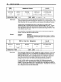
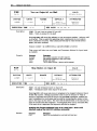
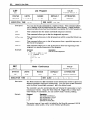
PLe Port
Addressing
Before you proceed with this section, you should have completed all of the
steps and procedures contained in Chapter 2. Getting Started. You should
already be familiar with the set-up procedures for communications. and
power.
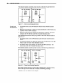
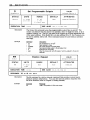
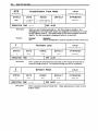
Each PLC port has a unique device address. The Model 301 will assume the
device address of the port in which it is inserted. You can insert the Model
301 Indexer into any available port. Figure 3-1 shows the standard addresses
given to PLC ports.
Outputs
130-137
B0-B7
120-127 110-117
BIi!!-B7
BIi!!-B7
100-107
BIi!!-B7
CPU
Inputs
Bli!l-B7
30-37
B0-B7
20-27
BIi!!-B7
10-17
Power Supply
B0-B7
00-07
Figure 3-1. PLC Port Addresses
Extended PLC
Cages
•
In a standard rack system. the jumper (refer to Figure 3-2) must be placed
over pins 1 and 2.
•
In an extended PLC cage. the jumper (refer to Figure 3-2) must be placed
over pins 2 and 3.
If you intend to insert the Model 301 into a PLC with an extended cage, you
must place the jumper on pins 2 and 3 of the indexer board before inserting
the indexer into the port. Figure 3-2 shows the location the jumper. Push in
the buttons at the top and bottom of the Model 301 's front panel to remove
the unit from the rack.
16
Model 301 User Guide
Figure 3-2. Location of Jumper for Standard Card Cage
Indexer
Insert/on
System
Connections
After you have properly set the jumper (if necessary), you can insert the
Model 301 Indexer into any available port of the PLC. You may now begin the
system connections.
This section will help you properly wire the Model 301. Specifically. the
following procedures and information will be addressed:
•
•
•
•
Wiring Guidelines
Establishing communications (RS-232C)
Wiring the external 5VDC power supply
Wiring the indexer to the drive
I
+5V External Power Supply
~
TEP+.
To Drive
OIR+ (Red)
GNO
I
MODEL 301
NDEXER
+5V
/~,--
STEP-(WMe)
OIR - (Green)
lrr
LtJ
-+++r-..
_
. . ._ _ _ _ _
;
~:;~
~ STEP
OIR
•• h..h.- ENe. CHA A+
•
•
~- - ENC.
•
•
ENe. CHA B+
~- - ENC. CHA B.....
_ENC.CI-\A.Z+
•
~~Cl-\A.Z
• h..-
CHA A-
...!... '--N.C.
_L!!!!EJ
Figure 3-3. Complete Configuration
Chapter 3. Installation
Wiring
Guidelines
17
Proper grounding of electrical equipment is essential to ensure the safety of
personnel. You can reduce the effects of electrical noise due to
electromagnetic interference (EMI) by grounding. All Compumotor
equipment should be properly grounded. A good source of information on
grounding requirements is the National Electrical Code published by the
National Fire Protection Association of Boston, MA.
For grounding follow PLC manufacturers recommendations.
Communications
You can program the Model 301 with any ASCII deVice that communicates
Via standard RS-232C. The terminal's parameters for RS-232C
communications should be:
• Baud Rate: 9,600 (fixed)
• Stop Bit: 1
• Data Bits: 8
• Echo: Off
The Mode1301~ echo.function is a.lwalIS on. The 9-pin D connector on the
Model30l's front panel proVides the RS-232C connections. The pin out for
this connector is defined in Table 3-1.
Pin 1#
Pin 1
Pin 2
Pin 3
Pin 4
PinS
Pin 6
Pin 7
PinS
Pin 9
Function
Not Used
TXD, Transmit Signal
RXD, Receive Signal
DTRtCTS, Always set at +10VDC
Signal Ground
Not Used
Signal Ground
Not Used
Not Used
Table 3-1. RS-232C Pin-Out
Refer to Chapter 2, Getting Started for communications testing procedures that
you can use to ensure proper operation.
External Power
Supply
The indexer card is powered by the PLC's rack power supply. The indexer
card uses a maximum of ISO rnA ofthe PLC's +9V supply. Thts is equal to 15
units of load as described in the Series One™ Programmable Controllers
Manual (distributed by GE/Fanuc).
To use the Model 301's inputs and outputs (on external connector), you must
proVide an external +5V power supply. Figure 3-3 illustrates the +5V wiring
configuration.
Wiring the
Indexer to the
Drive
Connect the external power (EXT. V+). external ground (EXT. GND), and drive
outputs as shown in Figure 3-3. CompumotOl' recommends that you make
multiple connections to a termlna1 block and a slng1e connection to the
Mode130l.
Verifying Proper You should have completely configured your system. This section will help
you verify tltat you have wired the system properly and ensure that it is fully
Installation
operational. You should have completed testing the RS-232C
Communications already (the steps for this test were first discussed in
Chapter 2, Getting Started).
18
Mode/301 User Guide
Homing The
Motor
You can initiate the Go Home function by issuing the Go Home (GH) command.
When you issue the GH conunand, you must include the direction that the motor
should use to search for home. The home limit input on the Model 301 is
optically isolated, and is normally off. You must use a normally open. loadactivated switch to ground to determine the home position.
When you command the motor to go home, it begins to move in the direction
you specified. It performs this move at the last defined acceleration and
velocity rates, and looks for the home Unlit input to go active. The indexer
searches for home to the CW edge. The CW edge of the home switch is defined
as the first switch transition that occurs if it is traveling in the CCW
direction) .
To test the Model301's homing function. connect a N.O. switch between
HOME and EXT GND. Enter the following command string.
Command
Description
Set go home velocity to 5 rps
Sets final go home velocity to 0.2 rps
Instructs the motor to go home in the CW direction
> GBVS
> GBF.2
>
GB+
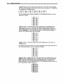
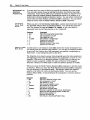
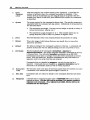
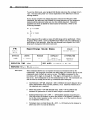
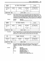
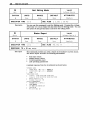
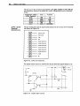
The following events occur when you go home in the CW direction (refer to
Figure 3-4):
1. The motor moves in the CW direction at 5 rps.
2. When the home switch is closed and opened, the motor decelerates to a
stop, then moves in the CCW direction at the velocity you specified with
the Go Home Final Speed (GHF) command.
3. Momentarily close the home switch again to stop the motor.
The following events occur when you go home in the CCW direction (refer to
Figure 3-5):
1. The motor moves in the CCW direction until the home switch becomes
active.
2. The motor decelerates to a stop and moves in the CW direction until the
home switch becomes inactive.
3. The motor creeps to the CW edge of the switch at the velocity you set with
the GHF command. The motor stops when the switch becomes active.
GH+ for CW Edge
GH- for CW Edge
Home
Switch
Active
Region
Home
Switch
Active
Region
>
~
CON
Edge
ON
Edge
<
CON
Edge
Figure 3-4. Homing Operation
ON
Edge
Chapter 3. Installation
Inputs &
Outputs
19
This section discusses the Model 30 1's inputs and outputs.
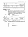
Inputs
The Model 301 has eight inputs. five of which can be used for program control.
Chapter 2. Getting Started contains a functional description of these inputs.
General progranunable inputs may be used for conditional branching. The
inputs are labeled from 1 to 5 (0 is not used). Upon power-up. the inputs are
initialized to a logic zero state untn the PLC reprograms an input specifically.
Data from the PLC may be dynamically transmitted to the indexer card via the
general inputs when B5 and B6 are both high Oogic 1). If either B5 or B6 go low.
the last state of the inputs are saved to the indexer card. The strobe line (B7) is
not used to latch the state of these inputs. You can also set the state of the inputs
with the TEST command through the RS-232C port.
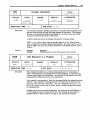
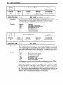
Programmable
Outputs
The Model 301 has eight output bits. The indexer card's outputs to the PLC are
transmitted on the upper octal address (IXX addresses). lfthe card is in the slot
to the left of the Series One™ CPU. the outputs from the indexer card (which are
inputs to the PLC) will occupy addresses 100 to 107. Address 100 corresponds to
B0 and address 107 is B7. if you are using an extended. rack system. the output
bits are not usable.
The PLC uses the most significant two bits of the outputs to determine
indexer status (B6 & B7). You cannot dtifi.ne or program these bits. These two
bits indicate whether the indexer is busy executing a user program (Program
Busy). or whether it is currently sending out pulses (Motor Busy). The
protocol of these outputs is shown below:
Address
Status
Chapter 4. ApPlication Design
21
Chapter 4. Application Design
Chapter
Objectives
Motion Control
Concepts
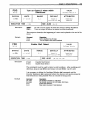
Move Profiles
Triangular and
Trapezoidal
Profiles
The infonnation in this chapter will enable you to:
•
Recognize and understand important considerations that must be
addressed before you implement your application
•
Understand the capabilities of the system
•
Use examples to help you develop your application
This section discusses basic motion control concepts that you should be
familiar with as you develop your application.
In any motion control application. the most important requirement is
precise pOSition. whether it be with respect to time or velocity. A motion
profile represents the velocity of the motor during a period of time in which
the motor changes position. The type of motion profile that you need
depends upon the motion control requirement that you specify. The basic
types of motion profiles are deSCribed below.
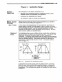
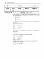
For indexing systems. you must define velOCity. acceleration. and distance
parameters before the system can execute a preset move. The value of these
parameters determines the motion profile as either triangular or
trapezoidal. A triangular profile results when the velocity and acceleration
are set such that the defined velocity is not attained before the motor travels
half of the specified distance. This results from either a relatively low
acceleration. a relatively high velOCity. or both. A triangular proille is
shown in Figure 4-1.
Triangular Profile
Trapezoidal Profile
Veloc~y
Veloc~y
(rps)
(rps)
1
I'"
la
Vmax Vavg 1a
Ie
ld
-
>1<
1e
>1'"
ld
>1
Vebci1y maximum
VeIoc:i1y average
Acceleration TIme
Constarrt Velocl1y TIme
Deoeleralion TIme
Figure 4-1. Triangular and Trapezoidal Proilles
A trapezoidal move proille results when the defined velocity is attained
before the motor has moved half of the specified distance. A trapezoidal
move may occur if you specify a low velocity with a high acceleration or a
long distance. The resulting motion proille will resemble the proille shown
in Figure 4-1.
22
Mode/301 User Guide
Incremental vs.
Absolute
Positioning
Incremental
Preset Mode
Moves
A preset move is a move in which you specify the distance (in motor steps).
You can select preset moves by putting the indexer into Normal mode (MN
command). Preset moves allow you to position the motor in relation to the
motor's previous stopped position (incremental moves) or in relation to a
defined zero reference pOSition (absolute moves). You can select incremental
moves with the Mode POSition Incremental (MPI) command. You can select
absolute moves with the Mode POSition Absolute (MPA) command.
When you are in the Incremental mode (MPI), a preset move moves the motor
the specified distance from its starting position. You specify the direction
with the optional (±) sign (D+2(lJ(lJ/HI or D-l(lJ/HI(lJ). or you can define it
separately with the Set Direction (H+ or H-) command.
Command
> MPI
> A2
> V5
>
>
>
>
>
Absolute Preset
Mode Moves
025"""
G
G
B
G
Description
Sets unit to Incremental Position Mode
Sets acceleration to 2 rps2
Sets velocity to 5 rps
Sets distance to 25,000 steps
Executes the move (Go)
Repeats the move (Go)
Reverses direction of next move
Executes the move (Go)
A preset move in the Absolute mode (MPA) moves the motor the distance that
you specify from the absolute zero position. You can set the absolute position
to zero with the Position Zero (pz) command, successfully completing a go
home move, or by cycling the power to the drive.
The direction of an absolute preset move depends upon the motor pOSition at
the beginning of the move and the pOSition you command it to move to. For
example. if the motor is at absolute position +12,800. and you instruct the
motor to move to position +5,000. the motor will move in the negative
direction a distance of 7,800 steps to reach the absolute pOSition of +5.000.
When you issue the Mode POSition Absolute (MPA) command, it sets the mode
to absolute. When you issue the Mode Position Incremental (MPI) command,
the unit switches to Incremental mode. The indexer retains the absolute
position, even while the unit is in Incremental mode. You can use the
POSition Report (PRA) or Status Request (R) commands to read the absolute
position.
Command
> MPA
> A2
> V1"
> PZ
01""""
>
> G
> 02"~"21"
> B
> G
>
> G
0"
>
MPI
Description
Sets unit to Absolute Position mode
Sets acceleration to 2 rps2
Sets velocity to 10 rps
Sets the current position to zero
Sets position to 10,000 steps
Executes the move (Go)
Sets position to 20,000 steps
Reverses the position of next move to -20,000 steps
Moves the motor to absolute position -20,000 (Go)
Sets the move position to 0
Executes the move (Go)
Sets indexer to Incremental Position mode
Chapter 4. Application Design
Continuous
Mode Moves
23
In the Continuous mode (MC), the motor will accelerate to its constant
velocity when you issue a G (Go) command. the distance command is ignored.
The motor will run at constant velocity until you issue a Stop or Kill
command (a command that interrupts motion).
Command
> FSBS
> Me
> A1S
> ViS
> G
Description
Sets unit to motor step mode
Sets unit to Continuous mode
Sets acceleration to 10 cps2
Sets velocity to 10 rps
Executes the move (Go)
In the example above, the motor will ramp up to 102 rps and continue to run.
You can command a new velocity while the motor is running with the
following commands.
Command
> vs
> G
Descriptipn
Sets velocity to 5 rps
Decelerates to 5 cps
The motor will decelerate from 10 rps to 5 rps using the previously specified
acceleration rate.
Modes Of
Operation
This section discusses the three modes of operation that are applicable to the
Model 301:
•
•
•
Immediate RS232C Mode
Immediate RS-232C
Interactive Editing
PLC Operation
The Model 30l's RS-232C interface port allows you to send motion
commands for immediate execution. You can also use this port to
interactively edit motion programs and sequences that are stored in the
Model 301's internal. nonvolatile memory. You can enter and edit sequences
from any RS-232C tenninal or computer.
Being able to execute commands as soon as they are received is espeCially
useful during set-up and debugging when you are installing the system or if
an application requires data from a remote computer or programmable
controller. All commands are composed of simple ASCII characters.
In Immediate mode, the indexer responds with a prompt (» when it receives a
valid command and a question mark (?) when it receives an invalid command.
If you enter a valid command, but enter an invalid range (e.g., A20), the Model
301 will respond with a question mark (?) . The interactive responses are
preceded with a carriage return and a line feed.
In Interactive Edit mode, the Model 30 I does not check syntax, command
validity. or ranges. You must execute a defined sequence to determine if it is
interpreted properly. Use the Trace (XTR) command to see where question
mark (?) appears to find invalid commands.
24
Model 301 User Guide
Sending
Character.
When the Model 301 is connected to a terminal. and you issue a carnage
return <cr>. a prompt will be provided (». The Mode13011s now ready to
receive commands. The following commands demonstrate what you would
type to perform an incremental move.
Command
> MPI
>
Al(lJ
> Vl
> D2S(lJ(lJ(lJ
> G
Description
Sets unit to Incremental mode
Sets acceleration to 10 rps2
Sets velocity to 1 rps
Sets distance to 25.000 steps
Executes the move (Go)
All commands listed in Chapter 5. Software Reference that are categOrized as
immediate can be executed in this fashion.
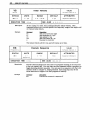
Requesting
Status
There are several commands that you can use to request status information
from the Model301's RS-232C port. You can also obtain this information
from a terminal or computer and use the data to debug the system. One
example of such a command is the Status Report (R) command. A sample
response from the R command is shown below.
"'DYNAMIC DATA
"'
INPUT BYTE
(B7 - B0) =
"'
OUTPUT BYTE (B7 - B0) =
"'
HOME: = 1
*REGISTERED DATA
Inputs:
11=0 12=0 13=0
Outputs: 01=0 02=0 03=0
Motor Position =+0
Encoder Position =+0
*ACTIVE PARAMETERS:
MR25000 GHV 1 GHF 0.1
FR01100000
ER 4000 DB5 DW250 CGB
VS0 V0 A0
MPI 0+0 T0.5 L0
00000110
00000000
14=0 15=0
04=0 05=0 06=0
Refer to Chapter 5. Software Reference for more information on status
commands (Le .. PRA. PRX. PX. and FR).
Interactive Edit
Mode
You can also use the Model 301's RS-232C interface to enter and edit
sequences. A sequence consists of several Model 301 commands. You should
be sure to enter the commands in the order that you intend them to be
executed. When the sequence is run. the system executes the commands in
exactly the order that they appear in the sequence.
You can store up to 63 sequences in the Model301's battery-backed RAM
memory. There is no limit to the size of each sequence as long as the
combined total of all sequences does not exceed the available memory. All
stored sequences do not have to be the same size (e.g .. two 50-byte sequences
and four 250-byte sequences). For applications that require additional
memory storage capacity. the Mode1301-M offers 8K of battery-backed RAM
memory.
To begin entering a sequence. you must issue the Edit Sequence (EXR)
command. At the prompt. enter EXR followed by the sequence # that you
want to create. Refer to the following example. The commands that you
enter are shown in boldface and underUned. The interactive responses from
the system are shown in plain type.
Chapter 4. Application Design
25
>~
* (.1)
10: ...
Inserting Sequence 10
*.10 >~
*
>~
>122 ~1/:!Il:!l11
>ii
>XT
*
*
>
At this point. you can begin to enter the commands for sequence # 10. Notice
that the Model 301 prompts you with an asterisk (*) and a bracket (» in the
Interactive Edit mode. To exit the Edit mode press the carnage return key on
an enpty line (cr/ or press the (esc) key.
Within the Interactive Edit mode. there are two editing sub-modes:
•
•
Fill mode
Edit mode
Fill Mode
This mode is used when no sequence exists-you are creating the sequence.
You canjUlline after line. just as in the example above
Edit Mode
You will automatically enter this mode whenever you edit an existing
sequence. The sequence and its line numbers will be displayed. You must use
the line-editor commands that allow you to insert. edit. or delete a line.
The following example demonstrates how to edit an existing sequence. When
you issue the EXR command. the Model 301 lists the sequence along with the
line numbers. You may now edit (E). insert (I). or delete(D).
> UJU..(4
* (. 1)
*
(.2)
10: A10
V10
*
(.3)
025000
*
(.4)
(.5)
G
XT
*
Editing Sequence 10
* >
Edit a Line
To edit a line. enter E. followed by the line number that you want to modify.
*
>~
*(.3)
0250000
*»
>P5f?JQJ9J"QJ
The Model 301 lists the line to be edited directly above the asterisk prompt.
This allows you to see what is currently stored in the line as you prepare to
edit it. To edit a line. you must re-enter the entire line (including the change
you want to make). When the entire line is re-written press the return key.
The Model 301 will automatically re-list the entire sequence so that you can
review the changes.
* ( .1)
*
(.2)
*
(.3)
* ( .4)
* ( .5)
10: A10
VI0
050000
G
XT
Editing Sequence 10
* >
26
Mode/3D 1 User Guide
Exiting Edit
Mode
If you press the Enter key while the cursor is on a blank line. the currently
stored line will remain unchanged. You can press the Escape <ESC> key at
any time to abort the editing session without changing the current line.
You can also exit the Edit mode by typing Q (QUit Editing ModeJ on a blank
line and pressing the Return key or by pressing the return on a blank line.
Listing
Sequences
You can list sequences with the LST conunand. This command lets you list
the entire contents of memory. specified sequences. or ranges of sequences.
LST
This command lists the entire nonvolatile sequence memory.
LSTnn
This command allows you to list the designated sequence.
LSTnn-nnn
This command allows you to list all sequences within a specified block (e.g ..
15 - 30).
LSTnn-
This command allows you to list all sequences from a specified sequence to
the end of the program.
LST- nn
This command allows you to list all sequences from the beginning of the
program to a specified sequence of the program.
When you list multiple sequences or enter LST63 the number of bytes of
program memory that are available will be displayed after the contents of
the sequences are displayed.
Inserting and
DeleUng Lines
When you are in the Edit mode. you can insert and delete lines in a sequence.
To insert a line. type the I command followed by the line number that
follows the point where you want to insert a new line. For example. if you
wanted to insert a line between lines #3 and #4. you would specify line #4 as
the point of insertion. Refer to the following example.
>~
• (,1)
., (.2)
., (.3)
.,
(.4)
* (.5)
10: A10
V10
025000
G
XT
Editing Sequence 10
* >l..-i
* (.4) Inserting
• » >ll±
*
(.1 )
* (.2)
* ( • 3)
* ( • 4)
* (.5)
* (.6)
10: A10
V10
050000
H+
G
XT
Editing Sequence 10
., >lL..!
.,
(. 4)
H+ Oeleted
.,*
(,1 )
( .2)
.,*
(.3)
10: A10
V10
050000
.
(.4)
(. 5)
G
XT
> Editing Sequence 10
* >
Chapter 4. App'ication Design
Deleting A
Sequence
27
If you want to delete an entire sequence from memory, use the following
steps.
1. Enter the Edit Sequence (EXRnn) command.
2. At the edit prompt (* », type D and press the carriage return. key.
3. The system will ask you to verify your request before the sequence 1s
deleted.
*
>~
Are You Sure (YIN)? Y
Sequence nn Deleted
nn refers to the sequence # to be deleted
Clearing
Memory
Occasionally. you may want to clear the entire contents of the batterybacked RAM memory. To do this. use the Clear (CLR) command. The system
will ask you to verify your request to clear the memory before performing the
task. Refer to the example below.
>~
Are You Sure (YIN)?
H
(Enter Y to clear)
>
PLe
Operation
Program Design
The Model 301 also communicates with the PLC processor (GE Fanuc One™
and 11 Series 3O5™) over the backplane communication bus. The PLC
program can instruct the Model 301 to execute a pre-progranuned sequence,
monitor the status of the indexer, and synchronize the motion program with
the rest of the machine it is controlling. (Table 2-2 contains a list of PLC
backplane commands.)
This section discusses the basic elements and issues of program design for
the Model 301. The issues addressed are:
•
•
•
•
•
•
Sequences
Sequences
Trigger Inputs
Programmable Outputs
Time Delays
Branching
Limits
Sequences are the building blocks of motion programs in the Model 30 1. You
can store up to 63 individual sequences in the indexer's nonvolatile batterybacked RAM. A sequences can be as small as a single command or as large as
the available memory.
Sequences can also be thought of as subroutines within a larger program. A
sequence is a list of commands that are executed one at a time when you run
the sequence.
The Model 301 has commands that allow you to branch to sequences based
on conditions within a sequence. The indexer also provides the ability to
GOTO a different sequence, or GOSUB to another sequence, return.ing to the
original point after execution is complete. Refer to Chapter 5, Software
Reference for detailed descriptions of the following commands.
28
Mode/301 User Guide
Sequence Programming/Editing Command.
EXR
I
E
D
Edit a sequence
Insert a line
Edit a line
Delete a line
Quit Edit mode
List seQuence(s)
Clear memory
Q
LST
CLR
Sequence Execution Command.
XR
Runs a sequence. When used within a sequence, it jumps to
execute another sequence, then returns to the original point, like
a GOSUB oornmand.
Exits the current sequence and executes the specified
sequence, like a GOTO command.
XG
Sequence Debugging Command.
XTR
TEST
EnablesJOisabies the Sequence Trace mode
Simulates the PLC inputs
Provides a status report of the indexer
R
XT
A sequence is a series of conunands. These conunands are executed in the
order in which they are progranuned (entered). Refer to the Interactive Edit
Mode section earlier in this chapter for an explanation of how to enter and
edit sequences. Two examples sequences are shown below.
Command
> LSTl-2
1:
2:
Description
Lists sequences 1 & 2
Sets acceleration to 10 rps2
Sets velocity to 10 rps
Sets the distance to 25,000 distance
Executes the move (Go)
Sets the distance to 50,000 distance
Sets axis to the CCW direction
Executes the move (Go)
Ends the sequence
Al(ll
V1(11
025(11(l1(li
G
05(11(11(l1(li
11G
XT
The conunands that you enter to define a sequence are presented vertically in
the previous example above. This was done to provide descriptions of each
command. You can actually enter as many conunands as you wish on each
line. separated by a space:
> LSTl-2
1: A10 V10 025000 G
2: 050000 H- G XT
In the two example sequences, only sequence 12 has an XI command at the
end. In this example, Vyou execute sequence 11, the Model 301 will execute
sequence 12 qJter sequence 11 is completed. ffyou execute only sequence 12,
the indexer will stop qJter the sequence is completed.
Trigger Inputs
The Model 301 has 5 trigger inputs that are controlled by the host PLC. To
recognize trigger inputs. the eight inputs from the PLC bus must be set by the
PLC program as follows.
X
87
86
85
84
83
82
81
80
x
1
1
I5
14
13
I2
n
Don't Care
Bits ItS & 16 must be ONfar the Model 301 to recognize bits f1J - 4 as trigger
inputs 1 - tJ respectively.
Chapter 4. ApPlication Design
29
You can use the Trigger ('1'a) command to instruct your program to wait for
the correct combination of inputs to be turned on before it proceeds with the
next command. This is one way in which you can synchronize the Model
301 's motion program with the PLC program. Refer to the following example.
Command
> Al9}
> Vl9}
> 0259}9}9}
>
TR9}9}9}9}1
> G
Programmable
Outputs
The Model 301 has eight programmable outputs to the PLC bus. 1\vo are
dedicated - Busy and Program Busy. With the Output (0) command. you can
use the Model 301 to turn the other six general programmable outputs on and
off within a sequence. The 0 command signals the PLC when some part of
your motion program is or has been executed.
Command
> MN
> Al9}
> Vl9}
> 0259}9}9}
>
>
TR9}9}9}"l
019}9}9}"
> G
Time Delays
Description
Sets indexer to normal preset mode
Sets acceleration to 10 rps2
Sets velocity to 10 rps
Sets distance to 25,000 steps
The move cannot be made until inputs #1 - #4 are off, and #5 is on
Turns output #1 on
Executes the move (Go)
You can use the Time ('1') command to delay execution of a sequence for a
preset period of time.
Command
> MN
> Al9} Vl"
> G
> Tl9}
> G
> XT
Branching
Description
Sets acceleration to 10 rps2
Sets velocity to 10 rps
Sets the distance to 25,000 steps
The move cannot be made until inputs #1 - #4 are off, and #5 is on
Executes the move (Go)
0259}9}"
Description
Sets indexer to normal preset mode
Sets the move parameters
Executes the move (Go)
Sets a time delay of 10 seconds
Executes the move (Go)
Ends the sequence
You can use the Conditional If (IF) command for conditional branching
within a program. This command tests the input conditions. If the
condition is true, all commands that follow the IF statement are executed. If
the conditions are not true, the Model 301 will skip all of the commands
associated with the condition. until it reaches an End of If Statement (NIF)
command.
You can use the Conditional If statement in conjunction with the XG (GarO
sequence) and the XR (GOSUB) sequence commands for flexible program
development.
Limits
The Model 301 does not have dedicated limit inputs. These can be
implemented by using a separate input card and moving the input status to
the Model 301 input data registers. The Model 301 can act upon the inputs
using the IF (IXXXXX) ... NIl' procedure or activating the Stop-on-input3
(FSF1) feature.
Chapter 5. Software Reference
31
Chapter 5. Software Reference
The infonnation in this chapter will enable you to:
Chapter
Objectives
•
Identify the five types of commands in Compumotor's X-Series Language
•
Use this chapter as a reference for the function, range, default. and
sample use of each command
Description of
Format
0PRA
0Position Request
0VALIO
Software Version A
0status
0SYNTAX
0UNITS
GRANGE
00EFAULT
0ATTRIBUTES
PRA
X = steps
None
None
Sequence/Immediate
SEXECUTION TIME
@RESPONSE
TO
<10
PRA
@SEE ALSO
ms
IS
See
pz, SP, R, PRX
Below
1.
Mnemonic
Code
This box contains the command's mnemonic code and the command type.
The command types are described below.
2.
Type
This portion ofthe box contains the command's type. The five command
types are listed below.
Edit
You can use edit commands to create or modify sequences.
Motion
Motion commands affect motor motion (I.e .. accelerate. velocity. distance. go
home. stop. direction. mode. etc.).
Programming
Programming commands affect programming and program flow. For
example. output. all sequence commands. time delays. loop and end loop.
and triggers.
Set-Up
Set-up commands define set-up conditions for the application. Set-up
commands include the following types of commands:
•
Status
3.
Full Name
FSA. FSB.
etc.
Status commands respond (report back) with infonnation.
This field contains the full command name.
32
Model301 User Guide
4.
Valid
Revision
Level
This field contains the revision history of the command. It includes the
revision of software when the command was added or modified. If the
revision level of the software you are using 15 equal to or greater than the
revision level listed in this field. your software will contain the connnands
as deSCribed.
5.
Syntax
The proper syntax for the connnand is shown here. The specific parameters
associated with the command are also shown. Definitions of the parameters
are deSCribed below.
n
This represents an integer. You may use an integer to specify a variety of
values (acceleration. velOCity. etc.).
s
This represents a sign character (+ or -). This variable allows you to
specify direction (CCW or CW) or a positive or negative value.
6.
Units
This field describes what unit of measurement the parameter is using.
7.
Range
This is the range of valid values that you can specify for n (or any other
parameter specified).
8.
Default
The default setting for the connnand is shown in this box. A command will
perform its function with the default setting if you do not provide a value.
9.
Attributes
This box indicates if the command is immediate. sequence or
sequence/immediate. The system executes immediate commands as soon as
it receives them. You will enter immediate connnands via an RS-232C
terminal (you must enter a carriage return after these connnands to execute
them). With the Model 301. sequence connnands are only executable in a
sequence. and in the order that they are received.
Connnands that are classified as sequence can only be executed in a
sequence. Commands that are classified as sequence/immediate may be
executed in the Immediate mode as well as within sequences.
10.
Execution
Time
The execution time is the span of time that passes from the moment you issue
a connnand to the moment the system begins to execute it.
11. See Also
Commands that are related or similar to the command described are listed
here.
12.
A sample status connnand is given (next to RESPONSE TO) and the system
response is shown. This ~ wUl only be provided if the system prouides a
response to the command. Uno response is prouided. this ~ will not be
included with the description.
Response
Chapter 5. Software Reference
33
You can use the following special commands with the Model 301.
Special
Commands
ESC
ESC Key
VALID
Software Version A
Edit/Motion
SYNTAX
UNITS
RANGE
DEFAULT
ATTRIBUTES
@
None
None
None
Immediate
EXECUTION TIME
<10 ms
I
SEE ALSO
s,
K
The ESC (escape) key tenninates motion. During a move. this key will
tenn1nate motion. The user program. in addition to the motion. is
teIminated with the ESC key.
Description
If you press the ESC key while you are editing a program. you will exit from
the Edit mode without changing the current line. If you press the ESC key
two times. the teIminal screen will clear (VflOO must be emulated).
@
Comments Delimiter
VALID
Edit
Software Version A
SYNTAX
UNITS
RANGE
DEFAULT
ATTRIBUTES
@
None
None
None
Sequence
EXECUTION TIME
<10 ms
I
SEE ALSO
D, E, EXR,
I, Q
Description
When you edit a program in the Edit mode. you may place comments on any
line after you enter the @ delimiter. Comments can be useful when you need
to briefly describe the procedure that a statement line will perfoIm.
Example
L
IF(I~XXX)
IF (II2I1XXX)
IF (I1I2IXXX)
IF(IllXXX)
N
XR5 NIF @ Run Set-Up
XR10 NIF @ Index 1
XR15 NIF @ Index 2
XR20 NIF @ Go-Bome
34
Model 301 User Guide
General
Command
Listing
A
Set Acceleration
VALID
Software Version A
Motion
SYNTAX
UNITS
RANGE
DEFAULT
ATTRIBUTES
Annn.nn
n = rps2
0.03 to 999.99
0
(motor dependent)
Sequence/Immediate
EXECUTION TIME
I
<10 ms
SEE ALSO
D,
v,
G,
R
Description
The Acceleration command specifies the acceleration rate to be used upon
executing the next Go (G) command. The acceleration remains set until you
change it. You do not need to reissue this command for subsequent G
commands. If you enter an acceleration rate that is outside the valid range.
the indexer will maintain the previous valid setting.
Example
Command
> MN
> AS
> V1111
>
01111111111111
> G
CG
DescriPtion
Sets the moves to mode normal (preset moves)
Sets acceleration to 5 rps2
Sets velocity to 10 rps
Sets distance to 10.000 steps
Executes the move (Go)
Correction Gain
VALID
Set-Up
Software Version A
SYNTAX
UNITS
RANGE
DEFAULT
ATTRIBUTES
<a>CGn
n = amount
of error to
correct
1-8
saved in
non-volitle
Sequence/
Immediate
EXECUTION TIME
Description
<10ms
RAM
I SEE
ALSO
FSB, FSC, DB, R
This command allows you to set the amount of error (steps) that should be
corrected on the initial pOSition maintenance (FSC1) command correction
move (which takes place whenever the motor is stationary and outside the
dead-band [DB) region).
The percentage of error that the Position Maintenance function will attempt
to correct on its correction moves is niB • 100%. If you set n to 1. the system
will correct the error slowly (I I B of the error is corrected on the first try).
This type of correction is performed smoothly. If you set n to B. the system
will correct the error faster. However. there may be more overshoot and
ringing at the end of this type of correction move.
Example
Command
CG3
Description
The system corrects 3/8 of the final-position error on the initial
correction move
Chapter 5. Software Reference
CLR
Clear Entire Program
VALID
Software Version A
Edit
SYNTAX
UNITS
RANGE
DEFAULT
ATTRIBUTES
CLR
None
None
None
Immediate
EXECUTION TIME
<10 ms
I
SEE ALSO
D, E, EXR, I, LST
This command clears (erases) the entire user program. The Model 301 will
prompt you to enter Y or N to verify your intentions before it erases the
memory. You can use the Delete (D) command to delete individual sequences.
Description
0
Set Direction & Distance
VALID
Motion
Software Version A
SYNTAX
O±nnnnn nn:--,
UNITS
n
EXECUTION TIME
Description
35
~
steps
<10 ms
RANGE
DEFAULT
ATTRIBUTES
±99,999,999
0
Sequence/Immediate
I SEE
ALSO
A, G, V, MN, MPA, MPI, SP, FSB, R
The Distance (0) command defines either the number of steps the motor will
move or the absolute position it will seek after you enter a Go (G) command.
In Incremental mode (MPIl. the value set with the 0 command will be the
distance (in steps) that the motor will travel on all subsequent G commands.
In Absolute mode (MPAl. the distance that the motor moves is the difference
between the current position and the zero position. The 0 command does not
affect continuous mode moves (MC). The 0 command specifies either motor
steps or encoder steps, depending on the mode (FSB).
Example '1
Command
MN
AS
V10
o 5 "11"21"
G
G
Example '2
Command
MPA
PZ
AS
V5
OS""""
G
G
Description
Sets unit to Normal mode (preset)
Sets acceleration to 5 rps2
Sets veloc~y to 10 rps
Sets distance to 50,000 steps
Executes the move (Go)
Executes the move, moves another 50,000 steps
Description
Sets unit to Absolute Position mode
Sets current axis pos~ion as zero
Sets acceleration to 5 rps2
Sets veloc~y to 5 rps
Sets distance to 50,000 steps
Executes the move (Go)
No motion, because the axis has already traveled the 50,000 steps
commanded with the 1st Go command
36
Mode/301 User Guide
0
Delete
VALID
Edit.
SYNTAX
O.nnn
Software
UNITS
!l
= :ine
:'lumber
EXECUTION TIME
Description
RANGE
1
-
DEFAULT
ATTRIBUTES
None
Immediate
999
f SEE
<10 ms
Versio~
ALSO
E. EXR. I. Q.
A
@
In the Edit mode. the D command lets you delete an entire sequence. You can
also use a variation of this command (D. nnl to delete one line in a sequence.
the stored sequence is:
10:
VS
AS
050000
0111111
G
T2
XT
Olllllrll
You can enter the Edit mode for sequence #10 with the following command:
>
EXR10<cr>
Sequence #10 will be listed.
10:
"(.1)
"(.2)
VS
AS
DSOOOO
0111111
• (.3)
G
"(.4)
T2
"( .5)
XT
Editing
011111~
Sequence
10
To delete just one line in the sequence. you can use the D. nnn command iII
the manner shown below. Thls command will remove the third line from
the sequence.
*
0.3<cr>
The Model 301 will respond with the following prompt:
* (.3)
G •.
"( .1)
10:
,. (.2)
"(.3)
"(.4)
Editing
Deleted
VS AS 050000
0111111
T2 011111~
XT
Sequence
10
To delete the entire sequence. you can use the D<cr> command. The
follOwing prompt will appear:
Are
you
Sequence
aure
1~..
Enter
DELETED
(YIN)
Y
Chapter 5. Software Reference
DB
Deadband
VALID
Soft~are
Set-Up
SYNTAX
UNITS
<a>DBn
n == moto!"
RANGE
o -
n
999,999
steps
EXECUTION TIME
I
< lOms
37
Versio~
DEFAULT
ATTRIBUTES
saved in
non-volitle RAM
Immediate/
Sequence
SEE ALSO
FS, eG, R,
A
ow
Description
This command specifies a positioning range Un encoder steps) that the motor
may not exceed after completing a move. If the motor's position is closer to
the desired pOSition than the number specified, no pOSition maintenance
correction will be perfoImed. If the motor's position is not within the
allowable range, position maintenance is perfoImed (if enabled by the
Enable POSition Maintenance (FSC1) conunand). The purpose of the DB
command is to prevent the motor from searching for a set position when it is
within an allowable dead band range.
Example
Command
DB11l'1l'
DLY
Delay Before Changing
Output or Velocity
Moti.o~
SYNTAX
DLYnn'.nr."",...
Description
Sets Position Maintenance to activate if the motor's end-of-move
position is off by more than 100 encoder steps.
UNITS
f.
;
RANGE
mct.o:r
s:.eps
EXECUTION TIME
<10
0
ATTRIBUTES
C
C
Seq:Jence
99,999,999
0, ~, c:- X
I SEE
Versic:: ;..
DEFAULT
-
IT.S
VALID
Soft~are
ALSO
~,
T
Description
The DLY command delays program execution based on position counts that
you specify. A DLY command must follow a G command in a sequence. The
number of steps that you specify as the DLY variable represents the count of
relative steps (from the initiation of the previous Go command) that program
execution will be delayed. This command is similar to the Time Delay (T)
command, except that the T command delays execution according to a
specified time. This command only works tIl ConttIluous mode.
Changing
Command
5: ASfi') V1 MC G
DLYll1Jll'l1Jll'1l' V3
DLYll1Jll'l1Jll'11J V5
DLYll1Jl1Jl1Jll't!5 S
XT
Velocity After
Position Delay
Changing
Outputs After
Poaltion Delay
Command
6: ASt!5 V1 MC
DLY1t!51l'1l'1l'11J
DLY1t!51l'1l'1l'1l'
DLYlI1J0t!5t!51Z1
XT
G
G
G
01 1 11l'1l'1l'
Oll'00111
S
pescription
Begins continuous move at 1 rps
Ramps motor to 3 rps after 100,000 steps
Ramps motor to 5 rps after 100,000 more steps
Stops the motor after 100,000 more steps
End sequence
G
G
Descriptipn
Begins continuous move at 1 rps
Ramps motor to 3 rps after 100,000 steps
Ramps motor to 5 rps after 100,000 more steps
Stops the motor atter 100,000 more steps
End sequence
38
Model 301 User Guide
OW
VALID
Deadband Window
Software Version A
Set-Up
SYNTAX
<a>OWn
UNITS
n
EXECUTION TIME
Description
motor
steps
=
<lOms
RANGE
o -
999,999
I SEE
DEFAULT
ATTRIBUTES
saved in
non-volatile RAM
Buffered
Savable in Sequence
ALSO
FS commands, R, DB
This command allows precise deadband specification in motor pulses. The
backlash deadband allows systems with backlash to use stall detect features.
Stall detection will not occur until the error exceeds the deadband window.
Compumotor recommends a DW value of 250 if you are using a Motor
Resolution (MR.) of 25.000 and an Encoder Resolution(ER) of 4.000. If using
low acceleration values this value may be reduced. There will always be
some lag between the motor steps sent out and encoder steps received. Thls
value should never be zero.
If you set DW to 50 a position maintenance move of less than 50 steps the
Model 301 will not be able to detect a stall
Example
Command
OW1I/JI/J
E
Description
100 motor steps of Backlash are expected by the indexer. A stall will
not be detected until the encoder lags the motor position by more then
100 motor steps.
Edit a Line in a Sequence
VALID
Edit
Software Version A
SYNTAX
UNITS
RANGE
DEFAULT
ATTRIBUTES
E.nnn
nnn = line
number
1 - 999
None
Immediate
EXECUTION TIME
Description
<10 ms
I SEE
ALSO
D, EXR, I, Q
This command allows you to edit a single line within a sequence. The value
that you specify with the E. nn command is the nth line counted from the
beginning of that block. You can only use this command in the Edit mode.
After you edit the line. enter a carriage return <CD to mark the end of the
line. The entire block is rewritten to include the change. You will be
prompted to enter your next Edit mode command by an asterisk (*).
To exit the Edit mode. you must enter Q (Qutt Edit Mode) and press the
carriage return <CD. This keystroke combination terminates the editing
seSSion. You may also press <CD on an empty line or the ESC key while you
are in the Edit mode to terminate an editing seSSion. PreSSing the return key
on an empty line also exits the Edit mode.
Chaeter 5. Software Reference
ER
Encoder Resolution
39
VALID
Software Version A
Set-Up
RANGE
SYNTAX
UNITS
<a>ERn
n = postquadrature
encoder steps
EXECUTION TIME
1 -
5000
DEFAULT
ATTRIBUTES
saved in
non-volatile RAM
Immediate/
Sequence
1
SEE ALSO
<lOms
FS, DW,
R
The encoder resolution defines the number of encoder steps the indexer will
see per revolution (or per inch for linear motors) of the motor. The number
of lines on an encoder should be multiplied by 4 to arrive at the correct ER
value per revolution (per inch) of the motor.
Description
In other words one line of an encoder w1l1 product 4 encoder steps.
NOTE: A 4: 1 ratio oj motor steps to encoder steps or a 16: 1 ratio oj motor
step: encoder lines is proper closed. loop operation. If a lower ratio is used it
may be difJkult to tune the position maintenance (Servoing) Jeature oj your
indexer.
Example
Command
ER4~~~
EXR
Description
(Encoder resolution is set to 4000 steps per motor revolution)
Edit Sequence in a Program
VALID
Edit
Software Version A
SYNTAX
EXRnn
UNITS
In
= sequence
EXECUTION TIME
Description
<10 ms
*
RANGE
DEFAULT
ATTRIBUTES
1 - 63
None
Immediate
1
SEE ALSO
D, E,
I, Q, XG, XR, XT,
@
This command enables you to edit an extsting sequence of commands or
write a new sequence of commands into the user program. A sequence may
contain many single-line commands. An asterisk (*) will appear before the
command line prompt when you are in Edit mode.
If you specify a new sequence, enter the commands after the indented prompt
appears. If you specify an existing sequence, the sequence is listed and you
may only enter line-edit commands. Line-edit commands are E. nn, I . nn,
and D. nn, which you may use to create, insert, or delete single lines within
an extsting block.
A Single line may not exceed 40 characters. You must use the ENIER key or
<CD (carriage return) to terminate the line. The number of lines within a
program block is limited only by the size of the nonvolatile memory.
40
Model 301 User Guide
To exit the Edit mode. enter Q (Quit Edit Mode) and press the carriage return
<CD. You may also press <CD on an empty line or the ESC key to end an
editing session.
If you do not complete the edited sequence with an End Sequence (XT)
connnand. the sequence that follows the edited sequence in the program's
memory will be executed when you run the edIted sequence. Sequence
numbers can serve as labels for subroutines or branches. Refer to the
following example.
05: AS V5 D25000
G
T2
06: A10 V2 D5000
G
XT
When sequence #6 is called. a move of 5.000 steps will be performed. When
sequence #5 is called. a move of 25.000 steps will be executed. followed by a
wait (delay) of two seconds. After the two seconds have elapsed. the 5.000step move of sequence #6 will be executed.
FR
Report/Change Set-Up Status
Status/
Set-Up
SYNTAX
<a>FRn
UNITS
n
=
RANGE
status
EXECUTION TIME
<10ms
RESPONSE TO
IS
Description
VALID
Software Version A
aFR
0,
1
I
DEFAULT
ATTRIBUTES
Saved in
non-volatile RAM
Immediate/
Sequence
SEE ALSO
FS commands, R, MPI, MPA
aFR nnnnnnnn
ThIs command allows you to request the status of functions set by FS
connnands. The response contains one ASCII digit per function set by the FS
command, each of which is a zero or a one. The digits correspond to the
functions, left to right. A through H. The digit 1 corresponds to a function
that is on. A Qj corresponds to an FS connnand that is off. The command can
also be used to modify the FS set-up commands (See Example).
A
Incremental = OFF (0), Absolute = ON (l):Defines the move distance (0) as
either incremental from current posItion, or as absolute (referenced to
the absolute zero position).
B
Motor step mode = OFF (0)/Encoder step mode = ON (l):Defines the
distance (0) parameter in units of motor steps or encoder steps
C
POSition Maintenance 0 = OFF, 1 = ON:Enables position maintenance.
This will cause the Indexer to servo the motor to the deSired posItion if
not in the correct posItion at the end of a move, or. if the motor is forced
out of posItion while at rest.
D
Terminate move on Stall Detect 0 = OFF, 1 = ON:Instructs the indexer to
abort any move if a stall Is detected.
Chapter 5. Software Reference
Tum on Output #1 on Stall Detect 0 =OFF, 1
set output # 1 on if a stall is detected.
E
41
=ON:Instructs the indexer to
Tenninate move if Input 3is active 0 =OFF, 1 =ON: Instructs the indexer
to abort any move if a signal is received on the Imput #3. If output on
stall is enabled (FSEll, the indexer will also tum on an output when the
input is active.
F
G Tum on Output #2 when in deadband
Enable Stall Detect 0
H
Example
Command
Description
Indexer response. 11000000. The indexer is in absolute encoder step
mode with all other FS encoder functions turned OFF.
Position Maintenance (FSC1) is enabled
Indexer response is 11100000
FR<cr>
FRllll/JOOOO
FR<cr>
FSA
Set-Up
SYNTAX
<a>FSAn
Set Indexer to Incremental/Absolute
Mode
UNITS
n
RANGE
mode
=
EXECUTION TIME
0,
1
I
<10ms
RESPONSE TO aFSA
Description
=disabled, 1 =enabled
SEE
VALID
Software Version A
DEFAULT
ATTRIBUTES
Saved in
non-volatile RAM
Immediate/
Sequence
ALSO
MPI, MPA, FR, F
IS aFSA *nnn
This command sets the indexer to perform its moves in either absolute or
incremental positioning mode.
FSAI2J
FSAl
(Incremental model
(Absolute mode)
In Incremental mode (FSA1), all moves are made with respect to the position
at the beginning of the move. This mode is useful for repeating moves of the
same distance.
In Absolute mode (FSA1), all moves are made with respect to the absolute
zero position. The absolute zero pOSition is set to zero when you power up the
indexer, successfully complete a go home, or execute the Position Zero (pz)
command.
FSAI2J is the same as the MPI command
FSAl is the same as the MPA command
The Absolute mode is useful when you need to move to specifiC locations.
Example
Command
FSAl
PZ
AUf
V5
025"""
05""""
G
G
Descriptjon
Sets Indexer to Absolute mode
Resets the absolute counter to zero
Sets acceleration to 10 units
Sets velocity to 5 units
Moves motor to absolute position 25,000
Executes the move (Go)
Move motor to absolute position 50,000
Executes the move (Go)
The motor moves 25,000 steps, then moves an additional 25,000 steps to
reach the absolute position of 50.000.
42
Model 301 User Guide
FSB
Set-Up
Set Indexer to Motor/Encoder Step
Mode
SYNTAX
UNITS
<a>FSBn
n = mode
EXECUTION TIME
De8crlptlon
RANGE
0,
1
I
<10ms
VALID
Software Version A
DEFAULT
ATTRIBUTES
saved in
non-volatile RAM
Immediate/
Sequence
SEE ALSO
ER,
D, FR
This command sets up the indexer to perfonn moves in either motor steps or
encoder steps.
FSSI2J:
FSB1:
(Motor steps)
(Encoder steps)
In Motor Step mode, the distance cormnand (D) defines moves in motor steps.
In Encoder Step mode. the distance cormnand defines moves in encoder
steps.
You must set up the indexer for the correct encoder resolution The Encoder
Resolution (ER) cormnand is used to define the encoder resolution.
Enabling Encoder Step Moves does not guarantee that your moves will
position to the exact encoder step commanded. Position maintenance
must be enabled to activate closed loop servoIng.
Example
Command
ER4"tIJ"
FSBl
AltIJ
vs
D4tIJtIJtIJ
G
(FSC)
Description
Set up encoder. 4.000 encoder pulses (1.000 lines) are produced per
unit of the motor.
Set moves to encoder step mode
Set acceleration to 10 units/sec2
Set velocity to 5 units/sec
Set distance to 4,000 encoder steps
Executes the move (Go)
The motor will tum in the CW direction until 4.000 encoder pulses are
received.
Chapter 5. Software Reference
FSC
Enable/Disable Position Maintenance
Set-Up
VALID
Software Version
SYNTAX
<a>FSCn
43
UNITS
n
=
EXECUTION TIME
Description
RANGE
DEFAULT
ATTRIBUTES
0, 1
Saved in
non-volatile RAM
Immediate!
Sequence
on!off
JSEE
<10 ms
FSCl
FSCQ'J
ALSO
FSB, ER, DB, FR, FSH, FSD, DW, CG
= Enable Position Maintenance
= Disable
Position Maintenance
Enabling position maintenance will cause the indexer to seIVO the motor
until the correct encoder position is achieved. This occurs at the end of a
move (if the final position is incorrect) or any time the indexer senses a
change in position while the motor is at zero velocity. You must have an
encoder connected in order to enable position maintenance. The indexer
will maintain position in both Encoder and Motor Step mode.
Position maintenance will be disabled (turned OFF) (FSCQ'J) automatically if
a stall is detected while running pOSition maintenance.
When position maintenance is on a correction at the end of the move may be
executed. If running a sequence including the commands LS G H N there
may seem to be delays between the moves.
Example
Command
ER4 {lJ(IH1J
FSBl
FSCl
FSD
Description
Set encoder resolution to 4,000.
Set encoder step mode.
Enable position maintenance
Stop on Stall
VALID
Set-Up
Software Version
SYNTAX
<a>FSDn
UNITS
n
=
EXECUTION TIME
Description
on!off
<10ms
RANGE
DEFAULT
ATTRIBUTES
0, 1
Savable in
non-volatile RAM
Immediate!
Sequence
I
SEE ALSO
DW, ER, FR, FSH, RE
Entering FSDQ'J will cause the indexer to attempt to finish the move when a
stall is detected. even if the load is jammed.
Entering FSDl will cause the indexer to stop the move in progress when a
stall is detected. This command is only valid if stall detection (SSH1) has
been enabled. It will have no effect otherwise. A move stopped by a stall can
be resumed.
Example
Command
DW1{lJ{lJ
ER4{lJ{lJ{lJ
FSBl
FSDl
Description
Set backlash value to 100 steps.
Set encoder resolution to 4,000 steps/rev.
Enable stall detect.
Enable stop on stall.
44
Model301 User Guide
FSE
Turn on Output #1 on Stall
VALID
Software Version
Set-Up
SYNTAX
UNITS
RANGE
DEFAULT
ATTRIBUTES
<a>FSEn
n = output
0, 1
Saved in
non-volatile RAM
Immediate/
Sequence
EXECUTION TIME
Description
I
<10 ms
FSE0 FSEl -
SEE ALSO
DW, ER, FSF, FR
Do not tum on output # 1 on stall
Tum on output #1 on stall
Entering FSEl will cause the indexer to tum on output number 1 when a stall
is detected. This is useful for signaling other components in your system
that a stall has occurred. This command will only be valid if Stall Detect
(FSH1) has been enabled.
Output number 1 is uneffected by a stall when FSE0 is entered.
This output will also tum on if FSEl and Terminate Motion On Input (FSF)
is enabled.
Example
Command
ERUJI2JI2J
DW2I2JI2J
FSBl
FSEl
FSF
Qescription
Set encoder resolution to 4,000 steps/rev.
Set backlash dead band to 200 motor steps.
Enable stall detect.
Turn on output number 1 when a stall is detected.
Stop Motion on Input #3
VALID
Set-:Jp
Software Version
SYNTAX
<a>FSFn
UNITS
n
=
EXECUTION TIME
Description
on/off
DEFAULT
ATTRIBUTES
0, 1
Saved in
non-volatile RAM
Immedi.ate/
Sequence
I
< 10ms
FSF0 FSFl -
RANGE
SEE ALSO
TR, FR, S, K
Do not terminate move on Input #3
Terminate move when Input #3 is active.
Entering FSFl will cause any move in progress to be stopped whenever Input
#3 (Bit #2) is active. Setting up another unit to tum on Output # 1 when it
detects a stall with the fum on Output on Stall (FSE) command. enables the
user to implement a multi-axes stop on stall by connecting the output of one
axis to the input on the other. The move will be decelerated at the rate last set
with the acceleration (A) command. A terminated move can be resumed (RE).
If the move is in a sequence the sequence will also be stopped.
Enabling this.function dedicates input 13 to a stop i1q)ut. Thus it will
disallow many of the 8-bit PLC inter:face commands.
Example
Command
FSFl
Qescription
Input #3 is now dedicated as a remote terminate input.
Chapter 5. Software Reference
FSG
Turn on Output 2 when within
Deadband
Set-Up
SYNTAX
<a>FSGn
UNITS
n
=
EXECUTION TIME
on!off
DEFAULT
ATTRIBUTES
0, 1
Saved in
non-volatile RAM
Immediate!
Sequence
I
FSG0-
Description
FSGl-
VALID
Software Version A
RANGE
< 10ms
SEE ALSO
45
DB, FR
Do not turn on output #2 when the motor is within deadband.
Turn on output #2 when the motor is within deadband.
This output is cleared at the beginning of a move and updated at the end of the
move.
Example
Command
DB2!2l
Description
Define deadband as 20 steps
Turn on output 2 while within deadband
FSGl
FSH
Enable Stall Detect
VALID
Set-Up
Software Version
SYNTAX
UNITS
<a>FSRn
n = on!off
EXECUTION TIME
Description
RANGE
0,
1
DEFAULT
ATTRIBUTES
Saved in
non-volatile RAM
Immediate!
Sequence
<lOms
I SEE
FSH0
FSHl
Disable Stall Detect
Enable Stall Detect
ALSO
DW, ER, FR, FSD
This command must be used to detect a stall condition. After enabling stall
detection. stop on stall (FSD1) and output on stall (FSE1) can be used.
It is necessary to define the Deadband Window (DW) command and the
Encoder Resolution (ER) command before this feature will operate properly.
Stall Detection is only possible when an encoder is being used.
Example
Command
DW1!2l!2l!2l
ER4!2l!2l!2l
FSRl
FSDl
Description
Set deadband window to 1,000 steps
Set encoder resolution to 4,000 steps (500 lines)
Enable stall detection
Stop motor movement if stall detected.
46
Mode/301 User Guide
G
Go
VALID
Software Version A
Motion
SYNTAX
UNITS
RANGE
DEFAULT
ATTRIBUTES
G
None
None
None
Sequence/Immediate
EXECUTION TIME
Description
<10 ms
I
SEE ALSO
A.
D. K. Me. MPA. MPr. MN. S. V
The Go (G) command instructs the axis to make a move using motion
parameters that you have previously entered. You do not have to re-enter
Acceleration (A), Velocity (v), Distance (D), or mode (MN or MC) commands
with each G command.
A G command in the Absolute mode (MPA) will cause motion to the position
you specify with the Distance (D) command.
In Continuous mode (Me), you only need to enter the acceleration and
velocity commands prior to the G command. The system ignores the
distance command in this mode. No motor motion occurs until you enter the
G command.
Example
Command
MN
A5
V5
D25000
G
Al
G
GH
Description
Sets mode to Normal (preset)
Sets acceleration to 5 rps2
Sets velocity to 5 rps
Sets distance to 25,000 steps
Executes the move (Go)
Sets acceleration to 1 rps2
Executes the move (Go)
Go Home
VALID
Motion
Software Version A
SYNTAX
GB±(n)
UNITS
n
direction
(velocity)
=
EXECUTION TIME
Description
<10 ms
RANGE
DEFAULT
ATTRIBUTES
+ or -
+
Sequence/Immediate
(.01 - 99.99)
I SEE
ALSO
GHF. GHV. FSB
This command instructs the indexer to search for home in the CW or CCW
direction, depending on your instruction (±). The speed is the previously
entered Go Home Velocity (GHV).
The home limit input on the Model 301 is optically isolated, and is nonnally
ofT. You must use a nonnally open, load-activated switch to ground to
determine the home pOSition.
The indexer searches for home to the CW edge. The CW edge of the home
switch is defined as the first switch transition that occurs when the motor
reaches the home switch if it is traveling in the CCW direction.
Chapter 5. Software Reference
47
If the indexer is in encoder mode (FSB 1) it will search for the Z-channel as
the home position. A home switch Is required to home to the Z channeL The
home switch must be active In order for the z.clumnel pulse to be
recogan.lzed.
You can also execute the Go Home commands with the 8-bit interface (refer to
Chapter 2. Getting Started).
The Model 301 will zero the motor and encoder pOSition at the end of the go
home move. To test the Model 301's homing function. enter the following
command string.
Command
> GHVS
> GBF.2
> GB+
Description
Set go home velocity to 5 rps2
Sets final go home velocity to 0.2 cps
Instructs the motor to go home at 5rps
The GHV and GH± commands can be combined if desired. GH+ 3 instructs the
motor to search for the home limit in the CW direction at 3 rps.
The following events occur when you go home in the CW direction (refer to
Figure 5-1):
Open-Loop GoHome Move
1. The motor moves in the CW direction until the home switch becomes
active.
2. When the home switch is closed. the motor decelerates to the velOCity you
specified with the GHF command.
3. When the switch becomes inactive the direction is reversed. The motor
creeps in the CW direction until the home switch becomes active.
The following events occur when you go home in the CCW direction (refer to
Figure 5-1):
1. The motor moves in the CCW direction until the home switch becomes
active.
2. The motor decelerates to a stop and moves in the CW direction at the
velocity until the home switch becomes inactive.
GHF
3. The motor creeps to the CW edge of the switch at the velocity you set with
the GHF command. The motor stops when the switch becomes active.
48
Model 301 User Guide
The absolute position counters are set to zero at the end of a go home move.
GH+ for CW Edge
GH- for CW Edge
Home
Switch
Active
Region
Home
Switch
Active
Region
<
~~
CON
Edge
ON
Edge
~
CON
Edge
ON
Edge
Figure 5-1. Open-Loop Homing Operation
Closed-Loop
Go-Home Move
1. The motor moves in the CW direction until the home switch becomes
active.
2. When the home switch is closed. the motor decelerates to the velocity you
specified with the GHF command.
3. When the switch becomes inactive the direction is reversed. The motor
creeps in the CW direction untn the Z channel becomes active.
The folloWing events occur when you go home in the CCW direction (refer to
Figure 5-2):
1.
The motor moves in the CCW direction untn the home switch becomes
active.
2. The motor decelerates to a stop and moves in the CW direction at the
velocity untn the home switch becomes inactive.
3. The motor creeps at the velocity you set with the
motor stops when the Z channel becomes active.
GHF
GHF
command. The
The absolute position counters are set to zero at the end of a go home move.
GH+ for CW Edge
GH- for CW Edge
Home
Switch
Active
Region
...
~
CON
Edge
Z Channel
Home
Switch
Active
Region
...
"ON
Edge
<f"....
'"
CON
Edge
Z Channel
ON
Edge
Figure 5-2. Closed-Loop Homing Operation
If the Home switch becomes inactive without finding the Z-channel. the Go-
Home will stop and the Model 301 will send the following message:
* Marker not in horne active region
Chapter 5. Software Reference
GHF
Go Home Final Speed
VALID
Software Version A
Motion
SYNTAX
UNITS
RANGE
DEFAULT
ATTRIBUTES
GHF±nn.nn
n = rps
0.01 - 99.99
Saved in
non-volatile
RAM
Sequence/Immediate
EXECUTION TIME
1
SEE ALSO
<10 ms
GR. GRV. R
This command allows you to set the speed at which the indexer instructs an
axis to creep to a home switch during the final part of the HOME routine. The
value (nn. nn) that you specify should be small (see GHV command) to ensure a
repeatable and accurate homing routine. This is the portion of the HOME move
that finds the precise edge of the limit switch that defines home in the system.
Description
Example
Command
GHF.04
GHV
Description
Sets velocity for go home final to 0.04 rps
Go Home Velocity
VALID
Motion
Software Version A
SYNTAX
UNITS
RANGE
DEFAULT
ATTRIBUTES
GHV±nn.nr,
n = rps
0.01 - 99.99
Saved in
non-volatile
RAM
Sequence/Immediate
EXECUTION TIME
<10 ms
I
SEE ALSO
GR. GRF. R
This command allows you to set the speed at which an axis will seek its home
position. After the switch is detected. the system will use the final go home
speed (refer to the GHF command) to find the final home switch edge.
Description
H±
Toggle Direction
VALID
Software Version A
Motior.
SYNTAX
Hx
49
UNITS
x
=
direction
EXECUTION TIME
<10 ms
RANGE
DEFAULT
ATTRIBUTES
+ or -
None
Sequence/Immediate
1
SEE ALSO
Description
The commanded direction will be used when the indexer receives this
command. A plus sign (+) represents a CW motion. A minus sign (-)
represents a CCWmotion. If you do not specify a + or -. the direction will be
toggled.
Example
Command
MN
AS
VS
D2SIIlllllll
G
H
G
Description
Sets un~ to Normal mode
Sets acceleration to 5 rps2
Sets veloc~y to 5 rps
Sets distance to 25,000 steps
Executes the move (Go)
Changes the direction of the move
Executes the move in opposite direction (Go)
50
Mode/301 User Guide
I
Insert a Line Within a Sequence
VALID
Software Version A
Edit.
SYNTAX
UNITS
RANGE
DEFAULT
ATTRIBUTES
I.nnn
nnn ; line
number
1 - 999
None
Immediate
EXECUTION TIME
Description
I
<10 ms
SEE ALSO
D, E, EXR, Q,
@
The I command is an Edit mode command that is valid only after you have
entered an :&:XR (Edit a Sequence in a Program) command. The I command
variable (nn) allows you to insert a new line (counted from the beginning of
the block). After you insert the line and press the carriage return to mark the
end of the line, the enUre block is rewritten to include the change. You will
be prompted to enter your next edit mode command by an asterisk (*).
To exit the Edit mode, you must enter Q (Quit Edit Mode) and press the
carriage return <CD. You may also press <CD on an empty line or the ESC
key while you are in the Edit mode to terminate an editing session.
IF
Conditional IF
VALID
Software Version A
Programming
SYNTAX
IF(Innnnn)
UNITS
n ;
input bit
pattern
EXECUTION TIME
<10 ms
RANGE
DEFAULT
ATTRIBUTES
0, 1. or X
None
Sequence
1
SEE ALSO
NIF. R, TEST
Description
The IF command tests the input bit pattern. If the statement is true, the
commands between IF and NIF will be executed. If the statement is not true,
the indexer resumes executing at the line that follows the NIF statement.
The condition is checked against the saved input state (registered input data
of R report). Refer to Chapter 2, Getting Started or the TEST command
description in this chapter. The conditional IF command can be used to
implement limits.
Example
Command
IF (I(Il(llllX)
G
NIF
Description
Sets IF condition
Executes a move when inputs #1 and #2 are low and #3 and #4 are high
Ends IF condition
Chapter 5. Software Reference
K
Kill Program Execution
51
VALID
Software Version A
Motion
SYNTAX
UNITS
RANGE
DEFAULT
ATTRIBUTES
J!C
None
None
None
Immediate
EXECUTION TIME
Description
I
<10 ms
SEE ALSO
S, ESC Key
The K corrunand is an emergency stop corrunand and should only be used as
such. This corrunand stops indexing immediately. There is no deceleration
of the motor. If the Kill corrunand causes the motor to slip (I.e .. large loads at
high speed). the load could be driven past limit switches and cause damage to
the mechanism and possibly the operation.
In addition to stopping the motor, the K corrunand will terminate a loop. end
a time delay. terminate program execution. and kill a trigger. You can also
execute the Kill corrunand with the 8-bit interface (refer to Chapter 2, Getting
Started).
Example
Command
DescriPtion
Sets acceleration to 5 rps2
Sets velocity to 2 rps
Sets unit to Continuous mode
Executes the move (Go)
AS
V2
Me
G
Stops the motor instantly
L
Loop
VALID
Programming
Software Version
SYNTAX
Ln
UNITS
n ;
# of loops
EXECUTION TIME
Description
<10 ms
RANGE
o -
DEFAULT
ATTRIBUTES
0
Sequence
65,535
I SEE
ALSO
N, Y, XG, R, K
When you combine the Loop (L) corrunand with the End-of-Loop (N)
corrunand. all of the corrunands between Land N will be repeated the number
of times indicated by n. The L corrunand. without a value specified for n. or
with a 0. will create an infinite loop.
The End-of-Loop command prompts the controller to proceed with further
corrunands after the deSignated number of loops have been executed. The
Stop Loop (Y) corrunand ends execution of the loop.
Example
Command
> MN
> LS
> AS
> V1/Z1
>
01"/ZI""
> G
>
>
N
XT
Description
Sets indexer to Normal mode
Loops 5 times
Sets acceleration to 5 rps2
Sets velocity to 10 rps
Sets distance to 10,000 steps
Executes the move (Go)
Specifies the above 10, OOO-step move to be repeated five times
End of sequence
52
Mode/3D1 User Guide
LST
List Program
VALID
Software Version A
Edit
UNITS
SYNTAX
See Below
n
=
EXECUTION TIME
RANGE
DEFAULT
ATTRIBUTES
*
1 - 63
None
Immediate
<10 ms
I
line
SEE ALSO
CLR, EXR
Description
You can use the List command in a variety of ways. This command allows
you to display all of the sequences in the unit's memory. Listing multiple
sequences also shows how much memory is available for further sequences.
LST
This command lists the enUre nonvolatile sequence memory.
LSTnn
This command allows you to list the designated sequence.
LSTnn-nnn
This command allows you to list all sequences within a specified block (e.g ..
IS - 30).
LSTnn-
This command allows you to list all sequences from a specified sequence to
the end of the program.
LST-nn
This command allows you to list all sequences from the beginning of the
program to a specified sequence of the program.
Example
Command
> LST
pescription
Lists all current sequences
5: MPI MN D+I0000 VII A80
6: IF (1000000) S NIF
0111111
LI0 T.5 G H N
Tl
RG7
XT
Me
Mode Continuous
VALID
Motion
Software Version A
SYNTAX
UNITS
RANGE
DEFAULT
ATTRIBUTES
MC
None
None
None
Sequence/Immediate
EXECUTION TIME
Description
<10 ms
I
SEE ALSO
A,
G,
MN, T, TR, V, DLY, R
The Mode Continuous (Me) command causes subsequent moves to ignore any
distance parameter and move continuously. You can clear the Me command
with the Mode Normal (NN) command. lIN is the default mode
The controller uses the Acceleration (A) and Velocity (v) commands to reach
continuous velocity. Using the Time Delay (T), Trigger (TR), or Delay (DLY)
with Velocity (v) commands, you can achieve basic velocity profiling.
Example
Command
> Me
> AS
> vs
> G
Description
Sets mode to continuous
Sets acceleration to 5 rps2
Sets velocity to 5 rps
Executes the move (Go)
The motor turns at S rps until it is halted by the Stop (s) command, Kill (K)
command, a limit switch, or by a new velocity specification.
Chapter 5. Software Reference
53
To change velocIty after a certain tfme has passed. use the following
procedure.
Example
Command
>
Me
> A1
> vs
> G
> TS
> V6
> G
> TS
> V4
> G
> T1"
>
> G
V"
Description
Sets mode to continuous
Sets acceleration to 1 rps2
Sets velocity to 5 rps
Executes the move (Go)
Wait 5 seconds after velocity of 5rps is reached
Sets velocity to S rps
Executes the move to Srps
Wait 5 seconds after velocity of 5rps is reached
Sets velocity to 4 rps
Executes the move to 4rps
Wait 10 seconds after velocity of 5rps is reached
Sets velocity to 0 rps
Decelerates to a stop
To change velOCIties after a certain distance see the Delay
MN
Mode Normal
(DLY)
command.
VALID
Software Version
Motion
SYNTAX
UNITS
RANGE
DEFAULT
ATTRIBUTES
MN
None
None
None
Sequence/Immediate
EXECUTION TIME
<10 ms
J
SEE ALSO
A, D, G, MC, MPA, MPI, V, R
Description
The Mode Normal (NN) command sets the Positioning mode to preset. In
Mode Normal. the motor will move the distance specified with the distance
(D) command. To define the complete move profile. you must define
Acceleration (A). Velocity (v), and the Distance (D). The NN command changes
the mode of operation from Mode Continuous (Me) to Preset mode.
Example
Command
> MN
> AS
> VS
>
01"""
> G
Description
Set positioning mode to preset
Set acceleration to 5 rps2
Set velocity to 5 rps
Set distance to 1,000 steps
Executes the move (Go)
The motor turns 1.000 steps in the CW direction after the G command is
issued. The motor comes to a stop after the move. Normal mode is the
default operating mode. It is in effect upon power up.
MPA
Absolute Position Mode
VALID
Software Version A
Motion
SYNTAX
UNITS
RANGE
DEFAULT
ATTRIBUTES
MPA
None
None
Saved in
non-volatile RAM
Sequence/Immediate
EXECUTION TIME
Description
<10 ms
I
SEE ALSO
MC, MN, MPI, FSB,
FSA, FR, R
The MPA command sets the indexer to Absolute Position mode. In this mode.
the Distance command (D) serves as an absolute pOSition command. To
return to Incremental mode. use the MPI command. MPA is the same as the
FSAl command.
54
Mode/301 User Guide
MPI
Incremental Position Mode
VALID
Software Version A
Motion
SYNTAX
UNITS
RANGE
DEFAULT
ATTRIBUTES
MPI
None
None
Saved in
non-volatile RAM
Sequence/Immediate
EXECUTION TIME
I
<10 ms
SEE ALSO
Me, MN, MPA, FSA, FR, R
Oescrl pilon
The MPI command sets the indexer to the Incremental PosItion mode. In this
mode, the DIstance command (D) selVes as an incremental posItion
command. MPI is the same as the I'SA(lJ command.
Example
Command
> MN
> MPI
Description
Sets indexer to Normal mode
Sets positioning mode Incremental
Sets acceleration to 5 rps2
Sets velocity to 5 rps
Sets distance to 50,000 steps
Executes the move (Go)
> AS
> vs
> G
MR
Motor Resolution
VALID
Set-Up
SYNTAX
MRn
Software Version
UNITS
= steps / rev.
EXECUTION TIME
<10 ms
RANGE
DEFAULT
ATTRIBUTES
100 - 65,535
Saved in
non-volatile RAM
Sequence/Immediate
1 SEE
ALSO
A, V, ER, R
Description
The Motor Resolution (MR.) command sets the number of steps per revolution.
ThIs command allows the indexer to control drives of different resolutions
while maintaining the commanded acceleration and velocity. This variable
is not reset with the Software Reset (zj command.. The MR command will be
ignored is the A or v parameters are invalid for the new resolution.
Example
Command
> MN
> MR4r1SrIS
> AS
> VlrlS
> DBrISrIS
> G
Descrjption
Sets positioning mode to preset
Sets motor resolution to 400 steps/rev
Sets acceleration to 5 rps2
Sets velocity to 10 rps
Sets distance of move to 800 steps
Executes the move (Go)
A 400-step-per-revolution motor/drive will turn 800 steps (two revs) CW at
an acceleration of 10 rps2 and a velocity of 10 rps after the G command.
If this same command set is sent to a motor/drive with a resolution of 4,000.
the motor will still turn 800 steps (1/5 of a revolution). However, the actual
acceleration would only be 0.5 rps2 and the actual velocity would only be 1
rps. The controller resolution and motor/drive resolution must match to get
the commanded velOCity and acceleration. This command does not affect
distance. This command does not set the drive resolution.
Chapter 5. Software Reference
N
End of Loop
VALID
Software Version A
Programming
SYNTAX
55
UNITS
None
N
EXECUTION TIME
<10 ms
RANGE
DEFAULT
ATTRIBUTES
None
None
Sequence
I
SEE ALSO
L, Y
Description
The N conunand marks the end of a loop. You can use this conunand in
conjunction with the Loop (L)conunand. All sequence conunands that you enter
between the L and the N conunands are executed as many times as you specify
with the L conunand's variable (nn).
Example
Command
> MN
> AS
> vs
>
DllllllHZlIll
> LS
> G
> N
> XT
NIF
Descriotion
Sets the unit to Normal mode
Sets acceleration to 5 rps2
Sets velocity to 5 rps
Sets distance to 10,000 steps
Loops or repeats the move 5 times
Executes the move (Go)
Ends the loop
Ends sequence definition
End of IF Commands
VALID
Programming
Software Version A
SYNTAX
UNITS
RANGE
DEFAULT
ATTRIBUTES
NIF
None
None
None
Sequence
EXECUTION TIME
Description
Example
<10 ms
I
SEE ALSO
IF
The NIF conunand marks the end of an IF statement.
Command
IF (IlIlllllllllll)
>
MN
AS
Vl
Dlllllllllllll
Lllll
T.S
G
H
N
NIF
Description
Perform the following sequence when input values match the IF
statement
Sets to mode normal
Sets acceleration to 5 rps2
Sets velocity to 1rps
Sets distance to 10,000 steps
Loops 10 times
Pause for 5 seconds
Execute the move (Go)
Change the direction of the move
End the loop
End the IF condition
56
Mode/301 User Guide
0
Set Programmable Outputs
VALID
Software Version A
Programming
SYNTAX
RANGE
UNITS
X
EXECUTION TIME
ATTRIBUTES
None
Sequence/Immediate
off
1 ; on
don't care
n ; output
on or off
Onnnnnn
DEFAULT
o;
;
I SEE
<10 ms
ALSO
DLY,
I, 0, FSG, FSE
Description
The Output (0) command turns the programmable output bits on and off. The
output can indicate that the motor is in position, about to begin its move, or is at
constant velocity. etc. The PLC can read the 6 outputs as the least significant bits
of the upper address. If the Model 30 1 is in slot address 00 to 07. the 6 outputs can
be read at address 100 to 105. The 0 conunand cannot be used with an extended
card cage.
Example
Command
Description
Set acceleration to 15 rps2
Sets velocity to 5 rps
Set move distance to 20,000 steps
Set programmable output 1 off and output 2 on
Executes the move (Go)
After the move ends, turn off outputs 1 and 2-<>utputs 3 - 6 are not
affected
> AS
> vs
> D2tlll2l12l121
> 01211
> G
> 0121121
PR
Position Request
VALID
Status
Software Version A3
SYNTAX
UNITS
RANGE
DEFAULT
ATTRIBUTES
PR
n ; motor
steps
None
None
Immediate
EXECUTION TIME
RESPONSE
I
<10 ms
TO PR IS See
SEE ALSO
PZ, R, PX, FSB, SP
Below
Description
The PR command is a status request command that provides current motor
absolute position information. You can also execute pOSition requests with
the 8-bit interface (refer to Chapter 2. Getting Started).
Example
Command
PR
Response
+StllI2f-The position is 500 motor steps
Chapter 5. Software Reference
PX
Report Absolute Encoder Position
VALID
Software Version A
Status
SYNTAX
UNITS
RANGE
DEFAULT
ATTRIBUTES
<a>PX
n = encoder
steps
None
None
Immediate/
Sequence
EXECUTION TIME
RESPONSE TO
57
I
< 10 ms
aPX
IS
SEE ALSO
PX, R, PR
aPXn
Description
This command returns a decimal value indIcating the absolute position of
the incremental encoder. The absolute position is based on the zero position.
The zero position is established when you power up the system. The zero
position can also be established after the indexer performs a Go Home (GH)
command or a POSition Zero (pz) command. Whether in Motor Step mode or
Encoder Step mode, the position is reported in encoder steps.
Example
Command
Description
lPX
+4000
The encoder step position is 4,000
PZ
Set Position Zero
VALID
Programming
Software Version A
SYNTAX
UNITS
RANGE
DEFAULT
ATTRIBUTES
PZ
None
None
None
Sequence/Immediate
EXECUTION TIME
Description
Example
<10 ms
I
SEE ALSO
SP, GH, PR, pxo
This command allows you to set the absolute position register for the motor
and encoder to zero.
Command
Description
PR
+25,000
Set motor position to +25,000
+4,000
Sets motor to +4,000
Sets motor to zero
Requests absolute positions
PX
PZ
PR
0+
PX
+0
58
Model301 User Guide
Q
Quit Editing Mode
VALID
Software Version
Edit
SYNTAX
UNITS
RANGE
DEFAULT
ATTRIBUTES
Q
None
None
None
Immediate
EXECUTION TIME
I
<10 ms
SEE ALSO
D, E, EXR,
I, ESC Key
You can use this command to exit the Editing mode. Pressing the carriage
return key <CI"> on an empty line also exits from the Editing mode. You can
also press the Escape key (esc) to exit from the editing mode.
Description
R
Status Report
VALID
Software Version A
Status
SYNTAX
UNITS
RANGE
DEFAULT
ATTRIBUTES
R
None
None
None
Immediate
EXECUTION TIME
RESPONSE
TO R IS
Description
I
<10 ms
See
SEE ALSO
PRA, PRX, FR
Below
This command provides you with a report of the indexer's current status.
The status report includes the following information:
•
•
•
•
PLC input values
Indexer output values
Current position count
Last operating parameters
A sample response from the
*DYNAMIC DATA
INPUT BYTE
(B0 - B7)
OUTPUT BYTE (B0 - B7)
HOME: = 1
*REGISTERED DATA
Inputs:
11=0 12=0 13=0
Outputs: 01=0 02=0 03=0
Motor Position =+0
Encoder Position =+0
*ACTIVE PARAMETERS:
MR25000 GRV 1 GHF 0.1
*
FR01100000
*
ER 4000 DB5 DW250 CG8
VS0 V0 A0
MPI 0+0 T0.5 L0
R
command is shown below.
00000110
00000000
14=0 15=0
04=0 05=0 06=0
Chapter 5. Software Reference
RE
Resume
59
VALID
Software Version A
Motion
SYNTAX
UNITS
RANGE
DEFAULT
ATTRIBUTES
RE
None
None
None
Immediate
EXECUTION TIME
I
<10 ms
SEE ALSO
S, FSF, FSD
Description
The Resume (RE) command continues the execution of an interrupted sequence.
The indexer recognizes this command after you issue a Stop (s) command. It
enables the Model 301 to complete a move that was stopped. After you initiate a
pause, you can clear it with an RE command. You can also execute Pause and
Resume commands with the 8-bit interface (refer to Chapter 2. Getting Started).
Example
Command
MN
D5121121121121121
A5
V5
G
S
RE
RV
Descriptipn
Sets move to Normal mode
Sets distance to 500,000 steps
Sets acceleration to 5 rps2
Sets velocity to 5 rps
Executes the move (Go)
Interrupts execution of move
Resumes execution of move
Report Software Revision
VALID
Status
Software Version A
SYNTAX
UNITS
RANGE
DEFAULT
ATTRIBUTES
RV
None
None
None
Immediate
EXECUTION TIME
RESPONSE
TO
RV
Description
I
<10 ms
SEE ALSO
IS *92-12I111211216-12I1A4
The
RV
command reports the version of software in the indexer.
S
Stop
VALID
Motion
Software Version A
SYNTAX
UNITS
RANGE
DEFAULT
ATTRIBUTES
s
None
None
None
Sequence/Immediate
EXECUTION TIME
Description
<10 ms
I
SEE ALSO
K, ESC Key.
RE
This command allows you to stop axis motion. When the indexer receives
the S command. it immediately initiates a ramped deceleration. You can
also execute a stop with the 8-bit interface (refer to Chapter 2, Getting
Started).
60
Mode/3D 1 User Guide
SP
Set Position Counter
VALID
Software Version A
Programming
SYNTAX
UNITS
SP±nnnnnnnn
n = motor
steps
EXECUTION TIME
RANGE
o -
DEFAULT
ATTRIBUTES
None
Sequence/Immediate
±nnnnnnnn
I
<10 ms
SEE ALSO
PRX, PZ, PR
Description
This command allows you to set the motor position counter to the specified
value.
Example
Command
SP-SQl(lJQl
T
Description
Sets the motor position to -5,000 steps
Time Delay
VALID
Software Version A
Programming
SYNTAX
Tnnn.nn
UNITS
n
=
EXECUTION TIME
seconds
RANGE
DEFAULT
ATTRIBUTES
0.01 -999.99
None
Sequence
1
SEE ALSO
<10 ms
Me, DLY, R
Description
The T command delays program execution for a number of seconds based on
the value that you specify.
Example
Command
> TS.S
> G
TEST
Description
Delays motion for 5.5 seconds
Executes the move (Go)
Test Simulate
VALID
Software Version A
Programming
SYNTAX
UNITS
TESTnnnnn
n =
bit pattern
EXECUTION TIME
Description
RANGE
o
<10 ms
DEFAULT
ATTRIBUTES
None
Immediate
or 1
I
SEE ALSO
IF, R, TR
The TEST command allows you to simulate the inputs from the PLC bus.
This command is useful when you want to test a sequence. but the PLC
program is not yet finished. You can also use this command to debug
sequence commands. Assume the inputs are all 13's. Use the Status Request
(R) command to review registered data and determine current input status.
The TEST command will be ignored if bits 5 and 6 of the PLC 8-bit interface
are active.
Example
Command
s: VS AS Me G
TRQlQlQl(lJl
Vl(lJ G
TR1(lJ(lJ(lJQl
S
XT
Description
Begins continuous motion at 5 rps
Waits until inputs match
Slew to 10 rps
Waits until inputs match
Stops the motor
Ends sequence #5 definition
Chaeter 5. Software Reference
61
Use XG5 to execute sequence #5. The motor will begin to move at 5 rps. Use
the TEST command to force the inputs to match the TR command values.
> TESTllIllIlUIl
This will allow the motor to continue program execution. The motor will
accelerate to 10 rps. Now use the TEST command to force the inputs to match
the values of the second TR command.
> TESTllllllllll1ll
This will stop the motor. You can also see the impact of the TEST command
by using the R command to review the state of the registered data.
TR
Trigger
VALID
Software Version A
Programming
SYNTAX
UNITS
RANGE
DEFAULT
ATTRIBUTES
TRnnnnn
n = input
bit pattern
0, 1, or X
0
Sequence
EXECUTION TIME
I
<10 ms
Descri pUon
SEE ALSO
IF, R (check reg. data),
The TR command is only valid in a sequence. Commands that follow the TR
command will not be executed until the PLC or the TEST command make the
inputs match the TR command's value (nnnnn). Refer to Chapter 2, Getting
Started for more information on hardware latching of inputs. Refer to the
TEST command description for more information on setting inputs through
the serial port.
Example
Command
5: VS AS MC
TR11l1111
Vllll
V
G
G
Description
Begins continuous motion at 5 rps
Sequence execution stops here until the registered inputs match the
TR command's values
Accelerates to 10 rps
Velocity
VALID
Motion
SYNTAX
Vnn.nn
Software Version A
UNITS
n
EXECUTION TIME
Description
Example
TEST, K
=
rps
<10 ms
RANGE
0.01 -
DEFAULT
99.99
I
SEE ALSO
o
rps
ATTRIBUTES
Sequence/Immediate
A, 0, G, VS, R
This command allows you to set the maximum speed that an axis may reach
during a move. The maximum step output rate Is 325 KHz.
Command
MC
Al
VS
D2SIlIIlIIlI
G
Description
Sets unit to Continuous mode
Sets acceleration to 1 rps2
Sets velocity to 5 rps
Sets distance to 25,000 steps
Executes the move (Go)
62
Mode/301 User Guide
VS
Initial Velocity
VALID
Software Version A
Motion
SYNTAX
VSnn.nn
UNITS
n
EXECUTION TIME
=
DEFAULT
RANGE
rps
0.01 -
I SEE
<10 ms
o
99.99
ALSO
ATTRIBUTES
rps
A, D, G, V,
Sequence/Immediate
R
At the outset of a move. this command sets the initial velocity. This
command allows you to avoid specific low-frequency ranges that might stall
or resonate step motors.
Descrl pilon
Example
Command
Description
Sets unit to Continuous mode
Sets acceleration to 1 rps2
Sets velocity to 1 rps
Sets initial velocity at 1 rps
Executes the move (Go)
Me
Al
vs
VSl
G
The initial velocity will be lrps and will ramp up to 5rps.
XG
Execute Sequence
VALID
Software Version A
Programming
SYNTAX
UNITS
XGnn
n =
sequence 11
EXECUTION TIME
Description
Example
<10 ms
RANGE
o -
DEFAULT
ATTRIBUTES
None
Sequence/Immediate
63
I SEE
ALSO
EXR, XR, XT
The XG command begins the execution of a program starting at the sequence
# that you specify (nn). You may also use this command within a sequence to
begin executing another sequence. You can execute a sequence with the 8-bit
interface (refer to Chapter 2. Getting Started}. Executing sequence 0 will
cause execution to begin at the first program in memory.
Command
XG7
Description
Executes the commands in sequence #7
Chapter 5. Software Reference
XR
Execute Sequence w/Return
VALID
Software Version A
Programming
RANGE
SYNTAX
UNITS
XRnn
n =
sequence II
EXECUTION TIME
Description
o -
DEFAULT
ATTRIBUTES
None
Sequence/Immediate
63
I SEE
<10 ms
ALSO
EXR, XG , XT
When you use the XR command within a sequence. it begins the execution of a
program starting at the sequence # that you specify (nn). When the indexer
reaches the End Sequence (XT) command. execution is returned to the
command line that follows the XRnn command. This command is especially
useful when you want to use subroutine sequences. This command works
just like the XG command in Immediate mode. Executing sequence 0 will
start program execution at the beginning of memory
Example
Commaod
1: 01121121121
2: 02121121121
3 : 03121121121
4 : 04121121121
20:A5 V5
G
G
G
G
XT
XT
XT
XT
MN
IF (100001 )
IF (100010)
IF (100011 )
IF (100100)
XG20
XT
Enter XG20.
Xl
XR1
XR2
XR3
XR4
NIF
NIF
NIF
NIF
Motor will move different distances based upon inputs.
End Sequence
VALID
Programming
Software Version A
SYNTAX
UNITS
RANGE
DEFAULT
ATTRIBUTES
XT
None
None
None
Sequence
EXECUTION TIME
Description
63
<10 ms
I
SEE ALSO
EXR, XG, XR
The XT command ends a sequence. If the sequence is called from an XG
command. program execution stops when the indexer reaches an XT command.
If the sequence is initiated with an XR command. program execution returns to
the line that follows the XRnn command when the indexer reaches an XT
command. If the sequence does not contain an XT command. program
execution will move on to the next sequence.
64
Mode/30t User Guide
XTR
Enable/Disable Trace Mode
VALID
Software Version A
Programming
SYNTAX
XTRn
RANGE
UNITS
n
enable!
disable
=
EXECUTION TIME
Description
1
o
=
=
DEFAULT
ATTRIBUTES
0
Immediate
Trace mode On
Trace mode Off
I SEE
<10 ms
ALSO
When you set the XTR command to 1. the Trace mode is enabled. As a
debugging tool. the Trace mode sends user programs one character at a time
(as the indexer reads it). This mode tends to slow down program execution
slightly. The XTR command is displayed before it is executed.
Example
Command
XTRl
y
Description
Instructs the Model 301 to send the executed command to the terminal
Terminate Loop
VALID
Programming
Software Version A
SYNTAX
UNITS
RANGE
DEFAULT
ATTRIBUTES
y
None
None
None
Immediate
EXECUTION TIME
Description
<10 ms
I
SEE ALSO
L, N
The Y command terminates loop execution at the end of the loop that is
currently being executed. The sequence being run will be terminated.
Z
Software Reset
VALID
Set-Up
Software Version A
SYNTAX
UNITS
RANGE
DEFAULT
ATTRIBUTES
z
None
None
None
Immediate
EXECUTION TIME
Description
<10 ms
I
SEE ALSO
None
The z command resets the Model 301. Many parameters are reset to their
default values.
Chapter 6. Hardware Reference
Chapter 6.
Chapter
Objectives
Hardware Reference
The infonnation in this chapter will enable you to:
•
Use this chapter as a quick-reference tool for most system specifications
•
Use this chapter as a quick-reference tool for proper I/O connections
Environmental
Specifications
Ambient Operating Temperature: 32°F - 140°F (O°C - 60°C)
Storage Temperature: 40°F - 185°F (-40°C - 85°C).
HUmidity: 5 - 95%
Electrical
Specifications
This section summarizes the power supply requirements and electrical
charactertstlcs of the available interfaces.
Power Supply
Requirements
65
The Model 301 card requires only the +9V supply provided by the PLC rack
power supply. The Model 301 uses a maximum of ISO rnA of the +9V supply.
This is eqUivalent to 15 units of the load descrtbed in the PLC user manual.
To interface the Model 301 to the drive and encoder a separate +5V supply is
required.
The 9-pin female D-shell connector on the Model 301 front panel provides
Serial
Communications the connection for RS-232C communications. Figure 6-1 shows the pin
aSSignments for the serial communications port. The indexer's serial
(RS-232C)
communications parameters are listed below:
Baud Rate: 9.600
Data Bits: 8
Stop Bits: 1
Partty: None
XON/XOFF: Not used
Echo: On
SuperPalnt!Pat:User Guides:Model 303 Indexer:Model 303 Figures:Fig. 61!Draw( 154.88:381.186)
RS-232 Serial Communications Connection
&
Not Used
~NotUsed
1)(
AX
DTRlCTS
GND
Figure 6-1. RS-232C Serial Communications
Cable Pin Outs
The pinout for the RS-232C 9-pin D connector on the Mode130115 provided
below. Compurnotor provides a cable for this connector (part number 71011319-10).
Model 301 9-Pln
Connector
Pin #2
Pin #3
PintS
Pin #7
Function
Color
Tx
Ax
GREEN
RED
Shield
-
G/Il)
VVHIlE
Terminal 2S·Pln
Connector
Pin #3
_Pin #2
No Connection
Pin #7
66
Mode/301 User Guide
The pin out for the 25-pin D motor/driver cable (part number 71-011159-10)
for connection between the Model 301 and a Compumotor drive is provided
below.
Compumotor Indexer
25·Pln Connector
Pin.1
Pin.2
Pin.14
Pin .15
Pin .16
Pin.17
10-Pln Screw
Terminal
Connections
Color
Function
RED
RED
GREEN
RED
+5V
+5V
STEPDIA+5V
WHITE
SHUTDOWN-
WHITE
The pin connections for the inputs and outputs on the 12-pin screw terminal
are shown in Figure 6-2.
r---
2
3
4
5
6
7
8
9
10
11
12
0
0
External V+(5V)
External Gnd
Q)
Q)
Step
DIR
0
0
Encoder ChannelA+
Encoder Channel A·
Q)
Q)
Q)
Q)
Q)
Q)
Encoder Channel B+
Encoder Channel B·
EncoderChannelZ+
Encoder Channel Z·
HOME
NC
-
Figure 6-2. 12 Pin I/O Connector
The typical output circuit is used for the step & direction signals (Figure 6-3).
I------~--
__
--------~
+5VDC
__
2
10K
HCPL2531
+5VDC
10K
~.
Figure 6-3. Typical Input Circuit
10K
680Cl
6800
~~-E~V+
"'-T--E~GND
Chapter 6. Hardware Reference
,-
2
r----------+----4~--+__+_-+_-
L_
67
__-~ OPTOGND
4.7K
CD10l07
Figure 6-4. 1YPical Output Circuits
This input circuit is used for the home input. The encoder inputs use 26LS32
line driver receivers.
All of the inputs and outputs as well as the RS-232C interface are optically
isolated.
LEOs
System
Specifications
The busy LED indicates that a sequence is currently running. The moving
LED indicates that steps are being sent to the drive.
The following performance specifications apply to the Model 301 indexer.
I/O
Specifications
Maximum Step Output Frequency: 325.000 pulses/second
Memory
Nonvolatile Memory: 2 K bytes
Expanded Memory Option: 8 K bytes
Chapter 7. Troubleshooting
69
Chapter 7. Troubleshooting
Chapter
Objectives
Troubleshooting
Problem
Isolation
The infonnation in this chapter will enable you to:
•
Maintain the system's components to ensure smooth. efficient operation
•
Isolate and resolve system hardware problems
•
Isolate and resolve system software problems
This section discusses methods to identify. isolate. and resolve problems
that may occur with the Model 301.
If your system malfunctions. you must identify and isolate the problem.
When you accomplish this. you can begin to resolve the problem.
The first step is to isolate each system component and ensure that each
component functions properly when it is run independently. You may have
to dismantle your system and put it back together piece by piece to detect the
problem. If you have additional units available. you may want to use them to
replace existing components in your system to help identify the source of the
problem.
Try to determine if the problem is mechanical. electrical. or software-
related. Can you repeat or re-create the problem? Do not attempt to make
quick rationalizations about problems. Random events may appear to be
related. but they are not necessarily contributing factors to your problem.
You must carefully investigate and decipher the events that occurred before
the subsequent system problem.
You may be experiencing more than one problem. You must solve one
problem at a time. Log (document) all testing and problem isolation
procedures. You may need to review and consult these notes later. This will
also prevent you from duplicating your testing efforts.
Once you isolate the problem. take the necessary steps to resolve it. If your
system's problem persists. contact Compumotor's Applications Department.
Reducing
Electrical Noise
For detailed information on reducing electrical noise in your system. refer to
the current Compumotor Catalog.
RS-232C
If you are having problems communicating with the Model 301 indexer. use
Communications the following procedure to troubleshoot the RS-232C communications
interface.
1. Configure the terminal and the Model 301 to the same baud rate. number
of data bits. number of stop bits. and parity.
2. Ensure that the transmit connection (Tx) of the terminal is wired to the
receive connection (Rx) of the Model 301. and that the receive connection
(Rx) of the terminal is wired to transmit connection (Tx) of the Model
301.
Try switching the receive and transmit wires on either the terminal or
the Model 301 if communication fails.
Verify that you have wired RS-232C on the Model 301 to the port selected.
70
Mode/30t User Guide
3. Some serial ports require handshaking. If so, you may establish threewire communication by connecting RTS to CTS (usually pins #4 and #5)
and DSR to DTR (usually pins #6 to #20) at the Mode1301 end.
4. If you receive double characters, for instance typing A and receiving AA,
your computer is set for half duplex.
5. Use DC common or signal ground as your reference, not earth ground.
6. Cable lengths should not exceed 50 ft. unless you are uSing some fonn of
line driver, optical coupler, or shield. As with any control signal, shield
the cable to earth ground at one end onlg.
7. To test your terminal for proper three wire communication, unhook your
peripheral device and transmit a character. You should not receive an
echoed character. If you do, you are in half duplex mode. Change the
setup to full duplex. Connect the host's transmit and receive lines and
send another character. You should receive the echoed character. If you
do not receive the echoed character, consult the terminal manufacturer
for the unit's serial interface and proper pin outs.
Motor Falls to
Move
Test the motor to see if it has holding torque. If there is no holding torque,
here are some probable causes.
•
There is no AC power.
•
There are bad connections or bad cables. Disconnect the power
connector, then use an ohm meter to monitor continuity between the
motor-to-drive cable.
If the unit has holding torque and the motor shaft still fails to move, here are
some probable causes:
•
The load is jammed. You should hear the drive attempting to move the
motor. Remove AC power from the drive and verify that you can move
the load manually away from the point of the jam.
•
The +5V supply is improperly connected
•
Indexer parameters are incorrectly set up. If certain parameters are out
of range or are missing, the motor will not move when you issue the Go
(G) command.
Use the R status command to determine what is preventing the move. Check
and D commands to make sure that all the parameters are set properly.
A, V,
The Model 301's busy (Green) LED will be on
if steps are being sent out.
The following are additional troubleshooting techniques:
•
Check the motor for damage. Also check the motor cable to see if it is
damaged or shortened. These conditions may cause the drive to fault.
•
Ohm the motor and cables to make sure that short -circuits do not exist
between phases or to earth ground. On your most sensitive scale, the
reSistance across each motor phase should be consistently low (but not
zero) and similar to each other. On your highest scale, the resistance
between motor phases and between each phase and earth ground should
be infinite.
Chapter 7. Troubleshooting
Encoder
Feedback
Check wiring between Model 301 and the Encoder. If no encoder pulses are
received, there may be no power to the encoder or the phases are not wired
properly.
If the encoder counts are in the wrong direction, the phases need to be
reversed.
Connect the following:
•
•
•
•
Phase A+ to Phase B+
Phase A- to Phase BPhase B+ to Phase A+
Phase B- to Phase A-
71
Appendices
Appendices
Command
Listing
ESC (Escape Key)
@ (Comments Delimiter-Edit Mode)
S (Stop)
SP (Set Position Counter)
A (Aoceleration)
T (TIIT19 Delay)
CG (Correction Gain)
TEST (Test Simulate)
TR (Trigger)
CLR(Clear)
o (Distance)
o (DeletEr-Edit Mode)
DB (Deadband)
DLY(Delay)
OW (Deaclband Window)
E (Edit)
ER (Encoder Resolution)
EXR (Edit a Sequence in a Program)
V (Velocity)
VS (Initial VelOCity)
XG (Execute Sequence)
XR (Execute Sequence w/Retum)
Xl (End Sequence)
XlR (Enable/Disable Trace Mode)
Y (Tennina1e Loop)
Z (Reset Software)
FR (Report Setup Status)
FSA (Set Indexer to Incremental/Absolute Mode)
FSB (Set Indexer to Motor/Encoder Step Mode)
FSC (Enable/Disable Position Maintenance)
FSD (Stop on Stall)
FSE ()Turn on Output #1 on Stall)
FSF (Kill Motion on Trigger)
FSG (Tum on Output 2 When Within Deadband)
FSH (Enable Stall Detection)
G(Go)
GH(Go Home)
GHF (Go Home Final Speed)
GHV (Go Home Velocity)
Hi (Set Direction)
I (Insert a Une in a Sequence)
IF (Conditional IF )
K (Kill)
L (Loop)
LST (List Program)
Me (Mode Continuous)
MN (Mode Nonnal)
MPA (Mode Position Absolute)
MPI (Mode Position Incremental)
MR (Motor Resolution)
N (End of Loop)
NIF (End of IF Commands)
o (Set Programmable Outputs)
PR (Position Request)
PX (Report Absolute Encoder Position)
PZ (Set Position Zero)
Q (Quit Editing Mode)
R (Status Report)
RE(Resume)
RV (Revision)
73
Appendices
77
Glossary
Absolute Positioning
Refers to a motion control system
employing position feedback devices
(absolute encoders) to maintain a given
mechanical location.
Absolute Programming
A positioning coordinate reference wherein
all positions are specified relative to some
reference, or home position. This is
afferent from incremental programming,
where distances are specified relative to
the current position.
Acceleration
The change in velocity as a function of
time. Acceleration usually refers to
increasing velocity and deceleration
describes decreasing velocity.
Accuracy
A measure of the difference between
expected position and actual position of a
motor or mechanical system. Motor
accuracy is usually specified as an angle
representing the maximum deviation from
expected position.
Address
Multiple devices, each with a separate
address or unit number, can be controlled
on the same bus. The address allows the
host to communicate individually to each
device.
Ambient Temperature
The temperature of the cooling medium,
usually air, immediately surrounding the
motor or another device.
ASCII
American Standard Code for Information
Interchange. This code assigns a number
to each numeral and letter of the alphabet.
In this manner, information can be
transmitted between machines as a series
of binary numbers.
Bandwidth
The frequency range in which the
magnitude of the system gain expressed in
dB is greater than -3 dB.
Baud Rate
The number of bits transmitted per second.
Typical rates include 300; 600;1,200;
2,400; 4,800; 9,600; 19,200. This means
at 9,600 baud, one character can be sent
nearly every millisecond.
BCD
Binary Coded Decimal is an encoding
technique used to describe the numbers 0
- 9 with four digital (on or off) signal lines.
Popular in machine tool equipment, BCD
interfaces are now giving way to interfaces
requiring fewer wires-such as RS-232C.
Bit
Abbreviation of Binary Digit, the smallest
unit of memory equal to 1 or O.
Block Diagram
A simplified schematic representing
components and signal flow through a
system.
Bode Plot
A graph of system gain and phase versus
input frequency that graphically illustrates
the steady state characteristics of the
system.
Break Frequency
Frequency(ies) at which the gain changes
slope on a Bode plot. (Break frequencies
correspond to the poles and zeroes of the
system.)
Byte
A group of 8 bits treated as a whole, with
256 possible combinations of ones and
zeros, each combination representing a
unique piece of information.
Closed Loop
A term relating to any system where the
output is measured and compared to the
input. The output is adjusted to reach the
desired condition. In motion control, the
term is used to describe a system wherein
a velocity or position (or both) transducer
is used to generate correction signals by
comparison to desired parameters.
Critical Damping
A system is critically damped when the
response to a step change in desired
velocity or position is achieved in the
minimum possible time with little or no
overshoot.
Crossover Frequency
The frequency at which the gain intercepts
the 0 dB point on a Bode Plot. (Used in
reference to the open-loop gain plot.)
Daisy-Chain
A term used to describe the linking of
several RS-232C devices in sequence
such that a single data stream flows
through one device and on to the next.
Daisy-<:hained devices usually are
distinguished by device addresses, which
serve to indicate the desired destination
for data in the stream.
Damping
An indication of the rate of decay of a
signal to its steady state value. Related to
settling time.
Damping Ratio
Ratio of actual damping to critical damping.
Less than one is an underdamped system
and greater than one is an overdamped
system.
Data Bits
Since the ASCII character set consists of
128 characters, computers may transmit
only seven bits of data. However, most
computers support an eight bit extended
ASCII character set.
Dead Band
A range of input signals for which there is
no system response.
Decibel
A logarithmic measurement of gain. If G is
a system gain (ratio of output to input),
then 20 log G equals gain in decibels (dB).
Detent Torque
The minimal torque present in an
unenergized motor. The detent torque of a
Compumotor or step motor is typically
about one percent of its static energized
torque.
DTE
Data Communications Equipment
transmits on pin #2 and receives on pin #3.
Duty Cycle
For a repetitive cycle, the ratio of on time
to total cycle time.
Duty Cycle = On Time +
On Time + Off Time
Efficiency
The ratio of power output to power input.
Encoder
A device that translates mechanical
motion into electronic signals used for
monitoring position or velocity.
Friction
A resistance to motion caused by surfaces
rubbing together. Friction can be constant
with varying speed (Coulomb friction) or
proportional to speed (viscous friction).
Full Duplex
The terminal will display only received or
echoed characters.
Gain
The ratio of system output signal to
system input Signal.
Half Duplex
In half duplex mode, a terminal will display
every character transmitted. It may also
display the received character.
Hand Shaking Signals
AST: Request To Send
CTS: Clear To Send
DSR: Data Set Ready
DTR: Data Terminal Ready
lOB: Input Data Buffer
ODB: Output Data Buffer
Holding Torque
Sometimes called static torque, it
specifies the maximum extemal force or
torque that can be applied to a stopped,
energized motor without causing the rotor
to rotate continuously.
Home
A reference position in a motion control
system, usually derived from a mechanical
datum. Often designated as the zero
position.
78
Mode/30t User Guide
Hysteresis
The difference in response of a system to
an increasing or a decreasing input signal.
IEEE-488
A digital data communications standard
popular in instrumentation electronics.
This parallel interface is also known as
GPIB, or General Purpose Interface Bus.
Incremental Motion
One step of motion for each step command
(usually a pulse) received.
Incremental Programming
A coordinated system where position or
cistances are specified relative to the
current position.
InerUa
A measure of an object's resistance to a
change in velocity. The larger an object's
inertia, the larger the torque that is
required to accelerate or decelerate it.
Inertia is a function of an object's mass
and its shape.
Inertl.1 Match
For most efficient operation, the system
coupling ratio should be selected so that
the reflected inertia of the load is equal to
the rotor inertia of the motor.
Le.d Compensation Algorithm
A mathematical equation implemented by a
computer to decrease the delay between
the input and output of a system.
Limits
Properly designed motion control systems
have sensors called limits that alert the
control electronics that the physical end of
travel is being approached and that motion
should stop.
LogiC Ground
An electrical potential to which all control
signals in a particular system are
referenced.
Mlcrostepping
An electronic control technique that
proportions the current in a step motor's
windings to provide additional intermediate
positions between poles. Produces
smooth rotation over a wide speed range
and high positional resolution.
Null Modem
A simple device or set of connectors which
switches the receive and transmit lines of
a three wire RS-232C connector.
Open Collector
A term used to describe a signal output
that is performed with a transistor. An
open collector output acts like a switch
closure with one end of the switch at
ground potential and the other end of the
switch accessible.
Open Loop
Refers to a motion control system where
no external sensors are used to provide
position or velocity correction signals.
OPTO-Isolated
A method of sending a signal from one
piece of equipment to another without the
usual requirement of common ground
potentials. The signal is transmitted
optically with a light source (usually a Light
Emitting Diode) and a light sensor (usually
a photosensitive transistor). These optical
components provide electrical isolation.
Parallel
Refers to a data communication format
wherein many signal lines communicate
more than one piece of data at the same
time.
Parity
An RS-232C error detection scheme that
can detect an odd number of transmission
errors.
Phase Angle
The angle at which the steady state input
signal to a system leads the output signal.
Phase Margin
The difference between 180° and the
phase angle of a system at its crossover
frequency.
Pole
A frequency at which the transfer function
of a system goes to infinity.
Pulse Rate
The frequency of the step pulses applied
to a motor driver. The pulse rate multiplied
by the resolution of the motor/drive
combination (in steps per revolution) yields
the rotational speed in rps.
Ramping
The acceleration and deceleration of a
motor. May also refer to the change in
frequency of the applied step pulse train.
Rated Torque
The torque producing capacity of a motor
at a given speed. This is the maximum
torque the motor can deliver to a load and
is usually specified with a torque/speed
curve.
Relative Accuracy
Also referred to as Step-fo-Step Accuracy.
This specification tells how microsteps can
change in size. In a perfect system,
micro steps would all be exacdy the same
size, but drive characteristics and the
absolute accuracy of the motor cause the
steps to expand and contract by an
amount up to the relative accuracy figure.
The error is not cumulative.
Repeatability
The degree to which the positioning
accuracy for a given move performed
repetitively can be duplicated.
Resolution
The smallest positioning increment that
can be achieved. Frequently defined as
the number of steps required for a motor's
shaft to rotate one complete revolution.
Ringing
Oscillation of a system following a sudden
change in state.
RMS Torque
For an intermittent duty cycle application,
the RMS Torque is equal to the steady
state torque which would produce the
same amount of motor heating over long
periods of time.
Where:
Ti = Torque during interval i
t =Time of interval i
RS-232C
A data communications standard that
encodes a string of data on one line in a
time sequential format. The standard
specifies the proper voltage and timing
requirements so that different
manufacturers' devices are compatible.
Slew
In motion control, the portion of a move
made at a constant non-zero velocity.
Speed
Describes the linear or rotational velocity
of a motor or other object in motion.
Start Bits
RS-232C character transmissions begin
with a bit which Signals the receiver that
data is now being transmitted.
Static Torque
The maximum torque available at zero
speed.
Step Angle
The angle the shaft rotates upon receipt of
a single step command.
Stlffn . . s
The ability to resist movement induced by
an applied torque. Is often specified as a
torque displacement curve, indicating the
amount a motor shaft will rotate upon
application of a known external force when
stopped.
Stop Bits
When using RS-232C, one or two bits are
added to every character to signal the end
of a character.
Synchronism
A motor rotating at a speed correctly
corresponding to the applied step pulse
frequency is in synchronism. Load
torques in excess of the motor's capacity
(rated torque) cause a loss of
synchronism. This condition does not
damage step motors.
Text/Echo (OfflOn)
This setup allows received characters to
be re-transmitted back to the original
sending device. Echoing characters can
be used to verify or clo•• the loop on a
transmission.
Torque
Force tending to produce rotation.
Torque-to Inertia Ratio
Defined as a motor's holding torque divided
by the inertia of its rotor. The higher the
ratio, the higher a motor's maximum
acceleration capability will be.
Appendices
Tranaf.r Function
A mathematical means of expressing the
output to input relationship of a system.
TTL
Transistor-Transistor Logic. Describes a
common digital logic device family that is
used in most modern digital electronics.
TIL signals have two distinct states that
are described with a voltage-a logical
zwo or low is represented by a voltage of
less than O.SV and a logical one or high is
represented by a voltage from 2.SV to SV.
XON/XOFF
Two ASCII characters supported in some
serial communication programs. If
supported, the receiving device transmits
an XOFF character to the host when its
character buffer is full. The XOFF
character directs the host to stop
transmitting characters to the device.
Once the buffer empties the device will
transmit an XON character to signal the
host to resume transmission.
Zero
A frequency at which the transfer function
of a system goes to zero.
79
Index
Index
ABSolUTE MODE 22
AMBIENT OPERATING TEMPERATURE 15
BASIC SYSTEM WIRING DIAGRAM 3
BRANcHING 29
CONTINUOUS MODE 23
DEVICE ADDRESS 15
DRIVE CONNECTIONS 6
EDITING 25
CLEARING MEMORY 27
DELETING A SEQUENCE 27
EDIT A LINE 25
EXITING EDIT MOOE 26
INSERTING AND DELETING LINES 26
LISTING SEQUENCES 26
EXTENDED PLC CAGE 4
EXTERNAL POWER SUPPLY 17
GROUNDING 17
HOMING FUNCTION 18
HOMING OPERATION 18
HUMIDITY 15
INCREMENTAL MODE 22
INDEXER INSERTION 16
INPUT CIRCUIT 66
INPUTS 8, 19
COMMAND VALID STROBE LINE 8
INPUT BIT COMMAND STRUCTURE 8
PROGRAMMABLE INPUTS 19
TRIGGER INPUTS 28
LIMITS 29
MODES OF OPERATION 23
IMMEDIATE MODE 23
INTERACTIVE EDIT MODE 23
PLC OPERATION 27
MOTION PROFILE 21
TRIANGULAR AND TRAPEZOIDAL PROFILES 21
NORMAL MODE 22
OUTPUT CIRCUITS 67
OUTPUTS 8,29
PROGRAMMABLE OUTPUTS 19
POWER SUPPLY 65
PRESET MOVE 22
RS-232C COMMUNICATIONS 4, 17, 65, 69
RS-232C CONNECTION 5
SEQUENCES 27
SHIP KIT LIST 3
STORAGE TEMPERATURE 15
TM: DELAYS 29
81