1
CHAPTER 4. APPLICATION DESIGN
Stop-onStall
57
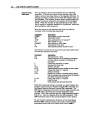
You can enable the Stop-on-Stall function with the FSDI
command. The move will terminate. without any delay. as
soon as a stall is detected This function works either in Motor
Step or Encoder Step mode.
CAUTION
DIsabIlDg the Stop-Gn-StaD function with the FSD(l)
command wID allow the AX to 8nIsh the move regard1e88 of a
stan detection, even if the load 18 jammed. Thls can
potentla11y damage user equipment.
The FSD 1 command is valid only if the Enable Stall
Detection (FSB 1) command has been issued.
The Stop-on-Stall function depends on the setting for
backlash (set with the DW command) to give optimum
operation. The factory default setting for backlash is 0 motor
steps. If you mount the encoder on the motor, you should
leave this parameter set to zero for the most accmate
response.
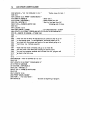
Command
DW1 " "
ER4"""
FSH1
FSD1
pescrjption
Sets backlash value to 100 steps.
Sets encoder resolution to 4,000 steps/rev.
Enables stall detect.
Enables stop on stall.
Stall detection does not occur until the error exceeds the dead
band backlash (set with the DW command). Consequently. if
the indexer does not see an encoder pulse after moving the
motor 100 steps. the AX. will detect a stall and stop the motor
immediately.
58
AX DRIVE USER GUIDE
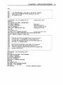
Determining
Backlash
You can measure the actual backlash with the following
procedure. The idea is to move in one direction, stop, and
make a series of one-step moves in the opposite direction. No
change in encoder position occurs while the indexer takes up
the backlash. The number of motor steps counted before any
encoder counts are received is the measure of the backlash.
NOTE: When the en.ccxier is mounted directly to the motor,
this is mainly a magnetic backlash (or hysteresis), othenvise.
gear backlash is also measured.
Move the motor in one direction and clear the position
counters with the following commands.
Command
FSB0
MN
A10
V1
06400
G
PZ
Description
Sets indexer to motor step mode
Sets Mode normal
Sets acceleration to 10 revslsec 2
Sets velocity to 1 rps
Sets distance to 6400 steps
Executes the move (Go)
Sets absolute pOSition counter to zero
Now execute a series of one-step moves and report both motor
and encoder position each time:
Command
01
PS
L
G
1LF
1PR
T1.0
1LF
1PX
T1.0
N
C
Description
Sets distance to 1 step
Pauses execution of the following commands
until the indexer receives the Continue (C)
command
Causes the sequence to repeat
Executes the move (Go)
Sends a line feed
Reports absolute motor position in motor steps
Pauses the motor for 1 second
Sends a line feed
Reports the number of encoder pulses (steps)
that the encoder has received since the Position
Zero (PZ) command was issued
Pauses the motor for 1 second
Ends the loop
Clears pause and executes the move
While this command string is running, you may compare the
position reports from the Position Report (PR) command and
the Report Absolute Encoder POSition (PX) command. The
IPR report represents the number of motor steps traveled, and
the IPX report represents the number of encoder steps
traveled. When the response from the IPX command changes
from 0 to I, note the response from the IPR command. This
IPR command report is the actual backlash of your system.
To use the AX's stall detection function, set the Dead Band
Window (DW) command equal to the value of the backlash
determined above and then Enable Stall Detect (FSH1).
CHAPTER 4. APPLICATION DESIGN
Output-On-
Stall
59
You can select the Output-on-Stall function with the Turn on
Output # 1 on Stall Detect (FSE) command. This is useful for
signaling other components in your system that a stall has
occurred.
If you enter the FSE 1 command. the AX programmable Output
# 1 goes on (current flows) when a stall is detected and remains
on untn a new move begins. ThIs command is valid only jf
the Stall Detection has been enabled (FSB 1), and jf the AX is
set to Encoder Step Mode (FSB1).
Command
MN
FSB1
OW10
FSH1
FS01
FSE1
A2
V.1
012800
G
Description
Sets the system in the preset mode
Enables encoder mode
Selects backlash to be 10 motor steps
Enables stall detect function
Stops motor if a stall is detected
Turns on Output 1 if stall is detected
Sets acceleration to 2 revs/sec 2
Sets velocity to 0.1 rps
Sets distance to 12,800 encoder steps
Execute the move (Go)
While the motor is moving. you can cause a stall by holding
the shaft. If you can not manually stall the motor, you can
Simulate a stall by carefully disconnecting the +5V encoder
lead from pin # 1 on the AX encoder connector. When the stall
occurs, Output 1 Is turned on and the motor stops (this signals
you that the motor has stalled). The motor will come to a stop.
Multi-Axis
Stop
On a multi-axis AX system, you may wish to have all axes
stop motion jf a stall is detected on any axis. You can select
this function via the Kill Motion on Trigger 3 (FSF) command.
When selected with the FSFI command, a signal on the
Trigger 3 input terminates the move immediately, thus
functioning as a remote stop input.
Follow the following steps to set up your AX system to
terminate the multi-axis moves when a stall is detected on
any axis:
1. Set the first AX unit to Turn on Output 1 on Stall (FSE1)
2. Connect Output 1 (pin 15) on the first AX unit to Trigger 3
(pin 11) on all the other AX units in the daisy-chain.
60
AX DRIVE USER GUIDE
Output on
Position
Loss
The Turn on Output #2 When Within Dead Band (FSG)
command allows the AX to signal other system components
when the motor ts within the dead band. Thts command is
valid only if Stall Detection (FSH1) has been enabled: it will
have no effect otherwise.
At the end of the move, if the motor is within the specif1ed
dead band (DB), Output #2 wUl be turned on.
Command
MN
FS81
FSCl
0810
FSHl
FSGl
A2
V5
0500
G
Description
Sets the system in the preset mode
Sets indexer to encoder step mode
Enables position maintenance
Selects dead band at 10 encoder steps
(Position Maintenance is activated if the motor's
end-of-move position is off by more than 10
encoder steps.)
Enables stall detect function
Turns on Output 2 if the motor's end-of-move
position is within the 10 encoder step dead band
range
Sets acceleration to 2 revslsec 2
Sets velocity to 5 rps
Sets distance to 500 steps
Execute the move (Go)
CHAPTER 4. APPLICATION DESIGN
61
Program Control
Triggers
You can use the Wait for Trigger (TR) conunand to specify a
configuration of trigger conditions to be matched before
executing a sequence of buffered commands. The trigger
inputs are lRIG 1. lRIG 2. and lRIG 3. The three pOSSible
conditions you can specify are as follows:
•
•
•
1 =Wait for the trigger input to be high (no current flows)
0 = Wait for the trigger input to be low (current flows)
X =Ignore the trigger input
Command
MN
A2
V5
025600
TR01X
G
pescription
Sets u nit to Preset mode
Sets acceleration to 2 revs/sec 2
Sets velocity to 5 rps
Sets distance to 25,600 steps
Waits for Trigger Input 1 to turn on and Trigger
Input 2 to turn off (ignores Trigger Input 3)
Executes 4,OOO-step move (Go)
The move will not be executed until current flows on the TRIG 1 input
and no current flows on the TRIG 2 input.
The TS command is useful for checking the status of the
trigger inputs when it appears as though execution is being
halted by the TR command and all conditions for matching
the trigger input configuration defined by the TR command
appear to be met. It may also be used to initiate external
actions by monitoring the trigger inputs manually with a
computer controlling the AX.
Delays
You can use the Time Delay (T) command to halt the operation
of the indexer function for a preset time. If you are in the
Continuous Mode (MC)' you may use the Continous Time
(CTM) conunand to run the motor at continuous velOCity for a
set time. then change to a different velocity.
In the Preset mode (MN). the motor finishes the move before
the indexer executes the time delay.
Command
PS
A7
V6
025600
G
T5.0
H
G
C
pescription
Waits for the AX to receive a Continue (C)
command before executing next command
Sets acceleration to 7 revs/sec 2
Sets velocity to 6 rps
Sets distance to 25,600 steps
Moves motor 25,600 steps
Waits 5 seconds after the move ends
Changes motor direction
Moves motor 25,600 steps in the OPPOSite
direction
Cancels Pause and executes the move
62
AX DRIVE USER GUIDE
LoopS
Single Loops
This section discusses methods of establishing loops in the
programs you write for you application. Loops can be created
individually or nested within each other.
You may use the Loop (L) command to repeat certain programs
the one provided below. All the commands between the L
command and the N command are looped (repeated) the
number of times indicated in the L command. You can use the
Immediate Pause (01 command to temporarily halt execution
of the loop while it is in progress. NarE: 'I11e U command
does not work in continuous mode. To resume loop execution.
issue the Continue (C) command.
Command
PS
MPI
MN
AS
VS
LS
0128""
G
T2.0
N
C
Description
Pauses command execution until the indexer
receives a Continue (C) command
Sets mode to incremental
Sets move to normal mode
Sets acceleration to 5 revs/sec 2
Sets velocity to 5 rps
Performs the Loop 5 times
Sets distance to 12,800 steps
Executes the move (Go)
Delays 2 seconds after the move
Ends Loop
Initiates command execution
The motor moves a total of 64.000 steps (a succession of five
12.800-step moves with a 2-second pause between each move).
Nested
Loops
The example below shows how you can nest a sma11loop
inside a major loop. The only way you can nest a loop is by
using the Constant Velocity Loop (CL) and End Loop (CN)
commands in the continuous mode (MC). You may nest a
constant velocity loop within a standard loop. but not within
another CL loop. The following sequence turns on output 1.
then output 2. then turns then both off. You can issue the Stop
Loop (Y) command to terminate both loops.
Command
P
MC
V1
L10
CL5
C01X
CTM1
COX1
CV2
CO,,"
CV1
CN
CV"
G
H
N
C
Description
Pauses execution until C command
Sets move to continuous mode
Sets velocity to 1 rps
Loops 10 times - - - - - - - - - - - ,
Constant velocity loop 5 times
Tums on output 1
Waits 1 second
Tums on output 2
Nested
Changes velocity to 2 rps
Loop
Outer
Tums off both outputs
Loop
Changes velocity to 1 rps
Ends continuous velocity nested loop
Changes velocity to 0 (stop)
Executes move
Changes direction
Ends outer Ioop _ _ _ _ _ _ _ _ _~
---""I
Cancels pause and executes move
CHAPTER 4. APPLICATION DESIGN
POSs
(Programmable
Output Bits)
You can turn the programmable output bits (our 1 and our 2)
on and off using the Output (0) command. You can use the
outputs to signal remote controllers. tum on LEOs. sound
bU72ers, etc. A one (1) turns on a given output, a zero (0) turns
the output off. and an X leaves the output unchanged. The
outputs conduct current when they are on and do not conduct
when they are off (see the 0 command description in Chapter
5. Software Reference).
Command
MN
PS
A1"
V5
0384""
0"1
G
OX"
C
Move
Completion
Signal
Description
Set move to Mode Normal
Pauses execution until indexer receives a
Continue (C) command
Sets acceleration to 10 revs/sec2
Sets velocity to 5 revs/sec
Sets move distance to 38,400 steps
Sets programmable output 1 off and output 2 on
Executes the move (Go)
After the move ends, leaves output 1
unchanged and sets output 2 off
Cancels the Pause and executes the move
When you complete a move, you may use the AX's
programming capabllity to Signal the end of the current move.
In a preset move, you may use one of the following commands:
• LF
• CR
• ..o
•
Example #1
63
Command
PS
MN
A2
V2
0384""
G
1LF
C
Line feed (see example #1)
Carriage return (see example #2)
Output command (see example #3)
Quote command (see example #4)
Description
Pauses execution until indexer receives a
Continue (C) command
Sets move to normal mode
Sets acceleration to 2 revs/sec 2
Sets velocity to 2 rps
Sets distance to 38,400 steps
Executes the move (Go)
Sends a line feed over the RS-232C interface
Cancels the Pause and executes the move
The motor moves 38,400 steps. When you complete the move,
the unit issues a line feed from the AX to the host over the RS232C interface.
Example #2
Command
PS
MN
A2
V2
0384""
G
1CR
Description
Pauses execution until indexer receives a
Continue (C) command
Sets move to normal mode
Sets acceleration to 2 revslsec 2
Sets velocity to 2 rps
Sets distance to 38,400 steps
Executes the move (Go)
Sends a carriage return
C
Cancels the Pause and executes the move
The motor moves 38.400 steps. When the AX completes the
move, it issues a carriage return to the host over the RS-232C
interface.
64
AX DRIVE USER GUIDE
Example '3
Command
PS
MN
A2
V2
D384""
G
01X
C
Qescription
Pauses execution until indexer receives a
Continue (C) command
Sets move to normal mode
Sets acceleration to 2 revs/sec2
Sets velocity to 2 rps
Sets distance to 38,400 steps
Executes the move (Go)
Turns on Output 1
Cancels the Pause and executes the move
The motor moves 38.400 steps. When the AX completes the
move. Output 1 is turned on.
Example #4
Command
PS
MN
A2
V2
D384""
G
"DONE
C
Description
Pauses execution until indexer receives a
Continue (C) command
Sets move to normal mode
Sets acceleration to 2 revs/sec 2
Sets velocity to 2 rps
Sets distance to 38,400 steps
Executes the move (Go)
Sends the message, DONE, to the terminal
Cancels the Pause and executes the move
The motor moves 38,400 steps. When you complete the move,
the AX issues the DONE message to the host over the RS-232C
interface.
Sequences
Sequence
Programming
A sequence is a series of commands. These commands are
executed in their programmed order whenever the sequence is
run. Immediate conunands cannot be stored in a sequence.
just as they cannot be stored in the conunand buffer. Only
buffered commands may be used in a sequence.
The AX has 2,000 bytes of non-volatile memory (EEPROM) to
store up to 7 sequences. Each sequence may have up to 256
characters (including delimiters). Note that one sequence
cannot borrow any unused portion of another sequence's
allocated memory. Use the following commands to define,
erase, and run sequences:
Command
XD
XE
XP
XQ
XR
X RP
Xl
XU
XZ
Description
Starts sequence definition
Deletes sequence from EEPROM
Sets Power-up Sequence Mode
Sets/resets interrupted Run mode
Runs a sequence
Runs a sequence with a pause
Ends sequence definition
Uploads sequence
Sets power-up sequence to zero
The cOTTUTlands that you enter to define a sequence are
presented vertically in the examples below. This was done to
help you read and. understand the commands. When you are
actually typing these commands into your terminal, they will
be displayed horizontally.
CHAPTER 4. APPLICATION DESIGN
65
It Is a good practise to erase the sequence with the XE
command before defining the sequence with the XD
command. To begin the definition of a sequence. enter the XD
command immediately followed by sequence identifier
number (1 to 7) and a delimiter (pressing the space bar or the
carriage return key). The XT command ends the sequence
definition and automatically loads the sequence into the AX's
EEPROM. All commands entered after the XD command and
before the XT conunand are executed when the sequence Is
run. An example Is provided below.
Command
XE1
X01
MN
A2
V1"
0128""
G
H
G
Xl
XR1
pescription
Erases Sequence 1
Begins definition of sequence 1
Sets move to normal mode
Sets acceleration to 2 revs/sec2
Sets velocity to 10 rps
Sets distance to 12,800 steps
Executes the move (Go)
Reverses direction
Executes the move (Go)
Ends definition of sequence 1
Runs Sequence 1
Once you define a sequence. it cannot be redefined until you
delete it. You can delete a sequence from EEPROM by entering
the XE command immediately followed by a sequence
identifier (1 to 7) and a delimiter. You may then redefine that
sequence into EEPROM. You can issue the Sequence Status
Definition (XSD) command (preceded by a device address) to
verify if the last sequence definition was successful. The
possible responses seen on your terminal are 0, 1. or 2. A 0
means the sequence was successfully defined. A 1 means the
sequence already exists with the number you have specified.
A 2 means there was not enough space in the sequence buffer
for that sequence.
To check the status of a sequence. issue the Sequence Status
(XSS) command. This command must be preceded by a device
address and followed immediately by the number (1 to 7) of
the sequence and a delimiter. The possible responses are 0
(Empty). 1 (Bad checksum), or 3 (O.K.).
If you wish to check the contents of a sequence. enter the XU
command. For example, issuing the lXUl command causes
the AX to send the contents of sequence number 1 to the
computer terminal's screen. The 1 preceding the XU command
Is the device address which must be present since the XU
command Is a device-specific command. We are assuming in
this example that the AX Is set up at device address 1.
Sequence
Selection
After you define the sequences over the RS-232C interface, you
can execute the sequences by using one of the following modes
of operation:
•
•
•
Stand-alone Operation
Host Computer Operation
Programmable Logic Controller (PLC) Operation
66
AX DRIVE USER GUIDE
Stand-alone
Operation
Power-up
Sequence
Execution
This section explains and provides examples of how to store
sequences to be automatically executed when you power-up
the system. or executed by remote switches. You will first
have to define the sequences into the AX non-volatile
memory. You will need a computer or PLC with RS-232C
communication capabUities for programming the AX .
A single. pre-defined sequence may be executed on power-up
by issuing the XP command immediately followed by a
sequence identifier number (1 to 7) and a delimiter. For
example. if an XPI command was entered. sequence #1 would
be executed the next time the AX was powered up. Sequence # 1
would continue to execute on each subsequent power-up until
you issue an XZ command or a new XP(o-9) conunand. Once
the pre-defined sequence is finished executing. the AX returns
control to the RS-232C communications port. If no sequence
had been defined as Sequence 1. control would automatically
go to the RS-232C communications port.
The XP command may be issued at any time. except during
sequence definition. Once an XP command is entered. it is
automatically saved in the AX's non-volatile memory.
To determine which. if any. sequence will be executed on
power-up. issue the Sequence Status Power-up (XSP)
command.
Using Remote
Sequence
Inputs
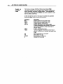
One method of executing sequences is performed by issuing
the XP9 command. The XP9 command will not cause any
sequence to be immediately executed. Once you issue the XP9
command. the AX reads the sequence select inputs (Pins 12-14
on AX I/O connector) every time it is powered-up, or every
time the Z (software reset) command is issued. The status of
the sequence select inputs will be interpreted by the AX as a
sequence number (see Table 4-2). If. at the time of power up,
the number represented by the sequence select inputs is a
valid pre-defined sequence (numbers 1 to 7). the AX will
automatically execute that sequence. When this first
sequence is finished executing. the AX will once again read the
sequence select inputs and execute the next valid sequence
number present on these inputs. The AX will continue to
execute sequences in this fashion until you issue an S (stop) or
a K (kill) command. or if an end-of- travel limit is
encountered. If the AX reads the number 8. or any number
that has no sequence defined. it will wait until the status of
the inputs changes to a valid. pre-defined sequence.
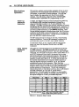
Sequence
SEa 1
SEa 2
SEa 3
1
2
3
ON
OFF
ON
OFF
ON
OFF
ON
OFF
ON
ON
OFF
OFF
ON
ON
OFF
OFF
ON
ON
ON
ON
OFF
OFF
OFF
OFF
4
5
6
7
8*
* Non-valid sequence
OFF - open switch (not pulled to ground)
ON - closed switch (Dulled to around)
Table 4-2. Sequence Select Inputs
CHAPTER 4. APPLICATION DESIGN
67
When in the XP9 mode, it is possible to cause the AX to pause
between sequence execution. This is done with the XQl
command. When the XQl command is present within a
sequence, the AX will pause after the execution of the sequence
and will wait for all sequence select inputs to be OFF (see
sequence #8 in Table 4-2). The AX will then read the status of
the sequence select inputs and execute the corresponding
sequence number. This interrupted run mode will continue
until you issue the XQ0 command.
You can also program the AX to read the sequence select lines
on power-up with the XPS command. This command will
cause the AX to execute the first vaUd sequence number it
reads on the sequence select inputs after power-up (exactly
Uke the XP9 command). It differs from the XP9 command in
that it returns control to the RS-232C communications port
after it finishes executing the first sequence, rather than
reading the sequence select lines again and executing another
sequence.
Sample
Applications
and
Commands
STEP 1
STEP
2
The following are step-by-step procedures demonstrating how
to run sequences. Using a tenninal or a computer, key in the
following commands:
Issue the XP9 corrunand.
Define the following sequences:
Command
XE6
X06
MN
A1
V20
012800
G
XT
Command
XE7
X07
MN
A1
V20
0-44800
G
XT
STEP
3
STEP 4
pescription
Erases Sequence 6
Defines Sequence 6
Sets move to normal mode
Sets acceleration to 1 rev/sec 2
Set velocity to 20 rps
Sets distance to 12,800 steps
Executes the move (Go)
Ends Sequence 6 definition
pescription
Erases Sequence 7
Defines Sequence 7
Sets move to normal mode
Sets acceleration to 1 rev/sec 2
Set velocity to 20 rps
Sets distance to 44,800 steps (CCW)
Executes the move (Go)
Ends Sequence 7 definition
Verify that your programs were stored properly by uploading
each entered sequence (XU followed by the number of the
sequence). If you receive responses that differ from what you
programmed, re-enter those sequences.
Make sure all the sequence select inputs are ofT (not grounded).
68
AX DRIVE USER GUIDE
STEP
5
Cycle Power or enter the Z command. The AX will go through
the nonnal XP9 mode operation. In XP9 mode, the AX scans
the sequence select inputs, looking for a valid sequence
according to the binary value of the three inputs (see Table 42).
STEP
6
Momentarily tum on (ground) the SEQ 2 input. This will
execute sequence number 6. NarE: After the sequence has
finished executing, the inputs are again scanned to execute
another sequence.
STEP
7
Host Computer
Operation
Momentarily tum on (ground) the SEQ 1 input. This will
execute sequence number 7.
This section assumes you have successfully communicated
with the AX. If you have not verified that your RS-232C
communications link is functioning properly. return to
Chapter 2. Getting Started. and complete this check before
attempting to complete this section.
IBM-compatible software diskette prOViding terminal
emulation is available from Parker Compumotor. To operate
the software. you will need BASICA or GW BASIC
programming language programs installed in your computer.
An
Immediate
Sequence
Execution
You can execute a sequence by entering the XR connnand
immediately followed by a sequence identifier number (1 to 7)
and a delimiter. The sequence will be executed immediately
after the delimiter.
You can issue the Sequence Status Run (XSR) command to
verify if the last sequence you issued was executed
successfully. The possible responses are as follows:
•
•
fJ
Non-Zero
1
2
3
4
Running
Not running:
In a loop
Invalid sequence
Erased
Bad checksum
CHAPTER 4. APPLICATION DESIGN
Single-Axis
Control
Single-Axis
Interface
Program
Example
The AX system is capable of single and multiple axis
applications. The principles developed for a single-axis
system apply as well to multi-axis systems.
If you already have BASICA or GW BASIC programming
languages on your computer, you may use the following
sample program designed to open a serial communication
port and send and receive AX commands. The program
performs the following steps:
•
Executes the first move upon user input
•
Watts for a line feed from the AX , which indicates the end
of the move.
•
Upon user input, executes the second move
•
Watts for a line feed from the AX, which indicates the end
of the move. It then begins the process again.
This application can be looked on as moving a part out,
machining the part, then bringing the part back.
1'
2'
3'
4
5
6
7
8
'
'
'
'
'
69
AX. BAS PROGRAM
*********.******** •••• **.****** ••• ***** ••• ******************
*
* This program controls the RS232 Communication line to execute 2
* different moves using the AX
*
*
*
*
****.********************** ••• ** •• **.********.* ••••• ***.****
15 OPEN "COM1 :9600,N,8, 1,RS,CS,DS,CD" AS #1
' Open Communication port
20 V$ = "": 0$ = "": ECHO$ = "": LF$ = "":
' Initialize variables
90 CLS
100 LOCATE 12,15
105 PRINT" PRESS ANY KEY TO START THE PROGRAM"
' Wait for input from user
107 V$ = INKEY$: IF LEN(V$) = 0 THEN 100
120 Z$ = "Z"
'.Reset the AX indexer
122 PRINT #1,Z$;
124 0$ = INPUT$(2,1)
900 '
**************** ••• ***.*.***** •• **** •••••••• *.****** •• ****
901 ' *
902
Line 1000-1060 sends a move down to the first AX. Computer
*
903 ' * waits for the Une Feed from the AX indicating that the motor
904 ' * has finished its move. Computer will not command second AX to move
*
905
*
906 ' *
*
* • • • ** ** * *• ** * * * ** *• * *• • • • • • * * • • • • • • • * * * • * • • • * • * • • • • • * * * *•
AX DRIVE USER GUIDE
70
, Define move for Axis 1
1000 MOVE1$ = "1A1 1V2 1025,600 1G 1LF"
1005 CLS
1007 LOCATE 12,15: PRINT" DOING MOVE 1 "
, Move axis 1.
1010 PRINT #1,MOVE1$
, Read echoes from AX
1015 ECHO$ = INPUT$(23,1)
, Wait for line feed from AX
1020 LF$ = INPUT$(l, 1)
, indicating end of move.
1040 IF LF$ <> CHR$(10) OOTO 1020
1045 CLS
1047 LOCATE 12,15
1050 PRINT "MOVE 1 DONE"
, Let user know axis 1 is done
1060 LOCATE 15,15: PRINT" PRESS ANY KEY TO GO ON TO SECOND MOVE"
1070 V$ = INKEY$: IF LEN(V$) = 0 THEN 1060
1900 ' ...... • .. * * * * * * * * * * * * * * • ............ * * ................ * .. * .. * ................
1901
1902
1903
1904
1905
1906
1907
1908
1909
1910
1911
1912
'
'
'
'
'
..
..
..
..
..
After axis one is done, we request that you press any key to go on
to the second move. In real application, we would expect you to
go ahead with the process and work on the part before going on to
next move. (i.e. Activate a punch)
,
,
,
,
..
..
..
..
Now that first move is finished, we go on to move #2.
AX also prints a line feed after finishing the second move.
As soon as computer receives the line feed from AX, program will
go back to the first move.
' ..
* ............ ..
*
..
..
..
* ...................... * .. * .................................... * .......................................... ..
2000 MOVE2$ = "A 10 V5 0-64000 G H G 1LF"
2005 CLS
2007 LOCATE 12,15: PRINT" DOING MOVE 2"
2010 PRINT #l,MOVE2$
2015 ECHO$ = INPUT$(25,1)
2020 LF$ = INPUT$(l, 1)
2040 IF LF$ <> CHR$(10) GOTO 2020
2045 CLS
2047 LOCATE 12,15
2050 PRINT "MOVE 2 DONE"
2060 FOR I = 1 TO 1000: NEXT I
2070 GOTO 20
, Go back to beginning of program.
CHAPTER 4. APPLICATION DESIGN
71
Multi-Axis
Device-specific commands require that a device address
Control
precede them. The AX will not execute a devtce-speciflc
command if there is no device address preceding the
command. or if the device address setting in the AX does not
match the address preceding the command. Universal
commands do not require device identifiers preceding them.
A universal command with no device address will be executed
regardless of the address setting of the AX. If a device address
does precede a universal command. it will only be executed by
an AX set to that particular address.
The E (Enable RS-232 communication) and F (Disable RS-232
communication) commands are useful in a daisy chain for
locking out particular indexers from responding to universal
commands with no preceding device address.
NOTE: The F command. will keep the AXfrom executing any
commands (except the E command) sent to it over the RS-232C
interface. but will not prevent the commandJrom being
echoed.
For Example. to lock-out the AX unit set to device address 1. so
that universal commands are only executed by the AX's set to
address 2 and 3. the following step is perfonned:
•
Send the IF command over the RS-232C communication
line. locking out the AX at device address 1.
All universal commands (with no preceding device address)
will now be executed only by the AX's at Device addresses 2
and 3. Entering a 2F command in addition to IF command
would allow only the AX at device address 3 to execute
universal commands with no preceding device address. This
ellminates the need to precede every command intended for a
specific AX (in this case. the AX at device address 3) with a
device address. Sending an E command over the RS-232C line
will re-enable all drives previously disabled with the F
command. Preceding the E command with a device address
will re-enable only the AX set to that particular device
address.
When using the XU command to upload the contents of a
specified sequence from an AX in a daisy-chain. it is
necessary to disable all the drives in the chain that come after
the drive being queried with the F command (as described
above). This will prevent subsequent drives from executing
the commands being sent back to the tenninal. See the XU
command description in Chapter 5. Software Reference.
For daisy-chain wiring instructions. refer to Chapter 2.
Getting Started.
AX DRIVE USER GUIDE
72
Sample
Application
and
Commands
Example: Three indexers are on an RS-232C daisy chain.
Send the following commands:
Command
MN
AS
V1"
1 064""
20128""
3D 192""
G
Description
Sets unit to Preset mode
Sets acceleration to 5 revs/sec2 for all three
indexers
Sets velocity to 10 rps for all three indexers
Sets Axis 1 distance to 6,400 steps
Sets Axis 2 distance to 12,800 steps
Sets Axis 3 distance to 19,200 steps
Moves all axes.
Unit 1 moves 6.400 steps, unit 2 moves 12.800 steps. and unit 3
moves 19.200 steps. All three units use the same acceleration
and velocity rates. Units 1. 2. and 3 will start at about the
same time (2mS apart. due to a propagation delay of 2
characters over the RS-232C interface).
Multi-Axis
Interface
Program
Example
1'
2'
3'
The following program is very similar to AX.BAS. except this
program controls 2 AX's on a daisy chain. This program
assumes the device address of 2 AXs to be 1 and 2 respectively.
The program does the following:
•
Executes the first move upon user input
•
Waits for a line feed from the LX drive. which indicates the
end of the move.
•
Upon user input. executes the second move on axis 2
•
Waits for a line feed from the second AX. which indicates
the end of the move. It then begins the process again.
AX2.BAS PROGRAM
* * * * * * * * * * * . * * * * ••• ******* ••• * . * * • • • • ****** •• ***************
4 ' *
5 ' * This program controls the RS232 Communication line to execute 2
'
6 ' * different moves using 2 AX units..
7 ' *
*
B' *
* * * • .. * * * • • * • .. * • * * * * * * * * • * * • • • .. • .. • * .. * • * * * * * * * * • * • • * * * * * * * * * • •
15 OPEN "COM1 :9600,N,B,l,RS,CS,DS,CD" AS #1
' Open Communication port
20 V$ = "": 0$ = "": ECHO$ = "-: LF$ = --:
' Initialize variables
90 CLS
100 LOCATE 12,15
105 PRINT" PRESS ANY KEY TO START THE PROGRAM"
• Wait for input from user
107 V$ = INKEY$: IF LEN(V$) = 0 THEN 100
120 Z$ = "Z , Reset the AX indexer
122 PRINT #l,Z$;
124 0$ = INPUT$(2,1)
CHAPTER 4. APPLICATION DESIGN
900 '
********************* ••••• ******** ••••••••••••••••••••••••
901
902
903 '
904
905 '
906 '
.
..
.
Line 1000-1060 sends a move down to the first AX. Computer
waits for the Line Feed from the AX indicating that the motor
has finished its move.
..
.
if
• • • • • • * •••• ****.********** •••• ***.***.** ••• **************.
, Define move for Axis 1
1000 MOVE1$ = "lAl lV2 1025,600 lG lLF"
1005 CLS
1007 LOCATE 12,15: PRINT" MOVING AXIS 1 "
1010 PRINT #l,MOVE1$
, Move axis 1.
1015 ECHO$ = INPUT$(22,l)
, Read echoes from AX
1020 LF$ = INPUT$( 1, 1)
• Wait for line feed from AX
1040 IF LF$ <> CHR$(10) GOTO 1020
• indicating end of move.
1045 CLS
1047 LOCATE 12,15
1050 PRINT "AXIS 1 FINISHED ITS MOVE"
, Let user know axis 1 done
1060 LOCATE 15,15: PRINT" PRESS ANY KEY TO MOVE SECOND AXIS"
1070 V$ = INKEY$: IF LEN(V$) = 0 THEN 1060
1900 . .. ... • ...... * ........ * .. * • .... * * .... • .. * .. • .......... * ...... * ........ * .... * .. * .... * * * * * ......
1901
1902
1903
1904
1905
1906
1907
1908
1909
1910
1911
1912
•
'
•
'
..
..
..
..
After axis one is done, we request that you hit any key to go on
to second move. In real application, we would expect you to
go ahead with the process and work on the part before going on to
next move. (Le. Activate a punch)
'
'
'
'
..
..
..
..
Now that first axis finished its move, we go on to move axis 2.
Second AX also prints a line feed after finishing the move.
As soon as computer receives the line feed from AX, program will
go back to the first move.
..
..
• ...................... * * * .......... * * .. * .. * .. * * * .................. * .......... * .. * .. * ........ * .... ..
2000 MOVE2$ = "2A 1 2V2 206,400 2G 2LF "
2005 CLS
2007 LOCATE 12,15: PRINT" AXIS 2 MOVING "
2010 PRINT #l,MOVE2$
2015 ECHO$ = INPUT$(22,1)
2020 LF$ = INPUT$(l, 1)
2040 IF LF$ <> CHR$(10) GOTO 2020
2045 CLS
2047 LOCATE 12,15
2050 PRINT "AXIS 2 FINISHED ITS MOVE"
2060 FOR I = 1 TO 1000: NEXT I
2070 GOTO 20
' Go back to beginning of program.
73
74
AX DRIVE USER GUIDE
PLe Operation
PLC
Connections
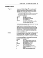
You can use a PLC to execute 7 different sequences that are
stored in the AX non-volatile memory. Three outputs from
the PLC can be used to execute sequences, and two inputs to the
PLC can be used to monitor AX outputs.
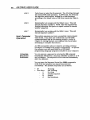
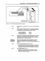
Assuming your PLC accepts open-emitter outputs, connect the
inputs and outputs as shown in Figure 4-4. If not, contact a
Compumotor Applications Engineer at (800) 358-9070.
!·i·:99t~Yi:i> ~~---{
;OUTPGT2C·1---.
. . . •:.• .
:.
·i·!:!6tifIDt~i=
:."L!
~ !(lj: ;.: : :!.:!. SSEE 2
:): : : : : : : : : : :
:.i:.i::::.:.
Q1
·:::.::.:
.. ..
..::.·.;:i..;.:·.:.:1:':::·.··
... :i... ..:!.:·.:!:.:I :I:.:I
... ...
Q
i i!i i: ,~ uj.i?· · : :· · I- ....~.__-t:.!.I.I.·.:..i.I~.rzl ~~~
:-: .. ;. .. ;. ..;... ;. ..... .;.;- ... ;:;:;::;::...
::.:::·.:.'.11.1..11.1.1.1.
~~
1---~~
.......--t::I. II:!~!I·!I. :I;
OUT2
&;.;;.;....;.;..-..;.;..-......._..;.;.;..1
PLC
AX 110 CONNECTOR
(Pins 12 - 16)
Figure 4-4. PLC Connections
Scanning for
Sequence
Execution
Changing the BCD values of sequence input lines results in a
new sequence being run that corresponds to the new value. As
indicated in Table 4-2, the configuration of the values issued
determines which sequence the indexer will run. For
example, turning on SEQ2 and SEQ3 and turning off SEQ 1
executes Sequence 2.
Issuing the XP8 or the XP9 conunands causes the AX to scan
the sequence select inputs and execute the fist valid sequence
it encounters (on power-up). When in XP8 mode, the AX
returns control to the RS-232C port after executing the first
valid sequence. When in the XP9 mode. the AX will continue
scanning inputs and executing valid sequences until you issue
an S or a K command.
When you issue the XP command identifying sequences 1 - 7,
this over-rides the sequence input configuration used when
you issue the XP8 and the XP9 commands.
The Scan (SN) command determines how long the sequence
select input must be maintained before the indexer executes
the program. This is a debounce time.
CHAPTER 4. APPLICATION DESIGN
Sample
Applications
and
Commands
75
This section provides step-by-step procedures to run
sequences from your PtC. First. you need to enter the
programs into the AX drive. You will need a terminal or a
computer with RS-232C communication capability. You need
to define the sequences before you can execute them with your
PLC's BCD outputs.
Using a terminal or a computer. key in the following
commands:
STEP 1
STEP
2
Issue the XP9 command.
Define the following sequences:
Command
XE1
X01
MN
A1
V10
06400
G
XT
Command
XE2
X02
MN
A1
V10
03200
G
XT
Command
XE3
XD3
MN
A1
V10
012800
G
XT
Command
XE4
MN
X04
A1
V10
0·44800
G
XT
STEP
3
Description
Erases Sequence 1
Defines Sequence 1
Sets move to normal mode
Sets acceleration to 1 rev/sec 2
Set velocity to 10 rps
Sets distance to 6,400 steps
Executes the move (Go)
Ends Sequence 1 definition
Description
Erases Sequence 2
Defines Sequence 2
Sets move to normal mode
Sets acceleration to 1 rev/sec 2
Set velocity to 10 rps
Sets distance to 3,200 steps
Executes the move (Go)
Ends Sequence 2 definition
Description
Erases Sequence 3
Defines Sequence 3
Sets move to normal mode
Sets acceleration to 1 rev/sec 2
Set velocity to 10 rps
Sets distance to 12,800 steps
Executes the move (Go)
Ends Sequence 3 definition
Description
Erases Sequence 4
Sets move to normal mode
Defines Sequence 4
Sets acceleration to 1 rev/sec 2
Set velocity to 10 rps
Sets distance to 44,800 steps (CCW)
Executes the move (Go)
Ends Sequence 4 definition
Verify that your programs were stored properly by uploading
each entered sequence (XU command preceded by the device
address and followed by the number of the sequence). If you
receive responses that differ from what you programmed. reenter those sequences.
76
AX DRIVE USER GUIDE
4
Cycle Power or enter the Z command. The AX will go through
the nonnal XP9 mode operation. In XP9 mode, the AX scans
the sequence select inputs and selects and executes the first
avallable valid sequence according to the binaIy value of the
three inputs (see Table 4-2). After the sequence is executed, the
inputs are again scanned to execute another sequence. The AX
will continue to execute sequence in this fashion until you
issue an S or a K command, or if an end-of-travellimit is
encountered.
STEP 4
To run sequence #1, ground sequence inputs 1,2, and 3 at the
same time (refer to table 4-2 for sequence input configurations
to run other sequences).
STEP
ModeJ 72
(ThumbwheeJ)
Operation
The Model 72 and Model 72-1/0 units interface with the AX
Drive via an RS-232C interface. The Model 72 provides
adjustable thumbwheel Switches to enter and change AX
motion control parameters. These switches allow you to set
and modify velocity, acceleration, distance, direction, dwell
time, loop count, and other parameters.
If you wish to purchase a Model 72 or Model 72-1/0, contact
your Automated Technology Center or Compumotor
Distributor. The Model 72 User Guide contains all pertinent
information for use with the AX.
Tuning Procedure
NOTE: For most applications. tuning an AX Drive to a motor
is not necessary.
Should certain aspects of the systems performance come
under scrutiny in the area of velocity ripple, resonant
frequencies or step-to-step accuracy, the follOwing procedure
could offer improved performance.
Velocity ripple is a term used to express a variance of angular
speed. It is usually expressed as a percentage of the
commanded velOCity. This is due to the mechanical
inaccuracies of the motor resulting in unequal step sizes. It
can also be enhanced by running the motor at its' natural
freq1,lency causing resonance. Adding solid inertia to the
system can shift or modify the phenomenon but does little to
eliminate it. If your system can handle more inertia, conSider
using viscous dampers.
A 10: 1 load to rotor inertia ratio is the maximum value
recommended.
To a certain extent, adding friction to the system can actually
dampen the effects of both resonance and velocity ripple.
CHAPTER 4. APPLICATION DESIGN
77
The recommended system frictional load for a step motor is
approximately 5% of the motor's maximum torque
capability. For motor specifications and speed/torque curves,
refer to Chapter 6, Hardware Reference.
The step-to-step accuracy of the step motor should not be
confused with the motors absolute accuracy. Absolute
accuracy is based on the quality of the mechanical
construction of the motor. This means that tuning of an
open-loop stepper motor and drive will not improve this spec.
On the other hand, the drive electrOnics are responsible for
adjusting current in the two phases of the motor which create
the m1crosteps found between each 1.80 full motor step. The
amount of distance each step can vary is referred to as the
step-to-step accuracy of the system and it may be possible to
improve this by tuning.
The motor should be tuned to its drive while under nonnal
loaded conditions. Tuning prior to this is useless since
changes in the load or the system's transmission will result in
a new natural frequency for the motor.
Tuning the drive affects the profile of current being sent to the
motor. You will need to re-tune the drive if the current setting
switches are changed. Refer to Chapter 6 for valid settings for
DIP switches 1 through 5.
Controlling
motor
velocity
When using the AX Drive, the built-in indexer will solve this
problem. Using an RS-232C communications device, place
the AX in Mode Continuous (MC) and use the Acceleration (A)
and the Velocity (V) commands to get the motor moving, then
vary the velocity using the Immediate Velocity (VC) command.
Command
G
Description
Set to Mode continuous
Set acceleration to 10 rev/sec
Set velocity to 1 rev/sec
Execute the move (Go)
VC2
Set immediate velocity to 2 rev/sec
VC.s
Set immediate velocity to .5 rev/sec
MC
A10
V1
78
AX DRIVE USER GUIDE
Gauging
Motor
Resonance
Selecting a method of gauging motor resonance can be
accomplished in a number of ways;
TACHOMETER
METHOD
Using an oscilloscope to look at the output of a tachometer
attached to the motor shaft. The tachometer will output a DC
voltage, proportional to speed. This voltage will oscillate
around an average voltage when the motor is resonating. The
amplitude of this oscillation will be at a maximum when the
natural frequency of the motor is located. USing this method
your goal is to tune for the lowest oscillation amplitude.
SOUNDING
BOARD METHOD
When practicing your tuning skills, an unloaded motor can be
placed on a sounding board or a table. When a velocity is
commanded which is near the motors natural frequency, the
phenomenon will cause Vibration which will become audible.
Using this method your goals is to tune for the lease amount of
vibration.
STETHOSCOPE
METHOD
When tuning under loaded conditions the audible vibration
caused by the motors natural frequency can be heard by
placing the tip of a screw drive against the motor casing and
holding the handle of the screw driver close to your ear (as you
would a stethoscope). This will also allow you to hear the
different magnitudes of vibration caused by the motors
natural frequency. USing this method your goal is to tune for
the least amount of Vibration.
TOUCH METHOD
After some experience with tuning, it is possible to locate a
motor's natural frequency by simply placing your fingertips
on the motor shaft and adjusting the motor velocity. Once the
Critical velocity is located, tuning for maximum smoothness
can be done in the same way.
CAUTION
Exercise extreme caution whenever you are near any moving
part of a mechan1cal system. Also, be wary of touching the
motor, as it is very hot during normal operating conditions.
To tune the drive you will need a small non-conductive screw
driver.
Locate the
natural
frequency of
the System
STEP 1
STEP
2
Before you can tune the drive to its motor, you will need to
locate the natural frequency of the motor and its load. This
can be accomplished using the following procedure:
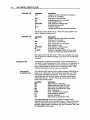
Let the motor and driver wann up for 30 minutes to an hour.
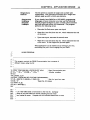
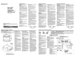
Locate the tuning pots on the drive you are uSing. Figure 4-5
below shows the location of the AX Drive tuning pots. Note
that the small metal plate held in place with two screws must
be removed to reveal the tuning pots.
CHAPTER 4. APPLICATION DESIGN
79
Tuning Pot "lusting .crewe
AX Series Drive
Figure 4-5. AX DIP Switch and Tuning Pot Locations
STEP
3
STEP 4
Position all four tuning pots to the center of their adjustment
range.
Start the motor moving at one of the velocities shown below.
depending on the motor frame size. These velocities should
get you close to the natural frequency of the motor.
57 Series (NEMA 23)
83 Series (NEMA 32)
106 Series (NEMA 42)
STEP
5
Adjusting
the Drive to
the Motor
STEP
1
3.6rps
2.8 rps
2.0 rps
USing one of the gauging methods mentioned above. increase
and decrease the velocity in small increments (. 1 rps and
lower) until you have located the velocity where the natural
frequency seems to be most prominent.
Now that you have located the natural frequency of your
system. the following procedure will adjust the current
waveform of the drive to the mechanical characteristics of the
system.
Adjust the current trim if necessary (pot #1)
The current trim pot allows you to select a current setting
that lies between any two dip switch settings. In most
applications. adjustment of this setting is not necessary.
STEP
2
Adjust phase balance (pot #4).
Adjust this pot for maximum smoothness. This pot
adjusts the amplitude of current in phase B to within
±10% of the current in Phase A
80
AX DRIVE USER GUIDE
STEP
Adjust phase B offset (pot #2) and phase A offset (pot #3).
3
Alternately adjust these two pots for maximum
smoothness as well. These pots adjust the zero (0) crossing
point of the current in each phase.
STEP
Re-Iocate the natural frequency again.
4
Increase and decrease the velocity in small increments (.1
rps and lower) until you have re-Iocated the velocity where
the natural frequency seems to be most prominent.
STEP
Repeat steps 1 through 4 untU you have maxlm1zed the
motor's performance.
5
Selecting a
new Wave
Shape
All the above adjustments have affected only the total amount
of current being sent to the motor and the amount in each
phase of the motor with respect to each other. This can be
very effective in most applications. but it may be possible to
take your tuning procedure one step further by changing the
shape of the current wavefonn itself. See Table 4-3.
Waveform
#1
#2
#3
#4
#5
#6
#7
#8
#9
% of 3rd
Harmonic
-8%
-6%
-4%
-2%
0%
+2%
+4%
+6%
+8%
Table 4-3. AX Waveform Settings
WAVE SHAPING
FOR THE AX
DRIVE
STEP
1
Stop motion to the motor.
STEP
2
Use the WV (Select Micro-stepping Waveform) command to
select a new waveform. The new waveform will take effect
immediately. There are 9 different waveforms avaUable and
waveform #5 is the default setting.
STEP
3
Re-Iocate the natural frequency again.
STEP
4
Repeat the section titled Adjusting the DrIver to the Motor
STEP
5
Repeat steps 1 through 3 in this section untU maximum
performance is achieved.
STEP
6
Once you have chosen the new waveform. you will need to
command the new value evety time you power up or the
command can be made part of a non-volatile memoty
sequence that is executed on power up.