1
TM
RackSwitch G8124
Command Reference
Version 1.0
Part Number: BMD00076, January 2009
2350 Mission College Blvd.
Suite 600
Santa Clara, CA 95054
www.bladenetwork.net
RackSwitch G8124 Command Reference
Copyright © 2009 Blade Network Technologies, Inc., 2350 Mission College Blvd., Suite 600, Santa Clara,
California, 95054, USA. All rights reserved. Part Number: BMD00076.
This document is protected by copyright and distributed under licenses restricting its use, copying,
distribution, and decompilation. No part of this document may be reproduced in any form by any means
without prior written authorization of Blade Network Technologies, Inc. Documentation is provided “as
is” without warranty of any kind, either express or implied, including any kind of implied or express
warranty of non-infringement or the implied warranties of merchantability or fitness for a particular
purpose.
U.S. Government End Users: This document is provided with a “commercial item” as defined by FAR
2.101 (Oct. 1995) and contains “commercial technical data” and “commercial software documentation” as
those terms are used in FAR 12.211-12.212 (Oct. 1995). Government End Users are authorized to use this
documentation only in accordance with those rights and restrictions set forth herein, consistent with FAR
12.211- 12.212 (Oct. 1995), DFARS 227.7202 (JUN 1995) and DFARS 252.227-7015 (Nov. 1995).
Blade Network Technologies, Inc. reserves the right to change any products described herein at any time,
and without notice. Blade Network Technologies, Inc. assumes no responsibility or liability arising from
the use of products described herein, except as expressly agreed to in writing by Blade Network
Technologies, Inc. The use and purchase of this product does not convey a license under any patent rights,
trademark rights, or any other intellectual property rights of Blade Network Technologies, Inc.
Originated in the USA.
RackSwitch is a trademark of Blade Network Technologies, Inc. in the United States and certain other
countries. Cisco® and EtherChannel® are registered trademarks of Cisco Systems, Inc. in the United States
and certain other countries. Any other trademarks appearing in this manual are owned by their respective
companies.
2
BMD00076, January 2009
RackSwitch G8124 Command Reference
Contents
Preface 9
Who Should Use This Book 10
How This Book Is Organized 11
Typographic Conventions 12
How to Get Help 14
ISCLI Basics 15
ISCLI Command Modes 15
Global Commands 18
Command Line Interface Shortcuts 20
Command Abbreviation 20
Tab Completion 20
User Access Levels 21
Idle Timeout 22
Information Commands 23
System Information 25
SNMPv3 System Information 26
SNMPv3 User-based Security Model User Table Information 28
SNMPv3 View Table Information 29
SNMPv3 Access Table Information 30
SNMPv3 Group Table Information 31
SNMPv3 Community Table Information 31
SNMPv3 Target Address Table Information 33
SNMPv3 Target Parameters Table Information 34
SNMPv3 Target Parameters Table Index Information 35
SNMPv3 Notify Table Information 36
SNMPv3 Dump Information 37
General System Information 38
Show Syslog Messages 39
User Status 40
Layer 2 Information 41
Forwarding Database Information 43
Show All FDB Information 44
MAC Notification Status 45
Clearing Entries From the Forwarding Database 45
BMD00076, January 2009
3
RackSwitch G8124 Command Reference
Link Aggregation Control Protocol Information 46
Link Aggregation Control Protocol 46
Spanning Tree Information 48
Common Internal Spanning Tree Information 51
Trunk Group Information 53
Trunk Group 54
VLAN Information 55
IGMP Multicast Group Information 56
IGMP Group Information 57
IGMP Multicast Router Information 58
QoS Information 59
QoS DSCP Information 60
Access Control List Information 61
Access Control List Information 61
RMON Information 65
RMON History Information 65
RMON Alarm Information 66
RMON Event Information 67
Port Information 68
Interface Link Information 70
Interface Transceivers 71
Information Dump 71
Statistics Commands 73
Port Statistics 74
Bridging Statistics 76
Ethernet Statistics 77
Interface Statistics 80
LACP Statistics 82
Link Statistics 83
Layer 2 Statistics 84
Forwarding Database Statistics 85
Layer 3 Statistics 86
IGMP Statistics 87
ICMP Statistics 88
TCP Statistics 90
UDP Statistics 91
ACL Statistics 93
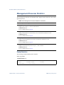
Management Processor Statistics 94
Packet Statistics 94
TCP Statistics 95
4
BMD00076, January 2009
RackSwitch G8124 Command Reference
UDP Statistics 96
CPU Statistics 97
SNMP Statistics 98
RMON Statistics 102
Statistics Dump 103
Statistics Dump Output Example 103
Configuration Commands 105
Viewing and Saving Changes 107
Saving the Configuration 107
System Configuration 108
System Host Log Configuration 110
SSH Server Configuration 111
RADIUS Server Configuration 112
TACACS+ Server Configuration 113
NTP Server Configuration 115
System SNMP Configuration 116
SNMPv3 Configuration 118
User Security Model Configuration 120
SNMPv3 View Configuration 121
View-Based Access Control Model Configuration 122
SNMPv3 Group Configuration 123
SNMPv3 Community Table Configuration 124
SNMPv3 Target Address Table Configuration 125
SNMPv3 Target Parameters Table Configuration 126
SNMPv3 Notify Table Configuration 127
System Access Configuration 128
HTTPS Access Configuration 129
User Access Control Configuration 130
System User ID Configuration 131
Port Configuration 132
Port Link Configuration 134
Port FDB Configuration 135
Temporarily Disabling a Port 135
Port ACL Configuration 136
Layer 2 Configuration 137
FDB Configuration 138
Static FDB Configuration 138
Multiple Spanning Tree Protocol Configuration 139
Common Internal Spanning Tree Configuration 141
BMD00076, January 2009
5
RackSwitch G8124 Command Reference
Spanning Tree Configuration 145
Bridge Spanning Tree Configuration 146
Spanning Tree Port Configuration 148
Trunk Configuration 150
IP Trunk Hash Configuration 151
Link Aggregation Control Protocol Configuration 152
LACP Port Configuration 153
VLAN Configuration 154
Private VLAN Configuration 155
Layer 3 Configuration 156
IP Interface Configuration 157
Default Gateway Configuration 158
IGMP Configuration 158
IGMP Snooping Configuration 159
IGMPv3 Configuration 160
IGMP Static Multicast Router Configuration 161
Domain Name System Configuration 162
Quality of Service Configuration 163
802.1p Configuration 163
DSCP Configuration 163
ACL Configuration 164
ACL Overview 164
Media Access Control Extended ACL Configuration 166
IP Standard ACL Configuration 169
IP Extended ACL Configuration 170
TCP ACL Configuration 170
UDP ACL Configuration 172
Internet Protocol ACL Configuration 174
OSPF ACL Configuration 175
PIM ACL Configuration 176
Numeric Protocol ACL Configuration 177
ICMP ACL Configuration 178
Port Mirroring 180
Uplink Failure Detection Configuration 181
Failure Detection Pair Configuration 182
Link to Monitor Configuration 182
Link to Disable Configuration 183
RMON Configuration 184
RMON Statistics Configuration 184
RMON History Configuration 185
RMON Alarm Configuration 186
6
BMD00076, January 2009
RackSwitch G8124 Command Reference
RMON Event Configuration 188
Configuration Dump 189
Saving the Active Switch Configuration 189
Restoring the Active Switch Configuration 189
Show Active and Backup Configuration 190
Active Configuration command output 190
Operations Commands 191
Operations-Level Port Options 192
Boot Options 193
Updating the Switch Software Image 195
Loading new Software to Your Switch 196
Selecting a Software Image to run 197
Uploading a Software Image From Your Switch 197
Selecting a Configuration Block 198
Resetting the Switch 198
Using the Boot Management menu 199
Using SNMP with Switch Images and
Configuration Files 200
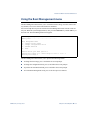
Loading a new switch image 201
Loading a switch configuration to the active configuration 201
Saving the switch configuration from the active
configuration 202
Maintenance Commands 203
Forwarding Database Maintenance 205
Debugging Commands 206
IGMP Group Information 207
IGMP Multicast Routers Maintenance 208
Index 209
BMD00076, January 2009
7
RackSwitch G8124 Command Reference
8
BMD00076, January 2009
Preface
The RackSwitch G8124 Command Reference describes how to configure and use the software
with your switch. This guide lists each command, together with the complete syntax and a
functional description, using the IS Command Line Interface (ISCLI).
For documentation about installing the switch physically, see the RackSwitch G8124
Installation Guide.
BMD00076, January 2009
9
RackSwitch G8124 Command Reference
Who Should Use This Book
This Command Reference is intended for network installers and system administrators engaged
in configuring and maintaining a network. The administrator should be familiar with Ethernet
concepts, IP addressing, the IEEE 802.1D Spanning Tree Protocol, and SNMP configuration
parameters.
10 Preface
BMD00076, January 2009
RackSwitch G8124 Command Reference
How This Book Is Organized
Chapter 1 “ISCLI Basics,” describes how to connect to the switch and access the information
and configuration commands. This chapter provides an overview of the command syntax,
including command modes, global commands, and shortcuts.
Chapter 2 “Information Commands,” shows how to view switch configuration parameters.
Chapter 3 “Statistics Commands,” shows how to view switch performance statistics.
Chapter 4 “Configuration Commands,” shows how to configure switch system parameters,
ports, VLANs, Jumbo Frames, Spanning Tree Protocol, SNMP, Port Mirroring, IP Routing,
Port Trunking, and more.
Chapter 5 “Operations Commands,” shows how to use commands which affect switch performance immediately, but do not alter permanent switch configurations (such as temporarily
disabling ports). The commands describe how to activate or deactivate optional software features.
Chapter 6 “Boot Options,” describes the use of the primary and alternate switch images, how
to load a new software image, and how to reset the software to factory defaults.
Chapter 7 “Maintenance Commands,” shows how to generate and access a dump of critical
switch state information, how to clear it, and how to clear part or all of the forwarding database.
“Index” includes pointers to the description of the key words used throughout the book.
BMD00076, January 2009
Preface 11
RackSwitch G8124 Command Reference
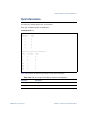
Typographic Conventions
The following table describes the typographic styles used in this book.
Table 1 Typographic Conventions
Typeface or Symbol
Meaning
angle brackets < >
Indicate a variable to enter based on the description inside the brackets.
Do not type the brackets when entering the command.
Example: If the command syntax is
ping <IP address>
you enter
ping 192.32.10.12
12 Preface
bold body text
Indicates objects such as window names, dialog box names, and icons, as
well as user interface objects such as buttons, and tabs.
bold Courier text
Indicates command names, options, and text that you must enter.
Example: Use the show ip arp command.
braces { }
Indicate required elements in syntax descriptions where there is more
than one option. You must choose only one of the options. Do not type
the braces when entering the command.
Example: If the command syntax is
show portchannel {<1-12>|hash|information}
you enter:
show portchannel <1-12>
or
show portchannel hash
or
show portchannel information
brackets [ ]
Indicate optional elements in syntax descriptions. Do not type the brackets when entering the command.
Example: If the command syntax is
copy running config tftp [data-port|mgt-port]
you enter
copy running config tftp
or
copy running config tftp data-port
or
copy running config tftp mgt-port
italic text
Indicates variables in command syntax descriptions. Also indicates new
terms and book titles.
Example: If the command syntax is
show spanning-tree stp <1-128>
<1-128> represents a number between 1-128.
BMD00076, January 2009
RackSwitch G8124 Command Reference
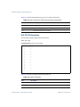
Table 1 Typographic Conventions
Typeface or Symbol
Meaning
plain Courier text
Indicates command syntax and system output, for example, prompts and
system messages.
Example: configure terminal
|
Separates choices for command keywords and arguments. Enter only one
of the choices. Do not type the vertical line when entering the command.
Example: If the command syntax is
show portchannel {<1-12>|hash|information}
you must enter:
show portchannel <1-12>
or
show portchannel hash
or
show portchannel information
vertical line
BMD00076, January 2009
Preface 13
RackSwitch G8124 Command Reference
How to Get Help
If you need help, service, or technical assistance, call Blade Network Technologies Technical
Support:
US toll free calls: 1-800-414-5268
International calls: 1-408-834-7871
You also can visit our web site at the following address:
http://www.bladenetwork.net
Click the Support tab.
The warranty card received with your product provides details for contacting a customer
support representative. If you are unable to locate this information, please contact your reseller.
Before you call, prepare the following information:
14 Preface
Serial number of the switch unit
Software release version number
Brief description of the problem and the steps you have already taken
Technical support dump information (# show tech-support)
BMD00076, January 2009
CHAPTER 1
ISCLI Basics
Your switch is ready to perform basic switching functions right out of the box. Some of the
more advanced features, however, require some administrative configuration before they can
be used effectively.
This guide describes the individual ISCLI commands available for the switch.
The ISCLI provides a direct method for collecting switch information and performing switch
configuration. Using a basic terminal, the ISCLI allows you to view information and statistics
about the switch, and to perform any necessary configuration.
This chapter explains how to access the IS Command Line Interface (ISCLI) for the switch.
ISCLI Command Modes
The ISCLI has three major command modes, listed in order of increasing privileges,
as follows:
User EXEC mode
This is the initial mode of access. By default, password checking is disabled for this mode,
on console.
Privileged EXEC mode
This mode is accessed from User EXEC mode. A password is required to enter Privileged
EXEC mode. The default password is enable. Enter disable to turn off privileged
commands.
Global Configuration mode
This mode allows you to make changes to the running configuration. If you save the configuration, the settings survive a reload of the switch. Several sub-modes can be accessed
from the Global Configuration mode. For more details, see Table 1-1 on page 16.
BMD00076, January 2009
15
RackSwitch G8124 Command Reference
Each mode provides a specific set of commands. The command set of a higher-privilege mode
is a superset of a lower-privilege mode — all lower-privilege mode commands are accessible
when using a higher-privilege mode. Table 1-1 lists the ISCLI command modes.
Table 1-1 ISCLI Command Modes
Command Mode/Prompt
Command used to enter or exit
User EXEC
Default mode, entered automatically on console.
Exit: exit or logout
G8124>
Privileged EXEC
G8124#
Global
Configuration
G8124(config)#
Interface IP
Configuration
G8124(config-ip-if)#
Interface Port
Configuration
G8124(config-if)#
Portchannel
Configuration
G8124(config-if)#
Enter Privileged EXEC mode, from User EXEC mode:
enable
Exit to User EXEC mode: disable
Quit ISCLI: exit or logout
Enter Global Configuration mode, from Privileged EXEC
mode:
configure terminal
Exit to Privileged EXEC: end or exit
Enter Interface IP Configuration mode, from Global Configuration mode:
interface ip 1
Exit to Global Configuration mode: exit
Exit to Privileged EXEC mode: end
Enter Port Configuration mode from Global Configuration mode:
interface port <port alias or number>
Exit to Global Configuration mode: exit
Exit to Privileged EXEC mode: end
Enter Portchannel Configuration mode from Global Configuration mode:
portchannel <trunk group number>
Exit to Global Configuration mode: exit
Exit to Privileged EXEC mode: end
ACL IP Standard Access List Con- Enter the Access Control List (ACL) IP Standard Configuration
figuration
mode.
access-list ip <128-256> standard
G8124 (config-std-nacl)#
Exit to Global Configuration mode: exit
Exit to Privileged EXEC mode: end
ACL IP Extended Access List
Configuration
G8124 (config-ext-nacl)#
16 Chapter 1: ISCLI Basics
Enter the Access Control List (ACL) IP Extended Configuration
mode.
access-list ip <128-256> extended
Exit to Global Configuration mode: exit
Exit to Privileged EXEC mode: end
BMD00076, January 2009
RackSwitch G8124 Command Reference
Table 1-1 ISCLI Command Modes
Command Mode/Prompt
Command used to enter or exit
ACL MAC Configuration
G8124 (config-ext-macl)#
Enter the Access Control List (ACL) IP MAC Extended Configuration mode.
access-list mac extended <1-127>
Exit to Global Configuration mode: exit
Exit to Privileged EXEC mode: end
VLAN
Configuration
Enter VLAN Configuration mode, from Global Configuration
mode:
vlan <1-4094>
Exit to Global Configuration mode: exit
Exit to Privileged EXEC mode: end
G8124(config-vlan)#
BMD00076, January 2009
Chapter 1: ISCLI Basics 17
RackSwitch G8124 Command Reference
Global Commands
Some basic commands are recognized throughout the ISCLI command modes. These commands are useful for obtaining online Help, navigating through the interface, and for saving
configuration changes.
For help about a specific command, type the command, followed by ? (question mark).
Table 1-2 Description of Global Commands
Command
Action
?
Help may be requested at any point in a command by entering a question
mark ( ? ). If nothing matches, the Help list will be empty and you must
backup until entering a '?' shows the available options.
Two styles of Help are provided:
1. Full Help is available when you are ready to enter a command argument
(e.g. 'show ? ') and describes each possible argument.
2. Partial Help is provided when an abbreviated argument is entered and you
want to know what arguments match the input (e.g. 'show pr?'.)
clear
Clears statistical and log information. For example, enter clear ntp to
clear all NTP statistics. Enter clear ? to view a list of commands.
console-log
Enables or disables console logging for the current session.
copy
Transfers files or writes configuration changes.
default
Resets a parameter to its default setting. For example, enter default
access telnet port to reset the Telnet port to its default setting. Enter
default ? to view a list of default commands.
exit
Go up one level in the command mode structure.
Exit from the command line interface and log out.
no
Negates the argument. For example, if you enabled the logging console feature, and you want to disable it at a later time, enter no logging console to disable the logging console feature. Enter no ? to view a list of
arguments that you can use with the no command.
ping
Use this command to verify station-to-station connectivity across the network. The format is as follows:
ping <host name>|<IP address> [tries (1-32)> [delay]]
Where IP address is the hostname or IP address of the device, tries (optional)
is the number of attempts (1-32), delay (optional) is the number of seconds
between attempts. The DNS parameters must be configured if specifying
hostnames.
18 Chapter 1: ISCLI Basics
BMD00076, January 2009
RackSwitch G8124 Command Reference
Table 1-2 Description of Global Commands
Command
Action
[no] prompting
Enables or disables CLI prompts. Prompts allow you to step through complex configurations, and provide supporting information. You can disable
prompting to facilitate CLI scripting.
The default value is enabled.
show history
This command brings up the history of the last 10 commands.
show who
Displays a list of users who are currently logged in. For more information,
see “User Status” on page 40.
traceroute
Use this command to identify the route used for station-to-station connectivity across the network. The format is as follows:
traceroute <host name>| <IP address> [<max-hops (1-32)>
[delay]]
Where IP address is the hostname or IP address of the target station, maxhops (optional) is the maximum distance to trace (1-32 devices), and delay
(optional) is the number of seconds for wait for the response. The DNS
parameters must be configured if specifying hostnames.
BMD00076, January 2009
Chapter 1: ISCLI Basics 19
RackSwitch G8124 Command Reference
Command Line Interface Shortcuts
Command Abbreviation
Most commands can be abbreviated by entering the first characters which distinguish the command from the others in the same mode. For example, consider the following full command
and a valid abbreviation:
G8124(config)# spanning-tree stp 2 bridge hello 2
or
G8124 (config)# sp stp 2 br h 2
Tab Completion
By entering the first characters of a command at any prompt and pressing <Tab>, if only one
command fits the input text when <Tab> is pressed, that command is supplied on the command line, waiting to be entered.
For example, if you enter the following partial command, followed by the tab key, the system
attempts to complete the command:
G8124(config)# show span <Tab>
G8124(config)# show spanning-tree
20 Chapter 1: ISCLI Basics
BMD00076, January 2009
RackSwitch G8124 Command Reference
User Access Levels
To enable better switch management and user accountability, three levels or classes of user
access have been implemented on the switch. Levels of access to CLI, Web management
functions, and screens increase as needed to perform various switch management tasks.
Conceptually, access classes are defined as follows:
user: Interaction with the switch is completely passive—nothing can be changed on the
switch. Users may display information that has no security or privacy implications, such as
switch statistics and current operational state information.
oper: Interaction with the switch is completely passive—nothing can be changed on the
switch. Users can display information that has no security or privacy implications, such as
switch statistics and current operational state information. Users who have an ID with oper
privileges can make operational changes, such as running operational-level commands to
disable an interface.
admin: Administrators are the only ones that may make permanent changes to the switch
configuration—changes that are persistent across a reboot/reset of the switch. Administrators can access switch functions to configure and troubleshoot problems on the switch.
Because administrators can also make temporary (operator-level) changes as well, they
must be aware of the interactions between temporary and permanent changes.
Access to switch functions is controlled through the use of unique user names and passwords.
After you connect to the switch via local Telnet, remote Telnet, SSH, or Browser Based Interface (BBI) session, you must enter a password. The default user names/password for each
access level are listed in the following table.
NOTE – It is recommended that you change default switch passwords after initial configuration
and as regularly as required under your network security policies.
BMD00076, January 2009
Chapter 1: ISCLI Basics 21
RackSwitch G8124 Command Reference
Table 1-3 User Access Levels
User Account
Description and Tasks Performed
Password
User
The User has no direct responsibility for switch management.
He or she can view all switch status information and statistics,
but cannot make any configuration changes to the switch.
user
Operator
Interaction with the switch is completely passive—nothing can
be changed on the switch. Users can display information that
has no security or privacy implications, such as switch statistics
and current operational state information. Users who have an
ID with oper privileges can make operational changes, such as
running operational-level commands to disable an interface.
Administrator
The superuser Administrator has complete access to all comadmin
mand modes, information, and configuration commands on the
switch, including the ability to change both the user and administrator passwords.
NOTE – With the exception of the “admin” user, access to each user level can be disabled by
setting the password to an empty value.
Idle Timeout
By default, the switch will disconnect your Telnet session after five minutes of inactivity. This
function is controlled by the following command, which can be set from 1 to 60 minutes:
system idle <1-60>
Command mode: Global Configuration
22 Chapter 1: ISCLI Basics
BMD00076, January 2009
CHAPTER 2
Information Commands
This chapter explains how to use the Command Line Interface (CLI) to display switch
information.
Table 2-1 Information Commands
Command Syntax and Usage
show interface information
Displays port status information, including:
Port name, alias, and number
Whether the port uses VLAN Tagging or not
Edge status
FDB Learning status
Flooding of unknown destination MAC status
Port VLAN ID (PVID)
VLAN membership
To view an example of the command output, see page 68.
Command mode: All
show interface link
Displays configuration information about each port, including:
Port name, alias, and number
Port speed
Duplex mode (half, full, or auto)
Flow control for transmit and receive (no or yes)
Link status (up, down, or disabled)
Command mode: All except User Exec
To view an example of the command output, see page 70.
BMD00076, January 2009
23
RackSwitch G8124 Command Reference
Table 2-1 Information Commands
Command Syntax and Usage
show interface transceivers
Displays information about SFP/SFP+ transceivers. To view an example of the command output,
see page 71.
Command mode: All
show information-dump
Dumps all switch information available (10K or more, depending on your configuration).
If you want to capture dump data to a file, set your communication software on your workstation to
capture session data prior to issuing the dump commands.
Command mode: All
Note: This document does not contain an example of an information-dump because of space limitations.
24 Chapter 2: Information Commands
BMD00076, January 2009
RackSwitch G8124 Command Reference
System Information
The information provided by each command option is briefly described in Table 2-2, with links
to more detailed information.
Table 2-2 System Information Commands
Command Syntax and Usage
show sys-info
Displays system information, including:
System date and time
Switch up-time
Reason for last boot
MAC address
Software Version
PCBA Part Number
Serial Number
Manufacturing Date
Temperature sensor information
Fan speed RPMs
Status of each power supply
Command mode: All
To view an example of the command output, see page 38.
show logging messages
Displays syslog messages. To view an example of the command output, see page 39.
Command mode: All
clear logging
Clears syslog messages.
Command mode: All except User EXEC
show access user
Displays configured user names and their status.
Command mode: All except User EXEC
To view an example of the command output, see page 40.
show access user uid <1-10>
Displays details for the selected user ID.
Command mode: All except User EXEC
BMD00076, January 2009
Chapter 2: Information Commands 25
RackSwitch G8124 Command Reference
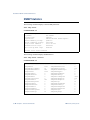
SNMPv3 System Information
SNMP version 3 (SNMPv3) is an extensible SNMP Framework that supplements the SNMPv2
framework by supporting the following:
A new SNMP message format
Security for messages
Access control
Remote configuration of SNMP parameters
See RFC2271 to RFC2276 for details about SNMPv3 architecture.
Table 2-3 SNMPv3 Commands
Command Syntax and Usage
show snmp-server v3 user
Displays User Security Model (USM) table information. The User-based Security Model (USM) in
SNMPv3 provides security services such as authentication and privacy of messages. This security
model makes use of a defined set of user identities displayed in the USM user table. To view an
example of the command output, see page 28.
Command mode: All
show snmp-server v3 view
Displays information about view, subtrees, mask and type of view. The user can control and restrict
the access allowed to a group to only a subset of the management information in the management
domain that the group can access within each context by specifying the group’s rights in terms of a
particular MIB view for security reasons. To view an example of the command output, see
page 28.
Command mode: All
show snmp-server v3 access
Displays View-based Access Control information. The access control subsystem provides authorization services. The vacmAccessTable maps a group name, security information, a context,
and a message type, which could be the read or write type of operation or notification into a MIB
view. The View-based Access Control Model defines a set of services that an application can use
for checking access rights of a group. This group’s access rights are determined by a read-view, a
write-view, and a notify-view. The read-view represents the set of object instances authorized for
the group while reading the objects. The write-view represents the set of object instances authorized for the group when writing objects. The notify-view represents the set of object instances
authorized for the group when sending a notification. To view an example of the command output,
see page 30.
Command mode: All
26 Chapter 2: Information Commands
BMD00076, January 2009
RackSwitch G8124 Command Reference
Table 2-3 SNMPv3 Commands
Command Syntax and Usage
show snmp-server v3 group
Displays information about the group that includes the security model, user name, and group
name. A group is a combination of security model and security name that defines the access rights
assigned to all the security names belonging to that group. The group is identified by a group
name. To view an example of the command output, see page 31.
Command mode: All
show snmp-server v3 community
Displays the community table information stored in the SNMP engine. To view an example of the
command output, see page 31.
Command mode: All
show snmp-server v3 target-address
Displays the Target Address table information. You can configure the target parameters entry and
store it in the target parameters table in the SNMP engine. This table contains parameters that are
used to generate a message. The parameters include the message processing model (for example:
SNMPv3, SNMPv2c, SNMPv1), the security model (for example: USM), the security name, and
the security level (noAuthnoPriv, authNoPriv, or authPriv). To view an example of the command
output, see page 33.
Command mode: All
show snmp-server v3 target-parameters
Displays the Target parameters table information. To view an example of the command output, see
page 34.
Command mode: All
show snmp-server v3 target-parameters <1-16>
Displays the current target parameters table information. To view an example of the command output, see page 34.
Command mode: All
show snmp-server v3 notify
Displays the notify table information. To view an example of the command output, see page 36.
Command mode: All
show snmp-server v3
Displays all the SNMPv3 information. To view an example of the command output, see page 37.
Command mode: All
BMD00076, January 2009
Chapter 2: Information Commands 27
RackSwitch G8124 Command Reference
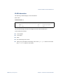
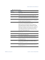
SNMPv3 User-based Security Model User Table Information
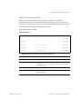
The User-based Security Model (USM) in SNMPv3 provides security services such as authentication and privacy of messages. The USM uses a defined set of user identities that are displayed in the USM user table. The following command displays SNMPv3 user information:
show snmp-server v3 user <1-16>
Command mode: All
The USM makes use of a defined set of user identities displayed in the USM user table.
The USM user table contains information, including:
The user name
A security name in the form of a string whose format is independent of the Security Model
An authentication protocol, which indicates that the messages sent on behalf of the user
can be authenticated
the privacy protocol
User Name
Protocol
---------------------------- -----------------------------adminmd5
HMAC_MD5
DES PRIVACY
adminsha
HMAC_SHA
DES PRIVACY
v1v2only
No Auth
NO PRIVACY
Table 2-4 USM User Table Information Parameters
Field
Description
User Name
This is a string that represents the name of the user that you can
use to access the switch.
Protocol
This indicates whether messages sent on behalf of this user are
protected from disclosure using a privacy protocol. The switch
supports DES algorithm for privacy. The switch also supports the
MD5 and HMAC-SHA Authentication algorithms.
28 Chapter 2: Information Commands
BMD00076, January 2009
RackSwitch G8124 Command Reference
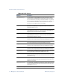
SNMPv3 View Table Information
Each user can control and restrict the access allowed to a group to a subset of the
management information in the management domain that the group can access within each
context, by specifying the group’s rights in terms of a particular MIB view for security reasons.
The following command displays the SNMPv3 View Table.
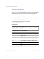
show snmp-server v3 view
Command mode: All
View Name
-----------------iso
Subtree
--------------------------1
Mask
-----
Type
-------Included
v1v2only
1
Included
v1v2only
1.3.6.1.6.3.15
Excluded
v1v2only
1.3.6.1.6.3.16
Excluded
v1v2only
1.3.6.1.6.3.18
Excluded
Table 2-5 SNMPv3 View Table Information Parameters
Field
Description
View Name
Displays the name of the view.
Subtree
Displays the MIB subtree as an OID string. A view subtree is the set
of all MIB object instances which have a common Object Identifier
prefix to their names.
Mask
Displays the bit mask.
Type
Displays whether a family of view subtrees is included or excluded
from the MIB view.
BMD00076, January 2009
Chapter 2: Information Commands 29
RackSwitch G8124 Command Reference
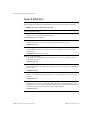
SNMPv3 Access Table Information
The access control subsystem provides authorization services.
The vacmAccessTable maps a group name, security information, a context, and a message
type, which could be the read or write type of operation or notification into a MIB view.
The View-based Access Control Model defines a set of services that an application can use to
check the access rights of a group. This group's access rights are determined by a read-view, a
write-view and a notify-view. The read-view represents the set of object instances authorized
for the group while reading the objects. The write-view represents the set of object instances
authorized for the group when writing objects. The notify-view represents the set of object
instances authorized for the group when sending a notification.
The following command displays SNMPv3 access information:
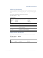
show snmp-server v3 access
Command mode: All
Group Name Model
Level
ReadV
WriteV
Notify
---------- ------- ------------ ----------- ---------- ---------v1v2grp
snmpv1
noAuthNoPriv iso
iso
v1v2only
admingrp
usm
AuthPriv
iso
iso
iso
Table 2-6 SNMPv3 Access Table Information
Field
Description
Group Name
Displays the name of group.
Model
Displays the security model used, for example, SNMPv1, or
SNMPv2 or USM.
Level
Displays the minimum level of security required to gain rights of
access. For example, noAuthNoPriv, authNoPriv, or authPriv.
ReadV
Displays the MIB view to which this entry authorizes the read
access.
WriteV
Displays the MIB view to which this entry authorizes the write
access.
NotifyV
Displays the Notify view to which this entry authorizes the notify
access.
30 Chapter 2: Information Commands
BMD00076, January 2009
RackSwitch G8124 Command Reference
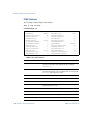
SNMPv3 Group Table Information
A group is a combination of security model and security name that defines the access rights
assigned to all the security names belonging to that group. The group is identified by a group
name.
The following command displays SNMPv3 group information:
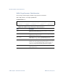
show snmp-server v3 group
Command mode: All
Sec Model
---------snmpv1
usm
usm
User Name
-----------------------------v1v2only
adminmd5
adminsha
Group Name
-------------------v1v2grp
admingrp
admingrp
Table 2-7 SNMPv3 Group Table Information Parameters
Field
Description
Sec Model
Displays the security model used, which is any one of: USM,
SNMPv1 and SNMPv2.
User Name
Displays the User Name for the group.
Group Name
Displays the access name of the group.
SNMPv3 Community Table Information
The following command displays SNMPv3 community information stored in the SNMP
engine:
show snmp-server v3 community
Command mode: All
Index
Name
User Name
Tag
---------- ---------- -------------------- --------trap1
public
v1v2only
v1v2trap
BMD00076, January 2009
Chapter 2: Information Commands 31
RackSwitch G8124 Command Reference
Table 2-8 SNMPv3 Community Table Parameters
Field
Description
Index
Displays the unique index value of a row in this table.
Name
Displays the community string, which represents the configuration.
User Name
Displays the User Security Model (USM) user name.
Tag
Displays the community tag. This tag specifies a set of transport
endpoints from which a command responder application accepts
management requests and to which a command responder application sends an SNMP trap.
32 Chapter 2: Information Commands
BMD00076, January 2009
RackSwitch G8124 Command Reference
SNMPv3 Target Address Table Information
The following command displays SNMPv3 target address information:
show snmp-server v3 target-address
Command mode: All
This command displays the SNMPv3 target address table information, which is stored in the
SNMP engine.
Name
---------trap1
Transport Addr
--------------47.81.25.66
Taglist
------v1v2trap
Params
---------v1v2param
Table 2-9 SNMPv3 Target Address Table Information Parameters
Field
Description
Name
Displays the locally arbitrary, but unique identifier associated with
this snmpTargetAddrEntry.
Transport Addr
Displays the transport addresses.
Taglist
This column contains a list of tag values which are used to select target addresses for a particular SNMP message.
Params
The value of this object identifies an entry in the snmpTargetParamsTable. The identified entry contains SNMP parameters to be used
when generating messages to be sent to this transport address.
BMD00076, January 2009
Chapter 2: Information Commands 33
RackSwitch G8124 Command Reference
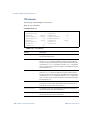
SNMPv3 Target Parameters Table Information
The following command displays SNMPv3 target parameters information:
show snmp-server v3 target-parameters
Command mode: All
Name
MP Model
--------------- -------v1v2param
snmpv2c
User Name
-------------v1v2only
Sec Model
--------snmpv1
Sec Level
--------noAuthNoPriv
Table 2-10 SNMPv3 Target Parameters Table Information
Field
Description
Name
Displays the locally arbitrary, but unique identifier associated with
this snmpTargeParamsEntry.
MP Model
Displays the Message Processing Model used when generating
SNMP messages using this entry.
User Name
Displays the securityName, which identifies the entry on whose
behalf SNMP messages will be generated using this entry.
Sec Model
Displays the security model used when generating SNMP messages
using this entry. The system may choose to return an inconsistentValue error if an attempt is made to set this variable to a
value for a security model which the system does not support.
Sec Level
Displays the level of security used when generating SNMP messages using this entry.
34 Chapter 2: Information Commands
BMD00076, January 2009
RackSwitch G8124 Command Reference
SNMPv3 Target Parameters Table Index Information
The following command displays SNMPv3 target parameters index information:
show snmp-server v3 target-parameters <1-16>
Command mode: All
name , mpmodel snmpv3
uname , model usm ,level noauthnoPriv
Table 2-11 SNMPv3 Target Parameters Table Index Information
Field
Description
Name
Displays the locally arbitrary, but unique identifier associated with
this snmpTargetParamsEntry.
mpmodel
Displays the Message Processing Model used when generating
SNMP messages using this entry.
uname
Displays the securityName, which identifies the entry on whose
behalf SNMP messages will be generated using this entry.
model usm
Displays the security model used when generating SNMP messages
using this entry. The system may choose to return an inconsistentValue error if an attempt is made to set this variable to a
value for a security model which the system does not support.
level
Displays the level of security used when generating SNMP messages using this entry.
BMD00076, January 2009
Chapter 2: Information Commands 35
RackSwitch G8124 Command Reference
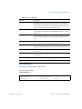
SNMPv3 Notify Table Information
The following command displays the SNMPv3 Notify Table:
show snmp-server v3 notify
Command mode: All
Name
Tag
-------------------- -------------------v1v2trap
v1v2trap
Table 2-12 SNMPv3 Notify Table Information
Field
Description
Name
The locally arbitrary, but unique identifier associated with this
snmpNotifyEntry.
Tag
This represents a single tag value which is used to select entries in
the snmpTargetAddrTable. Any entry in the snmpTargetAddrTable that contains a tag value equal to the value of this
entry, is selected. If this entry contains a value of zero length, no
entries are selected.
36 Chapter 2: Information Commands
BMD00076, January 2009
RackSwitch G8124 Command Reference
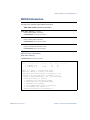
SNMPv3 Dump Information
The following command displays SNMPv3 information:
show snmp-server v3
Command mode: All
EngineId: 80.00.08.1c.04.46.53
usmUser Table:
User Name
Protocol
---------------------------- -----------------------------adminmd5
HMAC_MD5
DES PRIVACY
adminsha
HMAC_SHA
DES PRIVACY
v1v2only
No Auth
NO PRIVACY
vacmAccess Table:
Group Name
Model
Level
ReadV
WriteV
Notify
------------------------------------- ------------------v1v2grp
snmpv1
noAuthNoPriv iso
iso
v1v2only
admingrp
usm
AuthPriv
iso
iso
iso
vacmViewTreeFamily Table:
View Name
Subtree
Mask
Type
-------------------- -------------------------------- -------------- ----iso
1
Included
v1v2only
1
Included
v1v2only
1.3.6.1.6.3.15
Excluded
v1v2only
1.3.6.1.6.3.16
Excluded
...
BMD00076, January 2009
Chapter 2: Information Commands 37
RackSwitch G8124 Command Reference
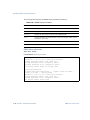
General System Information
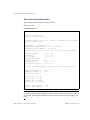
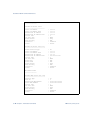
The following command displays system information:
show sys-info
Command mode: All
Blade Network Technologies Rack Switch G8124
System Information at
Thu Feb 02 21:04:11 2009
Switch has been up for 4 days, 15 hours, 36 minutes and 13 seconds
Last boot:(power cycle)
MAC Address: 00:17:ef:61:83:00
Management Port MAC Address: 00:22:00:7d:56:fe
Management Port IP Address: 127.16.2.54
Software Version 1.0.1, Boot Version 1.0.0.4, active config block
PCBA Part Number:
FAB Number:
Serial Number:
Manufacturing Date:
Hardware Revision:
Board Revision:
PLD Firmware version:
************
************
************
****
255
************
************
Fans are in Forward AirFlow, Warning at 85C and Failure at 100C
Temperature Sensor 1:
Temperature Sensor 2:
Temperature Sensor 3:
Speed
Speed
Speed
Speed
of
of
of
of
Fan
Fan
Fan
Fan
1:
2:
3:
4:
34.0 C
37.0 C
--.-
0 RPM
0 RPM
0 RPM
4224 RPM
State of Power Supply 1:
State of Power Supply 2:
On
Off
NOTE – The display of temperature will come up only if the temperature of any of the sensors
exceeds the temperature threshold. There will be a warning from the software if any of the sensors exceeds this temperature threshold. The switch will shut down if the power supply overheats.
38 Chapter 2: Information Commands
BMD00076, January 2009
RackSwitch G8124 Command Reference
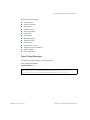
System information includes:
Switch up-time
Reason for last boot
MAC address
Software version
PCBA part number
FAB number
Serial number
Manufacturing date
Hardware revision
Board revision
PLD firmware revision
Temperature sensor information
Fan speed RPMs
Power supply status
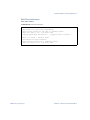
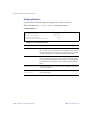
Show Syslog Messages
The following command displays system log messages:
show logging messages
Command mode: All
Jan 26 2008 18:03:27 RS G8124:CLI-ALERT:User (admin) logged in on console
Jan 26 2008 18:07:32 RS G8124:CFA-NOTICE:system: link up on port 20
Jan 26 2008 18:11:12 RS G8124:SYSTEM-CRITICAL:Warning: Fan Failure
BMD00076, January 2009
Chapter 2: Information Commands 39
RackSwitch G8124 Command Reference
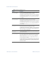
User Status
The following command displays the status of configured user names.
show access user
Command mode: All except User EXEC
Usernames:
admin - Always Enabled
user - enabled
oper - disabled
- online 3 sessions.
- offline
- offline
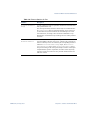
The following global command displays information about users who are logged in:
show who
Command mode: All except User EXEC
Line User
Peer-Address
COS
Login-Time Last-Cmd
==== ============= ===================== ===== ========== =======
tel admin
10.10.10.224:1735
admin 19:8:52
show who
The following information is provided for each current user:
Connection type
User name
User IP address
Class of Service
Time of login
Last command issued by the user
40 Chapter 2: Information Commands
BMD00076, January 2009
RackSwitch G8124 Command Reference
Layer 2 Information
Table 2-13 contains a summary of Layer 2 general information commands. The following sections describe detailed Layer 2 information commands.
Table 2-13 Layer 2 General Information Commands
Command Syntax and Usage
show spanning-tree
In addition to seeing if Spanning Tree is enabled or disabled, you can view the following STG
bridge information:
Priority
Hello interval
Maximum age value
Forwarding delay
You can also view the following port-specific STG information:
Port alias and priority
Cost
State
Command mode: All
show spanning-tree stp {<1-128>}
Displays information about a specific Spanning Tree Group. To view an example of the command
output, see page 48.
Command mode: All
show spanning-tree mstp cist information
Displays Common Internal Spanning Tree (CIST) bridge information, including the following:
Root bridge information and parameters
Priority
Hello interval
Maximum age value
Forwarding delay
You can also view port-specific CIST information, including the following:
Port number and priority
Cost
State
Link type
To view an example of the command output, see page 51.
Command mode: All
BMD00076, January 2009
Chapter 2: Information Commands 41
RackSwitch G8124 Command Reference
Table 2-13 Layer 2 General Information Commands
Command Syntax and Usage
show spanning-tree mstp mrst
Shows current Multiple Spanning Tree settings.
Command mode: All
show portchannel information
When trunk groups are configured, you can view the state of each port in the various trunk groups.
To view an example of the command output, see page 53.
Command mode: All
show vlan <1-4094>
Displays VLAN configuration information for all configured VLANs, including:
VLAN Number
VLAN Name
Status
Jumbo Frame usage
Port membership of the VLAN
Command mode: All
show private-vlan detail
Displays Private VLAN information.
Command mode: All
show ufd
Displays Uplink Failure Detection information.
Command mode: All
show layer2 information
Dumps all Layer 2 switch information available (10K or more, depending on your configuration).
If you want to capture dump data to a file, set your communication software on your workstation to
capture session data prior to issuing the dump commands.
Command mode: All
42 Chapter 2: Information Commands
BMD00076, January 2009
RackSwitch G8124 Command Reference
Forwarding Database Information
The Forwarding Database (FDB) contains information that maps the media access control
(MAC) address of each known device to the switch port where the device address was learned.
The FDB also shows which other ports have seen frames destined for a particular MAC
address.
NOTE – The master Forwarding Database supports up to 16K MAC address entries.
Table 2-14 FDB Information Commands
Command Syntax and Usage
show mac-address-table
Displays all entries in the Forwarding Database. To view an example of the command output, see
page 44.
Command mode: All
show mac-address-table address <MAC address>
Displays a single database entry by its MAC address. You are prompted to enter the MAC address
of the device. Enter the MAC address using the format, xx:xx:xx:xx:xx:xx. For example,
08:00:20:12:34:56
You can also enter the MAC address using the format, xxxxxxxxxxxx.
For example, 080020123456
Command mode: All
show mac-address-table port <port alias or number>
Displays all FDB entries for a particular port.
Command mode: All
show mac-address-table portchannel <trunk group number>
Displays all FDB entries for a particular trunk group.
Command mode: All
show mac-address-table state {forward|trunk|unknown}
Displays all FDB entries for a particular state.
Command mode: All
BMD00076, January 2009
Chapter 2: Information Commands 43
RackSwitch G8124 Command Reference
Table 2-14 FDB Information Commands
Command Syntax and Usage
show mac-address-table vlan <1-4094>
Displays all FDB entries on a single VLAN.
Command mode: All
show mac-address-table mac-notification
Displays the status of MAC notification for each port. To view an example of the command output,
see page 45.
Command mode: All
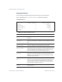
Show All FDB Information
The following command displays Forwarding Database information:
show mac-address-table
Command mode: All
Mac address Aging Time: 300
MAC address
----------------00:01:02:03:04:05
00:03:47:0a:54:19
00:07:e9:39:07:8a
00:08:74:a9:1d:e9
00:09:6b:ca:1a:be
00:09:97:16:69:00
00:0e:0c:b3:65:4d
00:0f:fe:2d:f5:39
00:0f:fe:af:b7:6e
00:0f:fe:b0:62:0e
00:0f:fe:b3:de:7e
00:11:11:e3:70:50
00:11:25:c3:2a:3c
00:13:0a:4f:7c:90
00:15:ed:00:00:00
00:16:17:7c:e0:c0
00:16:17:81:10:a9
00:16:17:81:13:b7
44 Chapter 2: Information Commands
VLAN
---1
1
1
1
1
1
1
1
1
1
1
1
1
1
1
1
1
1
Port
---14
14
14
14
14
14
14
14
14
14
14
14
14
14
14
14
14
14
Trnk
----
State
----FWD
FWD
FWD
FWD
FWD
FWD
FWD
FWD
FWD
FWD
FWD
FWD
FWD
FWD
FWD
FWD
FWD
FWD
BMD00076, January 2009
RackSwitch G8124 Command Reference
An address that is in the forwarding (FWD) state has been learned by the switch on a port (not a
portchannel/trunk group). Addresses in the trunking (TRK) state have been learned through a
portchannel/trunk group. If the state of the port is listed as unknown (UNK), the MAC address
has not yet been learned by the switch, but has only been seen as a destination address. When
an address is in the unknown state, no outbound port is indicated, although ports which reference the address as a destination will be listed under “Reference ports.”
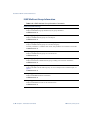
MAC Notification Status
The following command displays MAC notification status for each port/portchannel:
show mac-address-table mac-notification
Command mode: All
Port
---17
18
19
20
21
22
23
24
po1
po2
...
Mac Notification
----------------disabled
disabled
disabled
disabled
disabled
disabled
disabled
disabled
disabled
disabled
Clearing Entries From the Forwarding Database
To delete a MAC address from the forwarding database (FDB) or to clear the entire FDB, see
“Forwarding Database Maintenance” on page 205.
BMD00076, January 2009
Chapter 2: Information Commands 45
RackSwitch G8124 Command Reference
Link Aggregation Control Protocol Information
Use these commands to display LACP status information about each port on the switch.
Table 2-15 LACP Information Commands
Command Syntax and Usage
show lacp aggregator {<port alias or number>}
Displays detailed information about the LACP aggregator used by the selected port.
Command mode: All
show lacp
Displays the configured global LACP settings.
Command mode: All
show lacp information
Displays a summary of LACP information. To view an example of the command output, see
page 46.
Command mode: All
Link Aggregation Control Protocol
The following command displays LACP information:
show lacp information
Command mode: All
port
lacp
adminKey
operKey
selected
prio
attached trunk
status
aggr
-----------------------------------------------------------------------------------1
active
150
150
n
32768
--Down
2
active
150
150
n
32768
--Down
3
active
250
250
n
32768
--Down
4
active
250
250
n
32768
--Down
...
LACP dump includes the following information for each port on the switch:
lacp
Displays the port’s LACP mode (active, passive, or off)
adminkey
Displays the value of the port’s adminkey.
operkey
Shows the value of the port’s operational key.
selected
Indicates whether the port has been selected to be part of a Link Aggregation Group.
46 Chapter 2: Information Commands
BMD00076, January 2009
RackSwitch G8124 Command Reference
prio
Shows the value of the port priority.
attached aggr
Displays the aggregator associated with each port.
trunk
This value represents the LACP trunk group number.
status
This value represents the status of the port in LACP (active or down).
BMD00076, January 2009
Chapter 2: Information Commands 47
RackSwitch G8124 Command Reference
Spanning Tree Information
The following command displays Spanning Tree information:
show spanning-tree
Command mode: All
Spanning Tree Group 01: ON (RSTP)
VLANs MAPPED:
1-2,10,20
VLANs ENABLED: 1-2,10,20
Current Root:
8000 00:00:a2:87:8a:b0
Parameters:
Port Prio
---- ---1
128
Path-Cost
200000
Priority
32768
Cost
State
-------- ---200000!
FWD
Port
20
Hello
2
Hello
2
Role
Designated Bridge
---- ---------------------ROOT 8000-00:00:a2:87:8a:b0
MaxAge
20
MaxAge
20
FwdDel
15
FwdDel
15
Des Port
-------8004
Type
----P2P
! = Automatic Path Cost.
The following command displays Spanning Tree port information:
show spanning-tree stp {<1-128>}
Command mode: All
Current Spanning Tree Group 1 settings: OFF (RSTP)
Bridge params:
Priority
32768
VLANs MAPPED:
VLANs ENABLED:
1-2,10,20
1-2,10,20
STP Ports:
...
Port 17
Port 18
Port 19
Port 20
Port 21
Port 22
Port 23
Port 24
Port Channel po1
Port Channel po2
...
48 Chapter 2: Information Commands
:
:
:
:
:
:
:
:
:
:
Hello
2
Priority
Priority
Priority
Priority
Priority
Priority
Priority
Priority
Priority
Priority
MaxAge
20
128,
128,
128,
128,
128,
128,
128,
128,
128,
128,
Path
Path
Path
Path
Path
Path
Path
Path
Path
Path
FwdDel
15
Cost
Cost
Cost
Cost
Cost
Cost
Cost
Cost
Cost
Cost
0,link
0,link
0,link
0,link
0,link
0,link
0,link
0,link
0,link
0,link
Auto
Auto
Auto
Auto
Auto
Auto
Auto
Auto
Auto
Auto
BMD00076, January 2009
RackSwitch G8124 Command Reference
The switch software uses the IEEE 802.1D/2004 Rapid Spanning Tree Protocol (RSTP).
The output displays Spanning Tree status (enabled or disabled), and the following Spanning
Tree Group (STG) parameters:
Priority
Hello interval
Maximum age value
Forwarding delay
You can also view the following port-specific STG information:
STP port number
Port alias and priority
Path Cost
State
Role
Designated Bridge
Designated Port
Link Type
The following table describes the STG parameters.
Table 2-16 Spanning Tree Parameter Descriptions
Field
Description
Priority
(bridge)
The bridge priority parameter controls which bridge on the network will
become the STG root bridge.
Hello
The Hello time parameter specifies, in seconds, how often the root bridge
transmits a configuration Bridge Protocol Data Unit (BPDU). Any bridge
that is not the root bridge uses the root bridge Hello value.
MaxAge
The maximum age parameter specifies, in seconds, the maximum time the
bridge waits without receiving a configuration bridge protocol data unit
before it reconfigure the Spanning Tree network.
FwdDel
The forward delay parameter specifies, in seconds, the amount of time that a
bridge port has to wait before it changes from learning state to forwarding
state.
BMD00076, January 2009
Chapter 2: Information Commands 49
RackSwitch G8124 Command Reference
Table 2-16 Spanning Tree Parameter Descriptions
Field
Description
priority (port)
The port priority parameter helps determine which bridge port becomes the
designated port/root port. In a network topology that has multiple bridge
ports with the same path-cost connected to a single segment, the port with the
lowest port priority becomes the designated port for the segment.
Cost
The port path cost parameter is used to help determine which bridge port
becomes the designated port/root port. Generally speaking, the faster the
port, the lower the path cost. A setting of 0 indicates that the cost will be set
to the appropriate default after the link speed has been auto-negotiated.
State
The state field shows the current state of the port. The state can be Discarding (DISC), Learning (LRN, or Forwarding (FWD).
Role
The Role field shows the current role of this port in the Spanning Tree. The
port role can be one of the following: Designated (DESG), Root (ROOT),
Alternate (ALTN), Backup (BKUP), Master (MAST).
Designated
Bridge
The Designated Bridge shows information about the bridge connected to
each port, if applicable. Information includes the priority (hex) and MAC
address of the Designated Bridge.
Designated Port
The identifier of the port on the Designated Bridge to which this port is connected.
Type
Type of link connected to the port, and whether the port is an edge port. Link
type values are AUTO, P2P, or SHARED.
50 Chapter 2: Information Commands
BMD00076, January 2009
RackSwitch G8124 Command Reference
Common Internal Spanning Tree Information
The following command displays Common Internal Spanning Tree (CIST) information:
show spanning-tree mstp cist information
Command mode: All
Mstp Digest: 0xac36177f50283cd4b83821d8ab26de62
Common Internal Spanning Tree:
VLANs MAPPED: 1-4094
VLANs ENABLED: 1,4
Current Root:
8000 00:17:ef:61:87:00
Path-Cost
0
Cist Regional Root:
8000 00:17:ef:61:87:00
Path-Cost
0
Parameters:
Port
0
Priority MaxAge FwdDel
32768
20
15
20
Port Prio Cost
State
---- ---- -------- ---23
128 200000! FWD
31
128 200000! FWD
32
128 200000! FWD
45
128
20000 FWD
Role
---DESG
DESG
DESG
DESG
MaxAge
20
FwdDel
15
Hops
Designated Bridge
---------------------- 8000-00:17:ef:61:87:00
8000-00:17:ef:61:87:00
8000-00:17:ef:61:87:00
8000-00:17:ef:61:87:00
Des Port
------8017
801f
8020
802d
Hello
----2
2
2
2
Type
--P2P
P2P
P2P
P2P
! = Automatic path cost.
# = PV(R)ST Protection enabled.
The output displays the status of the CIST (enabled or disabled), and the following CIST
bridge information:
Priority
Maximum age value
Forwarding delay
You can view port-specific CIST information, including the following:
Port number and priority
Cost
Link type and Port type
BMD00076, January 2009
Chapter 2: Information Commands 51
RackSwitch G8124 Command Reference
The following table describes the CIST parameters.
Table 2-17 CIST Parameter Descriptions
Field
Description
CIST Root
The CIST Root shows information about the root bridge for the Common
Internal Spanning Tree (CIST). Values on this row of information refer to the
CIST root.
CIST Regional
Root
The CIST Regional Root shows information about the root bridge for this
MSTP region. Values on this row of information refer to the regional root.
Priority
(bridge)
The bridge priority parameter controls which bridge on the network will
become the STP root bridge.
Hello
The Hello time parameter specifies, in seconds, how often the root bridge
transmits a configuration bridge protocol data unit (BPDU). Any bridge that
is not the root bridge uses the root bridge Hello value.
MaxAge
The maximum age parameter specifies, in seconds, the maximum time the
bridge waits without receiving a configuration bridge protocol data unit
before it reconfigure the STP network.
FwdDel
The forward delay parameter specifies, in seconds, the amount of time that a
bridge port has to wait before it changes from learning state to forwarding
state.
priority (port)
The port priority parameter helps determine which bridge port becomes the
designated port/root port. In a network topology that has multiple bridge
ports with the same path-cost connected to a single segment, the port with the
lowest port priority becomes the designated port for the segment.
Cost
The port path cost parameter is used to help determine the designated port for
a segment. Generally speaking, the faster the port, the lower the path cost. A
setting of 0 indicates that the cost will be set to the appropriate default after
the link speed has been auto-negotiated.
State
The state field shows the current state of the port. The state can be Discarding (DISC), Learning (LRN, or Forwarding (FWD).
Role
The Role field shows the current role of this port in the Spanning Tree. The
port role can be one of the following: Designated (DESG), Root (ROOT),
Alternate (ALTN), Backup (BKUP), Master (MAST).
Designated
Bridge
The Designated Bridge shows information about the bridge connected to
each port, if applicable. Information includes the priority (hex) and MAC
address of the Designated Bridge.
52 Chapter 2: Information Commands
BMD00076, January 2009
RackSwitch G8124 Command Reference
Table 2-17 CIST Parameter Descriptions
Field
Description
Designated Port
The port ID of the port on the Designated Bridge to which this port is connected.
Type
Type of link connected to the port, and whether the port is an edge port.
Link type values are AUTO, P2P, or SHARED.
Trunk Group Information
Use these commands to display information about trunk groups (portchannels).
Table 2-18 Portchannel information commands
Command Syntax and Usage
show portchannel <1-12>
Displays information about the selected static trunk group.
Command mode: All
show portchannel <13-36>
Displays information about the selected LACP trunk group.
Command mode: All
show portchannel active
Displays active portchannel (trunk group) information.
Command mode: All
show portchannel information
Displays a summary of trunk group information. To view an example of the command output, see
page 54.
Command mode: All
BMD00076, January 2009
Chapter 2: Information Commands 53
RackSwitch G8124 Command Reference
Trunk Group
The following command displays Trunk Group information:
show portchannel information
Command mode: All
PortChannel group 1, Enabled
Protocol: Static
Port State:
1: Index 0 STG 1 Forwarding
2: Index 1 STG 1 Forwarding
When trunk groups are configured, you can view the state of each port in the various trunk
groups.
NOTE – If Spanning Tree Protocol on any port in the trunk group is set to Forwarding, the
remaining ports in the trunk group will also be set to Forwarding.
54 Chapter 2: Information Commands
BMD00076, January 2009
RackSwitch G8124 Command Reference
VLAN Information
The following command displays VLAN information:
show vlan
Command mode: All
VLAN
---1
4095
Name
-------------------------------VLAN 1
Mgmt VLAN
Status
-----ena
ena
Ports
------------------17-24, po1-po4
MGMT
This information display includes all configured VLANs and all member ports.
VLAN information includes:
VLAN Number
VLAN Name
Status
Port membership of the VLAN.
Trunk group (portchannel) membership of the VLAN (po1-po12 indicate static trunks
and po13-po36 indicate LACP trunks).
BMD00076, January 2009
Chapter 2: Information Commands 55
RackSwitch G8124 Command Reference
IGMP Multicast Group Information
Table 2-19 IGMP Multicast Group Information Commands
Command Syntax and Usage
show ip igmp groups address <IP address>
Displays IGMP multicast group information by the group’s IP address.
Command mode: All
show ip igmp groups interface <port alias or number>
Displays all IGMP multicast groups on a selected port.
Command mode: All
show ip igmp groups portchannel <trunk group number>
Displays all IGMP multicast groups on a selected trunk group.
Note that portchannel 1-12 indicates static trunks, and portchannel 13-36 indicate LACP trunks.
Command mode: All
show ip igmp groups vlan <1-4094>
Displays all IGMP multicast groups on a selected VLAN.
Command mode: All
show ip igmp groups detail <IP address>
Displays details about an IGMP multicast group, including source and timer information.
Command mode: All
show ip igmp groups
Displays information for all multicast groups. To view an example of the command output, see
page 57.
Command mode: All
show ip igmp mrouter information
Displays IGMP Multicast Router information.
Command mode: All
show ip igmp mrouter vlan <1-4094>
Displays IGMP multicast routers for the selected VLAN.
Command mode: All
56 Chapter 2: Information Commands
BMD00076, January 2009
RackSwitch G8124 Command Reference
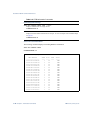
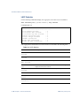
IGMP Group Information
The following command displays IGMP Group information:
show ip igmp groups
Command mode: All
Note: Local groups (224.0.0.x) are not snooped and will not appear.
Source Address
-------------10.1.1.1
10.1.1.5
*
10.10.10.43
*
Group Address
------------232.1.1.1
232.1.1.1
232.1.1.1
235.0.0.1
236.0.0.1
Vlan
---2
2
2
9
9
Port
----4
4
4
1
1
Version
------V3
V3
V3
V3
V3
Mode
------INC
INC
INC
INC
EXC
Expires
-------4:16
4:16
2:26
-
Fwd
--Yes
Yes
No
Yes
Yes
IGMP Group information includes:
IGMP source address
IGMP Group address
VLAN and port
IGMP version
IGMPv3 filter mode
Expiration timer value
IGMP multicast forwarding state
BMD00076, January 2009
Chapter 2: Information Commands 57
RackSwitch G8124 Command Reference
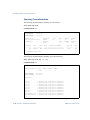
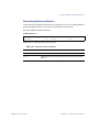
IGMP Multicast Router Information
The following command displays multicast router information:
show ip igmp mrouter information
Command mode: All
VLAN
------1
2
3
Port
------1
3
4
Version
Expires
--------- -------V3
4:09
V2
4:09
V2
static
Max Query Resp. Time
QRV
----------------------- ---128
2
125
unknown
-
QQIC
--125
-
IGMP Mrouter information includes:
VLAN and port where the Mrouter is connected
IGMP version
Mrouter expiration
Maximum query response time
Querier’s Robustness Variable (QRV)
Querier’s Query Interval Code (QQIC)
58 Chapter 2: Information Commands
BMD00076, January 2009
RackSwitch G8124 Command Reference
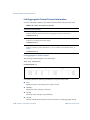
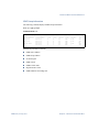
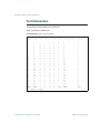
QoS Information
The following command displays 802.1p information:
show qos transmit-queue information
Command mode: All
Current priority to COS queue information:
Priority
COSq
----------0
0
1
1
2
2
3
3
4
4
5
5
6
6
7
7
Current
Port
----1
2
3
4
...
po1
po2
po3
po4
...
port priority information:
Priority
COSq
----------0
0
0
0
0
0
0
0
0
0
0
0
0
0
0
0
Table 2-20 describes the IEEE 802.1p priority-to-COS queue information.
Table 2-20 802.1p Priority-to-COS Queue parameter descriptions
Parameter
Description
Priority
Displays the 802.1p Priority level.
COSq
Displays the Class of Service queue.
BMD00076, January 2009
Chapter 2: Information Commands 59
RackSwitch G8124 Command Reference
Table 2-21 describes the IEEE 802.1p priority-to-COS queue information.
Table 2-21 802.1p Priority-to-COS Queue parameter descriptions
Field
Description
Port
Displays the port alias.
Priority
Displays the 802.1p priority level.
COSq
Displays the Class of Service queue.
QoS DSCP Information
The following command displays DSCP information:
show qos dscp
Command mode: All except User EXEC
DSCP
-------0
1
2
3
4
5
6
7
8
9
10
11
12
13
14
15
16
...
CoS Queue
--------0
0
0
0
0
0
0
0
1
1
1
1
1
1
1
1
2
Table 2-22 describes QoS DSCP information parameters.
Table 2-22 DSCP information
Field
Description
DSCP
Displays the DiffServ Code Point (DSCP) number.
CoS Queue
Displays the new Class of Service queue number.
60 Chapter 2: Information Commands
BMD00076, January 2009
RackSwitch G8124 Command Reference
Access Control List Information
The following commands display information about Access Control Lists:
Table 2-23 ACL information commands
Command Syntax and Usage
show interface port {<port alias or number>} access-list
Displays information about the ACLs assigned to the selected port.
Command mode: All
show access-list
Displays information about all configured ACLs.
Command mode: All
Access Control List Information
The following command displays Access Control List (ACL) information:
show access list
Command mode: All
BMD00076, January 2009
Chapter 2: Information Commands 61
RackSwitch G8124 Command Reference
IP ACCESS LISTS
----------------Standard IP Access List 1
---------------------------Source IP address
Source IP address mask
Destination IP address
Destination IP address mask
In Port List
Out Port List
Filter Action
User Priority
Statistics
Status
:
:
:
:
:
:
:
:
:
:
0.0.0.0
0.0.0.0
0.0.0.0
0.0.0.0
1
NULL
Deny
NIL
Disabled
Active
Extended IP Access List 1001
----------------------------Filter Protocol Type
Source IP address
Source IP address mask
Destination IP address
Destination IP address mask
In Port List
Out Port List
Filter TOS
Filter DSCP
Filter Action
User Priority
Statistics
Status
:
:
:
:
:
:
:
:
:
:
:
:
:
IP
0.0.0.0
0.0.0.0
1.1.1.1
255.255.255.255
2
NULL
NIL
NIL
Deny
NIL
Disabled
Active
:
:
:
:
:
:
:
:
:
:
10
0
00:00:00:00:00:00
00:00:00:00:00:00
3
NULL
Deny
NIL
Disabled
Active
MAC ACCESS LISTS
----------------Extended MAC Access List 1001
----------------------------Protocol Type
Vlan Id
Destination MAC Address
Source MAC Address
In Port List
Out Port List
Filter Action
User Priority
Statistics
Status
62 Chapter 2: Information Commands
BMD00076, January 2009
RackSwitch G8124 Command Reference
Access Control List (ACL) information includes configuration settings for each ACL.
Table 2-24 ACL parameter descriptions
Parameter
Description
IP Access Lists
Filter Protocol
Type
Displays the IP protocol number (or name) of the traffic to be filtered.
Filtering
FIN(SYN, ACK)
bit
Displays the TCP flag to be filtered.
Source IP
address
Displays the source IP address (host or network) of the traffic to be filtered.
Source IP
address mask
Displays the net mask address of the traffic to be filtered.
Destination IP
address
Displays the destination IP address (host or network) of the traffic
to be filtered.
Destination IP
address mask
Displays the net mask address of the traffic to be filtered.
In Port List
Displays the port(s) were the filter is applied.
Filter TOS
Displays the Type Of Service value to be filtered.
Filter DSCP
Displays the DiffServ Code Point value to be filtered.
Filter Source
Ports From
Displays the starting port number for a source port range of the TCP/UDP
traffic to be filtered.
Filter Source
Ports Till
Displays the ending port number for a source port range of the TCP/UDP
traffic to be filtered.
Filter Destination Ports From
Displays the starting port number for a destination port range of the TCP/
UDP traffic to be filtered.
Filter Destination Ports Till
Displays the ending port number for a destination port range of the TCP/
UDP traffic to be filtered.
Filter Action
Displays the filter action (permit or deny).
User Priority
Displays the value of user priority of the traffic to be filtered.
Statistics
Displays the status of the filter statistic (enable or disable).
BMD00076, January 2009
Chapter 2: Information Commands 63
RackSwitch G8124 Command Reference
Table 2-24 ACL parameter descriptions (Continued)
Parameter
Description
Status
Displays the status of the filter, as follows:
Active: The filter is assigned to a port(s).
Inactive: The filter is not assigned to a port(s).
MAC Access Lists
Protocol Type
Displays the protocol number (or name) of the traffic to be filtered.
Vlan Id
Displays the VLAN index (tag number) of the traffic to be filtered.
Destination MAC
Address
Displays the destination MAC address of the traffic to be filtered.
Source MAC
Address
Displays the source MAC address of the traffic to be filtered.
In Port List
Displays the port(s) were the filter is applied.
Filter Action
Displays the filter action (permit or deny).
User Priority
Displays the value of user priority of the traffic to be filtered.
Statistics
Displays the status of the filter statistic (enable or disable).
Status
Displays the status of the filter, as follows:
Active: The filter is assigned to a port(s).
Inactive: The filter is not assigned to a port(s).
64 Chapter 2: Information Commands
BMD00076, January 2009
RackSwitch G8124 Command Reference
RMON Information
The following commands display RMON information.
Table 2-25 RMON information commands
show rmon history <1-65535>
Displays RMON History information.
Command mode: All except User EXEC
show rmon alarms
Displays RMON Alarm information.
Command mode: All except User EXEC
show rmon events
Displays information about RMON events.
Command mode: All except User EXEC
RMON History Information
show rmon history
Command mode: All except User EXEC
Index
----1
2
IFOID
--------------ifEntry.1.20
ifEntry.1.15
Interval
-------5
1800
Rbnum
----30
30
Gbnum
----30
30
Owner
---------
Entry 1 is active : and owned by Tech1
Monitors ifEntry.1.20 every 5 second(s)
Requested # of time intervals, ie buckets, is 30,
Granted # of time intervals, ie buckets, is 30,
Sample 1 began measuring at Jan 5 06:39:46 2000
Received 0 octets, 0 packets,
0 broadcast and 0 multicast packets,
0 undersized and 0 oversized packets,
0 fragments and 0 jabbers,
0 CRC alignment errors and 0 collisions,
# of dropped packet events is 0
Network utilization is estimated at 0
BMD00076, January 2009
Chapter 2: Information Commands 65
RackSwitch G8124 Command Reference
The following table describes the RMON History information parameters.
Table 2-26 RMON History information
Field
Description
Index
Displays the index number that identifies each History instance.
IFOID
Displays the MIB Object Identifier.
Interval
Displays the time interval for each for each sampling bucket.
Rbnum
Displays the number of requested buckets, which is the number of data slots into
which data is to be saved.
Gbnum
Displays the number of granted buckets that may hold sampled data.
Owner
Displays the owner of the RMON History Group.
RMON Alarm Information
show rmon alarms
Command mode: All except User EXEC
Alarm 1 is active : owned by Tech1
Monitors 1.3.6.1.2.1.5.1.0 every 1800 second(s)
Taking absolute samples, last value was 0
Rising threshold is 50, assigned to event 1
Falling threshold is 25, assigned to event 1
On startup enable rising or falling alarm
Alarm Logs Generated:
Logging Event With Description : , logged 2 times for Event 1
Alarm 2 is active : owned by Tech1
Monitors 1.3.6.1.2.1.5.2.0 every 1800 second(s)
Taking absolute samples, last value was 0
Rising threshold is 50, assigned to event 1
On startup enable rising alarm
66 Chapter 2: Information Commands
BMD00076, January 2009
RackSwitch G8124 Command Reference
RMON Event Information
show rmon events
Command mode: All except User EXEC
Event 1 is active : owned by Tech1
Description is Syslog/trap IcmpInEchoes
Event firing causes log and trap to community public,
Time last sent is Jan 5 06:45:43 2009
Logging Event With Description : , logged 2 times for Event 1
Event 2 is active : owned by Tech1
Description is Trap ifInOctets
Event firing causes trap to community public,
Time last sent is Jan 5 06:24:45 2009
BMD00076, January 2009
Chapter 2: Information Commands 67
RackSwitch G8124 Command Reference
Port Information
The following command displays port information:
show interface information
Command mode: All except User EXEC
Alias
-----
Port
----
Tag
---
Edge
----
1
1
n
n
2
2
n
n
3
3
n
n
4
4
n
n
5
5
n
n
6
6
n
n
7
7
n
n
8
8
n
n
9
9
n
n
10
10
n
n
11
11
n
n
12
12
n
n
13
13
n
n
14
14
n
n
15
15
n
n
16
16
n
n
17
17
n
n
18
18
n
n
19
19
n
n
20
20
n
n
21
21
n
n
22
22
n
n
23
23
n
n
24
24
n
n
MGMT
MGMT
n
n
# = PVID is tagged.
68 Chapter 2: Information Commands
Lrn
---
Fld
---
PVID
----
NAME
-------------
VLAN(s)
-------
e
e
e
e
e
e
e
e
e
e
e
e
e
e
e
e
e
e
e
e
e
e
e
e
d
e
e
e
e
e
e
e
e
e
e
e
e
e
e
e
e
e
e
e
e
e
e
e
e
d
1
1
1
1
1
1
1
1
1
1
1
1
1
1
1
1
1
1
1
1
1
1
1
1
4095
1
2
3
4
5
6
7
8
9
10
11
12
13
14
15
16
17
18
19
20
21
22
23
24
MGMT
1
1
1
1
1
1
1
1
1
1
1
1
1
1
1
1
1
1
1
1
1
1
1
1
4095
BMD00076, January 2009
RackSwitch G8124 Command Reference
Port information includes:
Port alias and number
Whether the port uses VLAN tagging or not (y or n)
Whether the port is configured for Port Fast Fowarding (Fast)
Whether the port is enabled for FDB Learning (Lrn)
Whether the port is enabled for flooding of unknown destination MACs (Fld)
Port VLAN ID (PVID)
Port name
VLAN membership
BMD00076, January 2009
Chapter 2: Information Commands 69
RackSwitch G8124 Command Reference
Interface Link Information
The following command displays port link status for each port on the switch:
show interface link
Command mode: All except User EXEC
Alias
----1
2
3
4
5
6
7
8
9
10
11
12
13
14
15
16
17
18
19
20
21
22
23
24
Port
---1
2
3
4
5
6
7
8
9
10
11
12
13
14
15
16
17
18
19
20
21
22
23
24
Speed
Duplex
-----------10000*
full*
10000*
full*
10000*
full*
10000*
full*
10000*
full*
10000*
full*
10000*
full*
10000*
full*
10000*
full*
10000*
full*
10000*
full*
10000*
full*
10000*
full*
10000*
full*
10000*
full*
10000*
full*
10000*
full*
10000*
full*
10000*
full*
10000*
full*
10000*
full*
10000*
full*
10000*
full*
10000*
full*
Flow Ctrl
--TX-----RX-yes*
yes*
yes*
yes*
yes*
yes*
yes*
yes*
yes*
yes*
yes*
yes*
yes*
yes*
yes*
yes*
yes*
yes*
yes*
yes*
yes*
yes*
yes*
yes*
yes*
yes*
yes*
yes*
yes*
yes*
yes*
yes*
yes*
yes*
yes*
yes*
yes*
yes*
yes*
yes*
yes*
yes*
yes*
yes*
yes*
yes*
yes*
yes*
Link
-----up
up
up
up
up
up
up
up
up
down
up
up
up
up
up
up
up
up
up
up
up
up
up
up
Name
-----1
2
3
4
5
6
7
8
9
11
12
13
14
15
16
17
18
19
20
21
22
23
24
Port link information includes the following:
Port alias and number
Port speed (10, 100, 1000, or any)
Duplex mode (half, full, or any)
Flow control for transmit and receive (no or yes)
Link status (up, down, or disabled)
70 Chapter 2: Information Commands
BMD00076, January 2009
RackSwitch G8124 Command Reference
Interface Transceivers
The following command displays transceivers used on the switch.
show interface transceivers
Command mode: All except User EXEC
Ports :
SFP1 SFP+: Is Present NOT APPROVED
SFP2 SFP+: Is Present Is Approved
Vendor:Blade Network
Part:BN-CKM-SP-SR
Rev:-SPLaser:850nm Serial:AD0752E01KL
Date:071225
SFP3 SFP+: Is Present NOT APPROVED
SFP4 SFP+: Is Present NOT APPROVED
Information Dump
The following command dumps switch information:
show information-dump
Command mode: All
Use the dump command to dump all switch information available (10K or more, depending on
your configuration). This data is useful for tuning and debugging switch performance.
If you want to capture dump data to a file, set your communication software on your workstation to capture session data prior to issuing the dump commands.
BMD00076, January 2009
Chapter 2: Information Commands 71
RackSwitch G8124 Command Reference
72 Chapter 2: Information Commands
BMD00076, January 2009
CHAPTER 3
Statistics Commands
You can view switch performance statistics in the user, operator, and administrator command
modes. This chapter discusses how to use the ISCLI to display switch statistics.
Table 3-1 Statistics Commands
Command Syntax and Usage
show snmp-server
Displays the current SNMP configuration parameters. To view an example of the command output,
see page 98.
Command mode: All
show snmp-server counters
Displays SNMP statistics. To view an example of the command output, see page 98.
Command mode: All
clear ntp
Clears Network Time Protocol (NTP) statistics.
Command mode: All except User EXEC
clear ntp primary-server
Clears statistics for the primary NTP server.
Command mode: All except User EXEC
clear ntp secondary-server
Clears statistics for the secondary NTP server.
Command mode: All except User EXEC
show counters
Dumps all switch statistics. Use this command to gather data for tuning and debugging switch performance. If you want to capture dump data to a file, set your communication software on your
workstation to capture session data prior to issuing the dump command. To view an example of the
command output, see page 103.
Command mode: All
BMD00076, January 2009
73
RackSwitch G8124 Command Reference
Port Statistics
These commands display traffic statistics on a port-by-port basis. Traffic statistics include
SNMP Management Information Base (MIB) objects.
Table 3-2 Port Statistics Commands
Command Syntax and Usage
show interface port {<port alias or number, or range of ports>} bridging-counters
Displays bridging (“dot1”) statistics for the port. To view an example of the command output, see
page 76.
Command mode: All
show interface port {<port alias or number, or range of ports>} ethernet-counters
Displays Ethernet (“dot3”) statistics for the port. To view an example of the command output, see
page 77.
Command mode: All
show interface port {<port alias or number, or range of ports>} interface-counters
Displays interface statistics for the port. To view an example of the command output, see page 80.
Command mode: All
show interface port {<port alias or number, or range of ports>} ip-counters
Displays IP statistics for the port.
Command mode: All
show interface port {<port alias or number, or range of ports>} lacp counters
Displays Link Aggregation Control Protocol (LACP) statistics for the port. To view an example of
the command output, see page 82.
Command mode: All
show interface port {<port alias or number, or range of ports>} link-counters
Displays link statistics for the port. To view an example of the command output, see page 83.
Command mode: All
clear interface port {<port alias or number>} counters
Clears all statistics for the port.
Command mode: All except User EXEC
clear interfaces
Clears statistics for all ports.
Command mode: All except User EXEC
74 Chapter 3: Statistics Commands
BMD00076, January 2009
RackSwitch G8124 Command Reference
Table 3-2 Port Statistics Commands
Command Syntax and Usage
show interface port {<port alias or number, or range of ports>} link-counters
Displays link statistics for the port. To view an example of the command output, see page 83.
Command mode: All
clear interface port {<port alias or number, or range of ports>} counters
Clears all statistics counters for the selected ports.
Command mode: Global configuration
clear interfaces counters
Clears statistics counters for all ports.
Command mode: All except User EXEC
BMD00076, January 2009
Chapter 3: Statistics Commands 75
RackSwitch G8124 Command Reference
Bridging Statistics
Use the following command to display the bridging statistics of the selected port:
show interface port {<port alias or number>} bridging-counters
Command mode: All
Bridging statistics for port 1:
dot1PortInFrames:
dot1PortOutFrames:
dot1PortInDiscards:
dot1StpPortForwardTransitions:
63242584
63277826
296
1
Table 3-3 Port Bridging Statistics
Statistics
Description
dot1PortInFrames
The number of frames that have been received by this port from its segment. A frame received on the interface corresponding to this port is only
counted by this object if and only if it is for a protocol being processed by
the local bridging function, including bridge management frames.
dot1PortOutFrames
The number of frames that have been transmitted by this port to its segment. Note that a frame transmitted on the interface corresponding to this
port is only counted by this object if and only if it is for a protocol being
processed by the local bridging function, including bridge management
frames.
dot1PortInDiscards
Count of valid frames received which were discarded (that is, filtered) by
the Forwarding Process.
dot1StpPortForward
Transitions
The number of times this port has transitioned from the Learning state to
the Forwarding state.
76 Chapter 3: Statistics Commands
BMD00076, January 2009
RackSwitch G8124 Command Reference
Ethernet Statistics
Use the following command to display the ethernet statistics of the selected port:
show interface port {<port alias or number>} ethernet-counters
Command mode: All
Ethernet statistics for port 1
dot3StatsAlignmentErrors:
dot3StatsFCSErrors:
dot3StatsSingleCollisionFrames:
dot3StatsMultipleCollisionFrames:
dot3StatsLateCollisions:
dot3StatsExcessiveCollisions:
dot3StatsInternalMacTransmitErrors:
dot3StatsFrameTooLongs:
dot3StatsInternalMacReceiveErrors:
1070721424
1070721424
0**
0**
0**
0**
0**
1070721424
1070721424
Table 3-4 Ethernet Statistics for Port
Statistics
Description
dot3StatsAlignment
Errors
A count of frames received on a particular interface that are not an integral number of octets in length and do not pass the Frame Check
Sequence (FCS) check.
The count represented by an instance of this object is incremented when
the alignmentError status is returned by the MAC service to the
Logical Link Control (LLC) (or other MAC user). Received frames for
which multiple error conditions obtained are, according to the conventions of IEEE 802.3 Layer Management, counted exclusively according
to the error status presented to the LLC.
dot3StatsFCSErrors
A count of frames received on a particular interface that are an integral
number of octets in length but do not pass the Frame Check Sequence
(FCS) check.
The count represented by an instance of this object is incremented when
the frameCheckError status is returned by the MAC service to the
LLC (or other MAC user). Received frames for which multiple error conditions obtained are, according to the conventions of IEEE 802.3 Layer
Management, counted exclusively according to the error status presented
to the LLC.
BMD00076, January 2009
Chapter 3: Statistics Commands 77
RackSwitch G8124 Command Reference
Table 3-4 Ethernet Statistics for Port
Statistics
Description
dot3StatsSingleCollisionFrames
A count of successfully transmitted frames on a particular interface for
which transmission is inhibited by exactly one collision.
A frame that is counted by an instance of this object is also counted by the
corresponding instance of either the ifOutUcastPkts, ifOutMulticastPkts, or ifOutBroadcastPkts, and is not counted by the
corresponding instance of the dot3StatsMultipleCollisionFrame object.
dot3StatsMultipleCollisionFrames
A count of successfully transmitted frames on a particular interface for
which transmission is inhibited by more than one collision.
A frame that is counted by an instance of this object is also counted by the
corresponding instance of either the ifOutUcastPkts, ifOutMulticastPkts, or ifOutBroadcastPkts, and is not counted by the
corresponding instance of the dot3StatsSingleCollisionFrames object.
dot3StatsLateCollisions
The number of times that a collision is detected on a particular interface
later than 512 bit-times into the transmission of a packet.
Five hundred and twelve bit-times corresponds to 51.2 microseconds on a
10 Mbit/s system. A (late) collision included in a count represented by an
instance of this object is also considered as a (generic) collision for purposes of other collision-related statistics.
dot3StatsExcessive
Collisions
A count of frames for which transmission on a particular interface fails
due to excessive collisions.
dot3StatsInternalMacTransmitErrors
A count of frames for which transmission on a particular interface fails
due to an internal MAC sub layer transmit error. A frame is only counted
by an instance of this object if it is not counted by the corresponding
instance of either the dot3StatsLateCollisions object, the
dot3StatsExcessiveCollisions object, or the dot3StatsCarrierSenseErrors object.
The precise meaning of the count represented by an instance of this object
is implementation-specific. In particular, an instance of this object may
represent a count of transmission errors on a particular interface that are
not otherwise counted.
78 Chapter 3: Statistics Commands
BMD00076, January 2009
RackSwitch G8124 Command Reference
Table 3-4 Ethernet Statistics for Port
Statistics
Description
dot3StatsFrameTooLongs
A count of frames received on a particular interface that exceed the maximum permitted frame size.
The count represented by an instance of this object is incremented when
the frameTooLong status is returned by the MAC service to the LLC
(or other MAC user). Received frames for which multiple error conditions obtained are, according to the conventions of IEEE 802.3 Layer
Management, counted exclusively according to the error status presented
to the LLC.
dot3StatsInternalMacReceiveErrors
A count of frames for which reception on a particular interface fails due
to an internal MAC sub layer receive error. A frame is only counted by an
instance of this object if it is not counted by the corresponding instance of
either the dot3StatsFrameTooLongs object, the dot3StatsAlignmentErrors object, or the dot3StatsFCSErrors object.
The precise meaning of the count represented by an instance of this object
is implementation-specific. In particular, an instance of this object may
represent a count of received errors on a particular interface that are not
otherwise counted.
BMD00076, January 2009
Chapter 3: Statistics Commands 79
RackSwitch G8124 Command Reference
Interface Statistics
Use the following command to display the interface statistics of the selected port:
show interface port {<port alias or number>} interface-counters
Command mode: All
Interface statistics for port 1
ifHCIn Counters
Octets:
0
UcastPkts:
0
BroadcastPkts:
0
MulticastPkts:
0
Discards:
0
Errors:
0
ifHCOut Counters
929591360
1169045
3934187
2425859
855
0
Table 3-5 Interface Statistics for Port
Statistics
Description
ifHCIn Counters
Octets
The total number of octets received on the interface, including framing
characters.
ifHCIn Counters
UcastPkts
The number of packets, delivered by this sub-layer to a higher sub- layer,
which were not addressed to a multicast or broadcast address at this sublayer.
ifHCIn Counters
BroadcastPkts
The number of packets, delivered by this sub-layer to a higher sub- layer,
which were addressed to a broadcast address at this sub-layer.
ifHCIn Counters
MulticastPkts
The total number of packets that higher-level protocols requested to be
transmitted, and which were addressed to a multicast address at this sublayer, including those that were discarded or not sent. For a MAC layer
protocol, this includes both Group and Functional addresses.
ifHCIn Counters
Discards
The number of inbound packets which were chosen to be discarded even
though no errors had been detected to prevent their being delivered to a
higher-layer protocol. One possible reason for discarding such a packet
could be to free up buffer space.
ifHCIn Counters
Errors
For packet-oriented interfaces, the number of inbound packets that contained errors preventing them from being delivered to a higher-layer protocol. For character-oriented or fixed-length interfaces, the number of
inbound transmission units that contained errors preventing them from
being deliverable to a higher-layer protocol.
ifHCOut Counters
Octets
The total number of octets transmitted out of the interface, including
framing characters.
80 Chapter 3: Statistics Commands
BMD00076, January 2009
RackSwitch G8124 Command Reference
Table 3-5 Interface Statistics for Port
Statistics
Description
ifHCOut Counters
UcastPkts
The total number of packets that higher-level protocols requested to be
transmitted, and which were not addressed to a multicast or broadcast
address at this sub-layer, including those that were discarded or not sent.
ifHCOut Counters
BroadcastPkts
The total number of packets that higher-level protocols requested to be
transmitted, and which were addressed to a broadcast address at this sublayer, including those that were discarded or not sent. This object is a 64bit version of ifOutBroadcastPkts.
ifHCOut Counters
MulticastPkts
The total number of packets that higher-level protocols requested to be
transmitted, and which were addressed to a multicast address at this sublayer, including those that were discarded or not sent. For a MAC layer
protocol, this includes both Group and Functional addresses. This object
is a 64-bit version of ifOutMulticastPkts.
ifHCOut Counters
Discards
The number of outbound packets which were chosen to be discarded even
though no errors had been detected to prevent their being transmitted.
One possible reason for discarding such a packet could be to free up
buffer space.
ifHCOut Counters
Errors
For packet-oriented interfaces, the number of outbound packets that
could not be transmitted because of errors. For character-oriented or
fixed-length interfaces, the number of outbound transmission units that
could not be transmitted because of errors.
BMD00076, January 2009
Chapter 3: Statistics Commands 81
RackSwitch G8124 Command Reference
LACP Statistics
Use the following command to display Link Aggregation Control Protocol (LACP) statistics:
show interface port {<port alias or number>} lacp counters
Command mode: All
port 1
----------------------------------------Valid LACPDUs received:
- 0
Valid Marker PDus received:
- 0
Valid Marker Rsp PDus received: - 0
Unknown version/TLV type:
- 0
Illegal subtype received:
- 0
LACPDUs transmitted:
- 0
Marker PDUs transmitted:
- 0
Marker Rsp PDUs transmitted:
- 0
Link Aggregation Control Protocol (LACP) statistics are described in the following table:
Table 3-6 LACP Statistics
Statistic
Description
Valid LACPDUs
received
Total number of valid LACP data units received.
Valid Marker PDUs
received
Total number of valid LACP marker data units received.
Valid Marker Rsp
PDUs received
Total number of valid LACP marker response data units received.
Unknown version/TLV Total number of LACP data units with an unknown version or type,
type
length, and value (TLV) received.
Illegal subtype
received
Total number of LACP data units with an illegal subtype received.
LACPDUs transmitted Total number of LACP data units transmitted.
Marker PDUs transmitted
Total number of LACP marker data units transmitted.
Marker Rsp PDUs
transmitted
Total number of LACP marker response data units transmitted.
82 Chapter 3: Statistics Commands
BMD00076, January 2009
RackSwitch G8124 Command Reference
Link Statistics
Use the following command to display the link statistics of the selected port:
show interface port {<port alias or number>} link-counters
Command mode: All
Link statistics for port:1
linkStateChange:1
Table 3-7 Link Statistics
Statistics
Description
linkStateChange
The total number of link state changes.
BMD00076, January 2009
Chapter 3: Statistics Commands 83
RackSwitch G8124 Command Reference
Layer 2 Statistics
This section explains the Layer 2 statistics commands.
Table 3-8 Layer 2 Statistics Commands
Command Syntax and Usage
show mac-address-table counters
Displays Forwarding Database (FDB) statistics. To view an example of the command output, see
page 85.
Command mode: All
clear mac-address-table counters
Clears FDB statistics.
Command mode: All except User EXEC
show ufd counters
Displays Uplink Failure Detection statistics.
Command mode: All
clear ufd-counters
Clears Uplink Failure Detection statistics.
Command mode: All except User EXEC
clear interfaces counters
Clears all statistics of all interfaces.
Command mode: All except User EXEC
show interface port {<port alias or number>} lacp counters
Displays Link Aggregation Control Protocol (LACP) statistics. To view an example of the command output, see page 82.
Command mode: All
84 Chapter 3: Statistics Commands
BMD00076, January 2009
RackSwitch G8124 Command Reference
Forwarding Database Statistics
Use the following command to display statistics regarding the use of the Forwarding Database
(FDB), including the number of new entries, finds, and unsuccessful searches:
show mac-address-table counters
Command mode: All
FDB statistics:
current:
85
hiwat:
129
FDB statistics are described in the following table:
Table 3-9 Forwarding Database Statistics
Statistic
Description
current
Current number of entries in the Forwarding Database.
hiwat
Highest number of entries recorded at any given time in the Forwarding
Database.
BMD00076, January 2009
Chapter 3: Statistics Commands 85
RackSwitch G8124 Command Reference
Layer 3 Statistics
The following table describes the commands that you can enter to view Layer 3 statistics.
Table 3-10 Layer 3 Statistics Commands
Command Syntax and Usage
show ip dns
Displays the current Domain Name System settings.
Command mode: Global configuration
show ip igmp counters
Displays IGMP statistics. To view an example of the command output, see page 87.
Command mode: All
clear ip igmp [<VLAN number>]counters
Clears IGMP Snooping statistics counters. Enter the VLAN number to clear statistics on the
selected VLAN.
Command mode: All except User EXEC
show ip icmp counters
Displays Internet Control Message Protocol (ICMP) statistics. To view an example of the command output, see page 88.
Command mode: All
show ip tcp counters
Displays Transmission Control Protocol (TCP) statistics. To view an example of the command output, see page 90.
Command mode: All
show ip udp counters
Displays User Datagram Protocol (UDP) statistics. To view an example of the command output,
see page 91.
Command mode: All
show layer3 counters
Dumps all Layer 3 statistics. Use this command to gather data for tuning and debugging switch
performance. If you want to capture dump data to a file, set your communication software on your
workstation to capture session data prior to issuing the dump command.
Command mode: All
86 Chapter 3: Statistics Commands
BMD00076, January 2009
RackSwitch G8124 Command Reference
IGMP Statistics
The following command displays statistics about the use of the IGMP Multicast Groups:
show ip igmp counters
Command mode: All
IGMP Snoop vlan 2 statistics:
----------------------------------------------------------------------rxIgmpValidPkts:
0
rxIgmpInvalidPkts:
0
rxIgmpGenQueries:
0
rxIgmpGrpSpecificQueries:
0
rxIgmpGroupSrcSpecificQueries: 0
rxIgmpLeaves:
0
rxIgmpReports:
0
txIgmpReports:
0
txIgmpGrpSpecificQueries:
0
txIgmpLeaves:
0
rxIgmpV3CurrentStateRecords:
0
rxIgmpV3SourceListChangeRecords:0
rxIgmpV3FilterChangeRecords:
0
Table 3-11 IGMP Statistics
Statistic
Description
rxIgmpValidPkts
Total number of valid IGMP packets received.
rxIgmpInvalidPkts
Total number of invalid packets received.
rxIgmpGenQueries
Total number of General Membership Query
packets received.
rxIgmpGrpSpecificQueries
Total number of Group Specific Queries
received.
rxIgmpGroupSrcSpecificQueries
Total number of Group Source-Specific Queries
(GSSQ) received.
rxIgmpLeaves
Total number of Leave requests received.
rxIgmpReports
Total number of Membership Reports received.
txIgmpReports
Total number of Membership reports transmitted.
txIgmpGrpSpecificQueries
Total number of Membership Query packets
transmitted to specific groups.
txIgmpLeaves
Total number of Leave messages transmitted.
rxIgmpV3CurrentStateRecords
Total number of Current State records received.
rxIgmpV3SourceListChangeRecords
Total number of Source List Change records
received.
rxIgmpV3FilterChangeRecords
Total number of Filter Change records received.
BMD00076, January 2009
Chapter 3: Statistics Commands 87
RackSwitch G8124 Command Reference
ICMP Statistics
The following command displays ICMP statistics:
show ip icmp counters
Command mode: All
ICMP statistics:
icmpInMsgs:
icmpInDestUnreachs:
icmpInParmProbs:
icmpInRedirects:
icmpInEchoReps:
icmpInTimestampReps:
icmpInAddrMaskReps:
icmpOutErrors:
icmpOutTimeExcds:
icmpOutSrcQuenchs:
icmpOutEchos:
icmpOutTimestamps:
icmpOutAddrMasks:
245802
41
0
0
244350
0
0
0
0
0
253777
0
0
icmpInErrors:
icmpInTimeExcds:
icmpInSrcQuenchs:
icmpInEchos:
icmpInTimestamps:
icmpInAddrMasks:
icmpOutMsgs:
icmpOutDestUnreachs:
icmpOutParmProbs:
icmpOutRedirects:
icmpOutEchoReps:
icmpOutTimestampReps:
icmpOutAddrMaskReps:
1393
0
0
18
0
0
253810
15
0
0
18
0
0
Table 3-12 ICMP Statistics
Statistics
Description
icmpInMsgs
The total number of ICMP messages which the entity (the switch)
received. Note that this counter includes all those counted by
icmpInErrors.
icmpInErrors
The number of ICMP messages which the entity (the switch)
received but determined as having ICMP-specific errors (bad ICMP
checksums, bad length, and so forth).
icmpInDestUnreachs
The number of ICMP Destination Unreachable messages received.
icmpInTimeExcds
The number of ICMP Time Exceeded messages received.
icmpInParmProbs
The number of ICMP Parameter Problem messages received.
icmpInSrcQuenchs
The number of ICMP Source Quench (buffer almost full, stop sending data) messages received.
icmpInRedirects
The number of ICMP Redirect messages received.
icmpInEchos
The number of ICMP Echo (request) messages received.
icmpInEchoReps
The number of ICMP Echo Reply messages received.
icmpInTimestamps
The number of ICMP Timestamp (request) messages received.
88 Chapter 3: Statistics Commands
BMD00076, January 2009
RackSwitch G8124 Command Reference
Table 3-12 ICMP Statistics
Statistics
Description
icmpInTimestampReps
The number of ICMP Timestamp Reply messages received.
icmpInAddrMasks
The number of ICMP Address Mask Request messages received.
icmpInAddrMaskReps
The number of ICMP Address Mask Reply messages received.
icmpOutMsgs
The total number of ICMP messages which this entity (the switch)
attempted to send. Note that this counter includes all those counted
by icmpOutErrors.
icmpOutErrors
The number of ICMP messages which this entity (the switch) did not
send due to problems discovered within ICMP such as a lack of
buffer. This value should not include errors discovered outside the
ICMP layer such as the inability of IP to route the resultant datagram. In some implementations there may be no types of errors that
contribute to this counter's value.
icmpOutDestUnreachs
The number of ICMP Destination Unreachable messages sent.
icmpOutTimeExcds
The number of ICMP Time Exceeded messages sent.
icmpOutParmProbs
The number of ICMP Parameter Problem messages sent.
icmpOutSrcQuenchs
The number of ICMP Source Quench (buffer almost full, stop sending data) messages sent.
icmpOutRedirects
The number of ICMP Redirect messages sent. For a host, this object
will always be zero, since hosts do not send redirects.
icmpOutEchos
The number of ICMP Echo (request) messages sent.
icmpOutEchoReps
The number of ICMP Echo Reply messages sent.
icmpOutTimestamps
The number of ICMP Timestamp (request) messages sent.
icmpOutTimestampReps
The number of ICMP Timestamp Reply messages sent.
icmpOutAddrMasks
The number of ICMP Address Mask Request messages sent.
icmpOutAddrMaskReps
The number of ICMP Address Mask Reply messages sent.
BMD00076, January 2009
Chapter 3: Statistics Commands 89
RackSwitch G8124 Command Reference
TCP Statistics
The following command displays TCP statistics:
show ip tcp counters
Command mode: All
TCP statistics:
tcpRtoAlgorithm:
tcpRtoMax:
tcpActiveOpens:
tcpAttemptFails:
tcpInSegs:
tcpRetransSegs:
tcpCurBuff:
tcpOutRsts:
4
240000
252214
528
756401
0
0
417
tcpRtoMin:
tcpMaxConn:
tcpPassiveOpens:
tcpEstabResets:
tcpOutSegs:
tcpInErrs:
tcpCurConn:
0
512
7
4
756655
0
3
Table 3-13 TCP Statistics
Statistics
Description
tcpRtoAlgorithm
The algorithm used to determine the timeout value used for retransmitting unacknowledged octets.
tcpRtoMin
The minimum value permitted by a TCP implementation for the retransmission timeout, measured in milliseconds. More refined semantics
for objects of this type depend upon the algorithm used to determine the
retransmission timeout. In particular, when the timeout algorithm is
rsre(3), an object of this type has the semantics of the LBOUND quantity
described in RFC 793.
tcpRtoMax
The maximum value permitted by a TCP implementation for the retransmission timeout, measured in milliseconds. More refined semantics
for objects of this type depend upon the algorithm used to determine the
retransmission timeout. In particular, when the timeout algorithm is
rsre(3), an object of this type has the semantics of the UBOUND quantity
described in RFC 793.
tcpMaxConn
The limit on the total number of TCP connections the entity (the switch)
can support. In entities where the maximum number of connections is
dynamic, this object should contain the value -1.
tcpActiveOpens
The number of times TCP connections have made a direct transition to
the SYN-SENT state from the CLOSED state.
tcpPassiveOpens
The number of times TCP connections have made a direct transition to
the SYN-RCVD state from the LISTEN state.
90 Chapter 3: Statistics Commands
BMD00076, January 2009
RackSwitch G8124 Command Reference
Table 3-13 TCP Statistics
Statistics
Description
tcpAttemptFails
The number of times TCP connections have made a direct transition to
the CLOSED state from either the SYN-SENT state or the SYN-RCVD
state, plus the number of times TCP connections have made a direct transition to the LISTEN state from the SYN-RCVD state.
tcpEstabResets
The number of times TCP connections have made a direct transition to
the CLOSED state from either the ESTABLISHED state or the CLOSEWAIT state.
tcpInSegs
The total number of segments received, including those received in error.
This count includes segments received on currently established connections.
tcpOutSegs
The total number of segments sent, including those on current connections but excluding those containing only retransmitted octets.
tcpRetransSegs
The total number of segments retransmitted - that is, the number of TCP
segments transmitted containing one or more previously transmitted octets.
tcpInErrs
The total number of segments received in error (for example, bad TCP
checksums).
tcpCurBuff
The total number of outstanding memory allocations from heap by TCP
protocol stack.
tcpCurConn
The total number of outstanding TCP sessions that are currently opened.
tcpOutRsts
The number of TCP segments sent containing the RST flag.
UDP Statistics
The following command displays UDP statistics:
show ip udp counters
Command mode: All
UDP statistics:
udpInDatagrams:
udpInErrors:
BMD00076, January 2009
54
0
udpOutDatagrams:
udpNoPorts:
43
1578077
Chapter 3: Statistics Commands 91
RackSwitch G8124 Command Reference
Table 3-14 UDP Statistics
Statistics
Description
udpInDatagrams
The total number of UDP datagrams delivered to the switch.
udpOutDatagrams
The total number of UDP datagrams sent from this entity (the switch).
udpInErrors
The number of received UDP datagrams that could not be delivered for
reasons other than the lack of an application at the destination port.
udpNoPorts
The total number of received UDP datagrams for which there was no
application at the destination port.
92 Chapter 3: Statistics Commands
BMD00076, January 2009
RackSwitch G8124 Command Reference
ACL Statistics
The following table describes the commands to display Access Control List (ACL) statistics:
Table 3-15 ACL Statistics Commands
Command Syntax and Usage
show access-list ip counters
Displays IP ACL statistics.
Command mode: All
show access-list mac counters
Displays MAC ACL statistics.
Command mode: All
show access-list <ACL number> counters
Displays statistics for the selected ACL.
Command mode: All
show access-list counters
Displays all ACL statistics.
Command mode: All
The following command displays Access Control List (ACL) statistics:
show access-list counters
Command mode: All
IP ACCESS LISTS
----------------Hits for ACL 1
10000
MAC ACCESS LISTS
----------------ACL stats are disabled
BMD00076, January 2009
Chapter 3: Statistics Commands 93
RackSwitch G8124 Command Reference
Management Processor Statistics
The following table describes the commands used to display statistics about the switch’s management processor.
Table 3-16 Management Processor Statistics commands
Command Syntax and Usage
show mp packet
Displays packet statistics, to check for leads and load.
Command mode: All
To view a sample output, see page 94.
show mp tcp-block
Displays all Transmission Control Protocol (TCP) control blocks (TCB) that are in use.
Command mode: All
To view a sample output, see page 95.
show mp udp-block
Displays all User Datagram Protocol (UDP) control blocks (UCB) that are in use.
Command mode: All
To view a sample output, see page 96.
show mp cpu
Displays CPU utilization for periods of up to 1, 5, and 15 minutes.
Command mode: All
To view a sample output, see page 97.
Packet Statistics
The following command displays packet statistics:
show mp packet
Command mode: All
Packet counts:
allocs:
hi-watermark:
94 Chapter 3: Statistics Commands
1233687 frees:
89 failures:
1233683
0
BMD00076, January 2009
RackSwitch G8124 Command Reference
Table 3-17 describes the packet statistics shown in this example:
Table 3-17 Packet Statistics
Statistic
Description
allocs
Total number of packet allocations from the packet buffer pool by the
TCP/IP protocol stack.
frees
Total number of times the packet buffers are freed (released) to the
packet buffer pool by the TCP/IP protocol stack.
hi-watermark
The highest number of packet allocation from the packet buffer pool
by the TCP/IP protocol stack.
failures
Total number of packet allocation failures from the packet buffer pool
by the TCP/IP protocol stack.
TCP Statistics
The following command displays TCP statistics:
show mp tcp-block
Command mode: All
TCP ALLOCATED CONTROL BLOCKS
12.16.20.10
443 <=>
10.10.10.112
12.31.80.206
23 <=>
10.10.10.127
3804
2531
LISTEN
ESTABLISHED
Table 3-18 describes the Transmission Control Protocol (TCP) control block (TCB) statistics
shown in this example:
Table 3-18 TCP Statistics
Description
Example
Destination IP address
12.16.20.10
Destination port
443
Source IP address
10.10.10.112
Source port
3804
State
Listen
BMD00076, January 2009
Chapter 3: Statistics Commands 95
RackSwitch G8124 Command Reference
UDP Statistics
The following command displays UDP statistics:
show mp udp-block
Command mode: All
UDP ALLOCATED
10.10.10.12
0.0.0.0
0.0.0.0
0.0.0.0
0.0.0.0
0.0.0.0
0.0.0.0
0.0.0.0
CONTROL
68
123
161
1812
1813
6123
7000
9000
BLOCKS
LISTEN
LISTEN
LISTEN
LISTEN
LISTEN
LISTEN
LISTEN
LISTEN
Table 3-19 describes the User Datagram Protocol (UDP) control block statistics shown in this
example:
Table 3-19 UDP Statistics
Description
Example
IP address
10.10.10.12
Control block
68
State
Listen
96 Chapter 3: Statistics Commands
BMD00076, January 2009
RackSwitch G8124 Command Reference
CPU Statistics
The following command displays the CPU utilization statistics:
show mp cpu
Command mode: All except User EXEC.
CPU information:
Load Average (over the last 1 min):
0.45
Load Average (over the last 5 mins):
0.34
Load Average (over the last 15 mins):
0.28
Runnable tasks/Total processes:
1/57
PID of the most recent process:
274
----------------------------------------------------------Memory information:
total:
used:
free:
shared: buffers: cached:
Mem: 203755520 143568896 60186624 34054144 62914560 24567808
...
CPU utilization statistics to note are listed below:
The percentage of MP CPU utilization over 1 minute, 5 minutes, and 15 minutes.
Total memory available
Total memory used
BMD00076, January 2009
Chapter 3: Statistics Commands 97
RackSwitch G8124 Command Reference
SNMP Statistics
The following command displays current SNMP parameters:
show snmp-server
Command mode: All
Current SNMP params
sysName:
sysLocation:
sysContact:
Read community string:
Write community string:
Trap source address:
Authentication traps
All link up/down traps
"RS G8124"
"g8124"
"Blade Network Technologies"
"public"
"private"
12.31.80.206
disabled.
enabled.
Current v1/v2 access enabled
The following command displays SNMP statistics:
show snmp-server counters
Command mode: All
SNMP statistics:
----------------------------------------------------------------snmpInPkts:
1351
snmpInBadVersions:
0
snmpInBadC'tyNames:
12
snmpInBadC'tyUses:
679
snmpInASNParseErrs:
660
snmpEnableAuthTraps:
2
snmpOutPkts:
1339
snmpInBadTypes:
0
snmpInTooBigs:
0
snmpInNoSuchNames
0
snmpInBadValues
0
snmpInReadOnlys
0
snmpInGenErrs
0
snmpInTotalReqVars
3343
snmpInTotalSetVars
0
snmpInGetRequests
679
snmpInGetNexts
660
snmpInSetRequests
0
snmpInGetResponses
0
snmpInTraps
10
snmpOutTooBigs
0
snmpOutNoSuchNames
0
snmpOutBadValues
0
snmpOutReadOnlys
0
snmpOutGenErrs
0
snmpOutGetRequests
0
snmpOutGetNexts
0
snmpOutSetRequests
0
snmpOutGetResponses
0
snmpOutTraps
0
snmpSilentDrops
12
snmpProxyDrops
0
98 Chapter 3: Statistics Commands
BMD00076, January 2009
RackSwitch G8124 Command Reference
Table 3-20 SNMP Statistics
Statistics
Description
snmpInPkts
The total number of Messages delivered to the SNMP entity from the
transport service.
snmpInBadVersions
The total number of SNMP Messages, which were delivered to the
SNMP protocol entity and were for an unsupported SNMP version.
snmpInBadC'tyNames
The total number of SNMP Messages delivered to the SNMP entity which
used an SNMP community name not known to the said entity (the switch).
snmpInBadC'tyUses
The total number of SNMP Messages delivered to the SNMP protocol
entity which represented an SNMP operation which was not allowed by
the SNMP community named in the Message.
snmpInASNParseErrs
The total number of ASN.1 or BER errors encountered by the SNMP protocol entity when decoding SNMP Messages received.
Note: OSI's method of specifying abstract objects is called ASN.1
(Abstract Syntax Notation One, defined in X.208), and one set of rules
for representing such objects as strings of ones and zeros is called the
BER (Basic Encoding Rules, defined in X.209). ASN.1 is a flexible notation that allows one to define a variety of data types, from simple types
such as integers and bit strings to structured types such as sets and
sequences. BER describes how to represent or encode values of each
ASN.1 type as a string of eight-bit octets.
snmpEnableAuth
Traps
An object to enable or disable the authentication traps generated by this
entity (the switch).
snmpOutPkts
The total number of SNMP Messages which were passed from the SNMP
protocol entity to the transport service.
snmpInBadTypes
The total number of SNMP Messages which failed ASN parsing.
snmpInTooBigs
The total number of SNMP Protocol Data Units (PDUs) which were
delivered to the SNMP protocol entity and for which the value of the
error-status field is too big.
snmpInNoSuchNames
The total number of SNMP Protocol Data Units (PDUs) which were
delivered to the SNMP protocol entity and for which the value of the
error-status field is noSuchName.
snmpInBadValues
The total number of SNMP Protocol Data Units (PDUs) which were
delivered to the SNMP protocol entity and for which the value of the
error-status field is badValue.
BMD00076, January 2009
Chapter 3: Statistics Commands 99
RackSwitch G8124 Command Reference
Table 3-20 SNMP Statistics
Statistics
Description
snmpInReadOnlys
The total number of valid SNMP Protocol Data Units (PDUs), which
were delivered to the SNMP protocol entity and for which the value of
the error-status field is `read-Only'. It should be noted that it is a protocol
error to generate an SNMP PDU, which contains the value `read-Only' in
the error-status field. As such, this object is provided as a means of
detecting incorrect implementations of the SNMP.
snmpInGenErrs
The total number of SNMP Protocol Data Units (PDUs), which were
delivered to the SNMP protocol entity and for which the value of the
error-status field is genErr.
snmpInTotalReqVars
The total number of MIB objects which have been retrieved successfully
by the SNMP protocol entity as a result of receiving valid SNMP GetRequest and Get-Next Protocol Data Units (PDUs).
snmpInTotalSetVars
The total number of MIB objects, which have been altered successfully
by the SNMP protocol entity as a result of receiving valid SNMP SetRequest Protocol Data Units (PDUs).
snmpInGetRequests
The total number of SNMP Get-Request Protocol Data Units (PDUs),
which have been accepted and processed by the SNMP protocol entity.
snmpInGetNexts
The total number of SNMP Get-Next Protocol Data Units (PDUs), which
have been accepted and processed by the SNMP protocol entity.
snmpInSetRequests
The total number of SNMP Set-Request Protocol Data Units (PDUs),
which have been accepted and processed by the SNMP protocol entity.
snmpInGetResponses
The total number of SNMP Get-Response Protocol Data Units (PDUs),
which have been accepted and processed by the SNMP protocol entity.
snmpInTraps
The total number of SNMP Trap Protocol Data Units (PDUs), which have
been accepted and processed by the SNMP protocol entity.
snmpOutTooBigs
The total number of SNMP Protocol Data Units (PDUs), which were generated by the SNMP protocol entity and for which the value of the errorstatus field is too big.
snmpOutNoSuchNames
The total number of SNMP Protocol Data Units (PDUs), which were generated by the SNMP protocol entity and for which the value of the errorstatus is noSuchName.
snmpOutBadValues
The total number of SNMP Protocol Data Units (PDUs), which were generated by the SNMP protocol entity and for which the value of the errorstatus field is badValue.
snmpOutReadOnlys
Not in use.
100 Chapter 3: Statistics Commands
BMD00076, January 2009
RackSwitch G8124 Command Reference
Table 3-20 SNMP Statistics
Statistics
Description
snmpOutGenErrs
The total number of SNMP Protocol Data Units (PDUs), which were generated by the SNMP protocol entity and for which the value of the errorstatus field is genErr.
snmpOutGetRequests
The total number of SNMP Get-Request Protocol Data Units (PDUs),
which have been generated by the SNMP protocol entity.
snmpOutGetNexts
The total number of SNMP Get-Next Protocol Data Units (PDUs), which
have been generated by the SNMP protocol entity.
snmpOutSetRequests
The total number of SNMP Set-Request Protocol Data Units (PDUs),
which have been generated by the SNMP protocol entity.
snmpOutGet
Responses
The total number of SNMP Get-Response Protocol Data Units (PDUs),
which have been generated by the SNMP protocol entity.
snmpOutTraps
The total number of SNMP Trap Protocol Data Units (PDUs), which have
been generated by the SNMP protocol entity.
snmpSilentDrops
The total number of GetRequest-PDUs, GetNextRequest-PDUs,
GetBulkRequest-PDUs, SetRequest-PDUs, and InformRequest-PDUs delivered to the SNMPv2 entity which were silently
dropped because the size of a reply containing an alternate ResponsePDU with an empty variable bindings field was greater than either a local
constraint or the maximum message size associated with the originator of
the request.
snmpProxyDrops
The total number of GetRequest-PDUs, GetNextRequest-PDUs,
GetBulkRequest-PDUs, SetRequest-PDUs, and InformRequest-PDUs delivered to the SNMP entity which were silently dropped
because the transmission of the message to a proxy target failed in a manner such that no Response-PDU could be returned.
BMD00076, January 2009
Chapter 3: Statistics Commands 101
RackSwitch G8124 Command Reference
RMON Statistics
Use this command to display RMON statistics:
show rmon statistics <1-65535>
Command mode: All Except User EXEC.
Collection 1 on 20 is active : and owned by Tech1,
Monitors ifEntry.1.20 which has
Received 0 octets, 0 packets,
0 broadcast and 0 multicast packets,
0 undersized and 0 oversized packets,
0 fragments and 0 jabbers,
0 CRC alignment errors and 0 collisions.
# of packets received/transmitted of length (in octets):
64: 1027, 65-127: 104, 128-255: 51,
256-511: 162, 512-1023: 0, 1024-1518: 0
Collection 2 on 15 is active : and owned by Tech1,
Monitors ifEntry.1.15 which has
Received 0 octets, 0 packets,
0 broadcast and 0 multicast packets,
0 undersized and 0 oversized packets,
0 fragments and 0 jabbers,
0 CRC alignment errors and 0 collisions.
# of packets received/transmitted of length (in octets):
64: 0, 65-127: 0, 128-255: 0,
256-511: 0, 512-1023: 0, 1024-1518: 0
102 Chapter 3: Statistics Commands
BMD00076, January 2009
RackSwitch G8124 Command Reference
Statistics Dump
The following command dumps switch statistics:
show counters
Use the dump command to dump all switch statistics (40K or more, depending on your configuration). This data can be used to tune or debug switch performance. If you want to capture
dump data to a file, set the communication software on your workstation to capture session
data before issuing the dump command.
Statistics Dump Output Example
The following command show a partial example of the output of the show counters command.
show counters
Command mode: All
-----------------------------------------------------Interface statistics for port 1
ifHCIn Counters
ifHCOut Counters
Octets:
0
0
UcastPkts:
0
0
BroadcastPkts:
0
0
MulticastPkts:
0
0
Discards:
0
0
Errors:
0
0
----------------------------------------------------------Ethernet statistics for port 1
dot3StatsAlignmentErrors:
0
dot3StatsFCSErrors:
0
dot3StatsSingleCollisionFrames:
0
dot3StatsMultipleCollisionFrames:
0
dot3StatsLateCollisions:
0
dot3StatsExcessiveCollisions:
0
dot3StatsInternalMacTransmitErrors:
0
dot3StatsFrameTooLongs:
0
dot3StatsInternalMacReceiveErrors:
0
-----------------------------------------------------------------...
BMD00076, January 2009
Chapter 3: Statistics Commands 103
RackSwitch G8124 Command Reference
104 Chapter 3: Statistics Commands
BMD00076, January 2009
CHAPTER 4
Configuration Commands
This chapter explains how to use the Command Line Interface (CLI) to make, view and save
switch configuration changes.
Table 4-1 General Configuration Commands
Command Syntax and Usage
copy running-config active-config
Copy the current (running) configuration from switch memory to the active-config partition in
flash (save the new configuration). This command performs the following actions:
Copy content of active-config partition to backup-config partition.
Copy running-config partition to active-config partition.
Command mode: All
copy running-config {tftp} [data-port|mgt-port]
copy running-config tftp://<TFTP server address>/<path/file name>
Backs up current configuration to a file on the selected TFTP server.
Select a port, or press Enter to use the default (management port).
Command mode: All
copy running-config backup-config
Copy the current (running) configuration from switch memory to the backup-config partition.
Command mode: All
copy active-config {tftp} [data-port|mgt-port]
copy active-config tftp://<TFTP server address>/<path/file name>
Copy the active (saved) configuration from switch memory to a file on the selected
TFTP server. Select a port, or press Enter to use the default (management port).
Command mode: All
copy backup-config {tftp} [data-port|mgt-port]
copy backup-config tftp://<TFTP server address>/<path/file name>
Copy the backup configuration from switch memory to a file on the selected TFTP server.
Select a port, or press Enter to use the default (management port).
Command mode: All
BMD00076, January 2009
105
RackSwitch G8124 Command Reference
Table 4-1 General Configuration Commands
Command Syntax and Usage
show running-config
Dumps the current configuration to a script file.
Command mode: All
show active-config
Dumps the active switch configuration to the terminal screen.
Command mode: All
show backup-config
Dumps the backup switch configuration to the terminal screen.
Command mode: All
show startup-config
Dumps the startup switch configuration to the terminal screen.
Command mode: All
106 Chapter 4: Configuration Commands
BMD00076, January 2009
RackSwitch G8124 Command Reference
Viewing and Saving Changes
As you use the configuration commands to set switch parameters, the changes you make take
effect immediately. You do not need to apply them. Configuration changes are lost the next
time the switch boots, unless you save the changes.
NOTE – Some operations can override the settings of the Configuration commands.
The Information commands display current run-time information of switch parameters.
Saving the Configuration
You must save configuration settings to Flash memory, so the switch reloads the settings after a
reset.
NOTE – If you do not save the changes, they will be lost the next time the system is
reset/rebooted.
To save the new configuration, enter the following command:
G8124# copy running-config active-config
When you save configuration changes, the changes are saved to the active configuration block.
For instructions on selecting the configuration to run at the next system reset, see “Selecting a
Configuration Block” on page 198.
BMD00076, January 2009
Chapter 4: Configuration Commands 107
RackSwitch G8124 Command Reference
System Configuration
Use these commands to configure switch management parameters.
Table 4-2 System Configuration Commands
Command Syntax and Usage
system date <yyyy> <mm> <dd>
Sets the system date.
Command mode: Global configuration
system time <hh>:<mm>:<ss>
Configures the system time using a 24-hour clock format.
Command mode: Global configuration
system idle <1-60>
Sets the idle timeout for CLI sessions, from 1 to 60 minutes. The default is five minutes.
Command mode: Global configuration
[no] system timezone
Configures the time zone where the switch resides. You are prompted to select your location (continent, country, region) by the timezone wizard. Once a region is selected, the switch updates the
time to reflect local changes to Daylight Savings Time, etc.
Command mode: Global configuration
show system timezone
Displays the current time zone configuration.
Command mode: All except User EXEC
[no] system daylight
Disables or enables Daylight Savings Time in the system clock. When enabled, the switch will add
an extra hour to the system clock so that it is consistent with the local clock. The default value is
disabled.
Command mode: Global configuration
show system daylight
Displays the current Daylight Savings Time configuration.
Command mode: All except User EXEC
[no] system notice1 <1-255 characters>
Configures the contents of the first notice that you want users to see before they login to the console CLI. This notice can contain up to 255 characters and new lines. All notices are displayed
when you enter the following command: show system
Command mode: Global configuration
108 Chapter 4: Configuration Commands
BMD00076, January 2009
RackSwitch G8124 Command Reference
Table 4-2 System Configuration Commands
Command Syntax and Usage
[no] system notice2 <1-255 characters>
Configures the contents of the second notice that you want users to see before they login to the
console CLI. This notice can contain up to 255 characters and new lines. All notices are displayed
when you enter the following command: show system
Command mode: Global configuration
[no] system notice3 <1-255 characters>
Configures the contents of the third notice that you want users to see before they login to the console CLI. This notice can contain up to 255 characters and new lines. All notices are displayed
when you enter the following command: show system
Command mode: Global configuration
[no] system notice4 <1-255 characters>
Configures the contents of the fourth notice that you want users to see before they login to the console CLI. This notice can contain up to 255 characters and new lines. All notices are displayed
when you enter the following command: show system
Command mode: Global configuration
[no] system notice5 <1-255 characters>
Configures the contents of the fifth notice that you want users to see before they login to the console CLI. This notice can contain up to 255 characters and new lines. All notices are displayed
when you enter the following command: show system
Command mode: Global configuration
[no] banner <1-255 characters>
Configures a login banner of up to 255 characters. After a user or administrator logs into the
switch, the login banner is displayed.
Command mode: Global configuration
terminal-length <0-300>
Configures the number of lines per screen on the terminal console.
Command mode: All except User EXEC
hostname <1-64 characters>
Enables displaying of the host name (system administrator’s name) in the CLI.
Command mode: Global configuration
show system acknowledgement
Displays information about software used in the system.
Command mode: All
show system
Displays the current system parameters.
Command mode: All
BMD00076, January 2009
Chapter 4: Configuration Commands 109
RackSwitch G8124 Command Reference
System Host Log Configuration
Table 4-3 Host Log Configuration Commands
Command Syntax and Usage
logging host {<1-2>} address {<IP address>}
Sets the IP address of the selected syslog host.
Command mode: Global configuration
logging host {<1-2>} facility {<0-7>}
Sets the facility level of the selected syslog host displayed. The default is zero.
Command mode: Global configuration
logging host {<1-2>} severity {<0-7>}
Sets the severity level of the selected syslog host displayed. The default is seven, which means log
all severity levels.
Command mode: Global configuration
no logging host {<1-2>}
Deletes the selected host instance.
Command mode: Global configuration
[no] logging console
Enables or disables delivery of syslog messages to the console and Telnet/SSH sessions.
The default value is enabled.
Command mode: Global configuration
[no] logging log [<feature>]
Displays a list of features for which syslog messages can be generated. You can choose to
enable/disable specific features (such as VLAN or UFD), or enable/disable syslog on all
available features.
Command mode: Global configuration
show logging messages
Displays the current system log (syslog) messages.
Command mode: All
show logging
Displays the current syslog settings.
Command mode: All
110 Chapter 4: Configuration Commands
BMD00076, January 2009
RackSwitch G8124 Command Reference
SSH Server Configuration
These commands enable Secure Shell access from any SSH client.
Table 4-4 SSH Server Configuration Commands
Command Syntax and Usage
ssh interval <0-24>
Sets the interval for auto-generation of the RSA server key.
Command mode: Global configuration
ssh generate-host-key
Generates the RSA host key.
Command mode: Global configuration
ssh generate-server-key
Generates the RSA server key.
Command mode: Global configuration
ssh port <TCP port number>
Sets the SSH server port number.
Command mode: Global configuration
[no] ssh enable
Enables or disables the SSH server.
Command mode: Global configuration
show ssh
Displays the current SSH server configuration.
Command mode: All
BMD00076, January 2009
Chapter 4: Configuration Commands 111
RackSwitch G8124 Command Reference
RADIUS Server Configuration
Table 4-5 RADIUS Configuration Commands
Command Syntax and Usage
[no] radius-server primary-host <IP address>
Defines the primary RADIUS server address.
Command mode: Global configuration
[no] radius-server secondary-host <IP address>
Defines the secondary RADIUS server address.
Command mode: Global configuration
radius-server primary-host {<IP address>} key <1-32 characters>
This is the primary shared secret between the switch and the RADIUS server(s).
Command mode: Global configuration
radius-server secondary-host {<IP address>} key <1-32 characters>
This is the secondary shared secret between the switch and the RADIUS server(s).
Command mode: Global configuration
radius-server retransmit <1-3>
Sets the number of failed authentication requests before switching to a different RADIUS server.
The default value is three requests.
Command mode: Global configuration
radius-server timeout <1-10>
Sets the amount of time, in seconds, before a RADIUS server authentication attempt is considered
to have failed. The default is three seconds.
Command mode: Global configuration
[no] radius-server enable
Enables or disables the RADIUS server.
Command mode: Global configuration
112 Chapter 4: Configuration Commands
BMD00076, January 2009
RackSwitch G8124 Command Reference
Table 4-5 RADIUS Configuration Commands
Command Syntax and Usage
radius-server port <1500-3000>
Sets RADIUS port number.
Command mode: Global configuration
[no] radius-server secure-backdoor
Enables or disables RADIUS secure back door access through Telnet/SSH only when the RADIUS
servers cannot be reached. This feature is recommended to permit access to the switch when the
RADIUS servers are not available.
The default setting is enabled.
Command mode: Global configuration
show radius-server
Displays the current RADIUS server parameters.
Command mode: All
TACACS+ Server Configuration
TACACS (Terminal Access Controller Access Control system) is an authentication protocol
that allows a remote access server to forward a user's logon password to an authentication
server to determine whether access can be allowed to a given system. TACACS is an encryption protocol, and therefore less secure than TACACS+ and Remote Authentication Dial-In
User Service (RADIUS) protocols. (Both TACACS and TACACS+ are described in RFC
1492.)
TACACS+ protocol is more reliable than RADIUS, as TACACS+ uses the Transmission Control Protocol (TCP) whereas RADIUS uses the User Datagram Protocol (UDP). Also,
RADIUS combines authentication and authorization in a user profile, whereas TACACS+
separates the two operations.
TACACS+ offers the following advantages over RADIUS as the authentication device:
TACACS+ is TCP-based, so it facilitates connection-oriented traffic.
It supports full-packet encryption, as opposed to password-only in authentication requests.
It supports de-coupled authentication, authorization, and accounting.
BMD00076, January 2009
Chapter 4: Configuration Commands 113
RackSwitch G8124 Command Reference
Table 4-6 TACACS+ Server Commands
Command Syntax and Usage
[no] tacacs-server primary-host <IP address>
Defines the primary TACACS+ server address.
Command mode: Global configuration
[no] tacacs-server secondary-host <IP address>
Defines the secondary TACACS+ server address.
Command mode: Global configuration
[no] tacacs-server primary-host <IP address> key <1-32 characters>
Sets the primary-host key. This is the primary shared secret between the switch and the TACACS+
server(s).
Command mode: Global configuration
[no] tacacs-server secondary-host <IP address> key <1-32 characters>
Sets the primary-host key. This is the secondary shared secret between the switch and the
TACACS+ server(s).
Command mode: Global configuration
tacacs-server port <1-65000>
Sets the number of the TCP port to be configured, between 1 and 65000. The default is 49.
Command mode: Global configuration
[no] tacacs-server privilege-mapping
Enables TACACS+ privilege mapping.
Command mode: Global configuration
tacacs-server retransmit <1-3>
Sets the number of failed authentication requests before switching to a different TACACS+ server.
The default value is three requests.
Command mode: Global configuration
tacacs-server timeout <4-15>
Sets the amount of time, in seconds, before a TACACS+ server authentication attempt is considered to have failed. The default value is five seconds.
Command mode: Global configuration
[no] tacacs-server secure-backdoor
Enables or disables TACACS+ secure back door access through Telnet/SSH only when the
TACACS+ servers cannot be reached. This feature is recommended to permit access to the switch
when the TACACS+ servers are not available.
The default setting is enabled.
Command mode: Global configuration
114 Chapter 4: Configuration Commands
BMD00076, January 2009
RackSwitch G8124 Command Reference
Table 4-6 TACACS+ Server Commands
Command Syntax and Usage
[no] tacacs-server command-authorization
Enables or disables TACACS+ command authorization.
Command mode: Global configuration
[no] tacacs-server command-logging
Enables or disables TACACS+ command logging.
Command mode: Global configuration
[no] tacacs-server enable
Enables or disables the TACACS+ server.
Command mode: Global configuration
show tacacs-server
Displays current TACACS+ configuration parameters.
Command mode: All
NTP Server Configuration
These commands enable you to synchronize the switch clock to a Network Time Protocol
(NTP) server. By default, this option is disabled.
Table 4-7 NTP Configuration Commands
Command Syntax and Usage
[no] ntp primary-server <IP address>
Sets the IP address of the primary NTP server to which you want to synchronize the switch clock.
Command mode: Global configuration
[no] ntp secondary-server <IP address>
Sets the IP address of the secondary NTP server to which you want to synchronize the switch
clock.
Command mode: Global configuration
BMD00076, January 2009
Chapter 4: Configuration Commands 115
RackSwitch G8124 Command Reference
Table 4-7 NTP Configuration Commands
Command Syntax and Usage
ntp interval <1-10080>
Specifies how often, in minutes, to resynchronize the switch clock with the NTP server.
Command mode: Global configuration
[no] ntp enable
Enables or disables the NTP synchronization service.
Command mode: Global configuration
show ntp
Displays the current NTP service settings and NTP statistics.
Command mode: All
System SNMP Configuration
The switch supports SNMP-based network management. In SNMP model of network management, a management station (client/manager) accesses a set of variables known as MIBs (Management Information Base) provided by the managed device (agent). If you are running an
SNMP network management station on your network, you can manage the switch using the
following standard SNMP MIBs:
MIB II (RFC 1213)
Ethernet MIB (RFC 1643)
Bridge MIB (RFC 1493)
An SNMP agent is a software process on the managed device that listens on UDP port 161 for
SNMP messages. Each SNMP message sent to the agent contains a list of management objects
to retrieve or to modify.
SNMP parameters that can be modified include:
System name
System location
System contact
Use of the SNMP system authentication trap function
Read community string
Write community string
Trap community strings
116 Chapter 4: Configuration Commands
BMD00076, January 2009
RackSwitch G8124 Command Reference
Table 4-8 System SNMP Commands
Command Syntax and Usage
[no] snmp-server name <1-64 characters>
Configures the name for the system.
Command mode: Global configuration
[no] snmp-server location <1-64 characters>
Configures the name of the system location.
Command mode: Global configuration
snmp-server contact <1-64 characters>
Configures the name of the system contact.
Command mode: Global configuration
snmp-server read-community <1-32 characters>
Configures the SNMP read community string. The read community string controls SNMP “get”
access to the switch. The default read community string is public.
Command mode: Global configuration
snmp-server write-community <1-32 characters>
Configures the SNMP write community string. The write community string controls SNMP “set”
and “get” access to the switch. The default write community string is private.
Command mode: Global configuration
[no] snmp-server authentication-trap
Enables or disables the use of the system authentication trap facility.
The default setting is disabled.
Command mode: Global configuration
[no] snmp-server link-trap
Enables or disables the sending of SNMP link up and link down traps.
The default setting is enabled.
Command mode: Global configuration
show snmp-server
Displays the current SNMP configuration.
Command mode: All
BMD00076, January 2009
Chapter 4: Configuration Commands 117
RackSwitch G8124 Command Reference
SNMPv3 Configuration
SNMP version 3 (SNMPv3) is an extensible SNMP Framework that supplements the SNMPv2
Framework by supporting the following:
A new SNMP message format
Security for messages
Access control
Remote configuration of SNMP parameters
For more details about the SNMPv3 architecture see RFC2271 to RFC2276.
Table 4-9 SNMPv3 Configuration Commands
Command Syntax and Usage
snmp-server user <1-16>
Configures a user security model (USM) entry for an authorized user. You can also configure this
entry through SNMP.
Command mode: Global configuration
snmp-server view <1-128>
Allows you to create different MIB views.
Command mode: Global configuration
snmp-server access <1-32>
Allows you to specify access rights. The View-based Access Control Model defines a set of services that an application can use for checking access rights of the user. You need access control
when you have to process retrieval or modification requests from an SNMP entity.
Command mode: Global configuration
snmp-server group <1-16>
Maps the user name to the access group names and their access rights needed to access SNMP
management objects. A group defines the access rights assigned to all names that belong to a particular group. To view command options, see page 123.
Command mode: Global configuration
snmp-server community <1-16>
Sets the SNMP-server community parameter. The community table contains objects for mapping
community strings and version-independent SNMP message parameters. To view command
options, see page 124.
Command mode: Global configuration
118 Chapter 4: Configuration Commands
BMD00076, January 2009
RackSwitch G8124 Command Reference
Table 4-9 SNMPv3 Configuration Commands
snmp-server target-address <1-16>
Allows you to configure destination information, consisting of a transport domain and a transport
address, also known as a transport endpoint. The SNMP MIB provides a mechanism for performing source address validation on incoming requests, and for selecting community strings based on
target addresses for outgoing notifications. To view command options,
see page 125.
Command mode: Global configuration
snmp-server target-parameters <1-16>
Allows you to configure SNMP parameters, consisting of message processing model, security
model, security level, and security name information. There may be multiple transport endpoints
associated with a particular set of SNMP parameters, or a particular transport endpoint may be
associated with several sets of SNMP parameters. To view command options,
see page 126.
Command mode: Global configuration
snmp-server notify <1-16>
Sets the SNMP-server notification parameter. A notification application typically monitors a system for particular events or conditions, and generates Notification-Class messages based on these
events or conditions.
Command mode: Global configuration
snmp-server version v1v2v3
Allows SNMPv1/SNMPv2/SNMPv3 access.
Command mode: Global configuration
snmp-server version v3only
Allows only SNMP version 3 access.
Command mode: Global configuration
show snmp-server v3
Displays the current SNMPv3 configuration.
Command mode: All
BMD00076, January 2009
Chapter 4: Configuration Commands 119
RackSwitch G8124 Command Reference
User Security Model Configuration
You can make use of a defined set of user identities using this User Security Mode (USM). An
SNMP engine must have the knowledge of applicable attributes of a user. These commands
help you create a user security model entry for an authorized user. You need to provide a security name to create the USM entry.
Table 4-10 User Security Model Configuration Commands
Command Syntax and Usage
snmp-server user <1-16> name <1-32 characters>
Allows you to configure a string that represents the name of the user. This is the login name that
you need in order to access the switch.
Command mode: Global configuration
no snmp-server user <1-16>
Deletes the selected USM user entry.
Command mode: Global configuration
snmp-server user {<1-16>}authentication-protocol {md5|sha|none}
authentication-password <password value>
Allows you to configure the authentication protocol and password.
The authentication protocol can be HMAC-MD5-96 (md5) or HMAC-SHA-96 (sha), or none.
The default algorithm is none.
After you select an authentication protocol, you must provide the authentication password, otherwise you will get an error message during validation.
Command mode: Global configuration
snmp-server user {<1-16>} privacy-protocol {des|none}
privacy-password <password value>
Allows you to configure the type of privacy protocol and the privacy password.
The privacy protocol protects messages from disclosure. The options are des (CBC-DES Symmetric Encryption Protocol) or none. If you specify des as the privacy protocol, then make sure
that you have selected one of the authentication protocols (MD5 or HMAC-SHA-96). If you select
none as the authentication protocol, you will get an error message.
You can create or change the privacy password.
Command mode: Global configuration
show snmp-server v3 user <1-16>
Displays the USM user entries.
Command mode: All
120 Chapter 4: Configuration Commands
BMD00076, January 2009
RackSwitch G8124 Command Reference
SNMPv3 View Configuration
Table 4-11 SNMPv3 View Configuration Commands
Command Syntax and Usage
snmp-server view {<1-128>} name <1-32 characters>
Defines the name for a family of view subtrees.
Command mode: Global configuration
snmp-server view {<1-128>} tree <object identifier>
Defines the Object Identifier (OID), a text string which, when combined with the corresponding
mask, defines a family of view subtrees. An example of an OID is 1.3.6.1.2.1.1.1.0
Command mode: Global configuration
snmp-server view {<1-128>} mask <1-32 characters>
Defines the bit mask, which in combination with the corresponding tree, defines a family of view
subtrees.
Command mode: Global configuration
snmp-server view {<1-128>} type {included|excluded}
Selects whether the corresponding instances of vacmViewTreeFamilySubtree and
vacmViewTreeFamilyMask define a family of view subtrees, which is included in or
excluded from the MIB view.
Command mode: Global configuration
show snmp-server v3 view <1-128>
Displays the current vacmViewTreeFamily configuration.
Command mode: All
BMD00076, January 2009
Chapter 4: Configuration Commands 121
RackSwitch G8124 Command Reference
View-Based Access Control Model Configuration
The view-based Access Control Model defines a set of services that an application can use for
checking access rights of the user. Access control is needed when the user has to process
SNMP retrieval or modification request from an SNMP entity.
Table 4-12 View-based Access Control Model Commands
Command Syntax and Usage
snmp-server access {<1-32>} name <1-32 characters>
Defines the name of the group.
Command mode: Global configuration
snmp-server access {<1-32>} security {usm|snmpv1|snmpv2}
Allows you to select the security model to be used.
Command mode: Global configuration
snmp-server access {<1-32>} level {noauthnopriv|authnopriv|authpriv}
Defines the minimum level of security required to gain access rights. The level noAuthNoPriv
means that the SNMP message will be sent without authentication and without using a privacy protocol. The level authNoPriv means that the SNMP message will be sent with authentication but
without using a privacy protocol. The authPriv means that the SNMP message will be sent both
with authentication and using a privacy protocol.
Command mode: Global configuration
snmp-server access {<1-32>} read-view <1-32 characters>
Defines a read view name that allows read access to a particular MIB view. If the value is empty or
if there is no active MIB view having this value, then no access is granted.
Command mode: Global configuration
snmp-server access {<1-32>} write-view <1-32 characters>
Defines a write view name that allows write access to the MIB view. If the value is empty or if
there is no active MIB view having this value, then no access is granted.
Command mode: Global configuration
snmp-server access {<1-32>} notify-view <1-32 characters>
Defines a notify view name that allows notify access to the MIB view.
Command mode: Global configuration
show snmp-server v3 access {<1-32>}
Displays the View-based Access Control configuration.
Command mode: All
122 Chapter 4: Configuration Commands
BMD00076, January 2009
RackSwitch G8124 Command Reference
SNMPv3 Group Configuration
Table 4-13 SNMPv3 Group Configuration Commands
Command Syntax and Usage
snmp-server group {<1-16>} security {usm|snmpv1|snmpv2}
Defines the security model.
Command mode: Global configuration
snmp-server group {<1-16>} user-name <1-32 characters>
Sets the user name as defined in the following command:
snmp-server user <1-16> name <1-32 characters>.
Command mode: Global configuration
snmp-server group {<1-16>} group-name <1-32 characters>
Sets the name for the access group.
Command mode: Global configuration
show snmp-server v3 group {<1-16>}
Displays the current vacmSecurityToGroup configuration.
Command mode: All
BMD00076, January 2009
Chapter 4: Configuration Commands 123
RackSwitch G8124 Command Reference
SNMPv3 Community Table Configuration
Use these commands to configure the community table entry. The configured entry is stored in
the community table list in the SNMP engine. This table is used to configure community
strings in the Local Configuration Datastore (LCD) of the SNMP engine.
Table 4-14 SNMPv3 Community Table Configuration Commands
Command Syntax and Usage
snmp-server community {<1-16>} index <1-32 characters>
Allows you to configure the unique index value of a row in this table.
Command mode: Global configuration
snmp-server community {<1-16>} name <1-32 characters>
Defines a readable text string that represents the corresponding value of an SNMP community
name in a security model.
Command mode: Global configuration
snmp-server community {<1-16>} user-name <1-32 characters>
Defines a readable text string that represents the corresponding value of an SNMP community
name in a security model.
Command mode: Global configuration
snmp-server community {<1-16>} tag <1-255 characters>
Allows you to configure a tag. This tag specifies a set of transport endpoints to which a command
responder application sends an SNMP trap.
Command mode: Global configuration
show snmp-server v3 community {<1-16>}
Displays the community table configuration.
Command mode: All
124 Chapter 4: Configuration Commands
BMD00076, January 2009
RackSwitch G8124 Command Reference
SNMPv3 Target Address Table Configuration
These commands allow you to set passwords and display current user statistics.
Passwords can be a maximum of 15 characters. To disable a user, set the password to null.
Table 4-15 Target Address Table Configuration Commands
Command Syntax and Usage
snmp-server target-address {<1-16>} address {<IP address>}
name <1-32 characters>
Configures the locally arbitrary, but unique identifier, target address name associated with this
entry.
Command mode: Global configuration
snmp-server target-address {<1-16>} name {<1-32 characters>}
address <transport IP address>
Configures a transport address IP that can be used in the generation of SNMP traps.
Command mode: Global configuration
snmp-server target-address {<1-16>} taglist <1-255 characters>
Configures a list of tags that are used to select target addresses for a particular operation.
Command mode: Global configuration
snmp-server target-address {<1-16>} parameters-name <1-32 characters>
Defines the name as defined in the following command:
snmp-server target-parameters {<1-16>} name <1-32 characters>.
Command mode: Global configuration
no snmp-server target-address {<1-16>}
Deletes the Target Address Table entry.
Command mode: Global configuration
show snmp-server v3 target-address {<1-16>}
Displays the current Target Address Table configuration.
Command mode: All
BMD00076, January 2009
Chapter 4: Configuration Commands 125
RackSwitch G8124 Command Reference
SNMPv3 Target Parameters Table Configuration
You can configure the Target Parameters entry and store it in the Target Parameters table in
the SNMP engine. This table contains parameters that are used to generate a message.
The parameters include the message processing model (for example: SNMPv3, SNMPv2c,
SNMPv1), the security model (for example: USM), the security name, and the security level
(noAuthnoPriv, authNoPriv, or authPriv).
Table 4-16 Target Parameters Table Configuration Commands
Command Syntax and Usage
snmp-server target-parameters {<1-16>} name <1-32 characters>
Configures the locally arbitrary, but unique identifier that is associated with this entry.
Command mode: Global configuration
snmp-server target-parameters {<1-16>} message {snmpv1|snmpv2c|snmpv3}
Configures the message processing model used to generate SNMP messages.
Command mode: Global configuration
snmp-server target-parameters {<1-16>} security {usm|snmpv1|snmpv2}
Selects the security model to be used when generating the SNMP messages.
Command mode: Global configuration
snmp-server target-parameters {<1-16>} user-name <1-32 characters>
Defines the name that identifies the user in the USM table on whose behalf the SNMP messages
are generated using this entry.
Command mode: Global configuration
snmp-server target-parameters {<1-16>}
level {noAuthNoPriv|authNoPriv|authPriv}
Selects the level of security to be used when generating the SNMP messages using this entry. The
level noAuthNoPriv means that the SNMP message will be sent without authentication and
without using a privacy protocol. The level authNoPriv means that the SNMP message will be
sent with authentication but without using a privacy protocol. The authPriv means that the
SNMP message will be sent both with authentication and using a privacy protocol.
Command mode: Global configuration
show snmp-server v3 target-parameters {<1-16>}
Displays the current targetParamsTable configuration.
Command mode: All
126 Chapter 4: Configuration Commands
BMD00076, January 2009
RackSwitch G8124 Command Reference
SNMPv3 Notify Table Configuration
SNMPv3 uses Notification Originator to send out traps. A notification typically monitors a system for
particular events or conditions, and generates Notification-Class messages based on these events or conditions.
Table 4-17 Notify Table Commands
Command Syntax and Usage
snmp-server notify {<1-16>} name <1-32 characters>
Defines a locally arbitrary, but unique, identifier associated with this SNMP notify entry.
Command mode: Global configuration
snmp-server notify {<1-16>} tag <1-255 characters>
Configures a tag that contains a tag value which is used to select entries in the Target Address
Table. Any entry in the snmpTargetAddrTable, that matches the value of this tag, is selected.
Command mode: Global configuration
show snmp-server v3 notify {<1-16>}
Displays the current notify table configuration.
Command mode: All
BMD00076, January 2009
Chapter 4: Configuration Commands 127
RackSwitch G8124 Command Reference
System Access Configuration
Table 4-18 System Access Configuration Commands
Command Syntax and Usage
[no] access http enable
Enables or disables HTTP (Web) access to the Browser-Based Interface.
The default value is enabled.
Command mode: Global configuration
[default] access http port [<1-65535>]
Sets the switch port used for serving switch Web content. The default is HTTP port 80.
Command mode: Global configuration
[no] access telnet enable
Enables or disables Telnet access. The default value is enabled.
Command mode: Global configuration
[default] access telnet port <1-65535>
Sets an optional Telnet server port number for cases where the server listens for Telnet sessions on
a non-standard port.
Command mode: Global configuration
[default] access tftp-port <1-65535>
Sets the TFTP server port number for file transfers.
Command mode: Global configuration
[no] access snmp {read-only|read-write}
Provides read-only/write-read SNMP access.
Command mode: Global configuration
[no] access userbbi enable
Enables or disables user configuration access to the Browser-Based Interface (BBI).
Command mode: Global configuration
show access
Displays the current system access parameters.
Command mode: All
128 Chapter 4: Configuration Commands
BMD00076, January 2009
RackSwitch G8124 Command Reference
HTTPS Access Configuration
Table 4-19 HTTPS Access Configuration Commands
Command Syntax and Usage
[no] access https enable
Enables BBI access (Web access) using HTTPS. The default value is disabled.
Command mode: Global configuration
[default] access https port [<1-65535>]
Defines the HTTPS Web server port number.
Command mode: Global configuration
access https import-certificate
Allows the client (the Web browser) to import a SSL certificate and save the certificate to Flash
memory, for use when the switch is rebooted.
Note: A default certificate is created when HTTPS is enabled for the first time.
Command mode: Global configuration
show access
Displays the current system access configuration.
Command mode: All except User EXEC
BMD00076, January 2009
Chapter 4: Configuration Commands 129
RackSwitch G8124 Command Reference
User Access Control Configuration
The following table describes user-access control commands.
NOTE – User passwords can be a maximum of 128 characters.
Table 4-20 User Access Control Configuration Commands
Command Syntax and Usage
access user <1-10>
Configures the User ID.
Command mode: Global configuration
access user eject [console-user]
Ejects the current console user from the switch.
Command mode: Global configuration
access user eject <user name> [<IP address>] [<Telnet/SSH port number>]
Ejects the specified user(s) from the switch.
Command mode: Global configuration
access user user-password <1-128 characters>
Sets the user (user) password. The user has no direct responsibility for switch management. The
user can view switch status information and statistics, but cannot make any configuration changes.
Command mode: Global configuration
access user operator-password <1-128 characters>
Sets the operator (oper) password. The operator has no direct responsibility for switch management. The operator can view switch status information and statistics, but cannot make any configuration changes.
Command mode: Global configuration
access user administrator-password <1-128 characters>
Sets the administrator (admin) password. The super user administrator has complete access to all
information and configuration commands on the switch, including the ability to change both the
user and administrator passwords.
Access includes “oper” functions.
Command mode: Global configuration
show access user
Displays the current user status.
Command mode: All except User EXEC
130 Chapter 4: Configuration Commands
BMD00076, January 2009
RackSwitch G8124 Command Reference
System User ID Configuration
Table 4-21 User ID Configuration Commands
Command Syntax and Usage
access user {<1-10>} level {administrator|operator|user}
Sets the Class-of-Service to define the user’s authority level. The switch defines these levels as:
User, Operator, and Administrator, with User being the most restricted level.
Command mode: Global configuration
access user {<1-10>} name <1-8 characters>
Defines the user name.
Command mode: Global configuration
access user {<1-10>} password <1-128 characters>
Sets the user password.
Command mode: Global configuration
access user {<1-10>} enable
Enables the user ID.
Command mode: Global configuration
show access user
Displays the current user ID configuration.
Command mode: All except User EXEC
BMD00076, January 2009
Chapter 4: Configuration Commands 131
RackSwitch G8124 Command Reference
Port Configuration
Use the Interface port commands to configure settings for individual switch ports.
Table 4-22 Port Configuration Commands
Command Syntax and Usage
interface port <port alias or number>
Enter Interface Port configuration mode for the selected port.
Command mode: Global configuration
interface portchannel <trunk group number>
Enter Interface PortChannel (trunk group) configuration mode for the selected trunk group. This
mode allows you to configure port settings for the trunk group.
Command mode: Global configuration
[no] broadcast-threshold <100-10000>
Limits the number of broadcast packets per second to the specified value. If disabled, the port forwards all broadcast packets.
Command mode: Interface port
[no] dest-lookup-threshold <100-10000>
Limits the number of unknown unicast packets per second to the specified value. If disabled (dis),
the port forwards all unknown unicast packet.
Command mode: Interface port
dot1p <0-7>
Configures the port’s 802.1p priority level.
Command mode: Interface port
[no] multicast-threshold <100-10000>
Limits the number of multicast packets per second to the specified value. If disabled, the port forwards all multicast packets.
Command mode: Interface port
[no] name <1-64 characters>
Sets a name for the port. The assigned port name displays next to the port number on some information and statistics screens.
Command mode: Interface port
pvid <1-4094>
Sets the default VLAN number which will be used to forward frames which are not VLAN tagged.
The default number is 1 for non-management ports.
Command mode: Interface port
132 Chapter 4: Configuration Commands
BMD00076, January 2009
RackSwitch G8124 Command Reference
Table 4-22 Port Configuration Commands
Command Syntax and Usage
[no] shutdown
Disables the port. To temporarily disable a port without changing its configuration attributes, see
see “Temporarily Disabling a Port” on page 135.
Command mode: Interface port
[no] tag-pvid
Enables VLAN tag persistence. When disabled, the VLAN tag is removed from packets whose
VLAN tag matches the port PVID. The default setting is enabled.
Command mode: Interface port
[no] tagging
Enables VLAN tagging for this port. The default setting is disabled.
Command mode: Interface port
show interface port <port alias or number>
Displays the configured port parameters.
Command mode: All
BMD00076, January 2009
Chapter 4: Configuration Commands 133
RackSwitch G8124 Command Reference
Port Link Configuration
Use these commands to set port parameters for the port link, such as duplex, flow control, and
negotiation mode for the port link.
NOTE – The speed and mode parameters are fixed for fiber ports.
Table 4-23 Port Link Configuration Commands
Command Syntax and Usage
speed {10|100|1000|auto}
Sets the link speed. Not all options are valid on all ports. The choices include:
10=10 megabits
100=100 megabits
1000=1 gigabit
“Auto,” for auto-negotiation
Command mode: Interface port.
duplex {full|half|any}
Sets the operating mode. Not all options are valid on all ports. Ports 1-24 are set to full duplex, and
cannot be changed.
The choices include:
Full-duplex
Half-duplex
“Any,” for auto-negotiation (default)
Command mode: Interface port
[no] flowcontrol {both|receive|send}
Sets the flow control. The choices include:
Both receive and transmit flow control (default)
Receive (rx) flow control
Transmit (tx) flow control
Command mode: Interface port
show interface port <port alias or number> capabilities
Displays the functional capabilities of the selected port, including port speed, duplex, and
flow control.
Command mode: All
show interface port <port alias or number>
Displays current port parameters.
Command mode: All
134 Chapter 4: Configuration Commands
BMD00076, January 2009
RackSwitch G8124 Command Reference
Port FDB Configuration
This section describes the port Forwarding Database (FDB) configuration commands.
Table 4-24 Port FDB Configuration
Command Syntax and Usage
[no] mac-address-table flooding
Enables flooding on this interface.
Command mode: Interface port
[no] mac-address-table learning
Enables FDB learning on this interface.
Command mode: Interface Port
[no] mac-address-table mac-notification
Enables MAC Address Notification on the port. With MAC Address Notification enabled,
the switch generates a syslog message when a MAC address is added or removed from the MAC
address table.
Command mode: Interface Port
Temporarily Disabling a Port
To temporarily disable a port without changing its stored configuration attributes, enter the
following command at any prompt:
G8124# interface port <port alias or number> shutdown
Because this configuration sets a temporary state for the port, the port state will revert to its
original configuration when the switch is reset. See the “Operations Commands” on page 191
for other operations-level commands.
BMD00076, January 2009
Chapter 4: Configuration Commands 135
RackSwitch G8124 Command Reference
Port ACL Configuration
Table 4-25 Port ACL Configuration
Command Syntax and Usage
ip access-group <128-254>
Adds the specified ACL list to the port. You can add multiple IP ACLs to a port.
Command mode: Interface port
[no] ip access-group <128-254> in
Applies the access control on inbound packets.
Command mode: Interface port
no ip access-group in
Disables access control on inbound packets.
Command mode: Interface port
mac access-group <1-127>
Adds the specified ACL to the port. You can add multiple MAC ACLs to a port.
Command mode: Interface port
[no] mac access-group <1-127> in
Applies the access control on inbound packets.
Command mode: Interface port
no mac access-group in
Disables access control on inbound packets.
Command mode: Interface port
show interface port {<port alias or number>} access-list
Displays current ACL port parameters.
Command mode: All
136 Chapter 4: Configuration Commands
BMD00076, January 2009
RackSwitch G8124 Command Reference
Layer 2 Configuration
The following table describes basic Layer 2 Configuration commands. The following sections provide
more detailed information and commands.
Table 4-26 Layer 2 Configuration Commands
Command Syntax and Usage
vlan <1-4094>
Enters VLAN configuration mode. To view command options, see page 154.
Command mode: Global configuration
[no] spanning-tree uplinkfast
Enables Fast Uplink Convergence for PVRST, which provides rapid Spanning Tree convergence
to an upstream switch during failover. When enabled, this feature increases bridge priorities to
65500 for all STGs, and increases path cost by 3000 for all external STP ports.
Note: UpLinkFast can be enabled only when you are running PVRST.
Command mode: Global configuration
spanning-tree uplinkfast max-update-rate <10-200>
Configures the station update rate, in packets per second. The default value is 40.
Command mode: Global configuration
show layer2 information
Displays current Layer 2 parameters.
Command mode: All
BMD00076, January 2009
Chapter 4: Configuration Commands 137
RackSwitch G8124 Command Reference
FDB Configuration
Use the following commands to configure the Forwarding Database (FDB).
Table 4-27 FDB Configuration Commands
Command Syntax and Usage
mac-address-table aging <10-65535>
Configures the aging value for FDB entries, in seconds. The default value is 300.
Command mode: Global configuration
[no] mac-address-table mac-notification
Enables MAC Address Notification on the port. With MAC Address Notification enabled,
the switch generates a syslog message when a MAC address is added or removed from the MAC
address table.
Command mode: Interface Port
show mac-address-table
Displays current FDB configuration.
Command mode: All
Static FDB Configuration
Use the following commands to configure static entries in the Forwarding Database (FDB).
Table 4-28 FDB Configuration Commands
Command Syntax and Usage
mac-address-table static <MAC address> <VLAN number (1-4094)>
<port alias or number>
Adds a permanent FDB entry.
Command mode: Global configuration
no mac-address-table static <MAC address>| all
Deletes the selected permanent FDB entries.
Command mode: Global configuration
clear mac-address-table {static|all}
Clears static FDB entries.
Command mode: All except User EXEC
show mac-address-table
Displays current FDB configuration.
Command mode: All
138 Chapter 4: Configuration Commands
BMD00076, January 2009
RackSwitch G8124 Command Reference
Multiple Spanning Tree Protocol Configuration
The switch supports the IEEE 802.1D/2004 Rapid Spanning Tree Protocol (RSTP) and
IEEE 802.1Q/2003 Multiple Spanning Tree Protocol (MSTP), and Per VLAN Rapid Spanning
Tree Protocol (PVRST). MSTP allows you to map many VLANs to a small number of Spanning Tree Groups (STGs), each with its own topology. Up to 32 STGs can be configured in
mstp mode. MSTP is turned off by default.
NOTE – When Multiple Spanning Tree is turned on, VLAN 1 is moved from Spanning Tree
Group 1 to the Common Internal Spanning Tree (CIST). When Multiple Spanning Tree is
turned off, VLAN 1 is moved back to Spanning Tree Group 1.
Table 4-29 Multiple Spanning Tree Configuration Commands
Command Syntax and Usage
[no] spanning-tree mstp name <1-32 characters>
Configures a name for the MSTP region. All devices within a MSTP region must have the same
region name.
Command mode: Global configuration
spanning-tree mstp version <0-65535>
Configures a version number for the MSTP region. The version is used as a numerical identifier
for the region. All devices within a MSTP region must have the same version number.
The default value is 0 (zero).
Command mode: Global configuration
spanning-tree mstp maximum-hop <4-60>
Configures the maximum number of bridge hops a packet may traverse before it is dropped.
The default is 20.
Command mode: Global configuration
spanning-tree mode {pvrst|rstp|mst|disable}
Selects the Spanning Tree mode, as follows: Per VLAN Rapid Spanning Tree Plus (pvsrt),
Rapid Spanning Tree (rstp) Multiple Spanning Tree (mst), or disabled.
Command mode: Global configuration
show spanning-tree mstp mrst
Displays the current MSTP configuration.
Command mode: All
BMD00076, January 2009
Chapter 4: Configuration Commands 139
RackSwitch G8124 Command Reference
The following list contains guidelines about MSTP configuration and information about
interoperability.
IEEE 802.1w standard-based RSTP implementation runs on one STG (i.e. same as one
Spanning Tree instance) only. As a result, if RSTP mode is selected, then only a single
RSTP instance (default for STG 1) is supported for all VLANs, including the Default
VLAN 1.
If multiple Spanning Tree instances are required, then select MSTP mode so that multiple
VLANs are handled by multiple Spanning Tree instances, as specified by IEEE 802.1s
standard-based MSTP implementation.
IEEE 802.1s MSTP supports rapid convergence using IEEE 802.1w RSTP.
PVST+ does not support rapid convergence in current versions.
The following configurations are unsupported:
MSTP/RSTP (with mode set to either mstp or rstp) is NOT interoperable with
Cisco Rapid PVST+.
The following configurations are supported:
PVRST+ (default Spanning Tree setting) is interoperable with Cisco PVST+.
MSTP is interoperable with Cisco MST/RSTP.
140 Chapter 4: Configuration Commands
BMD00076, January 2009
RackSwitch G8124 Command Reference
Common Internal Spanning Tree Configuration
This section explains how to configure Common Internal Spanning Tree (CIST) parameters.
CIST Configuration
The Common Internal Spanning Tree (CIST) provides compatibility with different MSTP
regions and with devices running different Spanning Tree instances. It is equivalent to Spanning Tree Group 0.
Table 4-30 CIST Configuration Commands
Command Syntax and Usage
spanning-tree mstp cist-add-vlan <1-4094>
Adds VLANs to the CIST. Add VLAN(s) delimited by comma ( , ) or hyphen ( - ), and press
Enter to add the VLANs.
Command mode: Global configuration.
show spanning-tree mstp cist
Displays the current CIST bridge configuration.
Command mode: All Except User EXEC
BMD00076, January 2009
Chapter 4: Configuration Commands 141
RackSwitch G8124 Command Reference
CIST Bridge Configuration
CIST bridge parameters are used only when the switch is in MSTP mode. CIST parameters do
not affect operation of RSTP/PVRST+.
Table 4-31 CIST Bridge Configuration Commands
Command Syntax and Usage
spanning-tree mstp cist-bridge priority <0-61440 in steps of 4096>
Configures the CIST bridge priority. The bridge priority parameter controls which bridge on the
network is the MSTP root bridge. To make this switch the root bridge, configure the bridge priority
lower than all other switches and bridges on your network. The lower the value, the higher the
bridge priority. The range is 0 to 61440, and the default is 32768.
This command does not apply to RSTP.
Command mode: Global configuration
spanning-tree mstp cist-bridge maximum-age <6-40>
Configures the CIST bridge maximum age. The maximum age parameter specifies the maximum
time the bridge waits without receiving a configuration bridge protocol data unit before it reconfigures the MSTP network. The range is 6 to 40 seconds, and the default is 20 seconds.
This command does not apply to RSTP.
Command mode: Global configuration
spanning-tree mstp cist-bridge forward-delay <4-30>
Configures the CIST bridge forward delay parameter, in seconds. The forward delay parameter
specifies the amount of time that a bridge port has to wait before it changes from the listening state
to the discarding state and from the learning state to the forwarding state. The default value is 15
seconds. This command does not apply to RSTP.
Command mode: Global configuration
show spanning-tree mstp cist
Displays the current CIST bridge configuration.
Command mode: All Except User EXEC
142 Chapter 4: Configuration Commands
BMD00076, January 2009
RackSwitch G8124 Command Reference
CIST Port Configuration
The following CIST port parameters are used to modify MSTP operation on an individual port
basis. CIST parameters do not affect operation of STP/PVRST+.
Port priority
Port path cost
Port Hello time
Link type
Edge
On and off
Current port configuration
For each port, MSTP is turned on by default, and the CIST is active.
Table 4-32 CIST Port Configuration Commands
Command Syntax and Usage
spanning-tree mstp cist interface-priority {<0-240 in steps of 16>}
Configures the CIST port priority. The port priority helps determine which bridge port becomes
the designated port. In a network topology that has multiple bridge ports connected to a single segment, the port with the lowest port priority becomes the designated port for the segment.
The range is 0 to 240, in steps of 16 (0, 16, 32...), and the default value is 128.
Command mode: Interface port
spanning-tree mstp cist path-cost {<0-200000000>}
Configures the CIST port path cost. The port path cost is used to help determine the designated
port for a segment. Generally speaking, the faster the port, the lower the path cost.
The default value is 2000 for 10 Gigabit ports, 20000 for Gigabit ports.
Command mode: Interface port
spanning-tree mstp cist hello {<1-10>}
Configures the CIST port Hello time.The Hello time specifies how often the root bridge transmits
a configuration Bridge Protocol Data Unit (BPDU). Any bridge that is not the root bridge uses the
root bridge Hello value. The default value is two seconds.
Command mode: Interface port
BMD00076, January 2009
Chapter 4: Configuration Commands 143
RackSwitch G8124 Command Reference
Table 4-32 CIST Port Configuration Commands
Command Syntax and Usage
spanning-tree link-type {auto|p2p|shared}
Defines the type of link connected to the port, as follows:
auto: Configures the port to detect the link type, and automatically match its settings.
p2p: Configures the port for Point-To-Point protocol.
shared: Configures the port to connect to a shared medium (usually a hub).
The default link type is auto.
Command mode: Interface port
spanning-tree edge
Enables this port as an edge port. An edge port is not connected to a bridge, and can begin forwarding traffic as soon as the link is up. Configure server ports as edge ports (enabled). The default
value is disabled.
Command mode: Interface port
[no] spanning-tree mstp cist enable
Enables or disables CIST on the port.
Command mode: Interface port
show interface port {<port alias or number>} spanning-tree mstp cist
Displays the current CIST port configuration.
Command mode: All Except User EXEC
144 Chapter 4: Configuration Commands
BMD00076, January 2009
RackSwitch G8124 Command Reference
Spanning Tree Configuration
The switch supports the IEEE 802.1w Rapid Spanning Tree Protocol (RSTP), IEEE 802.1s
Multiple Spanning Tree Protocol, and Per VLAN Rapid Spanning Tree Protocol (PVRST).
Up to 128 Spanning Tree Groups (STGs) can be configured on the switch, depending on the
Spanning Tree mode.
Table 4-33 Spanning Tree Configuration Commands
Command Syntax and Usage
spanning-tree stp {<1-128>} vlan {<1-4094>}
Associates a VLAN with a spanning tree and requires a VLAN ID as a parameter.
Command mode: Global configuration
no spanning-tree stp {<1-128>} vlan {<1-4094>}
Breaks the association between a VLAN and a spanning tree and requires a VLAN ID as a
parameter.
Command mode: Global configuration
no spanning-tree stp {<1-128>} vlan all
Removes all VLANs from a Spanning Tree Group.
Command mode: Global configuration
[no] spanning-tree stp {<1-128>} enable
Globally turns Spanning Tree Protocol on or off. The default value for all STGs is on.
Command mode: Global configuration
show spanning-tree stp {<1-128>}
Displays current Spanning Tree Protocol parameters.
Command mode: All
BMD00076, January 2009
Chapter 4: Configuration Commands 145
RackSwitch G8124 Command Reference
Bridge Spanning Tree Configuration
Spanning Tree bridge parameters affect the global STP operation of the switch. STG bridge
parameters include:
Bridge priority
Bridge hello time
Bridge maximum age
Forwarding delay
Table 4-34 Bridge Spanning Tree Configuration Commands
Command Syntax and Usage
spanning-tree stp {<1-128>} bridge priority {<61440, in steps of 4096>}
Configures the bridge priority. The bridge priority parameter controls which bridge on the network
is the STG root bridge. To make this switch the root bridge, configure the bridge priority lower
than all other switches and bridges on your network. The lower the value, the higher the bridge priority. The range is 0 to 61440, in steps of 4096 (0, 4096, 8192...), and the default is 32768.
Command mode: Global configuration
spanning-tree stp {<1-128>} bridge hello-time {<1-10>}
Configures the bridge Hello time. The Hello time specifies how often the root bridge transmits a
configuration bridge protocol data unit (BPDU). Any bridge that is not the root bridge uses the root
bridge Hello value. The range is 1 to 10 seconds. The default value is two seconds.
This command does not apply to MSTP.
Command mode: Global configuration
spanning-tree stp {<1-128>} bridge maximum-age {<6-40>}
Configures the bridge maximum age. The maximum age parameter specifies the maximum time
the bridge waits without receiving a configuration bridge protocol data unit before it reconfigures
the STP network. The range is 6 to 40 seconds The default value is 20 seconds.
This command does not apply to MSTP.
Command mode: Global configuration
spanning-tree stp {<1-128>} bridge forward-delay {<4-30>}
Configures the bridge forward delay parameter. The forward delay parameter specifies the amount
of time that a bridge port has to wait before it changes from the discarding state to the learning
state and from the learning state to the forwarding state. The default value is 15 seconds.
This command does not apply to MSTP.
Command mode: Global configuration
show spanning-tree stp {<1-128>} bridge
Displays the current bridge STG parameters.
Command mode: All
146 Chapter 4: Configuration Commands
BMD00076, January 2009
RackSwitch G8124 Command Reference
When configuring STG bridge parameters, use the following formulas:
2*(fwd-1) > mxage
2*(hello+1) < mxage
BMD00076, January 2009
Chapter 4: Configuration Commands 147
RackSwitch G8124 Command Reference
Spanning Tree Port Configuration
By default, Spanning Tree is enabled on all ports. STG port parameters include:
Port priority
Port path cost
The port option of STG is turned on by default.
Table 4-35 Spanning Tree Port Commands
Command Syntax and Usage
[no] spanning-tree edge
Enables this port as an edge port. An edge port is not connected to a bridge, and can begin forwarding traffic as soon as the link is up. Configure server ports as edge ports (enabled).
Command mode: Interface port
spanning-tree link {auto|p2p|shared}
Defines the type of link connected to the port, as follows:
auto: Configures the port to detect the link type, and automatically match its settings.
p2p: Configures the port for Point-To-Point protocol.
shared: Configures the port to connect to a shared medium (usually a hub).
The default link type is auto.
Command mode: Interface port
[no] spanning-tree pvst-protection
Enables PVST+ protection in Multiple Spanning Tree mode. The default value is enabled.
Command mode: Interface port
spanning-tree stp {<1-128>} priority {<0-240, in steps of 16>}
Configures the port priority. The port priority helps determine which bridge port becomes the designated port. In a network topology that has multiple bridge ports connected to a single segment,
the port with the lowest port priority becomes the designated port for the segment.
The default value is 128.
Command mode: Interface port
spanning-tree stp {<1-128>} path-cost {<0-200000000>}
Configures the port path cost. The port path cost is used to help determine the designated port for a
segment.
Command mode: Interface port
148 Chapter 4: Configuration Commands
BMD00076, January 2009
RackSwitch G8124 Command Reference
Table 4-35 Spanning Tree Port Commands
Command Syntax and Usage
[no] spanning-tree bpdu-guard
Enables or disables BPDU guard to avoid Spanning-Tree loops on ports with Port Fast Forwarding
enabled. The default value is disabled.
Command mode: Interface port
[no] spanning-tree stp {<1-128>} enable
Enables or disables Spanning Tree on the port.
Command mode: Interface port
show interface port {<port alias or number>} spanning-tree stp {<1-128>}
Displays the current Spanning Tree port parameters.
Command mode: All
BMD00076, January 2009
Chapter 4: Configuration Commands 149
RackSwitch G8124 Command Reference
Trunk Configuration
Trunk groups (portchannels) can provide super-bandwidth connections between switches or
other trunk capable devices. A trunk is a group of ports that act together, combining their bandwidth to create a single, larger port. Up to 12 static trunk groups can be configured on the
switch, with the following restrictions:
Any physical switch port can belong to no more than one trunk group.
Up to 12 ports can belong to the same trunk group.
Configure all ports in a trunk group with the same link configuration (speed, duplex, flow
control).
Trunking from non-Blade OS devices must comply with Cisco® EtherChannel®
technology.
By default, each trunk group is empty and disabled.
Table 4-36 Trunk Configuration Commands
Command Syntax and Usage
portchannel {<1-12>} member {<port alias or number>}
Adds a physical port to the selected trunk group.
Command mode: Global configuration
no portchannel {<1-12>} member {<port alias or number>}
Removes a physical port from the selected trunk group.
Command mode: Global configuration
[no] portchannel {<1-12>} enable
Enables or disables the current trunk group.
Command mode: Global configuration
show portchannel {<1-12>}
Displays current static trunk group parameters.
Command mode: All
show portchannel {<13-36>}
Displays current LACP portchannel group parameters.
Command mode: All
150 Chapter 4: Configuration Commands
BMD00076, January 2009
RackSwitch G8124 Command Reference
IP Trunk Hash Configuration
Trunk hash parameters are set globally for the switch. You can enable one or two parameters to
configure any of the following valid combinations:
SMAC (source MAC only)
DMAC (destination MAC only)
SIP (source IP only)
DIP (destination IP only)
SIP + DIP (source IP and destination IP)
SMAC + DMAC (source MAC and destination MAC)
Use the following commands to configure Layer 2 IP trunk hash parameters. The trunk hash
settings affect both static trunks and LACP trunks.
Table 4-37 Layer 2 IP Trunk Hash Commands
Command Syntax and Usage
portchannel hash source-ip-address
Enables trunk hashing on the source IP address.
Command mode: Global configuration
portchannel hash destination-ip-address
Enables trunk hashing on the destination IP address.
Command mode: Global configuration
portchannel hash source-destination-ip
Enables trunk hashing on the source and destination IP address.
Command mode: Global configuration
portchannel hash source-mac-address
Enables trunk hashing on the source MAC address.
Command mode: Global configuration
portchannel hash destination-mac-address
Enables trunk hashing on the destination MAC address.
Command mode: Global configuration
BMD00076, January 2009
Chapter 4: Configuration Commands 151
RackSwitch G8124 Command Reference
Table 4-37 Layer 2 IP Trunk Hash Commands
Command Syntax and Usage
portchannel hash source-destination-mac
Enables trunk hashing on the source and destination MAC address.
Command mode: Global configuration
no portchannel hash enable
Disables trunk hashing.
Command mode: Global configuration
show portchannel hash
Displays current Layer 2 trunk hash setting.
Command mode: All
Link Aggregation Control Protocol Configuration
Use the following commands to configure Link Aggregation Control Protocol (LACP).
Table 4-38 Link Aggregation Control Protocol Commands
Command Syntax and Usage
lacp system-priority {<1-65535>}
Defines the priority value for the switch. Lower numbers provide higher priority. The default value
is 32768.
Command mode: Global configuration
lacp timeout {short|long}
Defines the timeout period before invalidating LACP data from a remote partner. Choose short
(3 seconds) or long (90 seconds). The default value is long.
Note: It is recommended that you use a timeout value of long, to reduce LACPDU processing.
If the CPU utilization rate of your switch remains at 100% for periods of 90 seconds or more,
consider using static trunks instead of LACP.
Command mode: Global configuration
show lacp
Displays current LACP configuration.
Command mode: All
152 Chapter 4: Configuration Commands
BMD00076, January 2009
RackSwitch G8124 Command Reference
LACP Port Configuration
Use the following commands to configure Link Aggregation Control Protocol (LACP) for the
selected port.
Table 4-39 Link Aggregation Control Protocol Port Configuration Commands
Command Syntax and Usage
lacp mode {off|active|passive}
Sets the LACP mode for this port, as follows:
off: Turns LACP off for this port. You can use this port to manually configure a static trunk.
The default value is off.
active: Turns LACP on and sets this port to active. Active ports initiate LACPDUs.
passive: Turns LACP on and set this port to passive. Passive ports do not initiate
LACPDUs, but respond to LACPDUs from active ports.
Command mode: Interface port
lacp priority {<1-65535>}
Sets the priority value for the selected port. Lower numbers provide higher priority.
The default value is 32768.
Command mode: Interface port
lacp key {<53-65535>}
Sets the admin key for this port. Only ports with the same admin key and oper key (operational
state generated internally) can form a LACP trunk group.
Command mode: Interface port
show interface port {<port alias or number>} lacp
Displays the current LACP configuration for this port.
Command mode: All
BMD00076, January 2009
Chapter 4: Configuration Commands 153
RackSwitch G8124 Command Reference
VLAN Configuration
The commands in this section configure VLAN attributes, change the status of the VLAN,
delete the VLAN, and change the port membership of the VLAN. By default, all VLANs are
disabled except VLAN 1, which is always enabled. The switch supports a maximum of 1,024
VLANs.
Table 4-40 VLAN Configuration Commands
Command Syntax and Usage
vlan {<1-4094>}
Enters VLAN configuration mode.
Command mode: Global configuration
name {<1-32 characters>}
Assigns a name to the VLAN or changes the existing name. The default VLAN name is the first
one.
Command mode: VLAN
stg {<0-128>}
Assigns a VLAN to a Spanning Tree Group (STG).
Command mode: VLAN
member {<port alias or number or port-range>}
Adds port(s) delimited by ',' or an interval of ports delimited by '-'.
Command mode: VLAN
no member {<port alias or number or port-range>}
Removes port(s) delimited by ',' or an interval of ports delimited by '-'.
Command mode: VLAN
[no] enable
Enables or disables the VLAN. The default value is disabled.
Command mode: VLAN
show vlan information
Displays the current VLAN configuration.
Command mode: All
NOTE – All ports must belong to at least one VLAN. Any port which is removed from a VLAN
and which is not a member of any other VLAN is automatically added to default VLAN 1.
You cannot remove a port from VLAN 1 if the port has no membership in any other VLAN.
Also, you cannot add a port to more than one VLAN unless the port has VLAN tagging
enabled.
154 Chapter 4: Configuration Commands
BMD00076, January 2009
RackSwitch G8124 Command Reference
Private VLAN Configuration
Use the following commands to configure Private VLAN.
Table 4-41 Private VLAN Commands
Command Syntax and Usage
private-vlan type primary
Configures the VLAN type as a Primary VLAN. The primary VLAN carries unidirectional traffic
to ports on the isolated VLAN or to community VLAN.
Command mode: VLAN configuration
private-vlan type community
Configures the VLAN type as a community VLAN. Community VLANs carry upstream traffic
from host ports. A Private VLAN may have multiple community VLANs.
Command mode: VLAN configuration
private-vlan type isolated
Configures the VLAN type as an isolated VLAN. The isolated VLAN carries unidirectional traffic
from host ports. A Private VLAN can have only one isolated VLAN.
Command mode: VLAN configuration
no private-vlan type
Clears the private VLAN type. You can use the command only when Private VLAN is disabled.
Command mode: VLAN configuration
[no] private vlan map [<2-4094>]
Configures Private VLAN mapping between a secondary VLAN and a primary VLAN. Enter the
primary VLAN ID. Secondary VLANs have the type defined as isolated or community.
Command mode: VLAN configuration
[no] private-vlan enable
Enables or disables the private VLAN. The default value is disabled.
Command mode: VLAN configuration
show private-vlan [<2-4094>]
Displays current parameters for the selected Private VLAN(s).
Command mode: All
BMD00076, January 2009
Chapter 4: Configuration Commands 155
RackSwitch G8124 Command Reference
Layer 3 Configuration
Table 4-42 describes basic Layer 3 Configuration commands. The following sections provide more
detailed information and commands.
Table 4-42 Layer 3 Configuration Commands
Command Syntax and Usage
interface ip 1
Enters Interface IP configuration mode. Configures the IP Interface for in-band management.
To view command options, see page 157.
Command mode: Global configuration
interface ip-mgmt address {<IP address>}
Configures the IP address of the management interface, using dotted decimal notation.
Command mode: Global configuration
interface ip-mgmt netmask {<IP netmask>}
Configures the IP subnet address mask for the management interface, using dotted decimal
notation.
Command mode: Global configuration
[no] interface ip-mgmt dhcp
Enables or disables the DHCP client on the management interface.
Command mode: Global configuration
interface ip-mgmt gateway
Configures the default gateway for the management interface.
Command mode: Global configuration
[no] interface ip-mgmt enable
Enables or disables the management interface.
Command mode: Global configuration
show layer3 information
Displays the current IP configuration.
Command mode: All
156 Chapter 4: Configuration Commands
BMD00076, January 2009
RackSwitch G8124 Command Reference
IP Interface Configuration
You can configure the management IP interface on the switch. The IP interface allows in-band
management of the switch. Interface 1 is enabled by default.
Table 4-43 IP Interface Configuration Commands
Command Syntax and Usage
interface ip 1
Enter IP interface mode.
Command mode: Global configuration
ip address {<IP address>}
Configures the IP address of the switch interface, using dotted decimal notation.
Command mode: Interface IP
ip netmask {<IP netmask>}
Configures the IP subnet address mask for the interface, using dotted decimal notation.
Command mode: Interface IP
ipvlan <1-4094>
Configures the VLAN number for this interface. Each VLAN can contain only one IP interface.
Command mode: Interface IP
[no] dhcp enable
Enables or disables the DHCP client. The default setting is enabled on interface 1.
Command mode: Interface IP
[no] enable
Enables or disables the IP interface. The default setting is enabled on interface 1.
Command mode: Interface IP
show interface ip 1
Displays the current interface settings.
Command mode: All
BMD00076, January 2009
Chapter 4: Configuration Commands 157
RackSwitch G8124 Command Reference
Default Gateway Configuration
NOTE – The switch has one default gateway.
This option is disabled by default.
Table 4-44 Default Gateway Commands
Command Syntax and Usage
ip gateway address {<IP address>}
Configures the IP address of the default IP gateway using dotted decimal notation.
Command mode: Interface IP
[no] ip gateway enable
Enables the gateway. The default setting is disabled.
Command mode: Interface IP
IGMP Configuration
Table 4-45 describes the commands used to configure basic IGMP parameters.
Table 4-45 IGMP Configuration Commands
Command Syntax and Usage
[no] ip igmp fastleave <1-4094>
Enables or disables FastLeave processing on the selected VLAN. FastLeave allows the switch to
immediately remove a port from the IGMP port list, if the host sends a Leave message, and the
proper conditions are met. The default setting is disabled.
Command mode: Global configuration
[no] ip igmp flood
Configures the switch to flood unregistered IP multicast reports to all ports.
The default setting is enabled.
Command mode: Global configuration
ip igmp timeout <130-1225>
Sets the report timeout interval, in seconds. The default value is 260.
Command mode: Global configuration
158 Chapter 4: Configuration Commands
BMD00076, January 2009
RackSwitch G8124 Command Reference
IGMP Snooping Configuration
IGMP Snooping allows the switch to forward multicast traffic only to those ports that
request it. IGMP snooping prevents multicast traffic from being flooded to all ports. The
switch learns which server hosts are interested in receiving multicast traffic, and forwards the
multicast traffic only to ports connected to those servers.
Table 4-46 describes the commands used to configure IGMP Snooping.
Table 4-46 IGMP Snooping Configuration Commands
Command Syntax and Usage
[no] ip igmp snoop enable
Enables or disables IGMP Snooping.
Command mode: Global configuration
ip igmp snoop mrouter-timeout <1-600>
Configures the timeout value for IGMP Membership Queries (Mrouter). Once the timeout value
is reached, the switch removes the multicast router from its IGMP table, if the proper conditions
are met. The default value is 255 seconds.
Command mode: Global configuration
ip igmp snoop source-ip <VLAN number (1-4094)> <IP address>
Configures the source IP address used as a proxy for IGMP Group Specific Queries.
Command mode: Global configuration
[no] ip igmp snoop vlan <1-4094>
Adds or removes the selected VLAN(s) to IGMP Snooping.
Command mode: Global configuration
show ip igmp snoop
Displays the current IGMP snooping parameters.
Command mode: All
BMD00076, January 2009
Chapter 4: Configuration Commands 159
RackSwitch G8124 Command Reference
IGMPv3 Configuration
Table 4-47 describes the commands used to configure IGMP version 3.
Table 4-47 IGMP Version 3 Configuration Commands
Command Syntax and Usage
ip igmp snoop igmpv3 sources {<1-64>}
Configures the maximum number of IGMP multicast sources to snoop from within the group
record. Use this command to limit the number of IGMP sources, to provide more refined control.
Command mode: Global configuration
[no] ip igmp snoop igmpv3 v1v2
Enables snooping on IGMP version 1 and version 2 reports. When disabled, the switch drops
IGMPv1 and IGMPv2 reports. The default value is enabled.
Command mode: Global configuration
[no] ip igmp snoop igmpv3 exclude
Enables snooping on IGMPv3 Exclude Reports. When disabled, the switch ignores Exclude
Reports. The default value is enabled.
Command mode: Global configuration
[no] ip igmp snoop igmpv3 enable
Enables or disables IGMP version 3. The default value is disabled.
Command mode: Global configuration
show ip igmp snoop
Displays the current IGMP snooping parameters.
Command mode: All
160 Chapter 4: Configuration Commands
BMD00076, January 2009
RackSwitch G8124 Command Reference
IGMP Static Multicast Router Configuration
Table 4-48 describes the commands used to configure a static multicast router.
Table 4-48 IGMP Static Multicast Router Configuration Commands
Command Syntax and Usage
ip igmp mrouter {<port alias or number>|<trunk group number>}
{<VLAN number (1-4094)>} <version (1-3)>
Selects a port/VLAN combination on which the static multicast router is connected, and configures
the IGMP version (1, 2, or 3) of the multicast router.
Note: To add a trunk group (portchannel), enter the trunk group number as follows: po1-po36
Command mode: Global configuration
no ip igmp mrouter {<port alias or number>|<trunk group number>}
{<VLAN number (1-4094)>} <version (1-3)>
Removes a static multicast router from the selected port/VLAN combination.
Command mode: Global configuration
clear ip igmp mrouter
Clears all dynamic multicast routers learned the switch.
Command mode: Global configuration
show ip igmp mrouter
Displays the current IGMP Static Multicast Router parameters.
Command mode: All except User EXEC
BMD00076, January 2009
Chapter 4: Configuration Commands 161
RackSwitch G8124 Command Reference
Domain Name System Configuration
The Domain Name System (DNS) commands are used for defining the primary and secondary
DNS servers on your local network, and for setting the default domain name served by the
switch services. DNS parameters must be configured prior to using hostname parameters with
the ping, traceroute, and TFTP commands.
Table 4-49 DNS Configuration Commands
Command Syntax and Usage
ip dns domain-name <character string>
Sets the default domain name used by the switch. For example: mycompany.com
Command mode: Global configuration
ip dns primary-server <IP address>
Sets the IP address for the primary DNS server, using dotted decimal notation.
Command mode: Global configuration
ip dns secondary-server <IP address>
Sets the IP address for the secondary DNS server, using dotted decimal notation. If the primary
DNS server fails, the secondary server will be used instead. Enter the IP address using dotted decimal notation.
Command mode: Global configuration
show ip dns
Displays the current Domain Name System settings.
Command mode: Global configuration
162 Chapter 4: Configuration Commands
BMD00076, January 2009
RackSwitch G8124 Command Reference
Quality of Service Configuration
Quality of Service (QoS) commands configure the 802.1p priority value and DiffServ Code
Point value of incoming packets. This allows you to differentiate between various types of traffic, and provide different priority levels.
802.1p Configuration
This feature gives the switch the capability to filter IP packets based on the 802.1p bits in the
packet's VLAN header. The 802.1p bits specify the priority that you should give to the packets
while forwarding them. The packets with a higher (non-zero) priority are given forwarding
preference over packets with numerically lower priority value.
Table 4-50 802.1p Configuration Commands
Command Syntax and Usage
qos transmit-queue mapping {<priority (0-7)>} {<queue (0-7)>}
Maps the 802.1p priority value to a Class of Service queue (COSq) number. Enter the 802.1p
priority value (0-7), followed by the Class of Service queue (0-7) that handles the matching traffic.
Command mode: Global configuration
show qos transmit-queue
Displays the current 802.1p parameters.
Command mode: All except User EXEC
DSCP Configuration
These commands map the DiffServ Code Point (DSCP) value of incoming packets to a Class
of Service queue (COSq).
Table 4-51 DSCP Configuration Commands
Command Syntax and Usage
qos dscp transmit-queue {<DSCP value 0-63>} {<queue number (0-7)>}
Maps the DiffServ Code point value to a Class of Service queue number. Enter the DSCP value,
followed by the corresponding COS queue number.
Command mode: Global configuration
[no] qos dscp enable
Globally turns DSCP mapping on or off.
Command mode: Global configuration
show qos dscp
Displays the current DSCP parameters.
Command mode: All except User EXEC
BMD00076, January 2009
Chapter 4: Configuration Commands 163
RackSwitch G8124 Command Reference
ACL Configuration
Use these commands to create Access Control Lists (ACLs).
ACL Overview
ACLs define matching criteria used for IP filtering and Quality of Service functions. An
Access Control List (ACL) filters network traffic by controlling whether packets are forwarded
or blocked at the switch interfaces. You use ACLs to block IP packets from being forwarded.
The switch examines each packet to determine whether to forward or drop the packet, based on
the criteria specified in each ACL. ACL criteria can be the traffic source or destination address,
the upper-layer protocol, or other information.
Table 4-52 General ACL Configuration Commands
Command Syntax and Usage
access-list ip <128-254> standard
Creates a standard IP Access Control List. Enter IP Standard ACL configuration mode.
To view command options, see page 169.
Command mode: Global configuration
access-list ip <128-254> extended
Creates an extended Access Control List. Enter IP Extended ACL configuration mode.
To view command options, see page 170.
Command mode: Global configuration
access-list mac extended <1-127>
Creates an extended MAC Access Control List. Enter MAC Extended ACL configuration mode.
To view command options, see page 166.
Command mode: Global configuration
access-list {mac extended|ip standard|ip extended} <1-254> statistics
Enables statistics collection for the selected ACL.
Command mode: All except User EXEC
show access-list <1-254>
Displays the current ACL parameters of the selected list.
Command mode: All except User EXEC
164 Chapter 4: Configuration Commands
BMD00076, January 2009
RackSwitch G8124 Command Reference
Table 4-52 General ACL Configuration Commands
Command Syntax and Usage
show access-lists
Displays the current ACL parameters.
Command mode: All except User EXEC
show access-lists ip <1-254>
Displays the current ACL parameters of the selected IP ACL.
Command mode: All except User EXEC
show access-lists mac <1-254>
Displays the current ACL parameters of the selected MAC ACL.
Command mode: All except User EXEC
BMD00076, January 2009
Chapter 4: Configuration Commands 165
RackSwitch G8124 Command Reference
Media Access Control Extended ACL Configuration
The Media Access Control (MAC) ACL configuration command creates Layer 2 MAC ACLs
and enters MAC Extended ACL configuration mode. Use the no form of the command to
delete the MAC ACL. ACLs on the system perform both access control and Layer 2 field classification. To define Layer 2 access lists, you must be in the MAC Extended ACL mode. This
command specifies the packets to be forwarded, based on the MAC address and the associated
parameters. The command allows non-IP traffic to be forwarded if the conditions are matched.
Table 4-53 MAC Extended ACL Commands
Command Syntax and Usage
permit
{any|host <source MAC address>}
{any|host <dest. MAC address>}
[user-priority <0-7>] [vlan <1-4094>]
Permits Layer 2 traffic that matches the specified criteria.
Command mode: MAC Extended ACL
deny
{any|host <source MAC address>}
{any|host <dest. MAC address>}
[user-priority <0-7>] [vlan <1-4094>]
Denies Layer 2 traffic that matches the specified criteria.
Command mode: MAC Extended ACL
permit
{any|host <source MAC address>}
{any|host <dest. MAC address>}
arp
[user-priority <0-7>] [vlan <1-4094>]
Permits Layer 2 traffic that matches the specified protocol type and associated parameters.
Command mode: MAC Extended ACL
deny
{any|host <source MAC address>}
{any|host <dest. MAC address>}
arp
[user-priority <0-7>] [vlan <1-4094>]
Permits Layer 2 traffic that matches the specified protocol type and associated parameters.
Command mode: MAC Extended ACL
166 Chapter 4: Configuration Commands
BMD00076, January 2009
RackSwitch G8124 Command Reference
Table 4-53 MAC Extended ACL Commands
Command Syntax and Usage
permit
{any|host <source MAC address>}
{any|host <dest. MAC address>}
ipv4
[user-priority <0-7>] [vlan <1-4094>]
Permits Layer 2 traffic that matches the specified protocol type and associated parameters.
Command mode: MAC Extended ACL
deny
{any|host <source MAC address>}
{any|host <dest. MAC address>}
ipv4
[user-priority <0-7>] [vlan <1-4094>]
Permits Layer 2 traffic that matches the specified protocol type and associated parameters.
Command mode: MAC Extended ACL
permit
{any|host <source MAC address>}
{any|host <dest. MAC address>}
rarp
[user-priority <0-7>] [vlan <1-4094>]
Permits Layer 2 traffic that matches the specified protocol type and associated parameters.
Command mode: MAC Extended ACL
deny
{any|host <source MAC address>}
{any|host <dest. MAC address>}
rarp
[user-priority <0-7>] [vlan <1-4094>]
Permits Layer 2 traffic that matches the specified protocol type and associated parameters.
Command mode: MAC Extended ACL
BMD00076, January 2009
Chapter 4: Configuration Commands 167
RackSwitch G8124 Command Reference
Table 4-53 MAC Extended ACL Commands
Command Syntax and Usage
permit
{any|host <source MAC address>}
{any|host <dest. MAC address>}
{<protocol type (0-65535>}
[user-priority <0-7>] [vlan <1-4094>]
Permits Layer 2 traffic that matches the specified protocol type and associated parameters.
Command mode: MAC Extended ACL
deny
{any|host <source MAC address>}
{any|host <dest. MAC address>}
{<protocol type (0-65535>}
[user-priority <0-7>] [vlan <1-4094>]
Denies Layer 2 traffic that matches the specified protocol type and associated parameters.
Command mode: MAC Extended ACL
show access-lists
Displays the current ACL parameters.
Command mode: All
168 Chapter 4: Configuration Commands
BMD00076, January 2009
RackSwitch G8124 Command Reference
IP Standard ACL Configuration
The standard ACL specifies which packets to permit or deny, based on the matching criteria, as
described below:
Source IP address can be:
any
host <source IP address> - decimal address of the source host
<source IP address> <mask> - network source IP address and network mask.
Destination IP address can be:
any
host <dest. IP address> - decimal address of the destination host
<dest. IP address> <mask> - destination IP address and network mask.
User priority value
Table 4-54 IP Standard ACL Configuration Commands
Command Syntax and Usage
permit
{any|host <source IP address>|<source IP address> <mask>}
{any|host <dest. IP address>|<dest. IP address> <mask>}
[user-priority <0-7>]
Permits packets that match the associated parameters.
Command mode: IP Standard ACL
deny
{any|host <source IP address>|<source IP address> <mask>}
{any|host <dest. IP address>|<dest. IP address> <mask>}
[user-priority <0-7>]
Denies packets that match the associated parameters.
Command mode: IP Standard ACL
BMD00076, January 2009
Chapter 4: Configuration Commands 169
RackSwitch G8124 Command Reference
IP Extended ACL Configuration
The information in this section explains how to use the IP Extended ACL Configuration.
TCP ACL Configuration
The TCP ACL specifies which packets to permit or deny, based on the matching criteria, as
described below:
tcp = Transport Control Protocol
Source IP address
Port number or range, as follows:
eq =
TCP port number is equal to the specified value
gt =
TCP port number is greater than to the specified value
lt =
TCP port number is less than to the specified value
range = TCP port number is within the specified range
Destination IP address
ack =
TCP ACK bit (establish = 1, non-establish = 2, any = 3)
fin =
TCP FIN bit
psh =
TCP PSH bit
rst =
TCP RST bit (set = 1, not set = 2, any = 3)
syn =
TCP SYN bit
tos =
Type of Service
dscp =
Differentiated Services Code Point (DSCP) value
user-priority = User priority value
170 Chapter 4: Configuration Commands
BMD00076, January 2009
RackSwitch G8124 Command Reference
Table 4-55 TCP ACL Configuration Commands
Command Syntax and Usage
permit tcp
{any|host <source IP address>|<source IP address> <mask>}
[eq <TCP port number>|gt <TCP port number>|lt <TCP port number>|
range <TCP port number> <TCP port number>]
{any|host <dest. IP address>}|<dest. IP address> <mask>}
[eq <TCP port number>|gt <TCP port number>|lt <TCP port number>|
range <TCP port number> <TCP port number>]
[ack|fin|psh|rst|syn|urg]
[tos {max-reliability|max-throughput|min-delay|normal|<0-7>}|
dscp <0-63>]
[user-priority <0-7>]
Permits TCP packets that match the specified criteria.
Command mode: IP Extended ACL
deny tcp {any|host <source IP address>|<source IP address> <mask>}
[eq <TCP port number>|gt <TCP port number>|lt <TCP port number>|
range <TCP port number> <TCP port number>]
{any|host <dest. IP address>}|<dest. IP address> <mask>}
[eq <TCP port number>|gt <TCP port number>|lt <TCP port number>|
range <TCP port number> <TCP port number>]
[ack|fin|psh|rst|syn|urg]
[tos {max-reliability|max-throughput|min-delay|normal|<0-7>}|
dscp <0-63>]
[user-priority <0-7>]
Denies TCP packets that match the specified criteria.
Command mode: IP Extended ACL
BMD00076, January 2009
Chapter 4: Configuration Commands 171
RackSwitch G8124 Command Reference
UDP ACL Configuration
The UDP ACL specifies which packets to permit or deny, based on the matching criteria, as
described below:
udp = User Datagram Protocol
Source IP address
Port number or range, as follows:
eq =
TCP port number is equal to the specified value
gt =
TCP port number is greater than to the specified value
lt =
TCP port number is less than to the specified value
range = TCP port number is within the specified range
Destination IP address
tos = Type of Service
dscp = Differentiated Services Code Point (DSCP) value
user-priority = User priority value
172 Chapter 4: Configuration Commands
BMD00076, January 2009
RackSwitch G8124 Command Reference
Table 4-56 UDP ACL Configuration Commands
Command Syntax and Usage
permit udp
{any|host <IP address>|<source IP address> <mask>}
[eq <UDP port number>|gt <UDP port number>|lt <UDP port number>|
range <UDP port number> <UDP port number>]
{any|host <IP address>}|<dest. IP address> <mask>}
[eq <UDP port number>|gt <UDP port number>|lt <UDP port number>|
range <UDP port number> <UDP port number>]
[tos {max-reliability|max-throughput|min-delay|normal|<0-7>}|
dscp <0-63>]
[user-priority <0-7>]
Permits UDP packets that match the specified criteria.
Command mode: IP Extended ACL
deny udp
{any|host <IP address>|<source IP address> <mask>}
[eq <UDP port number>|gt <UDP port number>|lt <UDP port number>|
range <UDP port number> <UDP port number>]
{any|host <IP address>}|<dest. IP address> <mask>}
[eq <UDP port number>|gt <UDP port number>|lt <UDP port number>|
range <UDP port number> <UDP port number>]
[tos {max-reliability|max-throughput|min-delay|normal|<0-7>}|
dscp <0-63>]
[user-priority <0-7>]
Denies UDP packets that match the specified criteria.
Command mode: IP Extended ACL
BMD00076, January 2009
Chapter 4: Configuration Commands 173
RackSwitch G8124 Command Reference
Internet Protocol ACL Configuration
The IP ACL specifies which packets to permit or deny, based on the matching criteria, as
described below:
ip = Internet Protocol
Source IP address
Destination IP address
tos = Type of Service
dscp = Differentiated Services Code Point (DSCP) value
user-priority = User priority value
Table 4-57 Internet Protocol ACL Configuration Commands
Command Syntax and Usage
permit ip
{any|host <source IP address>|<source IP address> <mask>}
{any|host <dest. IP address>|<dest. IP address> <mask>}
[tos {max-reliability|max-throughput|min-delay|normal|<0-7>}|
dscp <0-63>]
[user-priority <0-7>]
Permits IP packets that match the specified criteria.
Command mode: IP Extended ACL
deny ip
{any|host <source IP address>|<source IP address> <mask>}
{any|host <dest. IP address>|<dest. IP address> <mask>}
[tos {max-reliability|max-throughput|min-delay|normal|<0-7>}|
dscp <0-63>]
[user-priority <0-7>]
Denies IP packets that match the specified criteria.
Command mode: IP Extended ACL
174 Chapter 4: Configuration Commands
BMD00076, January 2009
RackSwitch G8124 Command Reference
OSPF ACL Configuration
The Open Shortest Path First (OSPF) ACL specifies which packets to permit or deny, based on
the matching criteria, as described below:
ospf = Open Shortest Path First (OSPF) Protocol
Source IP address
Destination IP address
tos = Type of Service
dscp = Differentiated Services Code Point (DSCP) value
user-priority = User priority value
Table 4-58 OSPF ACL Configuration Commands
Command Syntax and Usage
permit ospf
{any|host <source IP address>|<source IP address> <mask>}
{any|host <dest. IP address>|<dest. IP address> <mask>}
[tos {max-reliability|max-throughput|min-delay|normal|<0-7>}|
dscp <0-63>]
[user-priority <0-7>]
Permits OSPF packets that match the specified criteria.
Command mode: IP Extended ACL
deny ospf
{any|host <IP address>|<source IP address> <mask>}
{any|host <IP address>|<dest. IP address> <mask>}
[tos {max-reliability|max-throughput|min-delay|normal|<0-7>}|
dscp <0-63>]
[user-priority <0-7>]
Denies OSPF packets that match the specified criteria.
Command mode: IP Extended ACL
BMD00076, January 2009
Chapter 4: Configuration Commands 175
RackSwitch G8124 Command Reference
PIM ACL Configuration
The Protocol Independent Multicast (PIM) ACL specifies which packets to permit or deny,
based on the matching criteria, as described below:
pim = Protocol Independent Multicast (PIM)
Source IP address
Destination IP address
tos = Type of Service
dscp = Differentiated Services Code Point (DSCP) value
user-priority = User priority value
Table 4-59 Protocol ACL Configuration Commands
Command Syntax and Usage
permit pim
{any|host <source IP address>|<source IP address> <mask>}
{any|host <dest. IP address>|<dest. IP address> <mask>}
[tos {max-reliability|max-throughput|min-delay|normal|<0-7>}|
dscp <0-63>]
[user-priority <0-7>]
Permits PIM packets that match the specified criteria.
Command mode: IP Extended ACL
deny pim
{any|host <source IP address>|<source IP address> <mask>}
{any|host <dest. IP address>|<dest. IP address> <mask>}
[tos {max-reliability|max-throughput|min-delay|normal|<0-7>}|
dscp <0-63>]
[user-priority <0-7>]
Denies PIM packets that match the specified criteria.
Command mode: IP Extended ACL
176 Chapter 4: Configuration Commands
BMD00076, January 2009
RackSwitch G8124 Command Reference
Numeric Protocol ACL Configuration
The Numeric Protocol ACL specifies which packets to permit or deny, based on the matching
criteria, as described below:
<Protocol type (0-255)> = IP Protocol type. Listed below are some of the well-known
protocols:
1
2
6
17
89
112
=
=
=
=
=
=
ICMP
IGMP
TCP
UDP
OSPF
VRRP
Source IP address
Destination IP address
tos = Type of Service
dscp = Differentiated Services Code Point (DSCP) value
user-priority = User priority value
Table 4-60 Numeric Protocol ACL Configuration Commands
Command Syntax and Usage
permit <Protocol type (0-255)>
{any|host <source IP address>|<source IP address> <mask>}
{any|host <dest. IP address>|<dest. IP address> <mask>}
[tos {max-reliability|max-throughput|min-delay|normal|<0-7>}|
dscp <0-63>]
[user-priority <0-7>]
Permits packets of the specified protocol type that match the specified criteria.
Command mode: IP Extended ACL
deny <Protocol type (0-255)>
{any|host <source IP address>|<source IP address> <mask>}
{any|host <dest. IP address>|<dest. IP address> <mask>}
[tos {max-reliability|max-throughput|min-delay|normal|<0-7>}|
dscp <0-63>]
[user-priority <0-7>]
Denies packets of the specified protocol type that match the specified criteria.
Command mode: IP Extended ACL
BMD00076, January 2009
Chapter 4: Configuration Commands 177
RackSwitch G8124 Command Reference
ICMP ACL Configuration
The TCP ACL specifies which packets to permit or deny, based on the specified criteria, as
described below:
icmp = Internet Control Message Protocol
Source IP address
Destination IP address
<message type (0-255)> = ICMP message type, as follows:
0 = Echo reply
3 = Destination unreachable
4 = Source quench
5 = Redirect
8 = Echo request
11 = Time exceeded
12 = Parameter problem
13 = Timestamp request
14 = Timestamp reply
15 = Information request
16 = Information reply
17 = Address mask request
18 = Address mask reply
<message code (0-255)> = ICMP message code, as follows:
0 = Network unreachable
1 = Host unreachable
2 = Protocol unreachable
3 = Port unreachable
4 = Fragment need
5 = Source route fail
6 = Destination network unknown
7 = Destination host unknown
8 = Source host isolated
9 = Destination network prohibited
10 = Destination host prohibited
11 = Network unreachable TOS
12 = Host unreachable TOS
TOS (Type of Service) or DSCP value
user-priority = User priority value
178 Chapter 4: Configuration Commands
BMD00076, January 2009
RackSwitch G8124 Command Reference
Table 4-61 ICMP ACL Configuration Commands
Command Syntax and Usage
permit icmp
{any|host <source IP address>|<source IP address> <mask>}
{any|host <dest. IP address>|<dest. IP address> <mask>}
[<message type (0-255)>] [<message code (0-255)>]
[tos {max-reliability|max-throughput|min-delay|normal|<0-7>}|
dscp <0-63>]
[priority <1-255>]
Permits ICMP traffic that matches the specified criteria.
Command mode: IP Extended ACL
deny icmp
{any|host <source IP address>|<source IP address> <mask>}
{any|host <dest. IP address>|<dest. IP address> <mask>}
[<message type (0-255)>] [<message code (0-255)>]
[tos {max-reliability|max-throughput|min-delay|normal|<0-7>}|
dscp <0-63>]
[priority <1-255>]
Denies ICMP traffic that matches the specified criteria.
Command mode: IP Extended ACL
BMD00076, January 2009
Chapter 4: Configuration Commands 179
RackSwitch G8124 Command Reference
Port Mirroring
Port Mirroring commands are used to configure, enable, and disable the monitor port. When
enabled, network packets being sent and/or received on a target port are duplicated and sent to
the monitor port. By attaching a network analyzer to the monitor port, you can collect detailed
information about your network performance and usage. The switch supports up to four
monitor ports.
Port mirroring is disabled by default. For more information about port mirroring on the
switch, see “Appendix A: Troubleshooting” in the RackSwitch G8124 Application Guide.
Table 4-62 Port Mirroring Configuration Commands
Command Syntax and Usage
[no] port-mirroring enable
Enables or disables port mirroring.
Command mode: Global configuration
port-mirroring monitor-port <port alias or number> mirroring-port <port alias or
number> {in|out|both}
Selects the monitor port, and adds the port to be mirrored. This command also allows you to enter
the direction of the traffic, as follows:
In: ingress traffic
Out: egress traffic
Both: ingress and egress traffic
Command mode: Global configuration
show port-mirroring
Displays current settings of the mirrored and monitoring ports.
Command mode: All
180 Chapter 4: Configuration Commands
BMD00076, January 2009
RackSwitch G8124 Command Reference
Uplink Failure Detection Configuration
Uplink Failure Detection (UFD) supports network fault tolerance in network adapter teams.
Use these commands to configure a Failure Detection Pair of one Link to Monitor (LtM) group
and one Link to Disable (LtD) group. When UFD is enabled and a Failure Detection Pair is
configured, the switch automatically disables ports in the LtD if it detects a failure in the LtM.
The failure conditions which are monitored in the LtM group include port link state moving to
down, or port state moving to Blocking if Spanning Tree Protocol is enabled.
Table 4-63 describes the general Uplink Failure Detection (UFD) configuration commands.
Detailed command information is in the following sections.
Table 4-63 UFD General Commands
Command Syntax and Usage
[no] ufd enable
Globally turns Uplink Failure Detection on or off.
Command mode: Global configuration
show ufd fdp
Displays the current Uplink Failure Detection configuration parameters.
Command mode: Global configuration
BMD00076, January 2009
Chapter 4: Configuration Commands 181
RackSwitch G8124 Command Reference
Failure Detection Pair Configuration
Use these commands to configure a Failure Detection Pair, which consists of one Link to Monitor (LtM) and one Link to Disable (LtD). When the switch detects a failure on the LtM, it
automatically disables the ports in the LtD.
The following table describes the Failure Detection Pair (FDP) configuration commands.
Table 4-64 FDP Commands
Command Syntax and Usage
ufd fdp enable
Enables the Failure Detection Pair (FDP).
Command mode: Global configuration
no ufd fdp enable
Disables the Failure Detection Pair (FDP).
Command mode: Global configuration
show ufd fdp
Displays the current Uplink Failure Detection configuration parameters.
Command mode: Global configuration
Link to Monitor Configuration
The following table describes the Link to Monitor (LtM) commands.
Table 4-65 UFD LtM Commands
Command Syntax and Usage
[no] ufd fdp ltm port <1-24>
Adds a port to the LtM.
Command mode: Global configuration
[no] ufd fdp ltm portchannel <1-12>
Adds a static trunk group to the LtM.
Command mode: Global configuration
[no] ufd fdp ltm adminkey <13-65535>
Adds a LACP admin key to the LtM. Trunks formed with this admin key will be included in the
LtM.
Command mode: Global configuration
182 Chapter 4: Configuration Commands
BMD00076, January 2009
RackSwitch G8124 Command Reference
Link to Disable Configuration
The following table describes the Link to Disable (LtD) commands.
Table 4-66 UFD LtM Commands
Command Syntax and Usage
[no] ufd fdp ltd port <1-24>
Adds a port to the current LtD.
Command mode: Global configuration
[no] ufd fdp ltd portchannel <1-12>
Adds a static trunk group to the current LtD.
Command mode: Global configuration
[no] ufd fdp ltd adminkey <13-65535>
Adds a LACP admin key to the LtD. Trunks formed with this admin key will be included in the
LtD.
Command mode: Global configuration
BMD00076, January 2009
Chapter 4: Configuration Commands 183
RackSwitch G8124 Command Reference
RMON Configuration
Remote Monitoring (RMON) allows you to monitor traffic flowing through the switch. The
RMON MIB is described in RFC 1757. This section describes the basic Remote Monitoring
commands. Detailed RMON command information is in the following sections.
Table 4-67 RMON Command
Command Syntax and Usage
show rmon
Displays the current RMON configuration.
Command mode: All
RMON Statistics Configuration
This section describes RMON statistics-collection commands. Statistics sampling is done per
port.
Table 4-68 General Monitoring Commands
Command Syntax and Usage
rmon collection-stats <1-65535>
Defines the interface statistic collection index number.
Command mode: Interface port
rmon collection-stats <1-65535> owner <1-127 characters>
Configures the owner associated with the statistics collection index number.
Command mode: Interface port
show rmon statistics <1-65535>
Displays RMON statistics.
Command mode: All
184 Chapter 4: Configuration Commands
BMD00076, January 2009
RackSwitch G8124 Command Reference
RMON History Configuration
The RMON History Group allows you to sample and archive Ethernet statistics for a specific
interface during a specific time interval. History sampling is done per port.
NOTE – RMON port statistics must be enabled for the port before an RMON History Group can
monitor the port.
Data is stored in buckets, which store data gathered during discreet sampling intervals. At each
configured interval, the History instance takes a sample of the current Ethernet statistics, and
places them into a bucket. History data buckets reside in dynamic memory. When the switch is
reset/re-booted, the buckets are emptied.
Requested buckets are the number of buckets, or data slots, requested by the user for each History Group. Granted buckets are the number of buckets granted by the system, based on the
amount of system memory available. The system grants a maximum of 50 buckets. Use an
SNMP browser to view History samples.
Table 4-69 RMON History Configuration Commands
Command Syntax and Usage
rmon collection-history <1-127 characters>
Configures the interface History collection entry index number. Optional: Add multiple index
entries and separate each entry with a comma ( , ).
Command mode: Interface port
rmon collection-history <1-127 characters>> buckets <1-65535>
Configures the number of buckets for History collection that is associated with the collection-history index number. Configures the requested number of buckets, which is the number of discrete
time intervals over which data is to be saved. The default value is 30.
Command mode: Interface port
rmon collection-history <1-127 characters> interval <1-3600>
Configures the time interval over which the data is sampled for each bucket. The range is from 1 to
3600 seconds. The default value is 1800 seconds.
Command mode: Interface port
rmon collection-history <1-127 characters> owner <1-127 characters>
Enter a text string that identifies the person or entity that uses this History index.
Command mode: Interface port
BMD00076, January 2009
Chapter 4: Configuration Commands 185
RackSwitch G8124 Command Reference
RMON Alarm Configuration
The RMON Alarm Group can track rising or falling values for a MIB object. The MIB object
must be a counter, gauge, integer, or time interval. Each Alarm index must correspond to an
Event index that triggers once the alarm threshold is crossed.
Table 4-70 RMON Alarm Configuration Commands
Command Syntax and Usage
rmon alarm <1-65535>
Defines the RMON Alarm index number.
Command mode: Global configuration
rmon alarm <1-65535> alarm-type {either|falling|rising}
Configures the alarm type as follows:
either (rising or falling)
falling
rising
Command mode: Global configuration
rmon alarm <1-65535> oid <1-127 characters> alarm-type {either|falling|rising} fall-event <1-65535>
Configures the falling threshold for the sampled statistic. When the current sampled value is less
than or equal to this threshold, and the value at the last sampling interval was greater than this
threshold, a single event is generated.
Command mode: Global configuration
rmon alarm <1-65535> oid <1-127 characters> alarm-type {either|falling|rising} rise-event <1-65535>
Configures the rising threshold for the sampled statistic. When the current sampled value is greater
than or equal to this threshold, and the value at the last sampling interval was less than this threshold, a single event is generated.
Command mode: Global configuration
rmon alarm <1-65535> falling-threshold < -2147483647 to 2147483647>
Defines the threshold value at which the alarm is reset.
Command mode: Global configuration
186 Chapter 4: Configuration Commands
BMD00076, January 2009
RackSwitch G8124 Command Reference
Table 4-70 RMON Alarm Configuration Commands
Command Syntax and Usage
rmon alarm <1-65535> rising-threshold < -2147483647 to 2147483647>
Defines the threshold value at which the alarm is triggered.
Command mode: Global configuration
rmon alarm <1-65535> interval-time <1-65535>
Configures the alarm interval time in seconds.
Command mode: Global configuration
rmon alarm <1-65535> owner <1-127 characters>
Configures the owner of the alarm.
Command mode: Global configuration
rmon alarm <1-65535> sample-type absolute
Tests the MIB variable directly.
Command mode: Global configuration
rmon alarm <1-65535> sample-type delta
Tests the change between samples of the MIB variable.
Command mode: Global configuration
BMD00076, January 2009
Chapter 4: Configuration Commands 187
RackSwitch G8124 Command Reference
RMON Event Configuration
The RMON Event Group allows you to define events that are triggered by alarms. An event
can be a log message, an SNMP trap, or both. When an alarm is generated, it triggers a corresponding event notification. RMON events use SNMP and syslogs to send notifications.
Therefore, an SNMP trap host must be configured for trap event notification to work properly.
RMON uses a syslog host to send syslog messages. Therefore, an existing syslog host must be
configured for event log notification to work properly. Each log event generates a syslog of
type RMON that corresponds to the event.
Table 4-71 RMON Event Commands
rmon event <1-65535>
Defines the RMON Event index number.
Command mode: Global configuration
rmon event <1-65535> description <1-127 characters>
Enter a text string to describe the event. The description can have a maximum of 127 characters.
Command mode: Global configuration
rmon event <1-65535> owner <1-127 characters>
Enter a text string that identifies the person or entity that uses this Event index.
Command mode: Global configuration
rmon event <1-65535> type {log-only|log-trap|none|trap-only}
Selects the type of notification provided for this event.
log-only: an entry is made in the log table and sent to the configured syslog host.
log-trap: configures the event to generate a log and trap entry.
none: configures the event to not generate a log or trap.
trap-only: configures the event to generate a trap. An SNMP trap is sent to the management
station.
Command mode: Global configuration
188 Chapter 4: Configuration Commands
BMD00076, January 2009
RackSwitch G8124 Command Reference
Configuration Dump
The dump program writes the current switch configuration to the terminal screen. To start the
dump program, at the prompt, enter:
G8124(config)# show running-config
The configuration is displayed with parameters that have been changed from the default values. The screen display can be captured, edited, and placed in a script file, which can be used to
configure other switches through a Telnet connection. When using Telnet to configure a new
switch, paste the configuration commands from the script file at the command line prompt of
the switch. The active configuration can also be saved or loaded via TFTP, as described on
page 189.
Saving the Active Switch Configuration
When the copy running-config tftp command is used, the switch’s active configuration commands (as displayed using show running-config) will be uploaded to the specified script configuration file on the TFTP server. To start the switch configuration upload, at
the prompt, enter:
G8124(config)# copy running-config {tftp}
Restoring the Active Switch Configuration
When the copy tftp active-config command is used, the active configuration will be
replaced with the commands found in the specified configuration file. The file can contain a
full switch configuration or a partial switch configuration.
To start the switch configuration download, at the prompt, enter:
G8124# copy tftp active-config
BMD00076, January 2009
Chapter 4: Configuration Commands 189
RackSwitch G8124 Command Reference
Show Active and Backup Configuration
You can view a summary of the current active and backup configuration.
Table 4-72 Active and Backup Information Commands
Command Syntax and Usage
show active-config
Displays the parameters set for the active configuration. To view an example of the command
output, see page 190.
Command mode: All
show backup-configuration
Displays the parameters set for the backup configuration.
Command mode: All
Active Configuration command output
The following command displays active configuration information.
show active-config
Command mode: All except User EXEC
Active configuration:
#
#switch-type "Blade Network Technologies Rack Switch G8124"
#Software Version 1.0.1
#
!
!
interface ip 1
ip address 11.11.11.1 255.255.255.0
enable
!
interface ip-mgmt address 127.16.2.52 255.255.0.0 127.16.1.1
!
end
190 Chapter 4: Configuration Commands
BMD00076, January 2009
CHAPTER 5
Operations Commands
Operations commands generally affect switch performance immediately, but do not alter permanent switch configurations. For example, you can use Operations commands to immediately
disable a port, with the understanding that when the switch is reset, the port returns to its normally configured operation.
These commands allow you to alter switch operational characteristics without affecting switch
configuration.
Table 5-1 General Operations Command
Command Syntax and Usage
password <1-128 characters>
Allows you to change the password. You must enter the current password in use for validation.
Command Mode: Privileged EXEC
clear logging
Clears all Syslog messages.
Command Mode: Privileged EXEC
ntp send
Allows you to send requests to the NTP server.
Command Mode: Privileged EXEC
BMD00076, January 2009
191
RackSwitch G8124 Command Reference
Operations-Level Port Options
Operations-level port commands are used for temporarily disabling or enabling a port, and for
re-setting the port.
Table 5-2 Port Operations Commands
Command Syntax and Usage
interface port <port alias or number> shutdown
Temporarily disables the port. The port will be returned to its configured operation mode when the
switch is reset.
Command Mode: Privileged EXEC
no interface port <port alias or number> shutdown
Temporarily enables the port. The port will be returned to its configured operation mode when the
switch is reset.
Command Mode: Privileged EXEC
[no] interface port <port alias or number> learning
Temporarily enables or disables FDB learning on the port.
Command Mode: Privileged EXEC
[no] interface port <port alias or number> rmon enable
Temporarily enables or disables RMON statistics collection on the port.
Command Mode: Privileged EXEC
show interface port <port alias or number> operation
Displays the port interface operational state.
Command Mode: Privileged EXEC
192 Chapter 5: Operations Commands
BMD00076, January 2009
CHAPTER 6
Boot Options
To use the Boot Options commands, you must be logged in to the switch as the administrator.
The Boot Options commands allow you to perform the following actions:
Select a switch software image to be used when the switch is next reset.
Select a configuration block to be used when the switch is next reset.
Download or uploading a new software image to the switch via TFTP.
In addition to the Boot commands, you can use a Web browser or SNMP to work with switch
image and configuration files. To use SNMP, see “Using SNMP with Switch Images and Configuration Files” on page 200.
The boot options are discussed in the following sections.
The following commands allow you to download/backup software files and
configuration files.
Table 6-1 General Boot Commands
Command Syntax and Usage
copy running-config tftp [data-port|mgt-port]
copy active-config tftp://<IP address>/<path/file name>
Copy the running configuration to a file on the selected TFTP server. Select a port, or press Enter
to use the default (management port).
Command Mode: Privileged EXEC
copy active-config tftp [data-port|mgt-port]
copy active-config tftp://<IP address>/<path/file name>
Copy the active configuration to a file on the selected TFTP server. Select a port, or press Enter to
use the default (management port).
Command Mode: Privileged EXEC
BMD00076, January 2009
193
RackSwitch G8124 Command Reference
Table 6-1 General Boot Commands
Command Syntax and Usage
copy backup-config tftp
copy backup-config tftp://<IP address>/<path/file name>
Copy the backup configuration to a file on the selected TFTP server. Select a port, or press Enter
to use the default (management port).
Command Mode: Privileged EXEC
copy {image1|image2|boot-image} tftp [data-port|mgt-port]
copy {image1|image2|boot-image} tftp://<IP address>/<path/file name>
Copy software image file from the selected flash partition to a TFTP server. Select a port, or press
Enter to use the default (management port).
Command Mode: Privileged EXEC
copy tftp active-config [data-port|mgt-port]
copy tftp://<TFTP server address>/<path/file name> active-config
Copy configuration file from TFTP server to the active-config partition in the switch. Select a port,
or press Enter to use the default (management port).
Command Mode: Privileged EXEC
copy tftp backup-config [data-port|mgt-port]
copy tftp://<IP address>/<path/file name> backup-config
Copy configuration file from TFTP server to the backup-config partition in the switch. Select a
port, or press Enter to use the default (management port).
Command Mode: Privileged EXEC
copy tftp image1|image2|boot-image [data-port|mgt-port]
copy tftp://<IP address>/<path/file name>/{image1|image2|boot-image}
Copy software image file from a TFTP server to the selected flash partition on the switch. Select a
port, or press Enter to use the default (management port).
Command Mode: Privileged EXEC
194 Chapter 6: Boot Options
BMD00076, January 2009
RackSwitch G8124 Command Reference
Updating the Switch Software Image
The switch software image is the executable code running on the switch. A version of the
image ships with the switch, and comes pre-installed. As new versions of the image are
released, you can upgrade the software running on your switch. To get the latest
version of software available for your switch, go to:
http://downloads.bladenetwork.net/media/PHPs/members/
racks_landing_page.php
Click on software updates. Use the following command to determine the current software
version:
RS G8124# show boot
To upgrade the software image on your switch, perform the following steps:
Load the new boot image and software image onto a TFTP server on your network.
Transfer the new boot image and software image from the TFTP server to your switch.
Select the new software image to be loaded into switch memory the next time the switch is
reset.
BMD00076, January 2009
Chapter 6: Boot Options 195
RackSwitch G8124 Command Reference
Loading new Software to Your Switch
The switch can store up to two different software images, called image1 and image2, as
well as boot software, called boot. When you load new software, you must specify where it
should be placed: either into image1, image2, or boot.
For example, if your active image is currently loaded into image1, you would probably load
the new image software into image2. This lets you test the new software and reload the original active image (stored in image1), if needed.
Each new software release generally requires a new boot file. Before you attempt to boot the
switch with a new software image, load the new boot file, if available.
To load a new software image to your switch, you need the following:
The image or boot software loaded on a TFTP server on your network
The hostname or IP address of the TFTP server
The name of the new software image or boot file
NOTE – The DNS parameters must be configured if specifying hostnames.
When the above requirements are met, use the following procedure to download the new software to your switch.
1.
In Privileged EXEC mode, enter the following command:
G8124# copy tftp {image1|image2|boot-image}
2.
Enter the hostname or IP address of the TFTP server.
Address or name of remote host: <name or IP address>
3.
Enter the name of the new software file on the server.
Source file name: <filename>
The exact form of the name will vary by server. However, the file location is normally relative
to the TFTP directory (usually tftpboot).
4.
The system prompts you to confirm your request.
You should next select a software image to run, as described below.
196 Chapter 6: Boot Options
BMD00076, January 2009
RackSwitch G8124 Command Reference
Selecting a Software Image to run
You can select which software image (image1 or image2) you want to run in switch memory for the next reboot.
1.
In Global Configuration mode, enter:
G8124(config)# boot image {image1|image2}
2.
Enter the name of the image you want the switch to use upon the next boot.
The system informs you of which image set to be loaded at the next reset:
Next boot will use switch software image1 instead of image2.
Uploading a Software Image From Your Switch
You can upload a software image from the switch to a TFTP server.
1.
In Privileged EXEC mode, enter:
G8124# copy {<image1|image2>} tftp
2.
Enter the name or the IP address of the TFTP server:
Address or name of remote host: <name or IP address>
3.
Enter the name of the file into which the image will be uploaded on the TFTP server:
Destination file name: <filename>
4.
The system then requests confirmation of what you have entered. To have the file
uploaded, enter Y.
image2 currently contains Software Version 1.0.1.0
that was downloaded at 0:23:39 Thu Feb 1, 2009.
Upload will transfer image2 (2788535 bytes) to file "image1"
on TFTP server 10.20.10.10
Confirm upload operation (y/n) ? y
BMD00076, January 2009
Chapter 6: Boot Options 197
RackSwitch G8124 Command Reference
Selecting a Configuration Block
When you make configuration changes to the switch, you must save the changes so that they
are retained beyond the next time the switch is reset. When you perform a save operation
(copy running-config active-config), your new configuration changes are placed in
the active configuration block. The previous configuration is copied into the backup configuration block.
There is also a factory configuration block. This holds the default configuration set by the factory
when your switch was manufactured. Under certain circumstances, it may be desirable to reset
the switch configuration to the factory default. This can be useful when a custom-configured
switch is moved to a network environment where it will be re configured for a different purpose.
Use the following procedure to set which configuration block you want the switch to load the
next time it is reset:
In Global Configuration mode, enter:
G8124 (config)# boot configuration-block {active|backup|factory}
Resetting the Switch
You can reset the switch to make your software image file and configuration block changes occur.
In Global Configuration mode, enter the following command to reset (reload) the switch:
G8124 (config)# reload
You are prompted to confirm your request.
Reset will use software "image2" and the active config block.
Confirm reload (y/n) ?
198 Chapter 6: Boot Options
BMD00076, January 2009
RackSwitch G8124 Command Reference
Using the Boot Management menu
The Boot Management menu allows you to switch the software image, reset the switch to factory defaults, or to recover from a failed software download.
You can interrupt the boot process and enter the Boot Management menu from the serial console port. When the system displays Memory Test, press the <Shift> key and the <B> key at
the same time. The Boot Management menu appears.
Resetting the System ...
Memory Test ................................
Boot Management Menu
1 - Change booting image
2 - Change configuration block
3 - Xmodem download
4 - Exit
Please choose your menu option: 1
Current boot image is 1. Enter image to boot: 1 or 2: 2
Booting from image 2
The Boot Management menu allows you to perform the following actions:
To change the boot image, press 1 and follow the screen prompts.
To change the configuration block, press 2, and follow the screen prompts.
To perform an Xmodem download, press 3 and follow the screen prompts.
To exit the Boot Management menu, press 4. The boot process continues.
BMD00076, January 2009
Chapter 6: Boot Options 199
RackSwitch G8124 Command Reference
Using SNMP with Switch Images and
Configuration Files
This section describes how to use MIB calls to work with switch images and configuration
files. You can use a standard SNMP tool to perform the actions, using the MIBs listed in
Table 6-2.
The examples in this section use the MIB name, but you can also use the OID.
Table 6-2 lists the MIBS used to perform operations associated with the G8124 switch image
and configuration files. These MIBS are contained within in the file “g8124.mib”
Table 6-2 MIBs for Switch Image and Configuration Files
MIB Name
MIB OID
agTftpServer
1.3.6.1.4.1.26543.102.102.17.3.1.0
agTftpImage
1.3.6.1.4.1.26543.102.102.17.3.2.0
agTftpImageFileName
1.3.6.1.4.1.26543.102.102.17.3.3.0
agTftpCfgFileName
1.3.6.1.4.1.26543.102.102.17.3.4.0
agTftpAction
1.3.6.1.4.1.26543.102.102.17.3.5.0
agTftpLastActionStatus
1.3.6.1.4.1.26543.102.102.17.3.6.0
The following SNMP actions can be performed using the MIBs listed in Table 6-2.
Load a new Switch image (boot or running) from a TFTP server.
Load a previously saved switch configuration from a TFTP server.
Save the switch configuration to a TFTP server.
200 Chapter 6: Boot Options
BMD00076, January 2009
RackSwitch G8124 Command Reference
Loading a new switch image
To load a new switch image with the name “MyNewImage.img” into image2, follow the
steps below. This example assumes you have a TFTP server at 192.168.10.10.
1.
Set the TFTP server address where the switch image resides:
Set agTftpServer.0 “192.168.10.10”
2.
Set the area where the new image will be loaded:
Set agTftpImage.0 “image2”
3.
Set the name of the image:
Set agTftpImageFileName.0 “MyNewImage.img”
4.
Initiate the transfer. To transfer a switch image, enter 2 (get image):
Set agTftpAction.0 “2”
5.
Verify the transfer:
Get agTftpLastActionStatus.0
Loading a switch configuration to the active configuration
Use this procedure to load a saved switch configuration (“MyActiveConfig.cfg”) into the
active configuration block. This example assumes you have a TFTP server at 192.168.10.10.
1.
Set the TFTP server address where the switch Configuration File resides:
Set agTftpServer.0 “192.168.10.10”
2.
Set the name of the configuration file:
Set agTftpCfgFileName.0 “MyActiveConfig.cfg”
3.
Initiate the transfer. To restore a running configuration, enter 12 (get config):
Set agTftpAction.0 “12”
4.
Verify the transfer:
Get agTftpLastActionStatus.0
BMD00076, January 2009
Chapter 6: Boot Options 201
RackSwitch G8124 Command Reference
Saving the switch configuration from the active
configuration
To save the active switch configuration to a TFTP server follow the steps below. This example
assumes you have a TFTP server at 192.168.10.10.
1.
Set the TFTP server address where the configuration file is saved:
Set agTftpServer.0 “192.168.10.10”
2.
Set the name of the configuration file:
Set agTftpCfgFileName.0 “MyActiveConfig.cfg”
3.
Initiate the transfer. To save a running configuration file, enter 13 (put config):
Set agTftpAction.0 “13”
4.
Verify the transfer:
Get agTftpLastActionStatus.0
202 Chapter 6: Boot Options
BMD00076, January 2009
CHAPTER 7
Maintenance Commands
Use the maintenance commands to manage dump information and to forward database information. Maintenance commands include debugging commands to help with
troubleshooting.
Dump information contains internal switch state data that is written to Flash memory on the
switch after any one of the following occurs:
The switch administrator forces a switch panic. The debug panic command causes
the switch to dump state information to flash memory, and then causes the switch to reset.
The watchdog timer forces a switch reset. The purpose of the watchdog timer is to reset
the switch if the switch software freezes.
The switch detects a hardware or software problem that requires a reset.
To use the maintenance commands, you must be logged in to the switch as the administrator.
Table 7-1 General Maintenance Commands
Command Syntax and Usage
copy flash-dump tftp [data-port|mgt-port]
copy flash-dump tftp://<IP address>/<path/file name>
Saves the switch dump information to a file on the selected TFTP server.
Select a port, or press Enter to use the default (management port).
Command mode: All
clear flash-dump
Deletes all Flash configuration blocks.
Command mode: All except User EXEC
BMD00076, January 2009
203
RackSwitch G8124 Command Reference
Table 7-1 General Maintenance Commands
Command Syntax and Usage
show tech-support
Dumps all switch information, statistics, and configuration.
The output default file name is tsdmp.
Command mode: All
copy tech-support tftp [data-port|mgt-port]
copy tech-support tftp://<IP address>/<path/file name>
Saves all switch information, statistics, and configuration to a file on the selected TFTP server.
The output default file name is tsdmp.
Select a port, or press Enter to use the default (management port).
Command mode: All
204 Chapter 7: Maintenance Commands
BMD00076, January 2009
RackSwitch G8124 Command Reference
Forwarding Database Maintenance
The Forwarding Database commands can be used to view information, to delete a MAC
address from the forwarding database, or to clear the entire forwarding database. This is
helpful in identifying problems associated with MAC address learning and packet forwarding
decisions.
Table 7-2 FDB Manipulation Commands
Command Syntax and Usage
show mac-address-table address {<MAC address>}
Displays a single database entry by its MAC address. You are prompted to enter the MAC address
of the device. Enter the MAC address using the following formats:
xx:xx:xx:xx:xx:xx format (such as 08:00:20:12:34:56)
or
xxxxxxxxxxxx format (such as 080020123456)
Command mode: All
show mac-address-table port {<port alias or number>}
Displays all FDB entries for a particular port.
Command mode: All
show mac-address-table vlan {<VLAN number (1-4094)>}
Displays all FDB entries on a single VLAN.
Command mode: All
show mac-address-table
Displays all entries in the Forwarding Database.
Command mode: All
clear mac-address-table
Clears the entire Forwarding Database from switch memory.
Command mode: All except User EXEC
BMD00076, January 2009
Chapter 7: Maintenance Commands 205
RackSwitch G8124 Command Reference
Debugging Commands
The Miscellaneous Debug Commands display trace buffer information about events that can
be helpful in understanding switch operation. You can view the following information using
the debug commands:
Events traced by the Management Processor
Events traced to a buffer area when a reset occurs
If the switch resets for any reason, the MP trace buffer is saved into the snap trace buffer area.
The output from these commands can be interpreted by customer support.
Table 7-3 Miscellaneous Debug Commands
Command Syntax and Usage
clear flash-dump
Deletes all Flash configuration blocks.
Command mode: All except User EXEC
206 Chapter 7: Maintenance Commands
BMD00076, January 2009
RackSwitch G8124 Command Reference
IGMP Group Information
Table 7-4 describes the IGMP Snooping maintenance commands.
Table 7-4 IGMP Multicast Group Maintenance Commands
Command Syntax and Usage
show ip igmp groups address <IP address>
Displays a single IGMP multicast group by its IP address.
Command mode: All
show ip igmp vlan <1-4094>
Displays groups on a single vlan.
Command mode: All
show ip igmp groups interface <port alias or number>
Displays all IGMP multicast groups on a single port.
Command mode: All
show ip igmp groups portchannel <trunk group number>
Displays all IGMP multicast groups on a single trunk group.
Command mode: All
show ip igmp groups
Displays information for all multicast groups.
Command mode: All
clear ip igmp groups
Clears the IGMP group table.
Command mode: All except User EXEC
BMD00076, January 2009
Chapter 7: Maintenance Commands 207
RackSwitch G8124 Command Reference
IGMP Multicast Routers Maintenance
Table 7-5 describes the maintenance commands for IGMP multicast routers.
Table 7-5 IGMP Multicast Router Maintenance Commands
Command Syntax and Usage
show ip igmp mrouter vlan <1-4094>
Displays multicast router information for the selected VLAN.
Command mode: All
show ip igmp mrouter information
Shows IGMP multicast router information.
Command mode: All
clear ip igmp mrouter
Clears all static multicast routers from the switch.
Command mode: Global configuration
208 Chapter 7: Maintenance Commands
BMD00076, January 2009
RackSwitch G8124 Command Reference
Index
A
abbreviating commands (CLI) 20
access control
user 130
Access Control Lists 164
ACL configuration commands 164
ACL Port commands 136
active configuration block 107, 198
active switch configuration
active switch configuration
restoring 189
TFTP server 189
administrator account 22
authentication
RADIUS 112
TACACS+ 113
B
backup configuration block 198
BLOCKING (port state) 50
boot options menu 193
BPDU. See Bridge Protocol Data Unit.
bridge priority 49, 52
Bridge Protocol Data Unit (BPDU) 49, 52
STP transmission frequency 146
Bridge Spanning-Tree parameters 146
C
Cisco Ether Channel 150
CIST information 51
command (help) 18
commands
abbreviations 20
conventions used in this manual 12
shortcuts 20
tab completion 20
commands, ISCLI
modes 15
configuration
CIST 141, 142
default gateway IP address 158
dump command 189
flow control 134
IGMP 158
port link speed 134
port mirroring 180
port trunking 150
save changes 107
SNMP 116
switch IP address 157
TACACS+ 113
VLAN default (PVID) 132
configuration block
active 198
backup 198
factory 198
selection 198
configuration menu 105
COS queue information 59, 60
cost
STP information 50, 52
STP port option 148
CPU statistics 97
CPU utilization 97
D
debugging 203
default password 22
disconnect idle timeout 22
downloading software 196
dump
configuration command 189
maintenance 203
duplex mode
link status 23
E
EtherChannel
as used with port trunking 150
BMD00076, January 2009
209
RackSwitch G8124 Command Reference
F
factory configuration block 198
FDB statistics 85
flow control 23
configuring 134
forwarding database (FDB) 203
Forwarding Database Information 43
Forwarding Database Menu 205
forwarding state (FWD) 45, 49, 52, 54
fwd (STP bridge option) 146
FwdDel (forward delay), bridge port 49, 52
H
hello
STP information 49, 52
help 18
HTTPS 129
I
idle timeout
overview 22
IEEE standards
802.1D 49, 139
802.1s 139
IGMP Snooping 159
IGMP statistics 87
image
downloading 196
software, selecting 197
Information
IGMP Information 56, 58
IGMP Multicast Router Information 207
Trunk Group Information 53
information
802.1p 59
Information commands 23
IP address
configuring default gateway 158
IP interface
configuring address 157
ISCLI commands
modes 15
L
LACP 152
Layer 2 commands 41
210
LEARNING (port state) 49, 52
link
speed, configuring 134
Link Aggregation Control Protocol 152
link status 23
duplex mode 23
port speed 23, 71
Link Status Information 190
linkt (SNMP option) 117
M
MAC (media access control) address 39, 43, 205
Maintenance Menu 203
Management Processor (MP) 206
display MAC address 39
manual style conventions 12
mation 53
MaxAge (STP information) 49, 52
media access control. See MAC address.
Miscellaneous Debug commands 206
monitor port 180
MP. See Management Processor.
mxage (STP bridge option) 146
N
Network Time Protocol 115
NTP 115
NTP synchronization 116
O
online help 18
Operations commands 191
P
panic
switch (and Maintenance Menu option) 203
Password
user access control 130
password
administrator account 22
default 22
user account 22
passwords 21
ping 18
Port configuration 132
port configuration 132
BMD00076, January 2009
RackSwitch G8124 Command Reference
Port Menu
configuration options 132
port mirroring
configuration 180
port speed 23, 71
port states
UNK (unknown) 45
port trunking
description 150
port trunking configuration 150
ports
disabling (temporarily) 135
information 69
membership of the VLAN 42, 55
VLAN ID 23, 69
prisrv
primary radius server 112
Private VLAN 155
PVID (port VLAN ID) 23, 69
R
RADIUS, 112
read community string (SNMP option) 117
reboot 203
reference ports 45
retries
radius server 112
RMON 184
Alarm 186
History 185
statistics 184
route statistics 103
S
save (global command) 107
secret
radius server 112
Secure Shell 111
shortcuts (CLI) 20
snap traces
buffer 206
SNMP options 117
SNMP statistics 98
SNMPv3 118
software
image 195
image file and version 25
BMD00076, January 2009
spanning tree
configuration 145
Spanning-Tree Protocol 54
bridge parameters 146
bridge priority 49, 52
port cost option 148
root bridge 49, 52, 146
state (STP information) 50, 52
Statistics Menu 73
switch
name and location 39
resetting 198
system
contact (SNMP option) 117
date and time 25
information 39
location (SNMP option) 117
System Information 25
system options
wport 128
T
tab completion (CLI) 20
TACACS+ 113
TCP statistics 90
Telnet
configuring switches using 189
text conventions 12
TFTP 196
timeout
radius server 112
timeouts
idle connection 22
trace buffer 206
traceroute 19
Trunk Group Information 53
typographic conventions, manual 12
U
UDP statistics 91
UFD 181
unknown (UNK) port state 45
upgrade, switch software 195
Uplink Failure Detection 181
user access control configuration 130
user account 22
211
RackSwitch G8124 Command Reference
V
VLAN
configuration 154
VLAN tagging
port restrictions 154
VLANs
information 55
name 42, 55
port membership 42, 55
setting default number (PVID) 132
tagging 23, 69, 154
VLAN Number 55
W
watchdog timer 203
wport 128
212
BMD00076, January 2009