1
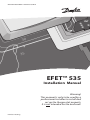
MAKING MODERN LIVING POSSIBLE
INT
INT
EFET™ 535
Installation Manual
Warning!
This manual is only to be used by a
professional installer to install and
set up the thermostat properly.
It is not intended for the end-user!
Danfoss Heating
Congratulations with…
... your Danfoss floor heating system
Your property has been installed with a Danfoss electric floor
heating system. Danfoss is Europe’s leading floor heating
manufacturer, with over 45 years experience. We are confident that you will be satisfied with your new system.
Danfoss brings you…
An Invisible heating solution - A concealed heat source opens
up greater opportunities for decorating and furnishing.
Optimum comfort - Danfoss brings you the luxury and
comfort of a warm floor as well as a pleasant room temperature. Floor heating is the most comfortable type of heating
because it is based on the fact that warmth travels upwards;
pleasant warmth for your feet, body and head.
Low running costs – Thanks to the precise Danfoss thermostat and the placement of the heating elements right under
the floor surface the heat can be controlled optimally in
order for you to have the comfort you desire with minimal
energy use. Moreover electric floor heating is practically
maintenance free, in total keeping down the running costs.
A long lasting solution - We back-up our floor heating solutions with a ten year guarantee on all our mats and cables,
and a two year warranty on our thermostats. Practically
speaking you can count on Danfoss heating cables and mats
lasting as long as the house in which they are installed – and
that is without having to maintain them.
Hygiene - As Danfoss produce floor heating systems, only
very gentle air is circulating, and the amount of travelling
dust particles is reduced considerably; a great relief for
people with allergies or asthma. There are also no dangerous
fumes such as carbon monoxide generated by the system.
2
Table
Table of
of content
content
Install & configure the thermostat . . . . . . . . . . . . . . . . . . . . . .4
Placement of EFETTM 535 . . . . . . . . . . . . . . . . . . . . . . . . . . 4
Installation of EFETTM 535 . . . . . . . . . . . . . . . . . . . . . . . . . . 5
User’s guide to EFETTM 535 . . . . . . . . . . . . . . . . . . . . . . . . . . . 10
Introduction . . . . . . . . . . . . . . . . . . . . . . . . . . . . . . . . . . . . . 10
Display, icons and buttons . . . . . . . . . . . . . . . . . . . . . . . 10
Increase / decrease preferred temperature. . . . . . . . 11
Using the timer function . . . . . . . . . . . . . . . . . . . . . . . . . 12
Settings . . . . . . . . . . . . . . . . . . . . . . . . . . . . . . . . . . . . . . . . . . 14
Setting the time . . . . . . . . . . . . . . . . . . . . . . . . . . . . . . 16
Setting the weekday . . . . . . . . . . . . . . . . . . . . . . . . . . 17
Setting the timer periods . . . . . . . . . . . . . . . . . . . . . . 18
Setting the comfort temperature . . . . . . . . . . . . . . 19
Setting the savings temperature . . . . . . . . . . . . . . 19
Setting the minimum floor temperature limit . . 19
Special features . . . . . . . . . . . . . . . . . . . . . . . . . . . . . . . . . . 20
Childproof mode . . . . . . . . . . . . . . . . . . . . . . . . . . . . . 20
Frost protection mode . . . . . . . . . . . . . . . . . . . . . . . . 20
OFF mode . . . . . . . . . . . . . . . . . . . . . . . . . . . . . . . . . . . . 21
Restore timer default settings . . . . . . . . . . . . . . . . . 21
Switching displayed temperature . . . . . . . . . . . . . 22
Trouble shooting . . . . . . . . . . . . . . . . . . . . . . . . . . . . . . . . . 23
Technical Specifications . . . . . . . . . . . . . . . . . . . . . . . . . . . . . . 24
Disposal Instruction . . . . . . . . . . . . . . . . . . . . . . . . . . . . . . . . . . 25
The Danfoss Guarantee . . . . . . . . . . . . . . . . . . . . . . . . . . . . . . 26
INT
3
Install & configure the thermostat
Placement of EFETTM 535
When EFETTM 535 is used as a room
sensor, installation height should typically be
between 80-150 cm.
In wet rooms it should be installed on an even
surface, according to local building regulations.
At least 50 cm away from windows/doors that
will be left open occasionally.
Not on a wall where it will be subjected to
direct sunlight.
Not on the inner side of a wall facing the
outside.
4
Installation and connection
Installation of EFETTM 535
1. To remove the front cover, gently press the release tabs under the bottom of the thermostat with a screwdriver. Then remove the front.
INT
Removing the front cover and
pushing the installation button,
is not intended to be done by
anyone else but a qualified
installer!
Max.
Load
15 A
NO
CONNECT
Mains
180-250V~
NL
Sensor
2. Connect the thermostat according to the connection
diagram
N
L
N Load L Load NTC
The screen of the heating cable must be connected via a
terminal strip to the earth wire of the supply cable.
5
Choose sensor combination
3.
Choose sensor combination
When installing the EFET™ 535 you need to choose
the type of heating and thus which sensors should be used. You have three options:
Comfort heating: Constant temperature on the floor in bathrooms and other rooms where a comfortable warm
surface is required.
Install the Floor sensor and choose only the Floor sensor.
Total heating: Control of room temperature in living
rooms etc. Install the Floor sensor and choose both
Floor sensor and Room sensor.
No floor sensor: A floor sensor is not present, and
cannot be installed. Choose Room sensor. (Not recommended).
Be aware that without a floor sensor, the temperature control can be less accurate, and overheating of the floor is of higher risk.
Danfoss recommends that a floor sensor is always
installed.
When the thermostat is used to control a floor heating
element according to EN/IEC 60335-1 and
EN/IEC 60335-2-96, always use the floor sensor
and never set the temperature limit above 35°C.
6
Configuration - sensor
Selection of sensor type
Power on the thermostat.
With the front off, with a small screwdriver, pencil, or needle press the
installation button.
Select the sensors to be used for the
heating system:
EFETTM 535 is able to use two
sensors:
- a built-in room sensor
- an external sensor to be placed in the floor.
This gives 3 options:
floor sensor.
room sensor.
both room and floor sensor.
Always use floor sensor or a room
+ floor sensor combination when
used to control floor heating
The default is
To change this setting, press • and
use the arrow buttons ▲▼ to select
your choice. Press • to accept your
choice.
If you have selected room sensor
only, the installation procedure is
complete. Press installation button
to accept. (Go to page 9).
If you have selected floor sensor or a
combination of room- and floor sensor press ▲▼ for the next setting.
7
INT
Configuration - Max. floor temp.
Maximum floor temperature.
When selecting either floor
sensor or
floor and room
sensors, next screen is maximum
floor temperature.
Default setting is 35°C.
To change this setting, press • and
use the arrow buttons ▲▼ to select
your choice. Press • to accept your
choice.
If you have selected a combination of
room and floor sensor, the installation procedure is complete.
Press installation button to accept.
(Go to page 9)
If you have selected floor sensor only
press ▲▼ for the next setting.
When the thermostat is used to control a floor heating
element according to EN/IEC 60335-1 and
EN/IEC 60335-2-96, always use the floor sensor
and never set the temperature limit above 35°C.
Notice:
The floor temperature is measured where the sensor is
placed. The temperature of the bottom of a wooden floor
can be up to 10 degrees higher than the top. Floor manufactures often specify the max. temperature on the top
surface of the floor.
Please contact your floor supplier for maximum surface
temperature.
8
Configuration - Scale
Scale
If you select EFETTM 535 to only use
a floor sensor, mode , you have to
select the display type. The choice is
either numerical scale 1-6 or Celcius
scale 5° to 45°.
Default is Celcius scale. When selecting Celcius, the display will show
the actual temperature at the floor
sensor.
To change this setting, press • and
use the arrow buttons ▲▼ to select
your choice.
Press • to accept your choice.
The installation procedure is now
finished.
You can use the ▲▼ for going back or
forward through the settings.
Otherwise:
Press the installation pinhole to exit
installation mode.
4. Put the frame and front back on.
Initially mains supply the thermostat for 15 hours to
fully charge the battery. The current time and day
is then kept for 80 days if mains supply is off.
All other settings are stored permanently.
9
INT
User’s guide to EFET TM 535
EFETTM 535 Introduction
EFETTM 535 is an electronic timer temperature controller,
specially designed for floor heating systems.
The EFETTM 535, once set, automatically adjusts the
heating to meet your comfort levels, regardless of changing
weather conditions by measuring the floor temperature and
combining it with the air temperature.
Even the programming of economy temperatures (i.e. lowering of temperature during the night and when you are out of
the house) is very simple. Just tell the EFETTM 535 your daily
rhythm and choose your program.
It also features a minimum floor temp. setting, eg. for
keeping your tile floors warm in summer as well.
Display, icons and buttons
This is the standard display. The
currently measured temperature is
shown.
is shown to symbolize that current
temperature is displayed, i.e. unit
working as a thermometer.
This is a safety
switch, meaing all
electrical supply to
the thermostat is
disconnected when
turned off.
10
The thermostat is operated with the
3 buttons below the display.
▼ down
▲ up
• select
Two pinhole buttons are available for
dedicated features
Childproof. Locks all buttons.
Settings.
Increase / decrease temperature
The display indicates:
Weekdays
Childproof
Frost protection
Actual
temperature
is displayed
Settings
Room
temperature
INT
Floor
temperature
Day rhythm periods
and comfort / economy temperature
Maximum / Minimum
Increase / decrease preferred temperature.
Use the arrow buttons ▲▼ to either increase
or decrease the temperature. The temperature is changed in increments of 0.1°C.
Notice that the temperature is flashing.
Whenever something is flashing you are
making changes.
When the preferred temperature is found
you can save the setting in two ways
- Press • to accept
- Leaving it flashing for 10 seconds.
If you try to increase the set point above
the max. floor limit (p. 8) when thermostat
is operating only on floor temperature, this
icon will flash
11
Timer function
Using the timer function
The thermostat has a built-in timer function. A status bar in
the bottom of the display gives an overview of timer status.
Night
Evening
Day
Morning
The day is divided into 4 time periods
analogous to the typical day programming pattern:
- Morning
- Day
- Evening
- Night
These are indicated by the
as
shown in the picture to the left. The
start time of each of these can be
configured.
The symbol can be:
12
Empty: Indicating that the
thermostat is in economy mode.
Full: Indicating that the
thermostat is in comfort mode.
The 4 programs
4 different programs can be selected
Program 1
Manual mode. The temperature is maintained constantly 24 hours all week.
Program 2
The temperature is lowered to economy
temperature during the day and night
period all week.
INT
P2 is a day program for e.g. working days
where the temperature is decreased during
the middle of the day and at night. In the
morning and evening comfort temperature
is preferred.
Program 3
The temperature is lowered to economy
temperature during the night period all
week.
P3 is a program for days at home where
comfort temperature is preferred during the
day and a savings temperature at night.
Program 4
A week program where:
Mon – Fri: Program 2 and
Sat – Sun: Program 3
P4 is a week program with Monday-Friday as
workdays and Saturday-Sunday as days off.
The top 7 bars indicate Monday through
Sunday. On week days timer program 2 is
used and in weekends timer program 3.
Factory setting is Program 1. Manual mode.
13
Factory settings
The factory setting of the timer is:
Floor
Room
Floor and
sensor only sensor only Room sensor
Temperature:
Comfort
25°C
Economy
5°C
Periods – Day rhythm:
Morning
Day
Evening
Night
21°C
17°C
21°C
17°C
06:00-08:00
08:00-16:00
16:00-22:30
22:30-06:00
You can use the above as it is, or you can change the settings
to match your day pattern. See the chapter Settings – setting
the timer periods, page 18.
Changing timer program
To change the program:
(Remember, you need to set the
time in advance, p.17)
Keep the • button pressed for 2
seconds.
The actual program starts to flash.
It is now possible to change the
program by using the buttons ▲▼
Press • to accept
14
Changing timer program
During the timer programs, P2, P3, and P4,
the flashing
indicates the actual time
period.
In program 4 the actual day is also shown.
Using the arrow buttons ▲▼ in timer mode,
is somewhat different from manual mode.
If you increase/decrease the temperature
in a savings period
this change only
applies to this current period, not any future
savings periods. You might use this if you
are eg. working at home in timer program 4.
If you increase/decrease the tempera-ture
in a comfort period
this change applies
to all future comfort periods, until changed
again. From the perspective that you are
fine tuning the comfort temperature.
15
INT
Settings overview
Settings
All settings are under
following:
the settings menu. Here you set the
- Time
- Weekday
- Timer periods configuration
(Morning, day, evening and night)
- Comfort temperature
- Savings temperature
- Min. floor temperature limit
(Only when combination of room
and floor sensor is installed).
16
Changing the settings
You enter the settings by pressing
the pinhole with a small screw
driver, pencil, or needle, the display
now changes from temperature to
time display.
INT
By using the arrow buttons ▲▼ you
move one way or the other in the
menu.
Setting the time
By pressing the • the hours start flashing, indicating you can change them
with the arrow buttons ▲▼
Press the • again to change the
minutes.
Battery Backup: The current time and
day is kept for 80 days if mains supply
is off. All other settings are stored
permanently. Initially mains supply
the thermostat for 15 hours to fully
charge the battery.
Setting the weekday
By pressing the • the weekday starts
flashing, indicating you can change it
with the arrow buttons ▲▼ Press the •
to accept
17
Changing the settings
Setting the timer periods
When programming the starting times of the 4
periods keep in mind that the thermostat will
start heating/stop heating at the given time.
Therefore some periods should start and end
before, to compensate for the time it takes to
heat up or down.
The first period bar
flashes indi-cating this
is the morning period.
By pressing the • the start time of the period
starts flashing. You change it with the arrow
buttons ▲▼ in increments of 15 minutes.
Press the • to accept
The second period bar
this is the day period.
flashes indicating
Setting it in the same way.
The third period bar
is the evening period.
flashes indicating this
Setting it in the same way.
The fourth period bar
this is the night period.
flashes indicating
Setting it in the same way.
Note! When setting the time periods you cannot step backward to the previous time period, until the last one is set. This
is to ensure that the periods do not overlap.
18
Changing the settings
Setting the comfort
temperature
By pressing the • the preset comfort temperature starts flashing.
You change it with the arrow
buttons ▲▼
INT
Press the • to accept
Setting the savings
temperature
By pressing the • the preset savings temperature
starts flashing. You change it with the arrow
buttons ▲▼
Press the • to accept
It can also be set to OFF.
Setting the minimum floor
temperature limit
If the thermostat is installed as a combination
of room and floor sensor the minimum comfort
temperature on the floor can be selected.
Setting this will overrule any other set point as
you always want e.g. 20°C at the floor sensor
--.-° means that the function is disabled.
By pressing the • the preset minimum floor limit
temperature starts flashing.
You change it with the arrow ▲▼
Press the • to accept
19
Special features
Childproof mode
You disable all buttons in child proof
mode by pressing the pinhole button
below with a small screw driver,
pencil, or needle.
A lock now appears in the display and
all other buttons are locked now.
To unlock press the lock symbol again
Frost protection mode
To set the thermostat in frost protection mode, you hold down ▼ until you
reach the lowest setting. Now press
▼ again to verify that you are not just
changing the comfort or economy
temperature, depending on the mode
or timer period the thermostat is in.
The frost icon now appears and 5.0°
flashes.
You accept the mode by
- Press • to accept
- Leaving it flashing for 10 seconds.
The thermostat is now in frost protected mode. Actual temperature is
shown.
You leave frost protection mode by
pressing ▲ (0.5sec).
20
Special features
OFF mode
To set the thermostat in OFF mode,
you hold down ▼ until you reach 5.0°.
Now press ▼ again twice to verify that
you are not just changing the comfort
or economy temperature, depending on the mode or timer period the
thermostat is in.
The display now shows OFF.
You accept the mode by
- Press • to accept
- Leaving it flashing for 10 seconds.
OFF mode is used if you want to shut
off the thermostat for a long period,
but still keeping the time setting.
The thermostat is now in OFF mode.
Two lines are shown in the display.
You leave OFF mode by pressing ▲
(0.5sec).
Restore timer default settings
To reset the thermostat to its timer
defaults as shown on page 14, do the
following:
1. Turn off the thermostat
2. While pressing the pinhole button,
turn on the thermostat. The LED will
now flash red/green for 1 second
indicating the thermostat will reset.
21
INT
Special features / Trouble shooting
Switching displayed temperature
Depending on what mode the thermostat is
installed as (floor, or a combination of floor and
room) you can change which temperature is
displayed.
If installed as a floor sensor system only, you can
change the displayed temperature from floor
sensor temperature to room sensor temperature, if you wish to use the thermostat as a
thermometer. You change the display by
pressing ▲ and ▼ at the same time for 2 seconds.
The room sensor icon is displayed.
You press them again to return to the default
display.
If installed as a combination thermostat, by
pressing ▲ and ▼ at the same time for 2 seconds,
the temperature in the floor sensor is displayed
for 2 minutes. The floor sensor icon is
displayed.
Trouble shooting
Clock symbol flashing:
Time settings were lost due to power cut.
The thermostat resumes to manual mode.
22
Trouble shooting
E4 flashing in display:
Error code 4 – The thermostat has overheated
and has switched off
Let the thermostat cool for period. Then switch
the thermostat off and on.
INT
E5 or E6 flashing in display:
Error code 5 - Floor sensor short circuited
Error code 6 - Floor sensor disconnected.
Check connections, if they are OK, then disconnect the 2 sensor wires and connect an ohm
meter to sensor wires.
Measure the ohm value and check with the values in the table in Technical Specifications below.
Light Indications (LED)
The EFETTM 535 has a LED above the 2 pole safety switch.
The LED has five indications:
No light
Green light
Green light flashing
Red light
Switching between
red and green light
The system is turned off.
System is standing by, set point
temperature reached
Floor sensor is defect
System is heating
The floor temperature limit prevents the set point room temperature from being reached.
23
Technical specifications
Operation voltage
Standby power
consumption
Relay:
• Resistive load
• Inductive load
Sensing unit
Sensing values:
• 0°C
• 20°C
• 50°C
Hysteresis
180-250 VAC, 50/60 Hz
Max. 0.30 W
230V ~ 15A / 3450W
cos φ= 0.3 Max. 4A
NTC 15 kOhm at 25°C
42 kOhm
18 kOhm
6 kOhm
± 0.2°C with room sensor,
± 0.4°C with floor sensor only
-10° to +30°C
Ambient temperature
Frost protection
5°C
Temperature range 5-35°C with room sensor,
5-45°C with floor sensor only.
When used together with electrical
floor heating elements, according to
EN/IEC 60335-2-96 never adjust floor
temperature above 35°C.
Floor max. 20-50°C.
Floor min. 10-35°C only when
installed with room and floor
sensor combination
Sensor failure
The thermostat has a built-in monitormonitoring
ing circuit, which will switch off the
heating if the sensor is disconnected
or short-circuited
IP class
31
Dimensions
85 mm x 85 mm
24
Disposal Instruction
All electric or electronic equipment and enclosed batteries
containing materials, components and substances that can
be harmful to people’s healthiness and to the environment, if
the waste is not handled correctly.
All electric or electronic equipment and batteries is marked
with the below crossed sign of a dustbin or garbage can. This INT
sign symbolize electric or electronic equipment and batteries
which are not allowed to be removed or disposed together
with the unsorted waste, but have to be gathered individually.
Some batteries are also marked with a chemical symbol Hg
(mercury), Cd (cadmium) or Pb (lead). These are very harmful
substances and for this reason it is very important to collect
these batteries.
As end user it is important for you to hand in your used
batteries for recycling. In this way you actively take part to
ensure that the batteries are reused according to the law and
do not unnecessary impact on the environment.
All countries have established collecting
points or other collecting arrangements,
where citizens free of charge can deliver
scraped electrical and electronic equipment
together with batteries for recycling. More
information can be obtained at your local
authorities.
25
The 2 Year Danfoss Warranty:
You have purchased a Danfoss heating system which we are sure will
serve to improve the comfort and economy of your application.
Danfoss provides superior electrical heating solutions for total climate
control in and around homes and buildings. Danfoss offers a complete
product program with ECFLEX heating cable or ECMAT heating mat,
ECTEMP thermostats and Danfoss selflimiting heating cable combined
with additional products completing the product program.
This 2 year warranty applies to all Danfoss products.
Should you, against all expectations, experience a problem with your
Danfoss product, you will find that Danfoss offers a 2 year warranty
from the date of purchase on the following conditions:
During the warranty period Danfoss shall offer a new comparable
product or repair the product in case the product is found to be faulty
by reason of defective design, materials or workmanship. Repair or
replacement shall be carried out at Danfoss’s discretion. Danfoss shall
not be liable for any consequential or incidental damages including,
but not limited to, damages to property or extra utility expenses.
This warranty shall only be valid on production of proof of purchase
and must be submitted to the installer or seller without undue delay.
An extension of the warranty period following repairs undertaken
under warranty cannot be granted.
The Danfoss Warranty shall not cover any damage caused by incorrect
conditions of use, incorrect installation or if installation has been
carried out by non-authorised electricians. All work will be invoiced in
full if Danfoss is required to inspect or repair faults that have arisen as a
result of any of the above.
The Danfoss Warranty shall not extend to equipment which has not
been paid in full.
Danfoss will, at all times, provide a rapid and effective response to all
complaints and inquiries from our customers.
The warranty explicitly excludes all claims exceeding the above
conditions.
26
2 YEAR WARRANTY
Warranty Certificate
The Danfoss Guarantee is granted to:
Name:
Address:
City:
INT
Country:
Telephone:
Attention:
The Warranty Certificate must be completed correctly for
the Warranty to be valid.
Please read the Warranty conditions on the previous page.
Type of thermostat:
Material number:
Electrical installation by:
Date:
Suppliers Stamp
Date /
-
27
Article No.: 088L4374
Version - 01.01
Danfoss A/S
Ulvehavevej 61
DK-7100 Vejle
Tel: +45 74 88 85 00
Fax: +45 74 88 85 01
www.danfoss.com
Danfoss Heating Solutions
VIFZB102
© Danfoss 09/2009