1
ServerView Resource Orchestrator
Virtual Edition V3.0.0
Setup Guide
Windows/Linux
J2X1-7604-01ENZ0(05)
April 2012
Preface
Purpose
This manual provides an outline of ServerView Resource Orchestrator (hereinafter Resource Orchestrator) and the operations and settings
required for setup.
Target Readers
This manual is written for people who will install Resource Orchestrator.
When setting up systems, it is assumed that readers have the basic knowledge required to configure the servers, storage, and network
devices to be installed.
Organization
This manual is composed as follows:
Title
Description
Chapter 1 Overview
Provides an overview of Resource Orchestrator.
Chapter 2 Overview of Resource Orchestrator
Setup Operations
Explains the overall flow of setup operations when using Resource
Orchestrator.
Chapter 3 Resource Orchestrator Setup Design
Explains how to design a Resource Orchestrator installation.
Chapter 4 Pre-setup Preparations
Explains how to design and prepare a Resource Orchestrator installation.
Chapter 5 Installation and Uninstallation
Explains how to install and uninstall Resource Orchestrator.
Chapter 6 Configuration After Installation
Explains configuration after installing Resource Orchestrator.
Chapter 7 Resource Orchestrator login
Explains how to log in to Resource Orchestrator.
Chapter 8 Setup
Explains how to set up Resource Orchestrator after installation.
Appendix A Port List
Describes the ports used by Resource Orchestrator.
Appendix B HTTPS Communications
Explains the security features of the HTTPS communication protocol
used by Resource Orchestrator.
Appendix C Hardware Configuration
Explains how to configure hardware.
Appendix D Coordination with Other Products
Explains how to coordinate use of Resource Orchestrator and other
products.
Appendix E Server Virtualization Products
Explains the functions available for each server virtualization product
managed in Resource Orchestrator.
Appendix F Notes on Installation
Explains points to keep in mind when setting up a Resource Orchestrator
environment.
Appendix G Co-Existence with ServerView
Deployment Manager
Explains how to use both Resource Orchestrator and ServerView
Deployment Manager on the same network.
Glossary
Explains the terms used in this manual. Please refer to it when necessary.
Notational Conventions
The notation in this manual conforms to the following conventions.
- When using Resource Orchestrator and the functions necessary differ due to the necessary basic software (OS), it is indicated as
follows:
-i-
[Windows]
Sections related to Windows (When not using Hyper-V)
[Linux]
Sections related to Linux
[Red Hat Enterprise Linux]
Sections related to Red Hat Enterprise Linux
[Solaris]
Sections related to Solaris
[VMware]
Sections related to VMware
[Hyper-V]
Sections related to Hyper-V
[Xen]
Sections related to Xen
[KVM]
Sections related to RHEL-KVM
[Solaris Containers]
Sections related to Solaris containers
[Windows/Hyper-V]
Sections related to Windows and Hyper-V
[Windows/Linux]
Sections related to Windows and Linux
[Linux/VMware]
Sections related to Linux and VMware
[Linux/Xen]
Sections related to Linux and Xen
[Xen/KVM]
Sections related to Xen and RHEL-KVM
[Linux/Solaris/VMware]
Sections related to Linux, Solaris, and VMware
[Linux/VMware/Xen]
Sections related to Linux, VMware, and Xen
[Linux/Xen/KVM]
Sections related to Linux, Xen, and RHEL-KVM
[VMware/Hyper-V/Xen]
Sections related to VMware, Hyper-V, and Xen
[Linux/Solaris/VMware/Xen]
Sections related to Linux, Solaris, VMware, and Xen
[Linux/VMware/Xen/KVM]
Sections related to Linux, VMware, Xen, and RHEL-KVM
[VMware/Hyper-V/Xen/KVM]
Sections related to VMware, Hyper-V, Xen, and RHEL-KVM
[Linux/Solaris/VMware/Xen/KVM]
Sections related to Linux, Solaris, VMware, Xen, and RHEL-KVM
[VM host]
Sections related to VMware, Windows Server 2008 with Hyper-V enabled,
Xen, RHEL-KVM, and Solaris containers
- Unless specified otherwise, the blade servers mentioned in this manual refer to PRIMERGY BX servers.
- Oracle Solaris may also be indicated as Solaris, Solaris Operating System, or Solaris OS.
- References and character strings or values requiring emphasis are indicated using double quotes ( " ).
- Window names, dialog names, menu names, and tab names are shown enclosed by brackets ( [ ] ).
- Button names are shown enclosed by angle brackets (< >) or square brackets ([ ]).
- The order of selecting menus is indicated using [ ]-[ ].
- Text to be entered by the user is indicated using bold text.
- Variables are indicated using italic text and underscores.
- The ellipses ("...") in menu names, indicating settings and operation window startup, are not shown.
Menus in the ROR console
Operations on the ROR console can be performed using either the menu bar or pop-up menus.
By convention, procedures described in this manual only refer to pop-up menus.
Documentation Road Map
The following manuals are provided with Resource Orchestrator. Please refer to them when necessary:
- ii -
Manual Name
Abbreviated Form
Purpose
Please read this first.
ServerView Resource Orchestrator Virtual
Edition V3.0.0 Setup Guide
Setup Guide VE
ServerView Resource Orchestrator Virtual
Edition V3.0.0 Installation Guide
Installation Guide VE
Read this when you want information about how
to install Resource Orchestrator.
ServerView Resource Orchestrator Virtual
Edition V3.0.0 Operation Guide
Operation Guide VE
Read this when you want information about how
to operate systems that you have configured.
ServerView Resource Orchestrator Virtual
Edition V3.0.0 User's Guide
User's Guide VE
Read this when you want information about how
to operate the GUI.
ServerView Resource Orchestrator Virtual
Edition V3.0.0 Command Reference
Command Reference
Read this when you want information about how
to use commands.
ServerView Resource Orchestrator Virtual
Edition V3.0.0 Messages
Messages VE
Read this when you want detailed information
about the corrective actions for displayed
messages.
Read this when you want information about the
purposes and uses of basic functions, and how to
install Resource Orchestrator.
Related Documentation
Please refer to these manuals when necessary.
- SPARC Enterprise - ETERNUS SAN Boot Environment Build Guide
Abbreviations
The following abbreviations are used in this manual:
Abbreviation
Products
Windows
Microsoft(R) Windows Server(R) 2008 Standard
Microsoft(R) Windows Server(R) 2008 Enterprise
Microsoft(R) Windows Server(R) 2008 R2 Standard
Microsoft(R) Windows Server(R) 2008 R2 Enterprise
Microsoft(R) Windows Server(R) 2008 R2 Datacenter
Microsoft(R) Windows Server(R) 2003 R2, Standard Edition
Microsoft(R) Windows Server(R) 2003 R2, Enterprise Edition
Microsoft(R) Windows Server(R) 2003 R2, Standard x64 Edition
Microsoft(R) Windows Server(R) 2003 R2, Enterprise x64 Edition
Windows(R) 7 Professional
Windows(R) 7 Ultimate
Windows Vista(R) Business
Windows Vista(R) Enterprise
Windows Vista(R) Ultimate
Microsoft(R) Windows(R) XP Professional operating system
Windows Server 2008
Microsoft(R) Windows Server(R) 2008 Standard
Microsoft(R) Windows Server(R) 2008 Enterprise
Microsoft(R) Windows Server(R) 2008 R2 Standard
Microsoft(R) Windows Server(R) 2008 R2 Enterprise
Microsoft(R) Windows Server(R) 2008 R2 Datacenter
Windows 2008 x86 Edition
Microsoft(R) Windows Server(R) 2008 Standard (x86)
Microsoft(R) Windows Server(R) 2008 Enterprise (x86)
- iii -
Abbreviation
Products
Windows 2008 x64 Edition
Microsoft(R) Windows Server(R) 2008 Standard (x64)
Microsoft(R) Windows Server(R) 2008 Enterprise (x64)
Windows Server 2003
Microsoft(R) Windows Server(R) 2003 R2, Standard Edition
Microsoft(R) Windows Server(R) 2003 R2, Enterprise Edition
Microsoft(R) Windows Server(R) 2003 R2, Standard x64 Edition
Microsoft(R) Windows Server(R) 2003 R2, Enterprise x64 Edition
Windows 2003 x64 Edition
Microsoft(R) Windows Server(R) 2003 R2, Standard x64 Edition
Microsoft(R) Windows Server(R) 2003 R2, Enterprise x64 Edition
Windows 7
Windows(R) 7 Professional
Windows(R) 7 Ultimate
Windows Vista
Windows Vista(R) Business
Windows Vista(R) Enterprise
Windows Vista(R) Ultimate
Windows XP
Microsoft(R) Windows(R) XP Professional operating system
Windows PE
Microsoft(R) Windows(R) Preinstallation Environment
Linux
Red Hat(R) Enterprise Linux(R) AS (v.4 for x86)
Red Hat(R) Enterprise Linux(R) ES (v.4 for x86)
Red Hat(R) Enterprise Linux(R) AS (v.4 for EM64T)
Red Hat(R) Enterprise Linux(R) ES (v.4 for EM64T)
Red Hat(R) Enterprise Linux(R) AS (4.5 for x86)
Red Hat(R) Enterprise Linux(R) ES (4.5 for x86)
Red Hat(R) Enterprise Linux(R) AS (4.5 for EM64T)
Red Hat(R) Enterprise Linux(R) ES (4.5 for EM64T)
Red Hat(R) Enterprise Linux(R) AS (4.6 for x86)
Red Hat(R) Enterprise Linux(R) ES (4.6 for x86)
Red Hat(R) Enterprise Linux(R) AS (4.6 for EM64T)
Red Hat(R) Enterprise Linux(R) ES (4.6 for EM64T)
Red Hat(R) Enterprise Linux(R) AS (4.7 for x86)
Red Hat(R) Enterprise Linux(R) ES (4.7 for x86)
Red Hat(R) Enterprise Linux(R) AS (4.7 for EM64T)
Red Hat(R) Enterprise Linux(R) ES (4.7 for EM64T)
Red Hat(R) Enterprise Linux(R) AS (4.8 for x86)
Red Hat(R) Enterprise Linux(R) ES (4.8 for x86)
Red Hat(R) Enterprise Linux(R) AS (4.8 for EM64T)
Red Hat(R) Enterprise Linux(R) ES (4.8 for EM64T)
Red Hat(R) Enterprise Linux(R) 5 (for x86)
Red Hat(R) Enterprise Linux(R) 5 (for Intel64)
Red Hat(R) Enterprise Linux(R) 5.1 (for x86)
Red Hat(R) Enterprise Linux(R) 5.1 (for Intel64)
Red Hat(R) Enterprise Linux(R) 5.2 (for x86)
Red Hat(R) Enterprise Linux(R) 5.2 (for Intel64)
Red Hat(R) Enterprise Linux(R) 5.3 (for x86)
Red Hat(R) Enterprise Linux(R) 5.3 (for Intel64)
Red Hat(R) Enterprise Linux(R) 5.4 (for x86)
Red Hat(R) Enterprise Linux(R) 5.4 (for Intel64)
Red Hat(R) Enterprise Linux(R) 5.5 (for x86)
Red Hat(R) Enterprise Linux(R) 5.5 (for Intel64)
Red Hat(R) Enterprise Linux(R) 5.6 (for x86)
Red Hat(R) Enterprise Linux(R) 5.6 (for Intel64)
Red Hat(R) Enterprise Linux(R) 5.7 (for x86)
Red Hat(R) Enterprise Linux(R) 5.7 (for Intel64)
Red Hat(R) Enterprise Linux(R) 6 (for x86)
Red Hat(R) Enterprise Linux(R) 6 (for Intel64)
- iv -
Abbreviation
Products
Red Hat(R) Enterprise Linux(R) 6.1 (for x86)
Red Hat(R) Enterprise Linux(R) 6.1 (for Intel64)
Red Hat(R) Enterprise Linux(R) 6.2 (for x86)
Red Hat(R) Enterprise Linux(R) 6.2 (for Intel64)
SUSE(R) Linux Enterprise Server 10 Service Pack2 for x86
SUSE(R) Linux Enterprise Server 10 Service Pack2 for EM64T
SUSE(R) Linux Enterprise Server 10 Service Pack3 for x86
SUSE(R) Linux Enterprise Server 10 Service Pack3 for EM64T
SUSE(R) Linux Enterprise Server 11 for x86
SUSE(R) Linux Enterprise Server 11 for EM64T
SUSE(R) Linux Enterprise Server 11 Service Pack1 for x86
SUSE(R) Linux Enterprise Server 11 Service Pack1 for EM64T
Oracle Enterprise Linux Release 5 Update 4 for x86 (32 Bit)
Oracle Enterprise Linux Release 5 Update 4 for x86_64 (64 Bit)
Oracle Enterprise Linux Release 5 Update 5 for x86 (32 Bit)
Oracle Enterprise Linux Release 5 Update 5 for x86_64 (64 Bit)
Red Hat Enterprise Linux
Red Hat(R) Enterprise Linux(R) AS (v.4 for x86)
Red Hat(R) Enterprise Linux(R) ES (v.4 for x86)
Red Hat(R) Enterprise Linux(R) AS (v.4 for EM64T)
Red Hat(R) Enterprise Linux(R) ES (v.4 for EM64T)
Red Hat(R) Enterprise Linux(R) AS (4.5 for x86)
Red Hat(R) Enterprise Linux(R) ES (4.5 for x86)
Red Hat(R) Enterprise Linux(R) AS (4.5 for EM64T)
Red Hat(R) Enterprise Linux(R) ES (4.5 for EM64T)
Red Hat(R) Enterprise Linux(R) AS (4.6 for x86)
Red Hat(R) Enterprise Linux(R) ES (4.6 for x86)
Red Hat(R) Enterprise Linux(R) AS (4.6 for EM64T)
Red Hat(R) Enterprise Linux(R) ES (4.6 for EM64T)
Red Hat(R) Enterprise Linux(R) AS (4.7 for x86)
Red Hat(R) Enterprise Linux(R) ES (4.7 for x86)
Red Hat(R) Enterprise Linux(R) AS (4.7 for EM64T)
Red Hat(R) Enterprise Linux(R) ES (4.7 for EM64T)
Red Hat(R) Enterprise Linux(R) AS (4.8 for x86)
Red Hat(R) Enterprise Linux(R) ES (4.8 for x86)
Red Hat(R) Enterprise Linux(R) AS (4.8 for EM64T)
Red Hat(R) Enterprise Linux(R) ES (4.8 for EM64T)
Red Hat(R) Enterprise Linux(R) 5 (for x86)
Red Hat(R) Enterprise Linux(R) 5 (for Intel64)
Red Hat(R) Enterprise Linux(R) 5.1 (for x86)
Red Hat(R) Enterprise Linux(R) 5.1 (for Intel64)
Red Hat(R) Enterprise Linux(R) 5.2 (for x86)
Red Hat(R) Enterprise Linux(R) 5.2 (for Intel64)
Red Hat(R) Enterprise Linux(R) 5.3 (for x86)
Red Hat(R) Enterprise Linux(R) 5.3 (for Intel64)
Red Hat(R) Enterprise Linux(R) 5.4 (for x86)
Red Hat(R) Enterprise Linux(R) 5.4 (for Intel64)
Red Hat(R) Enterprise Linux(R) 5.5 (for x86)
Red Hat(R) Enterprise Linux(R) 5.5 (for Intel64)
Red Hat(R) Enterprise Linux(R) 5.6 (for x86)
Red Hat(R) Enterprise Linux(R) 5.6 (for Intel64)
Red Hat(R) Enterprise Linux(R) 5.7 (for x86)
Red Hat(R) Enterprise Linux(R) 5.7 (for Intel64)
Red Hat(R) Enterprise Linux(R) 6 (for x86)
Red Hat(R) Enterprise Linux(R) 6 (for Intel64)
Red Hat(R) Enterprise Linux(R) 6.1 (for x86)
Red Hat(R) Enterprise Linux(R) 6.1 (for Intel64)
-v-
Abbreviation
Products
Red Hat(R) Enterprise Linux(R) 6.2 (for x86)
Red Hat(R) Enterprise Linux(R) 6.2 (for Intel64)
Red Hat Enterprise Linux 5
Red Hat(R) Enterprise Linux(R) 5 (for x86)
Red Hat(R) Enterprise Linux(R) 5 (for Intel64)
Red Hat(R) Enterprise Linux(R) 5.1 (for x86)
Red Hat(R) Enterprise Linux(R) 5.1 (for Intel64)
Red Hat(R) Enterprise Linux(R) 5.2 (for x86)
Red Hat(R) Enterprise Linux(R) 5.2 (for Intel64)
Red Hat(R) Enterprise Linux(R) 5.3 (for x86)
Red Hat(R) Enterprise Linux(R) 5.3 (for Intel64)
Red Hat(R) Enterprise Linux(R) 5.4 (for x86)
Red Hat(R) Enterprise Linux(R) 5.4 (for Intel64)
Red Hat(R) Enterprise Linux(R) 5.5 (for x86)
Red Hat(R) Enterprise Linux(R) 5.5 (for Intel64)
Red Hat(R) Enterprise Linux(R) 5.6 (for x86)
Red Hat(R) Enterprise Linux(R) 5.6 (for Intel64)
Red Hat(R) Enterprise Linux(R) 5.7 (for x86)
Red Hat(R) Enterprise Linux(R) 5.7 (for Intel64)
Red Hat Enterprise Linux 6
Red Hat(R) Enterprise Linux(R) 6 (for x86)
Red Hat(R) Enterprise Linux(R) 6 (for Intel64)
Red Hat(R) Enterprise Linux(R) 6.1 (for x86)
Red Hat(R) Enterprise Linux(R) 6.1 (for Intel64)
Red Hat(R) Enterprise Linux(R) 6.2 (for x86)
Red Hat(R) Enterprise Linux(R) 6.2 (for Intel64)
RHEL-KVM
Red Hat(R) Enterprise Linux(R) 6.1 (for x86) Virtual Machine Function
Red Hat(R) Enterprise Linux(R) 6.1 (for Intel64) Virtual Machine Function
Red Hat(R) Enterprise Linux(R) 6.2 (for x86) Virtual Machine Function
Red Hat(R) Enterprise Linux(R) 6.2 (for Intel64) Virtual Machine Function
Xen
Citrix XenServer(TM) 5.5
Citrix Essentials(TM) for XenServer 5.5, Enterprise Edition
Red Hat(R) Enterprise Linux(R) 5.3 (for x86) Linux Virtual Machine Function
Red Hat(R) Enterprise Linux(R) 5.3 (for Intel64) Linux Virtual Machine Function
Red Hat(R) Enterprise Linux(R) 5.4 (for x86) Linux Virtual Machine Function
Red Hat(R) Enterprise Linux(R) 5.4 (for Intel64) Linux Virtual Machine Function
Red Hat(R) Enterprise Linux(R) 5.5 (for x86) Linux Virtual Machine Function
Red Hat(R) Enterprise Linux(R) 5.5 (for Intel64) Linux Virtual Machine Function
Red Hat(R) Enterprise Linux(R) 5.6 (for x86) Linux Virtual Machine Function
Red Hat(R) Enterprise Linux(R) 5.6 (for Intel64) Linux Virtual Machine Function
Red Hat(R) Enterprise Linux(R) 5.7 (for x86) Linux Virtual Machine Function
Red Hat(R) Enterprise Linux(R) 5.7 (for Intel64) Linux Virtual Machine Function
DOS
Microsoft(R) MS-DOS(R) operating system, DR DOS(R)
SUSE Linux Enterprise Server
SUSE(R) Linux Enterprise Server 10 Service Pack2 for x86
SUSE(R) Linux Enterprise Server 10 Service Pack2 for EM64T
SUSE(R) Linux Enterprise Server 10 Service Pack3 for x86
SUSE(R) Linux Enterprise Server 10 Service Pack3 for EM64T
SUSE(R) Linux Enterprise Server 11 for x86
SUSE(R) Linux Enterprise Server 11 for EM64T
SUSE(R) Linux Enterprise Server 11 Service Pack1 for x86
SUSE(R) Linux Enterprise Server 11 Service Pack1 for EM64T
Oracle Enterprise Linux
Oracle Enterprise Linux Release 5 Update 4 for x86 (32 Bit)
Oracle Enterprise Linux Release 5 Update 4 for x86_64 (64 Bit)
Oracle Enterprise Linux Release 5 Update 5 for x86 (32 Bit)
Oracle Enterprise Linux Release 5 Update 5 for x86_64 (64 Bit)
- vi -
Abbreviation
Products
Solaris
Solaris(TM) 10 Operating System
SCVMM
System Center Virtual Machine Manager 2008 R2
System Center 2012 Virtual Machine Manager
VMware
VMware(R) Infrastructure 3
VMware vSphere(R) 4
VMware vSphere(R) 4.1
VMware vSphere(R) 5
VIOM
ServerView Virtual-IO Manager
ServerView Agent
ServerView SNMP Agents for MS Windows (32bit-64bit)
ServerView Agents Linux
ServerView Agents VMware for VMware ESX Server
Excel
Microsoft(R) Office Excel(R) 2010
Microsoft(R) Office Excel(R) 2007
Microsoft(R) Office Excel(R) 2003
Excel 2010
Microsoft(R) Office Excel(R) 2010
Excel 2007
Microsoft(R) Office Excel(R) 2007
Excel 2003
Microsoft(R) Office Excel(R) 2003
ROR VE
ServerView Resource Orchestrator Virtual Edition
ROR CE
ServerView Resource Orchestrator Cloud Edition
Resource Coordinator
Systemwalker Resource Coordinator
Resource Coordinator VE
ServerView Resource Coordinator VE
Systemwalker Resource Coordinator Virtual server Edition
Resource Orchestrator
ServerView Resource Orchestrator
Export Administration Regulation Declaration
Documents produced by FUJITSU may contain technology controlled under the Foreign Exchange and Foreign Trade Control Law of
Japan. Documents which contain such technology should not be exported from Japan or transferred to non-residents of Japan without first
obtaining authorization from the Ministry of Economy, Trade and Industry of Japan in accordance with the above law.
Trademark Information
- BMC, BMC Software, and the BMC Software logo are trademarks or registered trademarks of BMC Software, Inc. in the United
States and other countries.
- Citrix(R), Citrix XenServer(TM), Citrix Essentials(TM), and Citrix StorageLink(TM) are trademarks of Citrix Systems, Inc. and/or
one of its subsidiaries, and may be registered in the United States Patent and Trademark Office and in other countries.
- Dell is a registered trademark of Dell Computer Corp.
- HP is a registered trademark of Hewlett-Packard Company.
- IBM is a registered trademark or trademark of International Business Machines Corporation in the U.S.
- Linux is a trademark or registered trademark of Linus Torvalds in the United States and other countries.
- Microsoft, Windows, MS, MS-DOS, Windows XP, Windows Server, Windows Vista, Windows 7, Excel, and Internet Explorer are
either registered trademarks or trademarks of Microsoft Corporation in the United States and other countries.
- Oracle and Java are registered trademarks of Oracle and/or its affiliates in the United States and other countries.
- Oracle is a registered trademark of Oracle Corporation and/or its affiliates.
- vii -
- Red Hat, RPM and all Red Hat-based trademarks and logos are trademarks or registered trademarks of Red Hat, Inc. in the United
States and other countries.
- Spectrum is a trademark or registered trademark of Computer Associates International, Inc. and/or its subsidiaries.
- SUSE is a registered trademark of SUSE LINUX AG, a Novell business.
- VMware, the VMware "boxes" logo and design, Virtual SMP, and VMotion are registered trademarks or trademarks of VMware, Inc.
in the United States and/or other jurisdictions.
- ServerView and Systemwalker are registered trademarks of FUJITSU LIMITED.
- All other brand and product names are trademarks or registered trademarks of their respective owners.
Notices
- The contents of this manual shall not be reproduced without express written permission from FUJITSU LIMITED.
- The contents of this manual are subject to change without notice.
Month/Year Issued,
Edition
Manual Code
November 2011, First
Edition
J2X1-7604-01ENZ0(00)
December 2011, 1.1
J2X1-7604-01ENZ0(01)
January 2012, 1.2
J2X1-7604-01ENZ0(02)
February 2012, 1.3
J2X1-7604-01ENZ0(03)
March 2012, 1.4
J2X1-7604-01ENZ0(04)
April 2012, 1.5
J2X1-7604-01ENZ0(05)
Copyright FUJITSU LIMITED 2010-2012
- viii -
Contents
Chapter 1 Overview..................................................................................................................................................................1
1.1 Features................................................................................................................................................................................................1
1.2 Function Overview..............................................................................................................................................................................4
1.3 Function Differences Depending on Product.......................................................................................................................................8
1.4 Software Environment.........................................................................................................................................................................9
1.4.1 Software Organization................................................................................................................................................................10
1.4.2 Software Requirements...............................................................................................................................................................10
1.4.2.1 Required Basic Software.....................................................................................................................................................10
1.4.2.2 Required Software...............................................................................................................................................................19
1.4.2.3 Exclusive Software..............................................................................................................................................................23
1.4.2.4 Static Disk Space.................................................................................................................................................................25
1.4.2.5 Dynamic Disk Space............................................................................................................................................................25
1.4.2.6 Memory Size........................................................................................................................................................................29
1.5 Hardware Environment......................................................................................................................................................................29
1.6 System Configuration........................................................................................................................................................................31
Chapter 2 Overview of Resource Orchestrator Setup Operations.........................................................................................34
Chapter 3 Resource Orchestrator Setup Design....................................................................................................................36
3.1 Defining User Accounts.....................................................................................................................................................................36
Chapter 4 Pre-setup Preparations..........................................................................................................................................37
4.1 Defining and Configuring the Server Environment...........................................................................................................................37
4.1.1 Defining the Server Environment...............................................................................................................................................37
4.1.1.1 Chassis Settings (for Blade Server Environments)..............................................................................................................37
4.1.1.2 Settings for Rack Mount or Tower Servers.........................................................................................................................37
4.1.1.3 Chassis Setting Values (For PRIMEQUEST).....................................................................................................................38
4.1.1.4 Settings for SPARC Enterprise (M3000/T Series) Servers.................................................................................................39
4.1.1.5 Chassis Settings (SPARC Enterprise M4000/M5000/M8000/M9000 Servers)..................................................................40
4.1.1.6 Settings for ETERNUS SF Storage Cruiser Integration......................................................................................................40
4.1.2 Configuring the Server Environment..........................................................................................................................................41
4.2 Defining and Configuring the Network Environment.......................................................................................................................45
4.2.1 Network Configuration...............................................................................................................................................................45
4.2.2 IP Addresses (Admin LAN).......................................................................................................................................................56
4.2.3 IP Addresses (iSCSI LAN).........................................................................................................................................................57
4.2.4 Public LAN Settings for Managed Servers.................................................................................................................................57
4.2.5 Network Device Management Settings......................................................................................................................................57
4.2.6 Configuring the Network Environment......................................................................................................................................59
4.3 Deciding and Configuring the Storage Environment........................................................................................................................60
4.3.1 Deciding the Storage Environment.............................................................................................................................................60
4.3.1.1 Storage Configuration..........................................................................................................................................................60
4.3.1.2 HBA and Storage Device Settings.......................................................................................................................................62
4.3.1.3 iSCSI Interface and Storage Device Settings (iSCSI).........................................................................................................64
4.3.2 Configuring the Storage Environment........................................................................................................................................66
4.4 Deciding and Configuring Server Virtualization Software...............................................................................................................66
4.4.1 Deciding Server Virtualization Software....................................................................................................................................67
4.4.2 Configuring Server Virtualization Software...............................................................................................................................67
4.5 Deciding and Configuring the Power Monitoring Environment.......................................................................................................67
4.5.1 Deciding the Power Monitoring Environment............................................................................................................................67
4.5.1.1 Settings for the Power Monitoring Environment.................................................................................................................67
4.5.1.2 Power Monitoring Device Settings......................................................................................................................................68
4.5.2 Configuring the Power Monitoring Environment.......................................................................................................................68
4.6 Installing and Configuring Single Sign-On.......................................................................................................................................68
4.6.1 Deciding the Directory Service to Use.......................................................................................................................................70
4.6.2 Setting up ServerView Operations Manager and Directory Service Environments...................................................................70
- ix -
4.6.3 Preparing Certificates.................................................................................................................................................................71
4.6.4 Registering Administrators.........................................................................................................................................................71
4.6.5 When Reconfiguring Single Sign-On.........................................................................................................................................72
4.6.5.1 Confirming Certificates.......................................................................................................................................................72
4.6.5.2 Registering Certificates........................................................................................................................................................73
4.6.5.3 Checking Directory Service Connection Information.........................................................................................................75
Chapter 5 Installation/Uninstallation.......................................................................................................................................77
Chapter 6 Configuration after Installation...............................................................................................................................78
Chapter 7 Logging in to Resource Orchestrator.....................................................................................................................79
7.1 Login..................................................................................................................................................................................................79
7.2 Starting and Stopping the Manager...................................................................................................................................................81
7.3 Starting and Stopping the Agent........................................................................................................................................................83
Chapter 8 Setup..................................................................................................................................................................... 85
8.1 Registering Resources with Resource Orchestrator...........................................................................................................................85
8.1.1 Managed Resources and Registration Order..............................................................................................................................85
8.2 HBA address rename Settings...........................................................................................................................................................86
8.2.1 Settings for the HBA address rename Setup Service..................................................................................................................89
8.3 Software Installation and Agent Registration....................................................................................................................................91
8.4 Configuring Monitoring Information.................................................................................................................................................93
8.5 Collecting and Registering Cloning Images......................................................................................................................................94
8.6 Saving Environment Settings.............................................................................................................................................................94
Appendix A Port List...............................................................................................................................................................96
Appendix B HTTPS Communications...................................................................................................................................102
Appendix C Hardware Configuration....................................................................................................................................107
C.1 Connections between Server Network Interfaces and LAN Switch Ports......................................................................................107
C.2 WWN Allocation Order during HBA address rename Configuration............................................................................................108
Appendix D Coordination with Other Products.....................................................................................................................110
D.1 Coordination with BMC BladeLogic Server Automation..............................................................................................................110
D.2 Sending SNMP Traps.....................................................................................................................................................................113
D.2.1 SNMP Trap Settings Using CA Spectrum...............................................................................................................................115
Appendix E Server Virtualization Products...........................................................................................................................118
E.1 Common Functions of Server Virtualization Software...................................................................................................................118
E.2 Configuration Requirements...........................................................................................................................................................120
E.3 Functional Differences between Products.......................................................................................................................................126
Appendix F Notes on Installation..........................................................................................................................................131
Appendix G Co-Existence with ServerView Deployment Manager......................................................................................132
G.1 Overview.........................................................................................................................................................................................132
G.2 Restricted Functions........................................................................................................................................................................133
Glossary...............................................................................................................................................................................134
-x-
Chapter 1 Overview
This chapter provides an overview of Resource Orchestrator.
1.1 Features
Resource Orchestrator is server management software which improves the usability and availability of server systems. It uniformly
manages physical servers as well as virtual servers created using server virtualization software (VMware and others).
The level of functionality provided by Resource Orchestrator differs depending on the managed hardware environment. For details, refer
to the corresponding "Note" in "1.5 Hardware Environment".
This section explains some of the features provided by Resource Orchestrator.
- Integrated Management of Physical and Virtual Servers
Resource Orchestrator provides an integrated management console for environments composed of physical and virtual servers. It helps
administrators manage server configurations, monitor hardware failures, and determine the cause and impact of system errors by
automatically detecting and displaying the following information.
- Resource Orchestrator provides a tree-based view of chassis and server hardware and their operating systems (physical OS, VM
host, or VM guest).
This enables easy confirmation and tracking of relationships between chassis, servers, and operating systems.
- Resource Orchestrator monitors server hardware and displays icons representative of each server's status.
Resource Orchestrator also allows administrators to manage both physical and virtual servers in a uniform manner. Once registered,
resources can be managed uniformly regardless of server models, types of server virtualization software, or differences between
physical and virtual servers.
- Auto-Recovery of Failed Servers
The function allows failed applications to automatically be recovered onto an available spare server by pre-allocating spare servers
to managed servers.
Depending on the server's boot method, one of the four following switchover methods can be used to recover applications on a spare
server:
- Backup and restore
This method is used in local boot environments where servers boot from an internal disk. Backing up the system disk of a primary
server in advance allows automatic restoration and startup of the spare server when the primary server fails.
- HBA address rename
This method is used in SAN boot environments where servers start from boot disks located in SAN storage arrays. If the primary
server fails, its World Wide Name (WWN) is inherited by the spare server, which then automatically starts up from the same SAN
disk. This is made possible by the I/O virtualization (*1) capabilities of the HBA address rename function, which is able to
dynamically re-configure the WWN of an I/O adapter (HBA).
- VIOM server profile exchange method
This method is used in environments where servers start from boot disks located in SAN storage arrays or on a storage device
connected to the LAN. If the primary server fails, the World Wide Name (WWN) and MAC address, boot configuration, and
network configuration set in its server profile are inherited by the spare server, which then automatically starts up from the same
boot disk. This is made possible by the I/O virtualization (*1) capabilities of the HBA address rename function, which is able to
dynamically re-configure the WWN of an I/O adapter (HBA).
For details on server profiles, refer to the ServerView Virtual-IO Manager manual.
*1: Refer to "I/O Virtualization".
- Storage affinity switchover method
This method is used in SAN boot environments where servers start from boot disks located in SAN storage arrays. If the primary
server fails, its switch zoning and host affinity configurations set in the fibre channel switch and the SAN storage using ESC are
inherited by the WWN (World Wide Name) of the spare server, which then automatically starts up from the same SAN disk.
-1-
The following LAN switch settings can also be exchanged between primary and spare servers during server switchover. This feature
supports the backup and restore, HBA address rename, and VIOM server profile exchange methods.
- VLAN
- Port groups (For PRIMERGY BX900/BX400 LAN switch blades operating in IBP mode)
Several servers can share one or more common spare servers, irrespective of the kind of servers used (physical or virtual), or the
applications that are running on them.
Spare servers can also be shared between physical and virtual servers. This is done by combining Auto-Recovery with the high
availability feature provided with the server virtualization software used.
Note that the Auto-Recovery function differs from clustering software (such as PRIMECLUSTER) in the following respect:
- Server failure detection
The Auto-Recovery function can detect hardware failures using server management software (such as ServerView Agents) and
server management devices (management blades, management boards, or remote management controllers). It cannot detect system
slowdowns.
- Automated Server Installation and Setup
The following three features simplify server installation and setup:
- Deploying multiple servers via server cloning
Server cloning is a feature that distributes a cloning image (collected from the system disk of a reference server) to other physical
servers.
When a cloning image is created, network-specific settings such as host names and IP addresses are removed from the cloning
image. This network-specific configuration is dynamically re-configured on the servers to which the cloning image is distributed.
This makes it possible to create duplicates of existing servers that will use the same operating system and software.
- Simplified server installation using I/O virtualization
I/O virtualization via HBA address rename (*1) allows storage devices to be set up independently and prior to the rest of the server
installation process. Servers can then be installed and set up without the involvement of storage administrators.
*1: Refer to "I/O Virtualization".
- Multiple server installations using the pre-configuration feature
The pre-configuration feature can be used to configure all settings required for a Resource Orchestrator setup in a system
configuration file, which can then be easily imported from the ROR console.
The system configuration file is in CSV format and can be edited easily even in environments where Resource Orchestrator is not
installed.
- Streamlined Server Maintenance
The following features help to identify which servers need to be replaced, and assist administrators with maintenance required after
replacement of a server:
- Automatic maintenance LED activation on failed servers. (*1)
*1: Depending on the hardware being used, this feature may or may not be available. For details, refer to the corresponding "Note"
in "1.5 Hardware Environment".
- In SAN boot environments, the I/O virtualization (*1) provided by either HBA address rename or VIOM makes it possible to
restore a failed server's original WWN definition to the replacement server. Resource Orchestrator is able to quickly reconnect a
replaced server to its original volume(s) and start it up from the same operating system without accessing any storage device.
Moreover, with the ability to automatically re-define MAC addresses, boot configuration, and network configuration using VIOM,
it is no longer necessary to re-configure network devices or applications that depend on MAC address values.
*1: Refer to "I/O Virtualization".
- In local boot environments, a system image backed up beforehand can be easily restored to the replaced server to simplify server
replacement.
-2-
- Easy Server Monitoring
When managing PRIMERGY BX servers, BladeViewer can be used to easily check server statuses and perform other daily operations.
In BladeViewer, server statuses are displayed in a format similar to the physical configuration of a blade server system, making server
management and operation more intuitive. BladeViewer provides the following features:
- Display of server blades' mount statuses.
- An intuitive way to monitor and control multiple server blades' power statuses.
- Easier visualization of which applications are running on each server blade. This helps to quickly identify any affected applications
when a hardware fault occurs on a server blade.
- Easy Network Monitoring
For PRIMERGY BX servers, Resource Orchestrator provides a Network Map function, which helps visualize and relate physical
networks (between servers and LAN switches) together with virtualized networks (from VLANs or virtual switches used in server
virtualization software). The Network Map provides the following features:
- Automatic detection and display of network connections (topology) and link statuses between heterogeneous network resources.
- Facilitates overall network consistency diagnostics and identification of the resources (physical and virtual) affected by a network
issue.
- Displays comprehensive content that can be used as a communication basis for server and network administrators, thus smoothing
out coordination between the two parties.
- Monitoring of Power Consumption
By activating the power monitoring feature, it is possible to monitor trends in power consumption for resources equipped with power
monitoring capabilities, or resources connected to a registered power monitoring device (PDU or UPS). The power consumption data
regularly collected from the power monitoring environment can be output to a file in CSV format or as a graph.
- Relocation of VM Guests
By integrating with VM management software (such as VMware vCenter Server or others) and VM hosts (such as Citrix XenServer
or others), Resource Orchestrator provides the ability to migrate VM guests between physical servers directly from the ROR console.
When used with other Resource Orchestrator functions, this enables the following:
- Regrouping of all VM guests to a subset of servers and shut down of any unused servers or chassis to reduce overall power
consumption.
- When server maintenance becomes necessary, VM guests can be migrated to alternative servers and their applications kept alive
during maintenance work.
I/O Virtualization
I/O adapters (HBA) for servers are shipped with an assigned physical address that is unique across the world. This World Wide Name
(WWN) is used by the storage network to identify servers. Until now, the WWN settings on storage networks needed to be updated
whenever servers were added, replaced, or switched over. Resource Orchestrator uses I/O virtualization technology that makes serverside I/O control possible. It does this by replacing physically-bound WWNs with virtual WWNs assigned to each server based on its role
in the system. Resource Orchestrator can handle two different I/O virtualization technologies (HBA address rename and VIOM).
With VIOM, the ability to re-define MAC addresses of network interfaces, boot configuration, and network configuration means that it
is no longer necessary to re-configure network devices or applications that depend on Mac address values.
Note
- The "I/O virtualization option" is required when using HBA address rename.
- ServerView Virtual-IO Manager should be installed on the admin server when integrating Resource Orchestrator with VIOM.
- The following features are unavailable when ServerView Deployment Manager shares the same subnet (admin LAN). In such cases,
it is recommended to use ServerView Deployment Manager and ServerView Virtual-IO Manager instead.
- Cloning
-3-
- Backup and restore
- HBA address rename
- Server switchover (based on the backup-restore and HBA address rename methods)
For details, refer to "Appendix G Co-Existence with ServerView Deployment Manager".
1.2 Function Overview
This section details the functions provided by Resource Orchestrator.
Table 1.1 Functions Available for Managed Servers
Target resource
Function
Description
Benefits
A function for monitoring
resource statuses of servers and
displaying if the status is normal
or not by using the GUI.
Power control
Physical
OS
VM host
(*1)
VM guest
(*1)
Helps identify the cause of a failure
and determine its impact on servers,
thereby streamlining hardware
maintenance.
Yes
(*2)
Yes (*2)
Yes
A function for turning servers
ON or OFF.
Enables remote control of a managed
server's power state without having
direct access to it. This simplifies
periodic maintenance tasks that
involve power control operations.
Yes
Yes
Yes
Backup and restore
(*3)
Creates system image backups
of servers that can be easily
restored when needed. System
images are centrally stored on a
disk on the admin server.
Creating backups before any
configuration change, OS or software
installation, or patch application can
drastically reduce the time to restore
a server to its original state when
hardware or software problems
occur.
Yes
(*4)
Yes (*4,
*5)
No
Hardware
maintenance
Functions to simplify hardware
replacement.
When connected with a SAN, it
is not necessary to re-configure
storage units by configuring the
I/O virtualization settings.
Moreover, with the ability to redefine MAC addresses, boot
configuration, and network
configuration using VIOM, it is
no longer necessary to reconfigure network devices or
applications that depend on
MAC address values.
Lightens the workload associated
with hardware replacement and
reduces the risk of operational errors.
Yes
Yes
-
Server switchover
Recover applications upon
hardware failure by switching
over primary servers with preassigned spare servers.
Shortens and simplifies the recovery
procedure in the event of server
failure.
Yes
Yes (*6)
No
Cloning (*3)
Creates a cloning image of a
reference server and deploys it
to other managed servers.
Cloning images are centrally
Simplifies OS and software
installation when servers are added.
Allows servers with identical OS and
software configurations to share
common backups.
Yes
No
No
Monitoring
-4-
Target resource
Function
Description
Benefits
Physical
OS
VM host
(*1)
VM guest
(*1)
stored on a disk on the admin
server.
Yes: Supported
No: Not supported
-: Not applicable
*1: The level of functionality may differ depending on the server virtualization software used for VM hosts and VM guests. Refer to "E.
1 Common Functions of Server Virtualization Software" for details.
*2: Depending on the hardware being used, this feature may or may not be available. For details, refer to the corresponding "Note" in "1.5
Hardware Environment".
*3: Not necessary when ServerView Deployment Manager shares the same subnet (admin LAN).
*4: Not supported when using clustering software on managed servers.
*5: When backing up a VM host containing VM guests on its own boot disk, behavior differs according to the server virtualization product
used. For details, refer to "E.3 Functional Differences between Products".
*6: Only HBA address rename-based, VIOM-based, or ESC-based switchovers are supported for VM hosts.
Table 1.2 Functions Available for Each Target Operating System
OS (Physical OS, VM Host)
Windows
Function
Linux
VMware
Solaris
Window
s
Hyper-V
(*1, *2)
Red
Hat/
Oracle
Monitoring
Yes
Yes
Yes
(*7)
Yes
Yes
Yes
Yes
Power control
Yes
Yes
Yes
Yes
Yes
Yes
Backup and restore
Yes
(*8)
Yes (*8)
Yes
(*9)
Yes
(*10)
No
Backup and
restore
method
Yes
(*8)
Yes (*8)
Yes
Yes
(*13)
HBA address
rename
method
Yes
(*8)
Yes (*8)
Yes
VIOM server
profile
exchange
method
Yes
(*8)
Yes (*8)
Storage
affinity
switchover
method
No
Server
switch
over
Ping monitoring (*15)
Cloning
VLAN settings (*19)
vSphere Infrastr
Solaris
SUSE
Solaris
4 (*4, *5, ucture
contain
(*3)
10
*6)
3
ers
Xen
KVM
Citrix
Red
Hat
Red
Hat
Yes
Yes
Yes
Yes
Yes
Yes
Yes
Yes
Yes
Yes
No
No
Yes
(*10,
*11)
Yes
(*12)
Yes
(*12)
No
Yes
No
No
Yes
Yes
Yes
Yes
(*13)
Yes
Yes
No
No
Yes
Yes
Yes
Yes
Yes
(*13)
Yes
Yes
No
No
Yes
Yes
Yes
No
No
No
No
No
Yes
(*14)
Yes
(*14)
No
No
No
Yes
Yes
Yes
Yes
Yes
(*16)
Yes
Yes
Yes
Yes
Yes
Yes
Yes
(*17)
No
Yes
(*9)
Yes
(*10,
*18)
No
No
No
No
No
No
No
Yes
Yes
Yes
Yes
Yes
Yes
No
No
Yes
Yes
Yes
-5-
OS (Physical OS, VM Host)
Windows
Linux
Function
Pre-configuration
Window
s
Hyper-V
(*1, *2)
Red
Hat/
Oracle
Yes
Yes
Yes
VMware
Solaris
vSphere Infrastr
Solaris
SUSE
Solaris
4 (*4, *5, ucture
contain
(*3)
10
*6)
3
ers
Yes
Yes
Yes
Yes
Yes
Xen
KVM
Citrix
Red
Hat
Red
Hat
Yes
Yes
Yes
Yes: Supported
No: Not supported
*1: Only supported when the manager is running on Windows.
*2: VM guest migrations and VM maintenance mode settings require Microsoft(R) System Center Virtual Machine Manager 2008 R2.
Moreover, PowerShell 2.0 should be installed on the manager.
*3: Disable the use of persistent network device names.
*4: With BIOS time settings, it is only possible to set UTC (Coordinated Universal Time) for VMware ESX/ESXi of VMware vSphere
4 or later version servers, and local time for Windows servers. Therefore, as the same settings cannot be made, operation with spare servers
being shared between VMware ESX/ESXi of VMware vSphere 4 and later versions of servers, and Windows servers is not possible.
*5: When upgrading from VMware Infrastructure 3, system images of VM hosts that were collected prior to the upgrade will be available
after the upgrade is complete. However, even if system images from before the upgrade are used for server switchover (using the backup
and restore method), the VM hosts will not operate properly. Please be sure to release spare server settings for server switchover using
the backup and restore method before performing upgrades. It is recommended to delete all system images collected before change, unless
those images are specifically needed.
*6: Management of VM guests with VMware Fault Tolerance enabled is not supported by Resource Orchestrator.
*7: Oracle Enterprise Linux is reported as Red Hat Enterprise Linux.
*8: You must have a volume license for the version of Windows to be installed on managed servers by Resource Orchestrator. With
Windows Server 2008, and OEM license can be applied, however OEM licenses are also necessary for restoration target servers, spare
servers, and servers after replacement.
*9: When the admin server or a managed server is using Linux, an ext4 file system cannot be used to perform backup and restore and cloning.
*10: When using the backup and restore functions, ensure that the file system is an ext3 file system.
*11: When performing restoration using Resource Orchestrator, do so using hardware with the same NIC configuration as when the backup
was made. When performing restoration after NIC's have been replaced or reconfigured, reinstall XenServer referring to the manual for
Citrix XenServer.
*12: VM maintenance mode is not supported by this server virtualization product. As a result, system images can be backed up and restored
without having to set or release the target VM hosts from VM maintenance mode.
*13: When using the backup and restore method of Resource Orchestrator for server switchover, configure the same SCSI WWID for the
source and target.
*14: When configuring the OS file system using UFS, enable logging in the mount settings for UFS file systems in order to prevent fsck
execution at startup. Refer to the Solaris System Administration Guide for details on the UFS logging settings.
*15: For details on how to configure these settings, refer to "8.4 Configuring Monitoring Information".
*16: For VMware ESXi, this function is not supported.
*17: You must have a volume license for the version of Windows to be installed on managed servers by Resource Orchestrator.
*18: Auto-configuration of network parameters cannot be used.
*19: Only supported for blade models.
Table 1.3 Functions Available for Blade Chassis
Function
Power control
Description
Benefits
A function for turning chassis ON or
OFF.
-6-
Enables remote control of a chassis's power state without
needing to connect to its management blade. This simplifies
periodic maintenance tasks that involve power control
operations.
Table 1.4 Functions Available for the Admin Server
Function
Description
Benefits
Pre-configuration
Systems made up of multiple servers can
be easily configured or modified using
the pre-configuration function to import
a pre-defined system configuration file.
Prevents setup mistakes by performing numerous setup
operations in a single action.
System configuration files can be easily edited on machines
where Resource Orchestrator is not installed.
Backup and restore
Backs up or restores a Resource
Orchestrator installation.
Performing backups after configuration changes are made in
Resource Orchestrator enables prompt recovery of the admin
server in case its internal data is damaged due to administration
mistakes or other problems.
Table 1.5 Functions Available for LAN Switches
LAN Switch Blades (*1)
Function
Description
Benefits
Monitoring
Monitors LAN switches and
displays their statuses (normal
or error) graphically.
Network Map
LAN
Switch
Switch
Mode
IBP
Mode
End-Host
Mode
Simplifies identification of the
cause and impact of LAN switch
failure on servers and speeds up
hardware maintenance.
Yes
Yes
Yes
Yes
Helps visualize and relate
physical networks (between
servers and LAN switch blades)
together with virtualized
networks (from VLANs or
virtual switches used in server
virtualization software).
Automatically detects and
displays network connections
(topology) and link statuses for
different kinds of resources
(network equipment or server
virtualization software).
Yes
Yes
Yes
Yes
VLAN Settings
Automates VLAN settings
(port VLAN or tagged VLAN)
on LAN switches adjacent to
servers.
Simplifies the VLAN
configuration of LAN switches
when adding new servers. During
automatic recovery of a failed
server, VLANs are automatically
reconfigured to preserve
connectivity and avoid manual
network re-configurations.
Yes
No
Yes
No
Port Group Settings
Automates port group settings
on LAN switch blades in IBP
mode during server switchover.
Reduces the number of steps
necessary to recover the network
configuration of a failed server.
No
Yes
No
No
Restore
Restores a LAN switch to its
most recent VLAN
configuration.
Restores the VLAN configuration
on a replaced LAN switch to the
configuration that was active
before replacement.
Yes
No
Yes
No
Yes: Supported
No: Not supported
*1: For PRIMERGY BX600 LAN switches please refer to the "switch mode" column.
Table 1.6 Functions Available for Power Monitoring Targets
Function
Power consumption
monitoring
Description
Benefits
Monitors power consumption trends for
resources equipped with power monitoring
capabilities, or resources connected to
power monitoring devices (PDU or UPS).
-7-
This function can be used to measure the effectiveness of
environmental policies and cost-saving initiatives on power
consumption.
Function
Description
Benefits
Collects and outputs power consumption
data over a given period.
*1: For details on supported devices, refer to "1.5 Hardware Environment".
Table 1.7 Functions Available for Virtual Machines
Function (*1)
Description
Benefits
Migration of VM
guests between servers
Migrates a VM guest from one physical
server to another.
Facilitates optimization of VM guest deployments according to
server load or planned maintenance.
VM maintenance mode
control
Sets (or releases) VM hosts to (or from) a
specific state that allows safe server
maintenance.
VM hosts can be easily set out of and back into operation.
VM Home Position
setting, migration and
clearing
Functions for setting, migrating, and
clearing VM Home Positions.
Even if VM guests are migrated to different locations, they can
be easily returned to their original locations.
*1: Available functions may vary according to the server virtualization software used. Refer to "E.1 Common Functions of Server
Virtualization Software" for details.
1.3 Function Differences Depending on Product
The functions available for Resource Orchestrator differ depending on the Resource Orchestrator product purchased.
The functions available for ServerView Resource Orchestrator Virtual Edition (hereinafter ROR VE) and ServerView Resource
Orchestrator Cloud Edition (hereinafter ROR CE) differ as follows:
Table 1.8 Function Differences Depending on Product
Function
Description
ROR VE
ROR CE
Server monitoring
A function for monitoring resource statuses of servers and displaying if the
status is normal or not by using the GUI.
Yes
Yes
Power control
A function for turning servers ON or OFF.
Yes
Yes
Backup and restore
Creates system image backups of servers that can be easily restored when
needed. System images are centrally stored on a disk on the admin server.
Yes
Yes
Hardware
maintenance
Functions to simplify hardware replacement.
Yes
Yes
Server switchover
Recover applications upon hardware failure by switching over primary servers
with pre-assigned spare servers.
Yes
Yes (*1)
Cloning
Creates a cloning image of a reference server and deploys it to other managed
servers. Cloning images are centrally stored on a disk on the admin server.
Yes
Yes (*2)
Resource pool
A function for effective use of resources.
No
Yes
L-Server
A function that provides L-Servers, logical servers including physical and
virtual servers, which are comprised of appropriate resources in a resource
pool, such as servers, storage, OS images and network.
No
Yes
L-Platform
A function that provides hierarchical systems comprised of multiple LServers, network resources, and network device resources.
No
Yes
Template
A function that defines L-Platform and L-Server specifications to enable
simple configuration of L-Platforms and L-Servers.
No
Yes
Tenants
A function that enables multiple departments to divide and share resources
safely.
No
Yes
-8-
Function
Description
ROR VE
ROR CE
Dashboard
A function that can be used to easily check resource statuses.
No
Yes
Disaster Recovery
A function that prepares a backup system (a backup site) at remote sites to
handle fatal damage caused by disasters, enabling administrators to perform
switchover when trouble occurs.
No
Yes (*3)
*1: Available for physical servers registered in the server tree. For details, refer to "Chapter 8 Server Switchover Settings" of the "User's
Guide VE".
*2: Available for physical servers registered in the server tree. For details, refer to "Chapter 7 Cloning [Windows/Linux]" of the "User's
Guide VE".
*3: Available when the Disaster Recovery option is purchased.
The support provided for managed server hardware and server virtualization software differs for ROR VE and ROR CE.
The functions of ROR VE can be used with ROR CE, even with hardware and server virtualization software that is not supported.
Example
When using SPARC Enterprise series servers for ROR CE, server management operations, such as server maintenance and switchover
can be performed. However, resource pool management operations are not available.
Table 1.9 Managed Server Hardware Differences Depending on Product
Software
Hardware
ROR VE (*1)
ROR CE
PRIMERGY RX series/BX series/TX series
Yes
Yes
PRIMEQUEST
Yes
Yes
PRIMERGY RX series/BX series/TX series
Yes
Yes
Other PC servers
Yes
Yes
PRIMEQUEST
Yes
Yes
SPARC Enterprise series
Yes
No
Manager
Agent
*1: For details, refer to "1.5 Hardware Environment".
Table 1.10 Server Virtualization Software Differences Depending on Product
Software
Server Virtualization Product
ROR VE (*1)
ROR CE
VMware
Yes
Yes
Hyper-V
Yes
Yes
RHEL-Xen
Yes
Yes
RHEL-KVM
Yes
Yes
Citrix XenServer
Yes
No
Oracle VM
No
Yes
Agent
*1: For details, refer to "1.4.2.1 Required Basic Software".
1.4 Software Environment
Resource Orchestrator is composed of the following DVD-ROM.
- ServerView Resource Orchestrator (Windows version)
-9-
- ServerView Resource Orchestrator (Linux version)
- ServerView Resource Orchestrator (Solaris version)
1.4.1 Software Organization
Resource Orchestrator is composed of the following software.
Table 1.11 Software Organization
Software
Functional Overview
ServerView Resource Orchestrator V3.0 Manager
(hereinafter manager)
- Used to control managed servers and neighboring network devices
- Operates on the admin server
- Performs pre-configuration during deployment, monitors operating
ServerView Resource Orchestrator V3.0 Agent
(hereinafter agent)
servers, and controls backup and cloning
- Operates on managed servers (*1)
- Realization of high availability of the HBA address rename setup used
ServerView Resource Orchestrator V3.0 HBA
address rename setup service (hereinafter HBA
address rename setup service)
by the admin server (*2)
- Operates on a separate device from the admin server or managed servers,
such as a desktop computer
*1: When using a combination of a manager of this version and agents of earlier versions, only operations provided by the agent version
are guaranteed.
*2: For details on HBA address rename setup, refer to "4.3.1 Deciding the Storage Environment".
1.4.2 Software Requirements
This section explains the software requirements for installation of Resource Orchestrator.
1.4.2.1 Required Basic Software
The basic software listed below is required when using Resource Orchestrator.
Required Basic Software
Table 1.12 Manager [Windows]
Basic Software (OS)
Remarks
Microsoft(R) Windows Server(R) 2008 Standard (x86, x64)
Microsoft(R) Windows Server(R) 2008 Enterprise (x86, x64)
Microsoft(R) Windows Server(R) 2008 R2 Standard
Microsoft(R) Windows Server(R) 2008 R2 Enterprise
Microsoft(R) Windows Server(R) 2008 R2 Datacenter
The Server Core installation option is not
supported.
Microsoft(R) Windows Server(R) 2003 R2, Standard Edition
Microsoft(R) Windows Server(R) 2003 R2, Enterprise Edition
Microsoft(R) Windows Server(R) 2003 R2, Standard x64 Edition
Microsoft(R) Windows Server(R) 2003 R2, Enterprise x64 Edition
SP2 or later supported.
Table 1.13 Manager [Linux]
Basic Software (OS)
Remarks
Red Hat(R) Enterprise Linux(R) 6.2 (for x86)
Red Hat(R) Enterprise Linux(R) 6.2 (for Intel64)
Red Hat(R) Enterprise Linux(R) 6.1 (for x86)
Red Hat(R) Enterprise Linux(R) 6.1 (for Intel64)
Prepare any required driver kits, update kits, or
software.
- 10 -
Basic Software (OS)
Remarks
Red Hat(R) Enterprise Linux(R) 6 (for x86)
Red Hat(R) Enterprise Linux(R) 6 (for Intel64)
Red Hat(R) Enterprise Linux(R) 5.7 (for x86)
Red Hat(R) Enterprise Linux(R) 5.7 (for Intel64)
Red Hat(R) Enterprise Linux(R) 5.6 (for x86)
Red Hat(R) Enterprise Linux(R) 5.6 (for Intel64)
Red Hat(R) Enterprise Linux(R) 5.5 (for x86)
Red Hat(R) Enterprise Linux(R) 5.5 (for Intel64)
Red Hat(R) Enterprise Linux(R) 5.4 (for x86)
Red Hat(R) Enterprise Linux(R) 5.4 (for Intel64)
Red Hat(R) Enterprise Linux(R) 5.3 (for x86)
Red Hat(R) Enterprise Linux(R) 5.3 (for Intel64)
For information about required software, refer to
the manual of the server or the Linux installation
guide.
About required packages, refer to "Table 1.32
Required Packages of Manager [Linux]".
The Linux Kernel version depending on the
hardware corresponds to the version supported
by Fujitsu.
Table 1.14 Agent [Windows]
Basic Software (OS)
Remarks
Microsoft(R) Windows Server(R) 2008 Standard (x86, x64)
Microsoft(R) Windows Server(R) 2008 Enterprise (x86, x64)
Microsoft(R) Windows Server(R) 2008 R2 Standard
Microsoft(R) Windows Server(R) 2008 R2 Enterprise
Microsoft(R) Windows Server(R) 2008 R2 Datacenter
The Server Core installation option is not
supported.
Microsoft(R) Windows Server(R) 2003, Standard Edition
Microsoft(R) Windows Server(R) 2003, Enterprise Edition
Microsoft(R) Windows Server(R) 2003, Standard x64 Edition
Microsoft(R) Windows Server(R) 2003, Enterprise x64 Edition
SP2 supported.
Microsoft(R) Windows Server(R) 2003 R2, Standard Edition
Microsoft(R) Windows Server(R) 2003 R2, Enterprise Edition
Microsoft(R) Windows Server(R) 2003 R2, Standard x64 Edition
Microsoft(R) Windows Server(R) 2003 R2, Enterprise x64 Edition
SP2 or later supported.
Table 1.15 Agent [Hyper-V]
Basic Software (OS)
Remarks
The Server Core installation option is not
supported.
Switch on the role of Hyper-V.
Add MSFC.
Microsoft(R) Windows Server(R) 2008 Standard (x64)
Microsoft(R) Windows Server(R) 2008 Enterprise (x64)
Microsoft(R) Windows Server(R) 2008 R2 Standard
Microsoft(R) Windows Server(R) 2008 R2 Enterprise
Microsoft(R) Windows Server(R) 2008 R2 Datacenter
Table 1.16 Agent [Linux]
Basic Software (OS)
Remarks
Red Hat(R) Enterprise Linux(R) 6.2 (for x86)
Red Hat(R) Enterprise Linux(R) 6.2 (for Intel64)
Red Hat(R) Enterprise Linux(R) 6.1 (for x86)
Red Hat(R) Enterprise Linux(R) 6.1 (for Intel64)
Red Hat(R) Enterprise Linux(R) 6 (for x86)
Red Hat(R) Enterprise Linux(R) 6 (for Intel64)
Red Hat(R) Enterprise Linux(R) 5.7 (for x86)
Red Hat(R) Enterprise Linux(R) 5.7 (for Intel64)
Red Hat(R) Enterprise Linux(R) 5.6 (for x86)
Red Hat(R) Enterprise Linux(R) 5.6 (for Intel64)
Red Hat(R) Enterprise Linux(R) 5.5 (for x86)
Red Hat(R) Enterprise Linux(R) 5.5 (for Intel64)
Red Hat(R) Enterprise Linux(R) 5.4 (for x86)
Prepare any required driver kits, update kits, or
software.
For information about required software, refer to the
manual of the server or the Linux installation guide.
About required packages, refer to "Table 1.33
Required Packages of Agent [Linux]".
The Linux Kernel version depending on the hardware
corresponds to the version supported by Fujitsu.
- 11 -
Basic Software (OS)
Remarks
Red Hat(R) Enterprise Linux(R) 5.4 (for Intel64)
Red Hat(R) Enterprise Linux(R) 5.3 (for x86)
Red Hat(R) Enterprise Linux(R) 5.3 (for Intel64)
Red Hat(R) Enterprise Linux(R) 5.2 (for x86)
Red Hat(R) Enterprise Linux(R) 5.2 (for Intel64)
Red Hat(R) Enterprise Linux(R) 5.1 (for x86)
Red Hat(R) Enterprise Linux(R) 5.1 (for Intel64)
Red Hat(R) Enterprise Linux(R) 5 (for x86)
Red Hat(R) Enterprise Linux(R) 5 (for Intel64)
Red Hat(R) Enterprise Linux(R) AS (4.8 for x86)
Red Hat(R) Enterprise Linux(R) ES (4.8 for x86)
Red Hat(R) Enterprise Linux(R) AS (4.8 for EM64T)
Red Hat(R) Enterprise Linux(R) ES (4.8 for EM64T)
Red Hat(R) Enterprise Linux(R) AS (4.7 for x86)
Red Hat(R) Enterprise Linux(R) ES (4.7 for x86)
Red Hat(R) Enterprise Linux(R) AS (4.7 for EM64T)
Red Hat(R) Enterprise Linux(R) ES (4.7 for EM64T)
Red Hat(R) Enterprise Linux(R) AS (4.6 for x86)
Red Hat(R) Enterprise Linux(R) ES (4.6 for x86)
Red Hat(R) Enterprise Linux(R) AS (4.6 for EM64T)
Red Hat(R) Enterprise Linux(R) ES (4.6 for EM64T)
Red Hat(R) Enterprise Linux(R) AS (4.5 for x86)
Red Hat(R) Enterprise Linux(R) ES (4.5 for x86)
Red Hat(R) Enterprise Linux(R) AS (4.5 for EM64T)
Red Hat(R) Enterprise Linux(R) ES (4.5 for EM64T)
Red Hat(R) Enterprise Linux(R) AS (v.4 for x86)
Red Hat(R) Enterprise Linux(R) ES (v.4 for x86)
Red Hat(R) Enterprise Linux(R) AS (v.4 for EM64T)
Red Hat(R) Enterprise Linux(R) ES (v.4 for EM64T)
SUSE Linux Enterprise Server 10 SP2 (for x86)
SUSE Linux Enterprise Server 10 SP2 (for AMD64, Intel64)
SUSE Linux Enterprise Server 10 SP3 (for x86)
SUSE Linux Enterprise Server 10 SP3 (for AMD64, Intel64)
SUSE Linux Enterprise Server 11 (for x86)
SUSE Linux Enterprise Server 11 (for AMD64, Intel64)
SUSE Linux Enterprise Server 11 SP1 (for x86)
SUSE Linux Enterprise Server 11 SP1 (for AMD64, Intel64)
Oracle Enterprise Linux Release 5 Update 4 for x86 (32 Bit)
Oracle Enterprise Linux Release 5 Update 4 for x86_64 (64 Bit)
Oracle Enterprise Linux Release 5 Update 5 for x86 (32 Bit)
Oracle Enterprise Linux Release 5 Update 5 for x86_64 (64 Bit)
Table 1.17 Agent [Solaris]
Basic Software (OS)
Remarks
Supported after 05/09.
When using SAN boot, refer to the manual for
Fibre Channel card driver, "SPARC Enterprise
- ETERNUS SAN Boot Environment Build
Guide".
Solaris(TM) 10 Operating System
- 12 -
Table 1.18 Agent [VMware]
Basic Software (OS)
Remarks
VMware(R) Infrastructure 3
VMware vSphere (R) 4
VMware vSphere (R) 4.1
VMware vSphere (R) 5
Install Resource Orchestrator on the VMware
ESX host. Use the VMware Service Console for
installation. (*1)
*1: VMware ESXi of VMware vSphere 4.0 or earlier cannot be used for managed servers.
VMware ESXi of the version of VMware vSphere 4.1 or later can be used for managed servers, but there is no need to install Resource
Orchestrator on VMware ESXi.
Table 1.19 Agent [Xen/KVM]
Basic Software (OS)
Remarks
Citrix XenServer(TM) 5.5
Citrix Essentials(TM) for XenServer 5.5, Enterprise Edition
Red Hat(R) Enterprise Linux(R) 6.2 (for x86)
Red Hat(R) Enterprise Linux(R) 6.2 (for Intel64)
Red Hat(R) Enterprise Linux(R) 6.1 (for x86)
Red Hat(R) Enterprise Linux(R) 6.1 (for Intel64)
Red Hat(R) Enterprise Linux(R) 5.7 (for x86)
Red Hat(R) Enterprise Linux(R) 5.7 (for Intel64)
Red Hat(R) Enterprise Linux(R) 5.6 (for x86)
Red Hat(R) Enterprise Linux(R) 5.6 (for Intel64)
Red Hat(R) Enterprise Linux(R) 5.5 (for x86)
Red Hat(R) Enterprise Linux(R) 5.5 (for Intel64)
Red Hat(R) Enterprise Linux(R) 5.4 (for x86)
Red Hat(R) Enterprise Linux(R) 5.4 (for Intel64)
Red Hat(R) Enterprise Linux(R) 5.3 (for x86)
Red Hat(R) Enterprise Linux(R) 5.3 (for Intel64)
-
Table 1.20 HBA address rename setup service [Windows]
Basic Software (OS)
Remarks
Microsoft(R) Windows Server(R) 2008 Standard (x86, x64)
Microsoft(R) Windows Server(R) 2008 Enterprise (x86, x64)
Microsoft(R) Windows Server(R) 2008 R2 Standard
Microsoft(R) Windows Server(R) 2008 R2 Enterprise
Microsoft(R) Windows Server(R) 2008 R2 Datacenter
The Server Core installation option is not
supported.
Microsoft(R) Windows Server(R) 2003 R2, Standard Edition
Microsoft(R) Windows Server(R) 2003 R2, Enterprise Edition
Microsoft(R) Windows Server(R) 2003 R2, Standard x64 Edition
Microsoft(R) Windows Server(R) 2003 R2, Enterprise x64 Edition
SP2 or later supported.
Microsoft(R) Windows Vista(R) Business
Microsoft(R) Windows Vista(R) Enterprise
Microsoft(R) Windows Vista(R) Ultimate
-
Microsoft(R) Windows(R) XP Professional Edition
SP2 or later supported.
Microsoft(R) Windows(R) 7 Professional
Microsoft(R) Windows(R) 7 Ultimate
-
Table 1.21 HBA address rename setup service [Linux]
Basic Software (OS)
Remarks
Red Hat(R) Enterprise Linux(R) 6.2 (for x86)
Red Hat(R) Enterprise Linux(R) 6.2 (for Intel64)
Red Hat(R) Enterprise Linux(R) 6.1 (for x86)
Prepare any required driver kits, update kits, or
software.
- 13 -
Basic Software (OS)
Remarks
Red Hat(R) Enterprise Linux(R) 6.1 (for Intel64)
Red Hat(R) Enterprise Linux(R) 6 (for x86)
Red Hat(R) Enterprise Linux(R) 6 (for Intel64)
Red Hat(R) Enterprise Linux(R) 5.7 (for x86)
Red Hat(R) Enterprise Linux(R) 5.7 (for Intel64)
Red Hat(R) Enterprise Linux(R) 5.6 (for x86)
Red Hat(R) Enterprise Linux(R) 5.6 (for Intel64)
Red Hat(R) Enterprise Linux(R) 5.5 (for x86)
Red Hat(R) Enterprise Linux(R) 5.5 (for Intel64)
Red Hat(R) Enterprise Linux(R) 5.4 (for x86)
Red Hat(R) Enterprise Linux(R) 5.4 (for Intel64)
Red Hat(R) Enterprise Linux(R) 5.3 (for x86)
Red Hat(R) Enterprise Linux(R) 5.3 (for Intel64)
For information about required software, refer to
the manual of the server or the Linux installation
guide.
About required packages, refer to "Table 1.34
Required Package of HBA address rename setup
service [Linux]".
The Linux Kernel version depending on the
hardware corresponds to the version supported
by Fujitsu.
Note
[VMware]
The free version of VMware ESXi cannot be used for managed servers.
When using VMware ESXi for managed servers, purchase the appropriate license.
Required Basic Software: Admin Clients
It is not necessary to install Resource Orchestrator on admin clients, but the following basic software is required.
Table 1.22 Required Basic Software: Admin Clients
Basic Software (OS)
Remarks
Microsoft(R) Windows(R) 7 Professional
Microsoft(R) Windows(R) 7 Ultimate
-
Microsoft(R) Windows Vista(R) Business
Microsoft(R) Windows Vista(R) Enterprise
Microsoft(R) Windows Vista(R) Ultimate
-
Microsoft(R) Windows(R) XP Professional Edition
SP2 or later supported.
Microsoft(R) Windows Server(R) 2008 Standard (x86, x64)
Microsoft(R) Windows Server(R) 2008 Enterprise (x86, x64)
Microsoft(R) Windows Server(R) 2008 R2 Standard
Microsoft(R) Windows Server(R) 2008 R2 Enterprise
Microsoft(R) Windows Server(R) 2008 R2 Datacenter
The Server Core installation option is
not supported.
Microsoft(R) Windows Server(R) 2003 R2, Standard Edition
Microsoft(R) Windows Server(R) 2003 R2, Enterprise Edition
Microsoft(R) Windows Server(R) 2003 R2, Standard x64 Edition
Microsoft(R) Windows Server(R) 2003 R2, Enterprise x64 Edition
SP2 or later supported.
Required Patches
Table 1.23 Manager [Windows]
Basic Software (OS)
Patch ID/Bundle Update
Microsoft(R) Windows Server(R) 2003 R2, Standard x64 Edition
Hotfix KB942589 (*1)
Microsoft(R) Windows Server(R) 2003 R2, Enterprise x64 Edition
Hotfix KB942589 (*1)
*1: Necessary when managing a managed server within a separate subnet to the admin server.
- 14 -
Table 1.24 Manager [Linux]
Basic Software (OS)
Patch ID/Bundle Update (*1)
Red Hat(R) Enterprise Linux(R) 5 (for x86)
Bundle Update U09031 (5.3 compatible)
Bundle Update U09091 (5.4 compatible)
Bundle Update U10041 (5.5 compatible)
Red Hat(R) Enterprise Linux(R) 5 (for Intel64)
Bundle Update U09031 (5.3 compatible)
Bundle Update U09091 (5.4 compatible)
Bundle Update U10041 (5.5 compatible)
*1: necessary when upgrading.
Table 1.25 Agent [Windows/Hyper-V]
Basic Software (OS)
Patch ID/Bundle Update
None
-
Table 1.26 Agent [Linux]
Basic Software (OS)
Patch ID/Bundle Update (*1)
Red Hat(R) Enterprise Linux(R) 5 (for x86)
Bundle Update U07121 (5.1 compatible)
Bundle Update U08071 (5.2 compatible)
Bundle Update U09031 (5.3 compatible)
Bundle Update U09091 (5.4 compatible)
Bundle Update U10041 (5.5 compatible)
Red Hat(R) Enterprise Linux(R) 5 (for Intel64)
Bundle Update U07121 (5.1 compatible)
Bundle Update U08071 (5.2 compatible)
Bundle Update U09031 (5.3 compatible)
Bundle Update U09091 (5.4 compatible)
Bundle Update U10041 (5.5 compatible)
Red Hat(R) Enterprise Linux(R) AS (v.4 for x86)
Bundle Update U06091 (Update 4
compatible)
Bundle Update U07061 (4.5 compatible)
Bundle Update U08011 (4.6 compatible)
Bundle Update U08091 (4.7 compatible)
Bundle Update U09061 (4.8 compatible)
Red Hat(R) Enterprise Linux(R) ES (v.4 for x86)
Kernel Update kit
(Update4/4.5/4.6/4.7/4.8 compatible)
Red Hat(R) Enterprise Linux(R) AS (v.4 for EM64T)
Bundle Update U06091 (Update 4
compatible)
Bundle Update U07071 (4.5 compatible)
Bundle Update U08011 (4.6 compatible)
Bundle Update U08091 (4.7 compatible)
Bundle Update U09061 (4.8 compatible)
Red Hat(R) Enterprise Linux(R) ES (v.4 for EM64T)
Kernel Update kit
(Update4/4.5/4.6/4.7/4.8 compatible)
SUSE Linux Enterprise Server 10 SP2 (for x86)
Kernel-2.6.16.60-0.23 or later
SUSE Linux Enterprise Server 10 SP2 (for AMD64, Intel64)
Kernel-2.6.16.60-0.23 or later
SUSE Linux Enterprise Server 10 SP3 (for x86)
Kernel-2.6.16.60-0.50.1 or later
SUSE Linux Enterprise Server 10 SP3 (for AMD64, Intel64)
Kernel-2.6.16.60-0.50.1 or later
SUSE Linux Enterprise Server 11 (for x86)
Kernel-2.6.27.19-5 or later
SUSE Linux Enterprise Server 11 (for AMD64, Intel64)
Kernel-2.6.27.19-5 or later
- 15 -
Basic Software (OS)
Patch ID/Bundle Update (*1)
SUSE Linux Enterprise Server 11 SP1 (for x86)
Kernel-2.6.32 or later
SUSE Linux Enterprise Server 11 SP1 (for AMD64, Intel64)
Kernel-2.6.32 or later
*1: necessary when upgrading.
Table 1.27 Agent [Solaris]
Basic Software (OS)
Patch ID/Bundle Update
None
-
Table 1.28 Agent [VMware]
Basic Software (OS)
Patch ID/Bundle Update
None
-
Table 1.29 Agent [Xen/KVM]
Basic Software (OS)
Patch ID/Bundle Update
None
-
Table 1.30 HBA address rename setup service [Windows]
Basic Software (OS)
Patch ID/Bundle Update
None
-
Table 1.31 HBA address rename setup service [Linux]
Basic Software (OS)
Patch ID/Bundle Update (*1)
Red Hat(R) Enterprise Linux(R) 5 (for x86)
Bundle Update U09031 (5.3 compatible)
Bundle Update U09091 (5.4 compatible)
Bundle Update U10041 (5.5 compatible)
Red Hat(R) Enterprise Linux(R) 5 (for Intel64)
Bundle Update U09031 (5.3 compatible)
Bundle Update U09091 (5.4 compatible)
Bundle Update U10041 (5.5 compatible)
*1: necessary when upgrading.
Required Packages [Linux]
The packages listed below are required when using Resource Orchestrator.
Install the required packages beforehand, if necessary.
The architecture of the required packages to be installed is shown enclosed by parenthesis "()".
For the items with no architecture to be installed is specified, install the package of the same architecture as the OS.
Table 1.32 Required Packages of Manager [Linux]
Basic Software (OS)
Required Packages
alsa-lib(i686)
apr(i686)
apr-util(i686)
compat-expat1(i686)
compat-libtermcap(i686)
compat-openldap(i686)
compat-readline5(i686)
cyrus-sasl-lib(i686)
db4(i686)
Red Hat(R) Enterprise Linux(R) 6.2 (for x86)
Red Hat(R) Enterprise Linux(R) 6.2 (for Intel64)
Red Hat(R) Enterprise Linux(R) 6.1 (for x86)
Red Hat(R) Enterprise Linux(R) 6.1 (for Intel64)
Red Hat(R) Enterprise Linux(R) 6 (for x86)
Red Hat(R) Enterprise Linux(R) 6 (for Intel64)
- 16 -
Basic Software (OS)
Required Packages
expat(i686)
glibc(i686)
keyutils-libs(i686)
krb5-libs(i686)
libcom_err(i686)
libgcc(i686)
libICE(i686)
libselinux(i686)
libSM(i686)
libstdc++(i686)
libtool-ltdl(i686)
libuuid(i686)
libX11(i686)
libXau(i686)
libxcb(i686)
libXext(i686)
libXi(i686)
libXt(i686)
libXtst(i686)
ncurses-libs(i686)
net-snmp
net-snmp-utils
nss-softokn-freebl(i686)
openssl(i686)
openssl098e(i686)
redhat-lsb
sqlite(i686)
unixODBC(i686)
zlib(i686)
Red Hat(R) Enterprise Linux(R) 5.7 (for x86)
Red Hat(R) Enterprise Linux(R) 5.7 (for Intel64)
Red Hat(R) Enterprise Linux(R) 5.6 (for x86)
Red Hat(R) Enterprise Linux(R) 5.6 (for Intel64)
Red Hat(R) Enterprise Linux(R) 5.5 (for x86)
Red Hat(R) Enterprise Linux(R) 5.5 (for Intel64)
Red Hat(R) Enterprise Linux(R) 5.4 (for x86)
Red Hat(R) Enterprise Linux(R) 5.4 (for Intel64)
Red Hat(R) Enterprise Linux(R) 5.3 (for x86)
Red Hat(R) Enterprise Linux(R) 5.3 (for Intel64)
apr(i686)
apr-util(i686)
libxml2(i686)
libxslt(i686)
net-snmp
net-snmp-utils
postgresql-libs(i686)
redhat-lsb
Table 1.33 Required Packages of Agent [Linux]
Basic Software (OS)
Required Packages
alsa-lib(i686)
glibc(i686)
libgcc(i686)
libICE(i686)
libSM(i686)
libstdc++(i686)
libtool-ltdl(i686)
libuuid(i686)
libX11(i686)
libXau(i686)
libxcb(i686)
libXext(i686)
libXi(i686)
Red Hat(R) Enterprise Linux(R) 6.2 (for x86)
Red Hat(R) Enterprise Linux(R) 6.2 (for Intel64)
Red Hat(R) Enterprise Linux(R) 6.1 (for x86)
Red Hat(R) Enterprise Linux(R) 6.1 (for Intel64)
Red Hat(R) Enterprise Linux(R) 6 (for x86)
Red Hat(R) Enterprise Linux(R) 6 (for Intel64)
- 17 -
Basic Software (OS)
Required Packages
libXt(i686)
libXtst(i686)
ncurses-libs(i686)
net-snmp-utils
readline(i686)
sqlite(i686)
sysfsutils
unixODBC(i686)
alsa-lib(i686)
glibc(i686)
libgcc(i686)
libICE(i686)
libselinux(i686)
libsepol
libSM(i686)
libstdc++(i686)
libX11(i686)
libXau(i686)
libXdmcp
libXext(i686)
libXi(i686)
libXt(i686)
libXtst(i686)
ncurses-libs(i686)
net-snmp-utils
readline(i686)
sqlite(i686)
Red Hat(R) Enterprise Linux(R) 5.7 (for x86)
Red Hat(R) Enterprise Linux(R) 5.7 (for Intel64)
Red Hat(R) Enterprise Linux(R) 5.6 (for x86)
Red Hat(R) Enterprise Linux(R) 5.6 (for Intel64)
Red Hat(R) Enterprise Linux(R) 5.5 (for x86)
Red Hat(R) Enterprise Linux(R) 5.5 (for Intel64)
Red Hat(R) Enterprise Linux(R) 5.4 (for x86)
Red Hat(R) Enterprise Linux(R) 5.4 (for Intel64)
Red Hat(R) Enterprise Linux(R) 5.3 (for x86)
Red Hat(R) Enterprise Linux(R) 5.3 (for Intel64)
Red Hat(R) Enterprise Linux(R) 5.2 (for x86)
Red Hat(R) Enterprise Linux(R) 5.2 (for Intel64)
Red Hat(R) Enterprise Linux(R) 5.1 (for x86)
Red Hat(R) Enterprise Linux(R) 5.1 (for Intel64)
Red Hat(R) Enterprise Linux(R) 5 (for x86)
Red Hat(R) Enterprise Linux(R) 5 (for Intel64)
Table 1.34 Required Package of HBA address rename setup service [Linux]
Basic Software (OS)
Required Packages
Red Hat(R) Enterprise Linux(R) 6.2 (for x86)
Red Hat(R) Enterprise Linux(R) 6.2 (for Intel64)
Red Hat(R) Enterprise Linux(R) 6.1 (for x86)
Red Hat(R) Enterprise Linux(R) 6.1 (for Intel64)
Red Hat(R) Enterprise Linux(R) 6 (for x86)
Red Hat(R) Enterprise Linux(R) 6 (for Intel64)
alsa-lib(i686)
glibc(i686)
libgcc(i686)
libICE(i686)
libSM(i686)
libstdc++(i686)
libtool-ltdl(i686)
libuuid(i686)
libX11(i686)
libXau(i686)
libxcb(i686)
libXext(i686)
libXi(i686)
libXt(i686)
libXtst(i686)
ncurses-libs(i686)
readline(i686)
sqlite(i686)
unixODBC(i686)
Red Hat(R) Enterprise Linux(R) 5.7 (for x86)
Red Hat(R) Enterprise Linux(R) 5.7 (for Intel64)
Red Hat(R) Enterprise Linux(R) 5.6 (for x86)
Red Hat(R) Enterprise Linux(R) 5.6 (for Intel64)
Red Hat(R) Enterprise Linux(R) 5.5 (for x86)
Red Hat(R) Enterprise Linux(R) 5.5 (for Intel64)
alsa-lib(x86_64)
e2fsprogs-libs
glibc(x86_64)
libgcc(i686)
libICE(x86_64)
libSM(x86_64)
- 18 -
Basic Software (OS)
Required Packages
libstdc++(i686)
libX11(x86_64)
libXau(x86_64)
libXdmcp
libXext(i686)
libXi(i686)
libXt(i686)
libXtst(i686)
ncurses(i686)
readline(i686)
sqlite(i686)
Red Hat(R) Enterprise Linux(R) 5.4 (for x86)
Red Hat(R) Enterprise Linux(R) 5.4 (for Intel64)
Red Hat(R) Enterprise Linux(R) 5.3 (for x86)
Red Hat(R) Enterprise Linux(R) 5.3 (for Intel64)
1.4.2.2 Required Software
The software listed below is required when using Resource Orchestrator.
Required Software
Table 1.35 Manager [Windows]
Required Software
Version
Remarks
V4.20.25 or later
Necessary when using VIOM coordination or invoking the
Web UI of server management software from the ROR
console.
Refer to "See Installation of Related ServerView Products".
When using VIOM, refer to the VIOM manual and use a
supported version of ServerView Operations Manager.
V5.30 or later
Necessary when using VMware ESXi as a managed server,
or Single Sign-ON.
Use VMware ESXi or a version of ServerView Operations
Manager that supports Single Sign-On.
Microsoft(R) LAN Manager module
-
Necessary when performing backup and restore, or cloning
for physical servers.
Obtain it from the Microsoft FTP site. (*2)
BACS
or
Intel PROSet
or
PRIMECLUSTER GLS for Windows
-
Necessary when performing redundancy of the admin LAN
for admin servers.
ServerView RAID (*1)
-
Necessary when a RAID is composed of local disks (*3).
ServerView Virtual-IO Manager
2.6 or later
Necessary when using VIOM's Virtual I/O.
VMware vCenter Server
(previously VMware VirtualCenter)
2.0
2.5
4.0
4.1
5.0
Required when using migration of VM guests on VMware.
Can be placed on the same admin server as the manager or
on another server.
-
Required when using migration, or setting or releasing VM
maintenance mode of VM guests on Hyper-V.
Can be placed on the same admin server as the manager or
on another server. Configure control settings for a maximum
of 31 sessions, referring to "SCVMM Server
ServerView Operations Manager for Windows
(*1)
(previously ServerView Console for Windows)
Microsoft(R) System Center Virtual Machine
Manager 2008 R2
or
Microsoft(R) System Center 2012 Virtual
Machine Manager
- 19 -
Required Software
Version
Remarks
MaxShellPerUser Settings".
It is necessary to install Microsoft(R) SQL Server and
Windows(R) Automated Installation Kit for Windows(R) 7
beforehand, when using Microsoft(R) System Center 2012
Virtual Machine Manager. For details, confirm the system
requirements for the Microsoft(R) System Center 2012
Virtual Machine Manager.
Windows PowerShell
2.0
Required when using migration, or setting or releasing VM
maintenance mode of VM guests on Hyper-V.
SNMP Service
-
-
SNMP Trap Service
-
-
DHCP Server (Standard OS service)
-
Necessary when managing a managed server within a
separate subnet to the admin server.
ETERNUS SF Storage Cruiser
14.2 or later
Necessary when using server switchover by ESC
coordination.
*1: When installing managers in cluster environments, installation on both the primary and secondary nodes is necessary.
*2: Obtain it from the following Microsoft FTP site.
Microsoft FTP site
URL: ftp://ftp.microsoft.com/bussys/clients/msclient/dsk3-1.exe (As of February 2012)
*3: A local disk refers either to a server's internal disk, or to one stored in a storage blade.
Table 1.36 Manager [Linux]
Required Software
Version
Remarks
V4.81.05 or later
Necessary when viewing the server management software
Web UI from the ROR console.
V5.30 or later
Necessary when using VMware ESXi as a managed server,
or Single Sign-On.
Use VMware ESXi or a version of ServerView Operations
Manager that supports Single Sign-On.
Microsoft(R) LAN Manager module
-
Necessary when using backup and restore, or cloning.
Obtain it from the Microsoft FTP site. (*1)
ServerView Virtual-IO Manager
2.6 or later
Necessary when using VIOM's Virtual I/O.
PRIMECLUSTER Enterprise Edition
4.2A00 or later
PRIMECLUSTER HA Server
4.2A00 or later
When an admin server is in a cluster configuration, one of
the following software is necessary.
The supported standby cluster type is 1:1 hot standby.
PRIMECLUSTER GLS
-
Necessary when performing redundancy of the admin LAN
for admin servers.
ETERNUS SF Storage Cruiser
14.2 or later
Necessary when using server switchover by ESC
coordination.
ServerView Operations Manager for Linux
*1: Obtain it from the following Microsoft FTP site.
Microsoft FTP site
URL: ftp://ftp.microsoft.com/bussys/clients/msclient/dsk3-1.exe (As of February 2012)
- 20 -
Table 1.37 Agent [Windows/Hyper-V]
Required Software
ServerView Agents for Windows (*1)
Version
Remarks
V4.50.05 or later
Necessary when using backup and restore, or cloning.
Please refer to the Microsoft web site and obtain the latest
module. (*2)
"setupcl.exe" module
"sysprep.exe" module
-
BACS
or
Intel PROSet
or
PRIMECLUSTER GLS for Windows (*1)
-
Necessary when performing redundancy of the admin LAN
and public LAN for managed servers.
ServerView RAID (*1)
-
Necessary when a RAID is composed of local disks (*3).
When using Windows Server 2008, the modules are already
configured in the OS so there is no need to obtain new
modules.
*1:
When installing managers in cluster environments, installation on both the primary and secondary nodes is necessary.
*2: The necessary files vary depending on the CPU architecture (x86, x64) of the target system, and the OS version. Please refer to the
Microsoft web site for the module to obtain.
Microsoft download web site
URL(x86):
http://www.microsoft.com/downloads/details.aspx?
familyid=93F20BB1-97AA-4356-8B43-9584B7E72556&displaylang=en (As of February 2012)
URL(x64):
http://www.microsoft.com/downloads/details.aspx?familyid=C2684C95-6864-4091BC9A-52AEC5491AF7&displaylang=en (As of February 2012)
After obtaining the latest version of module, place it in a work folder (such as C:\temp) of the system for installation and execute it.
For how to execute it, refer to "2.1.1.1 Software Preparation and Checks" of the "Installation Guide VE".
The module is not necessary after installation of agents.
*3: A local disk refers either to a server's internal disk, or to one stored in a storage blade.
Table 1.38 Agent [Linux]
Required Software
Version
Remarks
ServerView Agent for Linux (*1)
V4.90.14 or later
-
ServerView RAID (*1)
-
Necessary when a RAID is composed of local disks (*2).
*1:
When installing managers in cluster environments, installation on both the primary and secondary nodes is necessary.
*2: A local disk refers either to a server's internal disk, or to one stored in a storage blade.
Table 1.39 Agent [Red Hat Enterprise Linux]
Required Software
PRIMECLUSTER GLS (*1)
Version
Remarks
4.2A00 or later
- 21 -
Necessary when performing redundancy of the admin LAN
and public LAN for managed servers.
When performing cloning, settings for redundancy of the
public LAN are configured automatically.
For details, refer to "7.6 Network Parameter Auto-
Required Software
Version
Remarks
Configuration for Cloning Images" of the "User's Guide
VE".
*1:
When installing managers in cluster environments, installation on both the primary and secondary nodes is necessary.
Table 1.40 Agent [Solaris]
Required Software
Version
Remarks
PRIMECLUSTER GLS
4.2 or later
Necessary when performing redundancy of the admin LAN
and public LAN for managed servers.
ETERNUS SF Storage Cruiser
14.2 or later
Necessary when using server switchover by ESC
coordination on primary server of a managed server.
Table 1.41 Agent [VMware]
Required Software
Version
Remarks
ServerView Agents for VMware (*1)
V4.30-20 or later
-
ServerView RAID (*1)
-
Necessary when a RAID is composed of local disks (*2).
ServerView ESXi CIM Provider
1.00 or later
Necessary when using VMware ESXi as a managed server.
*1:
When installing managers in cluster environments, installation on both the primary and secondary nodes is necessary.
*2: A local disk refers either to a server's internal disk, or to one stored in a storage blade.
Table 1.42 Agent [Xen/KVM]
Required Software
Version
Remarks
ServerView Agents for Linux (*1)
V4.81-14 or later
-
ServerView RAID (*1)
-
Necessary when a RAID is composed of local disks (*2).
*1:
When installing managers in cluster environments, installation on both the primary and secondary nodes is necessary.
*2: A local disk refers either to a server's internal disk, or to one stored in a storage blade.
Table 1.43 HBA address rename setup service [Windows]
Required Software
Windows(R) Internet Explorer(R)
Version
Remarks
8
9
Necessary for displaying the online help.
Table 1.44 HBA address rename setup service [Linux]
Required Software
Firefox
Version
Remarks
3
Necessary for displaying the online help.
Required Software: Admin Clients
The following software is necessary for admin clients.
- 22 -
Table 1.45 Required Software: Admin Clients
Required Software
Version
Remarks
Windows(R) Internet Explorer(R)
8
9
Select [View]-[Encoding] in Internet Explorer, and
confirm if [Auto-Select] is checked.
If [Auto-Select] is not checked, select it.
Java(TM) 2 Runtime Environment Standard
Edition
(*1)
Necessary for displaying the management window of
ServerView Operations Manager or the VM
management console, on admin clients.
VMware(R) Virtual Infrastructure Client
2.0
2.5
VMware vSphere(R) Client
4.0
4.1
5.0
Hyper-V Manager
-
[Hyper-V]
Necessary on admin clients when using the functions for
coordinating with Hyper-V on managed servers.
Microsoft(R) System Center Virtual Machine
Manager 2008 R2 VMM management console
or Microsoft(R) System Center 2012 Virtual
Machine Manager VMM console
-
[Hyper-V]
Necessary on admin clients when using the function for
coordinating with VM management software. Prepare
the same version as VM management software for
registration in Resource Orchestrator.
XenCenter
-
[Xen]
Necessary on admin clients when using the function for
coordinating with Citrix XenServer on managed servers.
[VMware]
Necessary on admin clients when using the functions for
coordinating with VMware or the VM management
software on managed servers.
*1: To display the management window of ServerView Operations Manager, please refer to the ServerView Operations Manager manual.
To display the VM management console, 1.5 or later is necessary.
See
Installation of Related ServerView Products
For advisory notes regarding the installation of the manager of "ServerView Operations Manager", refer to "Settings for ServerView
Operations Manager 4.X for Windows" in "2.1.1.1 Software Preparation and Checks" of the "Installation Guide VE".
1.4.2.3 Exclusive Software
Resource Orchestrator cannot be used in combination with Resource Coordinator, Resource Orchestrator, or the following products.
Systemwalker Resource Coordinator Virtual server Edition and ServerView Resource Coordinator VE are the names of earlier versions
of Resource Orchestrator. Earlier versions cannot be used in combination with Resource Orchestrator, but upgrading is possible. For
upgrading, refer to "Chapter 4 Upgrading from Earlier Versions" of the "Installation Guide VE".
Table 1.46 Exclusive Software
Software
Product Name
ServerView Installation Manager (*1)
Manager [Windows]
ServerView Deployment Manager
Manager [Linux]
Server System Manager
Server System Manager
Agent [Windows/Hyper-V]
ServerView Deployment Manager (*2)
Agent [Linux]
Server System Manager
- 23 -
Software
Product Name
ServerView Deployment Manager (*2)
Agent [Solaris]
Server System Manager (Manager only)
Agent [VMware]
ServerView Deployment Manager (*2)
Agent [Xen/KVM]
ServerView Deployment Manager (*2)
HBA address rename setup service [Windows]
ServerView Deployment Manager
HBA address rename setup service [Linux]
Server System Manager
*1: As managers of this product include PXE server, use in combination with the PXE server required for remote installation of ServerView
Installation Manager is not possible.
*2: ServerView Deployment Manager can be installed after Resource Coordinator has been installed. For details on installation, refer to
"2.2 Agent Installation" of the "Installation Guide VE".
Note
- When using an Active Directory domain controller as an admin server, it can be installed by promoting it to a domain controller after
manager installation.
- Resource Orchestrator managers contain some functions of DHCP servers and PXE servers. Do not use products or services that use
the functions of other DHCP servers or PXE servers on the admin LAN.
Examples of Products Including DHCP Servers and PXE Servers
- The Windows Server 2003 "Remote Installation Service", and the Windows Server 2008/Windows Server 2003 "Windows
Deployment Service"
- ADS (Automated Deployment Services) of Windows Server 2003
- Boot Information Negotiation Layer (BINLSVC)
- ServerView Deployment Manager (*1)
- ServerStart (when using the remote installation function)
*1: As PXE server is included, the use of some functions is restricted when it is used on the same admin LAN as ServerView Resource
Orchestrator. For details, refer to "Appendix G Co-Existence with ServerView Deployment Manager".
- Resource Orchestrator managers contain some functions of TFTP servers.
On manager, do not use the OS standard TFTP services.
[Windows]
- Depending on the domain type, there may be cases in which backup and restore, cloning, and server switchover using the backup and
restore method cannot be used, or additional operations on managed servers are necessary.
Table 1.47 Function Restrictions Based on Domain Type
Domain Type
Domain controller
Member server (*1)
Workgroup
Backup and Restore
Cloning
Server Switchover Using Backup and
Restore
No
No
No
Yes (*2)
Yes (*2, *3)
Yes (*2, *4)
Yes
Yes
Yes
Yes: Use possible.
No: Use not possible.
*1: Member servers of Windows NT domains or Active Directory.
*2: After performing operations, it is necessary to join Windows NT domains or Active Directory again.
*3: Before obtaining cloning images, ensure that the server is not a member of a Windows NT domain or Active Directory.
*4: When switchover has been performed using Auto-Recovery, join Windows NT domains or Active Directory again before starting
operations.
- 24 -
- When the domain type is domain controller, agents cannot be installed while the status promoted to domain controller.
- When the domain type is member server or work group, agents can be installed when logged in using a local account that belongs to
the Administrators group.
[Windows/Linux]
- Contact Fujitsu technical staff for information about ServerView Deployment Manager.
1.4.2.4 Static Disk Space
For new installations of Resource Orchestrator, the following static disk space is required.
The amount of disk space may vary slightly depending on the environment in question.
Table 1.48 Static Disk Space
Software
Manager [Windows]
Manager [Linux]
Agent [Windows/Hyper-V]
Agent [Linux/Solaris/VMware/Xen/
KVM]
HBA address rename setup service
[Windows]
HBA address rename setup service
[Linux]
Folder
Required Disk Space (Unit: MB)
Installation_folder (*1)
800
/opt
665
/etc/opt
15
/var/opt
120
Installation_folder (*1)
100
/opt
95
/etc/opt
5
/var/opt
5
Installation_folder (*1)
75
/opt
90
/etc/opt
1
/var/opt
3
*1: The installation folder name specified when this software is installed.
The default folder name when Windows is installed on C:\ is as follows:
C:\Fujitsu\ROR
1.4.2.5 Dynamic Disk Space
When using Resource Orchestrator, the following disk space is required for each folder, in addition to static disk space.
Table 1.49 Dynamic Disk Space
Software
Folder
Installation_folder (*1)
Manager [Windows]
Required Disk Space (Unit: MB)
2500 + Number_of_managed_servers
*4
Environmental_data_storage_area
Image_file_storage_folder (*2)
Image_file_storage_area
/etc
2
/var/opt
2500 + Number_of_managed_servers
*4
Manager [Linux]
- 25 -
Software
Folder
Required Disk Space (Unit: MB)
Environmental_data_storage_area
Image_file_storage_directory (*2)
Image_file_storage_area
Agent [Windows/Hyper-V]
Installation_folder (*1)
60
Agent [Linux/Solaris/VMware/Xen/
KVM]
/etc
1
/var/opt
1
Installation_folder (*1)
60
/etc
1
/var/opt
60
HBA address rename setup service
[Windows]
HBA address rename setup service
[Linux]
*1: The installation folder name specified when this software is installed.
The default folder name when Windows is installed on C:\ is as follows:
C:\Fujitsu\ROR
*2: The name of the storage folder (directory) specified for image files when this software is installed.
[Windows]
The default folder name when Windows is installed on C:\ is as follows:
C:\Fujitsu\ROR\ScwPro\depot
[Linux]
The default is as follows:
/var/opt/FJSVscw-deploysv/depot
Environmental Data Storage Area
The environmental data storage area is the area necessary when using power monitoring.
The environmental data storage area is located in the installation folder of the admin server, and is used to store environmental data collected
from power monitoring targets and aggregate data.
The amount of space that is necessary for the environmental data storage area can be determined from the number of power monitoring
targets being registered, the polling interval, and the period the environmental data is to be stored for.
For details on each setting, refer to "4.5.1.1 Settings for the Power Monitoring Environment".
Estimate the necessary space using the following formula.
Necessary disk space (MB) = (Detail_storage_period_(months) * 6 / polling_interval_(minutes) + 10) * 3 *
number_of_power_monitoring_targets
Image File Storage Area
The image file storage area is necessary when performing backup and cloning.
The image file storage area is secured on an admin server as an area to store the image files (system images and cloning images) collected
through the backup and cloning of managed servers.
Note
Create the image file storage area on the local disk of the admin server, or SAN storage. It is not possible to specify folders on network
drives, shared folders (NFS, SMB, etc.) on other machines on a network, or UNC format folders.
The space necessary for the image file storage area is the total amount of disk space necessary for the "system image storage area", the
"cloning image storage area", and the "temporary work area".
Estimate the necessary space based on the disk space required for each storage area using the following formula.
- 26 -
Estimate the necessary space for the image file storage area using the following procedure.
1. Calculate the size of image files.
Calculate the image file sizes as base data for estimating the required disk space for A, B, and C indicated above.
The calculation method is given below.
File size of image files = Disk_space_per_managed_server * Compression_ratio
Disk_space_per_managed_server
When system construction using the same software configuration has been performed before, use the consumed disk space of
that system (the sum of the disk space for each partition when dividing one disk into multiple partitions).
Check the consumed disk space using the relevant OS function.
When system construction using the same software configuration has not been performed before, calculate the disk space from
the required disk space indicated in the installation guide for each piece of software.
For the OS, refer to "Examples of Calculation".
Compression_ratio
The compression ratio involved when storing the consumed disk space of managed servers as an image file on the admin server.
Compression ratio is dependent on file content, and usually a compression ratio of around 50% can be expected. When there
are many files that have already been compressed (installation media of software, image data, or other media), the overall
compression ratio is lower.
For the OS, refer to "Examples of Calculation".
An example of the calculation of disk space and the compression ratio directly after OS installation is given below.
Example
Examples of Calculation
- For Windows Server 2003
Used disk space: 1.9 GB -> After compression: 0.9 GB Compression ratio: 0.9/1.9 = 47%
2. Calculate the space required for the system image storage area.
The system image storage area is the area necessary when performing backup. Secure space for each managed server for which
backup system images are made.
This is not necessary when not performing backup.
Calculate the size of the system image storage area based on the image file size of step 1. Estimate the area for each managed server
for which system images are backed up using the following formula, and use the total as the estimated size.
Disk space required for the system image storage area = File_size_of_image_files *
Number_of_versions
Number_of_versions
The number of versions of system images. By default, up to three versions of system images can be managed.
Point
By reducing the number of versions of system images saved it is possible to reduce the amount of space required for the system
image storage area.
For details of how to change the number of system images saved, refer to "3.1.3 Changing the Maximum Number of System
Image Versions" of the "User's Guide VE".
- 27 -
The following is an example when three managed servers, A, B, and C are performing backup of system images, and the used disk
space and compression ratios are expected to be the following values.
Example
Example of Estimation
Server A - Image_file_size: 3.0 GB (Used disk space: 6.0 GB, Compression ratio 50%)
Server B - Image_file_size: 1.6 GB (Used disk space: 4.0 GB, Compression ratio 40%)
Server C - Image_file_size: 1.6 GB (Used disk space: 4.0 GB, Compression ratio 40%)
(3.0 * 3) + (1.6 * 3) + (1.6 * 3) = 18.6 (GB)
3. Calculate the space required for the cloning image storage area.
The cloning image storage area is the area necessary when performing cloning. Secure space for each managed server for which
cloning images are collected.
This is not necessary when not performing cloning.
Calculate the size of the cloning image storage area based on the image file size of step 1. Estimate the area for each managed server
from which cloning images are collected using the following formula, then set the total as the estimated size.
Disk space required for the cloning image storage area = File_size_of_image_files *
Number_of_versions
Number_of_versions
The number of versions of cloning images. By default, up to three versions of cloning images can be managed.
Point
By reducing the number of versions of cloning images saved it is possible to reduce the amount of space required for the cloning
image storage area.
For details of how to change the number of cloning image versions saved, refer to "3.1.3 Changing the Maximum Number of
System Image Versions" of the "User's Guide VE".
The following is an example when managed servers A and B are used to collect cloning images, and the used disk space and
compression ratios are expected to be the following values.
Example
Example of Estimation
Server A - Image_file_size: 3.0 GB (Used disk space: 6.0 GB, Compression ratio 50%)
Server B - Image_file_size: 1.6 GB (Used disk space: 4.0 GB, Compression ratio 40%)
(3.0 * 3) + (1.6 * 3) = 13.8 (GB)
4. Calculate the space required for the temporary work area.
When collecting system images or cloning images, the temporary work area is necessary to keep the former version of images until
collection of new system images or cloning images is completed.
This is not necessary when not performing backup or cloning.
Calculate the size of the temporary work area based on the image file size of step 1.
Estimate the largest size of the image files of all managed servers, and determine the necessary area using the following formula.
Disk space required for the temporary work area = Largest_image_file_size * Image_file_collection_multiplicity
Estimate image file collection multiplicity using operational designs in which image file collection (system image backup and
cloning image collection) is simultaneously performed at the limit of multiplicity for multiple managed servers under management
- 28 -
of an admin server. However, as Resource Orchestrator is designed not to exceed four multiplicities in order to reduce the load on
the admin servers, the maximum multiplicity is 4.
The following is an example when three managed servers, A, B, and C are used to collect system images or cloning images, and
the file size of each image file is as below. In this example, the image file collection multiplicity is 3.
Example
Example of Estimation
Server A - Image_file_size: 3.0 GB (Used disk space: 6.0 GB, Compression ratio 50%)
Server B - Image_file_size: 1.6 GB (Used disk space: 4.0 GB, Compression ratio 40%)
Server C - Image_file_size: 1.6 GB (Used disk space: 4.0 GB, Compression ratio 40%)
3.0 * 3 = 9.0 (GB)
5. Calculate the space necessary for the image file storage area based on the disk space calculated in 2. to 4.
Calculate the total amount of required space for A, B, and C calculated in steps 2 to 4. (A: Disk area required for system image
storage area, B: Disk area required for cloning image storage area, C: Disk area required for temporary work area).
1.4.2.6 Memory Size
The memory size listed below is required when using Resource Orchestrator.
Table 1.50 Memory Size
Software
Memory Size (Unit: MB)
Manager [Windows]
1638 (3328 when managing VM guests)
Manager [Linux]
1638 (3328 when managing VM guests)
Agent [Windows/Hyper-V]
32
Agent [Linux]
32
Agent [Solaris]
32
Agent [VMware]
32
Agent [Xen/KVM]
32
Agent [Oracle VM]
32
1.5 Hardware Environment
The hardware conditions described in the table below must be met when using Resource Orchestrator.
Table 1.51 Required Hardware
Software
Manager
Agent
Hardware
Remarks
PRIMERGY BX series servers
PRIMERGY RX series servers
PRIMERGY TX series servers
The CPU must be a multi-core CPU.
4 GB or more of memory is necessary.
PRIMEQUEST
-
PRIMERGY BX620 S4
PRIMERGY BX620 S5
PRIMERGY BX620 S6
PRIMERGY BX920 S1
PRIMERGY BX920 S2
PRIMERGY BX922 S2
PRIMERGY BX924 S2
- When using servers other than PRIMERGY BX servers
It is necessary to mount an IPMI-compatible (*1) server
management unit (*2).
- When using HBA address rename
The "I/O virtualization option" is required.
- 29 -
Software
Hardware
Remarks
PRIMERGY BX960 S1
PRIMERGY RX series servers
PRIMERGY TX series servers
Other PC servers
- Operation of VMware is not supported for other PC
servers.
- FT model servers are not supported.
PRIMEQUEST
-
SPARC Enterprise M series
To use power consumption monitoring, the XCP version
should be version 1090 or later.
SPARC Enterprise T5120
SPARC Enterprise T5140
SPARC Enterprise T5220
SPARC Enterprise T5240
SPARC Enterprise T5440
The ILOM version should be version 3.0 or later.
-
PRIMERGY SX650
PRIMERGY SX940
Registering a PRIMERGY BX series chassis displays it
automatically.
Installation of software is not necessary.
HBA address rename
setup service
Personal computers (*3)
PRIMERGY RX series servers
PRIMERGY BX series servers
PRIMERGY TX series servers
PRIMEQUEST
Other PC servers
-
*1: Supports IPMI 2.0.
*2: This usually indicates a Baseboard Management Controller (hereinafter BMC).
Note
The functions that agents can use differ depending on the hardware being used.
Table 1.52 Function Availability List
PRIMERGY Series Servers
Blade
Models
Rack Mount/Tower
Models
PRIMEQUEST
SPARC
Enterprise
Other PC
servers
Status monitoring
Yes
Yes
Yes
Yes
Yes (*1)
Power operations
Yes
Yes
Yes
Yes
Yes
Backup and restore (*2)
Yes
Yes
Yes
No
Yes
Hardware maintenance
Yes
Yes (*3)
Yes (*3)
No
Yes (*3)
Maintenance LED
Yes
No
No
No
No
External management software
Yes
Yes
Yes
Yes
No
Backup and restore
Yes
Yes
No
No
Yes
HBA address rename (*4)
Yes
Yes
No
No
No
Yes (*5)
No
No
No
No
No
No
No
Yes (*6)
No
Cloning (*2, *7)
Yes
Yes
Yes (*11)
No
Yes
HBA address rename (*4)
Yes
Yes
No
No
No
Yes (*5)
No
No
No
No
Yes
No
No
No
No
Function
Server
switcho
ver
VIOM coordination
ESC coordination
VIOM coordination
VLAN settings
- 30 -
PRIMERGY Series Servers
Function
Pre-configuration
Power consumption monitoring
Blade
Models
Rack Mount/Tower
Models
PRIMEQUEST
SPARC
Enterprise
Other PC
servers
Yes
Yes
Yes
Yes
Yes
Yes (*8)
Yes (*9)
No
Yes (*10)
No
Yes: Use possible.
No: Use not possible.
*1: Server monitoring in coordination with server management software is not possible.
*2: When agents are operating on iSCSI disks, image operations are not possible for the following disk configurations.
Perform operation using a single iSCSI disk configuration.
- iSCSI disk + internal disk
- iSCSI disk + SAN disk
*3: Maintenance LEDs cannot be operated.
*4: When using HBA address rename, the mounted HBA must be compatible with HBA address rename.
*5: ServerView Virtual-IO Manager is required.
*6: Only M3000 servers, SPARC Enterprise Partition Models and T5120/T5140/T5220/T5240/T5440 servers with undivided areas are
supported. Applying the patch T006147WP-04 [Windows] and T006292LP-03 [Linux] for the manager, enables support of M3000 and
SPARC Enterprise Partition Models with undivided areas. SPARC Enterprise Partition Models with divided areas are not supported.
*7: Cloning of Linux agents operating on iSCSI disks is not possible.
*8: Only BX900 S1 chassis and BX920 S1, BX920 S2, BX922 S2, BX924 S2, and BX960 S1 servers are supported.
*9: Only rack mount models (RX200/300/600) are supported.
*10: Only M3000 servers are supported.
*11: Cloning cannot be performed for UEFI. Cloning operation can only be performed on Legacy boot.
The following hardware is required for admin clients:
Table 1.53 Required Hardware for Admin Clients
Software
Client
Hardware
Personal computers
PRIMERGY RX series servers
PRIMERGY BX series servers
PRIMERGY TX series servers
Other PC servers
Remarks
-
1.6 System Configuration
This section provides an example of a Resource Orchestrator system configuration.
- 31 -
Figure 1.1 Example of System Configuration
Admin Server
The admin server is a server used to manage several managed servers.
The admin server operates in a Windows or Linux environment.
The Resource Orchestrator manager should be installed on the admin server. When performing I/O virtualization with VIOM, also install
ServerView Virtual-IO Manager. When performing server switchover using ESC coordination, also install ETERNUS SF Storage Cruiser.
The admin server can be made redundant by using clustering software.
It can also be used with the admin client.
The Resource Orchestrator agent cannot be installed on the admin server to monitor and manage the admin server itself.
Managed Server
Managed servers are the servers used to run applications. They are managed by the admin server.
Managed servers are categorized into the following two types:
- Primary servers on which Windows, Linux, Solaris, or server virtualization software is operating
- Spare servers used as backup for primary servers
Install agents on primary servers.
In server virtualization environments, the agent should only be installed on the VM host.
Admin Client
Admin clients are terminals used to connect to the admin server, which can be used to monitor and control the configuration and status of
the entire system.
Admin clients should run in a Windows environment.
Install Web browsers on admin clients.
If a server virtualization software client is installed on an admin client, the software can be started from the client screen of Resource
Orchestrator.
- 32 -
VM Management Server
A server on which VM management software (such as VMware vCenter Server) to integrate multiple server virtualization software products
has been installed.
The VM management server can be standardized with the admin server.
HBA address rename Setup Service Server
A server on which the HBA address rename setup service operates.
This server is required to use server I/O virtualization by HBA address rename (not required when using only server I/O virtualization by
VIOM).
When an admin server cannot be communicated with from a managed server, configure the necessary WWNs for starting the managed
server instead of the admin server.
The HBA address rename server operates in a Windows or Linux environment.
Install the HBA address rename setup service online this server.
Use as an admin server and managed server at the same time is not possible.
Keep this server powered ON at all times, in preparation for admin server trouble or communication errors.
Admin LAN
The admin LAN is the LAN used by the admin server to control managed servers.
The admin LAN is set up separately from the public LAN used by applications on managed servers.
Using network redundancy software for the admin LAN enables redundancy for monitoring, power operations, and other functions.
Use the redundant line control function of PRIMECLUSTER GLS as network redundancy software if you want to perform redundancy
of the admin LAN and use backup and restoration of system images even when errors have occurred for some LANs.
- 33 -
Chapter 2 Overview of Resource Orchestrator Setup
Operations
This chapter explains the overall flow of setup operations when using Resource Orchestrator.
An overview of setup operations when using Resource Orchestrator is given below.
Setup Operations for Special Administrators
The flow of setup operations for special administrators is indicated below.
Figure 2.1 Flow of Setup Operations for Special Administrators
1. Decisions for Resource Orchestrator Setup
Define the following items:
For details, refer to "Chapter 4 Pre-setup Preparations".
- Define Servers, Storage, and Networks
- Define Server Virtualization Software
2. Settings for Resource Orchestrator Setup
Define the following settings:
- 34 -
For details, refer to "Chapter 4 Pre-setup Preparations".
- Server, Storage, and Network Settings
- Settings for Server Virtualization Software
3. Installation
Install the following software:
For details, refer to the "Installation Guide VE".
- Manager
- Agents for physical servers and VM hosts
4. Resource Orchestrator Login
Log in to Resource Orchestrator.
After logging into Resource Orchestrator, set up the license.
For details, refer to "Chapter 7 Logging in to Resource Orchestrator".
5. Resource Registration
Register the required resources in Resource Orchestrator.
For details, refer to "8.1 Registering Resources with Resource Orchestrator".
6. Settings for Server Switchover
To use server switchover, specify the server switchover settings.
For details, refer to "Chapter 10 Server Switchover" in the "Operation Guide VE".
- 35 -
Chapter 3 Resource Orchestrator Setup Design
This chapter explains how to design a Resource Orchestrator installation.
3.1 Defining User Accounts
This section explains how to define setting values for user accounts.
User accounts are categorized into the following two user types:
- Privileged User
Privileged users can execute all operations for resources.
- General User
General users can execute only reference operation of resources.
For details on the menus available from user accounts, refer to "1.2.1 List of Menus" in the "User's Guide VE".
User Account Conditions
Configure the following parameters for user accounts to be created on Resource Orchestrator:
User ID
The user ID must start with an alphabetical character, and can contain up to 32 alphanumeric characters, underscores ("_"), hyphens
("-"), and periods (".").
When using OpenDS for the directory service used by Single Sign-On, the user ID (uid attribute) must be unique in the directory
service.
Password (Confirm password)
- When Using Single Sign-On
The string must be composed of alphanumeric characters and symbols, and can be between 8 and 64 characters long.
- When not using Single Sign-On
The string must be composed of alphanumeric characters and symbols, and can be up to 16 characters long.
Authority Level
Select either "Manage" or "Monitor". There must be a privileged user.
- 36 -
Chapter 4 Pre-setup Preparations
This chapter explains how to design and prepare a Resource Orchestrator installation.
4.1 Defining and Configuring the Server Environment
This section explains how to define and configure server environments.
4.1.1 Defining the Server Environment
This section explains how to define setting values for server environments.
4.1.1.1 Chassis Settings (for Blade Server Environments)
Choose values for the following management blade settings, given the following criteria:
Chassis name
This name is used to identify the chassis on the admin server. Each chassis name must be unique within the system.
The first character must be alphabetic, and the name can contain up to 10 alphanumeric characters and hyphens ("-").
Admin IP address (IP address of the management blade)
These IP addresses can be used to communicate with the admin server.
SNMP community name
This community name can contain up to 32 alphanumeric characters, underscores ("_"), and hyphens ("-").
SNMP trap destination
This must be the IP address of the admin server.
Note
To enable server switchover and cloning between servers in different chassis, use the same SNMP community for each chassis.
4.1.1.2 Settings for Rack Mount or Tower Servers
Resource Orchestrator supports the following types of remote management controllers to manage servers.
- For PRIMERGY Servers
iRMC2
- For HP Servers
iLO2 (integrated Lights-Out)
- For DELL or IBM Servers
BMC (Baseboard Management Controller)
Choose values for the following remote management controller settings according to the criteria listed below.
Admin IP address (IP address of the IPMI controller)
These IP addresses can be used to communicate with the admin server.
User name
Name of the user account used to log in the remote management controller and gain control over the managed server.
A user account with at least administration privileges within the remote management controller must be specified.
- 37 -
The user name can contain up to 16 alphanumeric characters and symbols (ASCII characters 0x20 to 0x7e).
If a user account with a name of 17 or more characters has already been set up, either create a new user account or rename it with a
name of up to 16 characters.
Password
Password used to log in the remote management controller with the above user name.
The user name can contain up to 16 alphanumeric characters and symbols (ASCII characters 0x20 to 0x7e).
If a user account with password of 17 or more characters has already been set up, either create a new user account or change the
password with one of up to 16 characters.
SNMP trap destination
The destination for SNMP traps sent by the remote management controller should be set as the admin server's IP address.
For PRIMERGY servers, the server status can be monitored from external server management software (ServerView Agents). In that case,
choose a value for the following setting.
SNMP community name
Name of the SNMP community used to communicate with the server management software (ServerView Agents) on the managed
server.
This community name can contain up to 32 alphanumeric characters, underscores ("_"), and hyphens ("-").
Note
Use the same SNMP community for each server when using server switchover and cloning functions.
4.1.1.3 Chassis Setting Values (For PRIMEQUEST)
Choose values for the following management board settings, given the following criteria:
Chassis name
This name is used to identify the PRIMEQUEST chassis on the admin server. Each chassis name must be unique within the system.
The first character must be alphabetic, and the name can contain up to 10 alphanumeric characters and hyphens ("-").
Admin IP address (Virtual IP address of the management board)
These IP addresses can be used to communicate with the admin server.
User name
Name of the user account used to log into remote server management and gain control over the managed server.
A user account with at least administration privileges within the remote server management must be specified.
This user name must be between 8 and 16 alphanumeric characters long.
Password
Password used to log in the remote management controller with the above user name.
This password must be between 8 and 16 alphanumeric characters long.
SNMP community name
This community name can contain up to 32 alphanumeric characters, underscores ("_"), and hyphens ("-").
SNMP trap destination
This must be the IP address of the admin server.
Note
To enable server switchover and cloning between servers in different chassis, use the same SNMP community for each chassis.
- 38 -
4.1.1.4 Settings for SPARC Enterprise (M3000/T Series) Servers
Resource Orchestrator is able to manage SPARC Enterprise servers by using their XSCF interface for the M3000 series and the ILOM
interface for the T series as a remote management controller.
For M3000
For M3000, choose values for the following XSCF settings according to the criteria listed below.
IP address
These IP addresses can be used to communicate with the admin server.
User name
Name of the user account used to log into XSCF and gain control over the managed server.
A user account with "platadm" privileges within XSCF must be specified.
The user name must start with an alphabet character, and can contain up to 31 alphanumeric characters, underscores ("_"), and hyphens
("-").
Password
Password used to log into the remote management controller with the above user name.
The user password can contain up to 32 alphanumeric characters, blank spaces (" "), and any of the following characters.
"!", "@", "#", "$", "%", "^", "&", "*", "[", "]", "{", "}", "(", ")", "-", "+", "=", "~", ",", ">", "<", "/", "'", "?", ";", ":"
SNMP trap destination
The destination for SNMP traps sent by XSCF should be set to the admin server's IP address.
SNMP community name
Name of the SNMP community used to communicate with XSCF.
This community name can contain up to 32 alphanumeric characters, underscores ("_"), and hyphens ("-").
For T Series
For the T series, choose values for the following ILOM settings according to the criteria listed below.
IP address
These IP addresses can be used to communicate with the admin server.
User name
The name of the user account used to log into ILOM and gain control over the managed server.
A user account with Admin privileges within ILOM must be specified.
The user name must start with an alphabet character, and can contain between 4 and 16 alphanumeric characters, underscores ("_"),
and hyphens ("-").
Password
Password used to log into the remote management controller with the above user name.
The user password can contain between 8 and 16 alphanumeric characters, blank spaces (" "), and any of the following characters.
"!", "@", "#", "$", "%", "^", "&", "*", "[", "]", "{", "}", "(", ")", "-", "+", "=", "~", ",", ">", "<", "/", "'", "?", ";", ":"
SNMP trap destination
The destination for SNMP traps sent by ILOM should be set to the admin server's IP address.
SNMP community name
Name of the SNMP community used to communicate with ILOM.
This community name can contain up to 32 alphanumeric characters, underscores ("_"), and hyphens ("-").
- 39 -
4.1.1.5 Chassis Settings (SPARC Enterprise M4000/M5000/M8000/M9000 Servers)
Resource Orchestrator is able to manage SPARC Enterprise servers by using their XSCF interface as a remote management controller.
Choose values for the following XSCF settings according to the criteria listed below.
Chassis name
This name is used to identify the chassis for SPARC Enterprise M4000/M5000/M8000/M9000 servers on the admin server. Each
chassis name must be unique within the system.
The first character must be alphabetic, and the name can contain up to 10 alphanumeric characters and hyphens ("-").
Admin IP address
These IP addresses can be used to communicate with the admin server.
User name
Name of the user account used to log into XSCF and gain control over the managed server.
A user account with "platadm" privileges within XSCF must be specified.
This name can contain up to 31 alphanumeric characters, hyphens ("-"), and underscores ("_").
Password
Password used to log into the remote management controller with the above user name.
The user password can contain up to 32 alphanumeric characters, blank spaces (" "), and any of the following characters.
"!", "@", "#", "$", "%", "^", "&", "*", "[", "]", "{", "}", "(", ")", "-", "+", "=", "~", ",", ">", "<", "/", "'", "?", ";", ":"
SNMP trap destination
The destination for SNMP traps sent by XSCF should be set to the admin server's IP address.
SNMP community name
Name of the SNMP community used to communicate with XSCF.
This community name can contain up to 32 alphanumeric characters, underscores ("_"), and hyphens ("-").
4.1.1.6 Settings for ETERNUS SF Storage Cruiser Integration
When integrating with ESC, it should be configured first. Register the Fibre Channel switches and storage units connected to primary
servers and managed servers on ESC.
Note
When integrating with ESC, do not register servers used as spare server for Resource Orchestrator on ESC.
After registration, collect WWNs of HBAs set on physical servers or WWNs of CAs set on storage units.
Collection of WWNs of HBA Set on Physical Servers
From the client window of ESC, collect the WWNs for HBAs contained in the registered servers.
For servers that are not registered on ESC, collect WWNs from the seals, drivers, and utilities provided with HBA cards.
Refer to the storage device manual of each storage device for details.
Collection of WWNs of CA Set on Storage Units
From the client window of ESC, collect the WWNs for HBAs contained in the registered storage.
Refer to the storage device manual of each storage device for details.
Collected WWNs are reflected in the relationship between physical servers and HBA WWNs from the perspective of the server, and in
the relationship between the storage CA and WWNs from the perspective of storage devices.
System configuration requires that the relationship between HBA WWNs, storage CA WWNs, and volumes from the perspective of storage
devices be defined clearly.
When using a multi-path configuration, design the values to match the order of HBAs configured as primary servers or spare servers with
those of the corresponding CAs.
- 40 -
Information
For integration with ESC, Resource Orchestrator supports configurations where managed servers have up to eight HBA ports mounted.
4.1.2 Configuring the Server Environment
This section describes how to configure servers and chassis for Resource Orchestrator.
Chassis Settings (for Blade Servers)
Refer to the management blade manual to apply the settings chosen in "4.1.1.1 Chassis Settings (for Blade Server Environments)" to the
management blade.
Note that the SNMP community must be set to Write (read and write) access.
- Admin IP address (IP address of the management blade)
- SNMP community name
- SNMP trap destination
This must be the IP address of the admin server.
Refer to the management blade manual to set the following SNMP agent settings.
- Set Agent SNMP Enable
Set to "enable".
- Set Agent SNMP Security Enable
Set to "disable".
Note
When powering off a chassis together with its enclosed server blades, servers are shut down using the graceful shutdown option of the
management blade. To enable this feature, all servers within the chassis should have a ServerView Agents installed.
Chassis Settings (for PRIMEQUEST)
Refer to the management board manual to apply the settings chosen in "4.1.1.3 Chassis Setting Values (For PRIMEQUEST)" to the
management board.
Note that the SNMP community must be set to Write (read and write) access.
- Admin IP address (Virtual IP address of the management board)
- User name
- Password
- SNMP community name
- SNMP trap destination
This must be the IP address of the admin server.
Enable the following function referring the instructions given in the management board's manual.
- SNMP Agent
- 41 -
Mode Switch Settings for the Operator Panel (SPARC Enterprise M Series Servers)
When managing SPARC Enterprise M series servers using Resource Orchestrator, set the mode switch of operator panel to "Locked" in
the OpenBoot configuration to automatically start up the OS when powering on SPARC Enterprise M series servers.
Chassis Settings (SPARC Enterprise M4000/M5000/M8000/M9000 Servers)
Refer to the remote management controller manual (XSCF) to apply the settings chosen in "4.1.1.5 Chassis Settings (SPARC Enterprise
M4000/M5000/M8000/M9000 Servers)" to the management blade.
Note that the SNMP community must be set to Write (read and write) access.
- Admin IP address (IP address of the remote management controller)
- User name
- Password
- SNMP community name
- SNMP trap destination
This must be the IP address of the admin server.
Refer to the instructions given in the XSCF manual and enable the following functions.
- SNMP Agent
- SSH Service
- HTTPS Service
- Domain Autoboot
Remote Management Controller Settings (for Non-Blade Servers)
Refer to the remote management controller manual to configure the following on the IPMI controller.
- IP address
- User name
- Password
- SNMP community (for SPARC Enterprise servers)
- SNMP trap destination
This must be the IP address of the admin server.
For SPARC Enterprise M3000 servers, refer to the XSCF manual and enable the following services.
- SNMP Agent
- SSH Service
- HTTPS Service
- Domain Autoboot
For SPARC Enterprise T series servers, refer to the ILOM manual and enable the following services.
- SNMP Agent
- SSH Configuration
- HTTPS Configuration
- IPMI Status
- 42 -
Note
When assigning multiple IP addresses to multiple network interfaces on a XSCF module, ensure that the IP address used by Resource
Orchestrator is assigned to the first of those network interfaces.
BIOS Settings of Managed Servers
BIOS settings of managed servers must be set if VIOM is not used.
If VIOM is used, boot order settings must be configured in the VIOM server profile. For details, refer to "2.1.1 Registering VIOM Server
Profiles" in the "User's Guide VE".
The following BIOS configurations must be modified.
System BIOS
This is the system BIOS for a managed server.
Enable or disable the internal SCSI BIOS and FC-HBA BIOS as appropriate, and set up the appropriate boot order.
Note
- The BIOS settings of server blades include an option to automatically start up servers when their enclosing chassis is powered on.
For details, refer to the server blade manual.
- For PRIMERGY BX900/BX400, when an LND-PG203 is mounted as the LAN expansion card of the server blade, do not set the
NIC of the LAN expansion card as "disable" in the server blade's BIOS settings.
The connections between server blades and LAN switch blades are not shown correctly, when "disable" is set.
The following functions do not operate correctly.
- Changing and setting the VLAN for LAN switch blades (internal and external ports)
- Server switchover (changing network settings while a server is switched over)
- If "UEFI" and "Legacy" are displayed when configuring boot settings from the network interface, select "Legacy".
Internal SCSI BIOS
These are the BIOS settings for the internal SCSI disk(s) of a managed server.
Enable or disable booting from internal disks as appropriate.
FC-HBA BIOS
This is a BIOS setting that relates to FC-HBAs that have been installed as an expansion card in the blade server.
Enable or disable SAN boot as well as the connection of a SAN storage environment by means of a Fibre Channel switch.
Configure the following settings depending on the operating environment.
- When using HBA address rename for SAN boot
System BIOS
Enable the FC-HBA BIOS.
Set the boot order as follows:
1. Boot from the first admin LAN network interface (NIC1 (Index1))
2. Boot from the network interface used by the admin LAN (NIC2 (Index2))
3. Boot from CD-ROM (when a CD-ROM Drive is Connected)
4. Boot from a storage device
- 43 -
Note
- Do not change the boot order once a managed server has commenced operation. Even when booting from disk, there is no
need to change the boot order.
- NICs other than NIC1 and NIC2 can also be used for the admin LAN. In this case, switch the order of step 1. and step 2. When
using NICs other than NIC1 and NIC2 for the admin LAN, specify the same NIC configured in this procedure when registering
the server.
For details, refer to "2.3.2 Registering Blade Servers" and "2.4.1 Registering Rack Mount or Tower Servers" in the "User's
Guide VE".
- If "UEFI" and "Legacy" are displayed when configuring boot settings from the network interface, select "Legacy".
Internal SCSI BIOS
If the managed server does not have an internal SCSI disk, disable the option to boot from an internal SCSI disk. However, in
some cases (depending on a combination of factors such as server model, HBA model, and firmware), this option should either
be enabled or disabled. Refer to the FC-HBA manual for instructions on whether or not to enable or disable boot from internal
SCSI disk.
FC-HBA BIOS
Enable booting from SAN storage devices.
Refer to the manual of each FC-HBA for details on FC-HBA BIOS settings.
Note
- Restart the server saving BIOS configuration changes.
- HBA address rename may not work properly with older BIOS firmware versions.
Please obtain and update the latest BIOS firmware from the following web site.
URL: http://www.fujitsu.com/global/services/computing/server/ia/ (As of
February 2012)
OS Settings for Managed Servers
When using the following functions, configure the OS to respond to ping commands.
- Auto-Recovery (for rack mount or tower servers)
- Configuration of monitoring information (ping monitoring)
OBP (Open Boot Prom) Settings (SPARC Enterprise)
When managing SPARC Enterprise servers from Resource Orchestrator, set the "auto-boot?" option to "true" in the OBP configuration.
Otherwise, the operating system will not automatically start up when powering on SPARC Enterprise servers.
- SAN Boot Settings
Configure the following settings on OBP for automatic boot from SAN storage devices.
- auto-boot?
Set to "true".
- boot-device
Set with a boot disk identifier at the beginning.
- 44 -
Configure the following settings on OBP for HBAs connected to the boot disk.
- HBA boot
Enable the function.
- Topology
Set to NPORT connection.
- Target devices
Configure based on values set in "4.1.1.6 Settings for ETERNUS SF Storage Cruiser Integration".
For details, refer to "SPARC Enterprise SAN Boot Environment Build Guide" of the Fibre Channel card driver manual.
Settings for ServerView Operations Manager (VMware ESXi)
When managing VMware ESXi using Resource Orchestrator, register the target VMware ESXi with ServerView Operations Manager.
For details, refer to the ServerView Operations Manager manual.
4.2 Defining and Configuring the Network Environment
This section explains how to define and pre-configure the network environment.
4.2.1 Network Configuration
The following will define the network configuration required by the system.
For each server, choose the network interfaces to use for the following purposes.
- Network interface assigned to the admin LAN
- Network interface assigned to the iSCSI LAN (Only when iSCSI is used)
- Network interface assigned to the public LAN
Choose the following settings to fit the system environment.
- Network redundancy settings
- Network configuration of LAN switch blades (when using PRIMERGY BX servers)
Refer to "Example of VLAN network configuration (with PRIMERGY BX600)" and the description below to design a network
configuration.
- Admin LAN
The admin LAN is the network used by the manager to communicate with agents on the managed servers and other managed devices.
- Admin Server and Managed Servers
The number of network interfaces required for the admin server and managed servers can be determined as follows.
For a non-redundant configuration: one network interface
For a redundant configuration: two network interfaces
If HBA address rename is used, two network interfaces (named NIC1 and NIC2) are required regardless of network redundancy.
For details, refer to "Required Network Configuration when Using HBA address rename".
For PRIMERGY Managed Servers
- For a non-redundant configuration
NIC1 (Index1)
- For a redundant configuration, or when using HBA address rename
NIC1 (Index1) and NIC2 (Index2)
- 45 -
The NICs above used by managed servers are the default values, and they can be changed when registering managed servers.
For details, refer to "2.3.2 Registering Blade Servers" or "2.4.1 Registering Rack Mount or Tower Servers" in the "User's Guide
VE".
For PRIMEQUEST Managed Servers
- For a non-redundant configuration
The smallest NIC number of the GSPB allocated to a partition
- For a redundant configuration, or when using HBA address rename
The smallest and the second smallest NIC number of the GSPB allocated to a partition
Information
For blade servers, depending on the model of LAN switch blade used in the same chassis, the network interfaces whose index
numbers are between 3 and 6 (NIC3 - NIC6) may not be available.
- Admin Clients
Set up routing to enable communications from the admin client to the admin server. It is also suggested to allow communications
from the admin client to managed servers, server management units, and switch blades. Such routing configuration is necessary
to allow access to ServerView and other management consoles.
There is no need to set up routing if the admin client is already located within the admin LAN.
Note
- When using blade servers, connecting the management blade to a LAN switch blade will make the management blade inaccessible
in the event of a LAN switch blade failure. Therefore, it is recommended that the management blade be connected to the admin
LAN using a LAN switch outside the chassis.
- When performing I/O virtualization using HBA address rename, if specifying a 10Gbps expansion card (NIC) for the admin LAN,
backup and restore, and cloning cannot be used.
- Do not place a DHCP server or a PXE server on the admin LAN.
- Do not configure multiple IP addresses for network interfaces used on the admin LAN.
- When the same cloning image is deployed to multiple servers, IGMP snooping should be enabled on admin LAN switches. If
IGMP snooping is not enabled, transfer performance may deteriorate when ports with different speeds co-exist in the same network,
or multiple image operations are run simultaneously.
- For PRIMERGY BX900/BX400 LAN switch blades operating in IBP mode, the admin LAN should not be included in the
ServiceLAN or the ServiceVLAN group configuration.
- iSCSI LAN
The iSCSI LAN is designed for communication between managed servers and storage devices.
The number of network interfaces required for managed servers is as follows:
For a non-redundant configuration: one network interface
For a redundant configuration: two network interfaces
The iSCSI LAN must be a different LAN from the public and admin LANs.
Note
Keep the following points regarding the iSCSI LAN in mind.
- Tagged VLANs cannot be used.
- Teaming is not available.
- 46 -
- Use is not possible in cluster configurations.
- The STP of connected switches must be turned off.
- DHCP cannot be used for iSCSI LAN IP addresses. Fixed IP addresses should be configured.
Refer to the hardware manual for details on other points.
- Public LAN
The public LAN is the network used by managed servers to provide services over internal or external networks (such as intranets or
the Internet).
On managed servers, use a NIC for other than that for the admin LAN.
Regarding advisory notes for network settings used by VM guests, refer to "Configuration Requirements for Each Server Virtualization
Product" of "E.2 Configuration Requirements".
A network interface can be shared between multiple public LANs by using a redundant configuration and tagged VLAN.
Information
For blade servers, depending on the model of LAN switch blade used in the same chassis, the network interfaces whose index numbers
are between 3 and 6 (NIC3 - NIC6) cannot be used.
Instead, it is possible to use two more interfaces for the public LAN by adding expansion cards (NIC7 and NIC8) and a LAN switch
blade, or by sharing the NIC used for the admin LAN.
All network interfaces shared between the admin LAN and the public LAN for managed servers should be configured with tagged
VLAN IDs.
- Network configuration of LAN switch blades (when using PRIMERGY BX servers)
In a blade system environment, multiple subnets can be consolidated onto LAN switch blades by using VLANs.
For PRIMERGY BX900/BX400 LAN switch blades operating in IBP mode, the above can also be achieved by using port group
settings for IBP instead of VLAN settings.
Each port of a LAN switch blade can be set with VLAN IDs.
Only those ports set with a same VLAN ID can communicate with each other.
Setting up different VLAN IDs then results in multiple subnets (one per VLAN ID) co-existing within the same switch.
Define the VLANs to set on both the internal (server blade side) and external ports of each LAN switch blade.
- Internal Ports
Ensure that port VLANs are configured for the ports corresponding to the NICs (refer to "Admin LAN") connected to the admin
LAN.
If NICs connected to the admin LAN are used for public LANs, configure tagged VLANs.
For the ports corresponding to the NICs (refer to "Public LAN") connected to the public LAN, assign a VLAN ID (port or tagged
VLAN) other than VLAN ID1 (the default VLAN ID) for each subnet.
Using tagged VLANs on LAN switch ports also requires configuring the network interfaces of managed servers with tagged
VLANs. As Resource Orchestrator cannot set tagged VLANs to network interfaces on managed servers, this must be done
manually.
- External Ports
Choose the LAN switch blade ports to connect to external LAN switches, and the VLAN IDs to use for both the admin and public
LANs.
When choosing a tagged VLAN configuration, the VLAN ID chosen for a LAN switch blade's external port must be the same as
that used on its adjacent port on an external LAN switch.
Note
- To change the VLAN ID for the admin LAN, perform the following.
1. Enable communications between the admin server and the LAN switch blade.
Manually change the following two settings.
- Change the VLAN ID of the external port(s) used for the admin LAN.
- 47 -
- Change the VLAN ID used by the admin IP address of the LAN switch blade.
2. Change the VLAN ID used by the managed server on the admin LAN.
- VLAN settings for LAN switch blades are not included in cloning images. Configure VLAN settings for the target servers before
deploying a cloning image.
- In the following cases, VLANs cannot be configured using the ROR console.
Configuring VLANs on external ports
- Link state group
- Port backup function
Configuring VLANs on external and internal ports
- Link aggregation (excluding LAN switch blades PY CB Eth Switch/IBP 10Gb 18/8)
- Deactivated (depends on LAN switch blade model)
Choose VLAN IDs as well as VLAN types (port or tagged VLAN) for the ports on LAN switch blades that are connected to each
server blade's network interfaces. For each of a physical server's network interfaces, choose:
- Physical server name
- NIC index
- VLAN ID
- VLAN type (port or tagged VLAN)
Note
On servers, operating systems associate each physical network interface with a connection name (Local area connection X in windows
and ethX in Linux).
If more than one network interface is installed, depending on the OS type and the order of LAN driver installation, the index numbers
(X) displayed in their connection name may differ from their physically-bound index (defined by each interface's physical mount order).
The relations between physically-bound indexes and displayed connection names can be confirmed using OS-provided commands or
tools.
For details, refer to network interface manuals.
Also, note that Resource Orchestrator uses the physical index of a network interface (based on physical mount order).
[Windows/Hyper-V]
When using the backup, restore, or cloning functions, enable the managed server's NetBIOS over TCP/IP.
Note that the managed server should be restarted after enabling NetBIOS over TCP/IP.
- 48 -
Example of VLAN Network Configuration (with PRIMERGY BX600)
Figure 4.1 With Port VLANs
- 49 -
Figure 4.2 With Tagged VLANs
Information
It is recommended that a dedicated admin LAN be installed as shown in "Example of VLAN network configuration (with PRIMERGY
BX600)".
If you need to use the following functions, a dedicated admin LAN is required in order to allocate admin IP addresses to the managed
servers using the DHCP server included with Resource Orchestrator.
- Backup and restore
- Collection and deployment of cloning images
- HBA address rename
In a configuration using a LAN switch blade, a VLAN has to be configured if the LAN switch blade is shared by an admin and public
LANs where a dedicated admin LAN is required.
- 50 -
Required Network Configuration when Using HBA address rename
At startup a managed server set with HBA address rename needs to communicate with the Resource Orchestrator manager. To enable
startup of managed servers even when the manager is stopped, Resource Orchestrator should be set according to one of the following
configurations.
- Manager cluster configuration with admin LAN redundancy using the redundant line control function of PRIMECLUSTER GLS
For details, refer to "Appendix B Manager Cluster Operation Settings and Deletion" in the "Installation Guide VE".
- Dedicated HBA address rename server
This section describes the network configuration that is required for an environment with a dedicated HBA address rename server.
For details about the HBA address rename setup service, refer to "8.2.1 Settings for the HBA address rename Setup Service".
- This service must be placed in an admin LAN in the same segment as the admin server.
- Only one HBA address rename setup service operates on the admin LAN. Do not start more than one instance of this service.
- This service uses NIC2 (Index2).
Connect NIC2 of the managed server to the admin LAN.
NIC2 is the default value, and it can be changed when registering managed servers.
For details, refer to "2.3.2 Registering Blade Servers" or "2.4.1 Registering Rack Mount or Tower Servers" in the "User's Guide VE".
- This service periodically obtains information about managed servers from the admin server and operates using this information. For
this reason, it should be installed on a server that can be left active all the time.
- There must be two LAN cables between LAN switches (cascade connection) on the admin server and on the managed server.
[Linux]
- Use eth0, for the network interface for this service to communicate with the admin server.
Connect the eth0 NIC to the admin LAN.
Note
The HBA address rename setup service cannot operate on the same server as ServerView Deployment Manager, or on a server where any
other DHCP or PXE service is running.
The following diagram shows an example of how the HBA address rename setup service can be configured.
- 51 -
Figure 4.3 Sample Configuration Showing the HBA address rename Setup Service (with PRIMERGY BX600)
- Connections between LAN switches on the admin LAN can be made redundant using link aggregation.
- Connect NIC2 (Index2) to the admin LAN (when it is the default).
- Configure the HBA address rename setup service on a server connected to the admin LAN. This server must be different from the
admin server.
- Ensure that the server or personal computer that is used to operate the HBA address rename setup service is always on when the
managed servers are active.
Network Configuration Required for VIOM Integration
When integrating with VIOM, the network configuration is defined by LAN switch blade and Intelligent Blade Panels.
For details, refer to the ServerView Virtual-IO Manager manual.
For details on how to configure VIOM coordination settings, refer to "2.1 Registering VIOM Coordination" in the "User's Guide VE".
The following diagram shows an example of how the HBA address rename setup service can be configured.
- 52 -
Figure 4.4 Sample Configuration for VIOM Integration (on PRIMERGY BX900 Servers Using a SAN)
- 53 -
Figure 4.5 Sample Configuration for VIOM Integration (on PRIMERGY BX900 Servers Using iSCSI)
When using IBPs, the first IBP port should be connected to the admin LAN.
On the adjacent admin LAN switch, the Spanning Tree Protocol (STP) should be disabled on the port connected to that first IBP port.
Functions Provided by Resource Orchestrator
Resource Orchestrator provides the following VLAN and port group management functions for PRIMERGY BX LAN switch blades.
- VLAN configuration using the GUI
VLAN IDs of LAN switch blade ports can be configured from the ROR console.
- Exchange of VLAN IDs within each LAN switch blade in conjunction with server switchovers
When a server switchover occurs, the VLAN ID configuration of related LAN switch blades is automatically adjusted to preserve the
network connectivity of applications.
VLAN IDs that were set on the LAN switch blade ports connected to the original server are exchanged with the VLAN IDs set on the
- 54 -
ports connected to the spare server, as shown in "Figure 4.6 VLAN Exchange Mechanism for Auto-Recovery, Server Switchover,
and Server Failback".
Figure 4.6 VLAN Exchange Mechanism for Auto-Recovery, Server Switchover, and Server Failback
- Exchange of port groups in LAN switch blades during server switchovers
When a server switchover occurs, the port group configuration of related LAN switch blades (if in IBP mode) is automatically adjusted
to preserve the network connectivity of applications.
Note
The targets of such VLAN ID and port group exchanges are the LAN switch blade ports connected to the switched over managed servers.
If the switched over servers are connected to different LAN switch blades (e.g. when switching over managed servers in different chassis)
the external ports of those LAN switches should be set with the same VLAN or port group configuration, and the switch blades placed in
the same network.
Network Configuration in Cases with Multiple Admin LAN Subnets [Windows]
In cases with multiple admin LAN subnets, configure the router settings.
For details on how to configure these settings, refer to "4.2.6 Configuring the Network Environment".
The following diagram shows an example of how configuring the network environment can be performed.
- 55 -
Figure 4.7 Network Configuration Example Involving Multiple Admin LAN Subnets
4.2.2 IP Addresses (Admin LAN)
This section describes how to choose IP addresses for devices to be set on the admin LAN.
- IP address used by the admin server for management purposes
Choose an IP address for the network interface used to communicate with managed servers.
This IP address will be asked during the manager's installation.
Note that clients can also access the manager via IP addresses other than this admin LAN IP address, as long as those addresses were
set within the admin server operating system.
- IP addresses used by managed servers for management purposes
These are IP addresses that are used to communicate with the admin server.
They are specified when a managed server is registered.
For details on how to register managed servers, refer to "2.3.2 Registering Blade Servers" and "2.4.1 Registering Rack Mount or Tower
Servers" in the "User's Guide VE".
When registering a server that will be used as a spare server, assign an IP address that does not conflict with IP addresses of other
managed servers.
Configure routing or gateway settings to enable communication with the admin server when placing the admin server in the different
subnet.
- IP addresses used by other devices for management purposes
Configure routing or gateway settings to enable communication with the admin server when placing the admin server in the different
subnet.
- LAN switch blades
- 56 -
- Server management units such as management blades or IPMI controllers
- Power monitoring devices
A management IP address must also be chosen for each of the following devices if they are to be registered into Resource Orchestrator.
For the following components, IP addresses can be chosen either within or outside of the admin LAN.
- VM management software
IP address of the server which was installed using VM management software.
- LAN switches other than LAN switch blades
IP address used by the admin server to track network connections (topology) between managed servers (PRIMERGY BX) and their
adjacent LAN switches, and display them in the Network Map.
4.2.3 IP Addresses (iSCSI LAN)
This section describes how to choose IP addresses for devices to be set on the iSCSI LAN.
Ensure that all of the IP addresses chosen here are on the same subnet.
- IP Address of iSCSI Initiator
Choose an IP address for the network interface to use for communication with managed servers.
- IP Address of iSCSI Target
The IP address of the storage devices with which the iSCSI initiator will communicate.
Note
- IP addresses chosen for iSCSI should be static and do not used DHCP.
- When using a multi-path configuration, separate the networks using different ports.
4.2.4 Public LAN Settings for Managed Servers
The network parameters for the NIC of the managed server will be configured automatically when a cloning image is deployed.
Refer to "7.6 Network Parameter Auto-Configuration for Cloning Images" in the "User's Guide VE", and define the settings.
4.2.5 Network Device Management Settings
Choose the following settings for network devices that will be managed by Resource Orchestrator.
- Telnet Login User Name
This user name can contain up to 64 alphanumeric characters (upper or lower case), underscores ("_"), and hyphens ("-").
- Telnet Password
This password can contain up to 80 alphanumeric characters (upper or lower case) and symbols (ASCII characters 0x20, 0x21, and
0x23 to 0x7e) with the exception of double quotation marks ( " ).
- Administrator Password
This password can contain up to 80 alphanumeric characters (upper or lower case) and symbols (ASCII characters 0x20, 0x21, and
0x23 to 0x7e) with the exception of double quotation marks ( " ).
- SNMP community name
This user name can contain up to 32 alphanumeric characters (upper or lower case), underscores ("_"), and hyphens ("-").
- 57 -
- SNMP trap destination
This must be the admin IP address of the admin server.
Note
Depending on the network device used, setting an SNMP trap destination may restrict SNMP access to that device.
In a clustered manager configuration, when managing network devices, set the physical IP addresses of both the primary and secondary
nodes as SNMP trap destinations.
If the network device is set to only grant access from known IP addresses, be sure to give permissions to the physical IP addresses of
both the primary and secondary cluster nodes, as is done with SNMP trap destination settings.
For details, refer to network device manuals.
Information
Character limitations vary depending on the network device used.
For details, refer to network device manuals.
In order to track the network connections between managed servers (PRIMERGY BX) and adjacent LAN switches, and display them in
the Network Map, the following protocols should be first enabled on each LAN switch blade and network device.
- LLDP (Link layer Discovery Protocol)
- CDP (Cisco Discovery Protocol)
If the VLAN settings are to be performed on the ports with link aggregation set on the following LAN switch blades, set the apparatuses
as follows.
LAN switch blades
- PY CB Eth Switch/IBP 10Gb 18/8
Configuration
- LLDP
Note
- Adjacent network devices should be set to use the same protocol.
For details, refer to network device manuals.
If a network device adjacent to a LAN switch blade does not support either LLDP or CDP, it should be set up to use the supported
protocol.
- Resource Orchestrator cannot detect the network connections between a LAN switch blade set in IBP mode and its adjacent network
devices.
- For the following LAN switch blades, the settings described below should be set to the same values in order to enable proper detection
of network links.
LAN Switch Blades:
- PY CB Eth Switch/IBP 1Gb 36/12
- PY CB Eth Switch/IBP 1Gb 36/8+2
- PY CB Eth Switch/IBP 1Gb 18/6
Expected Values:
- hostname set from the hostname command
- system name set from the snmp-server sysname command
- 58 -
Example
When setting both the hostname and system name to "swb1".
# hostname swb1
# snmp-server sysname swb1
- For the following LAN switch blade, the settings described below should be set to the same value to enable proper detection of network
links.
LAN Switch Blades
- PY CB Eth Switch/IBP 10Gb 18/8
Configuration
- Using the snmp agent address command, set the admin IP address of the LAN switch blade for the agent address.
- Network connections may not be displayed properly if two or more network devices are set with a conflicting system name (sysName).
4.2.6 Configuring the Network Environment
This section explains how to configure the network environment.
Configurations for LAN Switch Blades
Refer to the LAN switch blade manual to apply the following settings.
- VLAN IDs for the admin LAN ports used to communicate with the admin server, as chosen in "4.2.1 Network Configuration"
- Settings chosen in "4.2.5 Network Device Management Settings"
Information
VLAN settings for switch blade ports not used for the admin LAN can also be set from the ROR console.
For details, refer to "2.3.4 Configuring VLANs on LAN Switch Blades" in the "User's Guide VE".
Note
- After setting up a LAN switch blade, perform a backup of the LAN switch blade's configuration definition information. For details
how to backup the configuration definition information of a switch blade, refer to the manual of the LAN switch blade.
- Resource Orchestrator uses telnet to log into LAN switch blades and automate settings.
When telnet connection is disabled, enable it.
Refer to the manual of the relevant product.
Some models of LAN switch blades may restrict the number of simultaneous connections. In this case, log out from other telnet
connections.
- If telnet is unavailable, the following features are also unavailable.
- Registration of LAN switch blades
- Changing of LAN switch blade settings
- Changing and setting the VLAN for LAN switch blades (internal and external ports)
- Restoration of LAN switch blades
- Server switchover (changing network settings while a server is switched over)
- 59 -
- For PY CB Eth Switch/IBP 10Gb 18/8, the maximum unregistered VLAN ID is used for the "oob" port in the LAN switch blade.
When the maximum VLAN ID, "4094", is set in the LAN switch blade and the "oob" port is used to connect the telnet, the following
functions cannot be used.
- Changing and setting the VLAN for LAN switch blades (internal and external ports)
- Restoration of LAN switch blades
- Server switchover (changing network settings while a server is switched over)
- When using end host mode, use the default pin-group and do not create new pin-groups.
However, settings other than VLAN settings should be made directly on the LAN switch blade.
Setting Network Devices Other Than LAN Switch Blades
Refer to the manuals of the network devices to manage with Resource Orchestrator to apply the settings chosen in "4.2.5 Network Device
Management Settings".
Router Settings
For the router connections between different subnets, configure the following router settings.
- For managed servers, configure routing to enable communication with the admin LAN IP address of the admin server.
- On the admin server, configure the following multicast routing settings for the resources to manage.
225.1.0.1 - 225.1.0.8
- When using the following functions, configure DHCP relay agents to enable the manager to receive DHCP requests from managed
servers belonging to different subnets.
- Backup and restoration of managed servers
- Collection and deployment of cloning images
- SAN boot using HBA address rename
- When using the HBA address rename setup service, configure DHCP relay agents to enable the HBA address rename setup service
to receive DHCP requests from managed servers belonging to different subnets.
- When setting firewalls, etc. for the router, permit connections for the ports used by Resource Orchestrator.
Refer to "Appendix A Port List", for details on the ports used by Resource Orchestrator.
4.3 Deciding and Configuring the Storage Environment
This section explains how to decide and configure the storage environment.
4.3.1 Deciding the Storage Environment
This section explains how to define the storage environment settings required for a Resource Orchestrator setup.
4.3.1.1 Storage Configuration
Decide the storage configuration necessary for the system.
The storage configurations supported by Resource Orchestrator are as follow:
- 60 -
Table 4.1 Supported Storage Configurations
Configuration
System disk
Data disk(s)
1
SAN storage
SAN storage
2
Local disk (*1)
Local disk (*1), NAS
3
Local disk (*1)
SAN storage
4
iSCSI storage
iSCSI storage (*2)
5 (*3)
Local disk (*1)
iSCSI storage
*1: A local disk refers either to a server's internal disk, or to one stored in a storage blade.
*2: When using data disks, use the hardware initiator. As there is a chance that data will be damaged, do not perform collection or
distribution of a cloning image using a software initiator.
*3: When using this configuration, use a combination of the settings for the VLAN settings for LAN switch ports connected to the software
initiator and the LAN for iSCSI disks. Configure the VLAN settings for LAN switch ports connected to primary servers and iSCSI storage.
Do not configure the settings for ports connected to spare servers and servers that are the target of cloning image deployment.
Information
- Configurations 1, 3, and 4 support I/O virtualization.
- When using HBA address rename, server switchover can only be performed on servers that are connected to a single SAN/iSCSI
storage system.
Resource Orchestrator does not support a server's switchover when it is connected to multiple SAN storage systems.
- When performing server switchover using VIOM, multiple storage devices can be connected to a single server.
This is because the storage startup order for BIOS settings can be taken over during server switchover.
- A SAN storage system can be used as a shared cluster disk.
However, a server that is defined in a cluster cannot be switched over.
- Resource Orchestrator supports both single path and multi-path storage connections for SAN/iSCSI.
- When server switchover is performed in configuration 5, the settings to automatically change VLAN settings during server switchover
are necessary.
- The following operations are necessary when collecting cloning images in configuration 5.
[Windows]
After completing collection of cloning images, restart the server or mount the iSCSI disks.
[Linux]
Before collecting cloning images, remove the fsck check on OS startup, for the mounting settings of iSCSI disks. Also, after completing
collection of cloning images, restart the server or mount the iSCSI disks.
- When deploying cloning images in configuration 5, after completing deployment, change the software initiator settings before
configuring VLAN settings of LAN switch ports connected to the LAN for iSCSI disks on the destination server. When there are
multiple servers with the same software initiator settings, check if there are any problems in the modified settings, as there is a chance
that data may be damaged.
- In configurations where the system disk is SAN storage and the data disk is a local disk, the settings can be used in the range excluding
use of the backup and restore, server switchover and cloning functions.
Functions Provided by Resource Orchestrator
The I/O virtualization features available with Resource Orchestrator allow spare servers to inherit the WWN of primary servers, the MAC
address of NICs, and boot and network configurations. As a result, there is no longer any need to reconfigure the storage devices connected
to the involved servers. In environments where I/O virtualization cannot be used, the server can be switched, by changing the configurations
of the Fibre Channel Switch and storage unit connected to the servers.
- 61 -
Note that WWN is a general term for both WWNN and WWPN. WWNN stands for node name and WWPN stands for port name.
The following example shows how server switchovers occur.
Figure 4.8 Example of a Server Switchover Based on I/O Virtualization (When WWNs are Switched)
4.3.1.2 HBA and Storage Device Settings
System configuration requires that the relationship between physical servers and HBA WWNs from the perspective of the server, and the
relationship between storage volumes and HBA WWNs from the perspective of storage devices be defined clearly.
An example where blades connect to storage devices via multiple paths using two HBA ports is shown below.
Refer to the storage device manual of each storage device for details.
Note
Resource Orchestrator does not support configurations where managed servers are mounted with three or more HBA ports.
- 62 -
Figure 4.9 WWN System Design
Choosing WWNs
Choose the WWNs to use with the HBA address rename or VIOM function.
After WWNs have been chosen, associate them with their corresponding operating systems (applications) and physical servers (on the
server side), and with corresponding volume(s) (on the storage side).
Using HBA address rename or VIOM, storage-side settings can be defined without prior knowledge of the actual WWN values of a server's
HBAs. This makes it possible to design a server and storage system without having the involved physical servers on hand.
When HBA address rename is used, the value provided by the "I/O virtualization option" is used as the WWN.
When VIOM is used, set the WWN value with either one of the following values:
- The value provided by the "I/O virtualization option"
- The value selected automatically from the address range at VIOM installation
To prevent data damage by WWN conflict, you are advised to use the value provided by "I/O virtualization option".
Information
Specify the unique WWN value provided by the "I/O virtualization option". This can prevent unpredictable conflicts of WWNs.
Note
Do not use the same WWN for both HBA address rename and VIOM. If the same WWN is used, there is a chance data will be damaged.
- 63 -
The WWN format used by the HBA address rename and VIOM functions are as follows:
The "2x" part at the start of the provided WWN can define either a WWNN or a WWPN. Define and use each of them as follows.
- 20: Use as a WWNN
- 2x: Use as a WWPN
With HBA address rename, x will be allocated to the I/O addresses of HBA adapters in descending order.
I/O addresses of HBA adapters can be confirmed using the HBA BIOS or other tools provided by HBA vendors.
Note
With HBA address rename, as WWNs are allocated to the I/O addresses of HBAs in descending order, the order may not match the port
order listed in the HBA.
For details, refer to "C.2 WWN Allocation Order during HBA address rename Configuration".
The WWN chosen here would be used for the system design of the servers and storage.
- Server-side Design
WWNs are used in server-side design by assigning one unique to each server.
- Storage-side Design
One or more volumes are chosen for each server, and the corresponding WWN assigned to each server in the server-side design is
configured on the storage-side for those volumes.
Defining WWN settings for VIOM
VIOM should be configured first. Then, storage devices should also be configured in accordance with the WWN settings that were defined
within VIOM.
4.3.1.3 iSCSI Interface and Storage Device Settings (iSCSI)
System configuration requires that the relationship between physical servers and the IQN of the iSCSI adapter from the perspective of the
server, and the relationship between storage volumes and the IQN of iSCSI from the perspective of storage devices, be defined clearly.
An example where blades connect to storage devices via multiple paths using two iSCSI interface ports is shown below.
Refer to the storage device manual of each storage device for details.
- 64 -
Figure 4.10 IQN System Design
Choosing IQNs
Choose the IQNs to use with the iSCSI.
After IQNs have been chosen, associate them with their corresponding operating systems (applications) and physical servers (on the server
side), and with corresponding volume(s) (on the storage side).
IQNs are made up of the following:
- Type identifier "iqn."
- Domain acquisition date
- Domain name
- Character string assigned by domain acquirer
IQNs must be unique.
Create a unique IQN by using the server name, or the MAC address provided by the "I/O virtualization option" that is to be allocated to
the network interface of the server, as part of the IQN.
If IQNs overlap, there is a chance that data will be damaged when accessed simultaneously.
An example of using the virtual MAC address allocated by the "I/O virtualization option" is given below.
Example
When the MAC address is 00:00:00:00:00:FF
IQN iqn.2010-04.com.fujitsu:0000000000ff
- 65 -
The IQN chosen here would be used for the system design of the servers and storage.
- Server-side Design
IQNs are used in server-side design by assigning one unique to each server.
- Storage-side Design
One or more volumes are chosen for each server, and the corresponding IQN assigned to each server in the server-side design is
configured on the storage-side for those volumes.
4.3.2 Configuring the Storage Environment
This section describes how to configure storage devices for Resource Orchestrator.
Storage Unit Configuration
Using the HBA address rename function, VIOM, or ESC integration requires adequate preparation of storage environment settings (as
described below).
When using VIOM, configure storage devices according to the WWN assigned to each server.
SAN storage settings can be configured using storage management software (such as ETERNUSmgr, ETERNUS SF Storage Cruiser or
others). For details, refer to the manual of the relevant product.
If storage settings (zoning, LUN masking or any other security setting) were already made for SAN, those settings should be canceled and
re-defined using the server-side WWN settings chosen in "4.3.1.2 HBA and Storage Device Settings".
Setting up Logical Volumes and Affinity Groups
The logical volumes for storage devices and affinity groups allocated for servers must be configured.
These settings can be configured easily using either storage management software (such as ETERNUSmgr or the Storage Volume
Configuration Navigator feature of ETERNUS SF Storage Cruiser).
Access Path Settings
For ESC integration, no preparation is required.
Using the HBA address rename function or VIOM integration requires adequate preparation.
Access paths between servers and storage devices must be made by applying the WWPN values chosen in "4.3.1.2 HBA and Storage
Device Settings" to each server HBA. This will allow servers to access storage devices.
To configure storage devices and Fibre Channel switches on SAN, use the appropriate storage management software.
Note that these configurations are best performed using the ETERNUS SF Storage Cruiser's storageadm zone command.
- Using the ETERNUS SF Storage Cruiser's storageadm zone command for SAN settings
After registering the storage for management in the ETERNUS SF Storage Cruiser manager, set up access paths using the "add"
parameter of the storageadm zone command, based on the storage-side designs that were chosen in "4.3.1.2 HBA and Storage Device
Settings".
The WWPN of the target storage device CA port must be specified with the storageadm zone command.
As it is necessary to specify the WWPN of the CA port of the relevant storage, do so using either storage management software (such
as ETERNUSmgr) or ETERNUS SF Storage Cruiser after the storage device has been configured.
Refer to the ETERNUS SF Storage Cruiser manual for details on the storageadm zone command, configurable storage devices, and
the graphical interface used to check access path settings.
Note
For access paths, point-to-point WWPN zoning is required.
Zoning (or port zoning) is required for configuring access paths.
4.4 Deciding and Configuring Server Virtualization Software
This section explains how to decide and configure server virtualization software.
- 66 -
4.4.1 Deciding Server Virtualization Software
This section explains how to decide the settings for server virtualization software.
For details, refer to "E.3 Functional Differences between Products".
- Select the server virtualization software to use
Select the server virtualization software.
Resource Orchestrator can perform resource management using the server virtualization software indicated below.
- VMware
- Hyper-V
- Xen
- KVM
- Available functions by server virtualization software
The functions that can be used differ depending on the server virtualization software.
Refer to "E.3 Functional Differences between Products" for details on the functions that can be used for each server virtualization
software.
Note
[VMware] [Hyper-V] [Oracle VM]
When registering managed servers to the manager, the password for the administrative privilege user of the managed server is required.
Configure the password for the administrator account of managed server in advance.
4.4.2 Configuring Server Virtualization Software
Server virtualization software must be configured appropriately for Resource Orchestrator.
Refer to "E.2 Configuration Requirements" for details on the required server virtualization software settings.
4.5 Deciding and Configuring the Power Monitoring Environment
This section explains how to decide and configure the power monitoring environment.
4.5.1 Deciding the Power Monitoring Environment
This section explains how to define the power monitoring environment settings required for a Resource Orchestrator setup.
4.5.1.1 Settings for the Power Monitoring Environment
To monitor power consumption, choose values for the following settings.
Polling interval
This determines the time interval for collecting the power consumption data.
The possible values that can be set are any value (at one-minute intervals) between 1 and 6 minutes, or 10 minutes. The default is 5
minutes.
Data storage period
This defines the storage period for the collected environmental data.
- 67 -
Table 4.2 Storage Period Values for Power Monitoring Data
Lifespan (Unit: month)
Data Sampling Rate
Default Value
Maximum Value
Finest sampling (The most detailed data secured at the polling
interval)
1
12
Hourly sampling
1
60
Daily sampling
12
120
Monthly sampling
60
300
Yearly sampling
60
600
4.5.1.2 Power Monitoring Device Settings
Choose values for the following power monitoring device (PDU or UPS) settings. If any of those settings have been already determined
by other software, use those values.
Device name
This is the name that identifies the power monitoring device. Each device name should be unique within the system. The first character
must be alphabetic, and the name can contain up to 15 alphanumeric characters and hyphens ("-").
Admin IP address
This IP address must be in the same subnet as the admin server.
SNMP community name
This community name can contain up to 32 alphanumeric characters, underscores ("_"), and hyphens ("-").
Voltage
This is the voltage (V) supplied to the power monitoring device.
Comments
These comments can be any description desired for the power monitoring device. The comments can contain up to 128 characters.
4.5.2 Configuring the Power Monitoring Environment
This section describes how to configure power monitor devices for Resource Orchestrator.
Apply the following settings to power monitoring targets. Refer to the manual of each power monitoring target for configuration
instructions.
Admin IP address
This IP address is used by the admin server to communicate with a power monitoring target.
SNMP community name
This SNMP community name is used by the admin server to collect power consumption data from a power monitoring target (via the
SNMP protocol).
4.6 Installing and Configuring Single Sign-On
This section explains the function to perform Single Sign-On in coordination with ServerView Operations Manager.
External Software
Resource Orchestrator can be coordinated with ServerView Operations Manager V5.0 or later and Single Sign-On.
- 68 -
Function Overview
Single Sign-On coordination makes the following operations possible:
- When logged in to ServerView Operations Manager using Single Sign-On
Login to Resource Orchestrator is possible without entering the user ID and password.
- When logged in to Resource Orchestrator using Single Sign-On
Login to ServerView Operations Manager is possible without entering the user ID and password.
Note
- In order to use Single Sign-On, Resource Orchestrator and ServerView Operations Manager must be installed on the same server.
- It is not possible to use this function when executing cluster operations.
- If you cannot log in to the ROR console after installation, the environment setup may have failed.
For details, refer to "4.6.5 When Reconfiguring Single Sign-On"
- Do not modify the LDAP port number of OpenDS.
The procedure differs depending on whether you are configuring Single Sign-On during or after installation.
When Configuring Single Sign-On during Installation
1. Decide the Directory Service to Use
Refer to "4.6.1 Deciding the Directory Service to Use".
2. Set up ServerView Operations Manager and the Directory Service Environment
For details, refer to "4.6.2 Setting up ServerView Operations Manager and Directory Service Environments".
3. Prepare Certificates
For details, refer to "4.6.3 Preparing Certificates".
4. Register Administrators
For details, refer to "4.6.4 Registering Administrators".
When Configuring Single Sign-On after Installation
1. Decide the Directory Service to Use
Refer to "4.6.1 Deciding the Directory Service to Use".
2. Set up ServerView Operations Manager and the Directory Service Environment
For details, refer to "4.6.2 Setting up ServerView Operations Manager and Directory Service Environments".
3. Registering Certificates
For details, refer to "4.6.5.2 Registering Certificates".
4. Register User Information
Register a user to the directory service.
For details on the user registration method, refer to the example in "4.6.4 Registering Administrators".
- 69 -
5. Register the Directory Service
Use the following procedure to register the directory service used in the ServerView Operations Manager with Resource
Orchestrator.
a. Stop the manager.
b. Execute the rcxadm authctl register command and register the directory service.
[Windows]
>"Installation_folder\Manager\bin\rcxadm" authctl register -ip IP_address -port Port_number -base BaseDN bind Administrator_user_DN -method SSL -passwd Password <RETURN>
[Linux]
# /opt/FJSVrcvmr/bin/rcxadm authctl register -ip IP_address -port Port_number -base BaseDN -bind
Administrator_user_DN -method SSL -passwd Password <RETURN>
Example
>"C:\Program Files\Resource Orchestrator\Manager\bin\rcxadm" authctl register -ip 192.168.1.10 -port 1474
-base dc=fujitsu,dc=com -bind "cn=Directory Manager" -method SSL -passwd admin <RETURN>
c. Start the manager.
For details on the rcxadm authctl register command, refer to "5.10 rcxadm authctl" in the "Command Reference VE".
4.6.1 Deciding the Directory Service to Use
Decide a directory service to use for performing Single Sign-On.
- OpenDS provided with ServerView Operations Manager
- Individually configured directory services
- OpenDS
- Active Directory
Note
The directory server which can be used by Resource Orchestrator is only one that was specified during installation.
4.6.2 Setting up ServerView Operations Manager and Directory Service
Environments
Set up ServerView Operations Manager and the Directory Service Environment.
For details on how to set up the environment, refer to the manual of the relevant product.
When Using the User already Registered with Active Directory as the User of Resource Orchestrator
When performing Single Sign-On using Active Directory and when using a user already registered to Active Directory as the user of
Resource Orchestrator, it is possible to change the User Search Area from the Default location. To change the User Search Area from the
Default, it is necessary to change "User Search Base" in "Directory Service Configurations" which was specified when installing
ServerView Operations Manager.
For details on "User Search Base" in "Directory Service Configurations", refer to the following manual.
- 70 -
- "Menu-Driven Installation of the Operations Manager Software" in the "ServerView Suite ServerView Operations Manager
Installation Guide"
The information specified for "User Search Base" is stated in the file explained in the following manual. For details on how to change the
user search base, refer to the following manual.
- "Configuring directory service access" in "ServerView Suite User Management in ServerView"
When Installing ServerView Operations Manager Again
When using the OpenDS bundled with ServerView Operations Manager, back up the user information before uninstalling ServerView
Operations Manager, if it becomes necessary to install ServerView Operations Manager again.
Restore the user information in OpenDS, after installing ServerView Operations Manager again.
For details on the backup and restore of OpenDS, refer to the ServerView Operations Manager manual.
4.6.3 Preparing Certificates
Copy the CA certificates of both ServerView Operations Manager and the directory service to use, and store them in an arbitrary folder.
Only store the CA certificates in the destination folder.
Stored CA certificates will be used when installing Resource Orchestrator.
CA Certificates of ServerView Operations Manager
Copy the CA certificate (keystore) of ServerView Operations Manager to an arbitrary folder.
The CA certificate (keystore) of ServerView Operations Manager is stored in the following location:
[Windows]
ServerView Suite_installation_folder\jboss\server\serverview\conf\pki\keystore
[Linux]
/opt/fujitsu/ServerViewSuite/jboss/server/serverview/conf/pki/keystore
CA Certificate of Individually Configured OpenDS
Copy the CA certificate (keystore) of OpenDS and store it in an arbitrary folder.
The CA certificate (keystore) of OpenDS is stored in the following location:
[Windows]
OpenDS_installation_folder\config\keystore
[Linux]
OpenDS_installation_folder\config\keystore
CA Certificate of Individually Configured Active Directory
Copy the CA certificate of Active Directory and store it in an arbitrary folder. Change the extension of the copied CA certificate to "cer"
or "crt".
For details on how to obtain the CA certificate of Active Directory, refer to the Active Directory manual.
4.6.4 Registering Administrators
Register a privileged user (an administrator) to be specified when installing Resource Orchestrator to the directory service.
Use the following object classes.
Table 4.3 Object Class
Directory Service
OpenDS
Object Class
inetOrgPerson
Attribute used for the Login user ID
uid or cn
- 71 -
Directory Service
Active Directory
Object Class
user
Attribute used for the Login user ID
samAccountName or cn
When using OpenDS, the user ID (uid attribute) must be unique in the directory service.
When using the OpenDS provided with ServerView Operations Manager, a predefined user exists when installing ServerView Operations
Manager.
For details on predefined user information, refer to the following ServerView Operations Manager manual.
"ServerView user management with OpenDS" in "ServerView Suite User Management in ServerView"
An example of how to register a privileged user of Resource Orchestrator in OpenDS is indicated below.
1. Create an ldif file.
dn: cn=manager,ou=users,dc=fujitsu,dc=com
changetype: add
objectclass: inetOrgPerson
cn: manager
sn: manager
uid: manager
userPassword: mypassword
2. Use the OpenDS client function to register the ldif file created in 1. with the directory service.
Set the Java SE 6 path for the environment variable JAVA_HOME, before executing the ldapmodify command of OpenDS.
For details on the command, refer to the OpenDS documentation.
[Windows]
>"OpenDS_installation_folder\bat\ldapmodify.bat" -p Port_number -f ldif_file -D OpenDS_administrator_user_DN -w
Password <RETURN>
[Linux]
# "OpenDS_installation_folder/bin/ldapmodify" -p Port_number -f ldif_file -D OpenDS_administrator_user_DN -w Password
<RETURN>
SSL communications are not required when registering a user in OpenDS. The default value of the port number when not using
SSL communications is "1473" in the OpenDS provided with ServerView Operations Manager.
For details on how to configure connection settings of the OpenDS provided with ServerView Operations Manager, refer to
README and the manuals of "ServerView Suite User Management in ServerView".
Example
>"C:\Program Files\Fujitsu\ServerView Suite\opends\bat\ldapmodify.bat" -p 1473 -f manager.ldif -D "cn=Directory
Manager" -w admin <RETURN>
4.6.5 When Reconfiguring Single Sign-On
If you cannot log in to the ROR console after installation, the environment setup may have failed. Stop the manager and then reconfigure
the environment.
4.6.5.1 Confirming Certificates
Execute the keytool command, and check if the CA certificate has been correctly imported. For the -alias option, specify "svs_cms".
When using individually configured OpenDS or ActiveDirectory, specify ror_ldap_1 for the -alias option.
- 72 -
Example
[Windows]
>C:\Fujitsu\ROR\SVROR\Manager\runtime\jre6\bin\keytool.exe -list -alias Another_name -keystore " C:\Fujitsu
\ROR\SVROR\Manager\runtime\jre6\lib\security\cacerts" <RETURN>
Enter keystore password: changeit
svs_cms, 2010/10/05, PrivateKeyEntry,
Certificate fingerprints (MD5): C9:3C:8B:8B:C6:BA:67:92:89:70:D1:00:55:A3:CD:6
[Linux]
# /opt/FJSVrcvmr/runtime/jre6/bin/keytool -list -alias Another_name -keystore /opt/FJSVrcvmr/runtime/jre6/lib/
security/cacerts <RETURN>
Enter keystore password: changeit
svs_cms, 2010/10/05, PrivateKeyEntry,
Certificate fingerprints (MD5): C9:3C:8B:8B:C6:BA:67:92:89:70:D1:00:55:A3:CD:6
When the information on the CA certificate is not displayed, that means that registration of the CA certificate has failed. In this case,
register the CA certificate referring to "4.6.5.2 Registering Certificates".
4.6.5.2 Registering Certificates
Use the following procedure to register CA certificates to Resource Orchestrator.
1. Copy the keystore of Resource Orchestrator.
[Windows]
- Files to Copy
Installation_folder\SVROR\Manager\runtime\jre6\lib\security\cacerts
- Copy Destination
Installation_folder\SVROR\Manager\runtime\jre6\lib\security\cacerts.org
[Linux]
- Files to Copy
/opt/FJSVrcvmr/runtime/jre6/lib/security/cacerts
- Copy Destination
/opt/FJSVrcvmr/runtime/jre6/lib/security/cacerts.org
Note
Ensure that the keystore of Resource Orchestrator is copied, as it will be necessary when changing the directory service.
2. Import the CA certificate (keystore) of ServerView Operations Manager to the keystore of Resource Orchestrator.
The CA certificate (keystore) of ServerView Operations Manager is stored in the following location:
[Windows]
ServerView Suite_installation_folder\jboss\server\serverview\conf\pki\keystore
[Linux]
/opt/fujitsu/ServerViewSuite/jboss/server/serverview/conf/pki/keystore
- 73 -
Example
[Windows]
>C:\Fujitsu\ROR\SVROR\Manager\runtime\jre6\bin\keytool.exe -importkeystore -srckeystore " C:
\Program Files\Fujitsu\ServerView Suite \jboss\server\serverview\conf\pki\keystore" -destkeystore "C:
\Fujitsu\ROR\SVROR\Manager\runtime\jre6\lib\security\cacerts" <RETURN>
[Linux]
# /opt/FJSVrcvmr/runtime/jre6/bin/keytool -importkeystore -srckeystore /opt/fujitsu/ServerViewSuite/
jboss/server/serverview/conf/pki/keystore -destkeystore /opt/FJSVrcvmr/runtime/jre6/lib/security/cacerts
<RETURN>
After executing the command, enter the password.
The password for the keystore of Resource Orchestrator is set to "changeit" by default.
3. The following messages will be displayed when import is successfully completed.
Check the "Another name" section.
Enter destination keystore password: changeit
Enter source keystore password: changeit
Entry for Another name svs_cms successfully imported.
Import command completed: 1 entries successfully imported. 0 entries failed or cancelled.
4. Execute the keytool command, and check if the CA certificate has been correctly imported.
For the -alias option, specify the "another name" checked in 3.
Example
[Windows]
>C:\Fujitsu\ROR\SVROR\Manager\runtime\jre6\bin\keytool.exe -list -alias Another_name -keystore " C:
\Fujitsu\ROR\Manager\runtime\jre6\lib\security\cacerts" <RETURN>
Enter keystore password: changeit
svs_cms, 2010/10/05, PrivateKeyEntry,
Certificate fingerprints (MD5): C9:3C:8B:8B:C6:BA:67:92:89:70:D1:00:55:A3:CD:6
[Linux]
# /opt/FJSVrcvmr/runtime/jre6/bin/keytool -list -alias Another_name -keystore /opt/FJSVrcvmr/runtime/
jre6/lib/security/cacerts <RETURN>
Enter keystore password: changeit
svs_cms, 2010/10/05, PrivateKeyEntry,
Certificate fingerprints (MD5): C9:3C:8B:8B:C6:BA:67:92:89:70:D1:00:55:A3:CD:6
5. Import the CA certificate of the individually configured directory service to the keystore of Resource Orchestrator.
When using a directory service other than OpenDS that comes with ServerView Operations Manager, import the CA certificate of
the directory service to the keystore of Resource Orchestrator.
The CA certificate format is the DER encoded binary X.509 (CER) format.
- 74 -
Example
- When Using Active Directory
>C:\Fujitsu\ROR\SVROR\Manager\runtime\jre6\bin\keytool.exe -importcert -alias rcve_ldap trustcacerts -file c:\myserver.serverview.local_svsca.crt -keystore "C:\Fujitsu\ROR\SVROR
\Manager\runtime\jre6\lib\security\cacerts"
Enter keystore password: changeit
Owner: CN=svsca, DC=serverview, DC=local
Issuer: CN=svsca, DC=serverview, DC=local
Serial number: 22646549ec7ac1994cc3a2b8eff66e27
Valid from: Mon Oct 04 11:19:47 JST 2010 until: Sun Oct 04 11:26:54 JST 2015
Certificate fingerprints:
MD5: 70:E3:CB:23:6F:D1:17:00:56:CA:E2:0D:30:73:14:A8
SHA1: 01:3C:06:81:2D:3F:6D:D9:C3:A6:D4:AA:7B:D5:5E:D5:5F:43:90:E5
Signature algorithm name: SHA1withRSA
Version: 3
...
Trust this certificate? [no]: yes
- When Using OpenDS
>C:\Fujitsu\ROR\SVROR\Manager\runtime\jre6\bin\keytool.exe -importkeystore -srckeystore
"C:\win32app\OpenDS-2.2.0\config\keystore" -destkeystore C:\Fujitsu\ROR\SVROR\Manager
\runtime\jre6\lib\security\cacerts
Enter destination keystore password: changeit
Enter source keystore password: changeit
Entry for Another name server-cert successfully imported.
Import command completed: 1 entries successfully imported. 0 entries failed or cancelled.
4.6.5.3 Checking Directory Service Connection Information
Check if the connection information of the directory service to be used has been correctly registered in Resource Orchestrator.
1. Execute the following command:
rcxadm authctl show <RETURN>
The connection information registered in Resource Orchestrator is displayed.
2. Check the displayed connection information.
The information is displayed as follows:
ip address: 127.0.0.1
port: 1474
base: dc=fujitsu,dc=com
bind: cn=Directory Manager
method: SSL
Check if the directory service settings and the displayed connection information are the same. In particular, note the following
information:
- If port is the port for SSL communications
- If bind is the directory service administrator
(Check if the administrator is a directory service administrator, not a privileged user of Resource Orchestrator)
- 75 -
For details on how to check the connection settings of the OpenDS provided with ServerView Operations Manager, refer to the
following manuals.
- "Configuring directory service access" and "ServerView user management with OpenDS" in "ServerView Suite User
Management in ServerView"
3. When there is an error in the connection information, use the following procedure to register the correct information:
a. Stop the manager.
b. Execute the rcxadm authctl modify command and configure the correct information.
c. Start the manager.
For details on the rcxadm authctl command, refer to "5.10 rcxadm authctl" in the "Command Reference VE".
- 76 -
Chapter 5 Installation/Uninstallation
Installation of Resource Orchestrator requires the preparations described in "Chapter 3 Resource Orchestrator Setup Design" to be
performed first. For details on how to install Resource Orchestrator, refer to the "Installation Guide VE".
For details on how to uninstall Resource Orchestrator, refer to the "Installation Guide VE".
- 77 -
Chapter 6 Configuration after Installation
This chapter explains configuration after installing Resource Orchestrator.
To change the multiplicity of manager processes, configure the definition file.
For details, refer to "Appendix A Notes on Operating ServerView Resource Orchestrator" in the "Operation Guide VE".
- 78 -
Chapter 7 Logging in to Resource Orchestrator
This chapter explains how to start and stop the Resource Orchestrator manager and agent services, how to check their running state, and
how to open and close the ROR console.
Managers and agents start automatically when their respective servers are powered on. Normally no special operation is required to start
them.
Note
When using the HBA address rename function, ensure that the manager is started before powering on any managed servers. When using
power management, the procedure should be managed as follows: start the admin server together with storage devices, and then start
managed servers 10 minutes later.
Managed servers will not boot up properly if they are started before the manager. Check that the manager is running before turning on the
managed servers.
Additionally, when using the HBA address rename function, the HBA address rename setup service should be started on a server and left
running all the time. For details on starting, stopping, and checking the state of the HBA address rename setup service, refer to "8.2.1
Settings for the HBA address rename Setup Service".
7.1 Login
This section describes how to open and close the ROR console.
Note
- When accessing the ROR console from Internet Explorer 8 or 9, be sure to enable the Compatibility View in Internet Explorer.
- When downloading files using the ROR console, it is necessary to disable [Do not save encrypted pages to disk] in the Advanced
Settings of the browser.
- The ROR console uses the Web browser's standard fonts and is best viewed in a window size of 1024 by 768 pixels. If the Web browser
is resized a significant amount, the display quality may deteriorate.
- The ROR console uses JavaScript, Cookies, and IFRAMEs. These must be enabled in the Web browser settings before using the ROR
console.
Opening the ROR Console
This section explains how to access the ROR console.
Add the URL of the ROR console to the "Trusted sites" of the browser.
Start a Web browser from an admin client and specify the URL of the ROR console for connection.
If the port number was changed, specify the new port number.
When Single Sign-On has been configured, the login window for Single Sign-On will be displayed. However, when Single Sign-On
authentication has already been performed, the ROR console can be started without displaying the login window.
When Single Sign-On is not configured, the login window for Resource Orchestrator will be displayed.
Refer to "4.6 Installing and Configuring Single Sign-On" for details on Single Sign-On.
URL: https://Admin_server_IP_address:23461/
On a Windows admin server, the ROR console can also be opened by selecting [start]-[All Programs]-[Resource Orchestrator]-[ROR
console].
- 79 -
Note
- If the login screen is not displayed, check that the following settings are correct.
- URL entered in address bar of the Web browser.
- Proxy settings of the Web browser.
- Firewall settings on the admin server.
- When opening the ROR console right after launching a Web browser, a warning window concerning the site's security certificate will
be displayed.
With Internet Explorer 8 or 9, the following message is displayed: "There is a problem with this website's security certificate." This
warns the user that Resource Orchestrator uses a self-signed certificate to encrypt its HTTPS (SSL) communication with the Web
browser.
Resource Orchestrator generates unique, self-signed certificates for each admin server when the manager is installed.
Within a firewall-protected intranet, a network where the risk of identity theft is low, or where all correspondents are trusted, there is
no risk in using self-signature certificates for communications. Accept the warning to display the Resource Orchestrator login screen.
With Internet Explorer 8 or 9, the login screen can be displayed by selecting the following option: "Continue to this website (not
recommended)."
- When connecting to the manager from Internet Explorer 8 or 9, the background of the address bar will become red and the words
"Certificate Error" will be displayed on the right side of the address bar of the login screen, the ROR console, and BladeViewer.
Furthermore, the Phishing Filter may show a warning on the status bar. These warnings are referring to the same self-signed certificate
issue discussed in the previous bullet. It is safe to continue with the current browser settings.
- To stop displaying the security certificate warning screen and the certificate error icon, create a certificate associated with the IP
address or hostname of the admin server and add it to the Web browser.
A login window with a URL differing from the address bar's URL in which the IP address or host name (FQDN) may be displayed
depending on the OS configuration. There are no problems with using the displayed window.
For details, refer to "Appendix B HTTPS Communications".
- If already logged in from another Web browser window, login may be performed automatically (without displaying the login screen).
Login
In the login screen, enter the following items, and click <Login>.
The ROR console or BladeViewer is displayed after a successful login.
- User ID
- Password
Information
- During installation, enter the following user account name and password.
- When Single Sign-On is configured
The name of the user account and password used for ServerView Operations Manager
- When Single Sign-On is not configured
The user name and password of the user account specified in "2.1 Manager Installation" of the "Installation Guide VE".
- When logging in for the first time, the ROR console is displayed.
However, when Single Sign-On is configured, the ROR console is always displayed.
- Opening the ROR console in multiple Web browsers may not allow multi-user login.
To log in as a different user, start up a new Web browser from the Windows start menu.
- 80 -
License Setup
When using Resource Orchestrator, it is necessary to configure the license first.
Use the following procedure to configure the license:
1. After logging into Resource Orchestrator, select [Tools]-[Licenses] from the menu, and click <Add> in the displayed dialog.
The [Register License] dialog is displayed.
2. In the [Register License] dialog, enter the license key to register.
3. Click <OK>.
The license will be registered.
Confirming the License
Use the following procedure to confirm the registered license:
1. After logging into Resource Orchestrator, select [Tools]-[Licenses] from the menu, and click the license name in the displayed
dialog.
The [Licenses] dialog is displayed.
Note
- When "-" is displayed for "Number of Licenses", the same number of agents as purchased licenses can be used.
Logout
To log out, select "Logout" in the global header, and click <OK> in the confirmation dialog.
Note
- If the Web browser is closed without logging out, the user may stay logged in, making it possible to access the ROR console without
authentication.
It is advised that the users log out properly after using the ROR console or BladeViewer.
- If the ROR console or BladeViewer has been opened simultaneously in several Web browser windows, those login sessions may be
terminated.
Exit
To exit the ROR console, simply close the Web browser window.
7.2 Starting and Stopping the Manager
The Resource Orchestrator manager starts automatically on the admin server.
This section explains how to manually start or stop the manager and how to check its running state.
[Windows]
The manager is made up of the following two groups of Windows services:
- Manager Services
Resource Coordinator Manager
Resource Coordinator Task Manager
- 81 -
Resource Coordinator Web Server (Apache)
Resource Coordinator Sub Web Server (Mongrel)
Resource Coordinator Sub Web Server (Mongrel2)
Resource Coordinator DB Server (PostgreSQL)
- Related Services
Deployment Service
TFTP Service
PXE Services
DHCP Server (*1)
*1: Required when managed servers belonging to different subnets from the admin server exist.
From the Windows Control Panel, open "Administrative Tools". Then, open the [Services] window to check the state of each service.
Services are started and stopped using the rcxadm mgrctl command (start and stop subcommands).
As this command collectively controls both manager and related services, use the command to start and stop services.
For details on these commands, refer to "5.7 rcxadm mgrctl" of the "Command Reference".
To start or stop a manager in a clustered configuration, right-click the manager application shown under the failover cluster manager tree,
and select either [Bring this service or application online] or [Take this service or application offline].
[Linux]
The manager is made up of the following two groups of Linux services:
- Manager Services
rcvmr
Manager services also include the following daemons.
rcxmanager
rcxtaskmgr
rcxmongrel1
rcxmongrel2
rcxhttpd
- Database (PostgreSQL)
rcxdb
- Related Services
scwdepsvd
scwpxesvd
scwtftpd
The status of each of those services can be confirmed from the service command, as shown below.
# service rcvmr status <RETURN>
# service scwdepsvd status <RETURN>
# service scwpxesvd status <RETURN>
# service scwtftpd status <RETURN>
Services are started and stopped using the rcxadm mgrctl command (start and stop subcommands).
As this command collectively controls both manager and related services, use the command to start and stop services.
For details on these commands, refer to "5.7 rcxadm mgrctl" of the "Command Reference".
To start or stop a manager in a clustered configuration, use the cluster administration view (Cluster Admin).
For details, refer to the PRIMECLUSTER manual.
- 82 -
Note
- When using ServerView Deployment Manager on an admin LAN, all services related to Resource Orchestrator will be automatically
disabled. To prevent conflicts with ServerView Deployment Manager, do not start these services in order. For details, refer to
"Appendix G Co-Existence with ServerView Deployment Manager".
- Resource Orchestrator cannot operate if any of the manager services are stopped. Ensure that all services are running when Resource
Orchestrator is running.
- If the manager is unable to communicate on the admin LAN when started up (because of LAN cable disconnections or any other
causes), PXE Services may not start automatically. If PXE Services are stopped, investigate the network interface used for the admin
LAN and confirm whether it can communicate with other nodes on the admin LAN.
If the manager cannot communicate with admin LAN nodes, restore the admin LAN itself and restart the manager.
- If the manager fails to start, check if the admin server has multiple IP addresses. If it has, refer to "2.1.4 Setup" in the "Installation
Guide CE", and perform the procedure of the note "When configuring an environment on the admin server with multiple IP addresses,
use the following procedure before initiating setup.".
7.3 Starting and Stopping the Agent
The Resource Orchestrator agent starts automatically on managed servers.
This section explains how to manually start or stop an agent and how to check its power state.
Note
To prevent conflicts, related services are uninstalled from the Resource Orchestrator agent when using ServerView Deployment Manager
on the admin LAN. In such cases, there is no need to start or stop those services when starting or stopping the Resource Orchestrator agent.
[Windows/Hyper-V]
The agent consists of the following two Windows services:
- Agent Service
Resource Orchestrator Agent
- Related Services
- Deployment Agent
- Systemwalker SQC DCM
From the Windows Control Panel, open "Administrative Tools". Then, open the [Services] window to check the state of each service.
The following explains how to start and stop each service.
- Agent Service
Agents can be started and stopped using the start and stop subcommands of the rcxadm agtctl command.
For details on these commands, refer to "5.1 rcxadm agtctl" of the "Command Reference".
- Related Services
From the Windows Control Panel, open "Administrative Tools". Then, open the [Services] window to stop or start the following
service.
- Deployment Agent
- Systemwalker SQC DCM
[Linux/VMware/Xen/KVM]
The agent consists of the following services.
- Agent Service
- 83 -
- Related Services
- Deployment Agent
For VMware vSphere 4.0 or later version, Deployment Agent is not automatically started, as backup and restore, and cloning
functions cannot be used. It is not necessary to start up.
[Linux]
- Systemwalker SQC DCM
Execute the following commands to determine whether the agent is running or not. If those commands show that the processes for the
agent and deployment services are running, then the agent can be asserted to be running.
- Agent Service
# /bin/ps -ef | grep FJSVssagt <RETURN>
- Related Services
# /bin/ps -ef | grep scwagent <RETURN>
To check the running state of the service of Systemwalker SQC DCM, execute the following command:
# /etc/rc0.d/K00ssqcdcm <RETURN>
The following explains how to start and stop each service.
- Agent Service
Agents can be started and stopped using the start and stop subcommands of the rcxadm agtctl command.
For details on these commands, refer to "5.1 rcxadm agtctl" of the "Command Reference".
- Related Services
Execute the following command to start or stop the collection of image files, deployment of image files, and server startup control.
Start
# /etc/init.d/scwagent start <RETURN>
# /etc/rc2.d/S99ssqcdcm start <RETURN>
Stop
# /etc/init.d/scwagent stop <RETURN>
# /etc/rc0.d/K00ssqcdcm stop <RETURN>
[Solaris]
The agent consists of the following services.
- Agent Service
Execute the following commands to determine whether the agent is running or not. If those commands show that the processes for
the agent and deployment services are running, then the agent can be asserted to be running.
# /bin/ps -ef | grep FJSVrcvat <RETURN>
The following explains how to start and stop each service.
Agents can be started and stopped using the start and stop subcommands of the rcxadm agtctl command.
For details on these commands, refer to "5.1 rcxadm agtctl" of the "Command Reference".
- 84 -
Chapter 8 Setup
This chapter explains how to set up Resource Orchestrator after installation.
The items to set up after installation are indicated below.
- Register the resources to manage with Resource Orchestrator
Register the resources to manage with Resource Orchestrator.
For details on registering the resources to manage with Resource Orchestrator, refer to "8.1 Registering Resources with Resource
Orchestrator".
- Deploy Cloning Images
The cloning images collected from a single managed server can be deployed to multiple managed servers.
For details on deploying cloning images, refer to "Chapter 7 Cloning [Windows/Linux]" in the "User's Guide VE".
- Server Switchover
A function for switching to and starting with a spare server, that is used when a server fails or is stopped for maintenance.
For details on server switching, refer to "Chapter 8 Server Switchover Settings" in the "User's Guide VE" and "Chapter 10 Server
Switchover" in the "Operation Guide VE".
8.1 Registering Resources with Resource Orchestrator
This section explains how to register, change, and delete resources used by Resource Orchestrator.
The Resource Orchestrator manager must be completely installed beforehand.
In addition to the usual way of registering each resource individually, it is also possible to register or change registration settings of multiple
resources together using the pre-configuration function.
- Registering or modifying resources individually
This method is used when the number of servers to be installed is small (from one to four), or when adding a similar number of servers
to an existing environment.
For details on the order for registering the resources to manage with Resource Orchestrator, refer to "8.1.1 Managed Resources and
Registration Order".
- Registering or modifying multiple resources collectively
This method is used when there are many (five or more) servers to be installed.
For information on registering or changing multiple resources together, refer to "Chapter 6 Pre-configuration" in the "User's Guide
VE".
Information
Backing up the admin server
The admin server should be backed up after the entire system has been completely set up, or after registering, changing, or deleting
resources.
For details on backing up, refer to "8.2 Backup" in the "Operation Guide VE".
8.1.1 Managed Resources and Registration Order
This section explains managed resources and the registration order for resources.
Managed Resources
The following resources can be managed with Resource Orchestrator.
- VIOM
- 85 -
- VM Management Software
- Chassis
- Managed Servers
- LAN Switches
- LAN Switch Blades
- Power Monitoring Devices
Registration Order of Resources
Use the following procedure to register resources:
- When using a blade server
1. Register VIOM (when using VIOM)
Refer to "2.1 Registering VIOM Coordination" in the "User's Guide VE".
2. Register VM Management Software (when using VM Management Software)
Refer to "2.2 Registering VM Management Software" in the "User's Guide VE".
3. Register Chassis
Refer to "2.3.1 Registering Chassis" in the "User's Guide VE".
4. Register Managed Servers (within Chassis)
Refer to "2.3.2 Registering Blade Servers" in the "User's Guide VE".
5. Register LAN Switch Blades
For details, refer to "2.3.3 Registering LAN Switch Blades" in the "User's Guide VE".
6. Register Power Monitoring Devices
For details, refer to "2.7 Registering Power Monitoring Devices" in the "User's Guide VE".
- When using something other than a blade server
1. Register VIOM
Refer to "2.1 Registering VIOM Coordination" in the "User's Guide VE".
2. Register VM Management Software (when using VM Management Software)
Refer to "2.2 Registering VM Management Software" in the "User's Guide VE".
3. Register Managed Servers
Refer to "2.4.1 Registering Rack Mount or Tower Servers" in the "User's Guide VE".
4. Register LAN Switches
For details, refer to "2.4.2 Registering LAN Switches" in the "User's Guide VE".
5. Register Power Monitoring Devices
For details, refer to "2.7 Registering Power Monitoring Devices" in the "User's Guide VE".
8.2 HBA address rename Settings
Use the following procedure to configure HBA address rename settings.
The HBA address rename function allows the admin server to control the WWNs set on a managed server's HBAs. Since the admin server
carried over these settings when performing maintenance on or switching managed servers, it is not necessary to set the storage side
- 86 -
configuration again.
Use of the HBA address rename function requires registering specific settings for each managed server in advance.
Note
- The HBA address rename function is not available if ServerView Deployment Manager is used on the admin LAN. For details, refer
to "Appendix G Co-Existence with ServerView Deployment Manager".
- For servers which already have server switchover configured, when configuring or changing HBA address rename, the following
conditions must be met:
- Primary servers with HBA address rename configured
- Spare servers with the server switchover method HBA address rename configured
For any servers that do not meet these conditions, cancel any existing recovery settings before enabling the HBA address rename
function on a server.
- HBA address rename and VIOM cannot be used together within the same chassis.
- When using PRIMEQUEST, FC cards set with HBA address rename cannot use the PHP function.
Restarting of a server is required after replacing the FC card.
1. Storage Settings
Refer to "4.3.2 Configuring the Storage Environment" to configure the storage.
When altering the configuration of a storage device already used by active servers, ensure those servers are powered off before performing
any configuration changes.
2. Settings for the HBA address rename Function
1. On the ROR console server resource tree, right-click the target server (or the physical OS or VM host on the server), and select
[Modify]-[HBA Address Rename Settings] from the popup menu.
The [HBA Address Rename Settings] dialog is displayed.
2. Define the following settings:
WWNN
Specify the WWNN value provided by the "I/O virtualization Option".
The admin server generates WWPNs automatically from the values that are input into the WWNN and the number of HBA
ports.
HBA ports
Specify the following values according to the system configuration.
- To create a single-path configuration, specify "1".
For details, refer to "Figure 8.1 Procedures for Single-path Configurations".
- To create a multi-path configuration, specify "2".
However, it is necessary to specify "1" during installation of the operating system. Specify "2" and reconfigure HBA address
rename settings after setting up the multi-path driver.
For details, refer to "Figure 8.2 Procedures for Multi-path Configurations".
- 87 -
Figure 8.1 Procedures for Single-path Configurations
Figure 8.2 Procedures for Multi-path Configurations
- 88 -
Example
For a server with two ports, WWNs could be configured as follows.
WWNN value provided by "I/O Virtualization Option": 20:00:00:17:42:51:00:00
Values to set in the [HBA address rename settings] dialog
"WWNN" value 20:00:00:17:42:51:00:00
"HBA port number" on board: 2
Values actually set by the admin server on the HBA (WWPNs are generated automatically)
WWNN value for ports 1 and 2 of the HBA
WWPN value for HBA port 1
WWPN value for HBA port 2
: 20:00:00:17:42:51:00:00
: 21:00:00:17:42:51:00:00
: 22:00:00:17:42:51:00:00
Information
WWN settings are applied to managed servers during server startup.
3. Check the "Restart the server" checkbox if the server is to be restarted.
Information
Select server restart in the following cases.
- When installing an operating system immediately after performing the above settings
Insert the operating system installation CD in the target server and select server restart. Once the server has been restarted, its
WWN settings are applied and the operating system installation starts.
- When an operating system is already running (if changing storage settings)
Click <OK> to restart the target server and apply its WWN settings.
The server restart is not required in other cases. The WWN that has been set is enabled at the next restart.
4. Click <OK>.
5. Restart the HBA address rename setup service.
The HBA address rename setup service must be running to use the HBA address rename function.
For details, refer to "8.2.1 Settings for the HBA address rename Setup Service".
8.2.1 Settings for the HBA address rename Setup Service
HBA address rename is enabled by setting the WWN of the managed server HBA from the admin server when a managed server is powered
on. This WWN is kept by managed servers until powered off.
However, a managed server will not be able to receive its assigned WWN unless it can communicate with the admin server. If
communication with the admin server fails, because of problems on the admin server or a failure of the managed server's NIC, the managed
server will not start up properly as its HBA will not be set up with the correct WWN.
This can be avoided by using the HBA address rename setup service, which acts as a backup service in case of communication issues
between the admin server and managed servers. This service, which must run on a server other than the admin server, can set up managed
servers HBAs WWNs in the same way the admin server does.
This service must be running in order to use HBA address rename.
Use the following procedure to configure the HBA address rename setup service.
- 89 -
1. Open the [HBA address rename setup service] dialog.
[Windows]
Select [start]-[All Programs]-[Resource Orchestrator]-[HBA address rename setup service].
[Linux]
Execute the following command while in a desktop environment.
# nohup /opt/FJSVrcvhb/bin/rcxhbactl start& <RETURN>
The [HBA address rename setup service] dialog is displayed.
2. Define the following settings:
Status
The status of the service is displayed. "Stopping" is displayed if the service is not running, and "Running" is displayed if the
service is running.
IP address of admin server
Enter the IP address of the admin server.
Port number
Enter the port number that is used to communicate with the admin server. The port number at installation is 23461.
If the "rcxweb" port number of the admin server is changed, specify the number that has been changed.
The latest synchronous time
Displays the latest synchronization time.
This is the last time this service synchronized its data (managed server settings) with that of the admin server.
3. Click one of the following buttons:
- To Start This Service:
Click <Run>.
- To Stop This Service:
Click <Stop>.
- To Cancel the Operation:
Click <Cancel>.
To verify that this service is running properly, power off the admin server and confirm that managed servers can still start up normally.
Note
The following remarks apply to this service.
- Keep it "Running" at all times.
- Start it on only one server for each admin server.
- OS administrator privileges are required to start and stop this service.
- Do not operate it on the server where the manager is installed.
- The admin server and the servers configured with the HBA address rename setup service must be placed in the same segment of an
admin LAN.
[Windows]
- In a clustered Manager configuration, this service can be run on the standby node. In this case, configure the startup settings following
the procedure in the Manager Cluster Operation Settings.
After performing settings for this service following the procedure for cluster operation settings, it is not necessary to perform the above
procedure for starting and stopping.
For details, refer to "Appendix B Manager Cluster Operation Settings and Deletion" in the "Installation Guide VE".
- 90 -
[Linux]
- In a clustered Manager configuration, this service can be run on the standby node. In this case, the above procedure should be skipped
as configuration and control of the HBA address rename setup service is handled during setup of the cluster system.
For details, refer to "Appendix B Manager Cluster Operation Settings and Deletion" in the "Installation Guide VE".
8.3 Software Installation and Agent Registration
Use the following procedure to install required software and register a server agent.
After agent registration, the physical OS or VM host on which the agent was installed will be displayed in the server resource tree. Usually,
a server agent is automatically registered during server registration. In that case, this procedure can be skipped.
It is not necessary to re-install an already-setup operating system, required software, or agent. Simply skip the steps that were already
performed.
1. Install an OS
a. Install the operating system on the managed server.
b. Set up the admin LAN.
Set up the admin IP address and related network mask and default gateway for the managed servers defined in "4.2.2 IP
Addresses (Admin LAN)".
Using storage devices in multi-path configurations
- Install a multi-path driver on a physical OS and VM hosts. For VM hosts, use the one provided by default by either the operating
system or virtualization software, when one is available.
- When using SAN boot and HBA address rename, refer to "2. Settings for the HBA address rename Function" in "8.2 HBA
address rename Settings" to set the number of HBA paths used with HBA address rename for the number of HBA ports.
The server is automatically restarted using a multi-path configuration.
- When using SAN boot together with VIOM, follow the procedure described in "2.1.1 Registering VIOM Server Profiles" in
the "User's Guide VE" to configure server profiles on the Web interface of ServerView Virtual-IO Manager.
After configuration, the server will be started using a multi-path configuration.
- When using SAN boot together with ESC, follow the procedure described in "4.1 Configuring WWN Settings for ETERNUS
SF Storage Cruiser Integration" in the "User's Guide VE", and set the path name for HBA, WWNs of each HBA and the target
CA, and Affinity Group. Also, correct the settings of the OS and OBP for multi-path use.
After configuration, the server will be started using a multi-path configuration.
Note
After configuration of agents, the server name (computer name for [Windows/Hyper-V] or a system node name for [Linux/Solaris/
VMware/Xen/KVM]) defined during OS installation should be set according to the following guidelines.
[Windows/Hyper-V]
Specify up to 63 characters, including alphanumeric characters, underscores ("_"), and hyphens ("-").
The string cannot be composed solely of numbers.
[Linux/VMware/Xen/KVM]
Specify up to 64 characters, including alphanumeric characters as well as the following symbols.
"%", "+", ",", "-", ".", "/", ":", "=", "@", "_", "~"
[Solaris]
Specify up to 24 characters, including alphanumeric characters, underscores ("_"), and hyphens ("-"). This name should start with
an alphabetical character.
- 91 -
However, it is recommended that the name is comprised of the following characters defined in RFC (Request For Comment) 952,
to take into consideration communication with other servers.
- Alphanumeric Characters
- Hyphens, ("-")
- Periods, (".") [Linux]
It is recommended not to use duplicate names for physical OS's, VM hosts and VM guests. If duplicated names are used, those
resources cannot be managed from the command-line.
2. Install Required Software
Install the software packages that are required for a managed server.
For details on required software, refer to "1.4.2.2 Required Software".
3. Install the Agent
Refer to "2.2 Agent Installation" in the "Installation Guide VE".
4. Register the Agent
Register the agent from the ROR console while the target server is running.
a. In the ROR console server resource tree, right-click the target server, and select [Register]-[Agent] from the popup menu.
The [Register Agent] dialog is displayed.
b. Select the Server OS category (physical OS or VM host).
- For a Physical OS
Select "Windows/Linux".
- For a VM Host
Select "VM Host", and enter the VM host login account information.
This login account information will be used by Resource Orchestrator to control and communicate with the registered
VM host.
- For SPARC Enterprise Servers
For a Physical OS
Select "Solaris".
For a VM Host
Select "Solaris Containers", and enter the VM host login account information.
This login account information will be used by Resource Orchestrator to control and communicate with the registered
VM host.
User name
Enter the user name to log in to the VM host. Specify a user name that has VM host administrator authority.
Password
Enter the password of the user to log in to the VM host.
c. Click <OK>.
The admin server starts to monitor and display server information obtained from the agent.
Note
- If "unknown" is displayed in the server resource tree for the status of a server in which the agent is installed, refer to "15.3 "unknown"
Server Status" in the "Operation Guide VE" to solve the problem.
- 92 -
- When an agent is registered on a VM host, all VM guests running on that VM host are also registered automatically. Whenever a VM
guest is created, modified, deleted, or moved on a registered VM host, the changes are automatically updated in the server resource
tree.
The VM guest name displayed in the ROR console is either the VM name defined in its server virtualization software or the hostname
defined in the guest OS.
The timing at which the hostname of a guest OS is detected and displayed varies according its server virtualization software. For
details, refer to "E.3 Functional Differences between Products".
- When using system image backups or cloning image collection, restart the managed server after registration is complete, or restart
the related services indicated in "7.3 Starting and Stopping the Agent".
For details on restarting the agent, refer to "7.3 Starting and Stopping the Agent".
- A server running a VM host can still be registered as a physical OS if its selected Server OS category is set to "Windows/Linux". A
VM host server that was mistakenly registered as a physical OS should be deleted and re-registered as a VM host.
8.4 Configuring Monitoring Information
Use the following procedure to configure the monitoring information.
1. In the ROR console server resource tree, right-click the target physical OS and the VM hosts, and select [Modify]-[Monitoring
Settings] from the popup menu.
The [Configuring monitoring settings] dialog is displayed.
2. Define the following settings:
"Enable ping monitoring" checkbox
When using the ping command to monitor the admin LAN for the target physical OS or the VM host, and recovery for the error
detection is enabled, select the checkboxes.
Information
- When performing these settings, use ping monitoring if the server status becomes "unknown".
- When the following conditions are satisfied for the physical OS and the VM host for which ping monitoring is enabled,
"Message number 69111" will be output to the event log and recovery triggered. For details on the above message, refer to
"Message number 69111" in "Messages VE".
- The status of the primary server is "unknown"
- The period with no response to the ping command is over the time-out value
- The active server has not been placed into maintenance mode
- The power of the chassis is not OFF (when using PRIMERGY BX servers)
Note
- As this setting uses ping monitoring on the admin LAN, recovery may be triggered even when operations are being
performed.
- With target servers, if another Resource Orchestrator operation is being performed when recovery is triggered, recovery
will not take place and monitoring will recommence.
- If the configured recovery process occurs and restoration is not possible, monitoring of the server will be suspended
temporarily. After that, when the status of the server becomes "normal", monitoring will recommence.
- For VMware ESXi, this function is not supported.
- 93 -
Timeout(sec)
The time-out period for ping monitoring should be set as a value between 5 and 3,600 seconds.
One of conditions for recovery is that the amount of time for which there is no response to the "ping" command exceeds the
specified time-out value.
Recovery method
Select a recovery operation from the following:
- Reboot
Perform reboot.
- Reboot (Forced)
Perform forced reboot.
- Switchover (*1)
Perform a switchover operation based on the spare server settings.
- Reboot+Switchover (*1)
First, perform reboot.
Reboot operations are only performed the number of times specified in the Number of reboots, and recovery operations end
if it is recovered during the reboot cycle.
Perform switchover if recovery is not successful even after rebooting the specified number of times.
If a spare server has not been set, only rebooting will take place.
- Reboot(Forced)+Switchover (*1)
First, perform forced reboot.
Forced reboot operations are performed only the number of times specified in the Number of reboots, and recovery operations
end if it is recovered during the reboot cycle.
Perform switchover if recovery is not successful even after forced rebooting the specified number of times.
If a spare server has not been set, only forced rebooting will take place.
Number of reboots
Specify the number of reboots or forced reboots as a number between one and three. When specifying twice or more, recovery
will not be implemented when restoring.
3. Click <OK>.
*1: Cannot be selected with PRIMEQUEST.
8.5 Collecting and Registering Cloning Images
This chapter explains how to collect and register cloning images used for the entire system.
For details on cloning, refer to "Chapter 7 Cloning [Windows/Linux]" in the "User's Guide VE".
8.6 Saving Environment Settings
This section explains how to save environment settings.
The configuration of a Resource Orchestrator setup can be saved to guard against unexpected problems. Use the admin server backup
function and troubleshooting data collection command to save settings.
This troubleshooting data can be used in conjunction with the data later collected when a problem occurs for a more effective investigation,
and should therefore be stored with caution.
- 94 -
See
- For details the admin server backup command, refer to "Appendix B Backup and Restoration of Admin Servers" in the "Operation
Guide VE".
- For details on the collection of troubleshooting data, refer to "15.1Types of Troubleshooting Data" in the "Operation Guide VE ".
- For details on these commands, refer to "5.1 rcxadm agtctl" and "5.7 rcxadm mgrctl" in the "Command Reference".
- 95 -
Appendix A Port List
This appendix explains the ports used by Resource Orchestrator.
The following figure shows the connection configuration of Resource Orchestrator components.
Figure A.1 Connection Configuration
Resource Orchestrator ports should be set up during the system configuration of each related server.
For details on how to configure the ports, refer to "3.1.2 Changing Port Numbers" or "3.2.6 Changing Port Numbers" of the "User's Guide
VE".
If any of those ports is already used by another service, allocate a different port number.
The following tables show the port numbers used by Resource Orchestrator. Communications should be allowed for each of these ports
for Resource Orchestrator to operate properly.
Table A.1 Admin Client
Source
Function
Overview
Server
Destination
Port
Modif
icatio
n
Variab
le
value
Not
poss
ible
Service
Server
ROR console
ServerView
Operations
Manager (*1)
Admin
client
-
Admin server
Port
Modif
icatio
n
rcxweb
23461
Poss
ible
http
3169
https
3170
Service
Not
poss
ible
Protocol
tcp
*1: Required for PRIMERGY servers.
Table A.2 Firewall
Function
Overview
ROR console
Source
Destination
Direction
Protocol
Server
One-way
Admin client
Port
Variable
value
Server
Admin server
- 96 -
Port
23461
tcp
Function
Overview
Source
Destination
Direction
Protocol
Server
Port
Server
Port
ServerView
Operations
Manager (*1)
3169
3170
*1: Required for PRIMERGY servers.
Table A.3 Admin Server
Source
Function
Overview
Server
Service
Destination
Port
Modif
icatio
n
Variab
le
value
Not
poss
ible
Server
ROR console
ServerView
Operations
Manager (*1)
Admin
client
-
-
-
Internal control
Admin
server
-
-
-
Monitoring
and controlling
resources
Admin
server
Variab
le
value
-
Modif
icatio
n
rcxweb
23461
Poss
ible
http
3169
https
3170
- (*3)
3172
[Wind
ows]
23457
Variab
le
value
-
Variab
le
value
-
Variab
le
value
-
Variab
le
value
Admin server
Port
Service
nfdomain
[Linux
]
23455
Admin server
-
Variab
le
value
-
-
Variab
le
value
-
-
Variab
le
value
-
Managed
server
(Physical OS)
Server
management
unit
(management
blade)
- 97 -
tcp
Not
poss
ible
tcp
Poss
ible
tcp
rcxmgr
23460
Poss
ible
tcp
rcxtask
23462
Poss
ible
tcp
rcxmongrel1
23463
Poss
ible
tcp
rcxmongrel2
23464
Poss
ible
tcp
rcxdb
23465
Poss
ible
tcp
nfagent
23458
Poss
ible
tcp
snmp
161
Not
poss
ible
udp
snmptrap
162
Not
poss
ible
udp
(*2)
-
Not
poss
ible
Protocol
Source
Function
Overview
Server
Service
Restore,
cloning
(deployment)
Modif
icatio
n
Variab
le
value
-
-
Variab
le
value
-
-
Variab
le
value
-
Admin
server
-
Variab
le
value
-
Managed
server
-
Variab
le
value
Admin
server
-
Managed
server
Managed
server
Server
Service
Port
Modif
icatio
n
Protocol
ipmi
623
Not
poss
ible
udp
snmptrap
162
Not
poss
ible
udp
telnet
23
Not
poss
ible
tcp
Managed
server
snmp
161
Not
poss
ible
tcp
udp
-
Admin server
snmptrap
162
Not
poss
ible
udp
4972
Not
poss
ible
Managed
server
-
4973
Not
poss
ible
udp
-
4973
Not
poss
ible
-
4972
Not
poss
ible
udp
bootpc
68
Not
poss
ible
bootps
67
Not
poss
ible
udp
-
Variab
le
value
-
pxe
4011
Not
poss
ible
udp
-
Variab
le
value
-
tftp
69
Not
poss
ible
udp
-
Variab
le
value
-
-
4971
Not
poss
ible
tcp
-
14974
14989
(*4)
4974 4989
(*5)
-
14974
14989
(*4)
4974 4989
(*5)
-
udp
-
14974
14989
(*4)
4974 4989
(*5)
-
tcp
udp
Managed
server
Admin
server
Backup,
cloning
(collection)
Port
-
ServerView
Agents (*1)
Backup,
restore,
Cloning
Destination
Server
management
unit (Remote
Management
Controller)
Admin server
-
Variab
le
value
-
-
Admin server
Admin server
Admin server
- 98 -
Source
Function
Overview
Server
Monitoring
server power
status
Admin
server
VMware ESX/
ESXi, vCenter
Server (*7)
Admin
server
System Center
Virtual
Machine
Manager
OpenDS
Admin
server
Destination
Service
Port
Modif
icatio
n
Server
Service
Port
Modif
icatio
n
Protocol
-
Managed
server
-
-
-
ICMP (*6)
-
Managed
server,
vCenter
Server
-
443
Not
poss
ible
tcp
80
-
System
Center
Virtual
Machine
Manager
-
Variab
le
value
Not
poss
ible
tcp
-
Variab
le
value
-
-
Variab
le
value
-
-
-
-
Variab
le
value
-
Admin
server
WinRM
443
5985
ldaps
1474
Poss
ible
tcp
ldap
1473
Not
poss
ible
tcp
OpenDS
Active
Directory
Admin
server
-
Variab
le
value
-
Active
Directory
ldaps
636
Poss
ible
tcp
Discover LAN
switches
Admin
server
-
-
-
LAN switch
-
-
-
ICMP
*1: Required for PRIMERGY servers.
*2: For the port used by the ESC manager when coordinating with ETERNUS SF Storage Cruiser, refer to the ESC User's Guide.
*3: ServerView Remote Connector Service. This is necessary when using VIOM coordination or when running VMware ESXi on managed
servers.
*4: Required when the OS of the admin server is Windows.
*5: Required when the OS of the admin server is Linux.
*6: ICMP ECHO_REQUEST datagram.
*7: Required when running VMware ESX/ESXi on managed servers.
Table A.4 HBA address rename Server
Source
Function
Overview
HBA address
rename setup
service
Port
Modif
icatio
n
Server
-
Variab
le
value
Not
poss
ible
Admin server
bootps
67
Not
poss
ible
Managed
server
Server
HBA
address
rename
server
Destination
Service
pxe
4011
Not
poss
ible
- 99 -
Port
Modif
icatio
n
rcxweb
23461
Poss
ible
tcp
bootpc
68
Not
poss
ible
udp
Service
Protocol
Source
Function
Overview
Server
Service
tftp
Destination
Port
69
Modif
icatio
n
Server
Not
poss
ible
Service
Port
Variab
le
value
-
Modif
icatio
n
-
Protocol
udp
Table A.5 Managed Server or Firewall
Source
Functional
Overview
Monitoring
and controlling
resources
Server
Admin
server
Service
-
Destination
Port
Variab
le
value
Modif
icatio
n
Server
Port
Modif
icatio
n
Protocol
Managed
server
(Physical OS)
nfagent
rcvat (*1)
23458
Poss
ible
tcp
Managed
server
(VMware)
https
443
Not
poss
ible
tcp
Managed
server (Xen,
KVM, Solaris
container)
ssh
22
Not
poss
ible
tcp
RPC
135
Not
poss
ible
tcp
NETBIOS
Name Service
137
Not
poss
ible
tcp
udp
NETBIOS
Datagram
Service
138
Not
poss
ible
udp
NETBIOS
Session
Service
139
Not
poss
ible
tcp
SMB
445
Not
poss
ible
tcp
udp
-
Managed
server
(Hyper-V)
Admin
server
-
Variab
le
value
-
Managed
server
snmp
161
Not
poss
ible
tcp
udp
Managed
server
-
Variab
le
value
-
Admin server
snmptrap
162
Not
poss
ible
udp
Admin
server
-
4972
Not
poss
ible
Managed
server
-
4973
Not
poss
ible
udp
Managed
server
-
4973
Not
poss
ible
Admin server
-
4972
Not
poss
ible
udp
ServerView
Agents (*2)
Backup,
restore,
Cloning
Service
- 100 -
Source
Functional
Overview
Server
Service
Port
Variab
le
value
-
bootpc
HBA address
rename setup
service
Destination
Admin
server
Server
68
Service
-
Not
poss
ible
Managed
server
VMware ESX/
ESXi (*3)
Modif
icatio
n
-
Variab
le
value
-
-
Variab
le
value
-
HBA address
rename server
Managed
server
Port
Modif
icatio
n
Protocol
tftp
69
Not
poss
ible
udp
bootps
67
Not
poss
ible
udp
pxe
4011
Not
poss
ible
udp
tftp
69
Not
poss
ible
udp
-
443
Not
poss
ible
tcp
*1: Required for SPARC Enterprise servers.
*2: Required for PRIMERGY servers.
*3: Required when running VMware ESX/ESXi on managed servers.
Table A.6 VM Management Server
Source
Function
Overview
Server
Service
vCenter
Server
Admin
server
-
System
Center
Virtual
Machine
Manager
Destination
Protocol
Admin
server
-
Port
Variable
value
Variable
value
Modification
Server
-
vCenter
Server
-
System
Center
Virtual
Machine
Manager
Service
Port
-
443
-
80
WinRM
443
5985
Modification
Not possible
tcp
Not possible
tcp
Table A.7 Directory Service Server
Function
Overview
Source
Destination
Protocol
Server
Service
Port
Modification
Server
OpenDS
Admin
server
-
Variable
value
-
OpenDS
ldaps
1474
Possible
tcp
Active
Directory
Admin
server
-
Variable
value
-
Active
Directory
ldaps
636
Possible
tcp
- 101 -
Service
Port
Modification
Appendix B HTTPS Communications
This appendix explains the HTTPS communication protocol used by Resource Orchestrator and its security features.
Resource Orchestrator uses HTTPS communication for the three cases shown in the figure below. Certificates are used for mutual
authentication and for encrypting communication data.
Figure B.1 HTTPS Communication
1. Between the Admin Client and the Admin Server, or Between the HBA address rename Server and the Admin Server
The admin client and HBA address rename server automatically obtain a certificate from the admin server at each connection. This
certificate is used to encrypt the communicated data.
2. Between the Admin Server and Managed Servers (Communication with Agents)
Certificates are created on both the admin server and managed servers when Resource Orchestrator (manager or agent) is first
installed. Certificates of other communication targets are stored at different timings, as described below (refer to "Certificate Creation
Timing"). Those certificates are used for HTTPS communication based on mutual authentication.
When re-installing the manager, its agent certificates (stored on the admin server) are renewed. Because the renewed certificates
differ from those stored on the agent side (on managed servers), agents are not able to communicate with the admin server. To avoid
such communication issues, it is recommended to backup agent certificates (on the admin server) before uninstalling the manager,
and restore them after re-installation. When reinstalling, refer to "3.1 Manager Uninstallation" and "2.1 Manager Installation" of
the "Installation Guide VE".
3. Between the Admin server and Managed servers (Communication with VM Hosts), or Between the Admin Server and VM
Management Software [VMware]
The admin server obtains and stores certificates for each connection with a managed server (VM host) or VM management software.
Those certificates are used to encrypt communications.
Certificate Creation Timing
Between the Admin Client and the Admin Server, or Between the HBA address rename Server and the Admin Server
Certificates are automatically obtained each time HTTPS connections are established. They are not stored on the admin server.
Between the Admin Server and Managed Servers (Communication with Agents)
The certificates used for HTTPS communication are automatically exchanged and stored on the manager and agents on the following
occasions:
- When registering a managed server
- 102 -
- Right after re-installing and starting an agent
Between the Admin server and Managed servers (Communication with VM Hosts), or Between the Admin Server and VM
Management Software [VMware]
Certificates are automatically obtained each time HTTPS connections are established. They are not stored on the admin server.
Types of Certificates
Resource Orchestrator uses the following certificates.
Between the Admin Client and the Admin Server, or Between the HBA address rename Server and the Admin Server
The public keys included in the certificates are created using X.509-based RSA encryption. These keys are 1024 bits long.
Between the Admin Server and Managed Servers (Communication with Agents)
The public keys included in the certificates are created using X.509-based RSA encryption. These keys are 2048 bits long.
Between the Admin server and Managed servers (Communication with VM Hosts), or Between the Admin Server and VM
Management Software [VMware]
The public keys included in the certificates are created using X.509-based RSA encryption. These keys are 1024 bits long.
Adding the Admin Server's Certificate to Client Browsers
Resource Orchestrator automatically generates a unique, self-signed certificate for each admin server during manager installation. This
certificate is used for HTTPS communication with admin clients.
Use of self-signed certificates is generally safe within an internal network protected by firewalls, where there is no risk of spoofing attacks
and communication partners can be trusted. However, Web browsers, which are designed for less-secure networks (internet), will see selfsigned certificates as a security threat, and will display the following warnings.
- Warning dialog when establishing a connection
When opening a browser and connecting to the admin server for the first time, a warning dialog regarding the security certificate
received from the admin server is displayed.
- Address bar and Phishing Filter warning in Internet Explorer 8 or 9
The background color of the address bar will become red and the words "Certificate Error" will be displayed on its right side of the
address bar of the login screen, the ROR console, and BladeViewer.
Furthermore, the Phishing Filter may show a warning on the status bar.
When using Internet Explorer 8 or 9, the above warnings can be disabled by creating a certificate for the admin server's IP address or host
name (FQDN) that is specified in the address bar's URL, and installing it to the browser.
On the admin server, a certificate for "localhost" is automatically created during installation of the manager.
When using other servers as admin clients, use the following procedure to install the admin server's certificate on each client.
Therefore, the certificate creation step in the following procedure can be skipped when using the admin server as an admin client. In that
case, use "localhost" in the URL and proceed to step 2.
1. Create a certificate
a. Open the command prompt on the admin server.
b. Execute the following command to move to the installation folder.
[Windows]
>cd "Installation_folder\Manager\sys\apache\conf" <RETURN>
[Linux]
# cd /etc/opt/FJSVrcvmr/sys/apache/conf <RETURN>
- 103 -
c. After backing up the current certificate, execute the certificate creation command bundled with Resource Orchestrator
(openssl.exe).
When using the -days option, choose a value (number of days) large enough to include the entire period for which you plan
to use Resource Orchestrator. However, the certificate's expiration date (defined by adding the specified number of days to
the current date) should not go further than the 2038/1/19 date.
Example
When the Manager is installed in the "C:\Fujitsu\ROR" folder, and generating a certificate valid for 15 years (or 5479 days,
using the -days 5479 option)
[Windows]
>cd "C:\Fujitsu\ROR\Manager\sys\apache\conf" <RETURN>
>..\..\..\bin\rcxadm mgrctl stop <RETURN>
>copy ssl.crt\server.crt ssl.crt\server.crt.org <RETURN>
>copy ssl.key\server.key ssl.key\server.key.org <RETURN>
>..\bin\openssl.exe req -new -x509 -nodes -out ssl.crt\server.crt -keyout ssl.key\server.key -days 5479 config openssl.cnf <RETURN>
Loading 'screen' into random state - done
Generating a 1024 bit RSA private key
.................++++++
................................++++++
writing new private key to 'ssl.key\server.key'
----You are about to be asked to enter information that will be incorporated
into your certificate request.
What you are about to enter is what is called a Distinguished Name or a DN.
There are quite a few fields but you can leave some blank
For some fields there will be a default value,
If you enter '.', the field will be left blank.
----Country Name (2 letter code) []: <RETURN>
State or Province Name (full name) []: <RETURN>
Locality Name (eg, city) [Kawasaki]: <RETURN>
Organization Name (eg, company) []: <RETURN>
Organizational Unit Name (eg, section) []: <RETURN>
Common Name (eg, YOUR name) [localhost]: IP_address or hostname (*1) <RETURN>
Email Address []: <RETURN>
>..\..\..\bin\rcxadm mgrctl start <RETURN>
[Linux]
# cd /etc/opt/FJSVrcvmr/sys/apache/conf <RETURN>
# /opt/FJSVrcvmr/bin/rcxadm mgrctl stop <RETURN>
# cp ssl.crt/server.crt ssl.crt/server.crt.org <RETURN>
# cp ssl.key/server.key ssl.key/server.key.org <RETURN>
# /opt/FJSVrcvmr/sys/apache/bin/openssl req -new -x509 -nodes -out ssl.crt/server.crt -keyout ssl.key/
server.key -days 5479 -config /opt/FJSVrcvmr/sys/apache/ssl/openssl.cnf <RETURN>
Generating a 1024 bit RSA private key
.................++++++
................................++++++
writing new private key to 'ssl.key/server.key'
----You are about to be asked to enter information that will be incorporated
into your certificate request.
What you are about to enter is what is called a Distinguished Name or a DN.
- 104 -
There are quite a few fields but you can leave some blank
For some fields there will be a default value,
If you enter '.', the field will be left blank.
----Country Name (2 letter code) []: <RETURN>
State or Province Name (full name) []: <RETURN>
Locality Name (eg, city) [Kawasaki]: <RETURN>
Organization Name (eg, company) []: <RETURN>
Organizational Unit Name (eg, section) []: <RETURN>
Common Name (eg, YOUR name) [localhost]: IP_address_or_hostname (*1) <RETURN>
Email Address []: <RETURN>
# /opt/FJSVrcvmr/bin/rcxadm mgrctl start <RETURN>
*1: Enter the IP address to be entered in the Web browser or the host name (FQDN).
Example
IP address: 192.168.1.1
Host name: myhost.company.com
2. Add the certificate to the Web browser
Open the Resource Orchestrator login screen, referring to "7.1 Login".
When opening the ROR console, enter the same IP address or host name (FQDN) as that used to generate the certificate in the
previous step. Once the login screen is displayed, perform the following operations.
a. Open the [Certificate] dialog.
For Internet Explorer 8 and 9, open the "Certificate is invalid dialog" by clicking the "Certificate Error" displayed in the
address bar. This will open an "Untrusted Certificate" or "Certificate Expired" message.
Click the "View certificates" link displayed at the bottom of this dialog.
b. Confirm that the "Issued to" and "Issued by" displayed in the [Certificate] dialog are both set to the IP address or host name
(FQDN) used to generate the certificate.
c. In the [Certificate] dialog, click <Install Certificate>.
The [Certificate Import Wizard] dialog is displayed.
d. Click <Next>>.
e. Select "Place all certificates in the following store".
f. Click <Browse>.
The [Select Certificate Store] dialog is displayed.
g. Select "Trusted Root Certification Authorities".
h. Click <OK>.
i. Click <Next>>.
j. Check that "Trusted Root Certification Authorities" is selected.
k. Click <Finish>.
l. Restart the Web browser.
If multiple admin clients are used, perform this operation on each admin client.
- 105 -
Note
Enter the IP address or host name (FQDN) used to generate the certificate in the Web browser's URL bar. If the entered URL differs
from that of the certificate, a certificate warning is displayed.
Example
A certificate warning is displayed when the following conditions are met.
- The entered URL uses an IP address while the certificate was created using a host name (FQDN)
- The admin server is set with multiple IP addresses, and the entered URL uses an IP address different from that used to
generate the certificate
In environments where the admin server is Windows, and multiple IP addresses are used, when a login window with a different
URL from the address bar's URL in which the IP address or host name (FQDN) is specified, the warning may not disappear.
As a corrective action, set a higher priority for binding of the network adapter used on the admin LAN than for other network
adapters.
Example
When changing the order of priority of network adapter binding in Microsoft(R) Windows Server(R) 2008 R2 Enterprise
1. Click <Start>, and then click [Control Panel].
2. When [Network and Internet] is displayed, click this item.
When [Network and Internet] is not displayed, proceed to the next step without clicking.
3. Click [Network and Sharing Center], and click [Change adapter settings] in the left side of the window.
4. Click [Advanced Settings] in the [Advanced] menu.
When [Advance settings] is not displayed, push the Alt key.
5. From the list of [Connections] in the [Adapters and Bindings] tab, click the target network adapter, and the "Up" or "Down"
buttons to change the order of priority of connections.
6. Click <OK>.
- 106 -
Appendix C Hardware Configuration
This appendix explains how to configure hardware.
C.1 Connections between Server Network Interfaces and LAN
Switch Ports
Configuring VLAN settings on internal LAN switch ports requires an understanding of the network connections between LAN switches
and physical servers (between LAN switch ports and the network interfaces mounted in each server).
This appendix shows which network interfaces (on PRIMERGY BX600 server blades) are connected to which LAN switch blade ports.
For servers other than PRIMERGY BX servers, refer to the server manual for details on the connections between server blades and LAN
switch blades.
The connections between server blades and LAN switch blades are shown in the following table.
Table C.1 Connections between Server Blades and LAN Switch Blades (PG-SW107)
NIC index
Connected port number (on a LAN
switch blade)
NIC placement (on a server blade)
Index 1
Onboard LAN1
NET1 port "3N-2"
Index 2
Onboard LAN2
NET2 port "3N-2"
Index 3
Onboard LAN3
NET1 port "3N-1"
Index 4
Onboard LAN4
NET2 port "3N-1"
Index 5
Onboard LAN5
NET1 port "3N"
Index 6
Onboard LAN6
NET2 port "3N"
Index 7
LAN expansion card LAN1
NET3 port "N"
Index 8
LAN expansion card LAN2
NET4 port "N"
N: Slot number of the connected server blade
PG-SW104/105/106 is mounted in NET3 and NET4.
For details, refer to the chassis hardware manual.
Table C.2 Connections between Server Blades and LAN Switch Blades (PG-SW104/105/106)
NIC index
Connected port number (on a LAN
switch blade)
NIC placement (on a server blade)
Index 1
Onboard LAN1
NET1 port "N"
Index 2
Onboard LAN2
NET2 port "N"
Index 3
LAN expansion card LAN1
NET3 port "N"
Index 4
LAN expansion card LAN2
NET4 port "N"
Index 5
-
-
Index 6
-
-
Index 7
-
-
Index 8
-
-
-: None
N: Slot number of the connected server blade
- 107 -
Note
VLAN settings cannot be configured on the following devices.
- PRIMERGY BX600 Ethernet Blade Panel 1Gb 10/6 (IBP 10/6) and 30/12 (IBP 30/12)
- A LAN switch directly connected to a PRIMERGY BX 600 LAN pass-thru blade
- A LAN switch directly connected to servers other than PRIMERGY BX servers
LAN switch blade product names may differ between countries.
This appendix refers to the product names used in Japan.
The following table shows product references often used in other countries.
Reference
Product Name
PG-SW104
PRIMERGY BX600 Switch Blade (1Gbps)
PRIMERGY BX600 Ethernet Switch 1GB 10/6(SB9)
PG-SW105
PRIMERGY BX600 Switch Blade (10Gbps)
PRIMERGY BX600 Ethernet Switch 1GB 10/6+2(SB9)
PG-SW106
Cisco Catalyst Blade Switch 3040
PRIMERGY BX600 Ethernet Switch 1GB 10/6(Cisco CBS 3040)
PG-SW107
PRIMERGY BX600 Switch Blade (1Gbps)
PRIMERGY BX600 Ethernet Switch 1GB 30/12(SB9F)
C.2 WWN Allocation Order during HBA address rename
Configuration
This section explains the order in which WWNs are allocated during configuration of HBA address rename.
With HBA address rename, as WWNs are allocated to the I/O addresses of HBAs in descending order, the order may not match the port
order listed in the HBA.
When specifying the locations for WWN allocation, check the I/O addresses of HBAs.
The I/O addresses of HBAs can be confirmed using tools provided by HBA vendors or FC-HBA BIOS.
- For blade servers
Example
For a blade server with an HBA with 2 ports, allocation is performed as follows:
WWN value provided by "I/O Virtualization Option": 20:00:00:17:42:51:00:00
WWNN value for ports 1 and 2 of the HBA
: 20:00:00:17:42:51:00:00
WWPN value for HBA port 1
: 9:00:00 PM:17:42:51:00:00
WWPN value for HBA port 2
: 10:00:00 PM:17:42:51:00:00
- For rack mount or tower servers
For the PCI slots of rack mount or tower servers, WWNs are allocated in the following order:
PRIMERGY
PRIMERGY
PRIMERGY
PRIMERGY
PRIMERGY
PRIMERGY
RX200
RX200
RX300
RX300
RX600
TX300
S4
S5
S4
S5
S4
S4
slot2
slot1
slot5
slot2
slot6
slot5
->
->
->
->
->
->
slot1
slot2
slot6
slot3
slot3
slot6
->
->
->
->
->
->
slot3
slot3
slot1
slot4
slot4
slot1
->
->
->
->
slot7
slot5
slot1
slot7
In a single PCI slot, allocate WWNs in the following order:
- 108 -
->
->
->
->
slot4
slot6
slot2
slot4
->
->
->
->
slot2
slot7
slot7
slot2
->
->
->
->
slot3
slot1
slot5
slot3
port 2 -> port 1
Example
When one port HBAs are mounted in slot 2 and slot 3 of an RX600 S4, WWNs are allocated in the following order:
slot 3 -> slot 2
WWN value provided by "I/O Virtualization Option": 20:00:00:17:42:51:00:00
WWNN value for slots 2 and 3 of the HBA
: 20:00:00:17:42:51:00:00
WWPN value for HBA slot 2
: 22:00:00:17:42:51:00:00
WWPN value for HBA slot 3
: 21:00:00:17:42:51:00:00
When two port HBAs are mounted in slot 2 of an RX600 S4, WWNs are allocated in the following order:
slot 2 (port 2) -> slot 2 (port 1)
WWN value provided by "I/O Virtualization Option": 20:00:00:17:42:51:00:00
WWNN value for ports 1 and 2 of the HBA
: 20:00:00:17:42:51:00:00
WWPN value for HBA port 1
: 10:00:00 PM:17:42:51:00:00
WWPN value for HBA port 2
: 9:00:00 PM:17:42:51:00:00
- 109 -
Appendix D Coordination with Other Products
This appendix explains how to coordinate Resource Orchestrator with other products.
D.1 Coordination with BMC BladeLogic Server Automation
This section explains how to coordinate Resource Orchestrator with BMC's server automation software BMC BladeLogic Server
Automation.
External Software
Resource Orchestrator can be coordinate with the software in the BMC BladeLogic Server Automation Suite 8.0 or later.
Functional Overview
Through coordination, the following becomes possible:
- Coordination of registration and deletion of managed servers
When registration or deletion of managed servers is performed using Resource Orchestrator, the managed servers are automatically
registered or deleted from BMC BladeLogic Server Automation. When Resource Orchestrator and BMC BladeLogic Server
Automation both manage a server in the same environment, this coordination eases the workload of the staff responsible for server
registration.
- Coordination of cloning and software deployment
Coordination of Resource Orchestrator's cloning function and BMC BladeLogic Server Automation's software deployment function
enables deployment of software to servers installed through cloning. This coordination eases the workload of installing software that
cannot be deployed using cloning images (software that saves environment specific information such as MAC addresses on installation)
on managed servers.
Function Details
- Common notes
- The BMC BladeLogic Server Automation processes and process results resulting from execution of coordination are displayed
as Resource Orchestrator processes in the recent operations area of the ROR console.
- Resource Orchestrator processes are given priority in the order of execution. If Resource Orchestrator processes terminate
abnormally, BMC BladeLogic Server Automation processes will not be executed.
- If Resource Orchestrator processes are completed normally, but BMC BladeLogic Server Automation processes terminate
abnormally, they will be displayed as errors in the recent operations area of the ROR console.
- Check the details of BMC BladeLogic Server Automation processes that terminated abnormally on the Server Automation console
of BMC BladeLogic Server Automation, and take corrective action referring to the BMC BladeLogic Server Automation manual.
- Coordination of managed server registration
- When managed server registration is performed due to automatic registration of Resource Orchestrator agents, server registration
with BMC BladeLogic Server Automation is performed automatically.
- When agents are not registered automatically during server registration, coordination is not performed. By registering agents after
registering servers, server registration with BMC BladeLogic Server Automation is performed automatically.
- The computer name set in the OS (for Windows) or the hostname (for Linux) is used as the server name of servers registered with
BMC BladeLogic Server Automation.
- If Resource Orchestrator processes are completed normally, but BMC BladeLogic Server Automation processes terminate
abnormally, they will be displayed as errors in the recent operations area of the ROR console. In such cases, as status is one where
- 110 -
the physical server has been registered with Resource Orchestrator but the agent is still not registered, resolve the cause of the
problem and register the agent again.
- Coordination of managed server deletion
- When performing deletion of managed servers using Resource Orchestrator, the server will automatically be deleted from BMC
BladeLogic Server Automation.
- If Resource Orchestrator processes are completed normally, but BMC BladeLogic Server Automation processes terminate
abnormally, they will be displayed as errors in the recent operations area of the ROR console. In such cases, as server deletion
from Resource Orchestrator is complete, perform server deletion for BMC BladeLogic Server Automation using the Server
Automation console.
- Coordination of cloning and software deployment
- By preparing software application batch jobs with BMC BladeLogic Server Automation in advance, software deployment settings
are performed.
- After deployment of cloning images using Resource Orchestrator, as well as automatic registration with BMC BladeLogic Server
Automation, the batch job registered with BMC BladeLogic Server Automation will be executed.
- If Resource Orchestrator processes are completed normally, but BMC BladeLogic Server Automation processes terminate
abnormally, they will be displayed as errors in the recent operations area of the ROR console. In such cases, as image deployment
from Resource Orchestrator is complete, execute the software deployment batch job for BMC BladeLogic Server Automation
using the Server Automation console.
Installing BMC BladeLogic Server Automation
Install BMC BladeLogic Server Automation referring to the BMC BladeLogic Server Automation manual. The following are advisory
notices regarding coordination with Resource Orchestrator.
- Installation Order
The order of installation of Resource Orchestrator and BMC BladeLogic Server Automation is not important. Therefore, you can
install in any order you like.
- Manager Installation
It is possible to install the Resource Orchestrator manager and Application Server (the BMC BladeLogic Server Automation manager)
on the same server or on separate servers.
- Required Coordination Components
When the Resource Orchestrator manager and Application Server are installed on separate servers, please install the BMC BladeLogic
Server Automation console on the server on which the Resource Orchestrator manager has been installed.
Setup Procedure
Coordination can be performed after processing of Resource Orchestrator, by executing BMC BladeLogic Server Automation functions
by using the coordination script. Before using the coordination script, use the following procedure to perform settings for BMC BladeLogic
Server Automation and the coordination script.
Common Settings
- Settings for BMC BladeLogic Server Automation
1. Perform settings for managed server name resolution.
On BMC BladeLogic Server Automation, servers are registered by specifying the server names. Therefore, it is necessary to
configure DNS or a hosts file in advance so that registered server names can be resolved from Application Server.
- 111 -
Note
When using the Resource Orchestrator cloning function to install a server, the name of the server can be set in "Server name
after deployment" of the [Deploy a Cloning Image] dialog.
If the server name set in "Server name after deployment" cannot be resolved from Application Server, the coordination process
for BMC BladeLogic Server Automation will fail.
In order to avoid the above problem, in "Server name after deployment" set a server name that can be resolved.
2. Connect to Application Server using the Server Automation console and obtain the certificate. When the certificate has already
been obtained, this step is not necessary.
[Windows]
While logged in as the Administrator, connect to the Application Server.
Note
Depending on the language version of Windows, the name of the built-in account for the administrator may not be named
"Administrator". In such cases, change the user name of the administrator based on the environment being used.
[Linux]
While logged in to the OS as root, connect to the Application Server.
3. In the property dictionary, create an integer type property named "CLONING_DEPLOY" as a property of the server, setting
the default value to "0".
4. Create a server smart group named "CLONING_DEPLOY" in the [Servers] workspace. In the conditions area of the window
displayed when creating the smart group, configure the following conditions.
- Select "Server" from the list, and enter "CLONING_DEPLOY".
- Select "equals" from the list, and enter "1".
- Settings for Resource Orchestrator
1. Change the extension of the script for coordination.
The script for coordination can be found in the following location:
[Windows]
Installation_folder\Manager\etc\scripts
[Linux]
/etc/opt/FJSVrcvmr/scripts
Based on the functions being used, change the extension of the file named "sample" to "bat".
Table D.1 Coordination Scripts
Function
File name (excluding extension)
Server registration
post_register_server
Server deletion
post_delete_server
Cloning image deployment
post_cloning_deploy
2. Settings for connection to Application Server
Edit the file named "blenv.bat" that is in the same folder as the script for coordination, rewriting the values specified for the
following variables based on the connection information for Application Server.
Variable
Meaning
PROFILE
The name of the authentication profile used for connection to Application Server
ID
A user name with authority for executing coordination patch jobs
- 112 -
Variable
PASSWD
Meaning
The password for the above user
Note
- As "blenv.bat" contains connection information for Application Server, protect the connection information using the
following method.
- Secure the admin server.
- Restrict the authority of the BMC BladeLogic Server Automation account used for coordination so that only the
coordination batch job can be executed.
[Windows]
- The following path configured in "blenv.bat" may not exist depending on the language version of Windows being used. In
such cases, change the user name of the built-in administrator and the application data storage folder based on the
environment being used.
set BL_SSO_TRUSTED_CERT_KEYSTORE_FILE="C:\Documents and Settings\Administrator\Application Data
\BladeLogic\client_keystore.pkcs12.PEM"
Required Settings for Coordination of Cloning and Software Deployment
Perform the following settings for Resource Orchestrator.
Edit the script for coordination "post_cloning_deploy.bat", and specify the batch job created for software deployment using BMC
BladeLogic Server Automation.
Re-write the values of the following variables as given below.
Variable
Meaning
JOB_GROUP
Job folder name
JOB_NAME
Batch job name
Advisory Notes
When uninstalling the manager, the coordination scripts will not be saved. Therefore, back them up if necessary.
D.2 Sending SNMP Traps
This section explains the function used to send the details of Resource Orchestrator events to other products as SNMP traps.
Functional Overview
By receiving SNMP traps sent by Resource Orchestrator on other products (operation management products, etc.) it is possible to monitor
major Resource Orchestrator events on other products. With this function, in operating environments where monitoring is mainly performed
using the consoles of other products, as it is not necessary to constantly display the Resource Orchestrator console, centralization of the
monitoring console is possible.
Function Details
- SNMPv1 traps are sent to servers registered as destinations. Destination servers are registered, changed, and deleted using the rcxadm
eventctl command.
For details on these commands, refer to "5.8 rcxadm eventctl" of the "Command Reference".
- 113 -
- The SNMP traps sent by Resource Orchestrator contain information about the operation details of Resource Orchestrator. For events
related to status changes of resources managed by Resource Orchestrator and events internal to resources, the SNMP traps will be
sent by the resource itself.
- The events that are the target of sending as SNMP traps are as follow:
FJSVrcx:INFO:21143:operation:started
FJSVrcx:INFO:21144:operation:completed
FJSVrcx:INFO:21145:operation:cancelled
FJSVrcx:ERROR:61143:operation:failed
FJSVrcx:ERROR:61144:operation:rollback failed
- For details of the Resource Orchestrator events that are sent as SNMP traps, check the event log of the ROR console.
Setup Procedure
This section explains the procedure for setting other products to receive Resource Orchestrator SNMP traps.
Here it is assumed that installation of other products for receiving SNMP traps has been performed, and that basic settings such as those
of the SNMP trap service necessary to receive traps and the required ports, have been made.
1. Configure a SNMP community name for the product that will receive SNMP traps.
Enter a string of up to 32 alphanumeric characters, hyphens ("-"), and underscores ("_") for the SNMP community name.
2. Load the Resource Orchestrator MIB file on the product that is to receive SNMP traps.
The MIB file that defines the SNMP traps for Resource Orchestrator is located in the following folder on the admin server.
[Windows]
Installation_folder\Manager\etc\mibs\RCVE-Event-Trap-MIB.mib
[Linux]
/etc/opt/FJSVrcvmr/mibs/RCVE-Event-Trap-MIB.mib
3. Register destination servers using the rcxadm eventctl add command of Resource Orchestrator.
Modification Procedure
Use the following procedure to change SNMP trap destination settings:
1. Delete the target destination server information using the rcxadm eventctl delete command of Resource Orchestrator.
2. Register the new destination servers using the rcxadm eventctl add command of Resource Orchestrator.
Deletion Procedure
Delete the target destination server information using the rcxadm eventctl delete command of Resource Orchestrator.
Operation Checks
Use the following procedure to confirm that SNMP trap destinations have been registered correctly.
1. From the ROR console, place the desired managed server into maintenance mode.
a. In the ROR console server resource tree, right-click the desired server (or its physical OS), and select [Maintenance Mode][Set] from the popup menu.
The [Set Maintenance Mode] dialog is displayed.
b. Click <OK>.
- 114 -
2. The managed server is released from maintenance mode.
a. In the ROR console server resource tree, right-click the desired server (or its physical OS) and select [Maintenance Mode][Release] from the popup menu.
The [Release Maintenance Mode] dialog is displayed.
b. Click <OK>.
As a result of the above operation, the following four events will be sent as SNMP traps to the registered server. If the destination has
been registered correctly, it is possible to check the receipt of the Resource Orchestrator SNMP traps on the destination device.
Please note that the display of SNMP traps varies depending on the product.
Event ID
OID
FJSVrcx:INFO:21143: setting maintenance mode:started
1.3.6.1.4.1.211.4.1.3.55.100.1.2.1.21143
FJSVrcx:INFO:21144: setting maintenance mode:completed
1.3.6.1.4.1.211.4.1.3.55.100.1.2.1.21144
FJSVrcx:INFO:21143: releasing maintenance mode:started
1.3.6.1.4.1.211.4.1.3.55.100.1.2.1.21143
FJSVrcx:INFO:21144: releasing maintenance mode:completed
1.3.6.1.4.1.211.4.1.3.55.100.1.2.1.21144
If the receipt of SNMP traps cannot be confirmed, use the rcxadm eventctl command to check if the desired destination has been registered
correctly. If there are no problems with the registered details, check that there are no problems with the network or the settings for the
SNMP trap destination. After resolving any problems, repeat the above procedure and check if the Resource Orchestrator SNMP traps
can be received.
D.2.1 SNMP Trap Settings Using CA Spectrum
This section explains the settings for CA Spectrum to receive Resource Orchestrator SNMP traps.
Also refer to "D.2 Sending SNMP Traps".
For details on CA Spectrum, refer to the CA Spectrum manual.
External Software
The information in this manual has been based on that of CA Spectrum Infrastructure Manager r9.1.2.
Depending on the version of CA Spectrum Infrastructure Manager, some of the terms and procedures may differ slightly from those given
here.
Installing CA Spectrum
Perform installation of CA Spectrum referring to the CA Spectrum manual.
The following are advisory notices regarding coordination with Resource Orchestrator.
- Installation Order
The order of installation of Resource Orchestrator and CA Spectrum is not important. Therefore, you can install in any order you like.
- Manager Installation
[Windows]
The Resource Orchestrator manager and CA Spectrum's manager, SpectroSERVER cannot be installed on the same server.
Install the Resource Orchestrator manager and the CA Spectrum manager on separate servers.
[Linux]
The Resource Orchestrator manager and CA Spectrum's manager, SpectroSERVER can be installed on the same server or on separate
servers. However, when they are installed on the same server, it is necessary to perform the settings given in "Preparations".
Preparations
Register the admin server on which the Resource Orchestrator manager has been installed as a management target of CA spectrum.
- 115 -
[Linux]
When installing the Resource Orchestrator manager and SpectroSERVER on the same server, in order to share SNMP traps between
Resource Orchestrator and CA Spectrum, ServerView Trap Server for Linux (trpsrvd) is necessary.
ServerView Trap Server for Linux is a program that is used to transfer SNMP traps received at UDP port 162 to other UDP port numbers.
ServerView Trap Server for Linux is shipped with some versions of ServerView Operations Manager. In such cases, install ServerView
Trap Server for Linux following the instructions given in the ServerView Operations Manager manual.
If ServerView Trap Server for Linux is not shipped with ServerView Operations Manager, download it from the following site, and install
it referring to the attached documents.
URL: http://download.ts.fujitsu.com/prim_supportcd/SVSSoftware/html/ServerView_e.html (As of February 2012)
Perform the following settings after installing ServerView Trap Server for Linux.
1. Log in as OS administrator (root).
2. Change the SpectroSERVER SNMP trap reception port to one other than 162.
The port number can be changed by editing the file shown below.
{SpectroSERVER_installation_folder}/CC/.vnmrc
Example
When changing the port number to 9162:
snmp_trap_port=9162
3. Restart SpectroSERVER.
4. Edit the /usr/share/SMAWtrpsv/conf/trpsrvtargets file and add the SpectroSERVER SNMP trap reception port.
Before editing
########################################################################
# Copyright (C) Fujitsu Siemens Computers 2007
# All rights reserved
# Configuration File for trpsrv (SMAWtrpsv)
########################################################################
# Syntax
# port [(address | -) [comment]]
# examples
# 8162
# 9162 - test
# 162 145.25.124.121
After editing (When making the SpectroSERVER SNMP trap reception port 9162)
########################################################################
# Copyright (C) Fujitsu Siemens Computers 2007
# All rights reserved
# Configuration File for trpsrv (SMAWtrpsv)
########################################################################
# Syntax
# port [(address | -) [comment]]
# examples
# 8162
# 9162 - test
- 116 -
# 162 145.25.124.121
#Transfer to UDP port 9162.
9162
5. Restart the system.
Setup Procedure
In this section, the procedures for checking SNMP traps that CA Spectrum receives from Resource Orchestrator, as event messages on
OneClick (CA Spectrum's console) are explained.
Refer to the CA Spectrum manual for details on each procedure.
1. Start CA Spectrum's MIB Tools.
2. Click <Add MIB> on the "Navigation" panel.
The [MIB Tools: Add MIB] dialog is displayed.
3. Click <Browse> and select the Resource Orchestrator MIB file.
4. Click <Compile>.
Confirm that compiling of the MIB file was successful in the messages displayed in "Compiler" of the [MIB Tools: Add MIB]
dialog.
5. Click <Add & Close>.
The loaded MIB is displayed in the MIB Tools "Navigation" panel.
6. On "Navigation" panel, select the Resource Orchestrator MIB, and click the [Map] tab on the "Contents" panel.
7. Select the trap displayed in "Trap Support", and click <Information> to check the trap details.
8. Select the trap displayed in "Trap Support", and click <Map Traps>.
The [MIB Tools: Assign Trap Alarms] dialog is displayed.
9. Click <set> in "Alarm Severity", and select the severity of alarms for each trap.
10. Click <OK>.
The [MIB Tools: Trap Support Results] dialog will be displayed, and you can check the results of the operation.
11. Click <Close>.
Check that event codes have been allocated for each trap in the MIB Tools "Trap Support".
12. Select a trap from "Trap Support", and click <Edit Traps>.
The Event Configuration application will start.
13. On the "Navigation" panel, select the event code allocated to the trap.
14. In "Event Message" of the "Contents" panel, the event message to be displayed when the trap is received is displayed.
The message can be edited following the format specified by CA Spectrum.
For details of the format, refer to the CA Spectrum manual.
15. After changing a message, select [Save All] or [Save Selected] from the Event Configuration application menu and save the settings.
After performing the above settings, perform the operation check described in "D.2 Sending SNMP Traps".
- 117 -
Appendix E Server Virtualization Products
This appendix details the functions available for each server virtualization product managed in Resource Orchestrator.
E.1 Common Functions of Server Virtualization Software
Resource Orchestrator provides the following functions for managed servers running server virtualization software.
Functions Related to Server Virtualization Software
Table E.1 Functions Related to VM Hosts
Server Virtualization Product
Function
VMware
Hyper-V
Xen
KVM
Solaris
Containers
Monitoring
Yes
Yes (*1)
Yes
Yes
Yes
Power control
Yes
Yes
Yes
Yes
Yes
Server switchover, failback, takeover (based on
backup and restore)
Yes (*2, *3)
Yes (*4)
Yes
Yes
No
Server switchover, failback and takeover (based
on I/O virtualization)
Yes
Yes (*4)
Yes
Yes
No
Server switchover, failback, and takeover
(based on storage affinity methods)
No
No
No
No
Yes
Sharing of spare servers between physical OS's
and VM guests (based on I/O virtualization) (*5)
Yes
No
Yes (*6)
Yes (*6)
No
Yes (*2, *3)
Yes
Yes
Yes
No
Cloning
No
No
No
No
No
VM maintenance mode settings (*7)
Yes
Yes (*8)
Yes (*6, *9)
No
No
Launch of VM management console
Yes
Yes
Yes (*9)
No
No
VM Home Position (*8)
Yes
Yes
Yes
Yes
No
Network Map
Yes
Yes
No
No
No
Backup and Restore
*1: Must be set to allow remote management. For details, refer to "E.2 Configuration Requirements".
*2: Not supported for VMware vSphere 4 or later.
*3: Not supported for VMware ESXi.
*4: Do not share the networks of VM hosts and VM guests. For details, refer to "E.2 Configuration Requirements".
*5: Spare servers can only be shared between physical OS's and VM guests when using the I/O virtualization switchover method.
*6: Not available for the pool master when using Citrix XenServer.
*7: Only available from the command-line.
*8: A VM management software (such as System Center Virtual Machine Manager) must be registered.
*9: Not supported with Red Hat Enterprise Linux 5 Linux Virtualization (Xen-based).
Table E.2 Functions Related to VM Guests
Server Virtualization Product
Function
Monitoring (*1)
Power control (*2)
VMware
Hyper-V
Xen
KVM
Solaris
Containers
Yes (*2)
Yes
Yes (*2, *5)
Yes (*2, *5)
Yes
Yes
Yes
Yes (*3)
Yes (*3)
Yes
- 118 -
Server Virtualization Product
Function
VMware
Hyper-V
Xen
KVM
Solaris
Containers
Migration between physical servers
Yes (*4, *7)
Yes (*4, *7)
Yes (*7)
Yes (*7)
No
Launch of VM management console
Yes
Yes
Yes (*6)
No
No
*1: VM guests are automatically detected after VM host registration. The result of further VM guest creation, modification, removal, or
migration is also automatically reflected in Resource Orchestrator.
*2: Depending on the virtualization software used, this function may require specific settings. For details, refer to "E.2 Configuration
Requirements".
*3: An error may happen when using the high-availability function of a server virtualization software. For details, refer to "E.3 Functional
Differences between Products".
*4: A VM management software (such as VMware vCenter Server, System Center Virtual Machine Manager) must be registered.
*5: Not supported with Red Hat Enterprise Linux 5 Linux Virtualization (Xen-based). To register VM guests, they should be powered on
first.
*6: Not supported with Red Hat Enterprise Linux 5 Linux Virtualization (Xen-based).
*7: When migrating VM guests between different storage, perform the migration using VM management software.
Attributes of VM Hosts and VM Guests
Table E.3 General Area
Server Virtualization Product
Content Displayed
VMware
Hyper-V
Xen
KVM
Solaris
Containers
Server name
Yes
Yes
Yes
Yes
Yes
Admin LAN (IP address) (*1)
Yes
Yes
Yes
Yes
Yes
Status
Yes
Yes
Yes
Yes
Yes
Type
Yes
Yes
Yes
Yes
Yes
OS
Yes
Yes
Yes (*2)
Yes (*2)
Yes
Physical server name (*1)
Yes
Yes
Yes
Yes
Yes
*1: Not displayed for VM guests.
*2: Not supported with Red Hat Enterprise Linux 5 Linux Virtualization (Xen-based).
Table E.4 VM Host Information Area
Server Virtualization Product
Content Displayed
VMware
Hyper-V
Xen
KVM
Solaris
Containers
VM type
Yes
Yes
Yes
Yes
Yes
VM software name
Yes
Yes
Yes
Yes
Yes
VM software VL
Yes
Yes
Yes
Yes
Yes
Number of VM guests
Yes
Yes
Yes
Yes
Yes
VM management software
Yes
No
No
No
No
VM guests
Yes
Yes
Yes
Yes
Yes
- 119 -
Table E.5 VM Guest Information Area
Server Virtualization Product
Content Displayed
VMware
Hyper-V
Xen
KVM
Solaris
Containers
VM type
Yes
Yes
Yes
Yes
Yes
VM host name
Yes
Yes
No
No
Yes
VM name
Yes
Yes
Yes
Yes
Yes
VM management software
Yes
No
No
No
No
E.2 Configuration Requirements
This section describes the settings required to properly configure each different server virtualization product for use with Resource
Orchestrator.
Configuration Requirements for Each Server Virtualization Product
The required configuration differs with each server virtualization product. For details on the configuration of each virtualization product,
refer to the manual of each product.
[VMware]
Installation of VMware Tools is required to properly display the host names of guest OS's and enable their remote shutdown via the power
control functions of Resource Orchestrator.
Install VMware Tools after installing an operating system in a VM guest.
[Hyper-V]
- Use the following procedure to enable remote management.
1. Enable remote control in WMI settings.
a. In each VM host, access the Control Panel and open the [Administrative Tools]-[Computer Management].
The [Computer Management] window is displayed.
b. Open [Services and Applications], right-click on [WMI Control] and select [Properties] from the displayed menu.
The [WMI Control Properties] dialog is displayed.
c. Open the [Security] tab, select [Root]-[virtualization] and click <Security>.
The [Security for ROOT\virtualization] window is displayed.
d. Select the login user for the VM host, and check "Allow" from "Remote Enable".
e. Click <OK>.
The remote WMI settings are enabled.
2. Configure the Windows firewall to enable remote WMI management.
a. On each VM host, run the "GPedit.msc" command.
The [Local Group Policy Editor] dialog is displayed.
b. Select the following folder:
[Computer Configuration]-[Administrative Templates]-[Network]-[Network Connections]-[Windows Firewall]
c. If the VM host is a member of a domain, double-click [Domain Profile]; otherwise double-click [Standard Profile].
Either one of the [Domain Profile] or [Standard Profile] screen is displayed.
d. In the displayed screen, right-click "Windows Firewall: Allow inbound remote administration exception" and select
[Properties] from the displayed menu.
The [Windows Firewall: Allow inbound remote administration exception] dialog is displayed.
e. Select "Enabled" and click <OK>.
- 120 -
3. Configure DCOM.
a. On each VM host, run the "Dcomcnfg.exe" command.
b. In the [Component Services] dialog, expand [Component Services]-[Computers], right-click [My Computer] and select
[Properties] from the displayed menu.
The [My Computer Properties] window is displayed.
c. Select the [COM Security] tab.
d. Click <Edit Limits> from "Launch and Activation Permissions".
The [Launch and Activation Permission] window is displayed.
e. Select the VM host's user name under "Groups or user names:", and select the "Allow" checkbox for "Remote Activation"
and click <OK>.
f. Click <Edit Limits> under "Access Permissions".
The [Access Permission] window is displayed.
g. Select "ANONYMOUS LOGON" under "Group or user names", and check the "Allow" checkbox for "Remote Access"
and then click <OK>.
- Perform configuration so that the networks of VM hosts and VM guests are configured separately.
1. Prepare more that two physical NICs.
The physical NIC that the VM host uses for the admin LAN and communication with external servers should only be used for
physical servers. Please do not configure it for virtual networks.
2. Create a virtual network for the VM guests to use for communication.
- For Hyper-V 2.0
Open the Hyper-V Manager, then [Virtual Network Manager] to create the virtual network. Configure the "Allow
management operating system to share this network adapter" checkbox as follows: (By default, the checkbox is unselected)
- When using ping monitoring functions of PRIMECLUSTER GLS
Check the checkbox.
- When not using ping monitoring functions of PRIMECLUSTER GLS
Clear the checkbox.
- For Hyper-V 1.0
On each VM host, access the Control Panel and open the [Network Connections]. Configure external virtual network
connections for the VM host that are displayed as "Local Area Connection" as follows:
- When using ping monitoring functions of PRIMECLUSTER GLS
Enable all relevant virtual networks.
- When not using ping monitoring functions of PRIMECLUSTER GLS
Disable all relevant virtual networks.
Information
With NIC redundancy using GLS, "warning" is temporarily displayed for the managed server status after server switchover.
No action is necessary, since the status returns to "normal" after a while.
- Installation of VMware Tools is required to properly display the host names of guest OS's and enable their remote shutdown via the
power control functions of Resource Orchestrator.
Install OS's on VM guests and then install the integration service on those OS's.
[Xen]
With Citrix XenServer, perform settings to enable remote shutdown of VM guests via the power control functions of Resource Orchestrator.
Install XenServer Tools after installing an operating system in a VM guest.
- 121 -
[Solaris Containers]
Set SSH access permission for accounts with administrator privileges, and enable password authentication.
Note
When using multiple server virtualization software with the same manager, set differing names for the following on each server
virtualization software.
- Port Groups
- Virtual Switches
- Virtual Network
- Virtual Bridges
[VMware]
When configuring a port group, for the name of port groups using the same VLAN ID, it is necessary to use a common name on all VM
hosts.
[Hyper-V]
- When configuring a virtual network, it is necessary to use a common name on all VM hosts for the name of virtual networks using
the same VLAN ID.
- If a VM host belongs to a domain, ensure that its host name can be properly resolved by the admin server (from the VM host IP address).
If host name resolution fails, perform the necessary DNS (or hosts file) settings to enable host name resolution.
[Xen/KVM]
- When configuring a virtual bridge, it is necessary to use a common name on all VM hosts for the name of virtual bridges using the
same VLAN ID.
- Make sure that each VM host is able to resolve the host name of the admin server from its IP address (on the admin LAN).
If host name resolution fails, perform the necessary DNS (or hosts file) settings to enable host name resolution.
- When using Citrix XenServer with a resource pool, confirm that a home server is set for each VM guest.
If no Home server is set, Resource Orchestrator is only able to recognize active VM guests.
- When using Citrix Essentials for XenServer with a resource pool, high-availability should be enabled for that resource pool.
If high-availability is not enabled, and the pool master become unreachable, Resource Orchestrator will not be able to control or get
information from the VM hosts and VM guests placed in that resource pool. If VM guest statuses become out-of-date, or operations
on VM hosts or VM guests fail, check the status of the pool master. If the pool master is not reachable, resolve any communication
problem that may prevent the manager from communicating with it (if necessary, change the pool master to another VM host).
For details, refer to the manual of server virtualization software.
Configuration Requirements for System Center Virtual Machine Manager
The following settings are required when registering and using System Center Virtual Machine Manager (hereafter SCVMM) as VM
management software.
1. Install Windows PowerShell.
When Windows PowerShell 2.0 or later has not been installed on the admin server, install it.
2. Configure Windows Remote Management settings.
- VM management software
Remote administration rights should be granted on the server where SCVMM is installed.
a. Log in to the SCVMM server as the administrator.
b. Execute the following command from the command prompt.
- 122 -
>winrm quickconfig <RETURN>
c. Reply "y" to the confirmation that follows execution of the above command.
- Admin server
Configure Windows Remote Management authentication settings on the admin server.
a. Log on to the admin server as the administrator.
b. Execute the following command to record the configuration details for TrustedHosts.
>winrm get winrm/config/client <RETURN>
Record the displayed details in TrustedHosts.
Example
When multiple SCVMMs are registered
***.***.***.*** , ***.***.***.***
When a single asterisk ("*") is displayed, the following procedure is unnecessary as all hosts will be trusted in the
configuration.
c. Execute the following command.
Enter the result obtained from b. for Recorded_content_in_b..
>winrm set winrm/config/client @{TrustedHosts="Recorded_content_in_b." ,
"Additionally_registered_SCVMM_address"} <RETURN>
Example
The command specification when multiple SCVMMs are registered
>winrm set winrm/config/client @{TrustedHosts="***.***.***.*** , ***.***.***.*** ,
Additionally_registered_SCVMM_address"} <RETURN>
d. Execute the following command to check the details for TrustedHosts.
>winrm get winrm/config/client <RETURN>
If the address of the SCVMM additionally registered has been added to the details recorded in b., there are no problems.
Note
When registering multiple SCVMMs in Resource Orchestrator as VM management software, specify the IP addresses for multiple
VM management softwares separated by commas (".") using the command registered in TrustedHosts.
3. Configure the settings to enable communication with the admin LAN addresses of managed VM hosts.
From the server on which VM management software is operating, configure the settings to enable communication with the admin
LAN IP addresses of the managed VM hosts to register in Resource Orchestrator. Even if a multi-homed VM host has multiple IP
addresses, it is necessary to enable communication from SCVMM with the interface connected to the admin LAN of the VM host.
- 123 -
SCVMM Server MaxShellPerUser Settings
When registering SCVMM as VM management software, Resource Orchestrator controls SCVMM using PowerShell Web Services for
Management (hereinafter WS-Management).
With standard Windows settings, the maximum number of processes that can start shell operations per user (MaxShellsPerUser) is set to
"5". For Resource Orchestrator, change settings to enable a maximum of 31 sessions.
Since WS-Management is used for Windows administrator tools and Resource Orchestrator, set a value 31 or larger for MaxShellsPerUser.
Change the MaxShellsPerUser settings using the following procedure:
1. Execute Windows PowerShell as an administrator.
2. Change the current directory using the Set-Location commandlet.
PS> Set-Location -Path WSMan:\localhost\Shell <RETURN>
3. Check the current MaxShellsPerUser configuration information using the Get-ChildItem commandlet.
PS WSMan:\localhost\Shell> Get-ChildItem <RETURN>
The content displayed in MaxShellsPerUser is the current setting.
Example
PS WSMan:\localhost\Shell> Get-ChildItem
WSManConfig: Microsoft.WSMan.Management\WSMan::localhost\Shell
Name
---AllowRemoteShellAccess
IdleTimeout
MaxConcurrentUsers
MaxShellRunTime
MaxProcessesPerShell
MaxMemoryPerShellMB
MaxShellsPerUser
Value
----true
180000
5
2147483647
15
150
5
Type
---System.String
System.String
System.String
System.String
System.String
System.String
System.String
4. Configure MaxShellsPerUser using the Set-Item commandlet.
Example
When setting MaxShellsPerUser "36"
PS WSMan:\localhost\Shell> Set-Item .\MaxShellsPerUser 36 <RETURN>
Configuration Requirements for VM Guest Switchovers
Depending on the virtualization product being used, the following settings should be made to enable switchover of a newly created VM
guest.
[VMware]
The VM guest's UUID must be changed.
Perform the following settings before switchover of a VM guest.
From the VM management client, add the following parameter to the VM guest's virtual machine configuration.
- 124 -
Name
uuid.action
Value
keep
For details on how to add parameters to a virtual machine configuration, refer to the help section of the VM management client.
Without this setting, a confirmation dialog is shown each time a virtual machine is started after being moved to a different VM host.
Enabling this setting will prevent such confirmation dialogs from being shown, and the virtual machine will be set to always keep its UUID
when moved between different servers.
[Hyper-V]
No specific configuration is required.
[Xen/KVM]
No specific configuration is required.
Starting VM Management Software Clients
[VMware]
VMware Infrastructure Client or VMware vSphere Client should be installed on the Resource Orchestrator admin client.
[Hyper-V]
Hyper-V Manager or a VMM Administrator Console (*1) should be installed on the Resource Orchestrator admin client.
*1: When System Center Virtual Machine Manager (SCVMM) is registered, this VMM Administrator Console is used to control the VM
hosts managed by SCVMM.
[Xen]
When using Citrix XenServer, XenCenter should be installed on the Resource Orchestrator admin client.
Configuring for Receiving SNMP Traps from VM Management Software (VMware vCenter Server)
Configure the following settings when receiving SNMP traps from VM management software (VMware vCenter Server).
- SNMP trap destination configuration
Configure the IP address of the admin server as the SNMP trap destination on VM management software (VMware vCenter Server).
For details on the configuration method, refer to the VM management software (VMware vCenter Server) manual.
- VM management software (VMware vCenter Server) alarm creation
Create an alarm for VM management software (VMware vCenter Server), and configure the conditions to send SNMP traps.
For details on the configuration method, refer to the VM management software (VMware vCenter Server) manual.
- VM management software (VMware vCenter Server) registration
Register VM management software (VMware vCenter Server) on the admin server. At this point, register the SNMP trap source IP
address of the VM management software (VMware vCenter Server).
The SNMP trap source IP address can be checked and changed using the following procedure.
1. Log in to the VM management software (VMware vCenter Server) server.
2. Access the Control Panel and open the "Network Connections".
The [Network Connections] window is displayed.
3. From the menu, select [Advanced]-[Advanced Settings].
The [Advanced Settings] window is displayed. The IP address in "Connections" on the [Adapters and Bindings] tab that has
the highest priority and is allocated to an enabled network interface is the current SNMP trap source IP address.
4. To change the SNMP trap source IP address, select the network interface with the IP address you want to change from
"Connections", and move it to the top of the list.
5. Click <OK>.
6. Restart the server if necessary.
- 125 -
Note
- The traps received from VM management software (VMware vCenter Server) are always displayed as warning level for Resource
Orchestrator. Therefore, configure an alarm for VM management software (VMware vCenter Server) in order to send SNMP traps
when an event with a level higher than warning occurs.
- When the language of the VM management software (VMware vCenter Server) and the manager are different, received SNMP trap
messages may turn into garbled characters.
E.3 Functional Differences between Products
This section describes the functional differences of each server virtualization product when used with Resource Orchestrator.
Display of VM Guest Names
The names of VM guests displayed in Resource Orchestrator vary according to the server virtualization product used.
[VMware]
The ROR console displays either a VM guest's VM name (as defined within VMware), or the hostname of its guest OS.
The guest OS hostname is displayed only after VMware Tools have been installed and the VM guest has been restarted once. The following
conditions illustrate this behavior.
- VMware Tools were not installed yet: the VM name is displayed
- VMware Tools were installed, but the VM guest was not restarted yet: the VM name is displayed
- VMware Tools were installed, and the VM guest restarted: the hostname of the guest OS is displayed
If symbols were used in the VM name, those may be shown as percent signs ("%") or a pair of hexadecimal characters (example: "%5c").
Such behavior is similar to that of some parts of VMware's management console.
[Hyper-V]
The ROR console displays either a VM guest's VM name (as defined within Hyper-V), or the hostname of its guest OS.
The guest OS hostname is displayed after the VM guest has been started up at least once.
[Xen]
The ROR console displays the Xen VM names obtained at the time of VM host registration.
Once a VM guest is registered, VM name changes made from the Xen admin client will not be reflected in the ROR console.
[Solaris Containers]
The VM guest names displayed on the ROR console are the Solaris zone names set when creating Solaris containers.
Power Control of VM Guests [Xen/KVM]
- When using Citrix XenServer in a high-availability configuration, VM guests cannot be shut down if the automatic reboot option (for
VM guests) is enabled.
For details, refer to the manual of server virtualization software.
- When using Red Hat Enterprise Linux 5 Virtualization (Xen-based), Resource Orchestrator cannot perform power operations on
suspended VM guests. Suspended VM guests should first be resumed directly from the VM host console.
VM Guest Statuses [Solaris Containers]
The Solaris zone from before installation of the OS on a Solaris container is not displayed as the VM guest.
- 126 -
High-Availability Features of Each Product
Each server virtualization product provides its own high-availability feature. For details about such features, refer to the manual of each
product.
Table E.6 High-availability Features of Each Product
Server Virtualization Product
High-availability Feature
VMware
VMware HA
Hyper-V
Failover clustering
Xen/KVM
HA
Solaris Containers
None
Sharing of spare servers between physical servers and VM guests
Resource Orchestrator allows sharing of spare servers between physical servers and VM guests by combining its own spare server
functionality with the high-availability features available in each server virtualization product. This can be done using the following
procedure.
a. Choose a VM host that is not running any VM guest, and set it as a VM guest recovery server using the high-availability feature of
the virtualization product used
b. In Resource Orchestrator, set the server chosen in a. as the spare server of other physical servers
Refer to "E.1 Common Functions of Server Virtualization Software" for details on which server virtualization product can be used to share
a common spare server with Resource Orchestrator.
Backup and restore of VM hosts when VM guests are stored on their boot disk
Depending on the virtualization product used, the behavior of backup and restore functions differs whether or not VM guests are stored
on the VM host's boot disk.
[VMware]
VM guests are not included in the VM host's backup and restore.
[Hyper-V]
VM guests are included in the VM host's backup and restore. However, only the data stored on the VM host's boot disk is subject to backup
and restore.
[Xen/KVM]
VM guests are included in the VM host's backup and restore. However, only the data stored on the VM host's boot disk is subject to backup
and restore.
[Solaris Containers]
Not supported.
Table E.7 Backup and Restore Behavior for each Virtualization Product
Backup and Restore Target
Disk
Partition
VMware
Hyper-V
Xen
KVM
Solaris
Containers
Yes
Yes
Yes
Yes
No
swap
No (*1)
-
No (*1)
No (*1)
No
VM Guest
No (*2)
Yes
Yes
Yes
No
Data
Yes
Yes
Yes
Yes
No
VM Guest
No
No
No
No
No
Data
No
No
No
No
No
VM Host
First disk
Second
disk
- 127 -
*1: During backup, data cannot be collected from the swap area. During restoration, the partition settings of the swap area are restored.
*2: VMFS partitions are not subject to backup and restore.
VM Guest Migration
For VMware or Hyper-V environments, VMware vCenter Server or System Center Virtual Machine Manager should be registered as VM
management software to enable VM guest migrations.
Depending on the server virtualization software used, the following remarks apply. For details, refer to the manual of server virtualization
software.
[VMware]
The source and destination VM hosts should be registered as part of the same cluster on the VM management software.
For details on clusters on VM management software, refer to the server virtualization software manual.
[Hyper-V]
The source and destination VM hosts should be part of the same Windows 2008 failover cluster.
For details on failover clusters, refer to the Windows operating system manual.
[Xen]
With Citrix XenServer, a migrated VM guest may be temporarily suspended before migration. Refer to the Citrix XenServer manual for
details on the migration process for VM guests and the conditions behind this behavior.
[Solaris Containers]
Not supported.
The terminology used to describe different types of VM guest migration may differ depending on each virtualization vendor. For unification
purposes, Resource Orchestrator uses the following terminology.
Table E.8 Migration Terminology
Resource Orchestrator
terminology
VMware Terminology
Meaning
Live migration
VMotion
Migration of an active
virtual machine
(without interruption)
Cold migration
Cold migration
Migration of a powered
off virtual machine
VM Guest Statuses
Displayed VM guest statuses may differ depending on the configuration of its server virtualization environment.
[VMware]
- If no VM management software was registered in Resource Orchestrator
VM guest statuses can be one of the following: "normal", "unknown", or "stop".
- If a VM management software was registered in Resource Orchestrator
VM guest statuses can be one of the following: "normal", "warning", "error", "unknown", or "stop".
[Hyper-V]
- If no VM management software was registered in Resource Orchestrator
VM guest statuses can be one of the following: "normal", "unknown", or "stop".
- If a VM management software was registered in Resource Orchestrator
VM guest statuses can be one of the following: "normal", "stop", "unknown", or "error".
- 128 -
[Xen/KVM]
VM guest statuses can be one of the following: "normal", "stop", "unknown", or "error".
[Solaris Containers]
VM guest statuses can be one of the following: "normal", "unknown", or "stop".
VM Maintenance Mode
The terminology used to describe VM maintenance mode may differ depending on each virtualization vendor. For details on VM
maintenance mode settings and their requirements, refer to the manual of each product.
Table E.9 VM Maintenance Mode Terminology
Server Virtualization Product
Vendor Terminology
VMware
Maintenance mode
Hyper-V
Maintenance mode (*1)
Xen
Maintenance mode (*2)
Solaris containers
None
*1: Only available with System Center Virtual Machine Manager (SCVMM). Maintenance mode for Hyper-V is made available in
Resource Orchestrator by integrating directly with SCVMM.
*2: Only available with Citrix XenServer. Red Hat Enterprise Linux 5 Virtualization (Xen-based) does not provide similar functionality.
Moreover, the following restrictions may apply depending on the server virtualization product used.
[VMware]
None.
[Hyper-V]
Target VM hosts should be registered in SCVMM and SCVMM in turn properly registered in Resource Orchestrator.
[Xen]
With Citrix XenServer, a VM host assigned as a pool master cannot be put into maintenance mode.
To put such a VM host into maintenance mode, the pool master role should first be assigned to a different VM host (within the same
resource pool).
Migration Conflicts
A VM guest migration may fail if another migration was already launched from outside (*1) or Resource Orchestrator. In such cases,
select [Operation]-[Update] from the ROR console menu to refresh the screen and check that the VM guest is not already being migrated.
[Xen]
With Citrix XenServer, "Home server" should be set for VM guests running on the VM hosts registered in the resource pool. Otherwise,
powered off VM guests will no longer be recognized by Resource Orchestrator. If a VM guest is no longer displayed in the ROR console
after a screen update, confirm that "Home server" is set.
*1: This may happen when using an automatic migration feature within the server virtualization software, or when a migration was run
directly from a VM management console. Refer to the virtualization software manual for details on automatic migration features.
Notes on Resource Pool Usage [Xen]
When using Citrix XenServer with a resource pool, if the pool master becomes inaccessible from the Resource Orchestrator manager the
statuses of VM hosts and VM guests belonging to that resource pool will change to "unknown", and the affected VM guests will no longer
be manageable from Resource Orchestrator. In such cases, check the status of the pool master, and resolve any communication problem
that may prevent the manager from communicating with it (if necessary, change the pool master to another VM host that is accessible
from the manager). If the pool master is not reachable, resolve any communication problem that may prevent the manager from
communicating with it (if necessary, change the pool master to another VM host).
- 129 -
When using Citrix XenServer in a high-availability configuration, the pool master is automatically changed to another VM host if it
becomes unreachable. As a result, VM guests can then be controlled normally from Resource Orchestrator.
For details on the resource pool and high availability configurations, refer to the Citrix XenServer manual.
Regarding VM Host Names when VM Management Software has been Registered
Explains the names of VM hosts displayed in Resource Orchestrator according to the server virtualization product used, when registering
VM management software.
When registering VM management software, the host name displayed in the ROR console will be the name of the VM host acquired from
VM management software.
[VMware]
The host name of the VM host that vCenter Server recognizes will be the VM host name displayed when selecting [View]-[Inventory][Hosts and Clusters] by connecting to Center Server using vSphere Client.
[Hyper-V]
The host name of the VM host that SCVMM recognizes will be the host name shown when displaying hosts in the SCVMM administrator
console.
- 130 -
Appendix F Notes on Installation
This appendix explains points to keep in mind when setting up a Resource Orchestrator environment:
- The maximum of managed servers can be registered in Resource Orchestrator is limited, and depends on the Resource Orchestrator
license purchased.
For details on the limit of managed servers, refer to license documentation.
An error will occur when trying to register more managed servers than the above limit. This limit includes the spare servers used by
recovery settings. However, it does not include VM guests.
- Clustering software can be used on managed servers.
However, the following operations are not supported.
- Managed server switchover
- Backup and Restore
- Use of the Windows Server 2008 BitLocker drive encryption function (Windows BitLocker Drive Encryption) is not supported.
If the admin server or managed servers are running under Windows Server 2008, do not encrypt the system disk using the BitLocker
drive encryption function.
[Linux]
When installing an operating system on a PRIMEQUEST server, use legacy boot.
- 131 -
Appendix G Co-Existence with ServerView Deployment
Manager
This appendix explains how to use both Resource Orchestrator and ServerView Deployment Manager on the same network.
G.1 Overview
Resource Orchestrator and ServerView Deployment Manager can be installed either on the same server or on two different servers. In
both cases, they can share the same subnet (admin LAN) to control managed servers. In a shared subnet configuration, ServerView
Deployment Manager should be used instead of Resource Orchestrator for all image operations such as server cloning, backup and restore.
Figure G.1 System Configuration Example (Separate Server Installation)
- 132 -
Figure G.2 System Configuration Example (Single Server Installation)
G.2 Restricted Functions
In shared subnet configurations, the following functions are no longer available from Resource Orchestrator.
- Backup and Restore
- Cloning
- I/O virtualization (HBA address rename)
- Server switchover (based on the backup-restore and HBA address rename methods)
In Resource Orchestrator, the switchover of VIOM method can be used.
However, users are recommended to use the following ServerView products.
- ServerView Deployment Manager (for cloning, backup and restore)
- ServerView Virtual-IO Manager (for I/O virtualization)
- 133 -
Glossary
access path
A logical path configured to enable access to storage volumes from servers.
active mode
The state where a managed server is performing operations.
Managed servers must be in active mode in order to use Auto-Recovery.
Move managed servers to maintenance mode in order to perform backup or restoration of system images, or collection or deployment
of cloning images.
active server
A physical server that is currently operating.
admin client
A terminal (PC) connected to an admin server, which is used to operate the GUI.
admin LAN
A LAN used to manage resources from admin servers.
It connects managed servers, storage, and network devices.
admin server
A server used to operate the manager software of Resource Orchestrator.
affinity group
A grouping of the storage volumes allocated to servers. A function of ETERNUS.
Equivalent to the LUN mapping of EMC.
agent
The section (program) of Resource Orchestrator that operates on managed servers.
Auto-Recovery
A function which continues operations by automatically switching over the system image of a failed server to a spare server and
restarting it in the event of server failure.
This function can be used when managed servers are in a local boot configuration, SAN boot configuration, or a configuration such
as iSCSI boot where booting is performed from a disk on a network.
- When using a local boot configuration
The system is recovered by restoring a backup of the system image of the failed server onto a spare server.
- When booting from a SAN or a disk on a LAN
The system is restored by having the spare server inherit the system image on the storage.
Also, when a VLAN is set for the public LAN of a managed server, the VLAN settings of adjacent LAN switches are automatically
switched to those of the spare server.
BACS (Broadcom Advanced Control Suite)
An integrated GUI application (comprised from applications such as BASP) that creates teams from multiple NICs, and provides
functions such as load balancing.
BASP (Broadcom Advanced Server Program)
LAN redundancy software that creates teams of multiple NICs, and provides functions such as load balancing and failover.
- 134 -
blade server
A compact server device with a thin chassis that can contain multiple server blades, and has low power consumption.
As well as server blades, LAN switch blades, management blades, and other components used by multiple server blades can be mounted
inside the chassis.
blade type
A server blade type.
Used to distinguish the number of server slots used and servers located in different positions.
BladeViewer
A GUI that displays the status of blade servers in a style similar to a physical view and enables intuitive operation.
BladeViewer can also be used for state monitoring and operation of resources.
BMC (Baseboard Management Controller)
A Remote Management Controller used for remote operation of servers.
boot agent
An OS for disk access that is distributed from the manager to managed servers in order to boot them when the network is started during
image operations.
CA (Channel Adapter)
An adapter card that is used as the interface for server HBAs and fibre channel switches, and is mounted on storage devices.
chassis
A chassis used to house server blades and partitions.
Sometimes referred to as an enclosure.
cloning
Creation of a copy of a system disk.
cloning image
A backup of a system disk, which does not contain server-specific information (system node name, IP address, etc.), made during
cloning.
When deploying a cloning image to the system disk of another server, Resource Orchestrator automatically changes server-specific
information to that of the target server.
Cloud Edition
The edition which can be used to provide private cloud environments.
Domain
A system that is divided into individual systems using partitioning. Also used to indicate a partition.
DR Option
The option that provides the function for remote switchover of servers or storage in order to perform disaster recovery.
end host mode
This is a mode where the uplink port that can communicate with a downlink port is fixed at one, and communication between uplink
ports is blocked.
- 135 -
environmental data
Measured data regarding the external environments of servers managed using Resource Orchestrator.
Measured data includes power data collected from power monitoring targets.
ESC (ETERNUS SF Storage Cruiser)
Software that supports stable operation of multi-vendor storage system environments involving SAN, DAS, or NAS. Provides
configuration management, relation management, trouble management, and performance management functions to integrate storage
related resources such as ETERNUS.
Express
The edition which provides server registration, monitoring, and visualization.
FC switch (Fibre Channel Switch)
A switch that connects Fibre Channel interfaces and storage devices.
fibre channel switch blade
A fibre channel switch mounted in the chassis of a blade server.
GLS (Global Link Services)
Fujitsu network control software that enables high availability networks through the redundancy of network transmission channels.
GSPB (Giga-LAN SAS and PCI_Box Interface Board)
A board which mounts onboard I/O for two partitions and a PCIe (PCI Express) interface for a PCI box.
GUI (Graphical User Interface)
A user interface that displays pictures and icons (pictographic characters), enabling intuitive and easily understandable operation.
HA (High Availability)
The concept of using redundant resources to prevent suspension of system operations due to single problems.
hardware initiator
A controller which issues SCSI commands to request processes.
In iSCSI configurations, NICs fit into this category.
hardware maintenance mode
In the maintenance mode of PRIMEQUEST servers, a state other than Hot System Maintenance.
HBA (Host Bus Adapter)
An adapter for connecting servers and peripheral devices.
Mainly used to refer to the FC HBAs used for connecting storage devices using Fibre Channel technology.
HBA address rename setup service
The service that starts managed servers that use HBA address rename in the event of failure of the admin server.
HBAAR (HBA address rename)
I/O virtualization technology that enables changing of the actual WWN possessed by an HBA.
host affinity
A definition of the server HBA that is set for the CA port of the storage device and the accessible area of storage.
It is a function for association of the Logical Volume inside the storage which is shown to the host (HBA) that also functions as security
internal to the storage device.
- 136 -
Hyper-V
Virtualization software from Microsoft Corporation.
Provides a virtualized infrastructure on PC servers, enabling flexible management of operations.
I/O virtualization option
An optional product that is necessary to provide I/O virtualization.
The WWNN address and MAC address provided is guaranteed by Fujitsu Limited to be unique.
Necessary when using HBA address rename.
IBP (Intelligent Blade Panel)
One of operation modes used for PRIMERGY switch blades.
This operation mode can be used for coordination with ServerView Virtual I/O Manager (VIOM), and relations between server blades
and switch blades can be easily and safely configured.
ILOM (Integrated Lights Out Manager)
The name of the Remote Management Controller for SPARC Enterprise T series servers.
image file
A system image or a cloning image. Also a collective term for them both.
IPMI (Intelligent Platform Management Interface)
IPMI is a set of common interfaces for the hardware that is used to monitor the physical conditions of servers, such as temperature,
power voltage, cooling fans, power supply, and chassis.
These functions provide information that enables system management, recovery, and asset management, which in turn leads to reduction
of overall TCO.
IQN (iSCSI Qualified Name)
Unique names used for identifying iSCSI initiators and iSCSI targets.
iRMC (integrated Remote Management Controller)
The name of the Remote Management Controller for Fujitsu's PRIMERGY servers.
iSCSI
A standard for using the SCSI protocol over TCP/IP networks.
LAN switch blades
A LAN switch that is mounted in the chassis of a blade server.
license
The rights to use specific functions.
Users can use specific functions by purchasing a license for the function and registering it on the manager.
link aggregation
Function used to multiplex multiple ports and use them as a single virtual port.
With this function, if one of the multiplexed ports fails its load can be divided among the other ports, and the overall redundancy of
ports improved.
logical volume
A logical disk that has been divided into multiple partitions.
- 137 -
LSB (Logical System Board)
A system board that is allocated a logical number (LSB number) so that it can be recognized from the domain, during domain
configuration.
maintenance mode
The state where operations on managed servers are stopped in order to perform maintenance work.
In this state, the backup and restoration of system images and the collection and deployment of cloning images can be performed.
However, when using Auto-Recovery it is necessary to change from this mode to active mode. When in maintenance mode it is not
possible to switch over to a spare server if a server fails.
managed server
A collective term referring to a server that is managed as a component of a system.
management blade
A server management unit that has a dedicated CPU and LAN interface, and manages blade servers.
Used for gathering server blade data, failure notification, power control, etc.
Management Board
The PRIMEQUEST system management unit.
Used for gathering information such as failure notification, power control, etc. from chassis.
manager
The section (program) of Resource Orchestrator that operates on admin servers.
It manages and controls resources registered with Resource Orchestrator.
master slot
A slot that is recognized as a server when a server that occupies multiple slots is mounted.
multi-slot server
A server that occupies multiple slots.
NAS (Network Attached Storage)
A collective term for storage that is directly connected to a LAN.
network device
The unit used for registration of network devices.
L2 switches and firewalls fit into this category.
network map
A GUI function for graphically displaying the connection relationships of the servers and LAN switches that compose a network.
network view
A window that displays the connection relationships and status of the wiring of a network map.
NFS (Network File System)
A system that enables the sharing of files over a network in Linux environments.
NIC (Network Interface Card)
An interface used to connect a server to a network.
- 138 -
OS
The OS used by an operating server (a physical OS or VM guest).
PDU (Power Distribution Unit)
A device for distributing power (such as a power strip).
Resource Orchestrator uses PDUs with current value display functions as Power monitoring devices.
physical LAN segment
A physical LAN that servers are connected to.
Servers are connected to multiple physical LAN segments that are divided based on their purpose (public LANs, backup LANs, etc.).
Physical LAN segments can be divided into multiple network segments using VLAN technology.
physical OS
An OS that operates directly on a physical server without the use of server virtualization software.
physical server
The same as a "server". Used when it is necessary to distinguish actual servers from virtual servers.
pin-group
This is a group, set with the end host mode, that has at least one uplink port and at least one downlink port.
Pool Master
On Citrix XenServer, it indicates one VM host belonging to a Resource Pool.
It handles setting changes and information collection for the Resource Pool, and also performs operation of the Resource Pool.
For details, refer to the Citrix XenServer manual.
port backup
A function for LAN switches which is also referred to as backup port.
port VLAN
A VLAN in which the ports of a LAN switch are grouped, and each LAN group is treated as a separate LAN.
port zoning
The division of ports of fibre channel switches into zones, and setting of access restrictions between different zones.
power monitoring devices
Devices used by Resource Orchestrator to monitor the amount of power consumed.
PDUs and UPSs with current value display functions fit into this category.
power monitoring targets
Devices from which Resource Orchestrator can collect power consumption data.
pre-configuration
Performing environment configuration for Resource Orchestrator on another separate system.
primary server
The physical server that is switched from when performing server switchover.
public LAN
A LAN used for operations by managed servers.
Public LANs are established separately from admin LANs.
- 139 -
rack
A case designed to accommodate equipment such as servers.
rack mount server
A server designed to be mounted in a rack.
RAID (Redundant Arrays of Inexpensive Disks)
Technology that realizes high-speed and highly-reliable storage systems using multiple hard disks.
RAID management tool
Software that monitors disk arrays mounted on PRIMERGY servers.
The RAID management tool differs depending on the model or the OS of PRIMERGY servers.
Remote Management Controller
A unit used for managing servers.
Used for gathering server data, failure notification, power control, etc.
- For Fujitsu PRIMERGY servers
iRMC2
- For SPARC Enterprise
ILOM (T series servers)
XSCF (M series servers)
- For HP servers
iLO2 (integrated Lights-Out)
- For Dell/IBM servers
BMC (Baseboard Management Controller)
Remote Server Management
A PRIMEQUEST feature for managing partitions.
Reserved SB
Indicates the new system board that will be embedded to replace a failed system board if the hardware of a system board embedded
in a partition fails and it is necessary to disconnect the failed system board.
resource
Collective term or concept that refers to the physical resources (hardware) and logical resources (software) from which a system is
composed.
resource pool
On Citrix XenServer, it indicates a group of VM hosts.
For details, refer to the Citrix XenServer manual.
resource tree
A tree that displays the relationships between the hardware of a server and the OS operating on it using hierarchies.
ROR console
The GUI that enables operation of all functions of Resource Orchestrator.
- 140 -
SAN (Storage Area Network)
A specialized network for connecting servers and storage.
server
A computer (operated with one operating system).
server blade
A server blade has the functions of a server integrated into one board.
They are mounted in blade servers.
server management unit
A unit used for managing servers.
A management blade is used for blade servers, and a Remote Management Controller is used for other servers.
server name
The name allocated to a server.
server virtualization software
Basic software which is operated on a server to enable use of virtual machines. Used to indicate the basic software that operates on a
PC server.
ServerView Deployment Manager
Software used to collect and deploy server resources over a network.
ServerView Operations Manager
Software that monitors a server's (PRIMERGY) hardware state, and notifies of errors by way of the network.
ServerView Operations Manager was previously known as ServerView Console.
ServerView RAID
One of the RAID management tools for PRIMERGY.
ServerView Update Manager
This is software that performs jobs such as remote updates of BIOS, firmware, drivers, and hardware monitoring software on servers
being managed by ServerView Operations Manager.
ServerView Update Manager Express
Insert the ServerView Suite DVD1 or ServerView Suite Update DVD into the server requiring updating and start it.
This is software that performs batch updates of BIOS, firmware, drivers, and hardware monitoring software.
Single Sign-On
A system among external software which can be used without login operations, after authentication is executed once.
slave slot
A slot that is not recognized as a server when a server that occupies multiple slots is mounted.
SMB (Server Message Block)
A protocol that enables the sharing of files and printers over a network.
SNMP (Simple Network Management Protocol)
A communications protocol to manage (monitor and control) the equipment that is attached to a network.
- 141 -
software initiator
An initiator processed by software using OS functions.
Solaris Container
Solaris server virtualization software.
On Solaris servers, it is possible to configure multiple virtual Solaris servers that are referred to as a Solaris zone.
Solaris zone
A software partition that virtually divides a Solaris OS space.
SPARC Enterprise Partition Model
A SPARC Enterprise model which has a partitioning function to enable multiple system configurations, separating a server into multiple
areas with operating OS's and applications in each area.
spare server
A server which is used to replace a failed server when server switchover is performed.
storage blade
A blade-style storage device that can be mounted in the chassis of a blade server.
storage unit
Used to indicate the entire secondary storage as one product.
switchover state
The state in which switchover has been performed on a managed server, but neither failback nor continuation have been performed.
System Board
A board which can mount up to 2 Xeon CPUs and 32 DIMMs.
system disk
The disk on which the programs (such as the OS) and files necessary for the basic functions of servers (including booting) are installed.
system image
A copy of the contents of a system disk made as a backup.
Different from a cloning image as changes are not made to the server-specific information contained on system disks.
tower server
A standalone server with a vertical chassis.
UNC (Universal Naming Convention)
Notational system for Windows networks (Microsoft networks) that enables specification of shared resources (folders, files, shared
printers, shared directories, etc.).
Example
\\hostname\dir_name
- 142 -
UPS (Uninterruptible Power Supply)
A device containing rechargeable batteries that temporarily provides power to computers and peripheral devices in the event of power
failures.
Resource Orchestrator uses UPSs with current value display functions as power monitoring devices.
URL (Uniform Resource Locator)
The notational method used for indicating the location of information on the Internet.
VIOM (ServerView Virtual-IO Manager)
The name of both the I/O virtualization technology used to change the MAC addresses of NICs and the software that performs the
virtualization.
Changes to values of WWNs and MAC addresses can be performed by creating a logical definition of a server, called a server profile,
and assigning it to a server.
Virtual Edition
The edition that can use the server switchover function.
Virtual I/O
Technology that virtualizes the relationship of servers and I/O devices (mainly storage and network) thereby simplifying the allocation
of and modifications to I/O resources to servers, and server maintenance.
For Resource Orchestrator it is used to indicate HBA address rename and ServerView Virtual-IO Manager (VIOM).
virtual server
A virtual server that is operated on a VM host using a virtual machine.
virtual switch
A function provided by server virtualization software to manage networks of VM guests as virtual LAN switches.
The relationships between the virtual NICs of VM guests and the NICs of the physical servers used to operate VM hosts can be managed
using operations similar to those of the wiring of normal LAN switches.
VLAN (Virtual LAN)
A splitting function, which enables the creation of virtual LANs (seen as differing logically by software) by grouping ports on a LAN
switch.
Using a Virtual LAN, network configuration can be performed freely without the need for modification of the physical network
configuration.
VLAN ID
A number (between 1 and 4,095) used to identify VLANs.
Null values are reserved for priority tagged frames, and 4,096 (FFF in hexadecimal) is reserved for mounting.
VM (Virtual Machine)
A virtual computer that operates on a VM host.
VM guest
A virtual server that operates on a VM host, or an OS that is operated on a virtual machine.
VM Home Position
The VM host that is home to VM guests.
VM host
A server on which server virtualization software is operated, or the server virtualization software itself.
- 143 -
VM maintenance mode
One of the settings of server virtualization software, that enables maintenance of VM hosts.
For example, when using high availability functions (such as VMware HA) of server virtualization software, by setting VM maintenance
mode it is possible to prevent the moving of VM guests on VM hosts undergoing maintenance.
For details, refer to the manuals of the server virtualization software being used.
VM management software
Software for managing multiple VM hosts and the VM guests that operate on them.
Provides value adding functions such as movement between the servers of VM guests (migration).
VMware
Virtualization software from VMware Inc.
Provides a virtualized infrastructure on PC servers, enabling flexible management of operations.
Web browser
A software application that is used to view Web pages.
WWN (World Wide Name)
A 64-bit address allocated to an HBA.
Refers to a WWNN or a WWPN.
WWNN (World Wide Node Name)
The WWN set for a node.
The Resource Orchestrator HBA address rename sets the same WWNN for the fibre channel port of the HBA.
WWPN (World Wide Port Name)
The WWN set for a port.
The Resource Orchestrator HBA address rename sets a WWPN for each fibre channel port of the HBA.
WWPN zoning
The division of ports into zones based on their WWPN, and setting of access restrictions between different zones.
Xen
A type of server virtualization software.
XSB (eXtended System Board)
Unit for domain creation and display, composed of physical components.
XSCF (eXtended System Control Facility)
The name of the Remote Management Controller for SPARC Enterprise M series servers.
zoning
A function that provides security for Fibre Channels by grouping the Fibre Channel ports of a Fibre Channel switch into zones, and
only allowing access to ports inside the same zone.
- 144 -
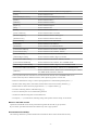
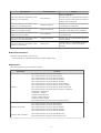
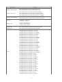
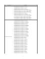
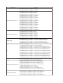
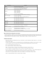
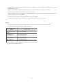


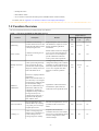
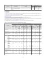
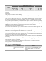
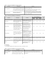

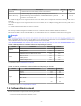
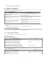
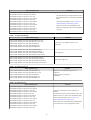
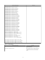
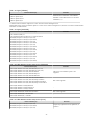
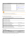
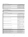
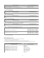
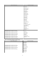
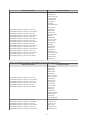
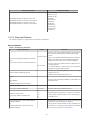
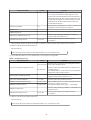
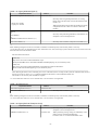
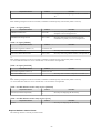
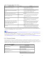
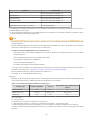
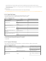
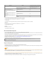
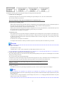

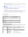
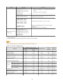
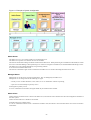

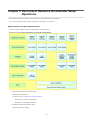


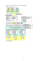
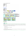

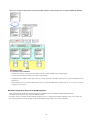
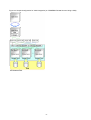
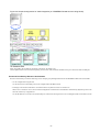
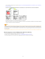
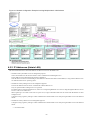


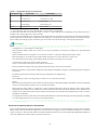
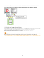
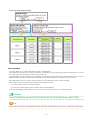

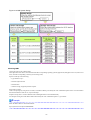


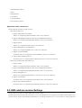


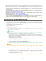
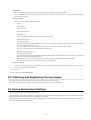

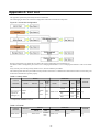
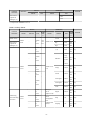
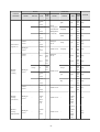
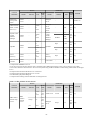
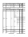
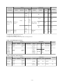
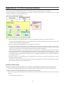

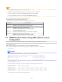


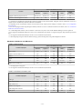
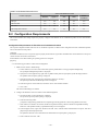


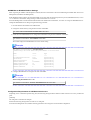


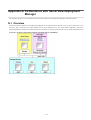
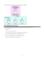


![Hire And Sales Catalogue V4.40 [april2013].](http://vs1.manualzilla.com/store/data/005975062_1-8950e43f7cbe305f577dc550ee5fbd1b-150x150.png)