1
Agilent 34410A/11A
6 ½ Digit Multimeter
(includes the L4411A 1U DMM)
Service Guide
Agilent Technologies
Notices
© Agilent Technologies, Inc. 2005 - 2007
Warranty
No part of this manual may be reproduced in
any form or by any means (including electronic storage and retrieval or translation
into a foreign language) without prior agreement and written consent from Agilent
Technologies, Inc. as governed by United
States and international copyright laws.
The material contained in this document is provided “as is,” and is subject to being changed, without notice,
in future editions. Further, to the maximum extent permitted by applicable
law, Agilent disclaims all warranties,
either express or implied, with regard
to this manual and any information
contained herein, including but not
limited to the implied warranties of
merchantability and fitness for a particular purpose. Agilent shall not be
liable for errors or for incidental or
consequential damages in connection with the furnishing, use, or performance of this document or of any
information contained herein. Should
Agilent and the user have a separate
written agreement with warranty
terms covering the material in this
document that conflict with these
terms, the warranty terms in the separate agreement shall control.
Manual Part Number
34410-90010
Edition
Fourth Edition. February 2007
Printed in Malaysia
Agilent Technologies, Inc.
3501 Stevens Creek Blvd.
Santa Clara, CA 95052 USA
Microsoft® and Windows® are U.S. registered trademarks of Microsoft Corporation.
Software Revision
This guide is valid for the firmware that was
installed in the instrument at the time of
manufacture. However, upgrading the firmware may add or change product features.
For the latest firmware and documentation,
go to the product page at:
Technology Licenses
www.agilent.com/find/34410A
Restricted Rights Legend
or
www.agilent.com/find/34411A
or
www.agilent.com/find/L4411A
2
The hardware and/or software described in
this document are furnished under a license
and may be used or copied only in accordance with the terms of such license.
U.S. Government Restricted Rights. Software and technical data rights granted to
the federal government include only those
rights customarily provided to end user customers. Agilent provides this customary
commercial license in Software and technical data pursuant to FAR 12.211 (Technical
Data) and 12.212 (Computer Software) and,
for the Department of Defense, DFARS
252.227-7015 (Technical Data - Commercial
Items) and DFARS 227.7202-3 (Rights in
Commercial Computer Software or Computer Software Documentation).
Safety Notices
CAUTION
A CAUTION notice denotes a hazard. It calls attention to an operating procedure, practice, or the like
that, if not correctly performed or
adhered to, could result in damage
to the product or loss of important
data. Do not proceed beyond a
CAUTION notice until the indicated
conditions are fully understood and
met.
WA R N I N G
A WARNING notice denotes a
hazard. It calls attention to an
operating procedure, practice, or
the like that, if not correctly performed or adhered to, could result
in personal injury or death. Do not
proceed beyond a WARNING
notice until the indicated conditions are fully understood and
met.
34410A/11A/L4411A Service Guide
Safety Information
Do not defeat power cord safety ground feature. Plug in to a grounded (earthed) outlet.
Do not use product in any manner not specified by the manufacturer.
Do not install substitute parts or perform
any unauthorized modification to the product. Return the product to an Agilent Technologies Sales and Service Office for service
and repair to ensure that safety features are
maintained.
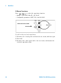
Safety Symbols
WA R N I N G
Main Power and Test Input Disconnect: Unplug instrument from
wall outlet, remove power cord,
and remove all probes from all
terminals before servicing. Only
qualified, service-trained personnel should remove the cover from
the instrument.
Earth Ground
WA R N I N G
Chassis Ground
Risk of electric shock
Line and Current Protection
Fuses: For continued protection
against fire, replace the line fuse
and the current-protection fuse
only with fuses of the specified
type and rating.
WA R N I N G
Refer to manual for additional safety information
CAT II (300V) IEC Measurement Category II.
Inputs may be connected to
mains (up to 300 VAC) under
Category II overvoltage conditions.
34410A/11A/L4411A Service Guide
WA R N I N G
IEC Measurement Category II. The
HI and LO input terminals may be
connected to mains in IEC Category II installations for line voltages up to 300 VAC. To avoid the
danger of electric shock, do not
connect the inputs to mains for
line voltages above 300 VAC. See
"IEC Measurement Category II
Overvoltage Protection" on the
following page for further information.
WA R N I N G
Protection Limits: To avoid instrument damage and the risk of electric shock, do not exceed any of
the Protection Limits defined in
the following section.
Front/Rear Switch: Do not
change the position of the
Front/Rear switch on the front
panel while signals are present on
either the front or rear set of terminals. The switch is not intended
as an active multiplexer. Switching while high voltages or currents are present may cause
instrument damage and lead to
the risk of electric shock.
3
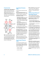
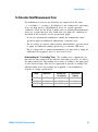
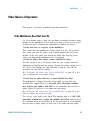
Protection Limits
The Agilent 34410A/11A Digital Multimeter
provides protection circuitry to prevent
damage to the instrument and to protect
against the danger of electric shock, provided the Protection Limits are not
exceeded. To ensure safe operation of the
instrument, do not exceed the Protection
Limits shown on the front and rear panel,
and defined below:
Input Terminal Protection
Limits
Protection Limits are defined for the input
terminals:
Main Input (HI and LO) Terminals. The HI
and LO input terminals are used for voltage,
resistance, capacitance, and diode test
measurements. Two Protection Limits are
defined for these terminals:
HI to LO Protection Limit. The Protection
Limit from HI to LO ("A" in the figure at
left) is 1000 VDC or 750 VAC, which is
also the maximum voltage measurement.
This limit can also be expressed as 1000
Vpk maximum.
LO to Ground Protection Limit. The LO
input terminal can safely "float" a maximum of 500 Vpk relative to ground. This is
Protection Limit "B" in the figure.
As is implied by the above limits, the Protection Limit for the HI input terminal is a maximum of 1500 Vpk relative to ground.
Note: The front-panel terminals are shown
above. The rear-panel terminals are identical. The Front/Rear switch selects the terminal set to be used. Do not operate this
switch while signals are present on the
front or rear terminals. The current-protection fuse is on the rear panel.
Current Input Terminal. The current input
("I") terminal has a Protection Limit of 3A
(rms) maximum current flowing from the LO
input terminal. This is Protection Limit "C"
in the figure. Note that the current input terminal will be at approximately the same
voltage as the LO terminal.
Note: The current-protection circuitry
includes a fuse on the rear panel. To maintain protection, replace this fuse only with a
fuse of the specified type and rating.
Sense Terminal Protection
Limits
The HI and LO sense terminals are used
only for four-wire resistance and temperature measurements ("Ω 4W"). The Protection Limit is 200 Vpk for all of the terminal
pairings ("D" in the figure):
LO sense to LO input.
HI sense to LO input.
Note: The 200 Vpk limit on the sense terminals is the Protection Limit. Operational
voltages in resistance measurements are
much lower — less than 10 V in normal
operation.
IEC Measurement Category II
Overvoltage Protection
To protect against the danger of electric
shock, the Agilent 34410A/11A Digital Multimeter provides overvoltage protection for
line-voltage mains connections meeting
both of the following conditions:
The HI and LO input terminals are connected to the mains under Measurement
Category II conditions, defined below, and
The mains are limited to a maximum line
voltage of 300 VAC.
IEC Measurement Category II includes electrical devices connected to mains at an outlet on a branch circuit. Such devices include
most small appliances, test equipment, and
other devices that plug into a branch outlet
or socket. The 34410A/11A may be used to
make measurements with the HI and LO
inputs connected to mains in such devices,
or to the branch outlet itself (up to 300
VAC). However, the 34410A/11A may not be
used with its HI and LO inputs connected to
mains in permanently installed electrical
devices such as the main circuit-breaker
panel, sub-panel disconnect boxes, or permanently wired motors. Such devices and
circuits are subject to overvoltages that may
exceed the protection limits of the
34410A/11A.
Note: Voltages above 300 VAC may be measured only in circuits that are isolated from
mains. However, transient overvoltages are
also present on circuits that are isolated
from mains. The Agilent 34410A/11A is
designed to safely withstand occasional
transient overvoltages up to 2500 Vpk. Do
not use this equipment to measure circuits
where transient overvoltages could exceed
this level.
HI sense to LO sense.
4
34410A/11A/L4411A Service Guide
Additional Notices
Waste Electrical and
Electronic Equipment (WEEE)
Directive 2002/96/EC
This product complies with the WEEE Directive (2002/96/EC) marking requirement.
The affixed product label (see below) indicates that you must not discard this electrical/electronic product in domestic
household waste.
Product Category: With reference to the
equipment types in the WEEE directive
Annex 1, this product is classified as a
"Monitoring and Control instrumentation"
product.
Do not dispose in domestic household
waste.
To return unwanted products, contact your
local Agilent office, or see
www.agilent.com/environment/product
for more information.
Agilent 34138A Test Lead Set
The Agilent 34410A/11A is provided with
an Agilent 34138A Test Lead Set, described
below.
Test Lead Ratings
Test Leads - 1000V, 15A
Fine Tip Probe Attachments - 300V, 3A
Mini Grabber Attachment - 300V, 3A
SMT Grabber Attachments - 300V, 3A
Operation
The Fine Tip, Mini Grabber, and SMT Grabber attachments plug onto the probe end of
the Test Leads.
Maintenance
If any portion of the Test Lead Set is worn or
damaged, do not use. Replace with a new
Agilent 34138A Test Lead Set.
WA R N I N G
If the Test Lead Set is used in a
manner not specified by Agilent
Technologies, the protection provided by the Test Lead Set may be
impaired. Also, do not use a damaged or worn Test Lead Set.
Instrument damage or personal
injury may result.
34410A/11A/L4411A Service Guide
5
DECLARATION OF CONFORMITY
According to EN ISO/IEC 17050-1:2004
Manufacturer’s Name:
Manufacturer’s Address:
Agilent Technologies, Incorporated
900 South Taft Ave
Loveland, CO 80537
USA
Declares under sole responsibility that the product as originally delivered
Product Name:
Model Number:
Product Options:
6 ½ Digit Multimeter
34410A, 34411A, L4411A
This declaration covers all options of the above product(s)
complies with the essential requirements of the following applicable European Directives, and
carries the CE marking accordingly:
Low Voltage Directive (73/23/EEC, amended by 93/68/EEC)
EMC Directive (89/336/EEC, amended by 93/68/EEC)
and conforms with the following product standards:
EMC
Standard
Limit
IEC 61326:2002 / EN 61326:1997+A1:1998 +A2:2000+A3:2003
Reference Standards
CISPR 11:1990 / EN 55011:1990
IEC 61000-4-2:1995 / EN 61000-4-2:1995
IEC 61000-4-3:1995 / EN 61000-4-3/1995
IEC 61000-4-4:1995 / EN 61000-4-4:1995
IEC 61000-4-5:1995 / EN 61000-4-5:1995
IEC 61000-4-6:1996 / EN 61000-4-6:1996
IEC 61000-4-11:1994 / EN 61000-4-11:1994
Class A Group 1
4 kV/4 kV contact/air
3 V/m, 80-1000 MHz
0.5 kV signal lines, 1 kV power lines
0.5 kV line-line, 1 kV line-ground
3 V, 0.15-80 MHz
1 cycle, >95%
Canada: ICES-001:2004
Australia/New Zealand: AS/NZS CISPR 11:2002
The product was tested in a typical configuration with Agilent Technologies test systems.
IEC 61010-1:2001 / EN 61010-1:2001
Safety
Canada: CAN/CSA-C22.2 No. 61010-1-04,
USA: ANSI/UL 61010-1:2005
168520
Supplementary Information:
This DoC applies to above-listed products placed on the EU market after:
17 January 2007
Date
David L. Kepler
Quality Manager
For further information, please contact your local Agilent Technologies sales office, agent or distributor,
or Agilent Technologies Deutschland GmbH, Herrenberger Straße 130, D 71034 Böblingen, Germany.
6
34410A/11A/L4411A Service Guide
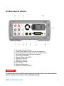
Agilent 34410A/11A/L4411A at a Glance
The Agilent 34410A, 34411A, or L4411A multimeter provides
6½- digit, high- performance dc and ac measurements.
• Voltage and Current Measurements. DC and AC(true- rms).
• Resistance Measurements. 2- wire and 4- wire.
• Continuity and Diode Testing.
• Frequency and Period Measurements.
• Capacitance Measurements.
• Temperature Measurements. Thermistor and RTD.
• Auto and Manual Ranging.
• Math Features. Null, dB, dBm, limits, and statistics.
• Data Logging. Into non- volatile instrument memory.
• Instrument State Storage. User- defined named states.
• GPIB (IEEE- 488), USB, and LAN. Three standard
remote interfaces. LXI Class C Compliant.
• Web Interface. Direct web browser access to instrument.
• SCPI Compatibility. For easy instrument programming.
• Voltmeter Complete and External Trigger Signals.
Synchronize with other instruments in your test system.
Note: This manual covers the operation of the Agilent
34410A, 34411A, and L4411A 6½ Digit Multimeters. The
features described in this manual, except where otherwise
noted, apply to the 34410A, 34411A, and L4411A.
Key Differences:
Model 34410A
• Up to 10,000 readings per second.
• Reading memory (buffer) up
to 50,000 readings.
34410A/11A/L4411A Service Guide
Model 34411A/L4411A
• Up to 50,000 readings per second.
• Reading memory (buffer) up
to 1 million readings.
• Pretriggering, internal level triggering,
and digitizer specifications.
7
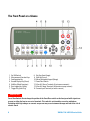
The Front Panel at a Glance
1
2
3
4
5
6
7
On/Off Switch
Measurement Function Keys
Configuration Key
Second Display Key (Reset)
Null Key (Math Functions)
Data Logger Key (Utility)
Trigger Key (Auto Trig)
8
9
10
11
12
13
14
Exit Key (Auto Range)
Shift Key (Local)
Menu Navigation Keypad (Range)
Front/Rear Switch
HI and LO Sense Terminals (4-wire measurements)
HI and LO Input Terminals (all functions except current)
Current Input Terminal (ac and dc current)
WA R N I N G
Front/Rear Switch: Do not change the position of the Front/Rear switch on the front panel while signals are
present on either the front or rear set of terminals. This switch is not intended as an active multiplexer.
Switching while high voltages or currents are present may cause instrument damage and lead to the risk of
electric shock.
8
34410A/11A/L4411A Service Guide
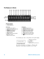
The Rear Panel at a Glance
1
2
3
4
5
6
7
8
9
10
11
12
Current Input Fuse (front and rear)
HI and LO Sense Terminals (4-wire resistance and temperature)
HI and LO Input Terminals (voltage, resistance, and other functions)
Current Input Terminal (ac current and dc current only)
External Trigger Input (BNC)
Voltmeter Complete Output (BNC)
LAN Interface Connector
USB Interface Connector
GPIB Interface Connector
Chassis Ground
Power-Line Voltage Setting
Power-Line Fuse-Holder Assembly
WA R N I N G
For protection from electrical shock, the power cord ground must not be defeated. For continued protection
from fire, replace fuses only with fuses of the specified type and rating.
34410A/11A/L4411A Service Guide
9
The Display at a Glance
Alphanumeric Displays:
1 Primary display line
2 Secondary display line
Annunciators:
3 * (measurement in progress)
4 Hi-Z (high input impedance, Vdc only)
5 OComp (offset compensation)
6 ManRng (manual ranging)
7 Trig (wait-for-trigger state)
8 Hold (reading hold)
9 Remote (remote interface operation)
10 Error (error in queue)
11 Null (null function enabled)
Annunciators:
12 Shift (shift key just pressed)
13 Math (dB or dBm function enabled)
14 Stats (statistics functions enabled)
15 Limits (limit-test function enabled)
16 Rear (rear-panel terminals active)
17 4W (four-wire ohms or temperature)
18
(continuity test function enabled)
19
(diode-check function enabled)
The following key refers to the primary front- panel display.
For further information, see Chapter 2, “Features and
Functions” in the Agilent 34410A/11A User’s Guide.
10
34410A/11A/L4411A Service Guide
The L4411A at a Glance
1
L4411A Option 1 - Front Panel Measurement Terminals
2
2
4
3
1
2
3
4
5
6
7
8
9
5
6
7
8
9
On/Stand-By button
Input measurement terminals - rear panel or front panel (optional)
Input current protection fuse (Agilent p/n 2110-0780)
External trigger input - BNC
Voltmeter (measurement) complete output - BNC
GPIB interface connector
LAN Reset - resets the L4411A LAN configuration to its factory default settings
LAN Interface connector - non Auto-MDIX; may require crossover cable (included)
High-Speed USB interface connector (type B)
34410A/11A/L4411A Service Guide
11
In This Guide…
1
Specifications
This chapter lists the multimeter’s specifications and
describes how to interpret these specifications.
2
Quick Start
This chapter prepares the multimeter for use and helps you
get familiar with a few of the front panel features.
3
Calibration
This chapter provides calibration, verification, and
adjustment procedures for the multimeter.
4
Disassembly and Repair
This chapter provides guidelines for returning the multimeter
to Agilent Technologies for servicing, or for servicing it
yourself. The chapter includes disassembly instructions and
a list of replaceable parts.
5
Backdating
This chapter describes the differences between this guide
and older versions of this guide.
12
34410A/11A/L4411A Service Guide
Contents
1
Specifications
17
DC Characteristics 19
AC Characteristics 22
Frequency and Period Characteristics 24
Capacitance Characteristics 26
Temperature Characteristics 26
Additional 34411A/L4411A Specifications 27
Measurement and System Speeds 28
System Speeds 29
Data From Memory 30
General Specifications 30
Dimensions 32
To Calculate Total Measurement Error 33
Interpreting Accuracy Specifications 35
Transfer Accuracy 35
24–Hour Accuracy 35
90–Day and 1–Year Accuracy 35
Temperature Coefficients 35
Configuring for Highest Accuracy Measurements 36
DC Voltage, DC Current, and Resistance Measurements: 36
AC Voltage and AC Current Measurements: 36
Frequency and Period Measurements: 36
34410A/11A/L4411A Service Guide
13
Contents
2
Quick Start
37
Basic Multimeter Operations 38
Preparing the Multimeter for Use 38
Using the Front Panel 39
Front-Panel Keys 39
Front-Panel Display Shortcuts 40
Making Basic Measurements 41
To Measure DC Voltage 42
To Measure AC Voltage 42
To Measure DC Current 43
To Measure AC Current 43
To Make a 2-Wire Resistance Measurement 44
To Make a 4-wire Resistance Measurement 44
To Measure Frequency 45
To Measure Period 45
To Measure Capacitance 46
To Make a 2-Wire Temperature Measurement 47
To Make a 4-Wire Temperature Measurement 47
To Test Continuity 48
To Check Diodes 48
Other Basics of Operation 49
If the Multimeter Does Not Turn On 49
To Replace the Power-Line Fuse (34410A/11A) 50
To Adjust the Carrying Handle (34410A/11A) 51
To Rack Mount the 34410A/11A Multimeter 51
To Rack Mount the L4411A Multimeter 52
Calibration Operation (34410A/11A) 53
To Read the Calibration Count 53
To Read the Calibration Message 54
To Store a Calibration Message 54
To Secure for Calibration 55
To Unsecure for Calibration 56
To Re-secure 56
14
34410A/11A/L4411A Service Guide
Contents
3
Calibration Procedures
57
Agilent Technologies Calibration Services 58
Calibration Interval 58
Adjustment is Recommended 58
Time Required for Calibration 59
Automating Calibration Procedures 59
Recommended Test Equipment 60
Performance Verification Tests 60
Self–Test 61
Quick Performance Check 61
Performance Verification Tests 62
Input Connections 62
Test Considerations 63
Verification Tests 64
Zero Offset Verification 64
Gain Verification 66
Optional AC Voltage Performance Verification Tests 72
Optional AC Current Performance Verification Tests 73
Optional Capacitance Performance Verification Tests 74
Calibration Security 75
To Unsecure the Instrument Without the Security Code 75
Calibration Message 77
Calibration Count 77
Calibration Process 78
Using the Front Panel for Adjustments (34410A/11A Only) 78
Selecting the Adjustment Mode 78
Entering Adjustment Values 78
Storing the Calibration Constants 78
Using the Remote Interface for Adjustments 79
Selecting the Adjustment Mode 79
Entering Adjustment Values 79
Storing the Calibration Constants 79
Aborting a Calibration in Progress 79
Adjustments 80
ADC and Zero Adjustment 80
Gain Adjustments 82
Flatness Adjustments 93
Finishing Adjustments 102
34410A/11A/L4411A Service Guide
15
Contents
4
Disassembly and Repair
103
Operating Checklist 104
Types of Service Available 105
Extended Service Contracts 105
Obtaining Repair Service (Worldwide) 105
Repackaging for Shipment 106
Cleaning 106
To Replace the 34410A/11A Power Line Fuse 106
To Replace the Current Input Fuse 107
Self Test Procedures 107
Power–On Self–Test 107
34410A/11A Complete Self–Test 107
L4411A Complete Self–Test 107
Self Test Error Numbers 108
Calibration Errors 109
34410A/11A Display and Keypad Tests 110
Electrostatic Discharge (ESD) Precautions 110
34410A/11A Mechanical Disassembly 111
General Disassembly 111
Front Panel Removal 113
Front Panel Disassembly 116
L4411A Mechanical Disassembly 117
General Disassembly 117
Replaceable Parts 122
To Order Replaceable Parts 122
Parts List 34410A/11A 123
Parts List L4411A 124
5
16
Backdating
125
34410A/11A/L4411A Service Guide
Agilent 34410A/11A/L4411A 6½ Digit Multimeter
Service Guide
1
Specifications
DC Characteristics 19
AC Characteristics 22
Frequency and Period Characteristics 24
Capacitance Characteristics 26
Temperature Characteristics 26
Additional 34411A/L4411A Specifications 27
Measurement and System Speeds 28
General Specifications (34410A/11A) 30
Dimensions 32
To Calculate Total Measurement Error 33
Interpreting Accuracy Specifications 35
Configuring for Highest Accuracy Measurements 36
Agilent Technologies
17
1
Specifications
These specifications apply when using the 34410A/11A/L4411A multimeter
in an environment that is free of electromagnetic interference and
electrostatic charge.
When using the multimeter in an environment where electromagnetic
interference or significant electrostatic charge is present, measurement
accuracy may be reduced. Particularly note:
• The voltage measurement probes are not shielded and can act as
antennas, causing electromagnetic interference to be added to the signal
being measured.
• Electrostatic discharges of 4000 V or greater may cause the multimeter
to temporarily stop responding, resulting in a lost or erroneous reading.
NOTE
The specifications on the following pages are valid for Agilent 34410A, 34411A, or L4411A
multimeters with firmware revision 2.05, or later, installed.
Specifications are subject to change without notice. For the latest
specifications, see the product datasheet on the Web. Firmware updates
may also be available on the Web. Start at the appropriate product page:
www.agilent.com/find/34410A
www.agilent.com/find/34411A
www.agilent.com/find/L4411A
18
34410A/11A/L4411A Service Guide
Specifications
1
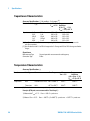
DC Characteristics
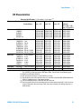
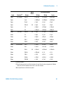
Accuracy Specifications ( % of reading + % of range ) [1]
Function
Range [3]
DC
100.0000 mV
1.000000 V
10.00000 V
100.0000 V
1000.000 V [5]
Test Current or
Burden Voltage
24 Hour [2]
TCAL ± 1 °C
90 Day
TCAL ± 5 °C
1 Year
TCAL ± 5 °C
Temperature
Coefficient
0 °C to (TCAL – 5 °C)
(TCAL + 5 °C) to 55 °C
0.0030+0.0030
0.0020+0.0006
0.0015+0.0004
0.0020+0.0006
0.0020+0.0006
0.0040+0.0035
0.0030+0.0007
0.0020+0.0005
0.0035+0.0006
0.0035+0.0006
0.0050+0.0035
0.0035+0.0007
0.0030+0.0005
0.0040+0.0006
0.0040+0.0006
0.0005+0.0005
0.0005+0.0001
0.0005+0.0001
0.0005+0.0001
0.0005+0.0001
Resistance [4] 100.0000 Ω
1.000000 KΩ
10.00000 KΩ
100.0000 KΩ
1.000000 MΩ
10.00000 MΩ
100.0000 MΩ
1000.000 MΩ
1 mA Current Source
1 mA
100 µA
10 µA
5.0 µA
500 nA
500 nA || 10 MΩ
500 nA || 10 MΩ
0.0030+0.0030
0.0020+0.0005
0.0020+0.0005
0.0020+0.0005
0.0020+0.0010
0.0100+0.0010
0.200+0.001
2.000+0.001
0.008+0.004
0.007+0.001
0.007+0.001
0.007+0.001
0.010+0.001
0.030+0.001
0.600+0.001
6.000+0.001
0.010+0.004
0.010+0.001
0.010+0.001
0.010+0.001
0.012+0.001
0.040+0.001
0.800+0.001
8.000+0.001
0.0006+0.0005
0.0006+0.0001
0.0006+0.0001
0.0006+0.0001
0.0010+0.0002
0.0030+0.0004
0.1000+0.0001
1.0000+0.0001
DC Current
100.0000 µA
1.000000 mA
10.00000 mA
100.0000 mA
1.000000 A
3.00000 A
<0.03 V Burden V
<0.3 V
<0.03 V
<0.3 V
<0.80 V
<2.0 V
0.010+0.020
0.007+0.006
0.007+0.020
0.010+0.004
0.050+0.006
0.100+0.020
0.040+0.025
0.030+0.006
0.030+0.020
0.030+0.005
0.080+0.010
0.120+0.020
0.050+0.025
0.050+0.006
0.050+0.020
0.050+0.005
0.100+0.010
0.150+0.020
0.0020+0.0030
0.0020+0.0005
0.0020+0.0020
0.0020+0.0005
0.0050+0.0010
0.0050+0.0020
Continunity
1000 Ohms
1 mA Test Current
0.002+0.010
0.008+0.020
0.010+0.020
0.0010+0.0020
Diode Test
[6]
1 mA Test Current
0.002+0.010
0.008+0.020
0.010+0.020
0.0010+0.0020
1.0000 V
[ 1 ] Specifications are for 90 minute warm–up and integration setting of 100 NPLC.
For <100 NPLC, add the appropriate “RMS Noise Adder” from the table on the following page.
[ 2 ] Relative to calibration standards.
[ 3 ] 20% overrange on all ranges, except 1000 Vdc, 3 A range.
[ 4 ] Specifications are for 4–wire ohms function, or 2–wire ohms using Math Null. Without Math Null,
add 0.2 Ω additional error in 2–wire ohms function.
[ 5 ] For each additional volt over ± 500 VDC add 0.02 mV of error.
[ 6 ] Accuracy specifications are for the voltage measured at the input terminals only. 1 mA test current
is typical. Variation in the current source will create some variation in the voltage drop across a
diode junction.
34410A/11A/L4411A Service Guide
19
1
Specifications
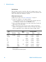
Performance Versus Integration Time – 60Hz (50Hz) Power line frequency
RMS Noise Adder % range [4]
Integration Time
Number of Power
Line Cycles (NPLC)
0.001 [6]
0.002 [6]
0.006
0.02
0.06
0.2
1
2
10
100
Resolution
ppm Range [1]
NMR db [2]
Readings /
Second [3]
DCV
10, 1000 V
DCV
1, 100 V
Resistance
1K, 10K ohm
DCV
0.1 V
Resistance
100 ohm
DCI
1 amp
50,000
30
0.0060
0
0.0100
0.1000
25,000
15
0.0030
0
0.0060
0.0600
10,000
6
0.0012
0
0.0040
0.0600
3000
3
0.0006
0
0.0030
0.0300
1000
1.5
0.0003
0
0.0020
0.0200
300
0.7
0.0002
0
0.0015
0.0150
60(50)
0.3
0.0
55
0.0001
0.0010
30(25)
0.2
0.0
110 [5]
0.0001
0.0010
110 [5]
6(5)
0.1
0.0
0.0
0.0005
110 [5]
0.6(0.5)
0.03
0.0
0.0
0.0
[ 1 ] Resolution is defined as the typical 10 VDC range RMS noise.
[ 2 ] Normal mode rejection for power–line frequency ± 0.1%.
[ 3 ] Maximum rate for DCV, DCI, and 2–Wire resistance functions
(using zero settling delay, autozero off, etc.).
[ 4 ] Autozero on for => 1 NPLC.
Basic dc accuracy specifications (previous page) include RMS noise at 100 NPLC.
For <100 NPLC, add appropriate “RMS Noise Adder” to basic accuracy specification.
[ 5 ] For power–line frequency ± 1% 75 dB and for ± 3% 55 dB.
[ 6 ] Only for 34411A /L4411A.
Transfer Accuracy (Typical)
All DC volts, <0.12 A DC Current, < 1.2 MΩ: (24 hour % of range error) / 2)
All other DC current and resistance: (24 hour % of range error + % of reading)/2
Conditions:
- Within 10 minutes and ±0.5 °C
- Within ±10% of initial value.
- Following a 2–hour warm–up.
- Fixed range.
- Using >= 10 NPLC.
- Measurements are made using accepted metrology practices.
20
34410A/11A/L4411A Service Guide
Specifications
1
DC Voltage
Measurement Method:
10 VDC Linearity:
Input Resistance:
0.1 V, 1 V, 10 V Ranges
100 V, 1000 V Ranges
Input Bias Current:
Input Terminals:
Input Protection:
DC CMRR
Continuously integrating multi–slope IV
0.0002% of reading + 0.0001% of range
Selectable 10 MΩ or >10 GΩ
(For these ranges, inputs beyond ±17 V are clamped
through 100 kΩ typical)
10 MΩ ±1%
< 50 pA at 25 °C
Copper alloy
1000 V
140 dB for 1 kΩ unbalance in LO lead. ±500 VDC maximum
Resistance
Measurement Method:
Max. Lead Resistance
(4–wire ohms)
Input Protection:
Offset Compensation:
Selectable 4–wire or 2–wire ohms.
10% of range per lead for 100 Ω, 1 kΩ ranges.
1 kΩ per lead on all other ranges
1000 V on all ranges
Selectable on the 100 Ω, 1 kΩ, and 10 kΩ ranges
DC Current
Shunt Resistor:
Input Protection:
0.1Ω for 1 A, 3 A.
2 Ω for 10 mA, 100 mA.
200 Ω for 100 µA, 1 mA.
Externally accessible 3 A, 250 V fuse
Continuity / Diode Test
Response Time:
Continuity Threshold:
300 samples / sec with audible tone
Fixed at 10 Ω
Autozero OFF Operation (Typical)
Following instrument warm–up at a stable ambient temperature ±1 °C and <5 minutes.
Add 0.0002% of range + 2 µV for DCV or + 2 mΩ for resistance.
Settling Considerations
Reading settling times are affected by source impedance, cable dielectric characteristics, and input
signal changes. Default delays are selected to give first reading right for most measurements.
Measurement Considerations
Agilent recommends the use of Teflon or other high–impedance, low–dielectric absorption wire
insulation for these measurements.
34410A/11A/L4411A Service Guide
21
1
Specifications
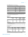
AC Characteristics
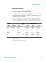
Accuracy Specifications ( % of reading + % of range ) [1]
Function
Range [3]
Frequency Range 24 Hour [2]
TCAL ± 1 °C
90 Day
TCAL ± 5 °C
1 Year
TCAL ± 5 °C
Temperature
Coefficient
0 °C to (TCAL – 5 °C)
(TCAL + 5 °C) to 55 °C
0.50 + 0.03
0.10 + 0.03
0.05 + 0.03
0.09 + 0.05
0.30 + 0.08
1.20 + 0.50
0.50 + 0.03
0.10 + 0.03
0.06 + 0.03
0.10 + 0.05
0.40 + 0.08
1.20 + 0.50
0.010 + 0.003
0.008 + 0.003
0.005 + 0.003
0.010 + 0.005
0.020 + 0.008
0.120 + 0.020
True RMS AC
Voltage [4]
100.0000 mV 3 Hz – 5 Hz
to
5 Hz – 10 Hz
750.000 V
10 Hz – 20 kHz
20 kHz – 50 kHz
50 kHz – 100 kHz
100 kHz – 300 kHz
True RMS AC
Current [5]
100.0000µA 3 Hz – 5 kHz
0.10 + 0.04
0.10 + 0.04
0.10 + 0.04
0.015 + 0.006
to 3.00000A 5 kHz – 10 kHz
0.20 + 0.04
0.20 + 0.04
0.20 + 0.04
0.030 + 0.006
[ 1 ] Specifications are for 90 minute warm–up, slow ac filter, sinewave.
[ 2 ] Relative to calibration standards.
[ 3 ] 20% overrange on all ranges, except 750 Vac, 3 A range.
[ 4 ] Specifications are for sinewave input >0.3% of range and > 1mVrms.
Add 30 µV error to AC voltage specification for frequencies < 1kHz.
750 VAC range limited to 8 x 10⁷ Volt–Hz.
750 VAC range add 0.7 mV of error for each additional volt over 300 VAC.
[ 5 ] Specifications are for sinewave input >1% of range and > 10 µArms.
Specifications for the 100 µA, 1 mA, 1 A and 3 A ranges are typical for frequencies above 5 kHz.
For the 3 A range (all frequencies) add 0.05% of reading + 0.02% of range to listed specifications.
0.50 + 0.02
0.10 + 0.02
0.02 + 0.02
0.05 + 0.04
0.20 + 0.08
1.00 + 0.50
Low Frequency Performance
Three filter settings are available: 3 Hz, 20 Hz, 200Hz.
Frequencies greater than these filter settings are specified with no additional errors.
AC Current Burden Voltage
22
ACI Ranges
Voltage
100.0000 µA
1.000000 mA
10.00000 mA
100.0000 mA
1.000000 A
3.00000 A
<0.03 V
<0.3 V
<0.03 V
<0.3 V
<0.8 V
<2.0 V
34410A/11A/L4411A Service Guide
Specifications
1
Voltage Transfer Accuracy ( typical )
Frequency
10 Hz to 300 kHz
Conditions:
Error
(24 hour % of range + % of reading)/5
- Sinewave input only using slow filter.
- Within 10 minutes and ±0.5 °C.
- Within ±10% of initial voltage and ±1% of initial frequency.
- Following a 2–hour warm–up.
- Fixed range between 10% and 100% of full scale (and <120 V).
- Measurements are made using accepted metrology practices
True RMS AC Voltage
Measurement Type
AC–coupled True RMS. Measures the AC component of the input.
Measurement Method:
Digital sampling with anti–alias filter.
AC Common Mode Rejection
70 dB For 1 kΩ unbalanced in LO lead and <60 Hz. ±500 V peak maximum.
Maximum Input:
400 Vdc, 1100 Vpeak
Input Impedance:
1 MΩ ± 2%, in parallel with <150 pF
Input Protection:
750 V rms all ranges
True RMS AC Current
Measurement Type:
Measurement Method:
Maximum Input:
Shunt Resistor:
Input Protection:
Directly coupled to the fuse and shunt.
AC–coupled True RMS measurement (measure the AC component only).
Digital sampling with anti–alias filter.
The peak value of the DC + AC current must be <300% of range.
The RMS current <3 A including the DC current content.
0.1 Ω for 1A, 3A,
2 Ω for 10 mA 100 mA,
200 Ω for 100 µA, 1 mA
Externally accessible 3A, 250 V fuse
Crest Factor and Peak Input
Crest Factor:
Peak Input:
Overload Ranging
For <10:1 errors included.
Limited by peak input and 300 kHz bandwidth.
300% of Range. Limited by maximum input
Will select higher range if peak input overload is detected during
auto range. Overload is reported in manual ranging.
Settling Considerations
Default delays are selected to give first reading right for most measurements. The input blocking RC
time constant must be allowed to fully settle before the most accurate measurements are possible
34410A/11A/L4411A Service Guide
23
1
Specifications
Frequency and Period Characteristics
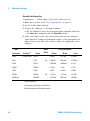
Accuracy Specifications ( % of reading ) [ 1, 3 ]
Function
Range
Frequency Range
24 Hour [2]
TCALC ± 1 °C
90 Day
TCAL ± 5 °C
1 Year
TCAL ± 5 °C
Temperature
Coefficient
0 °C to (TCAL – 5 °C)
(TCAL + 5 °C) to 55 °C
Frequency
Period
100 mV
to
750 V
3 Hz – 5 Hz
5 Hz – 10 Hz
10 Hz – 40 Hz
40 Hz – 300 kHz
0.07
0.04
0.02
0.005
0.07
0.04
0.02
0.006
0.07
0.04
0.02
0.007
0.005
0.005
0.001
0.001
Additional Errors ( % of reading ) [3]
Aperture (resolution / range)
Frequency
1 Second
(0.1 ppm)
0.1 Second
(1 ppm)
0.01 Second
(10 ppm)
0.001 Second
(100 ppm)
3 Hz – 5 Hz
0
0.11
0.11
0.11
5 Hz – 10 Hz
0
0.14
0.14
0.14
10 Hz – 40 Hz
0
0.16
0.16
0.16
40 Hz – 300 kHz
0
0.045
0.17
0.17
[ 1 ] Specifications are for 90 minute warm–up, using 1 second aperture.
[ 2 ] Relative to calibration standards.
[ 3 ] For AC input voltages 10% to 120% of range except where noted. 750 V range limited to 750 Vrms.
100 mV range specifications are for full scale or greater inputs. For inputs from 10 mV to 100 mV,
multiply total % of reading error by 10.
Transfer Accuracy ( typical ) 0.0003% of reading
Conditions:
24
- Within 10 minutes and ± 0.5 °C.
- Within ±10% of initial voltage and ± 1% of initial frequency.
- Following a 2–hour warm–up.
- For inputs > 1 kHz and > 100 mV
- Using 1 second gate time
- Measurements are made using accepted metrology practices.
34410A/11A/L4411A Service Guide
Specifications
1
Frequency and Period
Measurement Type:
Input Impedance:
Input Protection:
Reciprocal–counting technique. AC–coupled input using the AC voltage
measurement function.
1 MΩ ±2%, in parallel with <150 pF
750 V rms all ranges
Measurement Considerations
All frequency counters are susceptible to error when measuring low–voltage, low–frequency signals.
Shielding inputs from external noise pickup is critical for minimizing measurement errors.
Settling Considerations
Errors will occur when attempting to measure the frequency or period of an input following a dc offset
voltage change. The input blocking RC time constant must be allowed to fully settle ( up to 1 sec. )
before the most accurate measurements are possible.
34410A/11A/L4411A Service Guide
25
1
Specifications
Capacitance Characteristics
Accuracy Specifications ( % of reading + % of range ) [1]
Function
Range [2]
Test Current
1 Year
TCAL ± 5 °C
Temperature
Coefficient
0 °C to (TCAL – 5 °C)
(TCAL + 5 °C) to 55 °C
Capacitance
1 nF
500 nA
0.50 + 0.50
0.05 + 0.05
10 nF
1 µA
0.40 + 0.10
0.05 + 0.01
100 nF
10 µA
0.40 + 0.10
0.01 + 0.01
1 µF
100 µA
0.40 + 0.10
0.01 + 0.01
10 µF
1 mA
0.40 + 0.10
0.01 + 0.01
[ 1 ] Specifications are for 90 minute warm–up using Math Null. Additional errors may occur for
non–film capacitors.
[ 2 ] Specifications are for 1% to 120% of range on the 1 nF range and 10% to 120% of range on all other
ranges.
Capacitance
Measurement Type:
Connection Type:
Current input with measurement of resulting ramp.
2 Wire
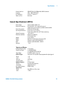
Temperature Characteristics
Accuracy Specifications [1]
Function
Probe Type
Ro
Best Range
1 Year
TCAL ± 5 °C
Temperature
Coefficient
0 °C to (TCAL – 5 °C)
(TCAL + 5 °C) to 55 °C
Temperature
RTD
from 49 W to 2.1 kW –200 oC to 600 oC
0.06 oC
0.003 oC
Thermistor
N/A
–80 oC to 150 oC
0.08 oC
[ 1 ] For total measurement accuracy, add temperature probe error
0.002 oC
Examples (RTD probe, measurement within “Best Range”):
1.) Meter within TCAL ± 5 °C: Error = 0.06 oC + probe error
2.) Meter at TCAL + 10 °C:
26
Error = 0.06 oC + (5 x 0.003 oC) + probe error = 0.075 oC + probe error
34410A/11A/L4411A Service Guide
Specifications
Function[1]
DCV
2-wire Ω
DCI
ACV
ACI
Frequency
Period
1
Digits
4.5
5.5
6.5
50k
50k
50k
500
500
450
450
10k
10k
10k
500
150
90
90
1k
1k
1k
150
150
10
10
Additional 34411A/L4411A Specifications
Resolution
Overall Bandwidth, DCV and DCI
Triggering
Timebase Resolution
Trigger Jitter
External Trigger Latency
Internal Trigger Level Accuracy
See table on page 20
15 kHz typical @ 20 µs aperture (–3 dB)
Pre or Post, Internal or External, Positive or Negative
19.9524 µs, 0.01% accuracy
2 µs(p-p), 20 µs(p-p) when pre-triggered
< 3 µs
1% of range
Spurious-Free Dynamic Range and SNDR
Function
Range
Spurious-Free
Dynamic Range
Signal to Noise
Distortion Ratio (SNDR)
DCV
100.0000 mV
1.000000 V
10.00000 V [1]
100.0000 V
1000.000 V
–55 dB
–75 dB
–70 dB
–75 dB
–60 dB
40 dB
60 dB
65 dB
60 dB
55 dB
DCI
100.0000 µA [2]
1.000000 mA
10.00000 mA
100.0000 mA
1.000000 A
3.00000 A
–50 dB
–65 dB
–45 dB
–65 dB
–65 dB
–70 dB
38 dB
50 dB
38 dB
50 dB
55 dB
55 dB
[1] 10 V range specifications are valid for signals 2 V(p-p) < x(t) < 16 V(p-p)
[2] 100 µA range specifications are valid for signals 28.8 µA(p-p) < x(t) < 200 µA(p-p)
34410A/11A/L4411A Service Guide
27
1
Specifications
Measurement and System Speeds
DMM Measurements Speeds
Direct I/O Measurements [1]
Single Reading – Measure and I/O Time
Function
Resolution
(NPLC)
DCV (10 V Range)
0.001 [2]
0.0026
0.0029
0.0046
0.0032
50000
0.006
0.0026
0.0029
0.0046
0.0032
10000
0.06
0.0031
0.0032
0.0047
0.0040
1000
1
0.0190
0.0190
0.0200
0.0190
60
ACV (10 V Range)
2–Wire Ω (10 kΩ Range)
4–wire Ω (10 kΩ Range)
Frequency
1 KHz, 10 V Range
Fast Filter
USB 2.0
Sec
Slow Filter
0.0100
0.0100
0.0100
0.0100
50
Medium Filter
0.0100
0.0100
0.0100
0.0100
150
Fast Filter
0.0100
0.0100
0.0100
0.0100
500
0.001 [2]
0.0026
0.0029
0.0046
0.0032
50000
0.006
0.0026
0.0029
0.0046
0.0032
10000
0.06
0.0031
0.0032
0.0047
0.0040
1000
1
0.0190
0.0190
0.0200
0.0190
60
0.001 [2]
0.0054
0.0040
0.0045
0.0056
1500
0.006
0.0054
0.0040
0.0045
0.0056
1200
0.06
0.0074
0.0078
0.0078
0.0074
380
1
0.0390
0.0390
0.0390
0.0390
30
1 ms Gate
0.0100
0.0100
0.0100
0.0100
500
10 mS Gate
0.0200
0.0200
0.0200
0.0200
80
100 mS Gate
0.1150
0.1150
0.1130
0.1130
10
1 S Gate
Capacitance (100 nF Rage)
GPIB
Sec
Measurement
Into Memory
LAN (VXI-11) LAN (Sockets) (Readings/Sec)
(VM Complete)
Sec
Sec
1.0200
1.0200
1.0200
1.0200
1
0.0820
0.0820
0.0820
0.0820
11
[1] Typical. Display off, ½ scale input signal, immediate trigger, trigger delay 0, autozero off,
autorange off, no math, 60 Hz line, null off, sample count 1, trig count 1, one interface enabled.
[2] 0.001 PLC applies to 34411A/L4411A only.
28
34410A/11A/L4411A Service Guide
Specifications
1
Direct I/O Measurements [1] (any remote interface)
Sustained maximum reading rate to I/O, 32–bit BINARY data ("SAMP:COUN 50000;:R?")
Function
Resolution (NPLC)
rdgs/Sec
DCV
0.001
0.006
50000 (34411A/L441A only)
10000
ACV
Fast Filter
500
2–Wire Ω
0.001
0.006
50000 (34411A/L4411A only)
10000
4–Wire Ω
0.001
0.006
1500 (34411A/L4411A only)
1200
Frequency/Period (1 k rdgs)
1 mS gate, fast filter
450
Capacitance (100 rdgs)
10
[1] ½ scale input signal, immediate trigger, trigger delay 0, autozero off, autorange off, no math,
60 Hz line, null off, sample count 50000, trigger count INF
System Speeds
General
Configuration [1]
(Sec)
Auto Range [2]
(Sec)
Maximum
External Trigger
Rate [3]
Maximum
Internal Trigger
Rate [3]
DCV
0.022
0.0075
5000 /S
10000 / S
ACV
0.037
0.019
500 / S
500 / S
2–Wire Ω
0.022
0.0075
5000 / S
10000 / S
Frequency/Period
0.037
0.019
500 / S
500 / S
[1] Time for configuration change from 2-wire ohms to listed function (or from dc volts to 2-wire ohms)
using appropriate FUNCtion command.
[2] Time to automatically change one range and be ready for new measurement, <=10V, <=10Mohm.
[3] Readings to memory.
Range Change
GPIB [1]
Sec
USB 2.0 [1]
Sec
LAN (VXI-11) [1]
Sec
LAN (Sockets) [1]
Sec
DCV
0.0026
0.0035
0.0039
0.0039
ACV
0.0064
0.0064
0.0096
0.0065
2–Wire Ω
0.0026
0.0038
0.0039
0.0039
Frequency/Period
0.0064
0.0064
0.0093
0.0065
[1] Time to change from one range to next higher or lower range, <=10V, <=10Mohm.
34410A/11A/L4411A Service Guide
29
1
Specifications
Data From Memory
Maximum reading rate out of memory
(Sample count 50000, trigger count 1, "FETC?" or "R?")
Readings
ASCII
GPIB
rdg/Sec
USB 2.0
rdg/Sec
LAN (VXI-11)
rgs/Sec
LAN (Sockets)
rdg/Sec
4000
8500
7000
8500
4–byte Binary
89,000
265,000
110,000
270,000
8–byte Binary
47,000
154,000
60,000
160,000
General Specifications (34410A/11A)
Power Supply:
Power Line Frequency:
100V/120V/ 220V / 240V ± 10%
50–60 Hz ± 10%,
400 Hz ± 10%.
Automatically sensed at power–on, 400 Hz defaults to 50Hz.
Power Consumption:
34410A/34411A: 25 VA peak ( 16 W average )
L4411A: 50 VA peak (18 W average)
Operating Environment:
Full accuracy for 0 °C to 55 °C
Full accuracy to 80% R.H. at 40 oC Non–condensing
Storage Temperature
–40 °C to 70 °C
Operating Altitude
Up to 3000m
Rack Dimensions (WxHxD):212.8mm x 88.3mm x 272.3mm (34410A/11A)
Bench Dimensions (WxHxD):261.2mm x 103.8mm x 303.2mm (34410A/11A)
Weight:
3.72 kg (8.2 lbs) 3410A/11A
Safety:
IEC 61010-1
EN 61010-1
UL 61010-1
CAN/CSA-C22.2 No. 61010-1
Refer to Declaration of Conformity for current revisions.
Measurement CAT II 300V, CAT I 1000V
Pollution Degree 2
EMC:
IEC 61326
EN 61326
CISPR 11
ICES-001
AS/NZS 2064.1
Refer to Declaration of Conformity for current revisions.
Acoustic Noise
37 dBa
Display:
Dual–line, 17–segment vacuum florescent display (34410A/34411A)
State Storage Memory
Power Off state automatically saved, 4 User Configurable Stored States
30
34410A/11A/L4411A Service Guide
Specifications
Remote Interfaces
Language
LXI Compliance
Warm–up Time
1
GPIB IEEE–488, 10/100Mbit LAN, USB 2.0 Standard
SCPI – 1994.0, IEEE–488.2
LXI Class C, Version 1.0
90 minutes
General Specifications (L4411A)
Power Supply:
Power Line Frequency:
Power Consumption:
Operating Environment:
Storage Temperature
Dimensions (HxWxL):
Weight:
Display:
Safety:
EMC:
Warranty:
Universal 100V to 240V ± 10%
45 Hz to 440 Hz ± 10% automatically sensed
Automatically sensed at power–on, 400 Hz defaults to 50Hz.
50 VA peak (18 W average)
Full accuracy for 0 °C to 55 °C
Full accuracy to 80% R.H. at 40 oC Non–condensing
–40 °C to 70 °C
40.9 X 212.3 X 363.2mm
1.61 X 8.36 X 14.3 in
1.9 kg (4.25 lbs)
Dual-line, 5 X 7 dot matrix, 16 character LCD
Conforms to CSA, UL/IEC/EN 61010-1
Conforms to IEC/EN 61326-1, CISPR 11
1 year
Triggering and Memory
Reading Hold Sensitivity:
Samples per Trigger:
Trigger Delay:
External Trigger
Delay:
Jitter:
Max rate
Min Pulsewidth
Voltmeter Complete
Polarity
Pulsewidth
Non–volatile Memory
Sample Timer
Range
Jitter
34410A/11A/L4411A Service Guide
1% of reading
1 to 50,000 (34410A)
1 to 1,000,000 (34411A/L4411A)
0 to 3600 sec (20 µs step size)
Low–power TTL compatible input programmable edge triggered
< 1us
< 1us
up to 5 kHz
1 us
3 V Logic output
Programmable edge pulse
Approximately 2 µs
50,000 reading
Up to 3600 sec in 20 µs steps
< 100 ns
31
1
Specifications
Dimensions
L4411A
212.3
40.9
363.2
All dimensions are shown in millimeters
32
34410A/11A/L4411A Service Guide
Specifications
1
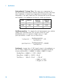
To Calculate Total Measurement Error
The multimeter's accuracy specifications are expressed in the form:
( % of reading + % of range ). In addition to the reading error and range
error, you may need to add additional errors for certain operating
conditions. Check the list below to make sure you include all measurement
errors for a given function. Also, make sure you apply the conditions as
described in the footnotes on the specification pages.
• If you are operating the multimeter outside the temperature range
specified, apply an additional temperature coefficient error.
• For dc voltage, dc current, and resistance measurements, you may need
to apply an additional reading speed error or autozero OFF error.
• For ac voltage and ac current measurements, you may need to apply an
additional low frequency error or crest factor error.
Understanding the " % of reading " Error
The reading error compensates for
inaccuracies that result from the function and range you select, as well as
the input signal level. The reading error varies according to the input level
on the selected range. This error is expressed in percent of reading. The
following table shows the reading error applied to the multimeter's
24–hour dc voltage specification.
Range
Input Level
10 VDC
10 VDC
0.0015
±150 mV
10 VDC
1 VDC
0.0015
±15 mV
10 VDC
0.1 VDC
0.0015
±1.5 mV
34410A/11A/L4411A Service Guide
Reading Error
(% of reading)
Reading Error
(Voltage)
33
1
Specifications
Understanding the " % of range " Error The range error compensates for
inaccuracies that result from the function and range you select. The range
error contributes a constant error, expressed as a percent of range,
independent of the input signal level. The following table shows the range
error applied to the multimeter's 24–hour dc voltage specification.
Range
Input Level
Range Error
(% of range)
Range Error
(Voltage)
10 VDC
10 VDC
0.0004
±40 mV
10 VDC
1 VDC
0.0004
±40 mV
10 VDC
0.1 VDC
0.0004
±40 mV
Total Measurement Error To compute the total measurement error, add the
reading error and range error. You can then convert the total
measurement error to a "percent of input" error or a "ppm
(parts–per–million) of input" error as shown below.
Error Example
Assume that a 5 VDC signal is input to the multimeter on
the 10 V range. Compute the total measurement error using the 90–day
accuracy specifications: ± (0.0020% of reading + 0.0005% of range).
Reading Error = 0.0020% x
Range Error = 0.0005% x
Total Error =
34
5 VDC = 100 mV
10 VDC = 50 mV
100 mV + 50 mV
= \150 mV
= \0.003% of 5 VDC
= \30 ppm of 5 VDC
34410A/11A/L4411A Service Guide
Specifications
1
Interpreting Accuracy Specifications
Transfer Accuracy
Transfer accuracy refers to the error introduced by the multimeter due to
noise and short–term drift. This error becomes apparent when comparing
two nearly–equal signals for the purpose of "transferring" the known
accuracy of one device to the other.
24–Hour Accuracy
The 24–hour accuracy specification indicates the multimeter's relative
accuracy over its full measurement range for short time intervals and
within a stable environment. Short–term accuracy is usually specified for a
24–hour period and for a ±1 °C temperature range.
90–Day and 1–Year Accuracy
These long–term accuracy specifications are valid at the calibration
temperature (Tcal) ± 5 °C temperature range. These specifications include
the initial calibration errors plus the multimeter's long–term drift errors.
Temperature Coefficients
Accuracy is usually specified at the calibration temperature (Tcal) ± 5 °C
temperature range. This is a common temperature range for many
operating environments. You must add additional temperature coefficient
errors to the accuracy specification if you are operating the multimeter
outside the ± 5 °C temperature range (the specification is per °C).
34410A/11A/L4411A Service Guide
35
1
Specifications
Configuring for Highest Accuracy Measurements
The measurement configurations shown below assume that the multimeter
is in its power–on or reset state. It is also assumed that auto–ranging is
enabled to ensure proper full scale range selection.
DC Voltage, DC Current, and Resistance Measurements:
• Select NPLC and 100 (NPLCs) for INTEGRATION.
• Set INPUT Z to HI–Z (for the 100 mV, 1 V, and 10 V ranges) for the best dc
voltage accuracy.
• Use the 4–wire ohms function (W 4W) for the best resistance
measurement accuracy.
• For 2–wire ohms, dc voltage and dc current measurements, set AUTOZERO
to ON to remove thermal EMF and offset errors.
• Null the test lead resistance for 2–wire ohms measurements, and to
remove any interconnection offset for dc voltage measurements.
AC Voltage and AC Current Measurements:
• Set the AC FILTER to 3 Hz: SLOW.
Frequency and Period Measurements:
• Set the GATE TIME to 1 sec.
36
34410A/11A/L4411A Service Guide
Agilent 34410A/11A/L4411A 6½ Digit Multimeter
Service Guide
2
Quick Start
This chapter gives you a quick overview of the 34410A/11A
multimeter’s front panel and basic features. The examples
will help you become familiar with your meter, its measuring
functions. and basic operation.
Basic Multimeter Operations 38
Preparing the Multimeter for Use 38
Using the Front Panel 39
Making Basic Measurements 41
Other Basics of Operation 49
If the Multimeter Does Not Turn On 49
To Replace the Power-Line Fuse (34410A/11A) 50
To Adjust the Carrying Handle (34410A/11A) 51
To Rack Mount the 34410A/11A Multimeter 51
To Rack Mount the L4411A Multimeter 52
Calibration Operation (34410A/11A) 53
To Read the Calibration Count 53
To Read the Calibration Message 54
To Store a Calibration Message 54
To Secure for Calibration 55
To Unsecure for Calibration 56
Agilent Technologies
37
2
Quick Start
Basic Multimeter Operations
This section introduces the basics of the 34410A/11A multimeter, and how
to use it.
Preparing the Multimeter for Use
To verify that your 34410A or 34411A multimeter is ready for use:
1 Check the list of supplied items.
Verify that you have received the following items with your multimeter.
If anything is missing, contact your nearest Agilent Sales Office.
•
•
•
•
•
•
Test Lead Set (34410A/11A only).
Power Cord.
USB 2.0 Cable.
Agilent 34410A/11A/L4411A Product Reference CD–ROM.
Agilent Automation Ready (IO Libraries) CD–ROM.
Certificate of Calibration.
The product documentation, including the Agilent 34410A/11A/L4411A
Programmer’s Reference Help and the product manuals, are included
on the Product Reference CD–ROM. Printed (hardcopy) manuals are
optional, and included only if you ordered them.
2 Connect the power cord and turn on the multimeter.
34410A/11A
The front–panel display will light up while the multimeter
performs its power–on self–test. The multimeter powers up in the dc
voltage function with autoranging enabled (unless a previous user has
configured power–up using a non–default stored state (see Chapter 2,
“Features and Functions” in the Agilent 34410A/11A User’s Guide).
L4411A The front- panel display lights up while the multimeter performs
its power–on self–test. The display briefly shows the model number and
firmware revision code, followed by the instrument MAC address, and
finally the readings and LAN status display.
38
34410A/11A/L4411A Service Guide
Quick Start
2
Using the Front Panel
This section introduces the 34410A/11A multimeter front panel.
Front-Panel Keys
The front panel provides keys to select various functions and operations.
Pressing a measurement function key (e.g.
) selects that function.
Press
to enter the configuration menu for the selected measurement
function.
Most keys have a shifted function printed in blue above the key. To
perform a shifted function, press
, and then press the key that has
the desired label above it.
To view and select menu items, use the menu navigation keypad (for
example the
or
keys). The current (or default) selection is
displayed in FULL BRIGHTNESS. All other choices are displayed in HALF
BRIGHTNESS. The selections on each menu level scroll, but do not wrap.
Arrow annunciators on the second display line indicate additional
selections to the left or right. To accept a selection, press
.
To set numeric parameters, use
to increase or decrease that digit.
34410A/11A/L4411A Service Guide
or
to select a digit, and
or
39
2
Quick Start
Front- Panel Display Shortcuts
Direct front–panel shortcuts are provided for three commonly used display
functions: ranging, digit masking, and integration time.
Ranging.
The multimeter’s manual range can be set directly from the
navigation keypad.
To manually change the current multimeter range, press
or
. The
ManRng annunciator will light, and the selected range (e.g. 100mV RANGE)
will be briefly displayed on the second line.
Digit Masking. The navigation keypad provides a shortcut to mask
(change the number of digits displayed) the reading on the main display,
easing readability.
To enable digit masking during any measurement function, press
or
. DIGIT MASK will be displayed, along with a list of
choices (3.5, 4.5, 5.5, 6.5 and AUTO) on the second display line. Press
or
to scroll through and select one of these settings, and then
press
.
Integration Time (Bandwidth, Gate Time). Four measurement functions
allow you to select the multimeter’s integration time: dc voltage, dc
current, resistance, and temperature. The ac voltage and current
measurements allow you to select the ac signal filter (bandwidth). The
frequency/period function allows you to select gate time. The navigation
keypad provides a shortcut for quickly changing these settings.
• If the multimeter is configured to take the measurement using an
integration time in NPLCs, pressing
or
during front panel
measurement operations will increase or decrease the integration time
setting.
• If either the ac voltage or ac current measurement function is selected,
pressing
or
during front panel measurement operations will
increase or decrease the bandwidth setting.
• If the frequency/period measurement function is selected, pressing
or
during front panel measurement operations will increase or
decrease the gate time setting.
40
34410A/11A/L4411A Service Guide
Quick Start
2
Making Basic Measurements
This section introduces the many types of measurements that you can
make with your 34410A/11A multimeter, and how to make connections for
each measurement. Most basic measurements can be taken using the
factory default settings. A more complete description of all multimeter
functions, measurement parameter configuration and remote interface
operation is provided in Chapter 2.
For each measurement, connect the test leads as shown. The test lead
connections are the same for the front or rear set of terminals.
Before making test lead connections, use the Front/Rear button on the
front panel to select either the front or rear set of terminals. The Rear
annunciator lights if the rear terminals are selected.
WA R N I N G
Do not press the Front/Rear button while signals are present on either the front or rear
set of terminals. Switching while high voltages or currents are present can cause
instrument damage, and may increase the risk of electric shock.
34410A/11A/L4411A Service Guide
41
2
Quick Start
To Measure DC Voltage
Press
to select the dc voltage function.
• Ranges: 100 mV, 1 V, 10 V, 100 V, 1000 V
• Configurable parameters: INTEGRATION, RANGE, INPUT Z (input impedance),
AUTO ZERO, NULL, and NULL VALUE
Connect test leads as shown:
DC Voltage
To Measure AC Voltage
Press
to select the ac voltage function.
• Ranges: 100 mV, 1 V, 10 V, 100 V, 750 V
• AC Technique: true–RMS, ac–coupled
• Configurable parameters: AC FILTER, RANGE, NULL and NULL VALUE
Connect test leads as shown:
42
AC Voltage
34410A/11A/L4411A Service Guide
Quick Start
2
To Measure DC Current
Press
to select the dc current function.
• Ranges: 100 mA, 1 mA, 10 mA, 100 mA, 1 A, 3 A
• Configurable parameters: INTEGRATION, RANGE, AUTO ZERO, NULL, and NULL
VALUE
Connect test leads as shown:
DC Current
To Measure AC Current
Press
to select the ac current function.
• Ranges: 100 mA, 1 mA, 10 mA, 100 mA, 1 A, 3 A
• AC Technique: true–RMS, ac–coupled
• Configurable parameters: AC FILTER, RANGE, NULL and NULL VALUE
Connect test leads as shown:
AC Current
34410A/11A/L4411A Service Guide
43
2
Quick Start
To Make a 2-Wire Resistance Measurement
Press
to select the 2- wire resistance function.
• Ranges: 100 W, 1 kW, 10 kW, 100 kW, 1 MW, 10 MW, 100 MW, 1 GW
• Configurable parameters: INTEGRATION, RANGE, OFFSET COMP, AUTO ZERO, NULL,
and NULL VALUE
Connect test leads as shown:
Resistance
To null–out the test lead resistance:
1 Connect one end of the test leads at the meter, and short the probe
ends together.
2 Press null.
3 Connect the probe ends to the test circuit, and measure the corrected
resistance value.
To Make a 4-wire Resistance Measurement
Press
to select the 4- wire resistance function.
• Ranges: 100 W, 1 kW, 10 kW, 100 kW, 1 MW, 10 MW, 100 MW, 1 GW
• Configurable parameters: INTEGRATION, RANGE, OFFSET COMP, NULL, and NULL
VALUE
Connect test leads as shown:
Resistance
All 4- wire resistance measurements are made with auto- zero on.
44
34410A/11A/L4411A Service Guide
Quick Start
2
To Measure Frequency
Press
to select the frequency function.
• Measurement band: 3 Hz to 300 kHz
• Input signal range: 100 mVAC to 750 VAC
• Technique: reciprocal counting
• Configurable parameters: GATE TIME, RANGE, AC FILTER, NULL and NULL VALUE
Connect test leads as shown:
AC Signal
To Measure Period
Press
to select the frequency function. Then press
PERIOD from the menu.
•
•
•
•
and select
Measurement band: 0.33 s to 3.3 ms
Input signal range: 100 mVAC to 750 VAC
Technique: reciprocal counting
Configurable parameters: GATE TIME, RANGE, AC FILTER, NULL and NULL VALUE
Connect test leads as shown:
AC Signal
34410A/11A/L4411A Service Guide
45
2
Quick Start
To Measure Capacitance
Press
to select the capacitance function.
• Ranges: 1 nF, 10 nF, 100 nF, 1 mF, 10 mF
• Configurable parameters: RANGE, NULL, and NULL VALUE
Connect test leads as shown:
Capacitance
To null–out the test lead capacitance:
1 Disconnect the + lead’s probe end from the test circuit, and leave open.
2 Press null.
3 Reconnect the + lead’s probe end to the test circuit, and measure the
corrected capacitance value.
46
34410A/11A/L4411A Service Guide
Quick Start
2
To Make a 2-Wire Temperature Measurement
Press
to select the temperature function. Then press
and select RTD-2W or THERMISTOR-2W from the menu.
• Probe types: 2.2 kW, 5 kW, 10 kW thermistors; 0.00385%/ºC RTD
• Configurable parameters: PROBE TYPE, THERMISTOR or RTD value, AUTO ZERO,
OFFSET COMP (RTD probes only), INTEGRATION, UNITS, NULL, and NULL VALUE
Connect test leads as shown:
Thermistor or RTD
To Make a 4-Wire Temperature Measurement
Press
to select the temperature function. Then press
and select RTD-4W or THERMISTOR-4W from the menu.
• Probe types: 2.2 kW, 5 kW, 10 kW thermistors; 0.00385%/ºC RTD
• Configurable parameters: PROBE TYPE, THERMISTOR or RTD value, OFFSET COMP
(RTD probes only), INTEGRATION, UNITS, NULL, and NULL VALUE
Connect test leads as shown:
Thermistor or RTD
All 4- wire temperature measurements are made with auto- zero on.
34410A/11A/L4411A Service Guide
47
2
Quick Start
To Test Continuity
Press
to select the continuity function.
• Test current source: 1 mA
• Beeper Threshold: beeps below 10W
Connect test leads as shown:
Open or Closed Circuit
To Check Diodes
Press
to select the diode test function.
• Test current source: 1 mA
• Beeper Threshold: 0.3V ~ voltagemeasured ~ 0.8V (not adjustable)
Connect test leads as shown:
Forward Bias
The diode check function is used to indicate correct diode operation;
closed–circuit on forward bias and open–circuit on reverse–bias.
48
34410A/11A/L4411A Service Guide
Quick Start
2
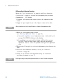
Other Basics of Operation
This section covers basic troubleshooting and general use.
If the Multimeter Does Not Turn On
Use the following steps to help solve problems you might encounter when
turning on the multimeter. If you need more help, see the Service Guide
for instructions on returning the multimeter to Agilent for service.
1 Verify that there is ac power to the multimeter.
First, verify that the multimeter’s Power switch is in the “On” position.
Also, make sure that the power cord is firmly plugged into the power
module on the rear panel. You should also make sure that the power
source you plugged the multimeter into is energized.
2 Verify the power–line voltage setting (34410A/11A only).
The line voltage is set to the proper value for your country when the
multimeter is shipped from the factory. Change the voltage setting if it is
not correct. The settings are: 100, 120, 220, or 240 Vac (for 230 Vac
operation, use the 220 Vac setting).
See “To Replace the Power- Line Fuse (34410A/11A)” on page 50 if you
need to change the line–voltage setting.
3 Verify that the power–line fuse is good (34410A/11A only).
The multimeter is shipped from the factory with a power–line fuse
installed. The supplied fuse is a 250 mAT, 250V, slow–blow, 5x20mm
fuse, Agilent part number 2110–0817. If you determine that the fuse is
faulty, replace it with one of the same size and rating.
See “To Replace the Power- Line Fuse (34410A/11A)” on page 50 if you
need to replace the power–line fuse.
The current input path is also fused. The supplied fuse is a 3 AT, 250V,
slow–blow, 5x20mm fuse, Agilent part number 2110–0780, and is housed
in a standard screw–in fuse holder on the the rear panel. If you determine
that the fuse is faulty, replace it with one of the same size and rating.
34410A/11A/L4411A Service Guide
49
2
Quick Start
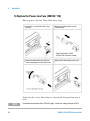
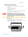
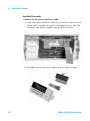
To Replace the Power-Line Fuse (34410A/11A)
Remove power cord first. Then follow these steps:
Depress tab (1) and pull fuse holder (2) from
rear panel.
Remove line-voltage selector from fuse
holder assembly.
Agilent Part Number 2110-0817
(250 mAT, 250V, slow-blow, 5x20mm)
Rotate line-voltage selector and reinstall so
correct voltage appears in fuse holder window.
Replace fuse holder assembly in rear panel.
Verify that the correct line voltage is selected and the power- line fuse is
good.
NOTE
50
For multimeter operations with a 230 VAC supply, set the line–voltage selector to 220V.
34410A/11A/L4411A Service Guide
Quick Start
2
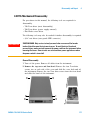
To Adjust the Carrying Handle (34410A/11A)
To adjust the position, grasp the handle by the sides and pull outward.
Then, rotate the handle to the desired position.
Bench-Top Viewing Positions
Carrying Position
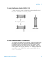
To Rack Mount the 34410A/11A Multimeter
You can mount the 34410A/11A in a standard 19–inch rack cabinet using
the available rack–mount kits. Instructions and mounting hardware are
included with each kit. Any Agilent System II (half- width, 2U height)
instrument of either the 272.3 mm or the 348.3 mm depth can be rack
mounted side–by–side with the 34410A/11A. For example, a 34410A/11A
and a 34401A, or two 34410A/11As, can be mounted side–by–side, as
shown on the next page.
34410A/11A/L4411A Service Guide
51
2
Quick Start
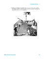
You must remove the carrying handle, and the front and rear rubber
bumpers, before rack mounting an instrument.
To remove each bumper, stretch a corner and slide it off.
To remove the handle, rotate it to the vertical position and pull the ends outward.
To rack mount a single instrument, order adaptor kit 5063-9240
To rack mount two instruments side-by-side, order lock-link kit
5061-8769 and flange kit 5063-9212
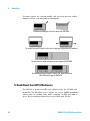
To Rack Mount the L4411A Multimeter
The L4411A is mounted in EIA rack cabinets using the Y1160A rack
mount kit. The kit allows you to mount one or two L4400 instruments
side- by- side on a sliding shelf, while occupying one EIA rack unit of
space. Rack mounting instructions are provided with the kit
52
34410A/11A/L4411A Service Guide
Quick Start
2
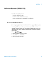
Calibration Operation (34410A/11A)
From the front panel you can:
• Read the calibration count
• Read and set the calibration message.
• Secure and unsecure the instrument for calibration.
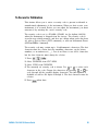
To Read the Calibration Count
You can query the instrument to determine how many calibrations have
been performed. Note that your instrument was calibrated before it left
the factory. When you receive your instrument, read the count to
determine its initial value. The count value increments by one for each
calibration point, and a complete calibration will increase the value by
many counts.
1 Press
.
2 Select CALIBRATION from UTILITY MENU.
3 Select COUNT from CALIBRATION.
4 Make note of the CAL COUNT.
34410A/11A/L4411A Service Guide
53
2
Quick Start
To Read the Calibration Message
The instrument allows you to store a message in calibration memory. For
example, you can store such information as the date when the last
calibration was performed, the date when the next calibration is due, the
instrument's serial number, or even the name and phone number of the
person to contact for a new calibration.
You can record a calibration message only when the instrument is
unsecured. You can read the calibration message whether the instrument
is secured or unsecured.
1 Press
.
2 Select CALIBRATION from UTILITY MENU.
3 Select MESSAGE from CALIBRATION.
To Store a Calibration Message
You can record a calibration message only when the instrument is
unsecured (see “To Unsecure for Calibration” on page 56).
1 Press
.
2 Select CALIBRATION from UTILITY MENU.
3 Select MESSAGE from CALIBRATION.
4 Use
or
to select each character in the message. Change the
characters by pressing
or
to cycle through all the possible
display characters. The full alphabet is available as well as the digits 0
through 9, spaces, and special characters.
5 Press
54
when done.
34410A/11A/L4411A Service Guide
Quick Start
2
To Secure for Calibration
This feature allows you to enter a security code to prevent accidental or
unauthorized adjustments of the instrument. When you first receive your
instrument, it is secured. Before you can adjust the instrument, you must
unsecure it by entering the correct security code.
The security code is set to AT34410 (AT34411 for the Agilent 34411A)
when the instrument is shipped from the factory. The security code is
stored in non–volatile memory, and does not change when power has been
off, after a Factory Reset (*RST command), or after an Instrument Preset
(SYSTem:PRESet command).
The security code may contain up to 12 alphanumeric characters. The first
character must be a letter, but the remaining characters can be letters,
numbers, or an underscore ( _ ). You do not have to use all 12 characters
but the first character must always be a letter.
1 Press
.
2 Select CALIBRATION from UTILITY MENU.
3 Select SECURE from CALIBRATION.
4 The currently set security code is shown. Use
or
to select each
character in the code. Change the characters by pressing
or
to
cycle through all the possible display characters. The full alphabet is
available as well as the digits 0 through 9. The first character must be
a letter.
5 Press
34410A/11A/L4411A Service Guide
when done.
55
2
Quick Start
To Unsecure for Calibration
Before you can adjust the instrument, you must unsecure it by entering
the correct security code. The security code is set to AT34410 when the
instrument is shipped from the factory. The security code is stored in
non–volatile memory, and does not change when power has been off, after
a Factory Reset (*RST command), or after an Instrument Preset
(SYSTem:PRESet command).
The security code may contain up to 12 alphanumeric characters. The first
character must be a letter, but the remaining characters can be letters,
numbers, or an underscore ( _ ). You do not have to use all 12 characters
but the first character must always be a letter.
NOTE
If you forget your security code, you can disable the security feature by applying a
temporary short inside the instrument as described in “To Unsecure the Instrument
Without the Security Code” on page 75
1 Press
2 UTILITY MENU > CALIBRATION > UNSECURE > ENTER CODE
3 Use
or
to set each character in the code. Change the characters
by pressing
or
to cycle through all the possible display
characters. The full alphabet is available as well as the digits 0 through
9. The first character must be a letter.
4 Press
when done. The CAL UNSECURED message appears briefly.
To Re-secure
To re- secure the multimeter after a calibration, reverse the process:
Press
UTILITY MENU > CALIBRATION > SECURE > SET CAL CODE
The previous calibration code is proposed. Press
to accept that code,
or use the navigation keypad to enter a new code. The CAL SECURED
message appears briefly when you press the
key.
56
34410A/11A/L4411A Service Guide
Agilent 34410A/11AL4411A 6½ Digit Multimeter
Service Guide
3
Calibration Procedures
Agilent Technologies Calibration Services 58
Calibration Interval 58
Adjustment is Recommended 58
Time Required for Calibration 59
Automating Calibration Procedures 59
Recommended Test Equipment 60
Performance Verification Tests 60
Input Connections 62
Test Considerations 63
Verification Tests 64
Calibration Security 75
Calibration Message 77
Calibration Count 77
Calibration Process 78
Aborting a Calibration in Progress 79
Adjustments 80
This manual contains procedures for verification of the instrument’s
performance and adjustment (calibration).
Closed–Case Electronic Calibration. The instrument features closed–case
electronic calibration. No internal mechanical adjustments are required.
The instrument calculates correction factors based upon the input
reference value you set. The new correction factors are stored in
non–volatile memory until the next calibration adjustment is performed.
Non–volatile EEPROM calibration memory does not change when power
has been off or after a remote interface reset.
Agilent Technologies
57
3
Calibration Procedures
Agilent Technologies Calibration Services
Agilent Technologies offers calibration services at competitive prices. When
your instrument is due for calibration, contact your local Agilent Service
Center for recalibration. See “Types of Service Available” on page 105 for
information on contacting Agilent.
Calibration Interval
The instrument should be calibrated on a regular interval determined by
the measurement accuracy requirements of your application.
A 1–year interval is adequate for most applications. Accuracy
specifications will remain valid only if adjustment is made at regular
calibration intervals. Accuracy specifications are not valid beyond the
1–year calibration interval. Agilent does not recommend extending
calibration intervals beyond 2 years for any application.
Adjustment is Recommended
Specifications are only valid within the period stated from the last
adjustment. Whatever calibration interval you select, Agilent recommends
that complete re–adjustment always be performed at the calibration
interval. This is necessary to ensure that the instrument will remain
within specification for the next calibration interval. This criteria for
re–adjustment provides the best long–term stability.
Performance data measured during Performance Verification Tests does
not mean that the instrument will remain within these limits unless the
adjustments are performed.
Use the Calibration Count feature (see page 77) to verify that all
adjustments have been performed.
58
34410A/11A/L4411A Service Guide
Calibration Procedures
3
Time Required for Calibration
The instrument can be automatically calibrated under computer control.
With computer control you can perform the complete calibration
procedure and performance verification tests in less than 30 minutes once
the instrument is warmed–up (see Test Considerations on page 63).
Automating Calibration Procedures
The adjustment procedures provided in this Service Guide demonstrate
front panel adjustment. You can automate the complete verification and
adjustment procedures outlined in this manual. You can program the
instrument configurations specified for each test over the remote interface.
You can then enter read back verification data into a test program and
compare the results to the appropriate test limit values.
The instrument must be unsecured prior to initiating the calibration
procedure (see “Calibration Security” on page 75).
Refer to the Agilent 34410A/11A/L4411A Programmer's Reference Help for
information on SCPI programming for the multimeter. This is a standard
Windows online help system, provided with the multimeter on the Agilent
34410A/11A/L4411A Product Reference CD–ROM. It is also downloadable
from the Web. See either product page:
www.agilent.com/find/34410A
www.agilent.com/find/34411A
www.agilent.com/find/L4411A
34410A/11A/L4411A Service Guide
59
3
Calibration Procedures
Recommended Test Equipment
The test equipment recommended for the performance verification and
adjustment procedures is listed below. If the exact instrument is not
available, substitute calibration standards of equivalent accuracy.
A suggested alternate method would be to use the Agilent 3458A 8½–digit
Digital Multimeter to measure less accurate yet stable sources. The output
value measured from the source can be entered into the instrument as the
target calibration value.
Application
Recommended Equipment
Accuracy Requirements
Zero Calibration
DC Voltage
DC Current
Resistance
AC Voltage
AC Current
Frequency
Capacitance
Agilent 34172B (2 recommended)*
Fluke 5720A
Fluke 5720A
Fluke 5720A
Fluke 5720A
Fluke 5720A
Agilent 33220A
IET SCA–1µF
4 –terminal low thermal short
<1/5 instrument 24 hour spec
<1/5 instrument 24 hour spec
<1/5 instrument 24 hour spec
<1/5 instrument 24 hour spec
<1/5 instrument 24 hour spec
<1/5 instrument 24 hour spec
<1/5 instrument 24 hour spec
* Only one 34172B is required for the L4411A.
Performance Verification Tests
Use the Performance Verification Tests to verify the measurement
performance of the instrument. The performance verification tests use the
instrument’s specifications listed in the Product Data Sheet.
You can perform four different levels of performance verification tests:
• Self–Test. A series of internal verification tests that give a high
confidence that the instrument is operational.
• Quick Verification. A combination of the internal self–tests and
selected verification tests.
• Performance Verification Tests. An extensive set of tests that are
recommended as an acceptance test when you first receive the
instrument or after performing adjustments.
• Additional Verification Tests. Tests not performed with every calibration.
Perform these tests to verify additional specifications or functions of
the instrument.
60
34410A/11A/L4411A Service Guide
Calibration Procedures
3
Self–Test
A brief power–on self–test occurs automatically whenever you turn on the
instrument. This limited test assures that the instrument is capable of
operation.
• During the self–test all display segments and annunciators are lit.
• 34410A/11A If the self–test fails, the ERROR annunciator turns on.
Read any errors using the front panel Utility menu (select SCPI ERRORS), or
use the SYSTem:ERRor? command query from the remote interface.
L4411A If the self–test fails, an error message will appear in the
displayn. Use the SYSTem:ERRor? command query from the remote
interface.
If repair is required, contact an Agilent Service Center.
• If all tests pass, you have a high confidence (~90%) that the instrument
is operational.
• You can initiate a more complete self test by sending the *TST?
command to the instrument. This command returns a “+0” if all the
self–tests pass, or a “+1” if a failure occurred. This command may take
up to 30 seconds to complete. You may need to set an appropriate
interface time–out value.
Quick Performance Check
The quick performance check is a combination of internal self–test and an
abbreviated performance test (specified by the letter Q in the performance
verification tests). This test provides a simple method to achieve high
confidence in the instrument’s ability to functionally operate and meet
specifications. These tests represent the absolute minimum set of
performance checks recommended following any service activity. Auditing
the instrument’s performance for the quick check points (designated by a
Q) verifies performance for “normal” accuracy drift mechanisms. This test
does not check for abnormal component failures.
To perform the quick performance check, do the following:
• Perform a self–test as described on page 61.
• Perform only the performance verification tests indicated with the letter
Q.
34410A/11A/L4411A Service Guide
61
3
Calibration Procedures
If the instrument fails the quick performance check, adjustment or repair
is required.
Performance Verification Tests
The performance verification tests are recommended as acceptance tests
when you first receive the instrument. The acceptance test results should
be compared against the 90 day test limits. You should use the 24–hour
test limits only for verification within 24 hours after performing the
adjustment procedure. After acceptance, you should repeat the
performance verification tests at every calibration interval.
If the instrument fails performance verification, adjustment or repair is
required.
Adjustment is recommended at every calibration interval. If adjustment is
not made, you must establish a ‘guard band’, using no more than 80% of
the specifications, as the verification limits.
Input Connections
Test connections to the instrument are best accomplished using an Agilent
Technologies 34172B calibration short for low–thermal offset
measurements and a 34171B DMM connector configured to interface to the
calibrator output. Shielded, twisted–pair, Teflon interconnect cables of
minimum length are recommended between the calibrator and the
multimeter. HI and HI Sense should be a twisted pair. LO and LO Sense
should be a twisted pair. Cable shields should be earth ground referenced.
This configuration is recommended for noise reduction and settling time
performance during calibration.
62
34410A/11A/L4411A Service Guide
Calibration Procedures
3
Test Considerations
Errors may be induced by ac signals present on the input leads during a
self–test. Long test leads can also act as an antenna causing pick–up of ac
signals.
For optimum performance, all procedures should comply with the
following recommendations:
• Assure that the calibration ambient temperature (Tcal) is stable and
between 18 °C and 28 °C. Ideally the calibration should be performed
at 23 °C ±2 °C.
• Assure ambient relative humidity is less than 80%.
• Allow a 90 minute warm–up period with a copper short connected.
• Use shielded twisted pair Teflon–insulated cables to reduce settling and
noise errors. Keep the input cables as short as possible.
• Connect the input cable shields to earth ground. Except where noted in
the procedures, connect the calibrator LO source to earth ground at the
calibrator. It is important that the LO to earth ground connection be
made at only one place in the circuit to avoid ground loops.
Because the instrument is capable of making highly accurate
measurements, you must take special care to ensure that the calibration
standards and test procedures used do not introduce additional errors.
Ideally, the standards used to verify and adjust the instrument should be
an order of magnitude more accurate than each instrument range full
scale error specification.
For the dc voltage, dc current, and resistance gain verification
measurements, you should take care to ensure the calibrator’s “0” output
is correct. You will need to set the offset for each range of the measuring
function being verified.
34410A/11A/L4411A Service Guide
63
3
Calibration Procedures
Verification Tests
Zero Offset Verification
This procedure is used to check the zero offset performance of the
instrument. Verification checks are only performed for those functions and
ranges with unique offset calibration constants. Measurements are checked
for each function and range as described in the procedure on the next
page.
Zero Offset Verification Procedure (34410A/11A)
1 Make sure you have read “Test Considerations” on page 63.
2 Install the 34172B Calibration Short (or equivalent) on the front panel
input terminals. Select the Front input terminals with the Front/Rear
switch.
3 Select each function and range in the order shown in the table below.
Make a measurement and return the result. Compare measurement
results to the appropriate test limits shown in the table on the next
page.
4 Install the 34172B Calibration Short (or equivalent) on the rear panel
input terminals. Select the Rear input terminals with the Front/Rear
switch.
5 Select each function and range in the order shown in the table below.
Make a measurement and return the result. Compare measurement
results to the appropriate test limits shown in the table below.
Zero Offset Verification Procedure (L4411A only)
1 Make sure you have read “Test Considerations” on page 63.
2 Install the 34172B Calibration Short (or equivalent) on the input
terminals.
3 Select each function and range in the order shown in the table below.
Make a measurement and return the result. Compare measurement
results to the appropriate test limits shown in the table on the next
page.
64
34410A/11A/L4411A Service Guide
Calibration Procedures
Input
Function[1]
Range
Quick
Check
Error from Nominal
24 hour
90 day
1 year
100 µA
± 0.02 µA
± 0.025 µA
± 0.025 µA
Open
1 mA
± 0.060 µA
± 0.060 µA
± 0.060 µA
Open
10 mA
± 2 µA
± 2 µA
± 2 µA
Open
100 mA
± 4 µA
± 5 µA
± 5 µA
Open
1A
± 60 µA
± 100 µA
± 100 µA
Open
3A
± 600 µA
± 600 µA
± 600 µA
± 3 µV
± 3.5 µV
± 3.5 µV
Open
Short
DC Current
DC Volts
100 mV
Q
Q
Short
1V
± 6 µV
± 7 µV
± 7 µV
Short
10 V
± 40 µV
± 50 µV
± 50 µV
Short
100 V
± 600 µV
± 600 µV
± 600 µV
Short
1000 V
± 6 mV
± 6 mV
± 6mV
Short
4–Wire Ohms[2] 100 Ω
± 3 mΩ
± 4 mΩ
± 4 mΩ
± 5 mΩ
± 10 mΩ
± 10 mΩ
± 50 mΩ
± 100 mΩ
± 100 mΩ
Short
1 kΩ
Short
10 kΩ
Short
100 kΩ
± 500 mΩ
±1Ω
±1Ω
Short
1 MΩ
± 10 Ω
± 10 Ω
± 10 Ω
Short
10 MΩ
± 100 Ω
± 100 Ω
± 100 Ω
Short
100 MΩ
± 1 kΩ
± 1 kΩ
± 1 kΩ
Q
3
[1] Select 100 NPLC.
[2] Specifications are for 4–wire Ohms function or 2–wire Ohms function using math null. Without
math null, add 0.2 Ω additional error in the 2–wire Ohm function.
Q: Quick performance verification test points.
34410A/11A/L4411A Service Guide
65
3
Calibration Procedures
Gain Verification
This procedure is used to check the “full scale” reading accuracy of the
instrument. Verification checks are performed only for those functions and
ranges with unique gain calibration constants.
DC Volts Gain Verification Test
1 Make sure you have read “Test Considerations” on page 63.
2 Connect the calibrator to the input terminals.
a For the 34410A/11A use the front panel input terminals and select
the Front input terminals with the Front/Rear switch.
3 Select each function and range in the order shown below. Provide the
input shown in the table below.
4 Make a measurement and return the result. Compare measurement
results to the appropriate test limits shown in the table. (Be certain to
allow for appropriate source settling when using the Fluke 5720A.)
Input
Voltage
100 mV
[1]
Function
DC Volts
Range
Quick
Check
Error from Nominal
24 hour
90 day
1 year
100 mV
± 6 µV
± 7.5 µV
± 8.5 µV
–100 mV
100 mV
± 6 µV
± 7.5 µV
± 8.5 µV
1V
1V
± 26 µV
± 37 µV
± 42 µV
10 V
10 V
± 190 µV
± 250 µV
± 350 µV
–10 V
10 V
± 190 µV
± 250 µV
± 350 µV
100 V
100 V
± 2.6 mV
± 4.1 mV
± 4.6 mV
1000 V
1000 V
± 26 mV
± 41 mV
± 46 mV
Q
Q
[1] Select 100 NPLC.
Q: Quick performance verification test points.
66
34410A/11A/L4411A Service Guide
Calibration Procedures
3
DC Current Gain Verification Test
1 Make sure you have read “Test Considerations” on page 63
2 Connect the calibrator to the input terminals.
a For the 34410A/11A use the front panel input terminals and select
the Front input terminals with the Front/Rear switch.
3 Select each function and range in the order shown below. Provide the
input shown in the table below.
4 Make a measurement and return the result. Compare measurement
results to the appropriate test limits shown in the table. (Be certain to
allow for appropriate source settling when using the Fluke 5720A.)
Input
Current
100 µA
Function[1]
Range
Quick
Check
Error from Nominal
24 hour
90 day
1 year
100 µA
± 0.03 µA
± 0.065 µA
± 0.075 µA
1 mA
1 mA
± 0.13 µA
± 0.36 µA
± 0.56 µA
10 mA
10 mA
± 2.7 µA
± 5 µA
± 7 µA
100 mA
100 mA
± 14 µA
± 35 µA
± 55 µA
1A
1A
± 560 µA
± 900 µA
± 1.1 mA
2A
3A
± 2.6 mA
± 3 mA
± 3.6 mA
DC Current
Q
Q
[1] Select 100 NPLC.
Q: Quick performance verification test points.
34410A/11A/L4411A Service Guide
67
3
Calibration Procedures
Ohms Gain Verification Test
Configuration:
4–Wire Ohms (CONFigure:FRESistance)
1 Make sure you have read “Test Considerations” on page 63.
2 Set the 4- Wire Ohms function.
3 Connect the calibrator to the input terminals.
a For the 34410A/11A use the front panel input terminals and select
the Front input terminals with the Front/Rear switch.
4 Select each range in the order shown below. Provide the resistance
value indicated. Compare measurement results to the appropriate test
limits shown in the table. (Be certain to allow for appropriate source
settling.)
Input
Resistance
100 Ω
Function [1]
4–Wire Ohms
Range
Quick
Check
100 Ω
Q
Error from Nominal
24 hour
90 day
1 year
± 6 mΩ
± 12 mΩ
± 14 mΩ
± 25 mΩ
± 80 mΩ
± 110 mΩ
1 kΩ
1 kΩ
10 kΩ
10 kΩ
± 250 mΩ
± 800 mΩ
± 1.1 Ω
100 kΩ
100 kΩ
± 2.5 Ω
±8Ω
± 11 Ω
1 MΩ
1 MΩ
± 30 Ω
± 110 Ω
± 130 Ω
10 MΩ
10 MΩ
± 1.1 kΩ
± 3.1 kΩ
± 4.1 kΩ
100 MΩ[2]
100 MΩ
± 201 kΩ
± 601 kΩ
± 801 kΩ
Q
[1] Select 100 NPLC.
[2] Verify only, no adjustment. 2–Wire Ohms.
Q: Quick performance verification test points.
68
34410A/11A/L4411A Service Guide
Calibration Procedures
3
Frequency Gain Verification Test
Configuration:
Frequency (CONFigure:FREQuency DEF, MIN)
1 Make sure you have read “Test Considerations” on page 63.
2 Select the Frequency function, default range, and minimum resolution
(1 second aperture).
3 Connect the Agilent 33220A to the input terminals.
a For the 34410A/11A use the front panel input terminals and select
the Front input terminals with the Front/Rear switch.
4 Select each range in the order shown below. Provide the input voltage
and frequency indicated. Compare measurement results to the
appropriate test limits shown in the table. (Be certain to allow for
appropriate source settling.)
Input
Vrms
Frequency
Range
10 mV
40 Hz
100 mV
10 V
10 kHz
10 V
Quick
Check
Q
Error from Nominal
24 hour
90 day
1 year
± 20 mHz
± 24 mHz
± 28 mHz
± 0.5 Hz
± 0.6 Hz
± 0.7 Hz
Q: Quick performance verification test points.
34410A/11A/L4411A Service Guide
69
3
Calibration Procedures
AC Volts Verification Test
Configuration:
1
2
3
4
AC Volts (CONFigure[:VOLTage]:AC)
LF 3 HZ:SLOW ([SENSe:]VOLTage:AC:BANDwidth 3)
Make sure you have read “Test Considerations” on page 63.
Connect the calibrator to the input terminals.
a For the 34410A/11A use the front panel input terminals and select
the Front input terminals with the Front/Rear switch.
Set the AC Volts function and the 3 Hz input filter. With the slow filter
selected, each measurement takes 2.5 seconds to complete.
Select each range in the order shown below. Provide the indicated input
voltage and frequency. Compare measurement results to the appropriate
test limits shown in the table. (Be certain to allow for appropriate
source settling.)
Input
Vrms
Frequency
Quick
Range
100 mV
1 kHz
100 mV
100 mV
50 kHz
100 mV
100 mV
300 kHz
1V
Check
Error from Nominal
24 hour
90 day
1 year
± 40 µV
± 80 µV
± 90 µV
± 90 µV
± 140 µV
± 150 µV
100 mV
± 1.50 mV
± 1.70 mV
± 1.70 mV
1 kHz
1V
± 400 µV
± 800 µV
± 900 µV
1V
50 kHz
1V
± 900 µV
± 1.4 mV
± 1.5 mV
1V
300 kHz
1V
± 15 mV
± 17 mV
± 17 mV
10 V
10 Hz
10 V
± 4.03 mV
± 8.03 mV
± 9.03 mV
10 V
1 kHz
10 V
± 4 mV
± 8 mV
± 9 mV
10 V
50 kHz
10 V
± 9 mV
± 14 mV
± 15 mV
10 V
300 kHz
10 V
± 150 mV
± 170 mV
± 170 mV
100 V
1 kHz
100 V
± 40 mV
± 80 mV
± 90 mV
100 V
50 kHz
100 V
± 90 mV
± 140 mV
± 150 mV
50 V
300 kHz
100 V
±1V
± 1.1 V
± 1.1 V
750 V
1 kHz
750 V
± 615 mV
± 915 mV
± 990 mV
210 V
50 kHz
750 V
± 405 mV
± 564 mV
± 585 mV
70 V
300 kHz
750 V
± 4.45 V
± 4.59 V
± 4.59 V
Q
Q
Q
Q: Quick performance verification test points.
70
34410A/11A/L4411A Service Guide
Calibration Procedures
3
AC Current Verification Test
Configuration:
AC Current (CONFigure:CURRent:AC)
LF 3 HZ:SLOW ([SENSe:]CURRent:AC:BANDwidth 3)
1 Make sure you have read “Test Considerations” on page 63.
2 Connect the calibrator to the input terminals.
a For the 34410A/11A use the front panel input terminals and select
the Front input terminals with the Front/Rear switch.
3 Set the AC Current function and the 3 Hz input filter. With the slow
filter selected, each measurement takes 1.7 seconds to complete.
4 Select each range in the order shown below. Provide the input current
and frequency indicated. Compare measurement results to the
appropriate test limits shown in the table. (Be certain to allow for
appropriate source settling.)
Input
Current, rms
Frequency
Range
100 µA
1 kHz
100 µA
100 µA
5 kHz
100 µA
1 mA
1 kHz
1 mA
Quick
Check
Error from Nominal
24 hour
90 day
1 year
± 0.14 µA
± 0.14 µA
± 0.14 µA
± 0.14 µA
± 0.14 µA
± 0.14 µA
1 mA
± 1.4 µA
± 1.4 µA
± 1.4 µA
5 kHz
1 mA
± 1.4 µA
± 1.4 µA
± 1.4 µA
10 mA
1 kHz
10 mA
± 14 µA
± 14 µA
± 14 µA
10 mA
10 kHz
10 mA
± 24 µA
± 24 µA
± 24 µA
100 mA
1 kHz
100 mA
± 140 µA
± 140 µA
± 140 µA
100 mA
10 kHz
100 mA
± 240 µA
± 240 µA
± 240 µA
1A
1 kHz
1A
± 1.4 mA
± 1.4 mA
± 1.4 mA
1A
5 kHz
1A
± 1.4 mA
± 1.4 mA
± 1.4 mA
2A
1 kHz
3A
± 4.8 mA
± 4.8 mA
± 4.8 mA
2A
5 kHz
3A
± 4.8 mA
± 4.8 mA
± 4.8 mA
Q
Q: Quick performance verification test points.
34410A/11A/L4411A Service Guide
71
3
Calibration Procedures
Additional AC Voltage Performance Verification Tests
Configuration:
AC Volts (CONFigure[:VOLTage]:AC)
LF 3 HZ:SLOW ([SENSe:]VOLTage:AC:BANDwidth 3)
1 Make sure you have read “Test Considerations” on page 63.
2 Connect the calibrator to the input terminals.
a For the 34410A/11A use the front panel input terminals and select
the Front input terminals with the Front/Rear switch.
3 Set the AC Volts function and the 3 Hz input filter. With the slow filter
selected, each measurement takes 2.5 seconds to complete.
4 Select each range in the order shown below. Provide the indicated input
voltage and frequency. Compare measurement results to the appropriate
test limits shown in the table. (Be certain to allow for appropriate
source settling.)
Input
Vrms
72
Frequency
Error from Nominal
Range
24 hour
90 day
1 year
1V
10 Hz
1V
± 430 µV
± 830 µV
± 930 µV
1V
1 kHz
1V
± 400 µV
± 800 µV
± 900 µV
1V
20 kHz
1V
± 400 µV
± 800 µV
± 900 µV
1V
50 kHz
1V
± 900 µV
± 1.4 mV
± 1.5 mV
1V
100 kHz
1V
± 2.8 mV
± 3.8 mV
± 4.8 mV
1V
300 kHz
1V
± 15 mV
± 17 mV
± 17 mV
10 V
1 kHz
10 V
± 4 mV
± 8 mV
± 9 mV
1V
1 kHz
10 V
± 2.2 mV
± 3.5 mV
± 3.6 mV
0.1 V
1 kHz
10 V
± 2.02 mV
± 3.05 mV
± 3.06 mV
34410A/11A/L4411A Service Guide
Calibration Procedures
3
Additional AC Current Performance Verification Tests
Configuration:
AC Current (CONFigure:CURRent:AC)
LF 3 HZ:SLOW ([SENSe:]CURRent:AC:BANDwidth 3)
1 Make sure you have read “Test Considerations” on page 63
2 Connect the calibrator to the input terminals.
a For the 34410A/11A use the front panel input terminals and select
the Front input terminals with the Front/Rear switch.
3 Set the AC Current function and the 3 Hz input filter. With the slow
filter selected, each measurement takes 2.5 seconds to complete.
4 Select each range in the order shown below. Provide the indicated input
voltage and frequency. Compare measurement results to the appropriate
test limits shown in the table. (Be certain to allow for appropriate
source settling.)
Input
Error from Nominal
Current, rms
Frequency
90 day
1 year
1 mA
10 Hz
1 mA
± 1.4 µA
± 1.4 µA
± 1.4 µA
1 mA
1 kHz
1 mA
± 1.4 µA
± 1.4 µA
± 1.4 µA
1 mA
5 kHz
1 mA
± 1.4 µA
± 1.4 µA
± 1.4 µA
1 mA
10 kHz
1 mA
± 2.4 µA
± 2.4 µA
± 2.4 µA
100 mA
1 kHz
100 mA
± 140 µA
± 140 µA
± 140 µA
10 mA
1 kHz
100 mA
± 50 µA
± 50 µA
± 50 µA
1 mA
1 kHz
100 mA
± 41 µA
± 41 µA
± 41 µA
34410A/11A/L4411A Service Guide
Range
24 hour
73
3
Calibration Procedures
Additional Capacitance Performance Verification Tests
Configuration:
Capacitance
CONFigure:CAPacitance
1 Make sure you have read “Test Considerations” on page 63.
2 Set the Capacitance function.
3 Connect the calibrator to the input terminals.
a For the 34410A/11A use the front panel input terminals and select
the Front input terminals with the Front/Rear switch.
4 Select each range in the order shown below. Provide the indicated
input. Compare measurement results to the appropriate test limits
shown in the table. (Be certain to allow for appropriate source settling.)
Input
Capacitance
74
Error from
Nominal
Range
1 year
1 µF
1 µF
± 0.005 µF
1 µF
10 µF
± 0.014 µF
34410A/11A/L4411A Service Guide
Calibration Procedures
3
Calibration Security
This feature allows you to enter a security code to prevent accidental or
unauthorized adjustments of the instrument. When you first receive your
instrument, it is secured. Before you can adjust the instrument, you must
unsecure it by entering the correct security code.
See “To Unsecure for Calibration” on page 56 for a procedure to enter the
security code from the front panel. Use the CAL:SEC:STAT ON command
to enter the security code using the remote interface.
NOTE
If you forget your security code, you can disable the security feature by following the
procedure below.
• The security code is set to AT34410, AT34411, or ATL4411 when the
instrument is shipped from the factory (depending on the model). The
security code is stored in non–volatile memory, and does not change
when power has been off, after a Factory Reset (*RST command), or
after an Instrument Preset (SYSTem:PRESet command).
• The security code may contain up to up to 12 characters. You do not
have to use all 12 characters but the first character must always be a
letter (A–Z). The remaining 11 characters can be letters, numbers (0–9),
or the underscore character ("_"). Blank spaces are not allowed
To Unsecure the Instrument Without the Security Code
To unsecure the instrument without the correct security code, follow the
steps below. See “To Unsecure for Calibration” on page 56. See
“Electrostatic Discharge (ESD) Precautions” on page 110 before beginning
this procedure.
NOTE
If you do not have a record of the security code, try the factory default code (AT34410,
AT34411,or ATL4411 depending on model) before you use the procedure below.
34410A/11A/L4411A Service Guide
75
3
Calibration Procedures
1 Disconnect the power cord and all input connections.
2 Disassemble the instrument using the “General Disassembly” on
page 111.
3 Solder a temporary short between the two exposed metal pads on the
main PC board assembly. The general location is shown in the figure
below. On the 34410/11A PC board, the pads are marked JM101. On the
L4411A the pads are marked UNSEC.
L4411A
34410A/11A
4 Apply power and turn on the instrument.
WA R N I N G
Be careful not to touch the power line connections or high voltages on the power
input module and transformer. Power is present even if the instrument is turned off
when the line cord is connected.
5 The display will show the message “Calibration security has been
disabled”. The instrument is now unsecured.
6 Turn off the instrument and remove the power cord.
7 Remove the temporary short installed in step 3.
8 Reassemble the instrument.
Now you can enter a new security code, see “To Secure for
Calibration” on page 55. Be sure you record the new security code.
76
34410A/11A/L4411A Service Guide
Calibration Procedures
3
Calibration Message
The instrument allows you to store a message in calibration memory. For
example, you can store such information as the date when the last
calibration was performed, the date when the next calibration is due, the
instrument’s serial number, or even the name and phone number of the
person to contact for a new calibration. The calibration message may
contain up to 40 characters.
You can record a calibration message only when the instrument is
unsecured. You can read the calibration message whether the instrument
is secured or unsecured.
See “To Read the Calibration Message” on page 54 and “To Store a
Calibration Message” on page 54. Use the CALibration:STRing and
CALibration:STRing? commands from the remote interface.
Calibration Count
You can query the instrument to determine how many calibrations have
been performed. Note that your instrument was calibrated before it left
the factory. When you receive your instrument, be sure to read the count
to determine its initial value.
The calibration count increments up to a maximum of 232 (over 4 billion)
after which it rolls over to “0”. Since the value increments by one for each
calibration point, a complete calibration may increase the value by many
counts.
See “To Read the Calibration Count” on page 53. Use the
CALibration:COUNt? command from the remote interface.
34410A/11A/L4411A Service Guide
77
3
Calibration Procedures
Calibration Process
The following general procedure is the recommended method to complete
a full instrument calibration.
1 Read “Test Considerations” on page 63.
2 Perform the verification tests to characterize the instrument (incoming
data).
3 Unsecure the instrument for calibration (“Calibration Security” on
page 75).
4 Perform the adjustment procedures (““Adjustments” on page 80).
5 Secure the instrument against calibration.
6 Note the new security code and calibration count in the instrument’s
maintenance records.
Using the Front Panel for Adjustments (34410A/11A Only)
This is the general process used to perform adjustments from the front
panel. Refer to the 34410A/11A Programmer’s Reference Help for remote
interface commands.
Selecting the Adjustment Mode
Press
UTILITY MENU > CALIBRATION > CALIBRATE
Select ADC or DMM.
Entering Adjustment Values
To enter a calibration value from the front panel, use
or
to select
the digit in the displayed value, and use
or
to cycle through 0 - 9
for each digit. Press
when done.
Storing the Calibration Constants
Press
UTILITY MENU > CALIBRATION > CALIBRATE > STORE
This stores the constants in non–volatile memory.
78
34410A/11A/L4411A Service Guide
Calibration Procedures
3
Using the Remote Interface for Adjustments
All adjustments can be made using the remote interface. You must use the
remote interface for the L4411A. Commands used to perform the
adjustments are listed in CALibration subsystem of the
34410A/11A/L4411A Programmer’s Reference.
Selecting the Adjustment Mode
Use the CALibration:ADC? query to begin the ADC calibration. The
repsonse to this query indicates a succedssful adjustment (0) or a failure
(1). Following the ADC calibration, use the measurement commands to set
the DMM measurement parameters and functions for the mode being
calibrated.
Entering Adjustment Values
To enter a calibration value from the remote interface use the
CALibration:VALue <value> command followed by the CALibration?
query. The response to the query indicates whether the adjustment is
valid.
Storing the Calibration Constants
To store the calibration values in non- volatile memory, use the
CALibration:STORe command.
Aborting a Calibration in Progress
Sometimes it may be necessary to abort a calibration after the procedure
has already been initiated. You can abort a calibration at any time on any
module by turning off the power. You can abort a calibration by issuing a
remote interface device clear message.
CAUTION
If you abort a calibration in progress when the instrument is attempting
to write new calibration constants to EEPROM, you may lose all
calibration constants for the function. Typically, upon re–applying power,
the instrument will report error 705 Cal:Aborted. You may also generate
errors 740 through 746. If this occurs, you should not use the instrument
until a complete re–adjustment has been performed. A list of the possible
calibration errors is given on page 109.
34410A/11A/L4411A Service Guide
79
3
Calibration Procedures
Adjustments
You will need a test input cable and connectors set and a low thermal
input short, Agilent 34172B (two are recommended for the 34410A/11A),
to adjust the instrument (see “Input Connections” on page 62).
ADC and Zero Adjustment
Each time you perform a zero adjustment, the instrument stores a new set
of offset correction constants for every measurement function and range.
The instrument will sequence through all required functions and ranges
automatically and store new zero offset calibration constants. All offset
corrections are determined automatically. You may not correct a single
range or function without re–entering ALL zero offset correction constants
automatically. This feature is intended to save calibration time and
improve zero calibration consistency.
NOTE
Never turn off the instrument during Zero Adjustment. This may cause ALL calibration
memory to be lost.
ADC and Zero Adjustment Procedure.
Be sure to allow the instrument to
warm up and stabilize for 90 minutes before performing the adjustments.
1 Follow the steps outlined below. Review “Test Considerations” on
page 63 before beginning this test.
2 This procedure will use a low–thermal shorting block installed on the
input connectors. Leave the Current input connections open.
NOTE
80
Two shorting blocks are recommended for the 34410A/11A; one installed on the front
panel input connectors and one on the rear panel input connectors. A single shorting block
can be used with the 34410A/11A, but care should be exercised to minimize thermal
offsets associated with temperature differentials between the shorting block and
measurement terminals when changing the block between the front and rear panel.
34410A/11A/L4411A Service Guide
Calibration Procedures
3
Adjust the ADC
3 34410A/11A: Select the front panel input terminals. If using a single
shorting block, install the block on the front panel input terminals.
L4411A: Install the shorting block on the input terminals.
4 Select the ADC adjustment mode (see “Selecting the Adjustment
Mode” on page 78 or, for the remote interface page 79).
5 The display will show the ADC calibration steps as they progress. The
ADC adjustment requires approximately 2 minutes to complete. When
finished, the display will show CAL SUCCEEDED.
Zero Adjustment
6 Select the DMM adjustment mode (see “Selecting the Adjustment
Mode” on page 78). Enter a calibration value of +0.000 E+0 (see
“Entering Adjustment Values” on page 78).
7 The display will show the functions and offset as the adjustments
progress. The Zero Adjustment requires approximately 1.5 minutes to
complete. When finished, the display will show CAL SUCCEEDED.
34410A/11A: Perform the Rear Terminals Zero Adjustment at step 8.
L4411A: skip to step 10.
Rear Terminals Zero Adjustment (34410A/11A Only)
8 Select the rear input terminals. If using a single shorting block, install
the block on the rear panel input terminals.
9 Repeat steps 6 and 7 for the rear input terminals.
Store The Calibration Constants
10 Store the new ADC and Zero adjustment constants (see “Storing the
Calibration Constants” on page 78).
11 Perform the “Zero Offset Verification” on page 64 to check zero
calibration results.
34410A/11A/L4411A Service Guide
81
3
Calibration Procedures
Gain Adjustments
The instrument calculates and stores gain corrections for each input value.
The gain constant is computed from the calibration value entered for the
calibration command and from measurements made automatically during
the adjustment procedure.
Most measuring functions and ranges have gain adjustment procedures.
The 100 MΩ and 1 GΩ ranges do not have gain calibration procedures.
Adjustments for each function should be performed ONLY in the order
shown.
Gain Adjustment Considerations
• The ADC and zero adjustment procedure must have been recently
performed prior to beginning any gain adjustment procedures.
• Gain adjustments for the 34410A/11A can be made using either the
front or rear input terminals. Make sure the Front/Rear input selection
switch matches the terminals in use.
NOTE
82
Never turn off the instrument during a Gain Adjustment. This may cause calibration
memory for the present function to be lost.
34410A/11A/L4411A Service Guide
Calibration Procedures
3
Valid Gain and Flatness Adjustment Input Values. Gain adjustment can be
accomplished using the following input values.
Function
DC Volts
Range
Valid Amplitude Input
Values
100 mV to 100 V
0.9 to 1.1 x Full Scale
1000 V
450 V to 550 V
100 µA to 1 A
0.9 to 1.1 x Full Scale
3A
1.8 A to 2.2 A
Ohms 2W, Ohms 4W
100 Ω to 10 MΩ
0.9 to 1.1 x Full Scale
Frequency
Any
Input > 100 mV rms,
990 Hz to 110 kHz
AC Current (rms) [1]
100 µA to 1 A
0.9 to 1.1 x Full Scale
DC Current
3A
AC Volts (rms)
[1]
100 mV to 100 V
1.8 A to 2.2 A
[2]
750 V
0.9 to 1.1 x Full Scale
189 V to 219 V [3]
[1] Valid frequencies are nominal frequencies ±1%.
[2] 100 Vac flatness adjustment performed at 50 V ±10%.
[3] Actual limit is 300 Vac, but results degrade above 219 Vac.
34410A/11A/L4411A Service Guide
83
3
Calibration Procedures
DC Voltage Gain Calibration Procedure
Review the “Test Considerations” on page 63 and “Gain Adjustment
Considerations” on page 82 sections before beginning this procedure.
Configuration:
DC Voltage
1 Configure each function and range shown in the adjustment table
below.
2 Apply the input signal shown in the “Input” column of the table.
NOTE
Always complete tests in the specified order as shown in the appropriate table.
3 Enter the actual applied input voltage
(see “Entering Adjustment Values” on page 78).
a Successful completion of each adjustment value is indicated by the
message CAL SUCCEEDED flashing in the display.
b If a problem is encountered, the display will flash the message
CAL FAILED. Check the input value, range, function, and entered
adjustment value to correct the problem and repeat the adjustment
step.
4 Repeat steps 1 through 3 for each gain adjustment point shown in the
table.
5 Store the new calibration constants (“Storing the Calibration
Constants” on page 78).
6 Verify the DC Voltage Gain adjustments using the verification
procedures beginning on page 66.
NOTE
84
Each range in the gain adjustment procedure takes less than 2 seconds to complete.
34410A/11A/L4411A Service Guide
Calibration Procedures
Input
Voltage
100 mV
34410A/11A/L4411A Service Guide
3
Instrument Settings
Function
DC Volts
Range
100 mV
–100 mV
100 mV
1V
1V
10 V
10 V
–10 V
10 V
100 V
100 V
500 V
1000 V
85
3
Calibration Procedures
DC Current Gain Calibration Procedure
Review the “Test Considerations” on page 63 and “Gain Adjustment
Considerations” on page 82 sections before beginning this procedure.
Configuration:
DC Current
1 Configure each function and range shown in the adjustment table
below.
2 Apply the input signal shown in the “Input” column of the table.
NOTE
Always complete tests in the specified order as shown in the appropriate table.
3 Enter the actual applied input current
(see “Entering Adjustment Values” on page 78).
a Successful completion of each adjustment value is indicated by the
message CAL SUCCEEDED flashing in the display.
b If a problem is encountered, the display will flash the message
CAL FAILED. Check the input value, range, function, and entered
adjustment value to correct the problem and repeat the adjustment
step.
4 Repeat steps 1 through 3 for each gain adjustment point shown in the
table.
5 Store the new calibration constants (“Storing the Calibration
Constants” on page 78.
6 Verify the DC Current Gain adjustments using the verification
procedures beginning on page 67.
NOTE
86
Each range in the gain adjustment procedure takes less than 3 seconds to complete.
34410A/11A/L4411A Service Guide
Calibration Procedures
Input
Current
100 µA
3
Instrument Settings
Function
DC Current
Range
100 µA
1 mA
1 mA
10 mA
10 mA
100 mA
100 mA
1A
1A
2A
3A
AC Voltage Gain Calibration Procedure
Review the ““Test Considerations” on page 63 and “Gain Adjustment
Considerations” on page 82 sections before beginning this procedure.
Configuration:
AC Voltage
1 Configure each function and range shown in the adjustment table
below.
2 Apply the input signal shown in the “Input” column of the table.
NOTE
Always complete tests in the specified order as shown in the appropriate table.
3 Enter the actual applied rms input voltage
(see “Entering Adjustment Values” on page 78).
a Successful completion of each adjustment value is indicated by the
message CAL SUCCEEDED flashing in the display.
b If a problem is encountered, the display will flash the message
CAL FAILED. Check the input value, range, function, and entered
adjustment value to correct the problem and repeat the adjustment
step.
4 Repeat steps 1 through 3 for each gain adjustment point shown in the
table.
5 Store the new calibration constants (“Storing the Calibration
Constants” on page 78.
34410A/11A/L4411A Service Guide
87
3
Calibration Procedures
6 Verify the AC Voltage Gain adjustments using the verification
procedures beginning on page 70.
NOTE
Each range in the gain adjustment procedure takes less than 6 seconds to complete.
Input
Vrms
Frequency
Instrument Settings
Function
AC Volts
Range
100 mV
1 kHz
100 mV
1V
1 kHz
1V
10 V
1 kHz
10 V
100 V
1 kHz
100 V
210 V
1 kHz
750 V
AC Current Gain Calibration Procedure
Review the “Test Considerations” on page 63 and “Gain Adjustment
Considerations” on page 82 sections before beginning this procedure.
Configuration:
AC Current
1 Configure each function and range shown in the adjustment table
below.
2 Apply the input signal shown in the “Input” column of the table.
NOTE
Always complete tests in the specified order as shown in the appropriate table.
3 Enter the actual applied rms input current
(see “Entering Adjustment Values” on page 78).
a Successful completion of each adjustment value is indicated by the
message CAL SUCCEEDED flashing in the display.
b If a problem is encountered, the display will flash the message
CAL FAILED. Check the input value, range, function, and entered
88
34410A/11A/L4411A Service Guide
Calibration Procedures
3
adjustment value to correct the problem and repeat the adjustment
step.
4 Repeat steps 1 through 3 for each gain adjustment point shown in the
table.
5 Store the new calibration constants (“Storing the Calibration
Constants” on page 78.
6 Verify the AC Current Gain adjustments using the verification
procedures beginning on page 71.
NOTE
Each range in the gain adjustment procedure takes less than 7 seconds to complete.
Input
Current, rms
34410A/11A/L4411A Service Guide
Instrument Settings
Frequency
Function
Range
100 µA
1 kHz
AC Current
100 µA
1 mA
1 kHz
1 mA
10 mA
1 kHz
10 mA
100 mA
1 kHz
100 mA
1A
1 kHz
1A
2A
1 kHz
3A
89
3
Calibration Procedures
Ohms Gain Calibration Procedure
Review the “Test Considerations” on page 63 and “Gain Adjustment
Considerations” on page 82 sections before beginning this procedure.
Configuration:
4–Wire Ohms
This procedure adjusts the gain for both the 4–wire and 2–wire Ohms
functions, and the offset compensated Ohms function. The 100 MΩ and
1 GΩ range gains are derived from the 10 MΩ range and do not have
separate adjustment points.
1 Configure each function and range shown in the adjustment table
below.
2 Apply the input signal shown in the “Input” column of the table.
NOTE
Always complete tests in the specified order as shown in the appropriate table.
3 Enter the actual applied input resistance
(see “Entering Adjustment Values” on page 78).
a Successful completion of each adjustment value is indicated by the
message CAL SUCCEEDED flashing in the display.
b If a problem is encountered, the display will flash the message
CAL FAILED. Check the input value, range, function, and entered
adjustment value to correct the problem and repeat the adjustment
step.
4 Repeat steps 1 through 3 for each gain adjustment point shown in the
table.
5 Store the new calibration constants (“Storing the Calibration
Constants” on page 78.
6 Verify the Ohms Gain adjustments using the verification procedures
beginning on page 68.
NOTE
90
Each range in the gain adjustment procedure takes less than 10 seconds to complete.
34410A/11A/L4411A Service Guide
Calibration Procedures
Input
Resistance
100 Ω
34410A/11A/L4411A Service Guide
3
Instrument Settings
Function
4–Wire Ohms
Range
100 Ω
1 kΩ
1 kΩ
10 kΩ
10 kΩ
100 kΩ
100 kΩ
1 MΩ
1 MΩ
10 MΩ
10 MΩ
91
3
Calibration Procedures
Frequency Gain Calibration Procedure
Review the “Test Considerations” on page 63 and “Gain Adjustment
Considerations” on page 82 sections before beginning this procedure.
Configuration:
Frequency 10 V range
The frequency accuracy of the Fluke 5720A is insufficient to calibrate the
DMM. Its frequency output needs to be calibrated against a more accurate
reference. The Agilent 33220A is recommended for this adjustment.
1 Configure the function and range shown in the adjustment table below.
2 Apply the input signal shown in the “Input” column of the table.
3 Enter the actual applied input frequency (see “Entering Adjustment
Values” on page 78).
a Successful completion of each adjustment value is indicated by the
message CAL SUCCEEDED flashing in the display.
b If a problem is encountered, the display will flash the message
CAL FAILED. Check the input value, range, function, and entered
adjustment value to correct the problem and repeat the adjustment
step.
4 Store the new calibration constants (“Storing the Calibration
Constants” on page 78.
5 Verify the Frequency Gain adjustments using the verification procedures
beginning on page 69.
NOTE
Frequency adjustment procedure takes less than 2 seconds to complete.
Input
Vrms
10 V
92
Frequency
10 kHz
Instrument
Range
10 V
34410A/11A/L4411A Service Guide
Calibration Procedures
3
Flatness Adjustments
The instrument stores new flatness correction constants each time this
procedure is followed. Flatness constants adjust the DMM for AC Volts
and AC current measurements across the usable input frequency band.
The flatness constant is computed from the calibration value entered for
the calibration command and from measurements made automatically
during the adjustment procedure.
Adjustments for each ranges and frequency should be performed ONLY in
the order shown.
Flatness Adjustment Considerations
• The ADC and zero adjustment procedure must have been recently
performed prior to beginning any gain adjustment procedures.
• Flatness adjustments can be made using either the front or the rear
input terminals. Make sure the Front/Rear selection switch matches the
terminals being used.
NOTE
Never turn off the instrument during a Flatness Adjustment. This may cause calibration
memory for the present function to be lost.
Valid Flatness Adjustment Input Values
Refer to the table on page page 83.
34410A/11A/L4411A Service Guide
93
3
Calibration Procedures
AC Voltage Low Frequency Flatness Calibration Procedure
Review the “Test Considerations” on page 63 and “Flatness Adjustment
Considerations” on page 93 sections before beginning this procedure.
Configuration:
AC Voltage — 10 V range
1 Configure each function and range shown in the adjustment table
below.
2 Apply the input signal shown in the “Input” column of the table.
NOTE
Always complete tests in the specified order as shown in the appropriate table.
3 Enter the actual applied input voltage amplitude
(see “Entering Adjustment Values” on page 78).
a Successful completion of each adjustment value is indicated by the
message CAL SUCCEEDED flashing in the display.
b If a problem is encountered, the display will flash the message
CAL FAILED. Check the input value, range, function, and entered
adjustment value to correct the problem and repeat the adjustment
step.
4 Repeat steps 1 through 3 for each flatness adjustment point shown in
the table.
5 Store the new calibration constants (“Storing the Calibration
Constants” on page 78.
6 Verify the AC Low Frequency Flatness adjustments using the
verification procedures beginning on page 70.
NOTE
Each voltage and frequency in the flatness adjustment procedure takes less than 7 seconds
to complete.
Input
94
Instrument
Vrms
Frequency
Range
7V
10 Hz
10 V
7V
40 Hz
10 V
34410A/11A/L4411A Service Guide
Calibration Procedures
3
AC Voltage Flatness Calibration Procedure
Review the “Test Considerations” on page 63 and “Flatness Adjustment
Considerations” on page 93 sections before beginning this procedure.
Configuration:
AC Voltage
The 100V AC range is adjusted with 50Vac input. All AC adjustments uses
the 3 Hz bandwidth measurement filter
1 Configure each function and range shown in the adjustment table
below.
2 Apply the input signal shown in the “Input” column of the table.
NOTE
Always complete tests in the specified order as shown in the appropriate table.
3 Enter the actual applied voltage input amplitude (see “Entering
Adjustment Values” on page 78).
a Successful completion of each adjustment value is indicated by the
message CAL SUCCEEDED flashing in the display.
b If a problem is encountered, the display will flash the message
CAL FAILED. Check the input value, range, function, and entered
adjustment value to correct the problem and repeat the adjustment
step.
4 Repeat steps 1 through 3 for each flatness adjustment point shown in
the table.
5 Repeat steps 1 through 4 for each input voltage range table 100 mV,
1 V, 10 V, and 100 V.
6 Store the new calibration constants (“Storing the Calibration
Constants” on page 78.
7 Verify the AC Flatness adjustments using the verification procedures
beginning on page 70.
NOTE
Each range in the flatness adjustment procedure takes less than 10 seconds to complete.
34410A/11A/L4411A Service Guide
95
3
Calibration Procedures
Input
Vrms
100 mV
Frequency
1 kHz
Instrument
Range
100 mV
5 kHz
10 kHz
20 kHz
35 kHz
50 kHz
75 kHz
100 kHz
200 kHz
300 kHz
390 kHz
400 kHz
220 Hz
96
34410A/11A/L4411A Service Guide
Calibration Procedures
Input
Vrms
1V
Instrument
Frequency
1 kHz
3
Range
1V
5 kHz
10 kHz
20 kHz
35 kHz
50 kHz
75 kHz
100 kHz
200 kHz
300 kHz
390 kHz
400 kHz
220 Hz
34410A/11A/L4411A Service Guide
97
3
Calibration Procedures
Input
Vrms
10 V
Frequency
1 kHz
Instrument
Range
10 V
5 kHz
10 kHz
20 kHz
35 kHz
50 kHz
75 kHz
100 kHz
200 kHz
300 kHz
390 kHz
400 kHz
220 Hz
98
34410A/11A/L4411A Service Guide
Calibration Procedures
Input
Vrms
50 V
Frequency
1 kHz
3
Instrument
Range
100 V
5 kHz
10 kHz
20 kHz
35 kHz
50 kHz
75 kHz
100 kHz
200 kHz
300 kHz
390 kHz
400 kHz
220 Hz
34410A/11A/L4411A Service Guide
99
3
Calibration Procedures
AC Current Flatness Calibration Procedure
Review the “Test Considerations” on page 63 and “Flatness Adjustment
Considerations” on page 93 sections before beginning this procedure.
Configuration:
AC Current
All AC adjustments use the 3 Hz bandwidth measurement filter
1 Configure each function and range shown in the adjustment table
below.
2 Apply the input signal shown in the “Input” column of the table.
NOTE
Always complete tests in the specified order as shown in the appropriate table.
3 Enter the actual applied input current amplitude (see “Entering
Adjustment Values” on page 78).
a Successful completion of each adjustment value is indicated by the
message CAL SUCCEEDED flashing in the display.
b If a problem is encountered, the display will flash the message
CAL FAILED. Check the input value, range, function, and entered
adjustment value to correct the problem and repeat the adjustment
step.
4 Repeat steps 1 through 3 for each flatness adjustment point shown in
the table.
5 Repeat steps 1 through 4 for each input voltage range table 100 µA,
1 mA, 10 mA, 100 mA and 1 A.
6 Store the new calibration constants (“Storing the Calibration
Constants” on page 78.
7 Verify the AC Current Flatness adjustments using the verification
procedures beginning on page 71.
NOTE
100
Each current and frequency in the flatness adjustment procedure takes less than 10
seconds to complete.
34410A/11A/L4411A Service Guide
Calibration Procedures
3
Input
Current, rms
Frequency
100 µΑ
1 kHz
Range
100 µΑ
5 kHz
7.5 kHz
9.7 kHz
10 kHz
220 Hz
1 mA
1 kHz
1 mA
5 kHz
7.5 kHz
9.7 kHz
10 kHz
220 Hz
10 mA
1 kHz
10 mA
5 kHz
7.5 kHz
9.7 kHz
10 kHz
220 Hz
34410A/11A/L4411A Service Guide
101
3
Calibration Procedures
Input
Current, rms
Frequency
100 mA
1 kHz
Range
100 mA
5 kHz
7.5 kHz
9.7 kHz
10 kHz
220 Hz
1A
1 kHz
1A
5 kHz
7.5 kHz
9.7 kHz
10 kHz
220 Hz
Finishing Adjustments
1 Remove all shorting blocks and connections from the instrument.
2 Reset the Calibration Message (see page 77).
3 Reset the Calibration Security (see page 75).
4 Record the new Calibration Count (see page 77).
102
34410A/11A/L4411A Service Guide
Agilent 34410A/11A/L4411A 6½ Digit Multimeter
Service Guide
4
Disassembly and Repair
Operating Checklist 104
Types of Service Available 105
Repackaging for Shipment 106
Cleaning 106
To Replace the 34410A/11A Power Line Fuse 106
To Replace the Current Input Fuse 107
Self Test Procedures 107
Calibration Errors 109
34410A/11A Display and Keypad Tests 110
Electrostatic Discharge (ESD) Precautions 110
34410A/11A Mechanical Disassembly 111
L4411A Mechanical Disassembly 117
Replaceable Parts 122
This chapter will help you troubleshoot a failing multimeter. It also
describes how to obtain repair service and lists replaceable assemblies.
Agilent Technologies
103
4
Disassembly and Repair
Operating Checklist
Before returning your multimeter to Agilent for service or repair check the
following items:
Is the multimeter inoperative?
q Verify that the power cord is connected to the multimeter and to ac
line power.
q Verify the front panel power switch is depressed.
q 34410A/11A Verify the power line fuse is installed.
Use a 250 V 250 mAT fuse.
q 34410A/11A Verify the power line voltage setting.
See page 50
Does the multimeter fail self–test?
q 34410A/11A Verify the correct power line voltage is selected.
See page 50
q Remove all test connections to the multimeter and run the self–test
again.
Errors may be induced by ac signals present on the multimeter input
terminals during self–test. Long test leads can act as an antenna
causing pick–up of ac signals.
Is the mutimeter’s current input inoperative?
q Verify the current input fuse.
Does the multimeter fail to respond to input signals?
q 34410A/11A Verify that the Front/Rear selector switch is in the correct
position for the terminals you are using.
104
34410A/11A/L4411A Service Guide
Disassembly and Repair
4
Types of Service Available
If your instrument fails during the warranty period, Agilent Technologies
will repair or replace it under the terms of your warranty. After your
warranty expires, Agilent offers repair services at competitive prices.
Extended Service Contracts
Many Agilent products are available with optional service contracts that
extend the covered period after the standard warranty expires. If you
have such a service contract and your instrument fails during the covered
period, Agilent Technologies will repair or replace it in accordance with
the contract.
Obtaining Repair Service (Worldwide)
To obtain service for your instrument (in–warranty, under service
contract, or post–warranty), contact your nearest Agilent Technologies
Service Center. They will arrange to have your unit repaired or replaced,
and can provide warranty or repair–cost information where applicable.
To obtain warranty, service, or technical support information you can
contact Agilent Technologies at one of the following telephone numbers:
In the United States:
In Europe:
In Japan:
(800) 829–4444
31 20 547 2111
0120–421–345
Or use our Web link for information on contacting Agilent worldwide:
www.agilent.com/find/assist
Or contact your Agilent Technologies Representative.
Before shipping your instrument, ask the Agilent Technologies Service
Center to provide shipping instructions, including what components to
ship. Agilent recommends that you retain the original shipping carton for
use in such shipments.
34410A/11A/L4411A Service Guide
105
4
Disassembly and Repair
Repackaging for Shipment
If the unit is to be shipped to Agilent for service or repair, be sure to:
• Attach a tag to the unit identifying the owner and indicating the
required service or repair. Include the model number and full serial
number.
• Place the unit in its original container with appropriate packaging
material for shipping.
• Secure the container with strong tape or metal bands.
If the original shipping container is not available, place your unit in a
container which will ensure at least 4 inches of compressible packaging
material around all sides for the instrument. Use static–free packaging
materials to avoid additional damage to your unit.
Agilent suggests that you always insure shipments.
Cleaning
Clean the outside of the instrument with a soft, lint–free, slightly
dampened cloth. Do not use detergent. Disassembly is not required or
recommended for cleaning.
To Replace the 34410A/11A Power Line Fuse
The power line fuse is located within the multimeter’s fuse–holder
assembly on the rear panel (see page 50). The multimeter is shipped from
the factory with a power–line fuse installed. The supplied fuse is a
250mAT, 250V, slow–blow, 5x20mm fuse, Agilent part number
2110–0817. If you determine that the fuse is faulty, replace it with one of
the same size and rating.
106
34410A/11A/L4411A Service Guide
Disassembly and Repair
4
To Replace the Current Input Fuse
The front and rear current input terminals are protected by a fuse. This
fuse is located on the rear panel (see page 9 or page 11). The supplied
fuse is a 3AT, 250V, slow–blow, 5x20mm fuse, Agilent part number
2110–0780. If you determine that the fuse is faulty, replace it with one of
the same size and rating
Self Test Procedures
Power–On Self–Test
Each time the instrument is powered on, a subset of self–tests are
performed. These tests check that the minimum set of logic and output
hardware are functioning properly.
34410A/11A Complete Self–Test
To perform a complete self–test on the 34410A/11A:
Press
UTILITY MENU > SELF-TEST
The instrument will automatically perform the complete self–test
procedure. The self–test typically requires less than 10 seconds.
If the self–test is successful, SELF–TEST PASSED is displayed on the front
panel.
If the self–test fails, SELF–TEST FAILED is displayed and an error number is
shown. Self–test error numbers and their meaning are shown in the table
on the next page. You can retrieve error messages from the queue as
follows:
Press
UTILITY MENU > SCPI ERRORS
You can scroll through the errors using the navigation keypad.
L4411A Complete Self–Test
To perform a complete self–test on the L4411A send the *TST command
from the remote interface.
34410A/11A/L4411A Service Guide
107
4
Disassembly and Repair
Self Test Error Numbers
NOTE
108
On the remote interface, a self–test failure will generate SCPI error –330 and a
supplemental message indicating one of the test numbers shown below. On the front
panel, only the failing test is shown.
Test #
Test Name:
600
Front Panel Communications
601
Front Panel All On Test
602
A/D Feedback Test
603
Fine A/D Test
604
Fine A/D Linearity
605
A/D & FE Measure Zero
606
Input Amplifier x100 Zero Test
607
Input Amplifier x10 Zero Test
608
Input Amplifier x1 Zero Test
609
Input Leakage Test
610
Input Amplifier x10 Gain Test
611
Input Amplifier x1 Gain Test
612
Ohms 500nA Current Source
613
DC High Voltage Divider Test
614
Ohms 5µA Current Source Test
615
Ohms 10µA Current Source
616
Ohms 100µA to 200 Ohm Shunt
617
Ohms 1mA to 2 Ohm Shunt
618
High Current Shunt Test
619
AC 0.1VAC Zero Test
620
Precharge Amplifier Gain Test
621
Precharge Offset Range Test
622
FPGA Ping Test
34410A/11A/L4411A Service Guide
Disassembly and Repair
4
Calibration Errors
The following errors indicate failures that may occur during a calibration.
NOTE
Error #
Meaning
701
Calibration error; security defeated by hardware jumper
702
Calibration error; calibration memory is secured
703
Calibration error; secure code provided was invalid
704
Calibration error: secure code too long
705
Calibration error; calibration aborted
706
Calibration error: value out of range
707
Calibration error: signal measurement out of range
708
Calibration error: signal frequency out of range
709
Calibration error: no cal for this function or range
710
Calibration error: full scale correction out of range
711
Calibration error: ADC calibration failed
720
Calibration error: DCV offset out of range
721
Calibration error: DCI offset out of range
722
Calibration error: RES offset out of range
726
Calibration error: ACV offset out of range
727
Calibration error: ACI offset out of range
730
Calibration error: precharge DAC convergence failed
731
Calibration error: A/D turnover correction out of range
732
Calibration error: AC flatness calibration failed; amplitude at xxxx Hz
733
Calibration error: AC low frequency convergence failed
734
Calibration error: AC low frequency correction out of range
747
Calibration variable does not exist
748
Cal: mainframe cal memory write failure
In error 732, “xxxx” is the frequency at which the worst AC flatness deviation was
calculated.
34410A/11A/L4411A Service Guide
109
4
Disassembly and Repair
34410A/11A Display and Keypad Tests
You can test the keypad and display.
Hold down the
key as you turn on the instrument. Hold the
key
for a little over 5 seconds, until you hear a relay click. When you release
the
key, the instrument begins the keypad test. The second display
line shows the names of the keys. Press each key in turn, as shown. When
all the keys have been pressed, the display test is available. press the left
or right arrow keys (
or
) to cycle the display through all the
segments and annunciators. Press
when finished.
Electrostatic Discharge (ESD) Precautions
Electrical components can be damaged by electrostatic discharge (ESD)
during handling. Component damage can occur at electrostatic discharge
voltages as low as 50 volts.
The following guidelines will help prevent ESD damage when servicing the
instrument or any electronic device.
• Disassemble instruments only in a static–free work area.
• Use a conductive work area to reduce static charges.
• Use a conductive wrist strap to reduce static charge accumulation.
• Minimize handling.
• Keep replacement parts in original static–free packaging.
• Remove all plastic, foam, vinyl, paper, and other static–generating
materials from the immediate work area.
• Use only anti–static solder suckers.
110
34410A/11A/L4411A Service Guide
Disassembly and Repair
4
34410A/11A Mechanical Disassembly
For procedures in this manual, the following tools are required for
disassembly:
• T20 Torx driver (most disassembly)
• T15 Torx driver (fan removal)
• Flat Blade screw driver
The following tools may also be needed if further disassembly is required.
• 9/32” nut driver (rear–panel GPIB connector)
WA R N I N G
SHOCK HAZARD. Only service–trained personnel who are aware of the hazards
involved should remove the instrument covers. To avoid electrical shock and
personal injury, make sure to disconnect the power cord from the instrument before
removing the covers. Some circuits are active and have power applied even when
the power switch is turned off.
General Disassembly
1 Turn off the power. Remove all cables from the instrument.
2 Remove the Carry Handle. Rotate the handle upright and pull out from
the sides of the instrument.
34410A/11A/L4411A Service Guide
111
4
Disassembly and Repair
3 Remove the instrument bumpers. Pull from a corner and stretch the
bumpers off the instrument.
4 Remove the rear bezel. Loosen the two captive screws in the rear
bezel and remove the rear bezel.
112
34410A/11A/L4411A Service Guide
Disassembly and Repair
4
5 Remove the cover. Remove the Torx drive screw in the bottom of the
cover and slide the cover off the instrument.
Front Panel Removal
6 Remove push rod and disconnect display cable.
a Gently move the power switch push rod toward the front of the
instrument to disengage it from the switch. Be careful not to twist or
bend the push rod. Remove the front/rear push rod in the same
manner.
b Push down on the front panel cable connector latch and disconnect
the cable from the main board.
34410A/11A/L4411A Service Guide
113
4
Disassembly and Repair
7 Remove front panel.
a Using a small bladed screwdriver, gently pry the black terminal latch
from the red terminal housing. Rotate the Terminal larch up and
remove it from the instrument.
b Remove the Torx screw holding the front panel assembly.
114
34410A/11A/L4411A Service Guide
Disassembly and Repair
4
c There is now enough play to allow the side of the front panel to be
pried from the chassis and removed as an assembly.
34410A/11A/L4411A Service Guide
115
4
Disassembly and Repair
Front Panel Disassembly
1 Remove the keypad and display assembly.
a Using a flat blade screwdriver, gently pry up on the circuit board tab
(shown below) and slide the board to disengage from the tabs. Lift
the keypad and display assembly from the plastic housing.
b The rubber keypad can now be pulled from the plastic housing.
116
34410A/11A/L4411A Service Guide
Disassembly and Repair
4
L4411A Mechanical Disassembly
For procedures in this manual, the following tools are required for
disassembly:
• T10 Torx driver (most disassembly)
• T20 Torx driver (power supply removal)
• Flat Blade screw driver
The following tools may also be needed if further disassembly is required.
• 9/32” nut driver (rear–panel GPIB connector)
WA R N I N G
SHOCK HAZARD. Only service–trained personnel who are aware of the hazards
involved should remove the instrument covers. To avoid electrical shock and
personal injury, make sure to disconnect the power cord from the instrument before
removing the covers. Some circuits are active and have power applied even when
the power switch is turned off.
General Disassembly
1 Turn off the power. Remove all cables from the instrument.
2 Remove the top cover and font bezel. Remove the four Torx drive
screws, two on each side of the cover and slide the cover back and off
the instrument. Remove the two Torx drive screws from the front bezel
and slide the bezel off the instument.
34410A/11A/L4411A Service Guide
117
4
Disassembly and Repair
3 Remove the power switch push rod. Gently move the power switch
push rod toward the front of the instrument to disengage it from the
switch. Be careful not to twist or bend the push rod. You will need to
rotate the push rod to guide it out through the front panel.
4 Remove the Display Cable from the main circuit board. Release the
cable connector key from the main circuit board. If desired, remove the
display cable by releasing the cable connector key on the underside of
the display assembly.
118
34410A/11A/L4411A Service Guide
Disassembly and Repair
4
5 Remove the power supply safety shield. Remove the Torx screw
holding the safety shield and lift out the shield. The display cable can
be flexed out of the way without removing the cable from the display
assembly.
6 Remove the power supply input and output cables.
34410A/11A/L4411A Service Guide
119
4
Disassembly and Repair
7 Remove the Power Supply Assembly. Remove the four Torx screws
holding the power supply assembly in place and lift out the power
supply.
120
34410A/11A/L4411A Service Guide
Disassembly and Repair
4
8 Remove the Display Assembly. Remove the two Torx screws holding
the display bracket to the front panel and lift the display assembly and
bracket up and out of the instrument.
34410A/11A/L4411A Service Guide
121
4
Disassembly and Repair
Replaceable Parts
This section contains information for ordering replacement parts for your
instrument. The parts lists are divided into the following sections.
Parts are listed in alphanumeric order according to their reference
designators. The parts lists include a brief description of each part with
applicable Agilent part number.
To Order Replaceable Parts
You can order replaceable parts from Agilent using the Agilent part
number. Note that not all parts listed in this chapter are available as
field–replaceable parts. To order replaceable parts from Agilent, do the
following:
1 Contact your nearest Agilent Sales Office or Service Center.
2 Identify the parts by the Agilent part number shown in the replaceable
parts list.
3 Provide the instrument model number and serial number.
122
34410A/11A/L4411A Service Guide
Disassembly and Repair
4
Parts List 34410A/11A
34410A/11A/L4411A Service Guide
Agilent Part Number
Description
2110-0817
Line Fuse
2110-0780
Current Fuse
33220-88304
Bezel Rear
34401-45012
Latch-Terminal
34401-45021
Handle
34401-86013
Safety-Cover
34401-86020
Kit Bumper
34410-00602
Shield-Bottom
34410-00603
Shield-Top
34410-00611
Shield-ESD, VFD
34410-40201
Panel, Front
34410-43711
Pushrod-Power
34410-43712
Pushrod-Rear Terminals
34410-49321
Window 34410A
34411-49321
Window 34411A
34410-66502
PCA, Display
34410-68502
Assembly-Fan
34410-80101
Assembly-Chassis
34410-81912
Keypad
34410-84101
Cover
34401-86201
PWR-Module/Fuse Drwr and Fuse
34410-87920
Transformer-Power
123
4
Disassembly and Repair
Parts List L4411A
124
Agilent Part Number
Description
2110-0780
Current Fuse
L4411-61601
Cable, Display
L4411-04104
Power Supply Cover
L4411-04103
Front Panel
L4411-43701
Pushrod
E5810-00001
Display - LCD 36mm
E5810-00007
Bracket, Display
L4411-04102
Cover
34410A/11A/L4411A Service Guide
Agilent 34410A/11A/L4411A 6½ Digit Multimeter
Service Guide
5
Backdating
This chapter contains information necessary to adapt this manual to
instruments not directly covered by the current content. At this printing,
however, the manual applies to all instruments. Therefore, no information
is included in this chapter.
Agilent Technologies
125
5
126
Backdating
34410A/11A/L4411A Service Guide