1
Appendix C
Theory of Operation
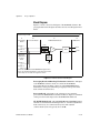
Prototyping Board and Benchtop Workstation Connectors—When the
NI ELVIS Prototyping Board is powered off, the CURRENT HI pin from
the prototyping board is disconnected; however, the NI ELVIS Benchtop
Workstation control panel connection is always connected.
DAQ Device—The DAQ device reads the reference sine wave on AI 5.
The AI 5 voltage reading is the input from the NI ELVIS to the DUT.
CURRENT LO
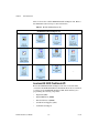
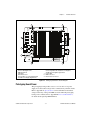
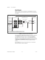
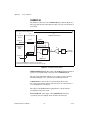
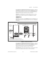
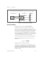
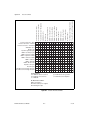
The hardware connection to the CURRENT LO pin is shown in Figure C-6.
The paragraphs that follow the figure describe each section of the figure in
more detail.
Impedance Analyzer Signal Path
A
B
C
D
Prototyping
Board
Protection Board
NI ELVIS Motherboard
DAQ Device
Gain
Gain
CURRENT LO
Gain
Benchtop
Workstation
Control
Panel
Fuse
Gain
Switch
AI 7
+
MUX
–
AI 15
CURRENT LO
Note: This CURRENT LO signal routes first to the
motherboard and then to the protection board as shown.
Figure C-6. CURRENT LO Block Diagram
Prototyping Board and Benchtop Workstation Connectors—When the
NI ELVIS Prototyping Board is powered off, the CURRENT LO pin from
the prototyping board is disconnected. The NI ELVIS Benchtop
Workstation control panel connection is always connected.
Protection Board—The signal from the DUT passes through a fuse on the
protection board. This fuse adds resistance to the measurement.
© National Instruments Corporation
C-9
NI ELVIS Hardware User Manual