1
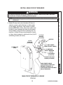
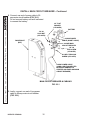
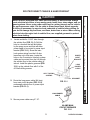
INSTALLATION INSTRUCTIONS FOR WHEELCHAIR LIFT MODEL NO. • WL7-vers. C • WL7-vers. C-1K DOT-Public Use Lift PATENTS PENDING FOR INSIDE VEHICLE INSTALLATION ONLY © MAXON Lift Corp. 2009 MP-06-09 REV. A APRIL 2009 PATENTS PENDING THIS PAGE INTENTIONALLY LEFT BLANK PATENTS PENDING TABLE OF CONTENTS INTRODUCTION ................................................................................................................... 6 SAFETY SUMMARY ............................................................................................................. 6 VEHICLE REQUIREMENTS ................................................................................................. 8 LIGHTING.............................................................................................................................. 9 WHEELCHAIR DOOR DIMENSIONS ................................................................................. 10 LIFT DIMENSIONS ..............................................................................................................11 LIFT COMPONENTS & TERMINOLOGY............................................................................ 14 DECALS AND DECAL PLACEMENT .................................................................................. 16 DECALS FOR WL7-vers. C................................................................................................. 17 DECALS FOR WL7-vers. C-1K ........................................................................................... 18 SERIAL PLATE & CONTROLLER ....................................................................................... 19 ANTI-SLIP & SAFETY STRIPING ....................................................................................... 20 LIFT INSTALLATION .......................................................................................................... 23 INSTALLATION KITS .......................................................................................................... 23 PREPARING AND POSITIONING THE LIFT ..................................................................... 23 USING TEMPLATE TO POSITION LIFT ............................................................................ 25 MOUNTING THE LIFT ........................................................................................................ 28 INSTALL MAIN CIRCUIT BREAKER................................................................................... 29 ROUTE/CONNECT CABLES & HAND PENDANT ............................................................. 31 CHECKING HYDRAULIC FLUID LEVEL ............................................................................ 39 ADJUSTMENTS.................................................................................................................. 42 MAT SWITCH ADJUSTMENT (IF REQUIRED)................................................................... 42 PLATFORM TILT ADJUSTMENT (MANDATORY) ............................................................. 44 INBOARD SWITCH ADJUSTMENT (IF REQUIRED) ......................................................... 46 CHANGING CONTROLLER TO SPANISH OR ENGLISH (IF REQUIRED) ....................... 48 FLOOR POSITION ADJUSTMENT (MANDATORY) .......................................................... 52 SYSTEM DIAGRAMS ......................................................................................................... 57 HYDRAULIC SYSTEM DIAGRAM ...................................................................................... 57 ELECTRICAL SYSTEM DIAGRAM ..................................................................................... 58 COMPLETED LIFT INSTALLATION CHECKLIST ............................................................. 59 5 PATENTS PENDING 11921 Slauson Ave. Santa Fe Springs, CA. 90670 (800) 227-4116 FAX (888) 771-7713 OUTBOARD ROLLSTOP TIME ADJUSTMENT (IF REQUIRED) ....................................... 50 INTRODUCTION This manual contains instructions for installing the MAXON MOBILITY Wheelchair Lift in a transit vehicle. Please follow these instructions carefully and call us immediately if you need assistance with the installation. Do not take shortcuts, skip over installation steps, or modify the Lift. Correct installation is important to ensure the Lift operates correctly. If you have questions that are not covered in this manual, please contact: MAXON Lift Corp. - Customer Service 11921 Slauson Ave., Santa Fe Springs, CA 90670 Phone: (800) 227-4116 FAX: (888) 771-7713 E-mail: [email protected] 11921 Slauson Ave. Santa Fe Springs, CA. 90670 (800) 227-4116 FAX (888) 771-7713 After receiving the Wheelchair Lift, unpack the Lift and check it for freight damage. For freight-damaged items, immediately submit a claim to the carrier. Make sure installation kit contains all items on the packing list shipped with the kit. Please report any missing items immediately to our Customer Service Department. The Warranty Registration Card, shipped with the Lift, must be completed and returned to Maxon Lift Corp. within 30 days after installation and/or receipt of the Lift. SAFETY SUMMARY Comply with the following WARNINGS and safety precautions while maintaining the Wheelchair Lift. See Operator’s Manual for operating safety requirements. ! WARNING 1. Read and understand the instructions in this Installation Manual before installing Lift. 2. Before operating the Lift, read and understand the operating instructions contained in the Operator’s Manual. 3. Comply with all WARNING and instruction decals attached to both the Lift and the vehicle. 4. Keep decals clean and legible. If decals are illegible or missing, free replacement decals are available from MAXON Lift Corp. Customer Service. Refer to DECALS & DECAL PLACEMENT and the instructions for installing decals on vehicle in this manual. 5. Consider the safety and location of bystanders and location of nearby objects when operating the Lift. Stand to one side of platform while operating the Lift. 6. Do not allow untrained persons to operate the Lift. 7. Do not stand, or allow obstructions, under the Platform when lowering the Lift. Be sure your feet are clear of the Lift. 8. Keep fingers, hands, arms, legs, and feet clear of moving Lift parts (and platform edges) when operating the Lift. 9. Make sure vehicle battery power is disconnected when installing Lift. Connect vehicle power to the Lift only when instructed to connect power. PATENTS PENDING 6 2. Before operating the Lift, read and understand the operating instructions contained in the Operator’s Manual. 3. Comply with all WARNING and instruction decals attached to both the Lift and the vehicle. 4. Keep decals clean and legible. If decals are illegible or missing, free replacement decals are available from MAXON Lift Corp. Customer Service. Refer to DECALS & DECAL PLACEMENT and the instructions for installing decals on vehicle in this manual. 5. Consider the safety and location of bystanders and location of nearby objects when operating the Lift. Stand to one side of platform while operating the Lift. 6. Do not allow untrained persons to operate the Lift. 7 PATENTS PENDING 11921 Slauson Ave. Santa Fe Springs, CA. 90670 (800) 227-4116 FAX (888) 771-7713 1. Read and understand the instructions in this Installation Manual before installing Lift. VEHICLE REQUIREMENTS 11921 Slauson Ave. Santa Fe Springs, CA. 90670 (800) 227-4116 FAX (888) 771-7713 The minimum vehicle requirements for installing the WL7 Wheelchair Lift are described below. Installing the Lift in accordance with the vehicle requirements and the instructions in this manual will result in an installation that is compliant with Federal Motor Vehicle Safety Standard (FMVSS) 403 and FMVSS 404. M F BODY STRENGTH ! WARNING FORCE & MOMENT PRODUCED BY LIFT ON VEHICLE FLOOR FIG. 8-1 Consult body manufacturer for body strength data. Make sure the forces created by the Lift are within the limits prescribed by body manufacturer. MODEL NOTE: The Lift represents approximately 400 lbs. of “F” shown in the illustration. The WL7 Lift must be bolted to the vehicle body. Body must withstand the maximum vertical force (“F”) and moment of force (“M”) (FIG. 8-1 and TABLE 8-1 ) produced by the Lift on the vehicle floor surface shown in FIGS. 8-2 and 8-3. “F” (LB) “M” (LB-IN) WL7-vers. C 2800 154,000 WL7-vers. C-1K 3400 187,000 TABLE 8-1 42.5” 15” LIFT FOOTPRINT ON VEHICLE FLOOR (LIFT WITH 33” OR 34” PLATFORM) FIG. 8-2 39.5” 15” LIFT FOOTPRINT ON VEHICLE FLOOR (LIFT WITH 30” PLATFORM) FIG. 8-3 PATENTS PENDING 8 11921 Slauson Ave. Santa Fe Springs, CA. 90670 (800) 227-4116 FAX (888) 771-7713 ELECTRICAL POWER Vehicle must have a 12 volt dc electrical system capable of supplying 65 amperes of electrical power to the Lift for each operating cycle. SAFETY INTERLOCK SYSTEM Vehicle must have an FMVSS 403 compliant, onboard Safety Interlock System that interfaces with the Wheelchair Lift interlock signal. Interlock signal may be V+ or V-. The interlock system on a host vehicle must: • • • Prevent the Lift from deploying when vehicle is in drive or reverse. Prevent the vehicle from moving when the Lift is deployed. Prevent the Lift from disabling vehicle if the Lift signals a deployed condition when the vehicle is moving. For the applicable interlock electrical connections on the Lift, refer to the ELECTRICAL SYSTEM DIAGRAM in this manual. For more information about the interlock connections, call: MAXON Lift Corp. Technical Service at (800) 227-4116 LIGHTING Public use vehicle manufacturers are responsible for complying with Lift lighting requirements stated in Federal Motor Vehicle Safety Standard No. 404, Platform Lift Installations in Motor Vehicles (49 CFR 571.404). 9 PATENTS PENDING VEHICLE REQUIREMENTS - Continued WHEELCHAIR DOOR DIMENSIONS A 11921 Slauson Ave. Santa Fe Springs, CA. 90670 (800) 227-4116 FAX (888) 771-7713 B WHEELCHAIR DOOR DIMENSIONS ON TYPICAL VEHICLE WITH SIDE DOOR (SEE TABLE 10-1) FIG. 10-1 A WHEELCHAIR WHEELCHAIR DOOR WIDTH DOOR HEIGHT MODEL DESCRIPTIONS (MINIMUM) 30” WIDE PLATFORM RH PUMP 30” WIDE PLATFORM LH PUMP 33” WIDE PLATFORM RH PUMP 33” WIDE PLATFORM LH PUMP 34” WIDE PLATFORM RH PUMP 34” WIDE PLATFORM LH PUMP 10 (MINIMUM) 39” 42” 43” TABLE 10-1 PATENTS PENDING B 56” LIFT DIMENSIONS D 13.3” 2.9” 1.4” 55.13” 0.5” 39” 25” E 4.75” 18-3/4” F FRONT VIEW OF STOWED LIFT (LH PUMP MODEL SHOWN) (SEE TABLE 11-1) FIG. 11-2 SIDE VIEW OF STOWED LIFT (LH PUMP MODEL SHOWN) FIG. 11-1 MODEL DESCRIPTIONS 30” WIDE PLATFORM RH PUMP 30” WIDE PLATFORM LH PUMP 33” WIDE PLATFORM RH PUMP 33” WIDE PLATFORM LH PUMP 34” WIDE PLATFORM RH PUMP 34” WIDE PLATFORM LH PUMP C D E F LIFT WIDTH AT WARNING BEACONS LIFT WIDTH AT HANDRAILS LIFT WIDTH AT BASE PLATE OVERALL LIFT WIDTH (INCLUDING PUMP COVER) 40.25” 38” 39.5” 45.5” 43.25” 41” 42.5” 48.5” 44.25” 42” 43.5” 49.5” TABLE 11-1 11 PATENTS PENDING 11921 Slauson Ave. Santa Fe Springs, CA. 90670 (800) 227-4116 FAX (888) 771-7713 C 18.9” VEHICLE REQUIREMENTS - Continued 11921 Slauson Ave. Santa Fe Springs, CA. 90670 (800) 227-4116 FAX (888) 771-7713 WHEELCHAIR DOOR 18-3/4” (APPROX.) 0.75” (MIN.) 48”(MAX.) WHEELCHAIR DOOR CLEARANCE & FLOOR HEIGHT ON TYPICAL VEHICLE WITH SIDE DOOR FIG. 12-1 PATENTS PENDING 12 6.75” (46” FLOOR LEVEL - REF) 8.75” (44” FLOOR LEVEL - REF) 10.25” (42” FLOOR LEVEL - REF) BASE PLATE OUTBOARD EDGE (REF) TYPICAL VEHICLE REAR BUMPER (VAN GND LVL) (BUS GND LVL) (BUS GND LVL) BODY CLEARANCE POINTS: 32”, 40”, 42”, 46” & 48” FLOOR HEIGHTS FIG. 13-1 13 PATENTS PENDING 11921 Slauson Ave. Santa Fe Springs, CA. 90670 (800) 227-4116 FAX (888) 771-7713 3.75” (48” FLOOR LEVEL - REF) LIFT COMPONENTS & TERMINOLOGY 10 INBOARD 6 RIGHT 4 11 10 6 11921 Slauson Ave. Santa Fe Springs, CA. 90670 (800) 227-4116 FAX (888) 771-7713 7 8 12 5 9 LEFT 1 12 3 LIFT COMPONENTS (SEE TABLE 13-1) FIG. 14-1 PATENTS PENDING 2 14 OUTBOARD 2. OUTBOARD ROLLSTOP 3. PLATFORM 4. HANDRAILS 5. INBOARD ROLLSTOP 6. HYDRAULIC CYLINDER 7. HYDRAULIC POWER UNIT (COVER IS SHOWN) LIFT CONTROLLER (BRAIN BOX) 8. 9. BASE 10. THRESHOLD WARNING BEACON 11. THRESHOLD WARNING ALARM 12. PLATFORM LIGHTS DESCRIPTION Component that bridges the entry way, through the Lift, into the vehicle. Detects if that portion of Lift is occupied during “UP/DOWN” operation between vehicle floor and the ground. Barrier to prevent the wheelchair from rolling off of the platform. Provides entry/exit ramp for platform on the ground. Contains the wheelchair and occupant during “UP/ DOWN” operation between vehicle floor and the ground. (Left/Right) Provides a hand hold for the Lift occupant. Barrier to prevent the wheelchair from rolling off inboard side of platform. Provides bridge between platform and threshold. (Left/Right) Telescoping steel tube and rod, pressurized by hydraulic fluid, that folds and unfolds the Lift and moves the Lift up and down. Contains motorized hydraulic pump, manually operated backup pump, fluid lines, and controls that operate the hydraulic cylinders. Electronic device that controls and monitors Lift operation and the interlock connection with the vehicle. Structure that secures Lift to the vehicle floor. Flashing red light indicates threshold is occupied by a person or object when the platform is below floor level. Indicates outboard rollstop is open if platform is at floor level. Audible alarm sounds when threshold is occupied by a person or object when the platform is below floor level. Also indicates outboard rollstop is open if platform is at floor level. Illuminates the platform when ready to load at floor level and during “UP/DOWN” operation between vehicle floor and the ground. TABLE 15-1 15 PATENTS PENDING 11921 Slauson Ave. Santa Fe Springs, CA. 90670 (800) 227-4116 FAX (888) 771-7713 ITEM NAME 1. THRESHOLD PLATE DECALS AND DECAL PLACEMENT DECAL ”D” DECAL “O” DECAL “K” DECAL “A” DECAL “B” 11921 Slauson Ave. Santa Fe Springs, CA. 90670 (800) 227-4116 FAX (888) 771-7713 DECAL “F” DECAL “L” DECAL “M” DECAL “I” DECAL“J” DECAL“N” DECAL “C” DECAL “E” DECAL“N” DECAL “H” FIG. 16-1 All WARNING, CAUTION, and OPERATION decals provided with Wheelchair Lift must always be in place on the Lift and vehicle (see FIG. 36-1), and must always be legible. If decals are missing or illegible, get free replacement decals from: MAXON Lift Corp. - Customer Service 11921 Slauson Ave., Santa Fe Springs, CA 90670 Phone: (800) 227-4116 FAX: (888) 771-7713 E-mail: [email protected] PATENTS PENDING 16 11921 Slauson Ave. Santa Fe Springs, CA. 90670 (800) 227-4116 FAX (888) 771-7713 DECALS FOR WL7-vers. C DECAL SET P/N 268302-01 FIG. 17-1 17 PATENTS PENDING DECALS AND DECAL PLACEMENT - Continued DECALS FOR WL7-vers. C-1K 11921 Slauson Ave. Santa Fe Springs, CA. 90670 (800) 227-4116 FAX (888) 771-7713 DECAL SET P/N 268302-03 FIG. 18-1 PATENTS PENDING 18 11921 Slauson Ave. Santa Fe Springs, CA. 90670 (800) 227-4116 FAX (888) 771-7713 SERIAL PLATE & CONTROLLER CONTROLLER OVERLAY P/N 2667630-01 FIG. 19-1 SERIAL PLATE P/N 905246-8 FIG. 19-2 19 PATENTS PENDING ANTI-SLIP & SAFETY STRIPING (30” WIDE PLATFORM) YELLOW TAPE (BOTTOM-ROLLSTOP) P/N 905293-17 11921 Slauson Ave. Santa Fe Springs, CA. 90670 (800) 227-4116 FAX (888) 771-7713 ANTI-SLIP TAPE (ROLLSTOP) P/N 096020-13 ANTI-SLIP TAPE P/N 096024-10 ANTI-SLIP TAPE P/N 096020-10 ANTI-SLIP TAPE P/N 096013-10 YELLOW TAPE (OUTBOARD) P/N 905293-11 YELLOW TAPE (OUTBOARD) P/N 905293-14 ANTI-SLIP TAPE (ROLLSTOP) P/N 096020-13 YELLOW TAPE P/N 905293-11 YELLOW TAPE (INBOARD) P/N 905293-16 YELLOW TAPE P/N 905293-14 FIG. 20-1 PATENTS PENDING 20 YELLOW TAPE (INBOARD & OUTBOARD) P/N 905293-13 ANTI-SLIP & SAFETY STRIPING - Continued YELLOW TAPE (BOTTOM-ROLLSTOP) P/N 905293-18 ANTI-SLIP TAPE (ROLLSTOP) P/N 096020-14 ANTI-SLIP TAPE P/N 096024-11 ANTI-SLIP TAPE P/N 096020-11 ANTI-SLIP TAPE P/N 096013-11 YELLOW TAPE (OUTBOARD) P/N 905293-11 YELLOW TAPE (OUTBOARD) P/N 905293-14 ANTI-SLIP TAPE (ROLLSTOP) P/N 096020-14 YELLOW TAPE P/N 905293-11 YELLOW TAPE (INBOARD) P/N 905293-16 YELLOW TAPE P/N 905293-14 YELLOW TAPE (INBOARD & OUTBOARD) P/N 905293-15 FIG. 21-1 21 PATENTS PENDING 11921 Slauson Ave. Santa Fe Springs, CA. 90670 (800) 227-4116 FAX (888) 771-7713 (33” WIDE PLATFORM) ANTI-SLIP & SAFETY STRIPING - Continued (34” WIDE PLATFORM) 11921 Slauson Ave. Santa Fe Springs, CA. 90670 (800) 227-4116 FAX (888) 771-7713 YELLOW TAPE (BOTTOM-ROLLSTOP) P/N 905293-18 ANTI-SLIP TAPE (ROLLSTOP) P/N 096020-15 ANTI-SLIP TAPE P/N 096024-12 ANTI-SLIP TAPE P/N 096020-12 ANTI-SLIP TAPE P/N 096013-11 YELLOW TAPE (OUTBOARD) P/N 905293-11 YELLOW TAPE (OUTBOARD) P/N 905293-14 ANTI-SLIP TAPE (ROLLSTOP) P/N 096020-15 YELLOW TAPE P/N 905293-11 YELLOW TAPE (INBOARD) P/N 905293-16 YELLOW TAPE P/N 905293-14 FIG. 22-1 PATENTS PENDING 22 YELLOW TAPE (INBOARD & OUTBOARD) P/N 905293-15 LIFT INSTALLATION An installation kit is required to install Lift on your vehicle. Refer to the instruction sheet, included with the installation kit, for specific instructions to fit the Lift to your vehicle. PREPARING AND POSITIONING THE LIFT 1. Make sure you have the correct model of Lift. NOTE: Keep shipping straps on Lift until Lift is bolted to vehicle and power is connected. 2. Unpack the Lift and check for damage. Report damage to: MAXON Lift Corp. - Customer Service 11921 Slauson Ave., Santa Fe Springs, CA 90670 Phone: (800) 227-4116 FAX: (888) 771-7713 E-mail: [email protected] WHEELCHAIR DOORWAY DOOR 3. Open the wheelchair door on vehicle (FIG. 23-1) in which Lift will be mounted. Secure door wide open. VEHICLE RH SIDE VIEW FIG. 23-1 4. Check the clearance dimensions of your vehicle before beginning installation. Refer to VEHICLE REQUIREMENTS section in this Installation Manual. 23 PATENTS PENDING 11921 Slauson Ave. Santa Fe Springs, CA. 90670 (800) 227-4116 FAX (888) 771-7713 INSTALLATION KITS PREPARING AND POSITIONING THE LIFT - Continued NOTE: You may use a template instead of the Lift for positioning the Lift on vehicle. To use a template, refer to USING TEM PLATE TO POSITION LIFT section in this Installation Manual. 11921 Slauson Ave. Santa Fe Springs, CA. 90670 (800) 227-4116 FAX (888) 771-7713 5. Using an appropriate lifting device that can safely lift 500 pounds, raise Lift to the wheelchair doorway. Place the Lift inside doorway (FIG. 24-1). Align outboard edge of Lift threshold plate parallel with outboard edge of doorway. The decal on DECAL (FACES the underside of the Lift platform must OUTBOARD) face outboard (FIG. 24-1). 6. Position the Lift according to the clearance dimensions given in VEHICLE REQUIREMENTS section in this Installation Manual. 7. Remove lifting device and close wheelchair door. Enter the vehicle. Verify the wheelchair door closes correctly and the minimum clearance is 3/4”. If door will not close correctly, reposition the Lift. 8. Secure vehicle door wide open (FIG. 24-1). 9. Check under the vehicle floor for possible interference between the Lift base plate mounting bolts and the vehicle underbody. For example, check subframe members, wiring harnesses, cables, and fluid lines. PATENTS PENDING 24 WHEELCHAIR LIFT DOOR VEHICLE RH SIDE VIEW FIG. 24-1 1. Fabricate template for base plate hole pattern according to the dimensions shown in FIGS. 25-1, 25-2, 26-1 and 26-2. Use a suitable material that maintains correct shape and dimensions. BASE PLATE HOLE PATTERN FOR LIFTS WITH 33” & 34” WIDE PLATFORMS & RH PUMP FIG. 25-1 BASE PLATE HOLE PATTERN FOR LIFTS WITH 33” & 34” WIDE PLATFORMS & LH PUMP FIG. 25-2 25 PATENTS PENDING 11921 Slauson Ave. Santa Fe Springs, CA. 90670 (800) 227-4116 FAX (888) 771-7713 USING TEMPLATE TO POSITION LIFT USING TEMPLATE TO POSITION LIFT - Continued 11921 Slauson Ave. Santa Fe Springs, CA. 90670 (800) 227-4116 FAX (888) 771-7713 BASE PLATE HOLE PATTERN FOR LIFTS WITH 30” WIDE PLATFORM & LH PUMP FIG. 26-1 BASE PLATE HOLE PATTERN FOR LIFTS WITH 30” WIDE PLATFORM & RH PUMP FIG. 26-2 PATENTS PENDING 26 For vehicles with 48” floor height: If the front edge of Lift base plate is moved more than 3.75” (5” from outside of body, as shown in FIG. 11-1) away from the inside of the wheelchair door, lower Lift arms can hit vehicle body before platform reaches the ground. See the vehicle floor levels plotted in FIG. 11-1 and maintain the clearance for the floor level that applies to your Lift installation. 2. Center the template inside wheelchair doorway (FIG. 27-1). Line up the outboard edge of template parallel with inboard edge of doorway. Maintain center and the clearance dimension shown. VEHICLE BODY (CUTAWAY) BASE PLATE TEMPLATE HOLE PATTERN BACK 1 2 9 3 4 5 6 10 7 8 INSIDE OF DOOR 3.75” FRONT CENTER BASE PLATE TEMPLATE CLEARANCE FROM WHEELCHAIR DOOR (TOP VIEW, SIDE DOOR SHOWN) FIG. 27-1 27 PATENTS PENDING 11921 Slauson Ave. Santa Fe Springs, CA. 90670 (800) 227-4116 FAX (888) 771-7713 CAUTION MOUNTING THE LIFT NOTE: MAXON recommends using all 10 carriage screws (Kit items) to bolt Lift to vehicle. A minimum of 8 screws or bolts and use of holes 1, 2, 3, 4 & 9 are required for correct installation. Also, the 3 front holes should be selected to give a symmetrical bolt pattern (i.e. holes 5,10, & 8 or holes 6,10, & 7). 11921 Slauson Ave. Santa Fe Springs, CA. 90670 (800) 227-4116 FAX (888) 771-7713 1. Use template (FIG. 27-1) or the base plate on the Lift (FIG. 28-1, holes 1-10) to mark eight (8) to ten (10) 7/16” mounting holes through the vehicle floor. Before drilling holes in the vehicle floor, make sure no wires and fluid lines are too close to hole locations. Drill holes 1, 2, 9, 3, and 4. BACK 1 2 5 6 9 3 4 10 7 8 FRONT BASE PLATE BOLT HOLE PATTERN FIG. 28-1 NOTE: Vehicle floor must meet the requirements shown at the beginning of the VEHICLE REQUIREMENTS section in this Installation Manual. 2. Position Lift so holes 1-10 in the base plate (FIG. 28-1) are aligned with the correct holes drilled in vehicle floor. 3. Temporarily secure Lift to vehicle with two mounting bolts (Kit items), inserted through base plate holes 1 and 4, or holes 2 and 3 (FIG. 28-1). Use two lock nuts and correct under-vehicle supports (Kit items) to secure the Lift. Use instructions supplied with vehicle installation kit to select the correct bolts, nuts and supports. Alternately, tighten the two bolts and nuts to 20 to 30 LBS.-FT. PATENTS PENDING 28 ! WARNING To prevent personal injury and equipment damage, make sure power is disconnected from Lift when installing electrical parts. NOTE: Apply dielectric grease on all electrical connections after all electrical cables are connected. 1. Attach 90 amp main circuit breaker (Kit item) to vehicle so power cable (Kit item) is within reach of the battery, as follows. Find a place to attach bracket (FIG. 29-1). (Note: The power cable must be able to reach between 90 amp circuit breaker and (+) battery terminal without straining the connections.) Attach 90 amp circuit breaker to bracket. Next, attach bracket to vehicle with four (4) #12 self-drilling screws (Kit items). 1/4” FLAT WASHER (2 PLACES) BATTERY 1/4”-20 LOCK NUT (2 PLACES) 2 AWG POWER CABLE (SHORT CABLE) POWER UNIT (REF) 90 AMP MAIN CIRCUIT BREAKER 1/4”-20 CAP SCREW (2 PLACES) #12 SELF-DRILLING SCREW (4 PLACES) 2 AWG POWER CABLE (LONG CABLE CONNECTED BETWEEN TERMINAL OF STARTER SOLENOID AND MAIN CIRCUIT BREAKER) MAIN CIRCUIT BREAKER & CABLING FIG. 29-1 29 PATENTS PENDING 11921 Slauson Ave. Santa Fe Springs, CA. 90670 (800) 227-4116 FAX (888) 771-7713 INSTALL MAIN CIRCUIT BREAKER INSTALL MAIN CIRCUIT BREAKER - Continued 2. Connect one end of power cable to 90 amp main circuit breaker (FIG. 30-1). Do not connect battery end until instructed to connect the battery. 1/4” FLAT WASHER (2 PLACES) BATTERY 11921 Slauson Ave. Santa Fe Springs, CA. 90670 (800) 227-4116 FAX (888) 771-7713 1/4”-20 LOCK NUT (2 PLACES) 2 AWG POWER CABLE (SHORT CABLE) POWER UNIT (REF) 90 AMP MAIN CIRCUIT BREAKER 1/4”-20 CAP SCREW (2 PLACES) #12 SELF-DRILLING SCREW (4 PLACES) 2 AWG POWER CABLE (LONG CABLE CONNECTED BETWEEN TERMINAL OF STARTER SOLENOID AND MAIN CIRCUIT BREAKER) MAIN CIRCUIT BREAKER & CABLING FIG. 30-1 3. Lastly, connect one end of long power cable to 90 amp main circuit breaker (FIG. 30-1). PATENTS PENDING 30 ! CAUTION Never route an energized wire. Make sure the battery is disconnected. Always route electrical wire clear of any moving parts, brake lines, sharp edges, and exhaust systems. Never route power cable next to a wiring harness on the vehicle. Do not loop excess cable. Cut the cable to fit and leave slack. Attach securely. If drilling is necessary, be sure to check underside of vehicle before drilling so you do not damage any fuel lines, vent lines, brake lines or wires. When routing electrical wire through a hole in vehicle floor, use supplied grommet to protect wires from chafing. 1. Locate and drill a 1-5/16” hole through the vehicle floor (FIG. 31-1). Drill the hole in a location that will be hidden by the pump cover and that will allow power cable to be routed to power input bracket (FIG. 31-1). Since the interlock system wiring from the Lift also branches out in that area, locate the hole so the 3-conductor Interlock system cable can be routed from the Lift through the vehicle floor to the vehicle safety interlock. Install the plastic grommet (FIG. 31-1) on the vehicle floor with 2 of the #12 self-drilling screws. POWER INPUT BRACKET LONG POWER CABLE SELF-TAPPING SCREWS GROMMET 2. Route the long power cable (Kit item) from main circuit breaker (FIG. 31-2), underneath vehicle floor to power input bracket (FIG. 31-1). FIG. 31-1 LONG POWER CABLE 3. Secure power cable every 8”-10”. 90 AMP MAIN CIRCUIT BREAKER FIG. 31-2 31 PATENTS PENDING 11921 Slauson Ave. Santa Fe Springs, CA. 90670 (800) 227-4116 FAX (888) 771-7713 ROUTE/CONNECT CABLES & HAND PENDANT ROUTE/CONNECT CABLES & HAND PENDANT - Continued POWER INPUT BRACKET 11921 Slauson Ave. Santa Fe Springs, CA. 90670 (800) 227-4116 FAX (888) 771-7713 4. Cut any excess wire from long power cable. Strip 1/2” insulation from the cut end and install 2 GA terminal lug and shrink tubing. Next, insert the power cable through the protective cover (FIG. 32-1). Connect the TERMINAL cable terminal to the terminal stud on the STUD power input bracket as shown in FIG. 321. Position the protective cover over the power cable connection (FIG. 32-1). 2 GA TERMINAL LUG EXTERNAL TOOTH LOCK WASHER HEX NUT LONG POWER CABLE PROTECTIVE COVER FIG. 32-1 5. Route the interlock cable from safety interlock system on the vehicle, underneath vehicle floor and through the grommet, and up to the Lift (FIG. 32-2). If possible, use the same cable routing as the long power cable installed in previous steps. Secure the interlock cable every 8”-10”. INTERLOCK CABLE 6. Make sure interlock cable will reach the white-red stripe wire (interlock signal from vehicle) and the brown wire (interlock signal to vehicle) on the Lift (FIG. 32-2). Signal may be ground or V+. Connect the interlock wires from the vehicle interlock system to the white-red stripe wire and brown wire on the Lift (FIG. 32-2). INTERLOCK WIRE (SIGNAL FROM VEHICLE) INTERLOCK WIRE (SIGNAL TO VEHICLE) BROWN WIRE (FROM LIFT) WHITE-RED STRIPE WIRE (FROM LIFT) FIG. 32-2 PATENTS PENDING 32 GROUND CABLE GROMMET NOTE: Clean the ground cable connection point on the frame down to bare metal. NOTE: If there is a grounding point on the frame, use it to connect ground cable. Skip step 8. NOTE: Apply dielectric grease to all electrical connections. GROUND CABLE ROUTED FROM LIFT FIG. 33-1A BARE METAL TERMINAL LUG 3/8”-16 X 1” LG. CAP SCREW VEHICLE FRAME 8. Extend the ground cable to reach vehicle frame (FIG. 33-2). Connect to an existing grounding point if available. If necessary, drill a 13/32” (0.406”) hole in vehicle frame for bolting the ground cable terminal lug (FIG. 33-2). GROUND 3/8”-16 HEX NUT CABLE 9. Bolt the ground cable terminal lug to vehicle frame as shown in FIG. 33-2. 3/8” LOCK WASHER BOLTING GROUND CABLE TO VEHICLE FRAME FIG. 33-2 33 PATENTS PENDING 11921 Slauson Ave. Santa Fe Springs, CA. 90670 (800) 227-4116 FAX (888) 771-7713 7. Uncoil the ground cable from the bottom of the pump cover. Route the ground cable on the Lift through grommet in vehicle floor (FIG. 33-1A & 33-1B). ROUTE/CONNECT CABLES & HAND PENDANT - Continued ! CAUTION To prevent vehicle access door from pinching and damaging the hand pendant cable, secure cable away from the door frame. Also, be sure that the hand pendant cable does not interfere with or bind against moving parts. 11921 Slauson Ave. Santa Fe Springs, CA. 90670 (800) 227-4116 FAX (888) 771-7713 10. Connect the hand pendant cable as follows. Feed the cable through the hole located in the main frame (FIG. 34-1). Secure cable strain relief to main frame with plastic nut (FIG. 34-1). Next, connect hand pendant connector to wiring harness (FIG. 34-1). WIRING HARNESS CONNECTOR MAIN FRAME HEX NUT CONNECTOR STRAIN RELIEF HAND PENDANT CONNECTING HAND PENDANT CABLE (RH SIDE CONNECTION SHOWN) FIG. 34-1 PATENTS PENDING 34 HAND PENDANT & HANGER CABLE HOOK PUMP COVER TYPICAL LOCATION (INSIDE VEHICLE) FOR STOWING HAND PENDANT FIG. 35-1 35 PATENTS PENDING 11921 Slauson Ave. Santa Fe Springs, CA. 90670 (800) 227-4116 FAX (888) 771-7713 11. Find accessible place on vehicle wall or wheelchair door (near Lift) to place the hand pendant hanger and cable hook (FIG. 35-1). ROUTE/CONNECT CABLES & HAND PENDANT - Continued 12. Place decals (from Parts Box) on the vehicle, near the hand pendant (typical placement shown in FIG. 36-1). Make sure decals are visible to operator when Lift is being operated. HAND PENDANT & HANGER MOUNTING DECAL “J” DECAL “I” 11921 Slauson Ave. Santa Fe Springs, CA. 90670 (800) 227-4116 FAX (888) 771-7713 DECAL “A” DECAL “C” DOOR DECAL “B” CABLE HOOK DECAL “A” P/N 268303-01 DECALS AND HAND PENDANT MOUNTING ON VEHICLE FIG. 36-1 DECAL SET FOR WL7-vers.C-1K P/N 267620-04 FIG. 36-3 DECAL SET FOR WL7-vers.C P/N 267620-02 FIG. 36-2 PATENTS PENDING 36 POSITIVE (+) BATTERY TERMINAL SHORT POWER CABLE BOLT NUT CONNECTING POWER TO LIFT (TYPICAL) FIG. 37-1 POWER ON/OFF SWITCH 14. Turn ON power ON/OFF switch on pump cover to power the Lift (FIG. 37-2). The POWER light on hand pendant should be illuminated (FIG. 37-3). Briefly press the FOLD button on hand pendant (FIG. 37-3) to pressurize hydraulic system. Then, remove remaining shipping straps. STOWED LIFT - LH SIDE SHOWN FIG. 37-2 UP FOLD FOLD UNFOLD POWER LIGHT HAND PENDANT FIG. 37-3 37 PATENTS PENDING 11921 Slauson Ave. Santa Fe Springs, CA. 90670 (800) 227-4116 FAX (888) 771-7713 13. Connect short power cable to vehicle battery as follows. Remove nut from positive (+) battery terminal connector (FIG. 37-1). Connect the power cable. Reinstall nut. ROUTE/CONNECT CABLES & HAND PENDANT - Continued 15. Press the UNFOLD button on hand pendant to unfold Lift (FIG. 381). Platform lights will turn on when platform is at floor level. PLATFORM LIGHT (2 PLACES) 11921 Slauson Ave. Santa Fe Springs, CA. 90670 (800) 227-4116 FAX (888) 771-7713 LIFT AT FLOOR LEVEL FIG. 38-1 16. Next, press DOWN button on hand pendant. When the platform reaches the ground, the outboard rollstop will automatically open to ramp position (FIG. 38-2). OUTBOARD ROLLSTOP PLATFORM GROUND PLATFORM LOWERED TO GROUND LEVEL FIG. 38-2 17. Install the remaining bolts, lock nuts, and under-vehicle supports supplied with your installation kit. Use the instruction sheet (Kit item) for information to install the remaining Kit items correctly. NOTE: Lift installation is not complete until all the instructions in this manual, your installation kit instructions, and the checks and adjustments that follow (in this manual) are completed. PATENTS PENDING 38 CHECKING HYDRAULIC FLUID LEVEL Keep dirt, water and other contaminants from entering the hydraulic system. Before opening the hydraulic fluid reservoir filler cap, drain plug and hydraulic lines, wipe off contaminants that can get in the openings. Also, protect the openings from accidental contamination. 1. Check the hydraulic fluid level in reservoir as follows. With Lift in STOWED position, fluid level should be as shown in FIG. 39-1. PUMP COVER INSPECTION SLOT RESERVOIR 2” HYDRAULIC FLUID LEVEL (LH PUMP SHOWN) FIG. 39-1 2. If needed, add fluid to the reservoir as follows. Unbolt the pump cover as shown in FIG. 39-2. PUMP COVER SCREWS UNBOLTING/BOLTING PUMP COVER (LH PUMP SHOWN) FIG. 39-2 39 PATENTS PENDING 11921 Slauson Ave. Santa Fe Springs, CA. 90670 (800) 227-4116 FAX (888) 771-7713 ! CAUTION CHECKING HYDRAULIC FLUID LEVEL - Continued 3. Pull out filler cap (FIG. 40-1). Fill the reservoir with hydraulic fluid (TABLE 40-1) to level shown in FIG. 40-1. Reinstall filler cap (FIG. 40-1). 11921 Slauson Ave. Santa Fe Springs, CA. 90670 (800) 227-4116 FAX (888) 771-7713 RECOMMENDED HYDRAULIC FLUID BRAND PART NUMBER ROSEMEAD THS FLUID 17111 EXXON UNIVIS HVI 26 FILLER CAP RESERVOIR TABLE 40-1 2” NOTE: If the expected seasonal temperatures are below 20°F, use MIL-H-5606G hydraulic fluid. HYDRAULIC FLUID LEVEL (LH PUMP SHOWN) FIG. 40-1 4. Bolt on the pump cover as shown in FIG. 39-2. Tighten the 5/16”-18 cover screws until snug. PATENTS PENDING 40 41 11921 Slauson Ave. Santa Fe Springs, CA. 90670 (800) 227-4116 FAX (888) 771-7713 THIS PAGE INTENTIONALLY LEFT BLANK PATENTS PENDING ADJUSTMENTS MAT SWITCH ADJUSTMENT (IF REQUIRED) 1. Make sure power switch (FIG. 42-1A) is turned on. Lower Lift to the ground (FIG. 421A). POWER SWITCH 11921 Slauson Ave. Santa Fe Springs, CA. 90670 (800) 227-4116 FAX (888) 771-7713 5/8” HEIGHT MEASUREMENT (RH SIDE SHOWN) FIG. 42-1B LIFT AT GROUND LEVEL FIG. 42-1A 2. Measure the height of the threshold plate as shown in FIG. 42-1B. If the height is 5/8”, go to step 4 (skip step 3). If the height is not 5/8”, go to step 3. LIFT THRESHOLD FIG. 42-2A 3. Set edge of the threshold plate to 5/8” height by turning the adjustment screw on the RH side of threshold plate (FIG. 42-2B). Turn adjustment screw counterclockwise (FIG. 42-3) to raise threshold plate or clockwise to lower. Repeat for LH side of threshold plate. Alternately measure height (see instruction 2). Then, turn the adjustment screw on RH side and LH side until the entire edge of threshold plate is at 5/8” height. ADJUSTMENT SCREW HEIGHT ADJUSTMENT SCREW (RH SIDE SHOWN) FIG. 42-2B CCW - RAISE CW - LOWER HEIGHT ADJUSTMENT SCREWS FIG. 42-3 PATENTS PENDING 42 THRESHOLD WARNING BEACON THRESHOLD WARNING ALARM BASE PLATE ADJUSTMENT SCREW THRESHOLD PLATE ADJUSTING SWITCH FIG. 43-1B LH SIDE OF LIFT FIG. 43-1A CW - UNTIL ALARM & BEACONS TURN ON 1-1/2 TURN CCW - ALARM & BEACONS TURN OFF MAT SWITCH ADJUSTMENT SCREWS FIG. 43-2 5. Step on threshold plate. Warning alarm and beacons should activate. If the warning alarm and beacons do not activate, slightly turn adjustment screw (FIGS. 43-1B and 43-2) clockwise. Repeat until warning alarm and beacons activate when stepping on threshold plate and deactivate stepping off threshold plate. 43 PATENTS PENDING 11921 Slauson Ave. Santa Fe Springs, CA. 90670 (800) 227-4116 FAX (888) 771-7713 4. Turn the MAT switch adjustment screw (FIGS. 43-1B and 43-2) clockwise until threshold warning alarm and beacons activate (FIG. 43-1A). Then, turn adjustment screw counter-clockwise (FIG. 43-2) approximately 1-1/2 turn. Warning alarm and beacons should turn off. PLATFORM TILT ADJUSTMENT (MANDATORY) NOTE: The platform tilt adjustment is important for operation of the outboard rollstop and for keeping platform level when it reaches the ground. Vehicle floor height, Lift and stiffness of the vehicle suspension may change the angle of platform on the ground. 11921 Slauson Ave. Santa Fe Springs, CA. 90670 (800) 227-4116 FAX (888) 771-7713 1. Make sure power switch (FIG. 44-1) is turned on. Lower the platform and stop approximately 4” above ground. POWER SWITCH GROUND LEVEL PLATFORM 4” PLATFORM LOWERED TO GROUND LEVEL FIG. 44-1 2. Measure distance from front of the platform (1) to the ground (FIG. 44-2). Next, measure the distance from the bottom of the vertical arm (2) to the ground (FIG. 44-2). POWER SWITCH VERTICAL ARM GROUND LEVEL (1) 3. The measurement at the vertical arm (2) must be 1/2” -1” more than the measurement at the front of platform (1). For example: If you measure 4” at the front (1), then you should measure from 4-1/2” to 5” at the vertical arm (2). If there is not a 1/2” - 1” difference, go to step 4 to obtain the correct measurement. PATENTS PENDING PLATFORM (2) PLATFORM LOWERED TO GROUND LEVEL FIG. 44-2 44 CW - PLATFORM TILT UP CCW - PLATFORM TILT DOWN PLATFORM TILT ADJUSTMENT SCREWS FIG. 45-2 45 PATENTS PENDING 11921 Slauson Ave. Santa Fe Springs, CA. 90670 (800) 227-4116 FAX (888) 771-7713 OUTBOARD ROLLSTOP 4. Manually lower the inboard ADJUSTMENT (REF) rollstop for access to the adSCREW justment screws (FIG. 45-1). To ensure proper leveling, turn platform tilt adjustment screws (FIG. 45-1) an equal amount on both sides of platform. Turn adjustment screws clockwise (FIG. 45-2) to tilt the platform up or counter-clockwise to tilt INBOARD ROLLSTOP PLATFORM platform down. PLATFORM TILT ADJUSTMENT SCREW (BACK VIEW OF PLATFORM SHOWN) FIG. 45-1 INBOARD SWITCH ADJUSTMENT (IF REQUIRED) NOTE: Do this procedure if the Controller reads “IBRS SW” when Inboard Rollstop is locked in the up position. The adjustment is done correctly if the Controller does not read “IBRS SW” when the Inboard Rollstop is locked in the up position. POWER SWITCH 11921 Slauson Ave. Santa Fe Springs, CA. 90670 (800) 227-4116 FAX (888) 771-7713 1. Position the platform at floor level (FIG. 46-1). PLATFORM AT FLOOR LEVEL (LH SIDE SHOWN) FIG. 46-1 2. Turn OFF power switch on pump cover (FIG. 46-1). 3. Using the manual backup pump (FIG. 462), lower the platform until inboard rollstop (IBRS) is locked in the up position (FIG. 471). Refer to Operation Manual for instructions to operate the manual pump. RELEASE VALVE BACKUP PUMP HANDLE USING BACKUP PUMP TO UNFOLD (LIFT WITH LH PUMP) FIG. 46-2 PATENTS PENDING 46 IBRS PUSH IBRS AGAINST LOCK PLATFORM BELOW FLOOR LEVEL, WITH IBRS UP (LH SIDE SHOWN) FIG. 47-1 5. On the inboard rollstop switch, loosen screws (1) and (2) one-half turn (FIG. 47-2B). Next, rotate switch bracket clockwise until the switch activates with an audible “click”. Then tighten screws (1) and (2) securely. SCREW (2) SCREW (1) SWITCH (REF) SWITCH BRACKET POWER SWITCH 6. Turn ON power switch on pump cover (FIG. 47-2A). Then raise (UP) the platform to floor level (FIG. 46-1). Verify that “INBD SW” is not displayed on the lift controller. If necessary repeat this procedure. CUT-AWAY VIEW OF LH VERTICAL ARM & IBRS SWITCH FIG. 47-2B PLATFORM BELOW FLOOR LEVEL, WITH IBRS UP (LH SIDE SHOWN) FIG. 47-2A 47 PATENTS PENDING 11921 Slauson Ave. Santa Fe Springs, CA. 90670 (800) 227-4116 FAX (888) 771-7713 4. Push the inboard rollstop back against the lock as if a wheelchair is pushing on the rollstop FIG. 47-1). CHANGING CONTROLLER TO SPANISH OR ENGLISH (IF REQUIRED) NOTE: The power switch on the Lift must be turned OFF before entering SETUP. UP FOLD 1. Turn power switch OFF (FIG. 48-2). 11921 Slauson Ave. Santa Fe Springs, CA. 90670 (800) 227-4116 FAX (888) 771-7713 HAND PENDANT: ENTERING SETUP FIG. 48-1 POWER SWITCH CONTROLLER (REF) 2. Enter SETUP by holding both the UP and FOLD switches on the hand pendant (FIG. 48-1) and turning the power switch ON at the same time (FIG. 48-2). Controller will read SETUP (FIG. 48-3). TURNING POWER SWITCH ON/OFF (LH PUMP SHOWN) FIG. 48-2 SETUP CONTROLLER: ENTERING SETUP FIG. 48-3 PATENTS PENDING 48 FOLD HAND PENDANT: CHANGING SETUP MODE FIG. 49-1 LANGUAGE: ENGLISH CONTROLLER: LANGUAGE SETTING (ENGLISH OR SPANISH) FIG. 49-2 NOTE: After you exit SETUP, the controller readings will be displayed in the language you selected. 4. Push the UP switch or DOWN switch to change from ENGLISH to SPANISH (or from SPANISH to ENGLISH) (FIGS. 49-2 and 49-3). UP DOWN HAND PENDANT: CHANGING THE SETTING FIG. 49-3 5. Push and release the FOLD switch (FIG. 49-1) three times to exit SETUP (FIG. 49-4). MAXON LIFT CORP. CONTROLLER: EXITING SETUP FIG. 49-4 49 PATENTS PENDING 11921 Slauson Ave. Santa Fe Springs, CA. 90670 (800) 227-4116 FAX (888) 771-7713 3. Push and release the FOLD switch (FIG. 49-1). Controller should be in the LANGUAGE mode (FIG. 49-2). OUTBOARD ROLLSTOP TIME ADJUSTMENT (IF REQUIRED) NOTE: Call MAXON Technical Service before doing this adjustment. UP FOLD NOTE: The power switch on the Lift must be turned OFF before entering SETUP. 11921 Slauson Ave. Santa Fe Springs, CA. 90670 (800) 227-4116 FAX (888) 771-7713 1. Turn power switch OFF (FIG. 50-2). HAND PENDANT: ENTERING SETUP FIG. 50-1 POWER SWITCH CONTROLLER (REF) 2. Enter SETUP by holding both the UP and FOLD switches on the hand pendant (FIG. 50-1) and turning the power switch ON at the same time (FIG. 50-2). Controller will read SETUP (FIG. 50-3). TURNING POWER SWITCH ON/OFF (LH PUMP SHOWN) FIG. 50-2 SETUP CONTROLLER: ENTERING SETUP FIG. 50-3 PATENTS PENDING 50 FOLD HAND PENDANT: CHANGING SETUP MODE FIG. 51-1 NOTE: A larger number for the OUTBD TIME setting allows more time for the controller to sense the outboard rollstop is closed. A smaller number decreases the time. Call MAXON Technical Service to advise you about the best setting for your vehicle. OUTBD TIME: 0 CONTROLLER: SETTING OUTBOARD RAMP TIME (RANGE IS -7 TO 10) FIG. 51-2 4. Push the UP switch (FIG. 51-3) to increase the OUTBD TIME from -7 to 10. Push the DOWN switch (FIG. 51-3) to decrease the number from 10 to -7. UP DOWN HAND PENDANT: CHANGING THE SETTING FIG. 51-3 5. Push and release the FOLD switch (FIG. 51-1) two times to exit SETUP (FIG. 51-4). MAXON LIFT CORP. CONTROLLER: EXITING SETUP FIG. 51-4 51 PATENTS PENDING 11921 Slauson Ave. Santa Fe Springs, CA. 90670 (800) 227-4116 FAX (888) 771-7713 3. Push and release the FOLD switch (FIG. 51-1) to access the OUTBD TIME setting (FIG. 51-2). FLOOR POSITION ADJUSTMENT (MANDATORY) NOTE: Do the following procedure to ensure the inboard rollstop rests on threshold plate and lines up approximately with edge of base plate. 1. Unfold the platform until the lights illuminate at floor level or raise the platform to floor level as shown in FIG. 52-1A. 11921 Slauson Ave. Santa Fe Springs, CA. 90670 (800) 227-4116 FAX (888) 771-7713 THRESHOLD PLATE EDGE OF INBOARD ROLLSTOP EDGE OF BASE PLATE PLATFORM LIGHT INBOARD ROLLSTOP LINES UP WITH BASE PLATE FIG. 52-1B PLATFORM AT FLOOR LEVEL (LH SIDE SHOWN) FIG. 52-1A 2. Inspect the threshold plate. The edge of the inboard rollstop should line up with the edge of the base plate as shown in FIG. 52-1B. PATENTS PENDING 52 THRESHOLD PLATE EDGE OF INBOARD ROLLSTOP EDGE OF BASE PLATE INBOARD ROLLSTOP OVERLAPS EDGE OF BASE PLATE FIG. 53-1 THRESHOLD PLATE EDGE OF INBOARD ROLLSTOP EDGE OF BASE PLATE INBOARD ROLLSTOP WITH GAP BETWEEN BASE PLATE FIG. 53-2 NOTE: The power switch on the Lift must be turned OFF before entering SETUP. POWER SWITCH 4. Turn power switch OFF (FIG. 53-3). CONTROLLER (REF) TURNING POWER SWITCH ON/OFF (LH PUMP SHOWN) FIG. 53-3 53 PATENTS PENDING 11921 Slauson Ave. Santa Fe Springs, CA. 90670 (800) 227-4116 FAX (888) 771-7713 3. If the inboard rollstop does not line up correctly with the edge of the base plate (FIGS. 53-1 and 53-2), go to INSTRUCTION 4. FLOOR POSITION ADJUSTMENT - Continued 5. Enter SETUP by holding both the UP and FOLD switches on the hand pendant (FIG. 54-1) and turning the power switch ON at the same time (FIG. 533). Controller will read SETUP (FIG. 54-2). UP FOLD 11921 Slauson Ave. Santa Fe Springs, CA. 90670 (800) 227-4116 FAX (888) 771-7713 HAND PENDANT: ENTERING SETUP FIG. 54-1 SETUP CONTROLLER: ENTERING SETUP FIG. 54-2 6. Push and release the FOLD switch (FIG. 54-3) two times to access the FLOOR POS setting (FIG. 54-4). FOLD HAND PENDANT: CHANGING SETUP MODE FIG. 54-3 FLOOR POS: 345 CONTROLLER: SETTING FLOOR POSITION (EXAMPLE READING SHOWN) FIG. 54-4 PATENTS PENDING 54 DOWN (-) HAND PENDANT: CHANGING THE SETTING FIG. 55-1 FLOOR POS: 350 CONTROLLER: SETTING FLOOR POSITION (EXAMPLE READING SHOWN) FIG. 55-2 8. Push and release the FOLD switch (FIG. 55-3) to exit SETUP (FIG. 55-4). FOLD HAND PENDANT: CHANGING SETUP MODE FIG. 55-3 MAXON LIFT CORP. CONTROLLER: EXITING SETUP FIG. 55-4 55 PATENTS PENDING 11921 Slauson Ave. Santa Fe Springs, CA. 90670 (800) 227-4116 FAX (888) 771-7713 UP 7. To decrease overlap, push the UP switch from 1 to 5 times (FIG. 55-1). The FLOOR POS number displayed on the controller (FIG. 55-2) will increase by 1 each time you push the UP button. To close the gap, push the DOWN switch from 1 to 5 times (FIG. 55-1). The FLOOR POS number displayed on the controller (FIG. 55-2) will decrease by 1 each time you push the DOWN button. FLOOR POSITION ADJUSTMENT - Continued 9. Lower the platform until the inboard rollstop is in the up and locked position. Next, raise the platform to floor level (FIG. 56-1A). Verify that the inboard rollstop lines up with the edge of the base plate as shown in FIG 56-1B. If necessary, repeat this entire procedure. THRESHOLD PLATE INBOARD ROLLSTOP 11921 Slauson Ave. Santa Fe Springs, CA. 90670 (800) 227-4116 FAX (888) 771-7713 EDGE OF BASE PLATE PLATFORM LIGHT INBOARD ROLLSTOP LINES UP WITH BASE PLATE FIG. 56-1B PLATFORM AT FLOOR LEVEL (LH SIDE SHOWN) FIG. 56-1A PATENTS PENDING 56 SYSTEM DIAGRAMS FLOW CONTROL VALVE - .5 GPM FLOW CONTROL VALVE - .5 GPM PRESSURE TRANSDUCER CYLINDER CYLINDER PRESSURE PORT PRESSURE PORT MANUAL RELEASE VALVE S.V.1 .018 DIA. S.V.2 MANUAL BACK-UP PUMP RETURN RETURN GEAR PUMP R.V. SET @ 1550 PSI FILLER BREATHER FIG. 57-1 57 PATENTS PENDING 11921 Slauson Ave. Santa Fe Springs, CA. 90670 (800) 227-4116 FAX (888) 771-7713 HYDRAULIC SYSTEM DIAGRAM SYSTEM DIAGRAMS - Continued ELECTRICAL SYSTEM DIAGRAM 11921 Slauson Ave. Santa Fe Springs, CA. 90670 (800) 227-4116 FAX (888) 771-7713 FIG. 58-1 58 PATENTS PENDING COMPLETED LIFT INSTALLATION CHECKLIST parking brake. If equipped with locking service brake, set the service brake and make sure vehicle is in park or neutral. Start vehicle engine. Turn on Wheelchair Lift power switch (if equipped) at the vehicle driver’s station. If equipped, make sure occupant restraint belt is buckled on Lift. Make sure Lift is stowed. 2. Turn ON power switch at the Lift. Record CYCLE COUNT _________ and LIFT COUNT _________ indicated on Lift controller. ! WARNING The following procedure requires checking equipment on the vehicle while the vehicle is in drive and parking brake is released. A qualified vehicle operator is needed inside the vehicle at the driver’s station. A second qualified operator is required outside the vehicle to operate the Wheelchair Lift. To prevent accidental injury and equipment damage, chock the vehicle wheels and get a second qualified vehicle operator to help you do the procedure. Chock the vehicle wheels. Check Vehicle Safety Interlocks: 3. Make sure the interlock system prevents Lift from being deployed when vehicle is set to move under its own power. Release the vehicle brakes and/or shift vehicle to a drive gear (DRIVE or REVERSE). Controller on the Lift should display LOCKED. Try to unfold Lift with the UNFOLD button on hand pendant. Lift must not unfold from stowed position when vehicle is set to move under its own power. 4. Make sure the interlock system prevents vehicle from moving under its own power when the Lift is deployed. Shift vehicle to PARK or NEUTRAL, and/or set parking brake/service brake as required for your vehicle interlock system. Lift controller should display STOWED *. Use the UNFOLD button on hand pendant to unfold the Lift. Release the UNFOLD button when the controller displays UNFOLD. Try to move vehicle under its own power by shifting into DRIVE and/or releasing parking brake/service brake. Vehicle must not be able to shift into DRIVE and/or parking brake/service brake must not release when Lift is deployed. Make sure vehicle is in PARK or NEUTRAL, and/or parking brake/service brake is set as required for your vehicle interlock system. Use the FOLD button to stow the Lift. The Lift controller displays STOWED * when Lift is stowed and interlock is working correctly. Check Lift Operation: NOTE: Keep off the threshold plate until instructed to stand on it. 5. Make sure the Lift unfolds all the way to vehicle floor level. Press the UNFOLD button on hand pen- dant to unfold Lift. Release the UNFOLD button when: • Platform stops unfolding at vehicle floor level • Inboard rollstop is lowered to the threshold plate • Platform lights are illuminated. The Lift controller displays UNFOLD & FLOOR as Lift moves from stowed position to vehicle floor level. 6. Make sure the occupant restraint belt works correctly on the Lift, if equipped. Unbuckle the belt. Then press the DOWN button on the hand pendant. Lift must not move. Buckle the occcupant restraint belt before proceeding to the next check. 7. Make sure the threshold warning beacons light up and the alarm sounds when: • Threshold plate is occupied • Lift is moving down Stand on the threshold plate and press the DOWN button on the hand pendant. The controller displays DOWN as the Lift starts lowering. After the platform is lowered approximately 1” (25mm) below floor level: • Threshold warning beacons must light up • Alarm must sound • Controller must display MAT ERR Move off the threshold plate into the vehicle before proceeding to the next check. 59 PATENTS PENDING 11921 Slauson Ave. Santa Fe Springs, CA. 90670 (800) 227-4116 FAX (888) 771-7713 1. Make sure vehicle is still parked on level ground. If vehicle is equipped with a parking brake, set the 8. Make sure platform lowers all the way to the ground and platform lights are illuminated while platform is lowering. Press DOWN button on the hand pendant to lower platform to the ground. As the platform is lowering: • Controller must display DOWN • Platform lights must be illuminated When the platform reaches the ground: • Controller must display GROUND • Outboard rollstop must lower to the ground 11921 Slauson Ave. Santa Fe Springs, CA. 90670 (800) 227-4116 FAX (888) 771-7713 9. Make sure platform will not raise more than 3” above the ground if the outboard rollstop is not up all the way. Stand on the outboard rollstop to keep it from moving to the up position. Press UP button on hand pendant to raise platform. As the platform is raising: • Controller must display OUTBD SW • Platform must stop raising at no more than 3” above the ground Press the DOWN button on the hand pendant to lower platform to the ground. Move off the outboard rollstop before proceeding to the next check. 10. Make sure platform raises from the ground all the way to vehicle floor level and platform lights are illuminated while platform is raising. Press UP button on the hand pendant to raise platform to vehicle floor level. As the platform is raising: • Controller must display UP • Platform lights must be illuminated When the platform reaches vehicle floor level: • Controller must display FLOOR • Platform lights must still be illuminated 11. Make sure platform cannot be folded if occupied. Place a 50 pound weight on the platform, on the end closest to the inboard rollstop. Press FOLD button on the hand pendant. • Platform must not fold • Controller must display OCCUPIED Remove the 50 pound weight from the platform before proceeding to the next check. 12. Make sure Lift folds into the stowed position and platform lights turn off. Press FOLD button on the hand pendant until the Lift is in stowed position and stops folding. • Controller must display FOLD • Platform lights must be turned off • Controller must display STOWED * when Lift is stowed 13. Turn the power switch on the Lift controller OFF and then ON again. Check and record CYCLE COUNT ________ and LIFT COUNT ________ indicated on Lift controller. Both counters must indicate one more count than recorded at the beginning of CHECKLIST. Check manuals and decals supplied with the Lift: 14. All decals are correctly affixed to Lift and on the vehicle. Refer to the DECALS & DECALS PLACEMENT section in this manual for decal placement location instructions. 15. Lift Operation Manual and Maintenance Schedule are inserted in the vehicle owners manual. VEHICLE I.D. (VIN)# _______________________________________ WHEELCHAIR LIFT SERIAL# ________________________________ CHECKED BY & DATE: _____________________________________ MAXON LIFT CORP. 11921 SLAUSON AVE. SANTA FE SPRINGS, CA 90670 (562) 464-0099 (800) 227-4116 FAX (888) 771-7713 Internet: www.maxonlift.com PATENTS PENDING 60