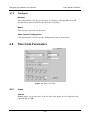
1
DolbyRemote Installation and Operation P/N 91659 Issue 1 DolbyRemote Installation and Operation Dolby Laboratories Inc Corporate Headquarters Dolby Laboratories Inc 100 Potrero Avenue San Francisco, CA 94103-4813 Telephone 415-558-0200 Facsimile 415-863-1373 www.dolby.com European Licensing Liaison Office Dolby Laboratories Wootton Bassett Wiltshire, SN4 8QJ, England Telephone (44) 1793-842100 Facsimile (44) 1793-842101 Far East Dolby Laboratories International Services, Inc. Japan Branch Fuji Chuo Building 6F 2-1-7, Shintomi, Chuo-ku Tokyo 104-0041 Japan Telephone (81) 3-5542-6160 Facsimile (81) 3-5542-6158 Dolby Laboratories Representative Office 7/Fl., Hai Xing Plaza, Unit H 1 Rui Jin Road (S) Shanghai 200023 China Telephone (86) 21-6418-1015 Facsimile (86) 21-6418-1013 LIMITATION OF LIABILITY: It is understood and agreed that Dolby Laboratories’ liability whether in contract, in tort, under any war-ranty, in negligence or otherwise shall not exceed the cost of replacement of the defective software and under no circumstances shall Dolby Laboratories be liable for incidental, special, direct, indirect or consequential damages (including but not limited to damage to software or recorded audio or visual material), or loss of use, revenue or profit even if Dolby Laboratories or its agents have been advised, orally or in writing, of the possibility of such damages. Dolby, DolbyRemote, Dolby Pro Logic, Dolby Digital Surround EX, AC-3 and the double-D symbol are trademarks of Dolby Laboratories. Windows 95 and Windows NT are registered trademarks of Microsoft Corporation. 1999 Dolby Laboratories Inc. All rights reserved. P/N 91659 Issue 1 S99/12613 ii DolbyRemote Installation and Operation Table of Contents List of Figures..............................................................................................................................v Chapter 1 Introduction........................................................................................................... 1-1 1.1 DolbyRemote Overview........................................................................................... 1-1 1.2 DolbyLoad................................................................................................................ 1-1 1.3 Requirements............................................................................................................ 1-1 1.3.1 PC System Requirements............................................................................ 1-1 1.3.2 DP Firmware............................................................................................... 1-2 1.4 Software Installation................................................................................................. 1-2 1.5 Cable Installation...................................................................................................... 1-3 Chapter 2 Establishing Communication........................................................................... 2-1 2.1 Starting DolbyRemote .............................................................................................. 2-1 2.1.1 Device Type ................................................................................................ 2-1 2.1.2 Communications ......................................................................................... 2-1 2.1.3 Off-Line ...................................................................................................... 2-2 2.2 Additional Devices ................................................................................................... 2-3 2.3 Removing Devices.................................................................................................... 2-4 Chapter 3 Disk Files ............................................................................................................... 3-1 3.1 Saving and Restoring Configurations....................................................................... 3-1 3.2 Exporting Configurations ......................................................................................... 3-1 Chapter 4 Dolby Digital Parameters................................................................................... 4-1 4.1 Audio Service Parameters ........................................................................................ 4-1 4.1.1 Input Meters ................................................................................................ 4-1 4.1.2 Data Rate..................................................................................................... 4-2 4.1.3 Clock Source............................................................................................... 4-2 4.1.4 Audio Coding Mode ................................................................................... 4-2 4.1.5 LFE Enable ................................................................................................. 4-3 4.1.6 Bitstream Mode........................................................................................... 4-3 4.1.7 Dialog Normalization ................................................................................. 4-3 4.1.8 Audio Bandwidth ........................................................................................ 4-3 4.1.9 Encoder Control .......................................................................................... 4-4 4.1.10 Coding Delay .............................................................................................. 4-5 4.1.11 Unit Name................................................................................................... 4-5 4.2 Preprocessing............................................................................................................ 4-6 4.2.1 Input Filtering ............................................................................................. 4-6 4.2.2 Surround Channel Processing ..................................................................... 4-7 4.2.3 Dynamic Range Compression..................................................................... 4-7 4.3 Bitstream Info........................................................................................................... 4-8 4.3.1 Bitstream Information................................................................................. 4-8 4.3.2 Audio Production Information.................................................................... 4-9 iii DolbyRemote Installation and Operation 4.4 4.5 4.6 4.7 4.8 Dual Mono................................................................................................................ 4-9 4.4.1 Audio Service Configuration .................................................................... 4-10 4.4.2 Dynamic Range Compression................................................................... 4-10 4.4.3 Audio Production Information.................................................................. 4-10 Input and Output Settings....................................................................................... 4-11 4.5.1 Input .......................................................................................................... 4-11 4.5.2 Output ....................................................................................................... 4-12 4.5.3 Input Subcode Status Bits ......................................................................... 4-13 4.5.4 Test Tone Generation................................................................................ 4-13 4.5.5 Stream Number ......................................................................................... 4-14 Reference Input ...................................................................................................... 4-14 4.6.1 Reference Input......................................................................................... 4-14 4.6.2 Reference Input Subcode Status Bits........................................................ 4-15 Presets..................................................................................................................... 4-15 4.7.1 Recall ........................................................................................................ 4-15 4.7.2 Configure .................................................................................................. 4-15 Time Code Parameters ........................................................................................... 4-16 4.8.1 Input .......................................................................................................... 4-16 4.8.2 Current Time Code ................................................................................... 4-17 4.8.3 Start Timec Code and Stop Time Code Values ........................................ 4-17 4.8.4 Preset......................................................................................................... 4-17 4.8.5 Resume...................................................................................................... 4-18 Chapter 5 Troubleshooting .................................................................................................. 5-1 5.1 Opening a Device ..................................................................................................... 5-1 5.2 Further Information .................................................................................................. 5-2 iv DolbyRemote Installation and Operation List of Figures 2-1 2-2 2-3 2-4 4-1 4-2 4-3 4-4 4-5 4-6 4-7 4-8 DolbyRemote Open Device Window............................................................................ 2-1 Device Off Line............................................................................................................. 2-2 DolbyRemote Window.................................................................................................. 2-3 Two Encoders Controlled.............................................................................................. 2-3 Audio Service Parameters ............................................................................................. 4-1 Preprocessing Tab ......................................................................................................... 4-6 Bitstream Info Tab......................................................................................................... 4-8 Dual Mono Tab............................................................................................................ 4-10 Input/Output Tab ......................................................................................................... 4-11 Reference Input ........................................................................................................... 4-14 Presets Tab................................................................................................................... 4-15 Time Code Tab ............................................................................................................ 4-16 v DolbyRemote Installation and Operation Chapter 1 Introduction 1.1 DolbyRemote Overview The DolbyRemote application is used to remotely control the entire range of Dolby Laboratories Inc. Dolby Digital encoders. Key features of the software include: ! ! ! ! 1.2 Control of several Dolby professional audio products from a single instance of the DolbyRemote application, hardware permitting. Off-line mode, without the presence of a unit, to create and edit parameter files. Off-line mode may be useful to demonstrate the operation of an encoder without the presence of the encoder hardware. Save a unit configuration in a file on a PC. Restore the unit’s configuration from a saved DolbyRemote file. Export an encoder’s configuration in human readable form in either text or HTML format. DolbyLoad The DolbyLoad application, for downloading new encoder firmware, is included with DolbyRemote as a convenience to customers. See the encoder firmware upgrade documentation for downloading instructions. 1.3 Requirements 1.3.1 PC System Requirements The minimum PC system requirements include a Pentium® 90 processor and either: • Windows® 95 with 16 Megabytes of memory, or • Windows®NT 4.0, Service Pack 3, and 24 Megabytes of memory. Additional memory may be needed to run other applications simultaneously. 1-1 DolbyRemote Installation and Operation 1.3.2 Introduction Encoder Firmware DolbyRemote requires the following encoder firmware: 1.4 DP561 Version 6.30 or later DP567 Version 1.50 or later DP569 Version 1.11 or later Software Installation The DolbyRemote application is installed from two diskettes. 1. Remove any previously installed version of DolbyRemote using the Add/Remove Program command from the Control Panel. It is strongly recommended that you exit all Windows programs before beginning the installation. 2. Insert the DolbyRemote Software Install Disk 1 into the computer. 3. Click Start and Run. 4. Browse to the DolbyRemote diskette. Select setup.exe and click OK. 5. Please read the Limitation of Liability and Welcome screens before proceeding with the installation. 6. The default installation destination for DolbyRemote is C:\Program Files\Dolby Laboratories. Click Next to accept the default or click Browse to select an alternative location. 7. Use the program folder default Dolby Laboratories or enter an alternate folder name and click Next. 8. Insert the DolbyRemote Software Install Disk 2 when prompted to do so and click OK. 9. To use the Help files in HTML format, click Yes. When the update is complete click OK. If a previous copy of DolbyRemote has been installed this prompt may not appear. 10. DolbyRemote installation is complete. 1-2 DolbyRemote Installation and Operation Introduction Microsoft DLL Files If you have an older version of Windows® 95, you may see an error message about Oleaut32.dll when you launch DolbyRemote. If this occurs, download and install the Windows Library Update from Microsoft (www.microsoft.com/windows95/downloads). 1.5 Cable Installation There are two types of serial interface used on Dolby products, RS-232 and RS- 485. It is important to use the correct type of interface and the correct cable to ensure a reliable connection. Each RS-232 port on a PC must be connected to a single device, however, the application can control many RS-232 ports. For example, with five free RS-232 ports on a computer, five devices may be controlled with a single instance of the DolbyRemote application. A single RS-485 computer port may connect to several devices, provided the devices all have an RS-485 connection. DolbyRemote is shipped with a cable for RS-232 connection between a PC and the front panel of a DP567/DP569 encoder. Connection to a PC RS-232 communications port is made with the D-9 end of the cable. The other end of the cable connects to the Remote port on the front panel of the encoder. Additional cables may be purchased from Dolby Laboratories. RS-485 connection for the DP567/DP569 requires a separate cable, not provided. This connects to the rear panel serial port of the unit. Consult the product's users manual for RS-485 support information. Connection between a PC and a DP561 encoder requires a standard null modem cable. The DP561 has only an RS-232 connection. 1-3 DolbyRemote Installation and Operation Chapter 2 Establishing Communication 2.1 Starting DolbyRemote From the Windows Start button, select DolbyRemote from the folder in which you installed the DolbyRemote application. The Open Device window is displayed, Figure 2-1. Figure 2-1 DolbyRemote Open Device Window 2.1.1 Device Type Selects the Dolby encoder model to be controlled. Choices are DP561, DP567 or DP569. 2.1.2 Communications These settings control the communication parameters for the DolbyRemote application. The corresponding parameters must be set for the appropriate PC communications port. Port Select the computer communications port to be used. DolbyRemote allows COM1 through COM10. The correct port will depend on the computer configuration. Baud Rate The communication baud rate for the DP567 and DP569 may be set to 9,600, 19,200 or 38,400. The default rate for all encoders is 38,400. The baud rate is configurable 2-1 DolbyRemote Installation and Operation Establishing Communication through the front panel of the encoder. The rate you select in DolbyRemote must match the rate selected in the unit. Address The default address setting for the DP567 and DP569 is 0x8280. If the address has been changed from the front panel of the encoder, set the remote address accordingly. If DP561 is selected as the Device Type, only the Port parameter may be set; Baud and Address are fixed at 38,400 and 9080, respectively. 2.1.3 Off-Line The DolbyRemote application may be used off line, without the presence of an encoder. This allows configurations to be preprogrammed and stored. Off-line mode is selected by checking the Off Line box when opening a unit. Figure 2-2 Device Off Line Once the desired parameters have been set, as described above, click OK. The DolbyRemote Window is displayed. When the DolbyRemote application establishes communication with the unit, it will display the unit's current settings. 2-2 DolbyRemote Installation and Operation Establishing Communication Figure 2-3 DolbyRemote Window 2.2 Additional Devices The DolbyRemote application can control several Dolby professional audio products. If you have more than one device you may control them all from a single instance of the DolbyRemote application, hardware permitting. To add additional encoders, click the New button or select File, New Device. The Open Device window is again displayed. See Section 2.1 for parameter details. Figure 2-4 Two Encoders Controlled 2-3 DolbyRemote Installation and Operation 2.3 Establishing Communication Removing Devices To remove, or discontinue the remote control of a device, click Close or select File, Close Device. 2-4 DolbyRemote Installation and Operation Chapter 3 Disk Files 3.1 Saving and Restoring Configurations DolbyRemote can save the configuration of the active device so that it can easily be recalled later. The file extension for these configurations is .dby and can only be read with DolbyRemote. Configurations can be transferred between different devices of the same type, without complication, using this function. Configurations saved by one encoder type (DP561/7/9) can be opened by a different encoder (DP561/7/9) as long as the configuration contained within the file is valid for both devices. It is advisable, however, to confirm unit parameters when transferring files in this way, as each different encoder type has some unit specific commands. The DolbyRemote file format is different from the Ac3Enc (original DP561 remote) file format, so these files may not be opened in the DolbyRemote application. Configuration files can be opened or saved from the File menu, or from buttons on the Tool Bar. Open Configuration File This restores the configuration of the saved file into the current device. Save Configuration File This saves the current device configuration to a file. 3.2 Exporting Configurations Export file gives two different options for saving the current configuration as a file that can be read and printed outside of the remote software. It is not possible to use these file types to configure a unit. You may export the current settings in either a text file or an HTML file. You should be able to view and print the HTML file with any standard web browser. 3-1 DolbyRemote Installation and Operation DolbyRemote Installation and Operation Chapter 4 Dolby Digital Parameters This chapter briefly describes each of the parameters available in the windows of DolbyRemote. It is designed as a quick reminder for experienced users or as an introduction for new users rather than the full explanation that will be required. Detailed information about each encoder setting can be found in the relevant encoder user’s manual or in the pages of the Dolby Digital Professional Encoding Manual. 4.1 Audio Service Parameters Figure 4-1 Audio Service Parameters 4.1.1 Input Meters Input Meters show the input level of the channels enabled in the current encoding mode in dBFS. 4-1 DolbyRemote Installation and Operation 4.1.2 Dolby Digital Parameters Data Rate Data Rate determines the bit rate of the encoded Dolby Digital bitstream. All data rate options are allowed, however, selection of the data rate is dependent on the settings of the Audio Coding Mode, Sample Rate and Auxiliary Data parameters. Certain low data rates may not be supported in all channel modes. For example rates 56, 64 and 80 kbps are only supported in 1/0 channel modes. 4.1.3 Clock Source Clock Source is a parameter that specifies the reference clock source for the encoding process as well as the reference for the output signal. The encoder will not produce a valid output signal if a clock source is not present. A green indicator is present for a valid source, a red indicator will be present for an invalid source. There are three types of clock sources: • Digital Input: a valid AES/EBU signal must be present at the Dig In 1/2 input. • Ref In: a valid AES/EBU signal must be present at the Ref In input. • Internal (48, 44.1 or 32 kHz): always valid when selected. Dig In 1/2 is the only input that may function as both an Input Source and Clock Source simultaneously. The clock source setting also controls the state of the internal sample rate conversion (SRC). SRC is disabled for the Digital Input and Ref In - SRC Off settings. SRC is enabled for the Ref In - SRC On and Internal clock source settings. There are some restrictions on the clock source selection that are enforced by the DolbyRemote application: • If Ref In-SRC On or an Internal clock source is selected the current Input Format must be PCM. • If Digital Input or an Internal clock source is selected, the Multiplex Mode must be disabled. • If Internal 32 kHz is selected the output mode must be Professional 32-bit • 4.1.4 or the Data Rate must be less than 448 kbps. If an internal clock source is selected, the frequency must be consistent with the coding delay and the auxiliary data input selection. See the DP567/DP569 user’s manual for details. Audio Coding Mode Audio Coding Mode defines the number of full-bandwidth audio channels within the encoded bitstream and also indicates the channel format. The audio coding mode is 4-2 DolbyRemote Installation and Operation Dolby Digital Parameters designated as two numbers, A/B, with A indicating the number of front channels, and B indicating the number of rear (surround) channels. The following table lists all eight modes and defines which input channels are used for encoding based on the selected mode. Channel names are designated as follows: Left (L), Right (R), Center (C), Left Surround (Ls), and Right Surround (Rs). Note that the Ls channel is the surround source for modes having a single surround channel (2/1, 3/1). In the case of mode 1+1, two completely independent program channels can be sourced from the L and R inputs (dual mono) and encoded into the output bitstream. 1+1 mode is not suitable for DVD or DTV applications. The Audio Coding Mode options available for the DP567 are 1+1 Dual Mono, 1/0 Mono and 2/0 Stereo. Table 4-1 Audio Coding Modes Audio Coding Mode 1+1 (Dual Mono) 1/0 (Mono) 2/0 (Stereo) 3/0 2/1 3/1 2/2 3/2 4.1.5 Encoded Channels L, R C L, R L, C, R L, R, Ls L, C, R, Ls L, R, Ls, Rs L, C, R, Ls, Rs LFE Enable LFE Enable determines whether the low frequency effects channel is enabled. This is dependent on the setting of the audio coding mode and is only active with coding modes greater than two channels. This option is also not available on the DP567. 4.1.6 Bitstream Mode Bitstream Mode is an informational parameter that indicates the data information service of the encoded Dolby Digital bitstream. It does not affect internal Dolby Digital encoding. 4.1.7 Dialog Normalization Dialog Normalization allows the user to set the value of dialnorm, a parameter that tells the decoder how much the average dialogue level of the encoded audio is below digital full scale. The decoder uses this to normalize the replay level. This means 4-3 DolbyRemote Installation and Operation Dolby Digital Parameters many different program types, with different reference levels, can be encoded with full dynamic range and then be decoded to give a uniform loudness level. 4.1.8 Audio Bandwidth Audio Bandwidth displays the current audio bandwidth of the main channels. This is dependent on the number of channels being encoded and the data rate. 4.1.9 Encoder Control Pass Through Pass Through indicates if the unit is in pass through mode. Pass Through mode allows the encoder to pass pre-encoded inputs to the main digital output either as a single bitstream or as part of a multiplexed bitstream. A valid clock source must be present when this mode is enabled. Bypass Bypass is typically used to route the output of a secondary (standby) encoder to the switched audio output of the primary encoder. To enable this function, the Bypass In connector of the primary encoder must be linked to the Main Out connector of the secondary (standby) encoder. Bypass Mode routes the Bypass In source directly to the Switched Output of the primary encoder. When Bypass Mode is disabled, the Main Output is routed directly to the Switched Output. Requested Encoder State Clicking on the Stop button manually disables the encoding process. Clicking the Encode button enables encoding to take place, if all required inputs are present. Activating Time Code Ctrl enables and disables the encoding process based on time code start and stop values. Figure 4-2 Encoder Stop and Start Buttons Time code control can only be entered on the following conditions: • Input Format is set to PCM. • Multiplex Mode is disabled. • Time code controlled preset recalls are not pending. 4-4 DolbyRemote Installation and Operation Dolby Digital Parameters Encoder State Encoder State displays the status of encoding for the current device. There are three options for the encoder state: • Not Encoding—the user has requested that the unit start encoding, but the encoder is unable to encode because it is missing a required input signal. • Encoding—the unit is encoding • Stopped—the user has directed the unit to not encode 4.1.10 Coding Delay There are displays for both the requested and current coding delay values. The requested and current values may be different if the unit is unable to provide the requested delay, based on the value of other inputs. For example, suppose the clock source is digital input, a DP569 is receiving a 48 kHz input, and the Coding Delay is set to 170 ms. In this case, both the requested and the actual coding delays will be 170 ms. Then the input changes to 44.1 kHz. At 44.1 kHz, the smallest legal coding delay is 195 ms. The DP569 will switch to a 195ms coding delay. The actual coding delay will display 195 ms, while the requested coding delay will continue to display 170 ms. Current Current Coding Delay displays the time from the first sample of a particular frame received by the encoder to the time the first word of the coded output frame appears in the output bitstream. Requested Enter a value for the Coding Delay in milliseconds. Any changes made to the delay setting will take place immediately by deleting output frames and/or adding gaps to the output bitstream as necessary. The minimum and maximum delay times depend on the encoder unit, DP567 or DP569, and the input sampling rate. Internal/External Select Internal to specify the amount of coding delay in milliseconds. If External mode is selected this option is grayed out and the delay is determined from the signal applied to the TTL delay input. 4.1.11 Unit Name The unit may be given a name, 16 characters maximum. 4-5 DolbyRemote Installation and Operation 4.2 Dolby Digital Parameters Preprocessing Figure 4-3 Preprocessing Tab 4.2.1 Input Filtering Deemphasis The Deemphasis parameter controls whether or not 50/15 µs digital deemphasis may be applied to the main input channels before the Dolby Digital encoding process is performed. If Deemphasis is set to Disabled, deemphasis will never be applied and the emphasis channel status bit of input signals will be ignored. If the parameter is set to Automatic, digital deemphasis will automatically be applied to input signals if the emphasis channel status bit indicates 50/15 µs pre-emphasis has been applied. The state of Deemphasis and the channel status bit will be ignored whenever pre-encoded bitstreams are being received, Pass Through mode is active. DC Highpass Filter DC Highpass Filter controls whether or not a DC blocking 3 Hz highpass filter is applied to the main channel inputs before the Dolby Digital encoding process. Bandwidth Lowpass Filter Bandwidth Lowpass Filter controls whether or not a bandwidth limiting lowpass filter is applied to the main input channels before the Dolby Digital encoding process. LFE Lowpass Filter LFE Lowpass Filter controls whether or not a 120 Hz lowpass filter is applied to the LFE channel before the Dolby Digital encoding process. This parameter is ignored if the LFE channel is disabled. This parameter is not available on the DP567. 4-6 DolbyRemote Installation and Operation 4.2.2 Dolby Digital Parameters Surround Channel Processing 90 Degree Phase Shift 90 Degree Phase Shift controls whether or not a 90-degree phase shift is applied to the surround channel(s) before the Dolby Digital encoding process. Its use enables decoders to create a Dolby Surround compatible two-channel downmix. This parameter is disabled if the encoding mode does not include any surround channels. This parameter is not available on the DP567. 3 dB Attenuation 3 dB Attenuation controls whether or not the surround channel(s) are attenuated by 3 dB before the Dolby Digital encoding process. This allows material mixed in a room calibrated film style (left and right surround channels are calibrated –3dB with respect to the front channels) to be converted to video style calibration (all channels are calibrated to the same level) by attenuating the surround channel(s) by 3 dB. This parameter is disabled if the encoding mode does not include any surround channels. This parameter is not available on the DP567. 4.2.3 Dynamic Range Compression Dolby Digital has the ability to transmit full dynamic range audio for some listeners as well as additional information which instructs a decoder on how to reduce the dynamic range for others. For example, some people will want a reduced dynamic range for late night listening, or because they have a smaller replay system. The choice of Compression Characteristic and Dialog Normalization parameters as well as the program material control the generation of this extra data. Compression Characteristic Compression Characteristic selectsthe compression characteristic that will be applied to the encoded Dolby Digital bitstream. The encoder includes six dynamic range compression modes that correspond to commonly used compression settings. Any mode can be selected at any time. The compression modes apply only to the encoded signal and are not applicable when the Pass Through mode is active. When in the 1+1 Channel Mode, the selected Dynamic Range Compression applies to both mono channels. The actual compression applied to each channel, in this case, is independent, however they share the same compressor characteristics. RF Overmodulation Protection RF Overmodulation Protection controls whether or not the Dolby Digital signal is protected against overmodulation distortion when decoded in RF compression mode and subsequently modulated onto an RF carrier. Typical applications include digital television set-top box systems in which decoded audio and video are combined into a composite RF output signal. Note that this parameter has no effect on Line Out or 4-7 DolbyRemote Installation and Operation Dolby Digital Parameters custom compression modes. The default setting for RF Overmodulation Protection is disabled. This parameter is not available on the DP567. Input Level Meter Input Level Meter shows the input signal that the compressor is using to determine the amount of boost or cut. This signal is derived by taking the largest of the individual channel signal levels and then attenuating by the dialnorm amount (see Section 4.1.7). Line Mode and RF Mode Line Mode and RF Mode meters show the current value of the cut and boost words being included in the Dolby Digital bitstream. Red shows compression (cut) and green shows boost, calibrated in dB. Line mode represents a two-channel decoded output designed for connection to a stereo hi-fi, for example, RF mode represents a signal designed for re-modulation onto an RF carrier. 4.3 Bitstream Info Figure 4-4 Bitstream Info Tab 4.3.1 Bitstream Information Center Mix Level Center Mix Level is a parameter that indicates to the decoder the nominal downmix level of the center channel with respect to the left and right channels when listening in stereo. This is only active when in 3/0, 3/1, 3/2 coding modes. This parameter is not available on the DP567. 4-8 DolbyRemote Installation and Operation Dolby Digital Parameters Surround Mix Level Surround Mix Level is a parameter that indicates to the decoder the nominal downmix level of the surround channel(s) with respect to the left and right channels when listening in stereo. This is only active when in 2/1, 2/2, 3/1, or 3/2 coding modes. This parameter is not available on the DP567. Dolby Surround Mode Dolby Surround Mode is a parameter that allows you to indicate when an encoded two-channel Dolby Digital bitstream is conveying a Dolby Surround encoded program. It causes A/V receivers to utilize Dolby Pro Logic decoding as well as Dolby Digital decoding when the material is flagged as Dolby Surround. This is only active when in the 2/0 coding mode. Copyright Bit Copyright Bit is an informational parameter that indicates whether or not the Dolby Digital bitstream is protected by copyright. Original Bitstream Original Bitstream is an informational parameter that allows you to indicate whether the encoded Dolby Digital bitstream is an original or a copy. 4.3.2 Audio Production Information Info Exists Info Exists is a flag to indicate whether the Mix Level and Room Type parameters are valid for this Dolby Digital bitstream. Mix Level Mix Level is an informational parameter that indicates the peak acoustic sound pressure level during the final audio mixing session of the encoded Dolby Digital bitstream. Room Type Room Type indicates the type and equalization of the mixing room used for the final audio mixing session of the encoded Dolby Digital bitstream. 4.4 Dual Mono These fields are only applied when the coding mode is set to 1+1. In this case these parameters apply to channel two. 4-9 DolbyRemote Installation and Operation Dolby Digital Parameters Figure 4-5 Dual Mono Tab 4.4.1 Audio Service Configuration Dialog Normalization Dialog Normalization sets the dialnorm value for channel two when in 1+1 Coding Mode only. 4.4.2 Dynamic Range Compression Input Level, Line Mode and RF Mode Input Level, Line Mode and RF Mode meters for channel two when in 1+1 Coding Mode only. The Compression Characteristic is the same as that applied to channel one in the pre-processing section. 4.4.3 Audio Production Information Mix Level, Room Type and Info Exists Mix Level, Room Type and Info Exists are informational parameters for channel two when in 1+1 Coding Mode only. 4-10 DolbyRemote Installation and Operation 4.5 Dolby Digital Parameters Input and Output Settings Figure 4-6 Input/Output Tab 4.5.1 Input Lock Status Lock Status shows whether the input channels for the current coding mode have been detected and locked by the encoder. Sample Rate Sample Rate shows the sample rate of the digital input channels. Integrity Integrity shows the data integrity of the digital input channels. Format Format is a control parameter that allows you to choose the format of the data received from the input source. Available Input Format selections are: • PCM: Dolby Digital encoding will be enabled. When analog is selected as the DP567 input source, the input format must always be PCM. • Pre-encoded: Pass-through mode will be enabled. Pre-encoded bitstreams move through the unit, unmodified, to the output. 4-11 DolbyRemote Installation and Operation Dolby Digital Parameters • Autodetect: Automatically detects and processes PCM and pre-encoded bitstreams. Invalid bitstreams will be assumed to be PCM data, and encoding will be enabled. Aux Data Aux Data allows you to indicate whether the auxiliary data field is present in the encoded Dolby Digital bitstream. When present, serial data will be received from the Aux Data Input port and added to the auxiliary data field of the output Dolby Digital bitstream. Three data rates are supported: 1200, 2400, and 9600 bits per second. Since the addition of auxiliary data reduces the number of bits available for audio data, the allowed auxiliary data rates are limited for some Dolby Digital data rates. Use of the Aux Data Input mode is restricted to the PCM input format and cannot be enabled if the Pre-encoded or Autodetect Input Format is selected. Aux Data Input may be used when the Multiplex Mode is enabled, however the auxiliary data will only be added to a bitstream encoded by the DP567 or DP569. Source Source allows you to select between analog and digital audio input sources. Only one input source can be active at a time. This parameter is not available on the DP569. Channel Assignment Channel Assignment allows you to determine the mapping of input sources to audio channels. Channel assignment is represented in the form A/B C/D E/F, where channels A through F are mapped to input sources 1 through 6, respectively. For example, when the Input Channels parameter is set to L/R C/LFE Ls/Rs, the 1/2 input is the source for the Left and Right channels, the 3/4 input is the source for the Center and Low Frequency Effects channels, and the 5/6 input is the source for the Left Surround and Right Surround channels. This parameter is not available on the DP567. In addition to the input channel assignment presets provided in the DP569, the DP561 also allows an arbitrary assignment of input channels. 4.5.2 Output Format Format allows you to determine the mode of the AES/EBU output bitstream and to specify how the data is packed within that bitstream. The selection is either professional or consumer and 16 or 32-bit. The default parameter is Professional 32bit. If Multiplex mode is currently enabled then it is not possible to output Professional 32-bit or Consumer modes. 4-12 DolbyRemote Installation and Operation Dolby Digital Parameters Audio Bit Audio Bit allows you to set the audio bit in the output bitstream as either audio or non-audio, data. Certain AES/EBU inputs may require this to be set to audio before they will record the encoded bitstream. Multiplex Mode Multiplex Mode allows multiple encoded bitstreams to be combined into the main digital output bitstream. When enabled, an internally encoded or pre-encoded Dolby Digital bitstream is multiplexed with other pre-encoded bitstreams contained within the reference-input signal. The reference input signal is used as the reference bitstream for the multiplexing operation. The resulting output bitstream will be a copy of the reference bitstream with the internally encoded or passed-through bitstream added to it. When Multiplex Mode is active, the DP567/9 overwrites the contents of the channel selected by the Output format. If the reference input contains a PCM signal, the DP567/9 overwrites the selected output channel with the internally encoded or preencoded bitstream but passes through the reference PCM signal on the opposite channel without modification. Autodetect and Pass Through modes are allowed when Multiplex Mode is active. The following options should be selected in order to enable Multiplex Mode: • • • • The Reference Input must be selected as the Clock Source. Time Code Control must be disabled. The Output format must be set to either Pro 16-bit Ch 1 or Pro 16-bit Ch 2. Any bitstreams detected in the Reference Input must have been encoded in the Pro 16-bit mode, and cannot be present in the same channel selected by the output format. Include Time Code Packets Include Time Code Packets determines whether the encoded output bitstream contains the associated time code information packets. 4.5.3 Input Subcode Status Bits Input Subcode Status Bits show the format, sample rate, emphasis and audio bit as indicated in the subcode of the digital input signal. 4.5.4 Test Tone Generation Test Tone activates an internally generated test signal as the input to the encoding process rather than the currently selected input signal. Enabling the Test Tone mode 4-13 DolbyRemote Installation and Operation Dolby Digital Parameters does not guarantee that a valid test tone will be produced at the output of the DP567 or DP569. Dolby Digital encoding must also be active, which requires that the selected clock source be valid. The selection of a Test Tone mode automatically overrides the input format settings. All other settings remain active. 4.5.5 Stream Number Input Input shows the input stream number for a pre-encoded signal present at the reference input. Output Output defines the stream number for the Dolby Digital output of the encoding process. The default is zero. If multiplex mode is currently active, the selected stream number cannot be identical to that of a stream currently being received. 4.6 Reference Input Figure 4-7 Reference Input 4.6.1 Reference Input Lock Status Lock Status shows whether the reference input has been detected and locked. Sample Rate Sample Rate shows the sample rate of the reference input. Integrity Integrity shows the data integrity of the reference input. 4-14 DolbyRemote Installation and Operation Dolby Digital Parameters Stream Number Stream Number shows the stream number for a pre-encoded bitstream present at the reference input. 4.6.2 Reference Input Subcode Status Bits These show the format, sample rate and audio bit as indicated in the subcode of the reference input signal. 4.7 Presets Presets 29 through 32 are factory defaults and cannot be overwritten. Figure 4-8 Presets Tab 4.7.1 Recall Click on any of the 32 preset buttons to recall one of the 32 complete configurations for the encoder. These presets are stored internally within the decoder, not within the DolbyRemote application. Saved presets may be recalled from either the remote application or the front panel. 4-15 DolbyRemote Installation and Operation 4.7.2 Dolby Digital Parameters Configure Number Select the number of the present you wish to configure, 1 through 28. Presets 29 through 32 are factory defaults and cannot be overwritten. Name Enter a name, if desired, for the preset. Save Current Configuration Click this button to save the current configuration in the selected preset. 4.8 Time Code Parameters Figure 4-9 Time Code Tab 4.8.1 Input Source Source allows you to select one of the two time code inputs for receiving time code signals LTC or VITC. 4-16 DolbyRemote Installation and Operation Dolby Digital Parameters Status Status shows whether there is a valid time code signal present on the selected input. 4.8.2 Current Time Code Current Time Code shows both the current time code value and frame rate in HH:MM:SS:FF format. If no time code input is present this box will be grayed out. 4.8.3 Start Time Code and Stop Time Code Values When the Encoder State parameter is set to Time Code Ctrl, the encoder is placed in a state where the internal encoding process begins and ends at specific user definable times. The Start Time Code enables the encoder to wait until a specified start time occurs before encoding frames, based on the selected time code input signal. Encoding will continue, assuming all required encoding conditions are met, until Stop Time Code time is reached. Before the start time and after a stop time, encoded frames will not appear on the encoder output (adjusting for internal pipeline delays). This mode is used to create encoded streams of a specific length and position in time primarily for DVD authoring. The start and stop times are specified in the format HH:MM:SS:FF:ssss where: HH = hours (00 to 23) MM = minutes (00 to 59) SS = seconds (00 to 59) FF = frames (00 to 29) ssss = samples (0000 to 1535) The first sample of the first encoded frame will correspond to the exact sample specified by the start time. The last sample of the last encoded frame cannot be specified because encoding must end at a Dolby Digital frame boundary. For this reason, the samples field of Stop Time Code is not user adjustable. Encoding will actually end at the completion of the first Dolby Digital frame following the specified stop time. At the completion of encoding the actual value of stop time, including samples, will be shown in the Stop Time Code display. This samples value can then be used to offset the next piece of encoded material, if necessary, to maintain A/V sync. See Section 4.8.5, Resume. 4.8.4 Preset A special recall preset state allows a selected preset to be recalled at a specific time, based on the time code input. When this has been enabled, the selected preset will be considered pending until the specified time is reached, and the preset becomes active. 4-17 DolbyRemote Installation and Operation Dolby Digital Parameters For instance, you might want the Stereo Music preset to take effect at time code 00:12:22:12. To do this, you follow the following procedure: 1. Select the Time Code tab page 2. Enter 00:12:22:12 in the Start Time Code field 3. Select Stereo Music in the Preset Pending field. When time code 00:12:22:12 occurs, the unit will switch to the Stereo Music preset. The Preset Pending field will display None and the Current Preset field will display Stereo Music. There are a few restrictions on the recall preset on time code feature: • Once you have selected a start time and a preset, you can’t change the start time. If you want to change the start time, you must follow this procedure: 1. Select None in the Preset Pending field. 2. Enter the new Start Time Code value. 3. Select the correct preset in the Preset Pending field. 4.8.5 • Pressing any of the preset buttons, immediately invoking a preset, cancels any pending preset • If the unit is in Time Code Control mode, start and stop encoding is determined by time code, it cannot also recall a preset based on time code. In other words, the unit can either use time code to determine when to start and stop encoding, or to determine when to recall a preset, but not both. Resume This button copies the Stop Time Code value to the Start Time Code value to permit seamless encoding of two sections of continuous material. 4-18 DolbyRemote Installation and Operation Chapter 5 Troubleshooting 5.1 Opening a Device If the DolbyRemote application is unable to communicate with the unit, check the following: DP569/DP567 Make sure the unit is in remote mode (press shift-left arrow). The remote LED should be lit. Make sure that you are either using a RS-232 connection through the front panel or a RS-485 (RS422 for DP567) connection through the rear panel. Verify that the baud rate and device address of the unit to be controlled match the parameters given to the DolbyRemote application in the Open Device window. On the unit, these parameters are found in the Operating Mode section of the encoder setup menu. DP561 Make sure the unit is in remote mode; press shift-C on the keyboard. The VGA screen should show that the unit is in remote mode. It is possible to program the DP561 to always boot up into remote mode. Consult the product manual for details. Make sure you are using a RS-232 connection into COM 1 of the DP561. This must be made using a null modem cable. General It is possible that hardware constraints on the controlling PC can cause problems with the remote connection. Both devices transfer data continuously to update dynamic information such as meter values. If the port is using a shared IRQ with another device then it is possible that the connection may be lost. In this case using another COM port can solve the problem. If the connection is lost the unit will continue to operate with the current set of parameters contained immediately before the connection was broken, however it is not advisable to use the unit in this way if this problem persists. 5-1 DolbyRemote Installation and Operation 5.2 Troubleshooting Further Information If you purchased this software through a dealer or systems integrator, please contact them for technical support. Information is also available at our web site www.dolby.com. Dolby Laboratories can be contacted at the following addresses: Dolby Laboratories Inc 100 Potrero Avenue San Francisco, CA 94103-4813 USA Main: (415) 558-0200 Fax: (415) 863-1373 E-mail: [email protected] 8:00 am - 5:30 p.m., Monday – Friday Dolby Laboratories Inc Wootton Bassett Wiltshire SN4 8QJ England Main: (44) 1793-842100 Fax: (44) 1793-842101 E-mail: [email protected] 8:30 am - 4:30 p.m., Monday - Friday 5-2