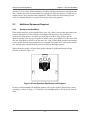
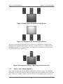
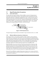
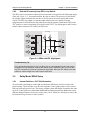
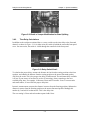
1
Dolby Surround
Mixing Manual
Part No. 91536
Issue 2
Dolby Surround Mixing Manual
Dolby Laboratories, Inc.
USA Headquarters
Dolby Laboratories, Inc.
100 Potrero Avenue
San Francisco, CA 94103-4813
Telephone 415-558-0200
Facsimile 415-863-1373
UK European Licensing Liaison Office
Dolby Laboratories
Wootton Bassett
Wiltshire SN4 8QJ England
Telephone (44) 1793-842100
Facsimile (44) 1793-842101
Far East
Dolby Laboratories International Services, Inc.
Japan Branch
Fuji Chuo Building 6F
2-1-7, Shintomi, Chuo-ku
Tokyo 104-0041 Japan
Telephone (81) 3-5542-6160
Facsimile (81) 3-5542-6158
Dolby Laboratories International Services (Shanghai) Co., Ltd.
03-07a, 18/F., The Center
989 ChangLe Road
Shanghai 200031 China
Telephone (86) 21-6113-3456
Facsimile (86) 21-6113-3400
This manual is dedicated to Bob “Spider” Seiderman, whose insight, experience and guidance
through more than 20 years of audio mixing helped to make this manual possible. Without Bob’s
input, the success of Dolby Surround for live sporting events would have been far more difficult. His
expertise and willingness to share his thoughts with others are reflected in several sections of this
manual. It is with deep sorrow that we have had to say our goodbyes to Bob so early in his life.
Thank you Bob for letting us share some of your expertise with other audio engineers in the industry.
Your friends at Dolby Laboratories,
Jim Hilson
David Gray
Michael DiCosimo
Dolby and the double-D symbol are registered trademarks of Dolby Laboratories.
© 2005 Dolby Laboratories, Inc. All rights reserved.
S05/12280/16103
Issue 2
Confidential information for Dolby Laboratories Licensees only. Unauthorized use, sale, or duplication is prohibited.
ii
Dolby Surround Mixing Manual
Table of Contents
List of Figures .................................................................................................................vi
List of Tables.................................................................................................................viii
Chapter 1 Introduction ................................................................................................ 1-1
Chapter 2 Technical Guidelines ................................................................................. 2-1
2.1 Equipment from Dolby Laboratories ............................................................ 2-1
2.1.1 Dolby Model SEU4 Surround Encoding Unit................................... 2-1
2.1.2 Dolby Model SDU4 Surround Decoding Unit .................................. 2-1
2.2 System Information ...................................................................................... 2-2
2.2.1 Room Layouts.................................................................................. 2-2
2.2.2 Control Rooms................................................................................. 2-3
2.2.3 Remote Trucks ................................................................................ 2-4
2.2.4 Critical Listening Rooms.................................................................. 2-4
2.2.5 Consumer Decoders........................................................................ 2-4
2.3 Additional Equipment Required ................................................................... 2-5
2.3.1 Speakers and Amplifiers.................................................................. 2-5
2.3.2 Center Channel Speaker ................................................................. 2-7
2.3.3 Smaller Center Channel Speakers .................................................. 2-9
2.3.4 Surround Channel Speakers ......................................................... 2-10
2.3.5 Surround Speaker Location........................................................... 2-10
2.3.6 Audio Consoles.............................................................................. 2-11
2.3.7 Monitor Path .................................................................................. 2-11
2.3.8 Speaker Sound Pressure Level..................................................... 2-13
2.3.9 SPL Meters .................................................................................... 2-14
2.3.10 Phase Scope ................................................................................. 2-14
Chapter 3 System Installation .................................................................................... 3-1
3.1 Signal Routing Audio Connections .............................................................. 3-1
3.1.1 Inputs and Outputs .......................................................................... 3-1
3.1.2 Wiring for Maximum Immunity to Interference................................. 3-1
3.2 Signal Flow Options—Encoder.................................................................... 3-3
3.2.1 Basic Recording Setup with Auxiliary Bus Surround Feed ............. 3-3
3.2.2 Basic Recording Setup with Film Panning Console ........................ 3-4
3.2.3 Basic Recording Setup with 2 Stereo Bus Output........................... 3-4
3.3 Signal Flow Options—Decoder.................................................................... 3-4
3.3.1 Recording Setup with Monitor Section of Console.......................... 3-4
3.3.2 Recording Setup with Surround-Ready Monitor Section of Console.... 3-5
3.3.3 Live Broadcast Setup....................................................................... 3-5
3.3.4 Live Broadcast Setup with Fail-Safe ............................................... 3-6
3.3.5 Monitoring Music Premixes for Film ................................................ 3-6
3.4 Dolby Model SEU4 Setup ............................................................................ 3-7
3.4.1 Surround Active LED ....................................................................... 3-7
3.4.2 External Processing Loop (EPL) Loop Switch................................. 3-8
3.5 Dolby Model SDU4 Setup ............................................................................ 3-8
iii
Dolby Surround Mixing Manual
3.6
3.5.1 Internal Switches—CAT 344 information ........................................ 3-8
3.5.2 Center Speaker Switch .................................................................... 3-9
3.5.3 Wake-up State ............................................................................... 3-10
3.5.4 Local/Remote Fader ...................................................................... 3-10
3.5.5 EPL Switch .................................................................................... 3-11
Cat 150E Card Settings ............................................................................. 3-12
3.6.1 Bass Splitting Modification............................................................. 3-12
3.6.2 Time Delay Calculations................................................................ 3-13
Chapter 4 System Setup ............................................................................................. 4-1
4.1 Encoder Alignment....................................................................................... 4-1
4.2 Decoder Alignment ...................................................................................... 4-2
4.2.1 Input Levels ..................................................................................... 4-2
4.2.2 Output Levels................................................................................... 4-3
4.3 Room EQ ..................................................................................................... 4-3
4.3.1 ANSI/SMPTE 202M X-Curve........................................................... 4-4
4.3.2 ANSI/SMPTE 222M Modified X-Curve............................................ 4-4
4.3.3 Recording Studios—Music Mixing................................................... 4-5
4.3.4 Near-Field Monitors ......................................................................... 4-5
Chapter 5 Mixing Techniques..................................................................................... 5-1
5.1 Announcers and Dialogue............................................................................ 5-1
5.2 Interior Effects .............................................................................................. 5-1
5.3 Positioning of the Stereo Image................................................................... 5-1
5.4 Panning Sounds........................................................................................... 5-2
5.5 Stacking Encoded Tracks ............................................................................ 5-2
5.6 Magic Surround............................................................................................ 5-2
5.7 Decoder Mistracking and Steering Artifacts ................................................ 5-3
5.8 Surround Pumping ....................................................................................... 5-3
5.9 Proper Surround Level and Content ............................................................ 5-4
5.10 Limiters, Delays, Reverb Units, Other Effects Processors .......................... 5-4
5.11 Mono to Stereo Synthesizers....................................................................... 5-4
5.12 Dolby Surround Compatible Processors ..................................................... 5-4
5.13 Mono, Stereo, and Dolby Surround Compatibility ....................................... 5-5
5.14 Monitoring .................................................................................................... 5-5
5.15 Common Pitfalls ........................................................................................... 5-5
Chapter 6 Live Broadcast Applications..................................................................... 6-1
6.1 Transmission Path Considerations .............................................................. 6-1
6.2 Phase Chasers ............................................................................................ 6-1
6.3 Station Limiters ............................................................................................ 6-1
6.4 Station Processing ....................................................................................... 6-1
6.5 Headroom .................................................................................................... 6-2
6.6 Stereo Synthesizers in Transmission Paths ................................................ 6-2
Chapter 7 Video Games and Multimedia ................................................................... 7-1
7.1 Introduction .................................................................................................. 7-1
7.2 Normal Dolby Surround Encoding ............................................................... 7-1
7.3 Polarity Inversion ......................................................................................... 7-1
7.4 Phase Encoding ........................................................................................... 7-2
iv
Dolby Surround Mixing Manual
7.5
7.6
7.7
7.8
7.9
7.10
Dolby Surround Game Mode Encoding ....................................................... 7-2
Modification Principle ................................................................................... 7-3
Application Information ................................................................................ 7-4
SEU4 Game Mode Alignment...................................................................... 7-5
Testing Game Mode Encoding with an Audio Console ............................... 7-5
Game Playback............................................................................................ 7-6
Chapter 8 Theory of Operation................................................................................... 8-1
8.1 Encoder........................................................................................................ 8-1
8.2 Decoder........................................................................................................ 8-1
Chapter 9 Miscellaneous Information........................................................................ 9-1
9.1 Contacting Dolby Laboratories .................................................................... 9-1
9.2 Software Identification and Trademark Usage ............................................ 9-2
9.3 Dolby Surround Consultants ........................................................................ 9-2
9.4 Dolby Surround Software Lists .................................................................... 9-3
v
Dolby Surround Mixing Manual
List of Figures
Figure
2-1
2-2
2-3
2-4
2-5
2-6
2-7
2-8
2-9
2-10
2-11
2-12
2-13
2-14
2-15
2-16
2-17
2-18
2-19
2-20
2-21
2-22
3-1
3-2
3-3
3-4
3-5
3-6
3-7
3-8
3-9
3-10
3-12
3-13
3-14
3-15
3-16
3-17
3-18
3-19
3-20
4-1
4-2
4-3
Description
Page
Dolby Model SEU4 and SDU4 ..................................................................... 2-1
Typical Room Layout ................................................................................... 2-2
Sound Field Pattern with Two Surround Speakers...................................... 2-3
Sound Field Pattern with Four Surround Speakers ..................................... 2-3
Large Listening Room with Surround Speaker Array .................................. 2-4
Front Speakers Equidistant from Engineer.................................................. 2-5
Wrong Soffit and Center Speaker Placement.............................................. 2-6
Listener in Sweet Spot ................................................................................. 2-7
Listener Shifted to Side................................................................................ 2-7
Defined Image.............................................................................................. 2-8
Front Speakers in the Same Horizontal Plane ............................................ 2-8
Ideal Setup—All Speakers Above Screen ................................................... 2-9
Ideal Setup—All Speakers Below Screen.................................................... 2-9
Compromised Setup—High-Frequency Drivers In Line .............................. 2-9
5.1-Channel System Room Layout............................................................ 2-10
Vertical Location of Surround Speakers in Control Room......................... 2-11
Typical Signal Flow .................................................................................... 2-11
Signal Flow through Console Monitor........................................................ 2-12
Modified Monitor Section of 2-Track Console............................................ 2-13
Radio Shack Analog and Digital SPL Meters ............................................ 2-14
Tektronix 760 Phase Scope Display of Center Channel Information ........ 2-15
Tektronix 760 Phase Scope—Typical Multichannel Information ............... 2-15
XLR Connector Pins .................................................................................... 3-1
Signal Routing—Stereo Bus and Auxiliary Sends ....................................... 3-3
Signal Routing—Film-Style Panning............................................................ 3-4
Signal Routing—Dual Stereo Bus................................................................ 3-4
Signal Routing—Console with Monitor Section ........................................... 3-5
Signal Routing—Monitor Section with 4 Channel Insert Points................... 3-5
Signal Routing—Live Broadcast .................................................................. 3-6
Signal Routing—Live Broadcast with Fail Safe ........................................... 3-6
Signal Routing—4-2-4 Monitoring................................................................ 3-7
SEU4 Front Panel with Surround Active LED On........................................ 3-7
SEU4 with EPL Highlighted ......................................................................... 3-8
CAT 344 Card Switches and Jumpers......................................................... 3-9
Center Speaker Switch Detail ...................................................................... 3-9
Wake-Up State Jumper Detail ................................................................... 3-10
Remote Fader and Connector ................................................................... 3-10
Remote Fader Switch Detail ...................................................................... 3-11
EPL Switch Detail....................................................................................... 3-11
Detail of Jumper Modification for Bass Splitting ........................................ 3-13
Delay Switch Detail .................................................................................... 3-13
Adjusting the Center Input Trim Control ...................................................... 4-2
Adjusting the Right Input Trim Control......................................................... 4-3
Adjusting the Center Output Trim Control.................................................... 4-3
vi
Dolby Surround Mixing Manual
4-4
4-5
7-1
7-2
7-3
7-4
7-5
7-6
7-7
8-1
8-2
Standard X-Curve ........................................................................................ 4-4
Modified X-Curves........................................................................................ 4-4
Phase Shifter and Positioner ....................................................................... 7-2
Signal Flow for Game Encoding .................................................................. 7-3
Dolby Surround Game Encoding ................................................................. 7-3
Game Mixer.................................................................................................. 7-4
Waveform of Game Encoded Signal ........................................................... 7-4
Positioner Function Via Audio Console ....................................................... 7-6
Game Audio Creation and Reproduction..................................................... 7-7
Dolby Surround Encoder.............................................................................. 8-1
Dolby Surround Pro Logic Decoder ............................................................. 8-2
vii
Dolby Surround Mixing Manual
List of Tables
Table
3-1
3-2
7-1
Description
Page
EPL Connections ....................................................................................... 3-12
Delay Switch Settings ................................................................................ 3-14
Dolby Surround Game Encoding Options.................................................... 7-6
viii
Dolby Surround Mixing Manual
Chapter 1
Introduction
Dolby® Surround is a format that enables the production and delivery of multi-dimensional
soundtracks for television, cable, consumer video, compact disc, video game and other stereo
media. Once created, Dolby Surround soundtracks can be recorded, broadcast and reproduced in
the same manner as any conventional stereo programs, including compatible monophonic
playback. Consumers equipped with Dolby Surround systems will experience a program’s full
measure of spatial dimensionality, just as they do from thousands of Dolby Stereo movies
currently available on home video media.
Many aspects of Dolby Surround soundtrack production are the same as those of stereo
soundtrack production. The main difference is that the mixing console must have at least three
and preferably four outputs to feed the Dolby Surround encoder. To complete the surround
system, additional speakers and amplifiers are needed to monitor the Center and Surround
channels via a Dolby Surround decoder.
In most cases the finished two-channel encoded soundtrack is all that will be recorded or
broadcast. However, in some cases it may be desirable to record the four-channel stems (Left,
Center, Right and Surround encoder input signals) onto separate tracks when further elements are
to be added later, such as with music pre-mixes for movie soundtracks.
This manual contains the information necessary for production personnel to properly produce
soundtracks in Dolby Surround.
1-1
Dolby Surround Mixing Manual
Chapter 2
Technical Guidelines
2.1
Equipment from Dolby Laboratories
The equipment described below exists in two versions. The newer one has much greater
immunity to RF interference, and as sold in Europe with a single power line voltage, is compliant
with the EMC standards of the European Union. Operationally the two versions are analogous,
and this manual applies to both. Older units have a “gold” finish to the tray and top, the more
recent ones a “silver” finish. The newer versions do not have removable front cover plates and
thumbscrews; to gain access to the plug-in modules and internal switches, remove the extruded
front panel (two screws on top and five underneath).
2.1.1
Dolby Model SEU4 Surround Encoding Unit
The SEU4 receives four input signals (Left, Center, Right, and Surround) from the audio console
and matrix encodes them into two output signals (Lt and Rt). The Lt and Rt signals are then
treated as any stereo signal would be for transmission and recording.
2.1.2
Dolby Model SDU4 Surround Decoding Unit
The SDU4 decodes the two-channel encoded signal (Lt and Rt) into four output signals (Left,
Center, Right and Surround) using Dolby® Surround Pro Logic® decoding technology. The unit
also provides switchable stereo and monophonic monitoring modes for evaluating mix
compatibility. A ganged master fader allows all four monitor output channels to be varied
together, allowing variations in listening level while maintaining playback balance and
calibration.
Figure 2-1 Dolby Model SEU4 and SDU4
It is important to listen through the decoder while mixing in order to hear any subtle changes that
the Dolby Surround matrix encoding process may create.
2-1
Dolby Surround Mixing Manual
Chapter 2 - Technical Guidelines
Both the SEU4 and SDU4 are available for purchase from Dolby professional product dealers
and for rent from several studio equipment rental houses.
2.2
System Information
2.2.1
Room Layouts
The various room possibilities for working with Dolby Surround encoding all conform to a basic
standard. They all require the typical Left and Right speakers we have grown accustomed to for
stereo production. In addition, a Center channel speaker and two or more Surround speakers are
needed, Figure 2-2. Individual room requirements will determine exact needs for the Surround
channel.
MONITOR
L
C
R
S
S
Figure 2-2 Typical Room Layout
2-2
Dolby Surround Mixing Manual
2.2.2
Chapter 2 - Technical Guidelines
Control Rooms
In order to achieve even Surround channel dispersion, Dolby Laboratories recommends that a
room layout such as the one shown in Figure 2-3 use two Surround speakers.
Figure 2-3 Sound Field Pattern with Two Surround Speakers
For rooms similar to Figure 2-4, four Surround speakers better serve both the mix engineer
working in the front of the room and the clients listening in the back. Sharing two Surround
speakers within this configuration compromises both listening positions: when the balance is
correct for the engineer, it will usually be too loud for the client. When a compromise in balance
is necessary, rooms should always be optimized in favor of the engineer. However, the better
solution is for the engineer and client to each have a set of Surround speakers.
Figure 2-4 Sound Field Pattern with Four Surround Speakers
2-3
Dolby Surround Mixing Manual
2.2.3
Chapter 2 - Technical Guidelines
Remote Trucks
Remote trucks producing live shows offer a challenge for Center channel speaker placement. The
desired Center channel speaker position is usually either occupied by equipment and video
monitors vital to production, or by the window to the main production area. In the latter case a
Center channel speaker would block the line of sight to the director. Neither scenario is desirable;
the only reasonable solution is to not use a Center channel speaker. Because the mixer is in close
proximity to the Left and Right speakers, successful mixes can be created using this arrangement.
Since this is not an ideal situation, assistance from those at the station who can check the mix
with a proper monitor setup is usually required.
2.2.4
Critical Listening Rooms
Critical listening rooms, mastering rooms, television master control rooms and screening rooms
are similar to control rooms. For larger rooms, several Surround speakers may be used in an
array much like a movie theater as shown in Figure 2-5. In these applications, the SDU4 is ideal.
However, many facilities also set up separate Home Theater rooms with a typical living room
atmosphere. A living room environment with a complete consumer system including a Dolby
Surround Pro Logic receiver, VCR, laser disc player, CD player, and consumer grade speakers
gives clients a good idea of how the project will translate when played back at home.
Figure 2-5 Large Listening Room with Surround Speaker Array
2.2.5
Consumer Decoders
Consumer Dolby Surround Pro Logic decoders operate identically to the Dolby model SDU4
professional decoder, but they include foolproof circuitry such as auto-balance to correct
left/right balance errors. When mixing or checking quality, this function is undesirable, since it
can hide the very problems being checked for. These types of features are needed at the
2-4
Dolby Surround Mixing Manual
Chapter 2 - Technical Guidelines
consumer level to correct channel imbalances introduced during transmission or tape duplication.
Also, consumer decoders do not normally have enough time delay for studios or a simple way to
compare Mono, Stereo and Surround compatibility. While suitable for small listening rooms,
never use consumer decoders in control rooms as part of the mixing process.
2.3
Additional Equipment Required
2.3.1
Speakers and Amplifiers
Front speaker setup may be accomplished two ways. One, add a Center speaker that matches the
acoustic characteristics of the existing Left and Right soffit speakers or two, install three
identical near-field monitors. In either case, the design of all three front speakers must be
identical; panning from one type of speaker to another causes great differences in the sound. This
does not mean that they all have to be the same size. Large Left and Right speakers and a smaller
Center speaker from the same product line are acceptable. If possible, the Center speaker should
have the same high- and mid-frequency drivers as the Left and Right speakers.
When placing the speakers, all three front speakers should be equidistant from the mixing
position, as shown in Figure 2-6.
MONITOR
L
C
R
S
S
Figure 2-6 Front Speakers Equidistant from Engineer
Do not use soffit-mounted Left and Right speakers with a Center speaker placed on the console
overbridge, as shown in Figure 2-7, because the Left and Right speakers will be too far from the
mixer.
2-5
Dolby Surround Mixing Manual
Chapter 2 - Technical Guidelines
MONITOR
L
C
R
S
S
Figure 2-7 Incorrect Soffit and Center Speaker Placement
The Surround speakers can be smaller bookshelf-type speakers. The actual frequency response of
the Surround channel is 100 Hz to 7 kHz so large speakers for bass reproduction and extended
range tweeters for ultra-high frequencies are not necessary. It is important, however, to choose
Surround speakers that sound similar to the front speakers throughout the 100 Hz to 7 kHz range;
a smaller speaker from the same product line usually works best.
If all three speakers in the front are identical, the power amps for each should be rated equally. If
the Center speaker is smaller, and the Center channel bass is being redirected to the Left and
Right channels, see Part 2.3.3, then the power rating of the center amp should be at least 75%
that of the left and right amps. The total power provided for the Surround channel should not be
less than that of either the Left or Right channels. If separate amps are used for each Surround
speaker (the preferred method), each amp should have at least 50% of the power of the left and
right amps. If one amp is used for the Surround channel (acceptable, but not as desirable), it
should be rated the same as left and right amps. For example, use three identical front speakers
with three 100-Watt amps and two 50-Watt amps for the Surround speakers.
2-6
Dolby Surround Mixing Manual
2.3.2
Chapter 2 - Technical Guidelines
Center Channel Speaker
The Center channel speaker is used to anchor dialogue and other sounds to the screen. In
conventional two-speaker configurations, the listener can only hear a balanced mix when seated
exactly in the center or sweet spot, Figure 2-8. This configuration provides a good phantom
image.
Figure 2-8 Listener in Sweet Spot
If the listener moves to either side of this sweet spot the mix becomes heavy on that side. The
listener perceives the Center channel as coming from a point other than halfway between the Left
and Right speakers, as in Figure 2-9. In this configuration, the phantom image is displaced off
the screen.
Figure 2-9 Listener Shifted to Side
2-7
Dolby Surround Mixing Manual
Chapter 2 - Technical Guidelines
This produces an eye/ear conflict, since the visual and audio images don’t match. The addition of
a Center speaker ensures that the center information, such as dialogue, stays locked on the screen
no matter where the listener is seated, as shown in Figure 2-10.
Figure 2-10 Defined Image
Also, since most engineers are used to mixing with a phantom center, it is easy not to realize how
much mono or center information a typical mix contains. When the center speaker is added, it
reproduces all mono information. This results is a narrower mix narrower than most people are
accustomed to. This further supports the need to have a Center speaker in the studio to hear what
will result in homes with a Center speaker.
Place the Center speaker in the same horizontal plane as the Left and Right speakers whenever
possible, as shown in Figure 2-11. In near-field applications, this is usually a simple task.
Figure 2-11 Front Speakers in the Same Horizontal Plane
When soffit mounted speakers are used, conflicts with video monitors may cause difficulty. If it
is not possible to put the speakers in the same horizontal plane, place the Center speaker either
above or below the video screen, as in Figure 2-12 or Figure 2-13.
2-8
Dolby Surround Mixing Manual
Chapter 2 - Technical Guidelines
Figure 2-12 Ideal Setup—All Speakers Above Screen
Figure 2-13 Ideal Setup—All Speakers Below Screen
The goal is to place the high frequency drivers (tweeters) in a straight line. This may require
turning the Center speaker upside down or sideways, as shown in Figure 2-14. Make sure that
the high frequency driver is oriented for the correct dispersion characteristics if you place it in
any position other than its normal one.
Figure 2-14 Compromised Setup—High-Frequency Drivers In Line
2.3.3
Smaller Center Channel Speakers
Many speaker product lines contain different sized models of the same design. The midranges
and tweeters are normally exactly the same while the woofers differ in quantity and size. In cases
where soffit space is limited, a smaller version of the main Left and Right speakers may be the
2-9
Dolby Surround Mixing Manual
Chapter 2 - Technical Guidelines
only option for the Center channel. The Dolby SDU4 allows for the smaller Center speaker, with
its reduced low frequency capabilities, by redirecting the Center channel low frequency
information below 100 Hz to the Left and Right speakers. For further information on
implementing this function, please see Part 3.6.1 Bass Splitting Modification.
2.3.4
Surround Channel Speakers
For normal Dolby Surround installations, small bookshelf speakers will suffice. However, you
may wish to consider planning for the future. The 5.1-channel mixing format shown in Figure 215, is currently the format of choice for mixing motion picture.
MONITOR
L
C
R
SW
RS
LS
Figure 2-15 5.1-Channel System Room Layout
This format uses the standard three full range front channels, two full-range Surround channels
and one Low Frequency Effects (LFE) or boom channel. The LFE channel is band limited from 3
Hz to 120 Hz in the Dolby Digital format. A subwoofer, separate from any other front channel
subwoofer, is normally connected to this channel with an appropriate amplifier. Since the
Surround channels are independent (stereo) and full range, a little extra expense, wiring and
thought may save headaches down the road.
To be 5.1-channel ready, use full-range speakers in each location. If a smaller Center channel
speaker is used, the same model may also be used for the Surround speakers. Use a separate
power amplifier for each Surround speaker. Direct individual runs should be used for the audio
wiring from each speaker to the amp rack or patch bay (for self-powered speakers).
2.3.5
Surround Speaker Location
For installations using one pair of speakers for the Surround channel, place the speakers on the
side walls approximately two feet behind the engineer’s seating position and at least two feet
above the engineer’s head. They should point to a spot two feet above the engineer’s head, as in
Figure 2-16. If four or more speakers are used, the same guidelines apply for each set of
speakers. In any case, never point a Surround speaker directly at the listener or below their
seating position.
2-10
Dolby Surround Mixing Manual
Chapter 2 - Technical Guidelines
Figure 2-16 Vertical Location of Surround Speakers in Control Room
2.3.6
Audio Consoles
The console’s flexibility greatly affects surround mixing capability. While it is possible to create
a Dolby Surround mix on a console with as little as a stereo bus and one auxiliary send, the
ability to do complex mix moves is virtually nonexistent. A console with film-style panning
allows the greatest flexibility for desired sound placement. Console automation also helps create
complex mixes. The exact needs for a particular application will depend on the complexity of the
mix. When deciding to purchase new equipment, it is a good idea to think about future needs, not
just those of today.
2.3.7
Monitor Path
The normal audio path is from the console to the encoder to the recording device to the decoder
to the speakers, as shown in Figure 2-17.
SOURCES
ENCODER
DECODER
RECORDER
MONITORS
Figure 2-17 Typical Signal Flow
In most cases, this configuration disables console functions such as solo and source selection. To
continue to use these functions, install the decoder in the monitoring path of the console, as
2-11
Dolby Surround Mixing Manual
Chapter 2 - Technical Guidelines
shown in Figure 2-18. A few manufacturers have installed patch points in the proper place for
this purpose. If you have this feature, follow the console manufacturer’s instructions for
installing the decoder. If you do not have this feature, some wiring or modifications may be
required.
SOURCES
ENCODER
RECORDER
CONSOLE
MONITOR
SYSTEM
DECODER
MONITORS
Figure 2-18 Signal Flow through Console Monitor
The simplest way to add the decoder is to connect it to the console’s control room monitor
outputs. If this is done, check three things. First, set the control room monitor level pot in a fixed
position and leave it there. The decoder requires a calibrated reference level that changes if the
control room level pot position does. Under this operation, the level control fader on the decoder
(which can be remoted) becomes the new control room monitor level control. Second, the insert
point for the decoder must be prior to any speaker switching circuitry for alternate speakers.
Most consoles require modifications to add the insert points. Third, you may need to add
switching circuitry for the extra speakers that are part of the surround monitoring system.
2-12
Dolby Surround Mixing Manual
FROM
SDU4
OUTPUT
L
FROM
BUSS
OUTPUT
L
FROM
MACHINE
OUTPUT
1
FROM
SDU4
OUTPUT
R
FROM
BUSS
OUTPUT
R
FROM
MACHINE
OUTPUT
2
FROM
SDU4
OUTPUT
C
FROM
BUSS
OUTPUT
C
FROM
MACHINE
OUTPUT
3
FROM
SDU4
OUTPUT
S
FROM
BUSS
OUTPUT
S
FROM
MACHINE
OUTPUT
4
Chapter 2 - Technical Guidelines
L
TO MAIN
MONITOR
AMPS
TO “B”
MONITOR
AMPS
R
TO MAIN
MONITOR
AMPS
TO “B”
MONITOR
AMPS
C
TO MAIN
MONITOR
AMPS
TO “B”
MONITOR
AMPS
S
TO MAIN
MONITOR
AMPS
TO “B”
MONITOR
AMPS
Figure 2-19 Modified Monitor Section of 2-Track Console
The other alternative is to only feed one set of speakers, usually near-field, when doing a Dolby
Surround mix. In this case, the control room monitor output is fed to the decoder, which in turn
feeds the speakers as was shown in Figure 2-18.
2.3.8
Speaker Sound Pressure Level
Speaker level is adjusted using the decoder’s internal pink noise generator. The reference model
for proper SPL is based on film practices. The SPMTE standards call for setting each channel so
that pink noise at reference level reproduces at 85 dB SPL, C-weighted, slow. The following
practices are based on this model.
For projects that involve preparing soundtracks for later film mixing and encoding with the
Dolby Motion Picture Matrix system, set the levels at 85.
When mixing music, set the 0 dB reference levels at the same SPL in each channel. Some
engineers like to mix more loudly than others, so as long as all channels are calibrated at the
same level, the overall volume setting is not crucial.
When mixing in remote trucks and other very small mixing rooms where the surround speakers
are in close proximity to the listener (typically 5 feet/1.5 meters or less), experience has proven
that lowering the level of the surround speakers by 2 dB better represents the properly aligned
typical home theater environment. This level change is only to be used in mixing environments
and is not intended for general listening rooms.
2-13
Dolby Surround Mixing Manual
Chapter 2 - Technical Guidelines
When producing home video releases, experience has proven that lowering the overall mixing
room level to as low as 79 dB results in a mix with better dialogue levels. When mixing at 85 dB,
mixers hear low level dialogue easily in quiet control rooms, but consumers lose some of the
quieter passages due to the higher ambient noise levels in homes. Competition with other people,
appliances, and other sources of noise in the house tend to mask the low level dialogue, making it
unintelligible. At 79 dB mixing levels, the low level dialogue is mixed louder so it can be heard
in the mixing room. This results in a more consistent dialogue level.
2.3.9
SPL Meters
A sound pressure meter is used to properly calibrate speaker levels. The most readily available
units in the US are from Radio Shack, as shown in Figure 2-20. These units are also very
inexpensive. Because the concern for level relative to each channel is usually greater than that for
absolute level, the accuracy of this meter is sufficient. For greater accuracy, there are more
expensive meters. It is recommended that an inexpensive meter be left in the control room for
quick calibration checks.
Figure 2-20 Radio Shack Analog and Digital SPL Meters
2.3.10
Phase Scope
A phase scope can assist in mixing. When the display is rotated 45 ° counterclockwise from the
traditional display, as is available on the Tektronix 760 audio phase scope, the mixer sees
graphically what is heard in the Dolby Surround sound field, as shown in Figure 2-21.
2-14
Dolby Surround Mixing Manual
Chapter 2 - Technical Guidelines
Figure 2-21 Tektronix 760 Phase Scope Display of Center Channel Information
The Left, Center and Right channels will appear across the top and the Surround channel will
appear at the sides. Information that is in all channels will appear somewhat circular as in Figure
2-22. Individual channel information appears on the appropriate vectors.
Figure 2-22 Tektronix 760 Phase Scope—Typical Multichannel Information
2-15
Dolby Surround Mixing Manual
Chapter 3
System Installation
3.1
Signal Routing Audio Connections
3.1.1
Inputs and Outputs
The audio inputs and outputs of both the SEU4 and SDU4 use electronic floating balanced
circuits and do not use ground as reference. They should be wired as you would an item with
input/output transformers. In particular both signal pins (2 and 3) of the XLRs must always be
connected. As the units are fully floating, either pin of an input or an output can be grounded,
and the distinction between “hot” and “cold” is arbitrary, provided the same convention is used
on all inputs and outputs. Current IEC wiring convention calls for XLR pin 2 to be “high/hot”
and pin 3 “low/cold”; we suggest following this recommendation. Figure 3-1 shows the pin
arrangement; the unlabeled ring next to the pins is the shell connection.
Rear View
Female
XLR Connector
2
1
3
–
+
Shell Connection
Twin Shielded Cable
+
– or Signal Ground
Frame
Figure 3-1 XLR Connector Pins
The input and output level potentiometers accommodate a range of nominal levels from –8 to +8 dBu.
3.1.2
Wiring for Maximum Immunity to Interference
The European Union now has mandatory standards for EMC immunity as well as emissions.
Other countries are moving in the same direction. Past wiring practices and equipment designs,
in the USA, Europe and elsewhere, have led to unnecessary susceptibility to RF interference and
to hum. In particular, the connection of cable shields to internal signal grounds has resulted in RF
and ground currents sharing paths with audio. In order to reduce hum, it has sometimes been
necessary to disconnect the shield at one end so as to prevent 50/60 Hz ground currents from
entering the equipment. This reduces hum but greatly increases susceptibility to RF.
Balanced floating circuits at one end at least of each interconnection and connection of cable
shields to the chassis at both ends can largely eliminate these problems. Any 50/60 Hz or RF
ground currents then flow in a separate path from audio currents. It is not necessary, nor even
desirable, that the internal audio grounds of the two interconnected items be connected via the
audio cables; they will ultimately be connected via the power safety grounds, which for safety
reasons must never be removed, and may sometimes be at slightly different potentials.
Both the SEU4 and SDU4 have suitable floating input and output circuits, and may therefore be
wired to minimize both RF and 50/60 Hz interference simultaneously, even if the other end of an
interconnection is unbalanced.
3-1
Dolby Surround Mixing Manual
Chapter 3 - System Installation
We strongly recommend that all audio interconnections employ twin-core shielded cable. At the
SEU4/SDU4 end, irrespective of the nature of the equipment at the other end, connect the inner
wires to pins 2 and 3, and the shield to the shell of the XLR, not to pin 1. Leave pin 1 opencircuit. (Recent equipment has pin 1 connected to chassis, though usually with a higher
inductance path than that via the shell, but the earlier versions of the SEU4/SDU4, like a lot of
other audio gear, has pin 1 connected to an internal signal ground, providing a potential path for
interference into the internal circuitry.)
If the equipment at the other end has balanced inputs or outputs, use the same convention there
(inner wires to pins 2 and 3; shield to connector shell).
If the equipment at the other end is unbalanced, connect one of the inner wires to the “hot” or go
side, the other to the “cold” or return, and the shield to the chassis. Sometimes, the chassis and
the audio return are the same (e.g. RCA phono socket or other coaxial connector screwed to the
panel), in which case one side of the audio and the shield go to the same place (at this end only).
If in doubt, connect the shield by as short a path as possible to the chassis. The object is to ensure
that the chassis of the items of equipment are interconnected via the shield, but that no audio
currents flow in that shield.
The wiring is summarized as follows:
SEU4/SDU4 end:
XLR connector
shell
pin 1
pin 2
pin 3
Cable
Shield
Open
signal +
signal –
Other end balanced:
XLR/jack
shell/sleeve
pin 1/NA
pin 2/tip
pin 3/ring
Cable
Shield
Open
signal +
signal –
Other end unbalanced:
Coaxial connector
chassis, or shell if
same as chassis
signal pin
shell
Cable
Shield
Signal +
Signal –
3-2
Dolby Surround Mixing Manual
Chapter 3 - System Installation
Note:
Some equipment (not from Dolby Laboratories!) has balanced non-floating outputs on
XLR connectors. Although they are described as balanced, they consist of two
independent unbalanced outputs with respect to a signal ground, bearing equal audio
signals of opposite polarity (resembling a center-tapped output transformer with the tap
connected to signal ground). Such equipment must have pin 1 connected to signal
ground, because if such an output is to feed an unbalanced input, it is necessary to use
just one of the “unbalanced” feeds, and thus one of the two output pins as the “hot” and
pin 1 as the “cold” (leaving the other audio pin open). Signal level is then reduced by 6 dB.
Such an output can be treated as balanced only when it is connected to a balanced input
(such as an item of equipment from Dolby Laboratories).
3.2
Signal Flow Options—Encoder
3.2.1
Basic Recording Setup with Auxiliary Bus Surround Feed
The most basic setup uses the encoder with a stereo output from the console feeding the left and
right inputs and auxiliary buses feeding the center and surround inputs. The encoder then feeds to
the recorder input. The recorder output feeds the decoder, which in turn feeds the amps and
speakers. While this is the simplest way to encode, it is also the most limiting in terms of panning
effects. This arrangement works best with live broadcasts and simple music mixes.
L
L
R
R
Lt
L
L
Lt
R
Aux Send
C
Rt
R
R
Rt
C
Aux Send
S
CONSOLE
L
S
SEU4
RECORDER
SDU4
Figure 3-2 Signal Routing—Stereo Bus and Auxiliary Sends
Troubleshooting Tip:
Many consoles currently in production do not maintain consistent polarity on their outputs.
(Many industry professionals refer to this polarity inversion as phase. In addition, many
console manufacturers include phase buttons for each input channel, which allow the
polarity of the signal to follow the wiring connections or, by enabling the switch, reverse or
invert the connections via the switch contacts and therefore invert the polarity of the
signal.) The auxiliary outputs of the console may not be in phase with the main stereo
outputs of the console. When connecting reverb units, delays and other effects
processors, absolute phase of these signals may not be a concern since it will not be
maintained precisly after the effect is added. Unfortunately, this is a problem for Dolby
Surround encoding. To check the signal polarity to the encoder, apply a 1 kHz signal to
the left and right encoder inputs. While observing the encoder outputs, add the same 1
kHz signal to the Surround channel. The outputs should both increase in level as the
surround input level increases. If one channel goes up and the other channel goes down,
the polarity of the Surround channel input to the encoder is reversed. If you vary the
frequency of the signal, you will get varied results between the two channels, depending
on the frequency of the tone. To correct this problem, reverse the polarity of the input to
the encoder Surround channel input by swapping the connections to pins two and three.
3-3
Dolby Surround Mixing Manual
3.2.2
Chapter 3 - System Installation
Basic Recording Setup with Film Panning Console
The most versatile console setup uses a console with film-style (LCRS) panning. These consoles can pan
from left to center to right and from front to back. This pan pot system can place sounds quickly and easily.
These consoles will have left, center, right and surround outputs for connection to the encoder. The
output of the encoder follows a flow similar to the above example.
L
L
R
R
Lt
L
L
Lt
R
C
C
Rt
R
R
Rt
C
S
S
CONSOLE
L
S
SEU4
RECORDER
SDU4
Figure 3-3 Signal Routing—Film-Style Panning
3.2.3
Basic Recording Setup with 2 Stereo Bus Output
Some consoles have multiple stereo buses, as is common with broadcast consoles. In this case,
one stereo output can be used for left/right panning and a second used for center/surround
panning. Although not as flexible as a film style panning setup, this configuration will serve the
needs of most applications with few limitations.
L
L
L
R
R
Lt
L
L
Lt
R
L
C
Rt
R
R
Rt
C
R
S
Output 1
Output 2
CONSOLE
S
SEU4
RECORDER
SDU4
Figure 3-4 Signal Routing—Dual Stereo Bus
3.3
Signal Flow Options—Decoder
3.3.1
Recording Setup with Monitor Section of Console
All of the above connections involve feeds to the encoder. They assume a signal path from the
encoder output to the recording device. The recording device then feeds the decoder that in turn
feeds the amps and speakers.
For installations where the console contains a monitor section, all monitoring functions such as
solo, dim and source selection will be lost. To restore the monitor operations in the console,
connect the units as shown in Figure 3-5.
3-4
Dolby Surround Mixing Manual
Chapter 3 - System Installation
L
L
R
R
Lt
L
L
Lt
R
L
L
C
Rt
R
R
Rt
C
R
S
Output 1
Output 2
Monitor
Section
Monitor
In
Monitor
Out
S
SEU4
RECORDER
SDU4
L
R
L
R
CONSOLE
Figure 3-5 Signal Routing—Console with Monitor Section
The only caution here is that the console monitor level must be set and the decoder level
calibrated. Once this is done, do not move the console monitor level control. Use the level
control on the SDU4 or install a remote level pot. It may or may not be possible to physically
insert the SDU4 remote pot in place of the current monitor pot. See Part 2.3.7 for further
information.
3.3.2
Recording Setup with Surround-Ready Monitor Section of Console
Some newer consoles are equipped with a multichannel volume control and monitor loop insert
points for inserting the SDU4. In this case, installation is very simple and the monitor level
control is post the insert point. In this case, the console pot can be used to control overall gain, as
shown in Figure 3-6.
L
L
R
R
Lt
L
L
Lt
R
L
L
C
Rt
R
R
Rt
C
R
S
Output 1
Output 2
Monitor
Section
S
SEU4
RECORDER
SDU4
L
R
C
S
L
R
C
S
TO
MONITORS
CONSOLE
Figure 3-6 Signal Routing—Monitor Section with 4 Channel Insert Points
3.3.3
Live Broadcast Setup
Setups for live broadcast are the same as studio setups, except that generally, the signal is fed to
the station instead of to a recording device. This is not to say that the event could not be recorded
locally at the same time. In these cases, any of the above encoder wiring schemes are possible.
The decoder is normally fed from the distribution amp system used to feed the transmission path.
See Figure 3-7.
3-5
Dolby Surround Mixing Manual
Chapter 3 - System Installation
L
L
L
R
R
Lt
L
L
C
Rt
R
R
S
Output 1
Output 2
CONSOLE
L
Output 1
R
Lt
R
Rt
C
Output 2
L
R
SEU4
S
SDU4
TO
BROADCAST
CHAIN
Figure 3-7 Signal Routing—Live Broadcast
3.3.4
Live Broadcast Setup with Fail-Safe
Because of the addition of patch points to insert the Dolby® Surround encoder in the final outputs
of the console for typical live broadcast applications, many mixers have adopted the use of a failsafe connection. This method requires a larger console, usually one with multi-track outputs, to
accommodate both the extra outputs and inputs required to use this method. See Figure 3-8.
I
N
P
U
T
M
O
D
U
L
E
S
B L
U
S R
S
A
S
S
I
G
N
S
L
L
L
Output 1
R
R
1
L
2
R
Lt
3
C
Rt
4
S
R
Rt
C
Output 2
L
R
S
SDU4
TO
BROADCAST
CHAIN
SEU4
Main
Output
Lt
L
R
CONSOLE
Figure 3-8 Signal Routing—Live Broadcast with Fail Safe
The premise is that if a patch or the encoder should fail while on the air, the modules assigned to
feed the encoder can easily be reassigned to the stereo bus of the console and audio can be reestablished very quickly. Although the signal will no longer be Dolby Surround encoded, at least
audio will be on the air. Once the program goes to a commercial or break, repairs can begin.
Either connection system will work, but one has redundancy for the unexpected, while the other
does not. While Dolby products rarely fail, patch bays and patch cords are another matter.
3.3.5
Monitoring Music Premixes for Film
4-2-4 monitoring is used primarily in the production of music soundtracks for film work.
Because these tracks are normally sent to the final mix as separate elements rather than a
complete mix, these signals are not actually encoded when preparing the elements for delivery to
the mixing facility. In order to ensure that there are not any surround compatibility problems with
the elements, they are mixed through the console and fed through an encoder and decoder to the
speakers in the room. In this case, the output of the encoder feeds directly to the decoder. Both
3-6
Dolby Surround Mixing Manual
Chapter 3 - System Installation
units are in the monitoring chain, not the recording chain. Such monitoring can also be used
when tracking a music session that will be mixed later in Dolby Surround.
L
L
R
R
Lt
Lt
R
C
C
Rt
Rt
C
S
S
CONSOLE
L
S
SEU4
SDU4
Figure 3-9 Signal Routing—4-2-4 Monitoring
3.4
Dolby Model SEU4 Setup
Normal operation of the SEU4 requires no modifications to the unit as it comes from the factory.
There are two modes which should be checked if problems are encountered.
On the older units (“gold” finish), access the switches referred to below by removing the front
cover plate (using the thumbscrews) and withdrawing the plug-in modules. On the more recent
units (“silver” finish) remove the front extrusion first. However, it is likely that these switches
are in their default positions.
3.4.1
Surround Active LED
The Surround Active LED on the front should be lit as in Figure 3-10. If it is not, a jumper inside
the unit has likely been changed (there is no reason to do this under normal operation) or a
jumper wire (or closed switch) between pins 5 and 15 of the DB15 connector on the back of the
unit is disabling the function. Open this switch or remove the jumper to restore operation.
Figure 3-10 SEU4 Front Panel with Surround Active LED On
Note:
If your unit is modified for game mode (Section 7.5) the surround active light indicates
normal operation. If the LED is not illuminated, the unit is in game mode.
3-7
Dolby Surround Mixing Manual
3.4.2
Chapter 3 - System Installation
External Processing Loop (EPL) Loop Switch
The SEU4 can be used with an external processor inserted in a loop before the final output stages
of the unit, Figure 3-11. In normal operation, this loop is unused. The processor is placed after
the encoder outputs and before the next device in line such as the stereo master fader on the
console. The EPL loop output is a separate output with its own level controls. External
equipment can be inserted into the loop either by moving the internal switch labeled EPL to the
“IN” position, or more conveniently (leaving the switch “OUT”) by linking pins 6 and 15 on the
remote control connector J507 on the rear of the unit.
EPL RETURNS
L
L
t
R
t
L
METER
C
C
METER
L
t
CAT.
No.
338
INPUTS
R
L
R
t
OUTPUTS
R
t
R
t
METER
R
IN
EPL
SWITCHING
S
S
METER
G
L
OUT
R
t
t
EPL SENDS
Figure 3-11 SEU4 with EPL Highlighted
Troubleshooting Tip:
If you are feeding signals to the unit, but there are no output signals from the main output
connectors for both channels, chances are that the loop is switched in and you don't have
any EPL connections in place to complete the signal path. Move the EPL switch to the out
position to restore output to the main output connectors.
3.5
Dolby Model SDU4 Setup
3.5.1
Internal Switches—CAT 344 information
Several switches and jumpers on the right card inside the SDU4 may need to be checked for
proper settings. These switches cover the wake up mode, Center speaker status, local or remote
fader and external processor loop. The factory configures them with Dolby Surround as the wake
up mode, Center speaker on, remote fader disabled and no external processor loop. Remove the card to
make any changes necessary. On the more recent units (“silver” finish) it is necessary to remove the
front extrusion to gain access to these switches.
3-8
Dolby Surround Mixing Manual
Chapter 3 - System Installation
Figure 3-12 CAT 344 Card Switches and Jumpers
3.5.2
Center Speaker Switch
When using the SDU4 with a Center speaker, the switch should be in the yes position, Figure
3-13. This is the recommended configuration. In this configuration, there will be Dolby
Surround-decoded Center channel audio information from the Center speaker when in the Dolby
Surround mode, no audio in the Center speaker when in the Stereo mode (conventional twochannel stereo from the Left and Right speakers), and a Mono summation of the audio in the
Center speaker when in the Mono mode.
Figure 3-13 Center Speaker Switch Detail
With the switch in the no position the Dolby Surround decoded Center channel audio
information will be added equally to the signals for the Left and Right channels and will be heard
from the Left and speakers as a phantom image for the Dolby Surround mode, no audio in the
Center speaker when in the Stereo mode (conventional two channel stereo from the Left and
Right speakers), and a Mono summation of the audio in the Left and Right speakers for Mono
mode.
3-9
Dolby Surround Mixing Manual
Chapter 3 - System Installation
Troubleshooting Tip:
If a Center speaker is not in use and left and right information can be heard, but center
information can’t be when in either the Dolby Surround mode or Mono mode, the Center
speaker switch is probably set to the yes position. This causes all of the center information
to be fed to the center output of the decoder (which, in this case, is an open unconnected
output). To correct this, remove the card and move the Center speaker switch to the no
position or add a Center speaker and amplifier.
3.5.3
Wake-up State
The unit is set at the factory to wake up in the Dolby Surround mode when power is applied. If
you want the unit to wakeup in the stereo or mono mode, remove the card and move the jumper
to the appropriate position, as shown in Figure 3-14.
Figure 3-14 Wake-Up State Jumper Detail
3.5.4
Local/Remote Fader
The master volume control on the front of the unit controls the decoder’s four outputs.
Alternately, you can add a fader in a remote location by connecting a 100 kΩ pot to the DB25
connector on the back, as shown in Figure 3-15. To activate the remote fader, move the remote
fader switch, as shown in Figure 3-16, to the remote position.
CW
B E LD E N 8771
O R E Q U IV A L E N T
TO P
W IP E R
DC GND
T O P IN 11
T O P IN 1 2
T O P IN 1
13
F A D E R P O T E N T IO M E T E R
1 0 0 K L IN E A R TA P E R
CO NN ECTO R
M O U N T IN G S C R E W
Figure 3-15 Remote Fader and Connector
3-10
1
J503
Dolby Surround Mixing Manual
Chapter 3 - System Installation
Figure 3-16 Remote Fader Switch Detail
Troubleshooting Tip:
If the volume control on the unit does not seem control the monitor level, check the remote
fader switch. The unit will output audio at full volume with the switch in the remote position
and no pot attached.
3.5.5
EPL Switch
As with the encoder, the decoder contains an EPL switch as shown in Figure 3-17. The older
units (“gold” finish) had an external processor loop selected by an EPL switch on the Cat.No.344
module. See Figure 3-17 and Table 3-1.
Figure 3-17 EPL Switch Detail
The connections are made via the DB25 connector on the back. The connections are as follows:
3-11
Dolby Surround Mixing Manual
Chapter 3 - System Installation
Table 3-1 EPL Connections
Pin
Signal
1
Ground
2
Loop Send Surround
3
Loop Send Right
4
Loop Send Center
5
Loop Send Left
14
Loop Return Surround
15
Loop Return Right
16
Loop Return Center
17
Loop Return Left
Later units (“silver” finish) only have the sends, usable for level monitoring; the loop returns are
omitted. The switch on the Cat.No.344 module must therefore always be left in the factory
default off position.
Troubleshooting Tip:
If audio is being sent to the unit and the master level control is set correctly, but no audio
appears at the outputs, check the EPL switch. It is probably in the in position. Remove the
card and move the switch to the out position.
3.6
Cat 150E Card Settings
3.6.1
Bass Splitting Modification
In most studio applications, all three front speakers will be identical. In some applications,
however, a smaller version of the Left and Right speakers must be used for Center. If possible,
the midrange and tweeters in the three speakers should be identical. If this is the case, the center
woofer will be smaller. Because most bass information is normally found in both the Left and
Right channels, panned center, the decoder will place these low frequencies in the Center
speaker. The decoder contains a special feature that can take the Center channel low frequency
information below 100 Hz and redistribute it to the left and right outputs where the larger
woofers exist. To enable this feature, install a soldered jumper wire between pin T of the Left
card (CAT 150E) and the unbanded end of the diode (D401) adjacent to pin T, as shown in
Figure 3-18 Do not get solder on the gold edge card pin except at the very end (away from the
edge of the card).
3-12
Dolby Surround Mixing Manual
Chapter 3 - System Installation
Figure 3-18 Detail of Jumper Modification for Bass Splitting
3.6.2
Time Delay Calculations
In addition to the switches mentioned above, a rotary switch sets the time delay to the Surround
channel, as shown in Figure 3-19. On older units, the switch is behind the removable front panel
cover. On newer units, the switch is visible through the round hole in the front panel.
Figure 3-19 Delay Switch Detail
To calculate the proper delay, measure the distance in feet from the seating position to the front
speakers, and subtract the distance from the seating position to the nearest Surround speaker.
Add 10 to the result. This is the proper time delay in milliseconds. The minimum delay available
is 20 ms. If your answer is less that 20, use the 20 ms setting. Always round up to the next
available delay time. For example, 18 becomes 20 ms and 22 becomes 30 ms. For most trucks
and small studios, 20 ms will be the proper delay time.
In metric measurements, measure the distance in meters from the listening position. Subtract the
distance in meters from the listening position to the nearest Surround speaker. Multiply this
number by 3 and add 10 to that answer. This is the delay time.
The zero setting is 20 ms and each number upward adds 10 ms.
3-13
Dolby Surround Mixing Manual
Chapter 3 - System Installation
Table 3-2 Delay Switch Settings
Setting
0
1
2
3
4
5
6
7
8
9
10
11
12
13
Delay
20 ms
30 ms
40 ms
50 ms
60 ms
70 ms
80 ms
90 ms
100 ms
110 ms
120 ms
130 ms
140 ms
150 ms
3-14
Dolby Surround Mixing Manual
Chapter 4
System Setup
4.1
Encoder Alignment
Correct electronic alignment is a must for proper surround mixing. Perform the following steps
on initial installation of the equipment and verify system integrity from time-to-time.
1. If it isn’t already, connect the unit to an audio path. See Section 3.2 for further
information. If using the effects processor loop, switch it out for the following
alignments. You will be instructed when to switch it back in. (To disable the EPL, move
the slide switch located front center of the right-hand board, Cat.No.385, or open the link
between pins 6 and 15 on the remote control connector.)
2. Apply a 1 kHz tone at console reference level (+4 dBr, 0 VU, etc.) to the Left channel
input.
3. Adjust the Left channel trim control until both green LEDs on the SEU4 are illuminated.
The resolution from left green LED to right green LED is approximately 1/4 dB. In some
cases it may be difficult to keep both green LEDs lit. If so, adjust until you are at the
crossover point from one green LED to the other.
4. Adjust the Lt output trim pot to reflect console reference on the metering employed,
console or recorder. If you are returning the signal through the console master fader, be
sure the fader is set for unity gain. Once the master fader is set, do not change it for the
remainder of the setup procedure.
5. Apply the 1 kHz reference tone to the Right channel input.
6. Adjust the Right channel input trim and Rt output trim as in steps 3 and 4 above.
7. Apply the 1 kHz reference tone to the Center channel input.
8. Adjust the Center channel input trim, as shown in Figure 4-1, to light both green LEDs.
Do not adjust the output trims for Lt or Rt. The left and right meters on the device being
fed by the encoder, console, or recorder should both read approximately –3 dB and the
signal should be in phase.
4-1
Dolby Surround Mixing Manual
Chapter 4 - System Setup
Figure 4-1 Adjusting the Center Input Trim Control
9. Apply the 1 kHz reference tone to the Surround channel input.
10. Adjust the Surround channel input trim to light both green LEDs. Again, do not adjust the
Lt or Rt output trims. The left and right meters on the device being fed by the encoder,
console or recorder, should both read -3 dB and the signal should be 180° out of phase.
11. If the Effects Processor Loop (EPL) is not used, encoder alignment is complete, proceed
to decoder alignment.
12. Switch the EPL in.
The EPL contains send and return levels and is used to interface a piece of signal processing gear
after the encoding to Lt/Rt, but before the final output of the SEU4 encoder. These trims are
usually set for unity gain at the factory. Should you desire to change them, apply the 1 kHz
reference signal to the left and right inputs and adjust left and right EPL sends for the proper
level at the signal processing device input. Then adjust the left and right returns to produce the
proper level at the SEU4 output. To enable the EPL, move the slide switch located front center of
the right-hand board, Cat.No.385, or link pins 6 and 15 of the remote control connector.
4.2
Decoder Alignment
The decoder has two parts to align: the input levels and the output levels.
4.2.1
Input Levels
1. Feed a 1 kHz tone to the left and right inputs of the decoder. (This should be fed to the
encoder, which in turn should feed the decoder as well as the rest of the signal chain.)
4-2
Dolby Surround Mixing Manual
Chapter 4 - System Setup
2. Adjust the left and right inputs, as shown in Figure 4-2, to light both green LEDs. The inputs
are now aligned.
Figure 4-2 Adjusting the Right Input Trim Control
4.2.2
Output Levels
To adjust the outputs to the speakers, set the volume control to the reference position, about 2
o’clock on the scale, and use the built-in noise generator to send pink noise to each speaker.
Adjust each speaker level (usually done at the amplifier) to obtain 85 dB SPL, C-weighted, slow.
If you do not have a Center speaker, ignore the setting for the Center speaker and adjust only
Left, Right and Surround. The level for Center should then be correct. Slight level variations may
be caused by the acoustical environment. See Part 2.3.8 for further details on modifying the
85 dB calibration level.
Figure 4-3 Adjusting the Center Output Trim Control
4.3
Room EQ
Mixing room designs always include some form of room equalization. The most common way to
achieve it is to use multi-band equalizers. In addition, wall and ceiling treatments may be
required. The use of near field monitors has become popular recently because the room
environment does not adversely affect the near field monitors.
4-3
Dolby Surround Mixing Manual
4.3.1
Chapter 4 - System Setup
ANSI/SMPTE 202M X-Curve
When in large mixing rooms, defined as greater than 5300 cubic feet or 150 cubic meters, use the
X-curve as defined by the ANSI/SMPTE 202M standard. This curve is flat from 63 Hz to 2 kHz
and then falls off at 3 dB per octave from above 2 kHz. See Figure 4-4. There is also a 3 dB roll
off on the bottom end, with 50 Hz being down 1 dB and 40 Hz down 2 dB.
+10
0
-10
-20
20
50
100
200
500
1k
2k
5k
10k
20k
Figure 4-4 Standard X-Curve
4.3.2
ANSI/SMPTE 222M Modified X-Curve
For small rooms, defined as less than 5300 cubic feet or 150 cubic meters, ANSI/SMPTE 222M calls
for a modification of the X-curve with flat response to 2 kHz and then a 1.5 dB per octave roll off
above 2 kHz. See Figure 4-5. This curve is useful when mixing in a small room and be playing back
in a large room. Some people prefer to use the low end roll off as defined by the standard; some
prefer to leave the low end flat. It is generally left flat. Another variation on the curve is to begin the
high end roll off at 4 kHz instead of 2 kHz and roll off 3 dB per octave instead of 1.5 dB per octave.
+10
0
-10
-20
20
50
100
200
500
1k
2k
Figure 4-5 Modified X-Curves
4-4
5k
10k
20k
Dolby Surround Mixing Manual
4.3.3
Chapter 4 - System Setup
Recording Studios—Music Mixing
There are perhaps more arguments over what equalization should be used in a recording studio
than any other place. Most studio designers have an opinion about what the curves should be and
how they relate to what is ultimately heard by the end user. Find out what initial curve your room
designer used to set up your facility for music mixing. Most designers tend to roll off a little of
the top end frequency response. Some prefer to start at 8 kHz and roll off such that 16 kHz is
down 3 to 4 dB. Others believe that the system should be flat to 12 kHz and roll off a few dB per
octave from there.
No matter what convention you choose, equalize the Left, Center, and Right speakers to match
the curve. If you are using a small Center speaker with the bass splitting modification; see
Chapter 3. In this case, the low end of the Center speaker will not be equalized below 100 Hz, as
this information is carried by the Left and Right speakers.
4.3.4
Near-Field Monitors
Because near-field monitors do not generally interact with the room at the listening position, no
room equalization is usually required or used. Several self-powered near-field monitors include
equalization adjustments. Follow the guidelines above for setting the equalization adjustments.
The flat position usually refers to a measurement taken at 1 meter from the speaker that
reproduces the designers desired response.
4-5
Dolby Surround Mixing Manual
Chapter 5
Mixing Techniques
5.1
Announcers and Dialogue
Traditionally, dialogue is placed only in the Center speaker to tie the on-screen sounds to the
picture. When a Center speaker is used, all center-panned dialogue appears to come from the
screen regardless of the listener’s position. If the dialogue comes from the Left or Right speakers,
the stereo image differs depending on the listener’s position. This is highly undesirable. It does
not bar voices from the other channels, but generally only effects or incidental voices should be
in any channel other than center.
5.2
Interior Effects
Interior sound effects come from all four channels and appear to surround the listener. Wind
noise, crowds, and other general ambient sounds are included within the mix to give a sense of
realism. Effects and ambient sounds will normally appear in the Left, Right, and Surround
channels. It is common to use Stereo ambiance that is panned left and Surround for the Left
channel of the source and Right and Surround for the Right channel of the source. The resulting
sound surrounds the listener, yet still has a front stereo image. The amount of Surround channel
signal added determines how far back the listener is in relation to the front sounds. More
surround level produces an image that sounds further back in the room.
Sometimes only a mono element is available when a surround effect is desired. In this case, put
the signal in both the Center and Surround channels. This is commonly known as a 2-4 punch.
With equal application to both Center and Surround, the sound appears to come from all four
channels. Stereo reverb can also give a mono sound element a slightly wider image. Simply
apply the reverb effect to the Left and Right channels while applying the original dry signal to
the Center and Surround channels.
Another effective technique is to and assign the signal to the Left channel and add about 8
milliseconds delay of the same signal to the Right channel. This may or may not produce
acceptable results, depending on the program material.
5.3
Positioning of the Stereo Image
The Center speaker in a Dolby® Surround system produces stereo imaging that is slightly
different than that of a two speaker stereo system. Most music engineers find this distracting at
first, but adjust quickly. Those who mix motion picture sound feel comfortable, as do those
music engineers who own a home theater system. The most noticeable difference in the stereo
image is that the perceived image tends to be narrower when a Center speaker is used. Because
most music mixes contain significant amounts of Center channel information, we are used to
hearing a phantom image produced by the Left and Right speakers. Since all of this information
5-1
Dolby Surround Mixing Manual
Chapter 5 - Mixing Techniques
is now directed to a single point source, the Center speaker, we perceive it as all center. To
correct this in the mix, make the image slightly wider than normal for a two-channel stereo mix.
Do not eliminate the Center speaker in the control room and use the phantom monitoring mode.
While this may produce a more familiar sound in the control room, it does not satisfy home
listeners who have a complete home theater system. To achieve the correct listening result, mix
with a Center speaker.
5.4
Panning Sounds
There are several ways to pan sounds in a mix. It is most effective to use film-style multichannel
panners from left to center to right, and from front to back. This allows you to position a sound
anywhere in the sound field with little effort.
If film style panners are not available, panning from left to right on one stereo bus and center to
surround on a second stereo bus is also effective in sound placement, although this technique is
not as easy to use, especially for moving effects.
On small, function limited consoles, use the stereo bus for the front channel panning and feed the
Surround channel with an auxiliary bus. This is extremely limiting, but will work if necessary.
For complicated panning moves, bring up the signal on more than one fader, and fade each to a
different output, which allows you to use the faders as panners.
For example, if you assign one fader to the left/right pan and set the pan pot halfway between the
left and center, assign another fader to the surround bus. This lets you pan from left center to
surround by bringing up the fader feeding the Surround channel as the fader feeding the left/right
buses is brought down. If the console is automated, these moves can be perfected individually
and then repeated by the automation system. This method also works on larger consoles that
require automated pans.
Assigning the signal to four faders, with each fader assigned to a different input of the encoder,
can also create a circle pan.
5.5
Stacking Encoded Tracks
In the film industry, it is common to premix elements for the final mix. This can be done in the
opening sequence for a series of shows or for a sound effect panning through the room.
The individual elements may be mixed as Dolby Surround encoded two-channel elements (Lt/Rt)
and all of those elements may be mixed together in the final mix. Each element should then be
assigned to the left and right inputs of the encoder.
5.6
Magic Surround
In certain cases, stereo microphone placement techniques and stereo electronic instruments cause
a phenomenon known as magic surround. The decoder will decode some of the signal placed it
5-2
Dolby Surround Mixing Manual
Chapter 5 - Mixing Techniques
in the Surround channel. This results in out of phase or inverted information in the stereo pair,
which XY stereo microphone techniques typically produce. While this may sound pleasing by
itself and no encoding seems necessary, this is an unpredictable process that should not be relied
upon. Adding another element to the mix, such as a voiceover, could easily change the mix’s
phase characteristics of the mix and alter the decoding process. It is best to put at least a little
information from this signal source through the surround input of the encoder, ensuring the
decoding of the real surround signals, not some random out of phase information.
In some cases, too much surround information is present, as with electronic keyboards, which
achieve a stereo signal from a mono source via electronic processing. If your favorite sound
produces too much information in the Surround channel, simply pan the left a little towards
center and the right an equal amount towards center. This cancels out some of the out of phase
information and corrects the decoder. The panning required varies with the sound, but usually
does not take much to produce a good result.
5.7
Decoder Mistracking and Steering Artifacts
When mixing, the decoder can only steer in one direction at a time, so you must plan the sound
field carefully. Movie mixers have been doing this successfully for over 20 years, so do not be
overwhelmed—it can be done quite easily.
Problems result when two very different and unrelated sounds are sent to two different channels
at once. For example, crickets in the Surround channel and chickens in the front cause the sounds
to bleed into the other channels and produce a dynamic image shift. This effect is distracting and
undesirable.
It is also common for a music track to contain a prominent lead instrument in the Left or Right
channel while an announcer comes from the Center channel. The instrument appears to move
from its intended speaker towards the center when the announcer speaks and then return to the
correct speaker when the announcer stops talking. The solution is to either pan the music element
towards center or temporarily reduce its level.
Often, when producing motion picture sound effects, the sound effects designer removes all
ambient sounds briefly so that another may be heard more prominently. For example,
background sounds might contain a little traffic. A door slam may be next. At this, the traffic and
night sounds are either very low level or disappear entirely. After the door slams the other sounds
are already back in the mix. Because the door slam covered them, they aren’t missed by the
audience.
5.8
Surround Pumping
Bad transmission paths frequently cause pumping of the Surround channel that is rarely heard in
the mixing environment. Often a limiter is active in one channel of the transmission path but not
the other, or a stereo limiter is not set up the same for both channels. The solution is to either
remove the limiters or set them up identically and verify that they are linked together. This
problem can be heard during the mix if a stereo limiter is being used excessively or if only part
of the element is limited. It is impossible to discuss all possibilities, but always look for
5-3
Dolby Surround Mixing Manual
Chapter 5 - Mixing Techniques
inconsistencies between the two stereo channels. The viewer usually recognizes the problem as
Surround channel ambience pumping in response to the dialogue. This is particularly noticeable
during live sporting broadcasts when there is crowd noise in the Surround channel.
5.9
Proper Surround Level and Content
When is there enough surround content? This decision is usually left up to the taste of the
producer and engineer mixing the project. As a guideline, the image should direct attention to the
front of the sound field and it should be noticeable when the Surround channel is removed from
the mix. Attention should not be drawn directly to the Surround channel when it is returned to the
mix. Surround channel effects should complement, not distract from on-screen action.
5.10
Limiters, Delays, Reverb Units, Other Effects Processors
As with any mixing situation, signal processing devices are common in Dolby Surround mixes.
Limiters and compressors cause few side effects if they are used before the encoder. Digital
delays and sound field generators, reverbs, and so forth, may also be used. However, the tricks
that generate the sound fields from these effects may not work as expected when Dolby Surround
decoding is used. Since you are monitoring through a decoder, you can instantly hear what the
sound field will actually sound like. If you find that your favorite reverb program has excessive
surround content before anything is sent to the Surround channel, remove the stereo output from
the device and pan it a little towards the center instead of hard left and right. Experiment to get
the desired sound. The phase shifting of the effects unit competing with the phase encoding
found in Dolby Surround causes this effect, which stereo keyboards also have.
5.11
Mono to Stereo Synthesizers
Mono to stereo synthesizers can create all sorts of havoc in a Dolby Surround mix. First, the
Dolby Surround program is a stereo signal so there is no need for a synthesizer in the
transmission path. Second, if you have ever listened to a mono show run through an aggressively
adjusted stereo synthesizer, and then through a surround decoder, you have heard the dialogue
coming from all the speakers continuously. All localization of the voices to the screen is lost. For
this reason, with complete mixes, this is not a desired tool in the transmission path. When used
properly, stereo synthesizers can be an advantage for individual mono sources within a Dolby
Surround Mix and before encoding. They should not, however, be used excessively when
dialogue or vocals are part of the mono element.
5.12
Dolby Surround Compatible Processors
Several Dolby Surround compatible processors are now available. As with reverb processors,
these units offer mixed results. If the unit is substituting for a Dolby Surround encoder, ask
yourself “why not use the real thing?” Units that are designed for use with two speakers, 3D
audio processors, can produce pleasing results. The secret is to listen to the mix through a Dolby
Surround decoder so you know what it will actually sound like to the end user. Encoders that are
5-4
Dolby Surround Mixing Manual
Chapter 5 - Mixing Techniques
designed to be used with their own decoders are another issue. The real question is how many
consumers are going to be able to hear the mix with the proper decoder. Dolby Surround is the de
facto standard matrix surround system worldwide. If a listener has a surround decoder, it most
likely is a Dolby Surround decoder.
5.13
Mono, Stereo, and Dolby Surround Compatibility
Mixing techniques used in Dolby Surround productions are similar to those used in normal stereo
productions. Just as you should check mono compatibility of a stereo mix, you should also check
mono and stereo compatibility of a Dolby Surround mix.
In most cases, stereo compatibility is not an issue. The mix’s surround element will appear to be
outside of the speakers as would an out of phase signal. Notice that the entire mix should not
sound out of phase, and there should still be a hard center image.
Mono compatibility is a little trickier. Anything that is in the Surround channel will disappear in
mono. This is an asset in some cases and a detriment in others.
In situations like live sporting events, the lack of some crowd information in the mono mix will
help those at home listening in mono on a 3-inch television speaker to hear the announcers a little
easier. In other applications, the mix may have a critical element in it that is predominately in the
Surround channel. For this reason, surround elements should also be present in a front channel,
interior panned, so they will be heard in mono, as is commonly practiced in the film industry.
5.14
Monitoring
When tracks are being generated for use with other elements like a music mix for film or video,
it is often desirable to monitor through a Dolby Surround decoder. These tracks are seldom
mixed and encoded before delivery, but are commonly sent as elements on separate tracks (L, C,
R, and S). It is important that you know that the elements are acceptable when run through the
Dolby Surround encoding system during the final mix or the result can be undesirable. The two
most common problems are soundtracks that are very mono in nature or that contain phase
information that make them sound surround heavy. The measures required to correct these
problems at the final mix session will compromise the mix of the elements, and so these
problems should be corrected before the four channel elements are recorded.
5.15
Common Pitfalls
Although you may like a surround effect that spins your head, and it may be just what your
production needs, repeating the move dozens of times will usually tire the listener. The key to a
good surround mix is subtlety. Don’t draw attention to your techniques. The listener should never
be distracted from the screen by surround effects. Loud, obnoxious, or out of place effects detract
from the production. Keep it fun, but tasteful.
Mixes that are surround heavy will distract the viewer from the on screen action, so do not put
too much information in the Surround channel. If you find yourself thinking about what you just
5-5
Dolby Surround Mixing Manual
Chapter 5 - Mixing Techniques
heard in the Surround channel instead of paying attention to the action on the screen, you have a
problem. Too much surround information may also make dialogue intelligible.
5-6
Dolby Surround Mixing Manual
Chapter 6
Live Broadcast Applications
6.1
Transmission Path Considerations
Because fiber optic and satellite transmission lines are standard services at sports arenas and
stadiums, this part of the signal chain is usually repeatable and predictable. Frequency response
and headroom are consistent from event to event. Most of the early problems encountered in
Dolby Surround broadcasts were related to signal processing added by the station. The two most
common causes were phase chasers and stereo synthesizers.
6.2
Phase Chasers
Dolby® Surround uses phase encoding of the Surround channel, so it is entirely possible to have
situations where significant out of phase information in the program cannot and should not be
corrected, even by well-meaning devices. Phase chasing devices perform two basic functions.
One is to correct the small phase errors between two audio channels, such as from azimuth
misalignment or drift in analog video tape recorders and cart machines; the other is to correct
polarity inversions in one channel relative to the other. When either function occurs in response
to Dolby Surround signals, the results can be both unnecessary and unfortunate.
With it becoming the norm to source live feeds or audio from a digital recorder, phase correction
is essentially unnecessary, as no azimuth error is introduced. Relative polarity can be easily
checked before air time, and this is especially easy when monitoring at the station through an
SDU4. If the announcer or dialogue comes out the Surround channel, or becomes virtually
inaudible in mono, the polarity is inverted! As many people still listen in mono, loss of the
announcer either during the game or during a commercial is bound to raise complaints.
6.3
Station Limiters
No matter how good your mix is, stations will always try to extract that last quarter dB from the
transmitter. This is usually done with a program limiter. In general, avoid using these. But reality
dictates that stations need to set these up for minimal effect. Mixers need to mix so that these
devices are not required to limit the program material in order to keep the mix in the useful range
of the transmitter.
6.4
Station Processing
Along with station program limiters, other signal processors may be used, including the Dolby
Model 740 Spectral Processor. While there is little that a mixer can do while on location to defeat
the use of these units, if they have been properly set up, without too much radical signal
processing, they should not pose a problem.
6-1
Dolby Surround Mixing Manual
6.5
Chapter 6 - Live Broadcast Applications
Headroom
The amount of available headroom depends on the final distribution medium. In broadcast
transmission applications 6 dB of headroom above reference level is the usual limit. For
transmission paths between venues and satellite uplinks, 10 dB may be available. VHS tape hi-fi
tracks have about 12 dB of headroom. CDs, laser discs, and digital video recorders have 20 dB of
headroom. Know what headroom is available and stay within the boundaries. Failure to do so
will create unwanted side effects. The headroom of the encoder and decoder are sufficient for
any of the requirements above.
6.6
Stereo Synthesizers in Transmission Paths
Although stereo synthesizers, used to make mono programs stereo, are less common now than
they were when stereo TV first became a reality, they are still in use. They must not be used in
the transmission path of a Dolby Surround encoded soundtrack after the encoding process. Use
of these devices will destroy all surround encoding. Also, although the effect may sound all right
to some people in stereo for a mono program, the result of any stereo synthesized program when
decoded through a Dolby Surround decoder is nothing short of obnoxious.
6-2
Dolby Surround Mixing Manual
Chapter 7
Video Games and Multimedia
7.1
Introduction
Dolby® Surround has become a popular tool for video game and multimedia developers. There
are several ways to include Dolby Surround in a video game, and each depends on the game’s
platform.
Control of the sound’s spatial position in response to the game player’s input is often desired.
There are several techniques that can be used to achieve this in the game itself. The degree of
complexity and resulting quality varies, and so the technique should be chosen based on the
intended effect.
7.2
Normal Dolby Surround Encoding
The easiest method is to simply encode all of the audio files for the game in Dolby Surround.
This will give you a pleasing, but non-interactive soundtrack. To accomplish this, mix the project
as you would any other type of project and save the sounds as stereo files with the game. Dolby
Surround encoded stereo files can be handled like any other stereo file in the game. The files can
be downsampled to 16 bit, 22 kHz stereo without destruction of the encoding within the file.
7.3
Polarity Inversion
Another method is to emulate Dolby Surround. This is common in console games. This method
lets you place sounds at each of the four cardinal points: Left, Center, Right and Surround. This
is an approximation of Dolby Surround and is limited in its capability. For simple console games
where sound file space is at a premium, this technique produces an adequate Dolby Surround
effect.
In-game sound effects need to follow the action on the screen. Sound placement can be handled
within the game itself, using only basic controls. The front cardinal points, Left, Center, and
Right, can be encoded by panning like any conventional stereo signal. Simple channel switching
during game play allows the sound to be output from the Left, Right or Center (both channels). If
the game provides a variable balance control function, the sound may be smoothly panned across
the front or positioned between channels.
The simple frontal positioning may be adequate for many sounds that need run-time control. For
more realism, placing sounds in the Surround channel may be desired as well.
Sounds appear in the Surround channel when the Lt/Rt signals into the decoder are equal in level
(much like a center signal), except one of the signals is inverted, commonly called 180° out-ofphase, relative to the other.
7-1
Dolby Surround Mixing Manual
Chapter 7 - Video Games and Multimedia
By adding an inverter, multiplication by –1, to the game audio tool kit, it is possible for a sound
to be placed at any of the four cardinal points. If the level of one of the two output signals can be
attenuated, it is possible to move the sound across the front or down either side toward the
Surround channel. This degree of sound positioning is often adequate for many situations in
game play. However, it does not allow for either interior sounds or center-to-surround pans. To
achieve these effects, phase encoding is needed.
If the game audio playback software allows for the creation of small time delays or certain filter
or pitch-shift functions, these may be suitable for creating signals that appear to spread wider or
otherwise occupy the interior space.
7.4
Phase Encoding
To increase sound positioning capability in more advanced games, Dolby has prepared a simple
C-code program for surround encoding during game play called the Dolby Phase Positioner. This
simplified encoding utility is comprised of two sections: a phase shifter and a surround
positioner. The shifter takes any mono signal and creates two new audio signal components, F
(Front) and S (Surround), which are phase shifted relative to each other. If the game’s audio
engine can output multiple streams of audio that are pre-panned to L, R, C, and S, the Dolby
Phase Positioner can also encode these and mix them to a Dolby Surround compatible signal.
The positioner moves the F input signal along the front axis in response to the L/R input control.
It moves the S input signal along the surround axis in response to the F/S input control. This x/y
coordinate system allows the game to position the sound anywhere in the Dolby Surround sound
field.
MONO
SPOT EFFECT
DOLBY
PHASE
SHIFTER
F
S
DOLBY
POSITIONER
L/R
F/S
Lt
Rt
Figure 7-1 Phase Shifter and Positioner
The phase shifter is deliberately simple to minimize the impact on game speed. Since the shifter is
needed only when a sound is placed or panned through the interior space, it need not run at other
times. If the phase shifter is too much of a processing burden to run during game play, or if the sound
quality is not deemed good enough for some reason, the positioner can also work with signals
preprocessed in what is called game mode.
7.5
Dolby Surround Game Mode Encoding
This method involves encoding the main tracks with Dolby Surround and then encoding certain
effects tracks with game mode encoding. This option gives you basic audio with Dolby Surround
encoding as well as the ability to position additional sounds as the game is played. In this mode,
the final encoding of these sound effects is done by the game itself.
7-2
Dolby Surround Mixing Manual
Chapter 7 - Video Games and Multimedia
Dolby Surround Game Mode is designed to assist computer game developers with creating sound
effects and elements that can be used within the game and spatially placed within the sound field
by the game while being played.
This is a mode of the Dolby Surround encoder itself: A mono input signal, the audio that will be
positioned by the game, is processed by the game mode encoder to produce a two-channel output
signal having the same F and S components as with the phase shifter just described. During game
play, this two-channel signal may be moved using the positioner as described above.
PRODUCTION
CHAIN
GAME MODE
SOUND ELEMENT
MONITOR CHAIN
L
MONO
SPOT EFFECT
DOLBY
GAME
MODE
ENCODER
F
S
2-CHANNEL
MASTERING
RECORDER
F
S
DOLBY
POSITIONER Lt
L/R
F/S
Rt
DOLBY
PRO LOGIC
SURROUND
DECODER
C
R
AMPS
AND
SPEAKERS
S
Figure 7-2 Signal Flow for Game Encoding
The resulting signal has the same audio processing as other true Dolby Surround encoded
signals, and needs no extra phase shift processing during game play. The main disadvantage is
that this mono element now occupies twice the audio storage space a mono element would in the
delivered program.
7.6
Modification Principle
Game mode encoding is accomplished by modifying a Dolby Surround encoder to remove the
surround signal from the phase shift combine for the Left channel output of the encoder. The
input signal to be encoded is delivered to both the Left and Surround channel inputs of the
encoder.
F COMPONENT
-3 dB
SOUND
S COMPONENT
BREAK
-3 dB
Figure 7-3 Dolby Surround Game Encoding
The left output (labeled Lt) of the encoder becomes the front information (F) and the right output
(labeled Rt) of the encoder becomes the rear (S) information. If you are using the Game Mode
encoder in Dolby Surround Tools, these outputs are Left and Right, respectively.
7-3
Dolby Surround Mixing Manual
Chapter 7 - Video Games and Multimedia
Once the F and S signals are prepared, they are recorded in two channels of the game soundtrack.
To create the final surround encoded outputs, the F and S components are blended together
during game play using the simple mixer shown in Figure 7-4.
Lt
F
PAN
OR
LEVEL
Rt
S
LEVEL
Figure 7-4 Game Mixer
7.7
Application Information
Game mode encoding is only useful for the generation of sound files for use in video games and
the like. The output of the encoder can not be monitored without additional circuitry or signal
processing which is normally part of the video game. The output of the encoder should look like a
near circle, an ellipse, on a phase scope as in Figure 7-5.
Figure 7-5 Waveform of Game Encoded Signal
When measured for level, the Left channel output (front information) should be the same level as
the input to the Left channel. The Right channel output (surround information) should be 3 dB
lower in level than the Surround channel input.
7-4
Dolby Surround Mixing Manual
7.8
Chapter 7 - Video Games and Multimedia
SEU4 Game Mode Alignment
If the encoder has been aligned for normal operation, no changes to alignment will be necessary
for game mode. If the encoder has not been aligned, you can either set it up following the normal
operation, with the unit in the normal mode, or follow the procedure below which is valid only
for game mode.
1. Make sure the unit is in the game mode. To determine this, look at the Surround Active LED
on the front of the encoder, see Figure 3-10. If the unit is modified for game mode and the
LED is on, the unit is in the normal mode. If the LED is off, the unit is in the game mode.
2. Apply 1 kHz at 0 dB reference level to the left input.
3. Adjust the left input level to light both green LEDs.
4. Adjust the Lt output for unity gain or as appropriate for your situation.
5. Remove the 1 kHz tone from the Left channel and apply it to the surround input.
6. Adjust the surround input to light both green LEDs.
7. Adjust the Rt output for -3 dB relative to unity gain or as appropriate for your situation.
Alternate Method:
Put the 1 kHz tone into the right input, adjust the input to light both LEDs and adjust the Rt
output for unity gain or as appropriate for your situation.
7.9
Testing Game Mode Encoding with an Audio Console
Because the output of the encoder in game mode cannot be directly monitored with the decoder,
additional circuitry or processing is required to properly assemble the signals. In most
circumstances, this is accomplished within the game. However, it is possible to take the two
encoded signal outputs from the encoder, run them through the console and mix them together to
check for compatibility through the decoder.
To do so, connect the left (F information) output to a console fader, the right (S information)
output to a second fader, and a polarity inverted version of the Rt output to a third fader. The
polarity inversion may be accomplished by using the phase invert switch for the applicable input
module on the console, or by wiring the input connection with a reverse wired connector or patch
cable.
7-5
Dolby Surround Mixing Manual
Chapter 7 - Video Games and Multimedia
L
R
PAN
PAN
t
t
PAN
INPUT
MODULES
GAIN
GAIN
P
H
A
S
E
P
H
A
S
E
FRONT
INPUT
GAIN
P
H
A
S
E
SURROUND
INPUT
Figure 7-6 Positioner Function Via Audio Console
The left (F) signal is panned from left to right for the front channel information. The right (S)
information that is in phase should be assigned to the Left channel, the Rt information that is
inverted polarity should be assigned to the Right channel. The Left and Right channels from the
console then feed the SDU4 decoder. By bringing up both the inverted and non-inverted polarity
S signals together, surround information will appear. Bringing up the front fader will affect the
front level. By bringing up the front fader while bringing down the 2 back faders, pans from back
to front will occur. Reversing this action will pan from front to back.
The following table summarizes the basic encoding methods discussed above. No one method is
necessarily perfect for all cases. The best judge is the final result. Please contact Dolby
Laboratories in case questions arise.
Table 7-1 Dolby Surround Game Encoding Options
Game
Characteristic
MIPs Impact
Positioning Range
Sound Quality
Delivery Impact
7.10
Studio Encoder
None
n/a
very good
None
Game Mode
medium
very good
very good
2x sound file
Phase Shifter/
Positioner
High
very good
Good
None
Polarity Inversion
low
mainly surround
very good
none
Game Playback
A game may use any one or all of the surround encoding options described and still be a valid
Dolby Surround game as long as the end result is consistent with the general quality found in
other such games.
7-6
Dolby Surround Mixing Manual
Chapter 7 - Video Games and Multimedia
Figure 7-7 shows how the various sound elements may join together in the final game. The final
audio output is a complete surround mix in the Lt/Rt encoded form, which is output from the
sound card. It is then the task of the Dolby Pro Logic® decoder to extract the multichannel sound
field for reproduction over several speakers, or to be further virtualized for playback over a
conventional pair of speakers.
GAME AUDIO
PROCESSOR
MONO
SPOT EFFECT
DOLBY
PHASE
SHIFTER
F
S
F/S GAME MODE
SOUND ELEMENT
MONO
SPOT EFFECT
AUDIO REPRODUCTION
(TWO OPTIONS SHOWN)
PC SOUND
CARD
DOLBY
POSITIONER
L/R
F/S
DOLBY
POSITIONER
L/R
F/S
SIMPLE PAN
& INVERTOR
L/R
L
Lt
Lt
Rt
Rt
DOLBY
PRO LOGIC
SYSTEM
C
R
SPEAKERS
S
Lt
Rt
AUDIO
MIXER
-- OR --
Lt
Rt
Lt
Rt
MUSIC AND
AMBIANCE TRACK
VIRTUAL
DOLBY
SURROUND
SYSTEM
L
R
Figure 7-7 Game Audio Creation and Reproduction
7-7
SPEAKERS
Dolby Surround Mixing Manual
Chapter 8
Theory of Operation
8.1
Encoder
Figure 8-1 is the block diagram of a Dolby® Surround encoder.
φ
L
C
_
-3 dB
φ
R
BP Filter
Half B NR
-3
-3dB
dB
Rt
φ
S
Lt
Figure 8-1 Dolby Surround Encoder
The encoder adds the center channel input C, attenuated by 3 dB, to the left and right input
signals, L and R. The results are sent through all-pass networks providing frequency-dependent
phase-shift and fed to the left and right total outputs, Lt and Rt.
The surround input S is attenuated by 3 dB, bandpass filtered from 100 Hz to 7 kHz, and passed
through a Dolby B-type encoder modified to produce 5 dB of noise reduction rather than the
normal 10 dB. The result is sent through a separate all-pass network and added to the Rt output
and subtracted from the Lt output. The S input therefore, yields two surround signals of opposite
polarity from the Lt/Rt encoder outputs.
All processing in the surround path contributes to the total degree of phase shift for that channel.
The all-pass networks are designed so that over the range of the surround bandpass filter, the
phase shift of the surround path output always lags that of the left and right by as close to 90
degrees as pratically possible. All-pass networks with this property have large frequencydependent phase lag. Thus for instance at 1 kHz, the left and right paths through the Dolby
Model SEU4 give phase shifts of roughly –550 degrees, while the surround path, measured at the
right total output, has about 90 degrees more lag (approximately –640 degrees total).
8.2
Decoder
The Dolby Surround decoder detects the equal amplitude in phase (center) and equal amplitude
inverted (surround) signals. These signals, combined with the Left and Right signals during
encoding, are decoded by the steering matrix based on which signal is dominant at any time. The
Center channel information can either be fed from the Center channel input of the encoder or sent
to both the Left and Right inputs equally. The decoder does not differentiate between the two
8-1
Dolby Surround Mixing Manual
Chapter 8 - Theory of Operation
methods. For this reason, signals panned to the center of the left/right bus will appear in the
Center channel output after decoding, not the Left and Right channels.
Figure 8-2 is a block diagram of the Dolby Surround Pro Logic® decoder.
CENTER MODE
OUTPUT
Lt
INPUT
DECODER
IC
LEVEL
CONTROL
L
C
R
L
C
R
S
Rt
MASTER
LEVEL
CONTROL
LEFT
CENTER
RIGHT
SURROUND
TIME SET
ON/OFF
NOISE
SEQUENCER
ANTI
ALIAS
FILTER
AUDIO
DELAY
7 kHz
LOWPASS
FILTER
MODIFIED
B--TYPE
DECODER
Figure 8-2 Dolby Surround Pro Logic Decoder
In the SDU4 decoder the input signals are first fed to the input level control section to match the
decoder reference level to the encoder reference level. The noise sequencer, which generates the
calibration noise used during the speaker system setup, is added to the output of the input level
controls and is fed to the input of the matrix steering decoder. The matrix steering decoder routes
the Center channel signal and controls the level of each of the four matrix outputs to increase the
separation between channels whenever possible. The Left, Center, and Right signals are then sent
to the master volume control. The Surround channel is first sent to an anti-aliasing filter, an
adjustable length digital delay, a 7 kHz low pass filter, and a Dolby B-type noise reduction decoder,
which has complimentary modifications to match the B-type noise reduction encoder used during
the surround encoding process. The output of this signal chain is then sent to the master volume
control. The output of the master volume control is the output of the decoder.
8-2
Dolby Surround Mixing Manual
Chapter 9
Miscellaneous Information
9.1
Contacting Dolby Laboratories
In addition to its headquarters in San Francisco, Dolby has several other offices around the
world. All offices are equipped to provide information on soundtrack production and encoding.
You may contact Dolby from anywhere in the world via the following email addresses:
Address
Use
[email protected]
[email protected]
[email protected]
[email protected]
General information and inquiries
To apply for a Dolby Trademark Agreement (TMA)
Questions on audio encoding for DVD
Questions on multimedia applications
A wide variety of technical and trademark information can be found on Dolby’s website at
www.dolby.com.
Below is information on local Dolby offices. Please contact the nearest office for assistance.
England
San Francisco Headquarters
Dolby Laboratories
Wootton Bassett
Wiltshire SN4 8QJ England
Phone (44) 1793-842100
Facsimile (44) 1793-842101
Dolby Laboratories
100 Potrero Avenue
San Francisco, CA 94103-4813
Phone 415-558-0200
Facsimile 415-863-1373
Shanghai Liaison Office
Los Angeles
Dolby Laboratories International
Services Co., Ltd.
03-07a, Floor 18
The Center
989 ChangLe Road
Shanghai 200031 China
Phone (86) 21-6113-3456
Facsimile (86) 21-6113-3400
Dolby Laboratories
3375 Barham Boulevard
Los Angeles, CA 90068-1446
Phone 323-845-1880
Facsimile 323-845-1890
New York
Dolby Laboratories
1350 Avenue of the Americas
New York, NY 10019-4703
Phone 212-767-1700
Facsimile 212-767-1705
9-1
Dolby Surround Mixing Manual
Chapter 9 - Miscellaneous Information
CFE PRO
Japanese Liaison Office
Roppongi Office
Saski Building 18-9
Roppongi 3 Chome
Minato-ku, Tokyo 106-0032 Japan
Phone (81) 3-583-84515
Facsimile (81) 3-589-0272
Dolby Laboratories International
Services, Inc.
Japan Branch
Fuji Chuo Building 6F
2-1-7, Shintomi, Chuo-ku
Tokyo 104-0041 Japan
Phone (81) 3-5542-6160
Facsimile (81) 3-5542-6158
9.2
Software Identification and Trademark Usage
Dolby Laboratories encourages use of the Dolby Surround trademark to identify soundtracks that
are encoded in Dolby Surround. This is an effective way to inform listeners of the soundtrack
format, and the use of a standard logo promotes easy recognition in the marketplace. However,
like any trademark, the Dolby Surround logo may not be used without permission. Dolby
Laboratories therefore provides a royalty-free Trademark Agreement (TMA) for companies that
wish to use Dolby trademarks. This agreement must be signed by the company that owns the
program material being produced. Recording studios or production facilities that provide audio
production, encoding, or manufacturing services for outside clients generally do not require a
trademark license. However, we do ask that these facilities refer their clients to us for trademark
licensing information.
If you would like to use the Dolby Surround logo, you can apply for a Dolby Trademark
Agreement (TMA) by sending email to [email protected] or by contacting Dolby
Laboratories at any of the locations given in Section 9.1, Contacting Dolby Laboratories. When
sending written requests please indicate that you would like a Dolby Surround trademark license
and include your name, your company name, mailing address, and the type of media on which
your soundtracks will be distributed, such as CD, laser disc or VHS.
For detailed information on Dolby trademark licensing, please refer to the document Use of
Dolby Trademarks on Audio and Video Media, available on the Dolby website at
www.dolby.com. We are also planning to make our license application form available on-line, so
check the Dolby website in the coming months for the on-line version of the Media Licensing
Questionnaire.
If you are already a Dolby licensee and would like more information on trademark use, please
contact Dolby Laboratories. We are always happy to review artwork and assist with the proper use of
our trademarks. Information on trademark licensing plus instructions for using the Dolby Surround
trademark and marking audio features on DVD can also be found on the Dolby website.
9.3
Dolby Surround Consultants
Dolby Laboratories has consultants available to assist with setting up rooms, checking
calibrations, and mixing. Consultants are available for a fee for either half or full days. Charges
for engineering services do not include travel to and from the studio. If the facility is outside of
the local area of one of our offices, travel, hotel and meals will be billed at actual cost.
9-2
Dolby Surround Mixing Manual
9.4
Chapter 9 - Miscellaneous Information
Dolby Surround Software Lists
To inform consumers of programs, CDs, games and videos available with Dolby Surround
encoding, Dolby Laboratories maintains listings on the Dolby Web Page (www.dolby.com) and
in print. To keep these lists current, studios and engineers producing Dolby Surround encoded
programs are encouraged to inform us of their titles for inclusion on these lists. Send program
information to [email protected].
9-3