1
Flyport Wi-Fi
Flyport Ethernet
Programmer's Guide
Framework version 2.3
release 1.0
Flyport Wi-Fi and Ethernet Programmer's guide framework 2.3 (rev 1.0)
www.openpicus.com
[this page has intentionally been left blank]
3
Flyport Wi-Fi and Ethernet Programmer's guide framework 2.3 (rev 1.0)
www.openpicus.com
Contents
Flyport Overview..................................................................................................................................6
Flyport Hardware.............................................................................................................................6
Bootloader ......................................................................................................................................7
Pinout...............................................................................................................................................9
Hardware functions............................................................................................................................11
Digital Inputs and Outputs.............................................................................................................11
Digital I/Os Functions................................................................................................................12
Remappable Pins...........................................................................................................................15
Remappable Pins Functions......................................................................................................16
Analog Inputs.................................................................................................................................17
Analog Inputs Functions............................................................................................................18
PWMs.............................................................................................................................................19
PWM function...........................................................................................................................20
Serial Communication (UART)........................................................................................................22
UART Functions.........................................................................................................................23
I2C Communication Protocol.........................................................................................................25
I2C Basic Functions....................................................................................................................25
Accessing memory registers of slave devices...........................................................................26
RTCC module..................................................................................................................................28
RTCC APIs...................................................................................................................................28
Using the TCP/IP Stack .......................................................................................................................30
Managing the Network..................................................................................................................30
The Connection Profiles............................................................................................................30
Ethernet Connection Functions................................................................................................32
Wi-Fi Connection Functions......................................................................................................32
Customizing Network Parameters at Runtime..........................................................................35
Network Functions and Variables.............................................................................................37
TCP Protocol...................................................................................................................................39
TCP Functions............................................................................................................................39
TCP Usage..................................................................................................................................42
UDP Protocol..................................................................................................................................44
UDP Functions...........................................................................................................................44
UDP Usage Example..................................................................................................................47
SMTP Protocol................................................................................................................................48
FTP Client.......................................................................................................................................50
FTP High level functions............................................................................................................50
FTP Low level functions.............................................................................................................54
The Webserver and HTTPApp.c.....................................................................................................56
What is a Webserver and How It Works...................................................................................56
Flyport Webserver and How It Works.......................................................................................56
Dynamic Variables.....................................................................................................................58
AJAX in Action...........................................................................................................................63
4
Flyport Wi-Fi and Ethernet Programmer's guide framework 2.3 (rev 1.0)
www.openpicus.com
SNTP Client.....................................................................................................................................66
SNTP Functionalities..................................................................................................................66
SNTP Usage Example.................................................................................................................67
Advanced Features.............................................................................................................................70
The Energy Saving Modes (Flyport Wi-Fi Only).............................................................................70
Hibernate Mode........................................................................................................................70
Sleep Mode...............................................................................................................................71
Energy Saving Usage Example...................................................................................................72
5
Flyport Wi-Fi and Ethernet Programmer's guide framework 2.3 (rev 1.0)
www.openpicus.com
Flyport Overview
Flyport Hardware
Flyport Wi-Fi is a wireless device embedding a Microchip PIC24FJ microcontroller and a Wi-Fi transceiver. It
has a 26 pin connector to communicate with external electronics, and it can be powered with 3.3 or 5V.
Flyport Ethernet is a wired LAN device embedding a Microchip PIC24FJ microcontroller and an Ethernet
transceiver. Plus the same 26 pin connector of Wi-Fi version, this module has a second 26 pin connector with
the RJ45 signals and some I/Os.
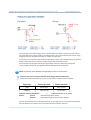
figure Flyport Wi-Fi and Flyport Ethernet
Flyport is a standalone system. It embeds the TCP/IP stack to control the Wi-Fi/Ethernet and it can be
programmed with user-written firmware to accomplish actions as controlling relays, reading digital and analog
IOs, communicating with a UART, I2C or SPI buses, and so on. The PIC24 is a 16 bit, 16 MIPS microcontroller
with 256 KB flash memory and 16 KB of RAM. To be used as a web server (with HTML pages and AJAX
6
Flyport Wi-Fi and Ethernet Programmer's guide framework 2.3 (rev 1.0)
www.openpicus.com
components), Flyport needs only a power supply. Flyport can also send email, and connect with remote TCP
or UDP client/server and much more.
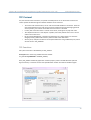
To program the Flyport both the USBNest and miniUSB Programmer can be used, simply connecting them to
the standard USB port of a PC. After installing the drivers, the USBNest and miniUSB Programmer are seen as
a serial port which is used to program the device and to debug the firmware.
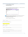
USBNest and miniUSB Programmer
The USBNest is a development system that needs the presence of a PC connected to the USB with
driver installed, or the Flyport will not be turned on. The miniUSB Programmer, instead, can be used for both
PC and stand alone use of the Flyport modules in conjunction of the “NESTs” (expansion boards for rapid
prototyping) or end-products.
Bootloader
Each Flyport module has a serial bootloader preloaded onboard.
QUESTION: What is a serial bootloader and why is it needed on an embedded device as Flyport?
To download a firmware to a microcontroller is usually needed a specific programmer. This is an
external device which writes a new firmware into the flash memory of the microcontroller and
controls the boot and the reset of the device. The programmer is connected to the PC.
To save on this device Flyport has an internal serial bootloader to program the microcontroller using
just a serial connection, for example our low cost miniUSB Programmer.
The bootloader is a small program that starts when the microcontroller boots and listens on the
serial port for a special message. When it receives this special message (usually a string) it
“understand” that the IDE wants to program the micro, so it reads the commands arriving on the
serial port and writes them on the microcontroller memory using an RTSP – real time serial
programming - technique.
QUESTION: The bootloader is located inside the program memory, and it writes inside the program
memory. Can this be dangerous? What happens if the bootloader tries to “overwrite itself”?!
7
Flyport Wi-Fi and Ethernet Programmer's guide framework 2.3 (rev 1.0)
www.openpicus.com
If the PC sends any instruction to write to a “dangerous” memory address, the bootloader stops
writing, avoiding “killing” itself. The IDE gives feedback to the user, saying “the code can damage the
bootloader, so it has not been written it”.
QUESTION: The bootloader is another program resident inside the microcontroller. Will it slow
down the micro? Will it reduce the available memory for the user firmware?
The bootloader runs for a short time only at the startup of the Flyport, so it doesn't slow the Flyport
down in any way. It uses just 1k of memory. So there is no real reduction of the available memory for
application.
NOTE: Flyport uses a customized version of the ds30 bootloader. An opensource and lightweight
bootloader for PIC microcontrollers http://mrmackey.no-ip.org/elektronik/ds30loader/
8
Flyport Wi-Fi and Ethernet Programmer's guide framework 2.3 (rev 1.0)
www.openpicus.com
Pinout
JP1 (connector male 2*13 ways pitch 2.54mm pinheader: SAMTEC TSM-113-01-F-DV )
Pin
Pin Name
Description
(default setting)
1
p1
GPIO
(I2C bus - clock)
Yes
No
2
p2
GPIO
(Digital Input)
Yes
Yes
3
p3
GPIO
(I2C bus - data)
Yes
No
4
p4
GPIO
(Digital Output)
Yes
Yes
5
p5
GPIO
(Digital Input)
Yes
Yes
6
p6
GPIO
(Digital Output)
Yes
Yes
7
p7
GPIO
(Digital Input)
Yes
No
8
p8
GPIO
(SPI bus – clock SCLK)
Yes
Yes
9
p9
GPIO
(Digital Input)
Yes
Yes
10
p10
GPIO
(SPI bus – output SDO)
Yes
Yes
11
p11
GPIO
(Digital Input)
Yes
Yes
12
p12
GPIO
(SPI bus – input SDI)
Yes
Yes
13
p13
UART RX input
Yes
Yes
14
p14
GPIO
Yes
Yes
15
p15
UART TX output
Yes
Yes
16
p16
+5V POWER SUPPLY note 1
-
-
17
p17
GPIO
No
Yes
18
p18
ANALOG INPUT #4 note 2
No
Yes
19
p19
GPIO
No
Yes
20
p20
ANALOG INPUT #3 note 2
No
Yes
21
p21
GPIO
No
No
22
p22
GND GROUND
-
-
No
Yes
-
-
No
Yes
No
No
23
24
p23
p24
(SPI bus – chip select CS)
(Digital Output)
(Digital Output) → Led OUT4
(Digital Output) → Led OUT5
ANALOG INPUT #1
note 2
+3,3V POWER SUPPLY
25
p25
ANALOG INPUT #2
26
p26
RESET (active low)
note 1
note 2
5V Tolerant Remappable
9
Flyport Wi-Fi and Ethernet Programmer's guide framework 2.3 (rev 1.0)
www.openpicus.com
JP2 (Flyport Ethernet Only)
Pin
Pin Name
Description
(default setting)
1
5V Tolerant Remappable
p27
GPIO
(Digital Input)
No
No
2
p28
GPIO
(Digital Input)
No
No
3
p29
GPIO
(Digital Input)
No
No
4
p30
GPIO
(Digital Input)
No
No
5
p31
GPIO
(Digital Input)
No
No
6
p32
GPIO
(Digital Input)
No
No
7
p33
GPIO
(Digital Input)
No
No
8
p34
GPIO
(Digital Input)
No
No
9
-
-
-
10
-
-
-
11
-
-
-
12
-
-
-
13
-
-
-
14
-
-
-
15
-
-
-
16
-
-
-
17
-
Ethernet signal TD-
-
-
18
-
Ethernet signal TD+
-
-
19
-
Ethernet signal TCT
-
-
20
-
Ethernet signal RD+
-
-
21
-
Ethernet signal RCT
-
-
22
-
Ethernet signal RD-
-
-
23
-
RJ45 connector pins 7-8
-
-
24
-
RJ45 connector pins 4-5
-
-
25
-
RJ45 connector LED2
-
-
26
-
RJ45 connector LED1
-
-
NOTE 1. Flyport can be powered at 5V or at 3,3V. If powered on pin 16 then the pin 24 is the output of the internal
LDO. If powered at 3,3V on pin 24 then leave pin 16 not connected.
NOTE 2. Flyport has a precise 2,048V voltage reference onboard for the internal 10 bits ADC. So this is the maximum
value you can apply on Analog Input pins.
NOTE 3. Pin 16,18,20,22,24,26 are directly compatible with the Microchip PICKIT connector.
10
Flyport Wi-Fi and Ethernet Programmer's guide framework 2.3 (rev 1.0)
www.openpicus.com
Hardware functions
This chapter shows how to control the hardware of Flyport: the digital IOs, the analog inputs, how to create
PWM and how to communicate with other devices or peripherals.
QUESTION: Usually, to control the hardware of an embedded device it is required to know specific registers
and how change them. Is this true also for Flyport?
No, the openPicus Framework gives you a set of instructions to control the hardware of Flyport without
needing knowledge of the microcontroller hardware registers.
Digital Inputs and Outputs
Flyport provides lot of Digital Input/output pins to control devices such as Led, Relay, buttons and
more.
Voltage level: The microcontroller works at 3.3V so digital pins are working at 3.3V level.
5V tolerant inputs: some input pins are 5V tolerant, check on the pinout table before connecting!
QUESTION: How are Flyport’s pins named?
When you are writing your application you can refer to the Flyport pin directly: pn, where n is a
number that refers to the corresponding pin number on the Flyport connector.
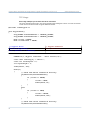
Example:
#include "taskFlyport.h"
void FlyportTask()
{
IOInit(p5,out); //Initialize pin 5 as digital output
IOInit(p6,in); //Initialize pin 5 as digital input
while (1)
{
// MAIN LOOP
}
}
11
Flyport Wi-Fi and Ethernet Programmer's guide framework 2.3 (rev 1.0)
www.openpicus.com
Digital I/Os Functions
First of all initialize the pin as Digital Input or as Digital Output → IOInit(pin name, type);
For example:
Set pin 6 Digital output
→ IOInit(p6, out);
Set pin 5 Digital input
→ IOInit(p5,in);
How to change the state of a Digital Output
For example:
IOPut(p6, on);
IOPut(p6, off);
IOPut(p6, toggle);
→ IOPut(pin name, value);
//sets the pin to high voltage value (3,3V)
//sets the pin to low voltage value (0V)
//toggles the state of the pin (H to L or opposite)
The “on” keyword is associated to a high voltage level, so a “TRUE” logical state. In a similar way the
“off” keyword is associated to a low voltage level, so a “FALSE” logical state.
Note: The keywords “on”, “off”, and “toggle” are case insensitive.
How to read the state of a Digital Input
For example:
IOGet(p5);
→ IOGet(pin name);
//will return the value of pin 5 : on(1) or off(0)
How to enable the internal pull-up or pull-down resistor of a Digital Input
pin 5 digital input with internal pull-up resistor
pin 5 digital input with internal pull-down resistor
→ IOInit(p5, inup);
→ IOInit(p5, indown);
QUESTION: What is the use for pull-up and pull-down resistors in Flyport's input pins?
Pull-up and pull-down resistors are always used to avoid floating voltages on input pins. With a pullup resistor we connect an input pin to a high voltage reference (3.3V), and with a pull-down resistor
we connect the pin to a low voltage reference (ground). Of course you can always change the input
value with another voltage source, or with a switch, as shown in the figure below:
12
Flyport Wi-Fi and Ethernet Programmer's guide framework 2.3 (rev 1.0)
www.openpicus.com
In the pull-down circuit of the figure, we can see that when the switch is opened (no other sources
are connected), the input pin “reads” a low voltage value. If we close the switch (and connect a high
voltage source), we change the what the pin “reads” to a high value.
In the pull-up case, we have a high value when the switch is open, and a low value when the switch is
closed, because the internal reference is high and the external reference is low.
The convenience of using the internal pull-up/pull-down resistors is that they are inside the
microcontroller, and you can change them without adding external components.
NOTE: Pay attention of the different pull-up/pull-down values on switch states!
QUESTION: How can we catch a pushbutton state change? Pressed or Released?
Buttons need always internal pull-up (“inup”) or pull-down (“indown”) resistors enabled.
Input type
Button pressed
Button released
inup
ON to OFF
OFF to ON
indown
OFF to ON
ON to OFF
Check the state of a pushbutton
→
IOButtonState(pin name)
Returns:
pressed
if the button has been pressed
released
if the button has been not pressed or released
You don't have to keep track of the state of the pin, or of its logical value. The openPicus framework
does this work for you and tells you if the button has been pressed or released.
13
Flyport Wi-Fi and Ethernet Programmer's guide framework 2.3 (rev 1.0)
www.openpicus.com
Example:
if(IOButtonState (p5) == pressed)
{
// Code to do when p5 is pressed...
}
else
{
// Code to do when p5 is not pressed...
}
To know what kind of value you have to substitute instead of pressed in the above example, check
the table above. In the case of an “inup” resistor substitute “OFF” (that is a low voltage level). In the
case of an “indown” resistor substitute “ON” (that is a high voltage level).
A frequent problem related to buttons and switches is bouncing of the signal.
This problem is generated by mechanical issues with the internal contacts of buttons and switches
but with a small amount of software, problems with bounce can be solved.
The IOButtonState has an integrated de-bounce feature, so you don't have to worry about this
problem.
The results will be filtered with a 20ms filter:
• if the input value changes in less than 20ms, the result will not be valid
• if the input value remains the same over20ms, the result will be valid
14
Flyport Wi-Fi and Ethernet Programmer's guide framework 2.3 (rev 1.0)
www.openpicus.com
Remappable Pins
A great feature of Flyport module is the possibility of remap the peripheral to almost any pin.
As you can see in the pinout table, almost each pin is remappable.
Pin remapping allows you to add more UARTs, PWMs, SPIs, TIMER and External interrupts.
For PWMs you can use the PWM dedicated functions (see PWM section). For the other peripheral
the list below shows the functionalities you can associate to every pin.
QUESTION: What are the various assignable Functionalities at Remappable Pins? What are their
name?
Output peripherals
–
UART1TX
–
UART1RTS (not enabled in default UART initialization)
–
UART2TX
–
UART2RTS (not enabled in default UART initialization)
–
UART3TX
–
UART3RTS (not enabled in default UART initialization)
–
UART4TX
–
UART4RTS (not enabled in default UART initialization)
–
SPICLKOUT (for SPI Master mode, Clock Output Signal)
–
SPI_OUT (Data Output Signal)
–
SPI_SS_OUT (for SPI Master mode, Slave Select Signal)
Input peripherals
–
UART1RX
–
UART1CTS (not enabled in default UART initialization)
–
UART2RX
–
UART2CTS (not enabled in default UART initialization)
–
UART3RX
–
UART3CTS (not enabled in default UART initialization)
–
UART4RX
–
UART4CTS (not enabled in default UART initialization)
–
EXT_INT2
–
EXT_INT3
–
EXT_INT4
–
SPICLKIN (for SPI Slave mode, Clock Input Signal)
–
SPI_IN (Data Input Signal)
–
SPI_SS (for SPI Slave mode, Slave Select Signal)
–
TIM_4_CLK
With the Flyport module pinstrip connector more expansions with different pinouts can be created
just by using the remapping feature. As a result the layouts of Flyport expansion boards can simpler
and easier to route on PCBs, breadboards or any prototyping board type.
15
Flyport Wi-Fi and Ethernet Programmer's guide framework 2.3 (rev 1.0)
www.openpicus.com
The pin configuration depends on your specific application, so the “Hardware Architecture” should
be decided first: which pins will be used as peripherals, and which pins will be “simple I/Os”
Remappable Pins Functions
To REMAP a pin you can simply use the IOInit function. The difference between the digital I/Os and
PeripheralPinSelect assignment is done with different values of the second parameter:
IOInit ( p2, EXT_INT3 ); will associate the pin 2 of Flyport to the External Interrupt 3 functions.
IOInit ( p18, SPI_OUT); will associate the pin 18 of Flyport to the SPI2 data out functionality.
Note: Remapping is useful but you need to pay attention. If a pin is assigned to a peripheral, the
IOGet and IOPut will not work properly. Secondly, after the assignment, a new function will be
associated to a pin, and it must be used the related peripheral functions to set up the peripheral
module.
For example UART2 and UART3 are not enabled by default to give more memory to the user
application. If you need to use 3 UARTs in your application, you must enable these 3 UARTs using the
Wizard inside the IDE. See the UART section for more information.
QUESTION: Can I use the remapping feature at runtime?
Yes, the openPicus Framework supports pin remapping at runtime.
We suggest to plan a definitive pin mapping and don't change during the development. Remember
that an error with remapping may cause hardware fault.
Example: remap the UART2 on pin 2 and 4
#include "taskFlyport.h"
void FlyportTask()
{
// First of all: REMAP THE PINS
IOInit(p2,UART2RX); // Remap p2 pin as UART2RX
IOInit(p4,UART2TX); // Remap p4 pin as UART2TX
//After Remapping enable the module...(see UART chapter...)
while (1)
{
// MAIN LOOP
}
}
16
Flyport Wi-Fi and Ethernet Programmer's guide framework 2.3 (rev 1.0)
www.openpicus.com
Analog Inputs
Flyport has several analog channels connected to the internal 10bit ADC of the microcontroller.
QUESTION: What is the relation between number and voltage?
Flyport has a precise Voltage reference inside at 2.048V. This means that the max voltage on an
analog input is 2.048V.
The ADC is 10 bit. So it means 2^10 = 1024 different values (0-min voltage to 1023-max voltage).
Since the ADC uses the internal precise voltage reference of the module the single bit value is
2.048/1024=2mV
For example and Analog Read value of 1000 means:
1000 * 0.002 V = 2V of voltage on the analog input
Note: Analog input pins may be used also as GPIO, but they are not 5V tolerant! Avoid to apply a
voltage > 3.3V or you could damage the microcontroller!
QUESTION: How can I test this feature?
Here is a simple connection of a potentiometer to test analog input 1:
As you can see from schematics, there is a resistor of 680 Ohm and a potentiometer of 1KOhm. This
configuration is made to reduce the max voltage of the Analog input pin. In fact, when the
potentiometer reaches its max value on the analog pin we have:
Va1_in = Vdd * (R1 / R1+R2) = 3.3 * (1000 * 1680) = 1.96V
This value is compatible with the voltage input range of analog inputs (max 2.048V)
17
Flyport Wi-Fi and Ethernet Programmer's guide framework 2.3 (rev 1.0)
www.openpicus.com
Analog Inputs Functions
Read an Analog Input
→
ADCVal(channel);
This function returns an int value (from 0 to 1023...) related to the Analog channel (from 1 to 4) as
reported on the pinout table.
Parameters:
channel: specify the ADC input channel (1 to 4)
Example:
int myADCValue;
//Initialize the variable to get the value
myADCValue = ADCVal(1); //Returns the value of the Analog channel #1
18
Flyport Wi-Fi and Ethernet Programmer's guide framework 2.3 (rev 1.0)
www.openpicus.com
PWMs
Flyport provides up to 9 PWMs using remappable pin function.
QUESTION: What is a PWM signal?
PWM, Pulse Width Modulation, is a digital periodic signal. It is like a square wave, but the duty cycle
is variable. The duty cycle is the ratio between the high level period duration and the low level period
duration, often expressed in %.
A duty cycle of 100% is a signal that is always high, a duty cycle of 0% is always low, and 50% is a
perfect square wave where the high and low durations are the same.
There are 2 main parameters of a PWM signal: the duty cycle discussed above, and the frequency of
the signal, which represents the repetitions per second of our signal.
For example, a PWM with a frequency of 200Hz will have the period:
T = 1/f = 1/200 = 5ms
So every 5ms the period will be repeated. Using a PWM with 25% of duty there will be:
•
•
•
Total period: 5ms
High duration: (5ms*25/100) = 1.25 ms
Low duration: 5ms – 1.25ms = 3.75 ms
QUESTION: How can I use PWM signals?
Normally PWM signal is used to drive a Led or a DC motor. It's possible also to create “virtual” analog
output signal. Note that PWM is not a DAC (digital to analog converter), but a simple way to generate
an analog signal adding some R-C filtering. The R-C filter design is a relatively complex operation that
depends on the frequency of the PWM and on the load at the output pin.
19
Flyport Wi-Fi and Ethernet Programmer's guide framework 2.3 (rev 1.0)
www.openpicus.com
PWM function
There are 4 basic PWM functions:
Initialize the pin as PWM
→PWMInit(BYTE pwm, float freq, float dutyc);
It is a mandatory to call the initialize function to setup the a PWM module
Parameters:
pwm: PWM id (from 1 up to 9)
freq:
the frequency of the PWM signal in Hertz
duty: new duty cycle desired (from 0 up to 100, it is expressed in percentage)
Activate a PWM signal
→PWMOn(Byte io, BYTE pwm);
Parameters:
io:
io pin to assign at pwm functionality (p1, p2, p3...)
pwm: PWM id (from 1 up to 9)
Change Duty Cycle
→PWMDuty(float duty, Byte pwm);
This function can be used to change the pwm duty cycle “on the fly”.
Parameters:
duty: new duty cycle desired (from 0 up to 100, it is expressed in percentage)
pwm: PWM id (from 1 up to 9)
To Turn Off the PWM
→PWMOff(BYTE pwm);
This function can be used to turn off a PWM.
Parameters:
pwm: PWM id (from 1 up to 9)
A simple application of PWM can be changing the brightness of a LED. In fact, by changing the PWM
duty cycle we change the root mean square (RMS) voltage of the signal, so we can change the
brightness of a LED with PWM.
For example:
PWMInit(1, 1000, 100); //Initialize PWM1 to work
//at 1000 Hz, 100% of duty (always on)
PWMOn(p5, 1);
//Turns on PWM1, and set it to p5
PWMDuty(50, 1);
//Change the duty at 50% (about half bright)
PWMDuty(0,1);
//Change the duty at 0% (off)
PWMOff(1);
20
Flyport Wi-Fi and Ethernet Programmer's guide framework 2.3 (rev 1.0)
www.openpicus.com
A more complex example (to add on taskFlyport.c):
#include “taskFlyport.h”
void FlyportTask()
{
const int maxBright = 37;
//here we set max % of brightness
const int minBright = 2;
//and here the min %
float bright = (float)maxBright;
PWMInit(1,1000,maxBright);
PWMOn(p5, 1);
while(1)
{
for (bright = maxBright; bright >
{
PWMDuty(bright, 1);
vTaskDelay(1);
//used to
}
for (bright = minBright; bright <
{
PWMDuty(bright, 1);
vTaskDelay(1);
//used to
}
}
minBright; bright--)
slow down the effect
maxBright; bright ++)
slow down the effect
}
For more information about PWM and its application:
http://en.wikipedia.org/wiki/Pulse-width_modulation
21
Flyport Wi-Fi and Ethernet Programmer's guide framework 2.3 (rev 1.0)
www.openpicus.com
Serial Communication (UART)
The UART is a serial asynchronous communication module to communicate with an external device
such as a GPS receiver.
You must know the baud rate of the signal or the UART will not be able to work properly.
Flyport has a UART input buffer of 256 characters that stores the incoming chars. You don't have to
poll the UART buffer, but just check the number of received chars.
The size of the UART input buffer is customizable by the user, using the Wizard tool inside the IDE:
Warning: the maximum memory used by UART buffers should not exceed 6144. The Wizard tool will
show the effects of UART buffer size on total memory available.
To perform testing on UART we suggest PC programs like “Putty”, “Termite” or the IDE Serial Monitor.
Do not use Hyper Terminal because it does not support the DTR signal (that is used by miniUSB
programmer as Reset signal).
22
Flyport Wi-Fi and Ethernet Programmer's guide framework 2.3 (rev 1.0)
www.openpicus.com
UART Functions
First of all you must initiate the UART at a specific baudrate. Then you must enable the UART.
Note: In the IDE wizard, there is the possibility to use the uart 1 as “TCP debug on UART1”. In this
case the UART1 module is initialized at 19200 baud and turned on at startup.
Initialize the UART
→UARTInit(int port, long int baud);
This is a mandatory function that initializes the module to work properly.
This function is called in the Flyport Framework initialization, but it can be recalled to change the
baudrate parameter at runtime.
Parameters:
port:
The UART port to initialize (from 1 to 3)
baud: Desired baudrate
Turn On the UART
→UARTOn(int port);
This function turns on the UART module functionalities. It should be called only after UARTInit
Parameters:
port:
the UART port to turn on
Turn Off the UART
→UARTOff(int port);
This function turns off the UART module functionalities. It should be called before calling UARTInit.
Parameters:
port:
the UART port to turn off
Check the UART input buffer
→UARTBufferSize(int port);
This function returns an int number equal to how many chars have arrived and are stored inside the
UART RX Buffer.
Parameters:
port:
the UART port
Returns:
int N: number of chars inside the buffer
Read the UART input buffer
→UARTRead(int port, char *towrite,
int count);
This function reads characters from the UART RX buffer and puts them in the char pointer “towrite”.
It also returns the report of the operation.
Parameters:
port:
the UART port
towrite: the char pointer to fill with the read characters
count: the number of characters to read
Returns:
int N: N > 0, N characters correctly read.
N < 0, N characters read, but buffer overflow detected.
23
Flyport Wi-Fi and Ethernet Programmer's guide framework 2.3 (rev 1.0)
www.openpicus.com
Send a string to the UART
→UARTWrite(int port, char *buffer);
This function writes the specific string on the UART port.
Parameters:
port:
the UART port
buffer the string to write (a NULL terminated char array)
Send a char to the UART
→UARTWriteCh(int port, char chr);
This function writes a specific char to the UART port.
Parameters:
port:
the UART port
chr
the character to write
Flush the UART input buffer
→UARTFlush(int port);
This function clears the buffer of the specified UART port.
Parameters:
port:
the UART port
24
Flyport Wi-Fi and Ethernet Programmer's guide framework 2.3 (rev 1.0)
www.openpicus.com
I2C Communication Protocol
I2C is a 2 wire serial communication widely used in embedded electronics to connect devices such as
external memory and more.
Unlike the UART, I2C has a Master-Slave architecture, where the Master starts all the requests of
communication. The baud rate is given by the Master, and the most used values are 100kb/s (low
speed) and 400kb/s (high speed).
I2C bus needs pull-up resistors and dedicated open collector pins.
To use the I2C protocol has s a determined sequence of operations for starting, stopping, write, read
and checking if the data was transmitted ok.
For more information see the link:
http://en.wikipedia.org/wiki/I%C2%B2C
OpenPicus framework offers some functions to easily manage the I2C communication, using Flyport
as a Master. In this way it’s possible to communicate with I2C slave devices and read/write their
register. It’ possible to attach more than one device on the bus, since I2C uses addressing. The only
issue is to check that any device connected on the bus must have a different address.
I2C Basic Functions
Initialize I2C
→ I2CInit(BYTE speed);
This function initializes the I2C at the specified speed of communication.
Parameters:
speed: it can be HIGH_SPEED (400K) or LOW_SPEED (100K)
Send a Start condition
→ I2CStart();
This function sends a start sequence on the I2C bus.
Parameters:
none
Send a Restart condition
→ I2CRestart();
This function resends a start sequence on the I2C bus.
Parameters:
none
Send a Stop condition
→ I2CStop();
This function sends a stop sequence on the I2C bus.
Parameters:
none
25
Flyport Wi-Fi and Ethernet Programmer's guide framework 2.3 (rev 1.0)
www.openpicus.com
Write a byte on I2C
→ I2CWrite(BYTE data);
This function writes a byte of data .
Parameters:
data: The byte data to be sent
Returns:
0:
NACK condition detected
1:
ACK condition detected
2:
Write Collision detected
3:
Master Collision detected
Accessing memory registers of slave devices
The easier way to communicate with a I2C device, is using the ready-to-go functions offered by the
OpenPicus Framework to read/write registers. Using the following functions, you don't need to know
the details of the I2C communications, you are just requested to pass the device and the register(s)
addresses and the commands will exchange the data with the slave device. The functions follows the
standard way to read/write registers on I2C bus, if you experience any problems, always refer to slave
device datasheet to check if some particular operation is required to communicate.
Note on device addressing: in the following functions, with "device address" is intended the 7-bit I2C
address of the device. You can find the default address and how to change it in the datasheet of each
I2C device. The address will be correctly shifted and added with the read/write bit by the read/write
functions
Read a single register
→ I2CReadReg( BYTE DeviceAddr,
BYTE RegisterAddr,
unsigned int rwDelay);
This function to read a byte of data from a specific device.
Parameters:
DeviceAddr:
The byte address of slave device
RegisterAddr:
The byte address of memory register to read
rwDelay:
The delay (expressed in 10us) between write and read operations
performed. This delay is needed by some I2C devices (please see slave
datasheet
for further info)
Returns:
char of data read.
Reading mulLple registers → I2CReadMulti(
BYTE DeviceAddr,
BYTE RegisterAddr,
BYTE destination[],
unsigned int numReg,
unsigned int rwDelay);
This function to read a “numReg” amount of bytes starting from a specific address.
Parameters:
DeviceAddr:
The byte address of slave device
RegisterAddr:
The byte address of memory register to read
destination:
The byte array to store data
numReg:
The amount of register to read.
26
Flyport Wi-Fi and Ethernet Programmer's guide framework 2.3 (rev 1.0)
rwDelay:
www.openpicus.com
The delay (expressed in 10us) between write and read operations
performed. This delay is needed by some I2C devices (please see slave datasheet
for further info)
Returns:
BOOL result of operaXon: TRUE → operaXon success, FALSE → operaXon failed
Write a single register
→ I2CWriteReg( BYTE DeviceAddr,
BYTE RegisterAddr,
BYTE valueToWrite);
This function writes a byte of data to specific device.
Parameters:
DeviceAddr:
The byte address of slave device
RegisterAddr:
The byte address of memory register to write
valueToWrite: The new value to put inside memory register
Returns:
None
Reading mulLple registers → I2CWriteMulti( BYTE DeviceAddr,
BYTE RegisterAddr,
BYTE dataSource[],
unsigned int numReg);
This function to read a byte of data from a specific device.
Parameters:
DeviceAddr:
The byte address of slave device
RegisterAddr:
The byte address of memory register to write
destination:
The byte array of data to write
numReg:
The amount of register to write.
Returns:
BOOL result of operaXon: TRUE → operaXon success, FALSE → operaXon failed
Note: more examples of I2C functions usage are available at wiki.openpicus.com
27
Flyport Wi-Fi and Ethernet Programmer's guide framework 2.3 (rev 1.0)
www.openpicus.com
RTCC module
RTCC – Real Time Clock Calendar – is a hardware clock module embedded on Flyport. It provides
automatic clock counter and customizable interrupt driven alarm.
Using openPicus framework libraries it's possible to read and write values of RTCC (date and time)
and set an alarm. Alarm event can be both assigned to a callback function, or read in a dedicated
status function.
RTCC APIs
Initialize/Write RTCC module
→ void RTCCSet(struct tm* rtcc);
This function sets the date/time and enables RTCC module.
Parameters:
rtcc:
a pointer to a struct tm variable, containing the date and the time to set
Read RTCC module
→ void RTCCGet(struct tm* rtcc);
This function reads the actual date/time from the RTCC and put it inside a struct pointer
Parameters:
rtcc:
a pointer to a struct tm variable to fill with data
Configure Alarm of RTCC module → void RTCCAlarmConf(
struct tm* rtcc,
int repeats,
BYTE whenToRaise,
void (*fptr)());
This function reads the actual date/time from the RTCC and put it inside a struct pointer
Parameters:
rtcc:
a pointer to a struct tm variable to fill with data
repeats: specifies how many times the alarm must be repeated:
REPEAT_NO alarm must not be repeated
1 – 256 the number of times alarm must be repeated
REPEAT_INFINITE alarm must be repeated forever
whenToRaise:
how often alarm should be raised
EVERY_HALF_SEC alarm is raised every half second
EVERY_SEC alarm is raised every second
EVERY_TEN_SEC alarm is raised every 10 seconds
EVERY_MIN alarm is raised every minute
EVERY_TEN_MIN alarm is raised every 10 minutes
EVERY_HOUR alarm is raised every hour
EVERY_DAY alarm is raised every day
EVERY_WEEK alarm is raised every week
EVERY_MONTH alarm is raised every month
EVERY_YEAR alarm is raised every year
fptr:
custom function to execute when alarm event is raised. Use NO_ALRM_EVENT to ignore.
28
Flyport Wi-Fi and Ethernet Programmer's guide framework 2.3 (rev 1.0)
www.openpicus.com
Reads Alarm status of RTCC module → BOOL RTCCAlarmStat();
Returns the actual status of alarm event. This function can be polled continuously to get alarm
trigger.
Returns:
BOOL status of alarm:
TRUE → Alarm was triggered. The funcXon is automaXcally set to FALSE unXl next alarm.
FALSE → No alarm event.
Enable/Disables Alarm of RTCC module → void RTCCAlarmSet(BYTE run);
Activates or deactivates the alarm
Parameters:
run:
TRUE → Alarm acXvated.
FALSE → Alarm not acXvated.
29
Flyport Wi-Fi and Ethernet Programmer's guide framework 2.3 (rev 1.0)
www.openpicus.com
Using the TCP/IP Stack
Flyport TCP/IP management is based on the Microchip TCP/IP stack. On that basis, the openPicus framework
integrates the stack with the operating system FreeRTOS, to ease the management of any TCP/IP operation.
Even if all the communication issues have been simplified to make everything easier, the TCP/IP is a very
complex stack with many functionalities, so a minimum knowledge of the TCP/IP is needed. (If you are not
able to make a basic configuration of an access point, of a wireless router, you may experience problems in
the integration of Wi-Fi with your application).
Managing the Network
Flyport Wi-Fi
IMPORTANT: Flyport Wi-Fi cannot work as access point. In ad-hoc mode, DHCP server of Flyport
assigns the IP address only to one device. Ad-hoc networks are peer-to-peer networks. In
infrastructure mode, Flyport Wi-Fi connects to already existing networks.
How to manage all the aspects of the network, how to monitor the status of the connections and
how to modify all the parameters of the Ethernet and Wi-Fi.
The Connection Profiles
Flyport allows the user to freely set any parameter for a Network connection (like IP and MAC
address, Subnet mask, Gateway, DNS, Host Name, DHCP...) but also for Wi-Fi connection (SSID,
encryption and so on). All the configuration parameters can be set using the IDE TCP/IP wizard and
that configuration will be stored in the “ETH_DEFAULT” connection profile for Flyport Ethernet, or
“WF_DEFAULT” connection profile for Flyport Wi-Fi.
In the openPicus Framework there are two Connection Profiles, the default profile named
ETH_DEFAULT/WF_DEFAULT and the customizable one named ETH_CUSTOM/WF_CUSTOM.
30
Flyport Wi-Fi and Ethernet Programmer's guide framework 2.3 (rev 1.0)
www.openpicus.com
QUESTION: What are the profiles?
The profiles are structures which store basic Ethernet/Wi-Fi information, necessary for
Flyport to know how to connect to the network. The basic information are:
–
–
–
–
–
–
IP of the Flyport
DNS servers
Default GATEWAY
DHCP enable / disable
NETBIOS name
SSID name (Wi-Fi only)
–
–
Network type (ad-hoc or infrastructure) (Wi-Fi only)
Security configuration parameters ( type and password) (Wi-Fi only)
QUESTION: How can the profiles be used?
Flyport Wi-Fi
The profiles can be used inside the function that starts a Wi-Fi connection. This connection
function is
WFConnect( connection profile);
and can be used with “WFConnect(WF_DEFAULT);” or with “WFConnect(WF_CUSTOM);”
Flyport Ethernet
The profiles can be used with the function that restarts the connection.
ETHRestart( connection profile);
and can be used with “ETHRestart(ETH_DEFAULT);” or with “ETHRestart(ETH_CUSTOM);”
QUESTION: How can I customize the profiles?
There are two ways to customize a connection profile.
The WF_DEFAULT/ETH_DEFAULT is the standard profile, and this type of connection is used
by the Framework in the standard template. Its parameters can be changed with the Wizard
tool of the IDE. Those values are fixed in PIC memory and can't be changed at runtime. Every
time you change some parameters in the Wizard you must compile the firmware again, and
download it inside the Flyport.
The WF_CUSTOM/ETH_CUSTOM is the runtime configurable profile template. Its
parameters can be updated in the Flyport tasks, but all the changes will be erased after a
Flyport reboot! In fact, WF_CUSTOM/ETH_CUSTOM are the same of
WF_DEFAULT/ETH_DEFAULT at startup, so every change should be reloaded by user
application. Every time Flyport is restarted, the CUSTOM profile should be loaded from
memory, and before a restart the values should be saved in memory by the user.
31
Flyport Wi-Fi and Ethernet Programmer's guide framework 2.3 (rev 1.0)
www.openpicus.com
Flyport Ethernet
Ethernet Connection Functions
To handle the ethernet connections the framework supports the user variable MACLinked.
MACLinked reflects the state of the ethernet cable connection:
BOOL MACLinked =
• TRUE → the Ethernet Cable is connected (at a access point or at a PC or other
device in a point-to-point connection)
• FALSE → the Ethernet Cable is unconnected, or the connecXon is not working (for
example the other device is not responding or turned of)
Flyport Wi-Fi
Wi-Fi Connection Functions
To handle the Wi-Fi connections the framework supports some user functions. Some of them are
usable to set the connection profile, the others to use those profiles to establish the just set up
connection. To help user with the settings, there is a graphical wizard in openPicus IDE, but you could
change this parameters with a simple text editor; we suggest you to use the Wizard, since it is a easy
and fast tool, and it compiles project modification automatically after changes.
32
Flyport Wi-Fi and Ethernet Programmer's guide framework 2.3 (rev 1.0)
www.openpicus.com
For more info about the IDE Wizard please refer to the openPicus IDE Manual.
QUESTION: How can I check Wi-Fi connection?
Actually there is a very important variable called WFStatus. Its value is directly dependent on Wi-Fi
connection status, and can be (them are defined in Hwlib.h):
•
•
•
•
•
•
•
NOT_CONNECTED
CONNECTING
CONNECTED
CONNECTION_LOST
CONNECTION_FAILED
STOPPING
TURNED_OFF
Those values defines different statuses, and different “jobs in progress”.
The status “NOT_CONNECTED” and “TURNED_OFF” are static status, and they can be changed only
with a user task input. “NOT_CONNECTED” occurs when a Wi-Fi connection is closed and there is no
need to open it. The “TURNED_OFF” status occurs when Wi-Fi module is turned off for power saving.
The other status items are dynamic and can change without user input, but by external events. In
fact,when a user tries to connect to a Wi-Fi network, the WFStatus changes from “NOT_CONNECTED”
to “CONNECTING”. This status shows that the Wi-Fi module is trying to connect to a network. If it
connects, WFStatus changes to “CONNECTED”; if it fails, it changes to “CONNECTION_FAILED”. If this
last status occurs the openPicus Framework automatically retries to connect to Wi-Fi network until
success is reached or the user stops the connection from the user task. If a connection is lost due to
network problems (for example no reply from router, or too much distance between Flyport and the
Wi-Fi device communicating with Flyport) the WFStatus becomes “CONNECTION_LOST” and the
Framework automatically retries to connect Flyport to the network.
33
Flyport Wi-Fi and Ethernet Programmer's guide framework 2.3 (rev 1.0)
www.openpicus.com
These values of the WFStatus variable can be used in the user task, for example, to control the Wi-Fi
connection or to stop the retries for a while after reaching a retry limit.
To Connect to a Wi-Fi net
→
WFConnect( int pconn );
The WFConnect() function starts opening a connection using the provided Wi-Fi profile. The Flyport
will continue its tasks even if it can't connect to the network, and will send UART messages regarding
connection time-out.
Parameters:
pconn: the Connection Wi-Fi Profile (WF_DEFAULT or WF_CUSTOM)
To Disconnect from a Wi-Fi net
→
WFDisconnect();
This function starts the closing of the actual network
Parameters:
none
To Stop Connection retries to a Wi-Fi net
→
WFStopConnecting( );
When the WFConnect command is launched, the device tries to connect to the selected Wi-Fi
network until it doesn't find it. If it is necessary to STOP retrying, this function must be called.
Parameters:
pconn: the Connection Wi-Fi Profile (WF_DEFAULT or WF_CUSTOM)
34
Flyport Wi-Fi and Ethernet Programmer's guide framework 2.3 (rev 1.0)
www.openpicus.com
QUESTION: How can I know what kind of connection profile I have used?
The WFConnection variable stores the Wi-Fi profile number used to connect Flyport to the Wi-Fi
network. The “if(WFConnection == WF_CUSTOM)” can be used to find out if a Wi-Fi custom profile
has been used.
Customizing Network Parameters at Runtime
The Framework supports several user functions which may be used to Customize the
ETH_CUSTOM/WF_CUSTOM profile. Some are used to set parameters, others for saving, loading and
checking profiles, one is for Flyport Wi-Fi only.
To Set a parameter of ETH/WF_CUSTOM →
NETSetParam(int paramtoset,
char * paramstring );
Parameters:
paramtoset:
the parameter of profile to change.
–
MY_IP_ADDR
–
PRIMARY_DNS
–
SECONDARY_DNS
–
MY_GATEWAY
–
SUBNET_MASK
–
NETBIOS_NAME
–
DHCP_ENABLE (ENABLED or DISABLED)
–
SSID_NAME
(Wi-Fi only)
–
NETWORK_TYPE (ADHOC or INFRASTRUCTURE)
paramstring:
the string value of parameter.
(Wi-Fi only)
Flyport Wi-Fi
To Set the Security Parameters of WF_CUSTOM → WFSetSecurity(BYTE mode,
char* keypass,
BYTE keylen,
BYTE keyind);
Parameters:
mode: the security mode. Following are valid parameters:
–
WF_SECURITY_OPEN : no security
–
WF_SECURITY_WEP_40: WEP security, with 40 bit key
–
WF_SECURITY_WEP_104: WEP security , with 104 bit key
–
WF_SECURITY_WPA_WITH_KEY: WPA-PSK personal security, the user specifies the hex key
–
WF_SECURITY_WPA_WITH_PASS_PHRASE: WPA-PSK personal security, the user specifies
only the passphrase
–
WF_SECURITY_WPA2_WITH_KEY: WAP2-PSK personal security, the user specifies the hex
key
–
WF_SECURITY_WPA2_WITH_PASS_PHRASE: WPA2-PSK personal security, the user specifies
only the passphrase
–
WF_SECURITY_WPA_AUTO_WITH_KEY: WPA-PSK personal or WPA2-PSK personal (the
Flyport will auto select the mode) with hex key
–
WF_SECURITY_WPA_AUTO_WITH_PASS_PHRASE: WPA-PSK personal or WPA2-PSK
personal (autoselect) with pass phrase
35
Flyport Wi-Fi and Ethernet Programmer's guide framework 2.3 (rev 1.0)
www.openpicus.com
keypass: the key or passphrase fot the network A key must be specified also for open connections
(you can put a blank string, like “”).
keylenght:lenght of the key/passphrase. Must be specified also for open connections (can be 0).
keyind: index of the key (used for WEP security, but must be specified also for all others, in that case
can be 0).
NOTE: For WPA/WPA2 with passphrase, the Flyport must calculate the hex key. The calculation is long
and difficult, so it will take about 20 seconds to connect!
To Save parameter of ETH/WF_CUSTOM
→
NETCustomSave( );
To prevent losing all the data in a custom profile (normally stored in RAM), this function is
used to store all the values in internal non volatile Flash memory. The saved parameters should be
loaded after every reboot of Flyport.
To Load parameter of ETH/WF_CUSTOM
→
NETCustomLoad( );
Load the previously saved parameters of WF_CUSTOM.
To Detect existing saved parameter of ETH/WF_CUSTOM
→
NETCustomExist( );
Verifies if data is present in flash memory for the WF_CUSTOM profile. It can be useful at the
startup of the device to check if in a previous session (before any power off) the configuration data
was saved. If so, the firmware can choose if the Custom Parameters should be loaded from flash
memory.
To Delete existing saved parameter of ETH/WF_CUSTOM
36
→
NETCustomDelete( );
Flyport Wi-Fi and Ethernet Programmer's guide framework 2.3 (rev 1.0)
www.openpicus.com
Network Functions and Variables
There are more functions and system variables to control the Wi-Fi state and use the Hibernation
mode:
AppConfig is a variable which contains many network parameters. It is an APP_CONFIG struct type.
The majority of parameters are found in ETH_DEFAULT/WF_DEFAULT and in
ETH_DEFAULT/WF_CUSTOM, but the IP address of Flyport can change from its default value if DHCP
is enabled.
To access to this specific parameter, the notation AppConfig.MyIPAddr is used. This will return the
IP_ADDR variable that stores the effective value of Flyport's IP address, even if it was changed by
other devices.
To use the AppConfig.MyIPAddr values as four different bytes:
• AppConfig.MyIPAddr.byte.LB
• AppConfig.MyIPAddr.byte.HB
• AppConfig.MyIPAddr.byte.UB
• AppConfig.MyIPAddr.byte.MB
In “Helpers.c” there is also a function to convert a generic string to IP_ADDR variable.
Its statement is:
BOOL StringToIPAddress( BYTE* str, IP_ADDR* IPAddress);
This function returns TRUE if the string provided were converted to IP Address, or FALSE if the
process was concluded unsuccessfully.
To use the AppConfig.MyIPAddr byte values as a single string format, them can be converted using
the helper function
void IPAddressToString(IP_ADDR* IPAddress, char* ipString);
Flyport Wi-Fi
tWFNetwork is a structure that contains all the network parameters:
•
•
•
•
•
•
•
•
BYTE bssid [WF_BSSID_LENGTH]
CHAR ssid [WF_MAX_SSID_LENGTH+1]
UINT8 channel
UINT8 signal
BYTE security
BYTE type
UINT8 beacon
UINT8 preamble
37
Flyport Wi-Fi and Ethernet Programmer's guide framework 2.3 (rev 1.0)
www.openpicus.com
WFScan() is a utility function to start scanning for all the available Wi-Fi networks.
Each of the Wi-Fi networks found will be indexed with an int number.
Note: this function cannot be called inside “WF_Event.c”!
WFNetworkFound() returns an int number of how many networks are found. At startup it returns 0.
This function is useful to know the maximum number of networks found, 0 for no Wi-Fi networks
found yet.
WFScanList(int n) reads the parameters of the discovered network number n and returns a
tWFNetwork variable, with all the parameters read.
Below is an example of the use of this function:
tWFNetwork NetData;
int indexNetwork = 1;
NetData = WFScanList( indexNetwork );
UARTWrite(1, NetData.ssid);
NOTE: for more information on using the Network Scanner Functions, please refer to “APP –
NetworkScanner” in the download section of www.openpicus.com
In case the application uses DHCP Client (so it is enabled inside the Wizard, and also in network
parameters), the IP address of the Flyport module may change. To know if the DHCP of the
router/access point has assigned a IP address to the Flyport, it can be monitored the variable
DHCPAssigned.
The BOOL DHCPAssigned value is:
38
•
FALSE
→
the IP is not assigned
•
TRUE
→
the IP is assigned
Flyport Wi-Fi and Ethernet Programmer's guide framework 2.3 (rev 1.0)
www.openpicus.com
TCP Protocol
TCP, Transmission Control Protocol, is a packet oriented protocol. It can be used to transmit and
receive packets of data through the network between server and client.
•
•
•
•
•
To use this kind of transmission, server and client should establish a connection. Since the
connection between server and client consumes network resources (exchanging protocol
service packets), it should be closed after the transmission is finished.
In every TCP connection there is a Server and a Client, and Flyport can play both roles.
The TCP/IP transmission is “full-duplex” capable, and all the packets sent arrive in source
order and “at most once”.
By using acknowledgement, timeouts and checksums, the TCP protocol can check the
integrity of every packet and know if a packet arrived at the destination.
At every host, multiple connections can be opened with the using of different ports, which
we will call the “TCP_SOCKETS”.
TCP Functions
Every TCP connection is identified by its TCP_SOCKET.
First of all one or more TCP_SOCKETs must be created:
TCP_SOCKET myTCPSocket = INVALID_SOCKET;
Every TCP_SOCKET needed by application must be properly sized in the IDE Wizard to optimize
Flyport memory. It is best to use the least possible both number of sockets and buffer lengths.
39
Flyport Wi-Fi and Ethernet Programmer's guide framework 2.3 (rev 1.0)
www.openpicus.com
The parameters to set are the same for “GENERIC_TCP_CLIENT” and for “GENERIC_TCP_SERVER”.
Them are:
•
Count: the number of Socket for connection to use; them can be different from client and
server
•
•
TX Buffer: the maximum dimension of transmission buffer
RX Buffer: the maximum dimension of receive buffer
The total TCP socket memory is the maximum space that can be used for TCP sockets inside the Wi-Fi
module's memory. The TCP buffers are not stored in microcontroller's memory but in the Wi-Fi
module's memory, so using TCP sockets does not affect PIC memory usage. A maximum of 8100
bytes can be used. This is the sum of all TCP sockets that are listed in the “Currently Defined Sockets”
list.
The “GENERIC_TCP_XXXXXX” TX and RX Buffer dimension are the MAXIMUM dimension of data that
can be transmitted or received in a single packet. If the user application needs to send 500- byte
packets in a TCP server connection, the relevant TX Buffer must necessarily be bigger, the same for
RX Buffer.
The TCP_SOCKET status is invalid when the TCP connection is not working. Checking the status of a
TCP socket is a way to know if the connection is working and opened without problems.
There are two connection types, one where Flyport is the Server, the other where Flyport is the
Client.
If Flyport is the Server the parameter needed is only the port number;
if Flyport is the Client the parameters needed are port number and IP address of Server.
To open a TCP connecLon → myTCPSocket=TCPServerOpen(char[] tcpport);
or
→ myTCPSocket=TCPClientOpen( char[] tcpaddr,
char[] tcpport);
To close a TCP connecLon → TCPServerClose(myTCPSocket);
or
→ TCPClientClose(myTCPSocket);
It can be useful to detach a client while Flyport has a server role. This is not a full connection close,
since it still allows for other clients to communicate with the server.
To detach a client
→ TCPServerDetach(myTCPSocket);
This disconnects a Client from connection, and the port reverts to a listening status. Another client
could connect using the Server using the same TCPSocket after detaching the first client.
To check a TCP connecLon → TCPisConn(myTCPSocket);
Returns:
connection state: true TCP is connected
false TCP is NOT connected
This function is useful to check if a TCP connection is available
40
Flyport Wi-Fi and Ethernet Programmer's guide framework 2.3 (rev 1.0)
www.openpicus.com
The data exchange can be full-duplex, so both Server and Client can send and receive packets.
To write data
Parameters:
socktowrite:
writech:
wlen:
→ TCPWrite(TCP_SOCKET socktowrite, char* writech,
int wlen);
the TCP socket connection to write
the char array of data to write out
the length of data to write
NOTE: The receive method is a little bit different. The user should first check how many chars arrived
from the TCP connection, then call the read function
To know the rx length
→ TCPRxLen(TCP_SOCKET socklen);
Parameters:
socklen:
the TCP socket to check
Returns:
WORD number of bytes available to be read
To read the rx buffer
Parameters:
socktoread:
readch:
rlen:
→ TCPRead( TCP_SOCKET socktoread, char[] readch,
int rlen);
the TCP socket to read
the char array to fill with the read characters
the number of characters to read (the word returned by TCPRxLen);
Warning
The length of the array must be AT LEAST = rlen + 1, because at the end of the operation the
array is automatically NULL terminated (is added the '\0' character).
To read the rx buffer without clearing it → TCPpRead(
Parameters:
socktoread:
readch:
rlen:
start:
TCP_SOCKET socktoread,
char readch[], int rlen,
int start);
the TCP socket to read
the char array to fill with the read characters
the number of characters to read (the word returned by TCPRxLen);
the starting point to read
Warning
The length of the array must be AT LEAST = rlen + 1, because at the end of the operation the
array is automatically NULL terminated (is added the '\0' character).
To clear the rx buffer
→ TCPRxFlush(TCP_SOCKET socktoflush);
Parameters:
socktoflush:
the TCP socket to clear
41
Flyport Wi-Fi and Ethernet Programmer's guide framework 2.3 (rev 1.0)
www.openpicus.com
TCP Usage
Basic usage example of a TCP Client and Server connection
This short example shows how a user should configure the taskFlyport.c file to use a TCP connection
in both Server and Client mode using two different sockets.
#include "taskFlyport.h"
void FlyportTask()
{
TCP_SOCKET SocketTCPServer = INVALID_SOCKET;
TCP_SOCKET SocketTCPClient = INVALID_SOCKET;
BOOL clconn = FALSE;
BOOL clconnClient = FALSE;
// Flyport Wi-Fi
// Flyport Ethernet
WFConnect(WF_DEFAULT);
while(!MAClinked);
while (WFStatus != CONNECTED);
UARTWrite(1,"Flyport connected... hello world!\r\n");
const char txstring[6] = "hello!";
const int txstringlen = 6;
int tcprxlength = 0;
IOPut(d5out, off);
while(1)
{
// Check TCP Server Connection Activity
if(TCPisConn(SocketTCPServer))
{
if (clconn == FALSE)
{
clconn = TRUE;
IOPut(D4Out,on);
}
}
else
{
if (clconn == TRUE)
{
clconn = FALSE;
IOPut(D4Out,off);
}
}
// Check TCP Client Connection Activity
if(TCPisConn(SocketTCPClient))
42
Flyport Wi-Fi and Ethernet Programmer's guide framework 2.3 (rev 1.0)
www.openpicus.com
{
if (clconnClient == FALSE)
{
clconnClient = TRUE;
IOPut(D5Out,on);
}
}
else
{
if (clconnClient == TRUE)
{
clconnClient = FALSE;
IOPut(D5Out,off);
TCPClientClose(SocketTCPClient);
SocketTCPClient = INVALID_SOCKET;
}
else
{
TCPClientClose(SocketTCPClient);
SocketTCPClient = INVALID_SOCKET;
}
}
//Create socket Server connection
if(SocketTCPServer == INVALID_SOCKET)
{
SocketTCPServer = TCPServerOpen("2050");
}
else
{
tcprxlength = TCPRxLen(SocketTCPServer);
if(tcprxlength > 0)
{
TCPWrite(SocketTCPServer, tcprxlength, 1);
}
}
//Create socket Client connection
if(SocketTCPClient == INVALID_SOCKET)
{
SocketTCPClient = TCPClientOpen("192.168.1.107","2051");
vTaskDelay(50);
}
else
{
tcprxlength = TCPRxLen(SocketTCPClient);
if(tcprxlength > 0)
{
TCPWrite(SocketTCPClient, tcprxlength, 1);
}
}
}
}
43
Flyport Wi-Fi and Ethernet Programmer's guide framework 2.3 (rev 1.0)
www.openpicus.com
UDP Protocol
The UDP (User Data Protocol) is another packet oriented protocol. This kind of protocol is very similar
to TCP, but it does not perform flow control. There are less header bytes used with UDP than with
TCP.
•
•
•
•
•
UDP is a connectionless protocol
Packets can't be reordered and recovered with acknowledgement checks
Faster than TCP
Checksum error detection
Can perform a Server to Multi-Client transmission
QUESTION: What does “UDP is connectionless” mean?
UDP is connectionless in the sense that the Server does not worry about the Clients, and it sends
information even if no clients are connected. In TCP a connection must exist between server and
client, in UDP this kind of connection is not required. A simple example is Internet Radio Service,
where the stream of data is always available even if no clients are present.
With a Server to Multi-Client connection, the stream of data is one way: server can only transmit,
and can't receive using the same UDP Socket.
UDP Functions
There are up to 4 UDP SOCKETs configurable in the Wizard. Every Socket has its own dimension, and
a total of 6000 bytes is the maximum space available for all of them.
Every UDP Socket is represented by its number. The sock variable used in UDP Functions is basically a
BYTE that stores the number of the UDP Socket used when the connection is opened.
44
Flyport Wi-Fi and Ethernet Programmer's guide framework 2.3 (rev 1.0)
www.openpicus.com
In the IDE Wizard there is the above configuration page where UDP sockets are set up.
QUESTION: How can I open a UDP connection?
There are 3 ways to open a UDP Connection:
Flyport can be a Server for point to multipoint (broadcast, only transmission is available), or point to
point (server, both tx and rx available). In this case the Framework needs only the port number to
open for the connection.
Flyport can also open a connection as a Client, but in this case the Framework needs the Server IP
Address and also the UDP port.
To Open Broadcast connection
→ UDPBroadcastOpen(char[] udpport);
This function opens a server broadcast connection at the specific port number
Parameters:
udpport: the port to open for the connection
Returns:
BYTE of Socket number
To Open Server connection
→ UDPServerOpen(char[] udpport);
This function opens a server point to point connection at the specific port number
Parameters:
udpport: the port to open for the connection
Returns:
BYTE of Socket number
To Close them (both are server) → UDPServerClose(BYTE sock);
This function close the server connection at the specific socket number
Parameters:
sock: BYTE of Socket number
To Open Client connection
→ UDPClientOpen( char * udpaddr,
char[] udpport);
This function opens a client connection at the specific server address and port number
Parameters:
udpaddr: the server ip address
udpport: the port to open for the connection
Returns:
BYTE of Socket number
To Close Client connection
→ UDPClientClose(BYTE sock);
This function close the client connection at the specific socket number
Parameters:
sock: BYTE of Socket number
Every UDP Socket has its own RX buffer, so reading is handled automatically by Operating System.
To know the RX bytes length
→ UDPRxLen(BYTE sock);
This function reads the number of bytes available at the specific socket number
Parameters:
sock: BYTE of Socket number
45
Flyport Wi-Fi and Ethernet Programmer's guide framework 2.3 (rev 1.0)
www.openpicus.com
Returns:
WORD of available bytes at RX Buffer
To Read them
→ UDPRead( BYTE sock, char str2rd[],
int lstr);
This function reads the RX buffer and puts them at str2rd from the specific socket number
Parameters:
sock: BYTE of Socket number
str2rd: the char array to copy the Rx buffer content
lstr: the length of string to read
Returns:
INT of bytes read from RX Buffer
To Read without clear data on RX buffer
→ UDPpRead( BYTE sock, char str2rd[],
int lstr, int start);
This function reads lstr bytes from the RX buffer without clear it
Parameters:
sock: BYTE of Socket number
str2rd: the char array to copy the Rx buffer content
lstr: the length of string to read
start: the start point of reading
Returns:
INT of bytes read from RX Buffer
To Check a overflow in RX buffer → UDPRxOver(BYTE sock);
This function checks if a overflow was reached in UDP RX buffer, and clears the flag
Parameters:
sock: BYTE of Socket number
Returns:
0 = no overflow, 1 = overflow reached
To Flush the RX buffer
→ UDPRxFlush(BYTE sock);
This function clears the RX buffer
Parameters:
sock: BYTE of Socket number
To Write a packet
→ UDPWrite(BYTE sock, BYTE *str2wr, int lstr);
This function write the str2wr char array to the specified socket number
Parameters:
sock: BYTE of Socket number
str2wr: the char array to write to TX buffer
lstr: the length of string to write
Returns:
WORD of bytes wrote to TX Buffer
46
Flyport Wi-Fi and Ethernet Programmer's guide framework 2.3 (rev 1.0)
www.openpicus.com
UDP Usage Example
Here is a basic example of the usage of UDP protocol with Flyport as the Server. As can be seen in the
example, UDP is full-duplex, but the connection with the Client is not necessary, and the UDP server
can write strings even when no client is connected.
#include "taskFlyport.h"
int serverUDPsocket;
int serverRxLength = 0;
char serverString [512];
void FlyportTask()
{
int i = 0;
// Flyport Wi-Fi
// Flyport Ethernet
WFConnect(WF_DEFAULT);
while(!MAClinked);
while (WFStatus != CONNECTED);
UARTWrite(1,"Flyport connected... hello world!\r\n");
// Open Server UDP connection
serverUDPsocket = UDPServerOpen("5010");
while(1)
{
// wait 0.5 sec
vTaskDelay(50);
if(!serverUDPsocket)
{
UARTWrite(1, "unable to open server UDP socket\r\n");
}
else
{
// write a string via UDP!
UDPWrite(serverUDPsocket, "Hello!\r\n", 6);
// Check Server RX length
serverRxLength = UDPRxLen(serverUDPsocket);
// Check if server received some datas
if(serverRxLength > 0)
{
UDPRead(serverUDPsocket, serverString, serverRxLength);
UARTWrite(1, serverString);
UARTWrite(1,"\r\n");
// Clear serverString buffer for the next using
for (i=0; i<serverRxLength; i++)
serverString[i] = 0;
}
}
}
}
47
Flyport Wi-Fi and Ethernet Programmer's guide framework 2.3 (rev 1.0)
www.openpicus.com
SMTP Protocol
The SMTP (Simple Mail Transfer Protocol) is used to send emails, and Flyport can send emails using a
Non-SSL connection. The user can customize sender, receiver, subject and message at runtime.
The usage of SMTP is not recommended for frequent communication, since it can overflow servers. It
should be used to report occasional errors, daily reports or similar tasks.
QUESTION: How can I use SSL connections?
SSL is not free of charge on Microchip's TCPIP stack, and must be purchased by a user.
At this time SSL implementation is not provided in the openPicus Framework
Here is a simple example on how to use SMTP feature with a mail-server that does not need an SSL
connection. This example needs to be changed with valid account settings:
#include "taskFlyport.h"
void FlyportTask()
{
char reportResult[40];
// Flyport Wi-Fi
// Flyport Ethernet
WFConnect(WF_DEFAULT);
while(!MAClinked);
while (WFStatus != CONNECTED);
vTaskDelay(200);
while(1)
{
if (UARTBufferSize(1) > 1)
{
vTaskDelay(50);
char uread[257];
int toread = UARTBufferSize(1);
//We want to read all the
//chars on the UART buffer
UARTRead(1,uread, toread);
//Reads all the chars in the
//buffer, and put them in the var uread
uread[toread]='\0';
//
Add Null char at the end
if (strstr(uread,"email")!=NULL)
{
if(SMTPStart())
{
UARTWrite(1,"SMTP Started!\r\n");
SMTPSetServer(SERVER_NAME, "lavabit.com");
SMTPSetServer(SERVER_USER, "user");
SMTPSetServer(SERVER_PASS, "pass");
SMTPSetServer(SERVER_PORT, "25");
SMTPSetMsg(MSG_TO, "[email protected]");
SMTPSetMsg(MSG_BODY, "Flyport sends emails!!!" );
48
Flyport Wi-Fi and Ethernet Programmer's guide framework 2.3 (rev 1.0)
www.openpicus.com
SMTPSetMsg(MSG_FROM, "[email protected]");
SMTPSetMsg(MSG_SUBJECT, "Flyport SMTP test!!");
UARTWrite(1,"Client SMTP initialized!\r\n");
vTaskDelay(100);
// wait for sending complete
if(SMTPSend())
{
UARTWrite(1,"sending email...\r\n");
while(SMTPBusy() == TRUE)
{
UARTWrite(1,".");
vTaskDelay(10);
}
UARTWrite(1,"\r\nEmail sent!\r\n");
}
else
{
UARTWrite(1,"\r\nError in email sending");
}
WORD report = SMTPReport();
sprintf(reportResult,
"report result: %u\r\n", report);
UARTWrite(1, reportResult);
}
}
}
}
}
49
Flyport Wi-Fi and Ethernet Programmer's guide framework 2.3 (rev 1.0)
www.openpicus.com
FTP Client
FTP Client can handle file exchange between Flyport and PC (or any other FTP Server).
Flyport can only be the Client, so other devices have to provide the FTP server service (for example a
PC with FileZilla Server).
Basically, an FTP connection is a special set of instructions that use TCP protocol. With those
commands the files and directories handling, user login, logout, etc. can be controlled.
The FTP library provides two kind of functions: the "high level" and the "low level" functions. With
the first ones it's possible to directly connect Flyport to a server and easily send commands or
read/write remote files. All the server answers are managed by framework's functions simply
requiring the user to give the connection parameters of file names.
The "low level" functions include the basic set of FTP commands to open a command/data socket
and read or write data and commands on it. With this kind of functions it's possible to have a greater
control of FTP operations, but all the management of the timeouts and answers' parsing it's up to the
users. For the most of applications, using high level functions is the fastest and easiest solution.
FTP High level functions
This instruction set contains functions to automatically connect to an FTP, to manage file
reading/writing and to send commands to the server without the user has to manage the timings or
parse the server messages. A set of possible error codes are returned in case operation is not
successful. Details on returns can be found in single function's description.
A complete list of error codes follows:
Error Code Define (value)
FTP_ERR_NOT_CREATED (-1)
A problem occurred while creating a specified FTP socket. Not
error in connection, maybe some internal problem in Flyport
(maybe no more sockets available).
FTP_ERR_SERV_NOT_FOUND (-2)
FTP server was not found. Maybe IP address was wrong, or
maybe a firewall doesn't allow Flyport to reach the server.
FTP_ERR_WRONG_ANSWER (-3)
Unexpected answer code from server. Operation is aborted.
FTP_ERR_WRONG_LOGIN (-4)
Login went wrong, caused by wrong username/password.
FTP_ERR_SERV_TIMEOUT (-5)
The server didn't answered within the expected timeout.
Operation is aborted.
FTP_STREAM_INVALID_OP (-6)
User has attempted an invalid stream operation, for example
trying to write on a not-opened stream.
FTP_DATA_NO_CONNECTED (-7)
50
Description
An operation requiring a data socket (for example append to
a file) failed going in passive mode.
Flyport Wi-Fi and Ethernet Programmer's guide framework 2.3 (rev 1.0)
www.openpicus.com
FTP_SOCK_NOT_CONNECTED (-10)
Returned in case the FTP command socket is not connected,
in this case the operation is aborted.
FTP_ERR_SERV_DISCONNECTED
(-11)
FTP server disconnected client during the operation.
FTP_FILE_ERROR (-12)
Some error occurred while accessing file, maybe user has not
permission, or file is actually in use.
FTP_ERR_TX (-13)
An error occurred while transmitting a command to the
server, possible buffer issue on Flyport (increase FTP TX
buffer in configuration wizard).
FTP_ERR_TX_NOT_OK (-14)
Data transmission started correctly, but didn't ended with an
acknowledge by the server (code 226).
FTP_FILE_NOT_FOUND (-15)
Searched file was not found.
Connection to FTP Server
→
FTPConnect(TCP_SOCKET *cmdSocket,
char[] ftpAddress, char[] ftpPort, char[] ftpUser, char[] ftpPwd);
Connects to a remote FTP server.
Parameters:
*cmdSock: A variable TCP_Socket must be previously created and then passed as reference to the
function. That variable contains the command socket that will be connected to the server. Once the
socket is connected, it can be used to send commands, like append, store, change directory and
others.
ftpAddress: A string containing the IP address or the domain name of the FTP server.
ftpPort: A string containing the port of the server (usually is "21").
ftpUser: A string with the username required for the connection.
ftpPwd: A string containing the password required for the user authentication. If no password is
required, you can use the defined value FTP_NO_PASS.
Returns:
int with the report for the operation, otherwise an error code as reported in the above table
Checking file existence on FTP server
→
FTPFileCheck(TCP_SOCKET cmdSock,
char fileToCheck[]);
Checks if a specified file exists on remote FTP server.
Parameters:
*cmdSock: The command socket previously connected to the server.
fileToCheck: A string with the file name to check for existence.
Returns:
int containing the value FTP_FILE_EXIST if the file is found, or FTP_FILE_NOT_FOUND if the file is not
found. If the operation has not succeeded, an error code will be reported.
Append data on a file
→
FTPAppend(TCP_SOCKET cmdSock,
char fileName[], char appStr[]);
Store data on a file
→
FTPStore(TCP_SOCKET cmdSock,
char fileName[], char stoStr[]);
To write data on file, there are two possible ways: APPEND or STORE methods. The append method,
as the name says, append the data at the end file, while the store method creates a new file and then
writes data on it, so the store method overwrites the existing file (if it exists). To append data is used
the function FTPAppend(), while to store, is used FTPStore()
51
Flyport Wi-Fi and Ethernet Programmer's guide framework 2.3 (rev 1.0)
www.openpicus.com
NOTE: both the functions take a command socket and open the data socket, write the data on file
and close the socket. To keep the data socket opened and write data multiple times without
reopening it, use the stream functions instead.
Parameters:
*cmdSock: The command socket previously connected to the server.
fileName: A string with the file name to read the size.
appStr/stoStr: the string to append/store on to the file.
Returns:
int variable containing the number of bytes written, an error code if the operation failed.
File stream write mode
When a file writing must be repeated multiple times in a small time interval (ten of seconds or
minutes), instead of using the FTPAppend() or FTPStore() function, it's more convenient to open a
"stream" and keep it opened to write the data you need. For example, data can be read from a
memory card in chunks and written directly on FTP server.
Attention must be kept on server timeouts! If you open the stream and don't write any data within
the server timeout (each server has different values), your connection is directly closed by the server,
so you'll have to open it again. Server timeouts usually goes from 30 secs to some minutes, but it's a
very variable value, so you first should check your server settings. Once the server disconnect the
Flyport, the stream must be closed using the FTPStreamClose() function and reopened.
Opening the stream in write mode
→
Write data on stream
→
FTPStreamOpen(TCP_SOCKET cmdSock,
char fileName[], char mode[]);
Using stream in writing mode, it's possible to specify APPEND or STORE mode.
Parameters:
*cmdSock: The command socket previously connected to the server.
fileName: A string with the file name to open in stream mode.
mode: The mode of the stream: APPE or STOR to write the data on the file. APPE will open in append
mode, STOR in store mode, so it will overwrite the file if it exist.
Returns:
int var containing the report for the operation: FTP_CONNECTED if succeeded, otherwise an error
code will be reported.
FTPStreamWrite(char strWrite[],
long toWrite);
Writes data on the stream.
Parameters:
strWrite The char array to write
toWrite The length of the char array to write
NOTE: since the length of the data to write is specified as parameter, there is no need to terminate it
with a null char. A string is not needed, a char array is sufficient. In this way it's possible to send "raw
data" also containing null chars.
Returns:
long int containing the data written on the stream. If the data written is different from the toWrite
parameter, some error occurred during writing.
File stream read mode
To read a file from an FTP server, can be used a stream of data in reading mode. Since Flyport's RAM
is not sufficient to contain large files, in this way it's possible to read parts of the file, store it, for
52
Flyport Wi-Fi and Ethernet Programmer's guide framework 2.3 (rev 1.0)
www.openpicus.com
example in an sd card, and retrieve the data later.
Opening the stream in read mode
→
Read data from stream
→
FTPStreamOpen(TCP_SOCKET cmdSock,
char fileName[], char mode[]);
To open the file stream in read mode, the function FTPStreamOpen() must be used specifying the
mode RETR.
Parameters:
*cmdSock: The command socket previously connected to the server.
fileName: A string with the file name to open in stream mode.
mode: The mode of the stream: RETR to read the data from the file.
Returns:
int var containing the report for the operation: FTP_CONNECTED if succeeded, otherwise an error
code will be reported.
FTPStreamRead(char dest[],
int len, BYTE timeout);
Allows to specify the destination and the length of the data to read.
Parameters:
dest The destination char array for the data.
len The length of the data to read.
timeout The max time (expressed in seconds) to wait for the data.
Returns:
long int length of the data read from the file, otherwise an error code will be reported.
IMPORTANT: the reading operation should be performed as fast as possible, since the server could
disconnect Flyport or data loss may be experienced. Don't use delays or perform any other operation
if you want to download a file. In particular the last "chunk" of the file could be loss if the interval
between reading is long. This may happen because when the server has sent the last byte, it
disconnects the client. When the Flyport is disconnected from the server, the data is flushed in a max
timeout of 50msecs. So if data is not read within that interval, it is lost.
To know if the end of file is reached, it's possible to read the status of the stream using the function
FTPStreamStat().
Close the stream
→
FTPStreamClose();
Each time the stream must be reinitialized, or the server disconnected the Flyport, FTPStreamClose()
must be called before FTPStreamOpen().
Parameters:
None
Returns:
Nothing
The stream status
→
FTPStreamStat();
returns the status of the stream.
Parameters:
None
Returns:
A BYTE with the status of the stream. The possible values are the following:
FTP_STREAM_NOT_CONN - Stream not connected yet.
FTP_STREAM_READING - Stream in reading mode.
FTP_STREAM_EOF - Stream in reading mode has reached the end of file.
FTP_STREAM_WRITING - Stream in writing mode.
53
Flyport Wi-Fi and Ethernet Programmer's guide framework 2.3 (rev 1.0)
www.openpicus.com
FTP Low level functions
Low level functions allow the user to manage basic FTP functionalities, as creating a socket, or
reading/writing chars on FTP command or data socket. Using this set of command, the user can build
its own functions to access FTP services, but has to manage the timeouts and parse the answers from
the server. In general, the "FTP high level functions" offer an easier and more flexible solution to
manage almost every FTP client functionalities.
Create an FTP client socket
→
FTPClientOpen(char ftpaddr[],
char ftpport[]);
Creates an FTP client on the specified IP address and port.
Parameters:
ftpaddr: IP address or name of the remote server. Example: "192.168.1.100" (the char array must be
NULL terminated).
ftpport: Port of the remote server to connect. Example: "1234" (the char array must be NULL
terminated).
Returns:
TCP_SOCKET: of the created socket. It must be used to access the socket in the program (read/write
operations and close socket).
INVALID_SOCKET: the operation was failed. Maybe there are not available sockets.
Open PASSIVE MODE
→
FTPClientPasv(TCP_SOCKET sockpasv[],
char ServerName[]);
Open a PassiveMode data exchange between Flyport (Client) and the Server .
Parameters:
sockpasv: handle of the socket for commands exchange.
ServerName: The server data IP returned by the FTP Server.
Returns:
TCP_SOCKET to use for data transfer in Passive Mode
Close FTP client connection
→
FTPClose(TCP_SOCKET Sockclose);
Closes the client socket specified by the handle.
Parameters:
Sockclose: The handle of the socket to control (the handle returned by the command FTPClientOpen).
Returns:
None
Verify FTP client connection
→
FTPisConn(TCP_SOCKET sockconn);
Verifies the connection of a remote FTP device with the socket.
Parameters:
sockconn: The handle of the socket to control (the handle returned by the command FTPClientOpen).
Returns:
54
Flyport Wi-Fi and Ethernet Programmer's guide framework 2.3 (rev 1.0)
www.openpicus.com
TRUE - The remote connection is established.
FALSE - The remote connection is not established.
Read data from FTP client
→
FTPRead(TCP_SOCKET ftpsockread,
char ftpreadch[], int ftprlen )
Reads the specified number of characters from a FTP socket and puts them into the specified char
array.
Parameters:
ftpsockread: The handle of the socket to read (the handle returned by the command FTPClientOpen).
ftpreadch: The char array to fill with the read characters.
ftprlen: The number of characters to read.
WARNING: The length of the array must be AT LEAST = ftprlen+1, because at the end of the operation
the array it's automatically NULL terminated (is added the '\0' character).
Retrieve FTP buffer data amount →
FTPRxLen(TCP_SOCKET ftpsocklen);
Creates an FTP client on the specified IP address and port.
Parameters:
ftpsocklen: The handle of the socket to control (the handle returned by the command
FTPClientOpen).
Returns:
WORD: number of bytes available to be read.
Write data to FTP server
→
FTPWrite(TCP_SOCKET ftpsockwr,
BYTE* ftpstrtowr[], int ftpwlen);
Writes an array of characters on the specified socket.
Parameters:
ftpsockwr: The socket to which data is to be written (it's the handle returned by the command
TCPClientOpen or TCPServerOpen).
ftpstrtowr: Pointer to the array of characters to be written.
Ftpwlen: The number of characters to write
Returns:
The number of bytes written to the socket. If less than ftpwlen, the buffer became full or the socket
is not connected.
55
Flyport Wi-Fi and Ethernet Programmer's guide framework 2.3 (rev 1.0)
www.openpicus.com
The Webserver and HTTPApp.c
The webserver is a great feature of Flyport. It permits monitoring and controlling Flyport's functions
using a simple web browser. The browser can be installed on a PC, a smartphone or a tablet. The
webserver service is performed by HTTPApp.c and webserver files, which use dynamic variables. The
webserver task is independent from the user task, so they may be seen as separate systems (like two
different software programs running on a the same PC).
What is a Webserver and How It Works
A webserver is a html page that a browser interprets and display with text, graphics and interactive
contents. The final result is generally a combination of html code and multimedia files, as well as
“smart” scripts.
The access of content between a webserver and a Client (the web browser) is a file exchange. All the
HTML pages, images, sounds and scripts are files that the Client downloads from the Server and
displays as a web page. To download these files, the Client requests them from the Server that
handles the data exchanges. Once the Client has enough information, it renders the page on at the
screen of a PC , tablet or smartphone.
Flyport Webserver and How It Works
The Flyport webserver is no different than a conventional webserver. Flyport plays the role of Server
when a browser tries to render its webpage and sends its webserver files to Clients. Files can be
images, htm, scripts and so on.
The only difference between Flyport and conventional webservers is in the hardware structure. An
embedded device is not a professional server; it remains an embedded device and its memory, its
bandwidth and its calculation power are limited... don't try to stream 2hours of HD video with a
16MIPS microcontroller, it could be a bad experience!
As with other webservers, Flyport also stores files in its memory as an “index.htm” page or
“Openpicus.jpg” image or “status.xml” or “mchp.js” for example. The files should be as small as
possible due to the limited internal memory of Flyport PIC microcontroller.
QUESTION: How can I create a webserver page?
Every HTML page can be written using any simple text writing tool, for example Notepad or
Notepad++. There are lots of dedicated software programs for htm code writing, and they could be
used as well.
The openPicus IDE helps developers with the tedious import phase by using a simple helper tool
(derived from Microchip's MPFS file system generator) called “Web pages”. It permits the user to
select a folder to import. After pressing the button “Generate,” the website inside the folder will be
automatically converted and compiled to be used with openPicus Framework and Flyport module.
56
Flyport Wi-Fi and Ethernet Programmer's guide framework 2.3 (rev 1.0)
www.openpicus.com
Flyport Wi-Fi
The Web Pages import tool, using the Flyport Wi-Fi module, generates a MPFSImg2.s file, and also all
the references to the dynamic variables inside the HTTPPrint.h file. Those files, with the customized
HTTPApp.c that should be used (and modified) to handle all the callback functions, must be compiled
and downloaded inside the hardware.
Flyport Ethernet
The Flyport Ethernet permits user to upload the web pages inside a on-board mounted flash
memory, or inside the PIC memory.
If it is chosen the PIC memory, the upload method is the same as the Flyport Wi-Fi, so every time a
change is done at the web pages a new download must be done.
If the external memory is chosen, the IDE generates a MPFSImg2.bin file (and not the MPFSImg2.s),
inside the project folder. This file should be loaded inside the external Flash Memory, using a browser
that points to the mpfsupload page embedded inside the Flyport Ethernet, at the address
“http://fly_eth_ip_addr/mpfsupload”, where fly_eth_ip_addr is the IP Address of the Flyport
Ethernet module where to upload the new pages.
57
Flyport Wi-Fi and Ethernet Programmer's guide framework 2.3 (rev 1.0)
www.openpicus.com
This page permits the upload of the MPFSImg2.bin file directly into the External Flash memory. In this
way it is not needed to reboot the Flyport to have a upgraded webserver.
Warning: Pay attention! The pages can be updated with the using of the mpfsupload page, but not
the related callback functions. If a web page have a new dynamic variable, it's callback function must
be updated with a new firmware, since the HTTPPrint and/or the HTTPApp.c must be changed to
manage this new variable. If a page is changed, but the dynamic variables are not changed, the
upload can be done entirely with the browser.
Dynamic Variables
A dynamic variable is a variable that may be changed by the openPicus Framework at runtime. This
means that its value is not pre-defined but can be changed, for example, by a Serial command or the
state of a input pin. This is one useful feature of the Flyport webserver, since it permits to a user to
view data changes on a web page, rather than by using serial communication, an LCD display or other
physical debugging tools. Using the webserver, Flyport can also draw graphics to display the state of
its peripherals, memory, or anything the user might need.
A dynamic variable is a variable that is enclosed within two tildes (~). For example,
~this_is_a_dynamic_var~. The two “~” informs the openPicus Framework that the value of the
variable is connected to a variable content, like a number or a string, and that it should send it to the
web browser using specific functions inside of HTTPApp.c file.
QUESTION: How can I use dynamic variables?
Here is an example of the use of dynamic variables. We have a almost blank web page, where the
only text shown is a dynamic variable. The code of the index.htm page is this:
<!DOCTYPE html PUBLIC "-//W3C//DTD XHTML 1.0 Strict//EN"
"http://www.w3.org/TR/xhtml1/DTD/xhtml1-strict.dtd">
<html xmlns="http://www.w3.org/1999/xhtml" xml:lang="en" lang="en">
<head>
<title>Flyport online webserver</title>
</head>
<body>
~string_serial~
</body>
</html>
58
Flyport Wi-Fi and Ethernet Programmer's guide framework 2.3 (rev 1.0)
www.openpicus.com
As can be seen, the only content of the body of this webpage is the ~string_serial~ dynamic variable.
If this index.htm is opened with a browser in a pc, the result will be:
In this case, since there is no Flyport to change the dynamic variable value, the browser regards the
statement as a constant text.
What happens in Flyport's webserver? If we define the variable string_serial inside our
“taskFlyport.c” as:
char string_serial[20] = “dynamic variable!”;
the Flyport webserver will now return the VALUE of string_serial[20] , placing it on the
webpage in the location where ~string_serial~ is found. It does this using the related callback
function placed by the user in HTTPApp.c:
HTTPPrint_string_serial()
{
TCPPutString(sktHTTP,(BYTE *)string_serial);
}
This specific callback function executes a TCP string write to our sktHTTP that is the current HTTPsocket.
The needed callback functions are declared automatically with an “HTTPPrint_variablename” name
by the webpage import tool, which detects the ~variablename~ statements for every dynamic
variable found.
The webpage import tool puts the declaration of every “void HTTPPrint_variablename();” function
inside the file HTTPPrint.h. The openPicus IDE will generate a compiler error if all the callback
functions are not written inside HTTPApp.c by the user.
The code example above will result in the web browser displaying the following page:
59
Flyport Wi-Fi and Ethernet Programmer's guide framework 2.3 (rev 1.0)
www.openpicus.com
NOTE: The address pointed to by the web browser (http://192.168.1.115/) is the IP address of Flyport
in the network. This is the way to access a Flyport webserver on a local network.
QUESTION: How can I change value of a dynamic variable?
The value “dynamic value!” above is the value that Flyport places in the variable
~string_serial~ when the page is sent to a Client due to a request to access the page. If the
value of the variable changes, the webpage will not be changed since there is no refresh
mechanism inside the code of this specific index.htm. Here's another example of what happens
when a dynamic variable is changed at runtime.
Here is the code of “taskFlyport.c” that permits user to change the string “string_serial” at runtime
using UART1:
#include "taskFlyport.h"
char string_serial[20]="dynamic variable!";
void FlyportTask()
{
// Flyport Wi-Fi
// Flyport Ethernet
WFConnect(WF_DEFAULT);
while(!MAClinked);
while (WFStatus != CONNECTED);
UARTWrite(1,"Flyport connected... hello world!\r\n");
// Write to serial console the status of string_serial
UARTWrite(1,string_serial);
int len_s;
while(1)
{
// wait until a char is received in UART1
while (!UARTBufferSize(1));
vTaskDelay(10);
len_s = UARTBufferSize(1);
// Read the string received and put it
// on the variable string_serial
UARTRead(1,string_serial,len_s);
60
Flyport Wi-Fi and Ethernet Programmer's guide framework 2.3 (rev 1.0)
www.openpicus.com
// add a terminator character
string_serial[len_s] = '\0';
strlen(string_serial);
}
}
The result on a web browser if user writes the string “changed value...” on UART1 will be the shown
above, only when the whole web page has been reloaded:
NOTE: if user does not refresh the web page, the old value will be displayed even if actually a new
value of dynamic variable “string_serial” is assigned.
The assignment of the value of the dynamic variable ~string_serial~ as the value of “char
string_serial[20]” is done by HTTPApp.c.
The content of “HTTPApp.c” file is written above:
/****************************************************************************
SECTION
Include
****************************************************************************/
#include "TCPIP Stack/TCPIP.h"
#if defined(STACK_USE_HTTP2_SERVER)
extern char string_serial[];
/****************************************************************************
SECTION
Define
****************************************************************************/
#define __HTTPAPP_C
/****************************************************************************
SECTION
Authorization Handlers
****************************************************************************/
/*****************************************************************************
FUNCTION
BYTE HTTPNeedsAuth(BYTE* cFile)
This function is used by the stack to decide if a page is access protected.
If the function returns 0x00, the page is protected, if returns 0x80, no
authentication is required
*****************************************************************************/
61
Flyport Wi-Fi and Ethernet Programmer's guide framework 2.3 (rev 1.0)
www.openpicus.com
#if defined(HTTP_USE_AUTHENTICATION)
BYTE HTTPNeedsAuth(BYTE* cFile)
{
//If you want to restrict the access to some page, include it in the folder "protect"
//
here you can change the folder, or add others
if(memcmppgm2ram(cFile, (ROM void*)"protect", 7) == 0)
return 0x00;
// Authentication will be needed later
//
//
//
//
You
You
You
You
can match additional strings here to password protect other files.
could switch this and exclude files from authentication.
could also always return 0x00 to require auth for all files.
can return different values (0x00 to 0x79) to track "realms" for below.
return 0x80;
// No authentication required
}
#endif
/*****************************************************************************
FUNCTION
BYTE HTTPCheckAuth(BYTE* cUser, BYTE* cPass)
This function checks if username and password inserted are acceptable
***************************************************************************/
#if defined(HTTP_USE_AUTHENTICATION)
BYTE HTTPCheckAuth(BYTE* cUser, BYTE* cPass)
{
if(strcmppgm2ram((char *)cUser,(ROM char *)"admin") == 0
&& strcmppgm2ram((char *)cPass, (ROM char *)"Flyport") == 0)
return 0x80;
// We accept this combination
// You can add additional user/pass combos here.
// If you return specific "realm" values above, you can base this
//
decision on what specific file or folder is being accessed.
// You could return different values (0x80 to 0xff) to indicate
//
various users or groups, and base future processing decisions
//
in HTTPExecuteGet/Post or HTTPPrint callbacks on this value.
return 0x00;
// Provided user/pass is invalid
}
#endif
/****************************************************************************
SECTION
GET/POST Form Handlers
****************************************************************************/
/****************************************************************************
FUNCTION
HTTP_IO_RESULT HTTPExecuteGet(void)
This function processes every GET request from the pages.
*****************************************************************************/
HTTP_IO_RESULT HTTPExecuteGet(void)
{
return HTTP_IO_DONE;
}
#ifdef HTTP_USE_POST
/****************************************************************************
FUNCTION
HTTP_IO_RESULT HTTPExecutePost(void)
62
Flyport Wi-Fi and Ethernet Programmer's guide framework 2.3 (rev 1.0)
www.openpicus.com
This function processes every POST request from the pages.
*****************************************************************************/
HTTP_IO_RESULT HTTPExecutePost(void)
{
return HTTP_IO_DONE;
}
#endif
void HTTPPrint_string_serial(void)
{
TCPPutString(sktHTTP,(BYTE*) string_serial);
}
#endif
As can be seen, there are two main operations in this file, and they are the declaration of
extern char string_serial[];
and the function
void HTTPPrint_string_serial(void)
that executes a TCP write to communicate the value of string_serial at the client
QUESTION: Is there a way to update values without the need of refreshing the whole page?
The answer lies in the using of AJAX.
AJAX in Action
AJAX is used to automatically update values in webpages without the need of continual refreshes of
the overall HTML page.
Using AJAX the request for data from the Flyport will be prompted directly by the webpage, and the
browser does not have to refresh the entire page. With AJAX, the data are truly dynamic, with
automatic refreshes of only the data that need to be updated.
Here is an example of a serial to webpage string using AJAX scripts. In this example, files in addition
to index.htm are used. The folder structure is:
•
•
•
•
•
•
•
•
•
•
•
index.htm
status.xml
leds.cgi
mchp.js
header.inc
footer.inc
style.css
images/openpicus_logo_blog.png
images/arrow.gif
images/bar.gif
images/baractive.gif
63
Flyport Wi-Fi and Ethernet Programmer's guide framework 2.3 (rev 1.0)
•
•
•
•
•
www.openpicus.com
images/barul.gif
images/bg.gif
images/h3bg.gif
images/intro.jpg
images/leftintrobg.gif
The browser rendering of the example web page is shown below:
The images are not necessary, but are used to make a better looking webpage; “header.inc”,
“footer.inc” and “style.css” are used by “index.htm”.
In status.xml the dynamic variable <testing>~test~</testing> is associated to “testing” id in the
index.htm code below:
<p>String:<br />
<span id="testing">?</span></p>
The value is loaded and updated every 10ms, so when webpage loads the “testing” span, it
automatically loads the dynamic variable value ~test~ that is updated by the function:
// Update string value
document.getElementById('testing').innerHTML =
getXMLValue(xmlData, 'testing');
This specific function is part of the file mchp.js script, and is responsible for all data updates. It gets
the latest value of the dynamic variable ‘testing’ by accessing the status.xml file.
64
Flyport Wi-Fi and Ethernet Programmer's guide framework 2.3 (rev 1.0)
www.openpicus.com
The updated value is written to the status.xml file by a specific callback function in Flyport's HTTP
firmware.
Each time Flyport handles a dynamic variable, it executes the related callback function, for example
HTTPPrint_test(). All the callback functions start with “HTTPPrint_” plus the name of the dynamic
variable (“test” in this case). When Flyport sends the file “status.xml” to the browser, it identifies the
dynamic variables in the file and executes the appropriate callback function(s).
Flyport's HTTP task updates the value of the dynamic variable ~test~ using the function:
void HTTPPrint_test()
{
TCPPutString(sktHTTP,(BYTE *)string_serial);
}
To see the result of using AJAX in the example webpage, you can write a string like “new value!” on
UART1 using a simple serial terminal (like the one provided by openPicus IDE) and at the same time
look at the changes made to the web page!
This is the way AJAX permits Flyport to update automatically the variables displayed in the web
browser. It can be used to monitor Flyport's hardware status, external devices such as sensors, or
anything else the firmware can handle.
65
Flyport Wi-Fi and Ethernet Programmer's guide framework 2.3 (rev 1.0)
www.openpicus.com
SNTP Client
SNTP service is a Simple Network Time Protocol, a simplified version of NTP protocol for embedded
devices. Using this feature, Flyport can download from the internet network very precise time
information from dedicated time servers.
Using this feature, Flyport can always be in sync with “real world” time. Every embedded system has
it's own timers and counters, but they are usually related to a unspecific starting time. In addition,
the Flyport Real Time Clock Calendar (RTCC) must be set to a starting point, and this setting should be
done by a user task.
With SNTP, Flyport can synchronize the RTCC with real time, or send emails at defined actual times,
with “timestamps,” or display a webpage with a constantly updated clock value.
NOTE: SNTPClient service is not enabled by default project configuration. Please use IDE wizard to
enable it, or compilatiling process will fail.
SNTP Functionalities
The result of a SNTP request will be a 32 bit (DWORD) that is the count of seconds from January 1st
1970 to the current time. So 0 is the value related tot January 1st, 1970 00h:00min:00sec, 3 is the
value at 1st January 1970 00h:00min:03sec, and so on.
Converting functions are used to extract the actual time from the 32-bit value obtained from an SNTP
request. To convert the DWORD value to a user friendly structure in the openPicus framework, 3
processing steps are needed:
DWORD → Tme_t → struct tm
Using this 3 step conversion, all the timing values become easy to access and are formatted as
minutes, seconds, days, months, etc...
An external file called “heap.s” is needed to perform the conversion. The contents of heap.s is:
.section my_heap,heap
.space 0x0080
The heap.s function contains just a few commands, but they are necessary for correct compilation of
the SNTP helper functions.
This file should be included or created in a project using the “External Libs” tool.
NOTE: If the “external lib” tool is used, the “heap.s” file should be placed outside the project folder!
66
Flyport Wi-Fi and Ethernet Programmer's guide framework 2.3 (rev 1.0)
www.openpicus.com
SNTP Usage Example
A very short usage example of SNTP features is shown here:
#include "taskFlyport.h"
#include "time.h"
time_t now;
struct tm* ts;
DWORD epoch = 0;
DWORD epochtime = 0xA2C2A;
char dateUTC[50] = "waiting...";
// to properly set GMT by adding or removing
// the hours for GMT zone (for example Rome = +1 or +2 GMT)
// negative values are supported too...
int GMT_hour_adding = 2;
void FlyportTask()
{
// Flyport Wi-Fi
// Flyport Ethernet
WFConnect(WF_DEFAULT);
while(!MAClinked);
while (WFStatus != CONNECTED);
UARTWrite(1,"Flyport connected... hello world!\r\n");
vTaskDelay(200);
UARTWrite(1, dateUTC);
while(epoch<epochtime)
{
vTaskDelay(50);
epoch=SNTPGetUTCSeconds();
UARTWrite(1, ".");
}
UARTWrite(1, "done!\r\n");
while(1)
{
vTaskDelay(20);
epoch=SNTPGetUTCSeconds();
now=(time_t)epoch;
ts = localtime(&now);
// GMT adding 2 hours test
ts->tm_hour = (ts->tm_hour + GMT_hour_adding);
// Correct if overflowed hour 0-24 format
67
Flyport Wi-Fi and Ethernet Programmer's guide framework 2.3 (rev 1.0)
www.openpicus.com
if(ts->tm_hour > 24)
{
ts->tm_hour = ts->tm_hour - 24;
}
else if(ts->tm_hour < 0)
{
ts->tm_hour = ts->tm_hour +24;
}
strftime(dateUTC, sizeof(dateUTC), "%Y-%m-%d / %H:%M.%S", ts);
if(UARTBufferSize(1) > 0)
{
UARTWrite(1, dateUTC);
UARTWrite(1, "\r\n");
// Removes all data in UARTRxBuffer, since we do not need it!
UARTFlush(1);
}
}
}
This example illustrates the code necessary to implement SNTP. First of all, “time.h” must be included
in the compiler library. This permits to use time_t and struct tm variables:
time_t now;
struct tm *ts;
epoch and epochtime are two 32bit Integers.
DWORD epoch=0;
DWORD epochtime=0xA2C2A;
The first one stores the value returned by
epoch=SNTPGetUTCSeconds();
the second has a value higher than a certain period since the SNTPGetUTCSeconds() function does
not return the correct value until some time has passed. To fix this problem there is the
while(epoch<epochtime)
which checks when the SNTP is sending the right value (in other words, a value greater than the past
reference “epochtime”).
Once the startup time has elapsed, and the application has passed the first while loop, it enters the
infinite while(1) loop and update the variables each time the loop executes.
epoch=SNTPGetUTCSeconds();
now=(time_t)epoch;
ts = localtime(&now);
In this way, the ts variable can be used, and the time values can be parsed using
strftime(dateUTC, sizeof(dateUTC), "%Y-%m-%d / %H:%M.%S", ts);
68
Flyport Wi-Fi and Ethernet Programmer's guide framework 2.3 (rev 1.0)
www.openpicus.com
This formats the values in the desired format, copying the result string to “dateUTC1”
The string format can be customizable at user preferences, for example it can be changed to be:
“%H:%M.%S of the day %d of month %m of the year %Y”
QUESTION: How can a local time-zone reference with respect for GMT be setup?
In the previous example the variable “int GMT_hour_adding” permits adjusting to different timezones. Changing this variable (which can also be done at runtime by a user) allows for
synchronization of local time with “GMT+0” (Greenwich Mean Time).
69
Flyport Wi-Fi and Ethernet Programmer's guide framework 2.3 (rev 1.0)
www.openpicus.com
Advanced Features
In this chapter are shown some advanced features of the openPicus Framework. It is suggested to first learn
and use the standard functions of the Framework. The advanced features described below can lock the overall
system if used incorrectly.
The Energy Saving Modes (Flyport Wi-Fi Only)
The openPicus Framework permits using advanced energy saving methods. This is an advanced
feature, and the Flyport's normal operations and functions will be different, and all the TCP/IP related
functions do not work in these modes. As a general rule, when in an energy saving mode, none of the
functions described in the chapter “Using the TCP/IP stack” should be used since are all TCP/IP
dependant.
There are two ways to reduce power consumption:
• Turn OFF Wi-Fi transceiver only (Hibernate mode)
• Turn OFF Wi-Fi transceiver and put in SLEEP state the microcontroller (Sleep mode)
Both modes turn OFF the Wi-Fi transceiver to save power, but the Sleep mode saves more power
since it stop the Microcontroller. Only the RTCC and external interrupts can wake up the
Microcontroller once it is in sleep mode.
Special considerations:
All the TCPSockets and UDPSockets must be reinitialized after waking up from hibernate or sleep
mode. This must be done each time the Flyport Wi-Fi wakes up, and for every Socket used, or the
Flyport will fail its tasks executions and will definitely be locked!
Please pay very special attention to socket handles as these are the most delicate software code for
power saving modes.
Hibernate Mode
Activating Hibernate mode, the Wi-Fi transceiver will be turned OFF, the OpenPicus Framework will
kill the TCP task, and only the user task will be executed. This is not the maximum power saving
mode, but PIC is still powered.
The functions described in “Controlling the Flyport hardware” chapter, and “RTCC peripheral module”
can be used without any kind of warning as they are only PIC dependant.
To Activate Hibernate Mode
→
WFHibernate();
This function activates the Hibernate mode, so turn OFF the Wi-Fi transceiver
To Deactivate the Hibernate Mode
70
→
WFOn();
Flyport Wi-Fi and Ethernet Programmer's guide framework 2.3 (rev 1.0)
www.openpicus.com
This function turns ON the Wi-Fi transceiver again
NOTE: this function does NOT reconnect Flyport to Wi-Fi network automatically. The User should
handle the connection of the Wireless LAN after the transceiver is enabled.
Sleep Mode
When Sleep mode is activated, the Wi-Fi transceiver is turned OFF, and also PIC enters a low power
mode to save energy. This mode however locks almost all the power of the microcontroller, so only
external events can wake up Flyport from this state.
The external events that can wake up Flyport are 2:
• RTCC alarm
• External Interrupts (up to 3 differents)
Both of the above events launch special Interrupt Service Routines (ISRs) that permit the
microcontroller to wake up from a sleep condition. It is not important what the ISR related functions
do, the important point is that they are activated from external events(the RTCC alarm can be seen as
an external event since it uses a secondary oscillator that is independent from the microcontroller).
To Activate Sleep Mode
→
WFSleep();
This function activates the Sleep mode, so turn OFF the Wi-Fi transceiver and stops microcontroller
working.
To Deactivate Sleep Mode
Only RTCC and external interrupts can deactivate the sleep mode.
QUESTION: How can I use Sleep mode in my application? How can I set a time to wake up my
Flyport?
The next example shows how both the RTCC and External Interrupts can be used to wake up Flyport
from Sleep at a defined time or with the change of a microcontroller pin state.
71
Flyport Wi-Fi and Ethernet Programmer's guide framework 2.3 (rev 1.0)
www.openpicus.com
Energy Saving Usage Example
Here is a simple power saving example, using Serial commands to switch from normal operation to
hibernate or sleep, and then use the RTCC or External interrupt 2 to wake up from Sleep mode.
NOTE: remember to enable RTCC Library from IDE wizard before to use this example
#include "taskFlyport.h"
char rtccString[50];
struct tm mytime;
struct tm myalarm;
// Function called by event on External Interrupt 2
void external_interrupt_function()
{
IOPut(p19, toggle);
}
void FlyportTask()
{
vTaskDelay(200);
UARTWrite(1,"\r\nPower saving mode test...\r\n");
// Set external interrupt
IOInit(p5,indown);
IOInit(p5, EXT_INT2);
INTInit(2, external_interrupt_function, 1);
INTEnable(2);
// Set RTCC
mytime.tm_hour = 20;
mytime.tm_min = 1;
mytime.tm_sec = 2;
mytime.tm_mday = 6;
mytime.tm_mon = 3;
mytime.tm_year = 113;
mytime.tm_wday = SATURDAY;
// Set up and start RTCC
RTCCSet(&mytime);
// Create alarm configuration
myalarm = mytime;
myalarm.tm_sec = mytime.tm_sec + 20;
// Setup Alarm Configuration
RTCCAlarmConf(&myalarm, REPEAT_INFINITE, EVERY_TEN_SEC, NO_ALRM_EVENT);
// Start Alarm
RTCCAlarmSet(TRUE);
while(1)
{
// Check RTCC Alarm flag
if(RTCCAlarmStat())
{
72
Flyport Wi-Fi and Ethernet Programmer's guide framework 2.3 (rev 1.0)
www.openpicus.com
UARTWrite(1, "RTCC Alarm!\r\n");
}
// Check for UART commands
if(UARTBufferSize(1) > 0)
{
vTaskDelay(50);
char uread[257];
int toread = UARTBufferSize(1);
if(toread > 255)
toread = 255;
UARTRead(1, uread, toread);
uread[toread] = '\0';
// Command parsing
if(strstr(uread, "off")!=NULL)
{
UARTWrite(1, "Wi-Fi OFF (WFHibernate)\r\n");
WFHibernate();
}
else if(strstr(uread, "sleep")!=NULL)
{
UARTWrite(1, "entering in sleep mode (WFSleep)...\r\n");
WFSleep();
}
else if(strstr(uread, "on")!=NULL)
{
UARTWrite(1, "Wi-Fi activation (WFOn)\r\n");
WFOn();
}
else if(strstr(uread, "up")!=NULL)
{
UARTWrite(1, "Connecting defaults...\r\n");
WFConnect(WF_DEFAULT);
UARTWrite(1, "connection launched\r\n");
}
else if(strstr(uread, "dn")!=NULL)
{
UARTWrite(1, "Disconnecting from network...\r\n");
WFDisconnect();
}
else if(strstr(uread, "rtcc")!=NULL)
{
// Print RTCC
RTCCGet(&mytime);
UARTWrite(1, "RTCC state: ");
sprintf(rtccString, "%d:%d.%d\r\n",
mytime.tm_hour,mytime.tm_min, mytime.tm_sec);
UARTWrite(1, rtccString);
}
}
}
}
73
Flyport Wi-Fi and Ethernet Programmer's guide framework 2.3 (rev 1.0)
www.openpicus.com
In this example all the code needed to use the power saving modes is shown. Using UART commands
the user can control switching between normal operation, sleep mode, Wi-Fi off, connection,
disconnection and printing the dynamic value of the RTCC.
To switch from one state to another some thought must be used, for example, if the user tries to
connect to the Wi-Fi network when the transceiver is turned OFF, Flyport will attempt unsuccessfully
to open a connection, but no warnings messages will be shown on the UART.
QUESTION: In the above example, are there some defined commands to use for switching between
the different Power Saving Modes?
The following command sequences can be used without problems:
To switch to transceiver off user should use:
“off”
To switch to normal mode user should use:
“on”
NOTE: with this command, if the Flyport was connected before, the user should then connect again to
Wi-Fi network using “up”
To switch between normal state and transceiver off, the commands “on” and “off” are used, with
attention to re-connecting the Flyport to the Wi-Fi profile after turning on the transceiver.
To switch to sleep mode user should use:
“sleep”
NOTE: with this command, only interrupts can wake up Flyport. In this specific example the RTCC
alarm or external interrupt 2 connected to pin 5 with pull up resistor may be used. To wake up Flyport
from sleep the user can wait for an RTC ALARM or connect pin 5 to Ground (which will generate an
external interrupt).
NOTE: after the wake up from sleep, the user must manually connect Flyport to Wi-Fi network using
the command “up”.
To check if the microcontroller is running or sleeping, the user can use :
“rtcc”
NOTE: This command makes Flyport transmit the value of the RTCC over the UART, but works only
when the microcontroller is active; Flyport will not reply when in sleep state!
Switching between normal and sleep states can be done with the command “sleep” and then
waiting for an RTCC alarm or changing state of the interrupt pin, remembering to re-connect the
Flyport to the Wi-Fi after wakeup.
Warning: Pay attention also to reinitialization of the sockets used in the application. All the TCP
sockets used in the User task should be reinitialized to “INVALID_SOCKET” value before opening
them again; the same is true for UDP Sockets, which should be reinitialized to “0”. This is
necessary, and it is suggested to do it each time the user turns on the transceiver, and also before
any network connection.
74
Flyport Wi-Fi and Ethernet Programmer's guide framework 2.3 (rev 1.0)
www.openpicus.com
Rome, Italy • +39.06.92916378 • www.openpicus.com
75