1
®
MRXI-22/24
Management Module Guide
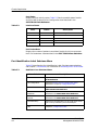
Summary of Changes
Version
Date
Reason/Rational
Nature of Changes
MRXI-22/24
Management Module Guide
Notice
Cabletron Systems reserves the right to make changes in specifications and other information
contained in this document without prior notice. The reader should in all cases consult Cabletron
Systems to determine whether any such changes have been made.
The hardware, firmware, or software described in this manual is subject to change without notice.
IN NO EVENT SHALL CABLETRON SYSTEMS BE LIABLE FOR ANY INCIDENTAL,
INDIRECT, SPECIAL, OR CONSEQUENTIAL DAMAGES WHATSOEVER (INCLUDING BUT
NOT LIMITED TO LOST PROFITS) ARISING OUT OF OR RELATED TO THIS MANUAL OR
THE INFORMATION CONTAINED IN IT, EVEN IF CABLETRON SYSTEMS HAS BEEN
ADVISED OF, KNOWN, OR SHOULD HAVE KNOWN, THE POSSIBILITY OF SUCH
DAMAGES.
Copyright © April, 1998, by Cabletron Systems, Inc. All rights reserved.
Printed in the United States of America.
Order Number: 9030751 E7
Cabletron Systems, Inc.
P.O. Box 5005
Rochester, NH 03866-5005
SPECTRUM, the SPECTRUM IMT/VNM logo, DCM, IMT, and VNM are registered
trademarks, and SpectroGRAPH, SpectroSERVER, Inductive Modeling Technology,
Device Communications Manager, and Virtual Network Machine are trademarks of
Cabletron Systems, Inc.
Ethernet is a trademark of Xerox Corporation.
9030751 E7
v
Virus Disclaimer
Cabletron Systems makes no representations or warranties to the effect that the Licensed
Software is virus-free.
Cabletron has tested its software with current virus checking technologies. However, because no
anti-virus system is 100% reliable, we strongly caution you to write protect and then verify that
the Licensed Software, prior to installing it, is virus-free with an anti-virus system in which you
have confidence.
Restricted Rights Notice
(Applicable to licenses to the United States Government only.)
1. Use, duplication, or disclosure by the Government is subject to restrictions as set forth in
subparagraph (c) (1) (ii) of the Rights in Technical Data and Computer Software clause at
DFARS 252.227-7013.
Cabletron Systems, Inc., 35 Industrial Way, Rochester, New Hampshire 03866-5005.
2. (a) This computer software is submitted with restricted rights. It may not be used,
reproduced, or disclosed by the Government except as provided in paragraph (b) of this
Notice or as otherwise expressly stated in the contract.
(b) This computer software may be:
(c)
(1)
Used or copied for use in or with the computer or computers for which it was
acquired, including use at any Government installation to which such computer or
computers may be transferred;
(2)
Used or copied for use in a backup computer if any computer for which it was
acquired is inoperative;
(3)
Reproduced for safekeeping (archives) or backup purposes;
(4)
Modified, adapted, or combined with other computer software, provided that the
modified, combined, or adapted portions of the derivative software incorporating
restricted computer software are made subject to the same restricted rights;
(5)
Disclosed to and reproduced for use by support service contractors in accordance with
subparagraphs (b) (1) through (4) of this clause, provided the Government makes
such disclosure or reproduction subject to these restricted rights; and
(6)
Used or copied for use in or transferred to a replacement computer.
Notwithstanding the foregoing, if this computer software is published copyrighted
computer software, it is licensed to the Government, without disclosure prohibitions, with
the minimum rights set forth in paragraph (b) of this clause.
(d) Any other rights or limitations regarding the use, duplication, or disclosure of this
computer software are to be expressly stated in, or incorporated in, the contract.
(e)
vi
This Notice shall be marked on any reproduction of this computer software, in whole or in part.
MRXI-22/24
Management Module Guide
Contents
Preface
What Is in This Guide .......................................................................................................... ix
Conventions ............................................................................................................................x
Related SPECTRUM Documentation....................................................................................x
Other Related Documentation ............................................................................................. xi
Chapter 1
Introduction
What Is in this Chapter ..................................................................................................... 1-1
MRXI-22/24 Management Module..................................................................................... 1-1
SPECTRUM Model Type.................................................................................................... 1-2
Accessing SPECTRUM Views ............................................................................................ 1-2
SPECTRUM Views Roadmap ............................................................................................ 1-5
SPMA Support .................................................................................................................... 1-6
Chapter 2
Device Views
What Is in this Chapter ..................................................................................................... 2-1
Chassis Device View ........................................................................................................... 2-2
Device Icon.................................................................................................................... 2-3
Device Identification Label ................................................................................... 2-4
Device Icon Subviews Menu.................................................................................. 2-4
Port Identification Label .............................................................................................. 2-5
Port Identification Label Subviews Menu ............................................................ 2-6
Chapter 3
Configuration Views
What Is in this Chapter ..................................................................................................... 3-1
MRXI Device Configuration View ...................................................................................... 3-2
Device Configuration Information............................................................................... 3-2
MRXI-22/24 Component Table View..................................................................... 3-3
Interface Configuration Table...................................................................................... 3-3
Community String Information View ......................................................................... 3-4
Repeater Configuration View ............................................................................................. 3-4
Repeater Management................................................................................................. 3-5
Source Address Management ...................................................................................... 3-5
Trap Configuration....................................................................................................... 3-6
Alarm Configuration .................................................................................................... 3-6
Error Source ................................................................................................................. 3-7
Board Map .................................................................................................................... 3-8
Manages........................................................................................................................ 3-8
9030751 E7
iii
Chapter 3
Configuration Views (Continued)
Module and Port Configuration Views ...............................................................................3-8
Module Management (Module Configuration View Only)..........................................3-8
Port Management (Port Configuration View Only) ....................................................3-9
Trap Configuration .....................................................................................................3-10
Alarm Configuration...................................................................................................3-10
Error Source................................................................................................................3-11
Source Addressing.............................................................................................................3-12
Module Source Address Table View ...........................................................................3-12
Source Address Board/Port Location View ................................................................3-12
Port Source Address Table View ................................................................................3-13
Chapter 4
Event and Alarm Messages
What Is in this Chapter ......................................................................................................4-1
MRXI-22/24 Events and Alarms.........................................................................................4-1
Index
iv
MRXI-22/24
Management Module Guide
Figures
Chapter 1
Figure 1-1.
Figure 1-2.
Figure 1-3.
Figure 1-4.
Figure 1-5.
Chapter 2
Figure 2-1.
Figure 2-2.
Figure 2-3.
Introduction
Using Double-Click Zones to Access SPECTRUM View ..................................... 1-3
Using the Icon Subviews Menu to Access SPECTRUM Views .......................... 1-4
Accessing Device-Specific Subviews from Labels ............................................... 1-4
SPECTRUM Views Roadmap .............................................................................. 1-5
SPMA Applications View ...................................................................................... 1-6
Device Views
Chassis Device View ............................................................................................. 2-2
Device Icon ............................................................................................................ 2-3
Port Identification Label ...................................................................................... 2-5
9030751 E7
v
vi
MRXI-22/24
Management Module Guide
Tables
Chapter 2
Table 2-1.
Table 2-2.
Table 2-3.
Chapter 4
Table 4-1.
Device Views
Device Icon Subviews Menu.................................................................................. 2-4
Interface Status ..................................................................................................... 2-6
Hub Stack Icon Subviews Menu ........................................................................... 2-6
Event and Alarm Messages
MRXI-22/24 Events and Alarms ........................................................................... 4-1
9030751 E7
vii
viii
MRXI-22/24
Management Module Guide
Preface
Use this guide as a reference for the SPECTRUM MRXI-22/24 management
software. Before using this guide, you should be familiar with SPECTRUM’s
functions and navigational techniques as described in the Administration
documentation and the Operation documentation.
For the purposes of this guide, the MRXI-22/24 is referred to as “device.”
What Is in This Guide
The following outlines the organization of the MRXI-22/24 Management
Module Guide:
Chapter
Description
Chapter 1
Describes the device, the management module,
and model types. This chapter also provides
information on accessing device-specific views.
Introduction
Chapter 2
Device Views
Chapter 3
Configuration Views
Chapter 4
Event and Alarm Messages
NOTE
Describes the Device views representing the
device.
Describes the Configuration views for the device
and the network management information
provided by these views.
Lists and explains the event and alarm messages
generated in the Event Log or Alarm Manager for
the device.
There is no Application View chapter in this book. All applications available
for this device are described in the Bridging Applications Reference, the
MIB II Applications Reference, or the Miscellaneous Applications
Reference.
9030751 E7
ix
Conventions
Conventions
This guide uses the following conventions:
• Menu selections and buttons referenced in text appear in bold; for
example, Configuration or Detail.
• Button names appear in shadowed boxes when introducing paragraphs
describing their use; for example:
Help
• Menu navigation appears in order of selection; for example, Icon
Subviews -> Utilities -> Application.
• Referenced chapter titles and section headings appear in italics.
• Referenced documents appear in bold italics.
• MRXI-22/24 is referred to as “device.”
• References in blue are hypertext links for online documents.
Related SPECTRUM Documentation
When using this guide, you should have a clear understanding of SPECTRUM
functionality and navigational techniques as described in the Administration
documentation, the Operation documentation and the following
documentation:
SPECTRUM Report Generator User’s Guide
Getting Started with SPECTRUM for Operators
Getting Started with SPECTRUM for Administrators
How to Manage Your Network with SPECTRUM
Preface
x
MRXI-22/24
Management Module Guide
Other Related Documentation
Other Related Documentation
Refer to the following documentation for more information on managing TCP/
IP-based networks:
Martin, James, Kathleen Kavanagh Chapman, Joe Leben. Local Area
Networks: Architectures and Implementations, 2d ed. Englewood Cliffs,
NJ: Prentice Hall, 1994.
Rose, Marshall T. The Simple Book: An Introduction to Management of
TCP/IP-based Internets. Englewood Cliffs, NJ: Prentice Hall, 1991.
Stallings, William. Data and Computer Communications, 4th ed. New
York: Macmillan Publishing Company, 1994.
Tanenbaum, Andrew S. Computer Networks, 3d ed. Englewood Cliffs, NJ:
Prentice Hall, 1996.
9030751 E7
Preface
xi
Other Related Documentation
Preface
xii
MRXI-22/24
Management Module Guide
Chapter 1
Introduction
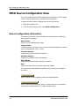
What Is in this Chapter
This chapter introduces the SPECTRUM management module for the MRXI22/24. It describes the following:
•
•
•
•
•
MRXI-22/24 Management Module
SPECTRUM Model Type
Accessing SPECTRUM Views
SPECTRUM Views Roadmap
SPMA Support
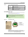
MRXI-22/24 Management Module
The MRXI-22 and MRXI-24 are standalone multi-port repeating hubs. The
MRXI-22 contains twelve RJ-45 connectors, the MRXI-24 contains 24 RJ-45
connectors. Both devices support additional network connections through the
use of one interchangeable front panel Ethernet Port Interface Module
(EPIM). A variety of EPIMs permit the expansion of an 802.3 network by
supporting UTP, STP, fiber optic, Thin Ethernet, and AUI network
connections.
9030751 E7
1-1
SPECTRUM Model Type
SPECTRUM Model Type
The model type HubCSIMRXi refers to the management module software
package used to specify attributes, actions, and associations for the physical
MRXI-22 or -24 device using the Simple Network Management Protocol
(SNMP) and Management Information Bases (MIBs) for that device.
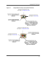
Accessing SPECTRUM Views
Icons and labels that display information within an icon, provide access to
SPECTRUM views. This is done using double-click zones (Figure 1-1) or Icon
Subviews menus (Figure 1-2)
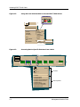
To access the Icon Subviews menu as shown in Figure 1-2 and Figure 1-3, do
the following:
1. Highlight the icon or label.
2. From the View menu, select Icon Subviews or click the applicable mouse
button (middle or right). Refer to the SPECTRUM Icons Reference for
information on configuring your mouse.
Introduction
1-2
MRXI-22/24
Management Module Guide
Accessing SPECTRUM Views
Figure 1-1.
Using Double-Click Zones to Access SPECTRUM View
Accesses the Configuration view;
see Chapter 3, Configuration Views.
Accesses the Device Topology view;
refer to the SPECTRUM Views
Reference.
Model Name
Accesses the Device view;
see Chapter 2, Device Views.
HubCSIMRXi
Accesses the Performance view;
refer to the SPECTRUM Views
Reference.
Accesses the Application view;
refer to the Bridging Applications
Reference, the MIB II Applications
Reference, or the Miscellaneous
Applications Reference.
Accesses the Configuration view;
see Chapter 3, Configuration Views.
Accesses the Device view;
see Chapter 2, Device Views.
Model Name
Accesses the Performance view;
refer to the SPECTRUM Views
Reference.
HubCSIMRXi
Accesses the Device Topology view;
refer to the SPECTRUM Views
Reference.
9030751 E7
Accesses the Application view;
refer to the Bridging Applications
Reference, the MIB II Applications
Reference, or the Miscellaneous
Applications Reference.
Introduction
1-3
Accessing SPECTRUM Views
Figure 1-2.
Using the Icon Subviews Menu to Access SPECTRUM Views
Model Name
HubCSIMRXi
View
Go Back
Ctrl+b
Go Up
Icon Subviews
View Path
New View
Bookmarks
View History...
Current View Info...
Notes...
Jump by name...
Zoom
Map Hierarchy
Figure 1-3.
Close
Ctrl+c
Navigate
Alarms
Performance
Notes...
Utilities
Zoom
Device
Chassis
DevTop
Physical
Accessing Device-Specific Subviews from Labels
1
MRXi22
12 ON
11 ON
10 ON
3
ON
2
ON
Close
Alt+F4
Navigate
Alarms
Performance
Notes...
Utilities
Port Notes
Port Configuration
Port Performance
Port Frame & Error Breakdown
Port Frame Size & Protocols
Port Redundancy
Port Source Address Table
Port Security Configuration
Enable/Disable Port
Introduction
1-4
1
ON
E1
13 ON
Common
Device-Specific
MRXI-22/24
Management Module Guide
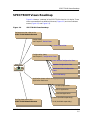
SPECTRUM Views Roadmap
SPECTRUM Views Roadmap
Figure 1-4 shows a “roadmap” of the SPECTRUM views for this device. These
views are accessible from double-click zones (Figure 1-1) and Icon Subviews
menus (Figure 1-2, and Figure 1-3).
Figure 1-4.
SPECTRUM Views Roadmap
Performance view; refer to the
SPECTRUM Views Reference.
Device views;
see Chapter 2, Device Views.
Chassis Device View.
Configuration views;
see Chapter 3, Configuration Views.
MRXI Device Configuration View.
Repeater Configuration View.
Model Name
Module and Port Configuration
Views.
MRXi-22
Source Addressing.
Application views; refer to the appropriate
Application Reference.
Bridging Application.
MIB II Application.
Download Application.
RMON (Available separately).
DevTop view; refer to the
SPECTRUM Views Reference.
9030751 E7
DLM (Available separately).
Introduction
1-5
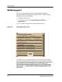
SPMA Support
SPMA Support
SPECTRUM also supports the SPECTRUM Portable Management
Application (SPMA) functionality for the MRXI-22/24. To open the SPMA
Applications view, do the following:
1. Highlight the Device icon.
2. From the View menu, select Icon Subviews -> Utilities ->
Applications....
Figure 1-5 shows an example of an SPMA Applications view.
Figure 1-5.
SPMA Applications View
Applications
Example of type HubCSIMRXi
Community Names Hub View
Trap Table
Repeating of type MRXiRptr
Alarm Configuration
Redundancy
Port Source Address
Link/Seg Traps
Source Addressing
Security Configuration
MIB-II of type SNMP2_Agent
Generic SNMP (MIB I II)
Download App of type CtDownLoadApp
TFTP Download
Standard RMON of type RMONApp
RMON Load Monitor
RMON Protocol Analyzer
E Probe 01 of type RMONEthProbe
RMON Load Monitor
RMON Protocol Analyzer
Close
The buttons within the SPMA Applications view provide access to SPMAspecific views and dialog boxes. The Applications view for a particular device
may include different buttons depending upon the applications available, the
BRIM’s installed, and the configuration of your device. Refer to the
SPECTRUM Portable Management Application for the MRXI-22/24
User’s Guide or the SPECTRUM Portable Management Application
Tools Guide.
Introduction
1-6
MRXI-22/24
Management Module Guide
Chapter 2
Device Views
What Is in this Chapter
This chapter describes the following Device views and subviews available for
the MRXI-22/24:
• Chassis Device view
See Chapter 1, Introduction for information on Accessing SPECTRUM Views.
9030751 E7
2-1
Chassis Device View
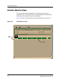
Chassis Device View
This view shows a logical representation of the device chassis and its
interfaces or ports. The Chassis Device view provides menu and double-click
zone access to the views that monitor the interfaces.
Figure 2-1 shows an example of the Chassis Device view for the MRXI-22.
Figure 2-1.
Chassis Device View
Example of type HubCSIMRXi of Landscape daedalus:Primary
*
File
View
Help?
Model Name
Network Address
Sys Up Time
Contact
Manufacturer
Description
Device Type
Primary Application
Location
Device
Icon
Serial Number
1
MRXi22
12 ON 11 ON 10 ON
9
ON
8
ON
7
ON
6
ON
5
ON
4
ON
3
ON
2
ON
1
ON
E1
13 ON
Port Label
Device Views
2-2
MRXI-22/24
Management Module Guide
Chassis Device View
Device Icon
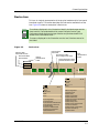
Device Icon
This icon is a logical representation of the physical module and its front panel
interfaces or ports. This section describes the information available from the
icon. Figure 2-2 shows an example of a Device icon.
The callouts displayed in this illustration identify the label name and the
view to which it provides double-click access. Example: Device Type/
Performance View displays the type of device and provides double-click
access to the Performance View.
NOTES
The menus displayed in the illustration are the Icon Subviews menus for
that label.
Figure 2-2.
Device Icon
Port Number/
Port Zones
Device Label/
Performance View
Device Number/
Device Notes
Port Status Label/
Port Configuration View
Device
Identification
Label
Port
Identification
Label
Port Packet Rate Label/
Port Performance View
1
MRXi22
12
ON
11
ON
10
ON
3
ON
2
Close
Alt+F4
Navigate
Alarms
Performance
Notes...
Utilities
Zoom
Port Notes
Port Configuration
Port Performance
Port Frame & Error Breakdown
Port Frame Size & Protocols
Port Redundancy
Port Source Address Table
Port Security Configuration
Enable/Disable Port
9030751 E7
ON
1
ON
E1
13
ON
Close
Alt+F4
Navigate
Alarms
Performance
Notes...
Utilities
MRXI Model Information
MRXI Configuration
Application View
Module Notes
Module Configuration
Module Performance
Module Frame & Error Breakdown
Module Frame Size
Module DevTop View
Module Source Address Table
Find Source Address
Module Security Configuration
Repeater Redundancy
Enable All Ports
Device Views
2-3
Chassis Device View
Device Icon
Device Identification Label
This label provides the following information (See Figure 2-2):
Device Number
Identifies the device’s location in the Stack. Double-click this area to open the
Notes Facility described in the SPECTRUM Views Reference.
Device Label
Identifies the type of device. Double-click this label to open the Performance
view described in the SPECTRUM Views Reference.
Device Icon Subviews Menu
Table 2-1 lists each of the device-specific Icon Subviews menu selections
available for this device. For information on Accessing SPECTRUM Views, see
Chapter 1, Introduction.
Table 2-1.
Device Icon Subviews Menu
Menu Selection
Device Views
2-4
Description
MRXI Model
Information
Opens the MRXI Model Information view described in the
SEPCTRUM Views Reference.
MRXI Configuration
Opens the MRXI Device Configuration View described in
Chapter 3, Configuration Views.
Application View
Opens the MRXI Application view described in the
SEPCTRUM Views Reference.
Module Notes
Opens the Notes view described in the SEPCTRUM Views
Reference.
Module
Configuration
Opens the Module and Port Configuration Views described in
Chapter 3, Configuration Views.
Module
Performance
Opens the Module Performance view described in the
SEPCTRUM Views Reference.
Module Frame &
Error Breakdown
Opens the Module Frame & Error Breakdown view
described in the SEPCTRUM Views Reference.
Module Frame Size
Opens the Module Frame Size view described in the
SEPCTRUM Views Reference.
Module DevTop
View
Opens the Device Topology view described in the
SEPCTRUM Views Reference.
Module Source
Address Table
Opens the Module Source Address Table View described in
Chapter 3, Configuration Views.
Find Source Address
Allows you to find a Source Address on the Module Source
Address Table.
MRXI-22/24
Management Module Guide
Chassis Device View
Port Identification Label
Table 2-1.
Device Icon Subviews Menu (Continued)
Module Security
Configuration
Opens the Repeater Security View described in the
SPECTRUM Portable Management Application for the
MRXI-22/24 User’s Guide.
Repeater
Redundancy
Opens the Repeater Redundancy Circuit View which allows
you to set up redundancy on the device.
Enable All Ports
Displays the Enable All Ports view, which allows you to
enable all the ports on the module.
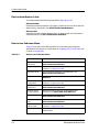
Port Identification Label
This label provides access to the Icon Subviews menu for the individual ports.
It contains the following information (see Figure 2-3).
NOTES
The callouts displayed in this illustration identify the label name and the
view to which it provides double-click access. Example: Device Type/
Performance View displays the type of device and provides double-click
access to the Performance View.
The menus displayed in the illustration are the Icon Subviews menus for
that label.
Figure 2-3.
Port Identification Label
Close
Alt+F4
Navigate
Alarms
Performance
Notes...
Utilities
Zoom
Port Notes
Port Configuration
Port Performance
Port Frame & Error Breakdown
Port Frame Size & Protocols
Port Redundancy
Port Source Address Table
Port Security Configuration
Enable/Disable Port
Port
Identification
Label
Port Number/
Port Notes View
3
ON
Port Status/
Port Configuration View
Port Packet Rate/
Port Performance View
Port Number
Displays the number of the port represented. For the MRXi-22, labels 1
through 12 refer to the port, and 13 to the EPIM. For the MRXi-24, 1 through
22 refer to the port, and 23 to the EPIM. Double-click this area to open the
Notes view described in the SPECTRUM Views Reference.
9030751 E7
Device Views
2-5
Chassis Device View
Port Identification Label
Port Status
Displays the port activity status. Table 2-2 lists the possible states. Doubleclick this label to open the Port Configuration view described in the
SPECTRUM Views Reference.
Table 2-2.
Interface Status
Color
Status
Description
Green
ON
Port is forwarding.
Blue
UNK
The status is unknown.
Blue
OFF
Port is off.
Red
SEG
Segmented.
Yellow
NLK
No Link.
Port Packet Rate
Displays the number of packets transmitted. Double-click this area to open
the Error Breakdown view described in the SPECTRUM Views Reference.
Port Identification Label Subviews Menu
Table 2-3 describes the Port Identification Label Subviews menu selections.
See Chapter 1, Introduction, for information on Accessing SPECTRUM Views.
Table 2-3.
Hub Stack Icon Subviews Menu
Menu Selection
Device Views
2-6
Description
Port Notes
Opens the Notes view described in the SPECTRUM
Views Reference.
Port Configuration
Opens the Module and Port Configuration Views
described in Chapter 3, Configuration Views.
Port Performance
Opens the Port Performance view described in the
SPECTRUM Views Reference.
Port Frame & Error
Breakdown
Opens the Port Frame & Error Breakdown view
described in the SPECTRUM Views Reference.
Port Frame Size &
Protocols
Opens the Port Frame Size & Protocols view described
described in the SPECTRUM Views Reference.
Port Redundancy
Opens the Port Redundancy Circuit View which allows
you to set up redundancy on the selected port.
Port Source Address
Table
Opens the Port Source Address Table View described in
Chapter 3, Configuration Views.
MRXI-22/24
Management Module Guide
Chassis Device View
Port Identification Label
Table 2-3.
9030751 E7
Hub Stack Icon Subviews Menu (Continued)
Port Security
Configuration
Opens the Repeater Security View described in the
SPECTRUM Portable Management Application
for the MRXi-22/-24 User’s Guide.
Enable/Disable Port
Displays the Enable/Disable Port View which allows
you to toggle the selected port between enabled and
disabled states.
Device Views
2-7
Chassis Device View
Port Identification Label
Device Views
2-8
MRXI-22/24
Management Module Guide
Chapter 3
Configuration Views
What Is in this Chapter
This chapter describes the Configuration views available for the MRXI-22/24
hubs. These views display network configuration and operating information
for the device and its interfaces.
The following Configuration views are available for this device:
•
•
•
•
•
MRXI Device Configuration View
Repeater Configuration View
Module Configuration View
Port Configuration View
Source Address View
Refer to Chapter 1, Introduction, for information on Accessing SPECTRUM
Views.
9030751 E7
3-1
MRXI Device Configuration View
MRXI Device Configuration View
This view provides device-specific configuration information as well as access
to other views that allow you to configure device components.
To access the MRXI Device Configuration view do the following:
1. Highlight the device icon.
2. From the Icon Subviews menu, select MRXI Configuration.
Device Configuration Information
This section of the MRXI Device Configuration view displays the following
device-specific information:
Device Name
Displays the user-defined device name.
Contact Status
Indicates whether a connetcion with the device has been established. Possible
values are Established, Lost, or Initial.
Firmware Revision
Displays the firmware version of the device.
Hardware Revision
Displays the hardware version of the device.
MAC Address
Displays the Ethernet (MAC) address of the device.
Date
Displays the date that the current firmware was loaded.
This view also provides the following buttons, which allow you to configure
this device:
Component Table
Opens the MRXI-22/24 Component Table View described below.
DownLoad Application
Opens the DownLoad Application view. This view allows you to upgrade the
firmware for the device from a TFTP Boot or Bootp Server.
Configuration Views
3-2
MRXI-22/24
Management Module Guide
MRXI Device Configuration View
Interface Configuration Table
MRXI-22/24 Component Table View
This view provides information on the device firmware components. Clicking
in the Community String Fields allows you to change the selected component’s
community strings. The Component Status button allows you to enable or
disable the selected component.
ID
Displays the identification number for this component.
Name
Displays the name of this component.
Basic Community String
Displays the community password. The default value for this entry is Public.
Status
Displays the administrative security status of the component. Possible states
are Unknown, Invalid, Enabled, Testing, Operational, Error, Disabled, and
Delete.
Interface Configuration Table
This section of the MRXI Device Configuration View provides the following
interface configuration information:
Number of Interfaces
Displays the current number of interfaces in this Interface Configuration
Table.
Description
Displays a description of the interface including the manufacturer, product
name, and version number of the hardware interface.
Type
Displays the type of interface. Possible interface types and a brief description
of each type are shown under MRXI-22/24 Component Table View.
Bandwidth
Displays the estimated bandwidth of the interface measured in bits per
second. For interfaces that do not vary in bandwidth or for which no accurate
estimate can be made, a nominal bandwidth is provided.
Phy Address
Displays the Ethernet (MAC) address of the interface.
Oper Status
Displays the current operational state of the interface (Up, Down, or Testing).
Admin Status
Displays the desired operational state of the interface (Up, Down, or Testing).
9030751 E7
Configuration Views
3-3
Repeater Configuration View
Community String Information View
Change Time
Displays the SystemUpTime value when the interface entered its current
operational state.
Q. Length
Displays the maximum length of the outbound queue in packets.
P. Size
Displays the largest Maximum Transmission Unit (MTU) that can be
transmitted or received by the interface measured in octets.
Community String Information View
This view provides detailed information on a specific entry in the Component
Table, and allows you to modify user-settable fields. You can access this view
by double-clicking on the desired entry in the Component Table.
ID
Displays the component identification number.
Name
Displays the name of this component.
Version
Displays the version number for this firmware component.
Administrative Status
Allows you to set the administrative security status of the component.
Possible states are Unknown, Invalid, Enabled, Testing, Operational, Error,
Disabled, and Delete.
Basic Community String
Displays the basic community string for this component. The default is Public.
Read Only Community String
Displays the read only community string for this component.
Read Write Community String
Displays the read write community string for this component.
Super User Community String
Displays the super user community string for this component.
Repeater Configuration View
This view provides information on the MRXI-22/24 network, host, port, and
model configuration.
Configuration Views
3-4
MRXI-22/24
Management Module Guide
Repeater Configuration View
Repeater Management
To access the Repeater Configuration view do the following:
1. Within the Application view, highlight the MRXiRptr icon.
2. From the Icon Subviews menu, select Configuration.
Repeater Management
This area of the Repeater Configuration view provides the following port
information:
Port Count
Displays the total number of ports on this LAN segment.
Ports On
Displays the total number of ports on this network currently in the ON state.
Ports Operational
Displays the number of ports on this network currently transmitting/receiving
data.
Network Ports
Allows you to Enable all the ports on this network segment.
Network Port Security
Allows you to configure the security state for the ports on this network
segment.
Source Address Management
This area of the Repeater Configuration view provides the following source
address information:
Ageing Interval
Displays the timeout period, in seconds. The timeout period is how long
dynamically learned forwarding information remains in the database before
being selected. You can modify this value.
9030751 E7
Configuration Views
3-5
Repeater Configuration View
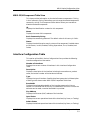
Trap Configuration
Trap Configuration
This area of the Repeater Configuration view allows you to enable or disable
any of the following types of traps:
Link Traps
Allows you to Enable the Link Trap generation, such that all packets
indicating a change in link status are reported within the trap database.
Segmentation Traps
Allows you to Enable the Segmentation Trap generation, such that all packets
indicating a change in segmentation status are reported within the trap
database.
Source Address Traps
Allows you to Enable the Source Address Trap generation, such that all
packets indicating a change in source address are reported within the trap
database.
Alarm Configuration
This area of the Repeater Configuration view provides the following
configuration and status information for generating alarms for the device:
Timebase
Allows you to set the number of seconds used as the interval for performing all
of the rate alarm checks. The minimum is 10 seconds. For example, if the
timebase is 10 seconds, an alarm will occur only when the specified number of
errors occur within 10 seconds.
Traffic Alarms
Allows you to configure whether traffic alarms are disabled or enabled.
Traffic Threshold
Displays the threshold number of packets, within the alarm timebase, that
will generate a traffic alarm. You can modify this value.
Collision Alarms
Allows you to configure whether collision alarms are disabled or enabled.
Configuration Views
3-6
MRXI-22/24
Management Module Guide
Repeater Configuration View
Collision Threshold
Displays the threshold number of collisions per good packet, within the alarm
timebase, that will generate a collision alarm. You can modify this value.
Broadcast Alarms
Allows you to configure whether broadcast alarms are disabled or enabled.
Broadcast Threshold
Displays the threshold number of broadcasts received, within the alarm
timebase, that will generate a broadcast alarm. You can modify this value.
Error Alarms
Allows you to configure whether error alarms are disabled or enabled.
Error Threshold
Displays the percentage of errors per good packet, within the alarm timebase,
that will generate an error alarm.
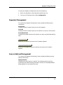
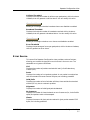
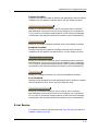
Error Source
This area of the Repeater Configuration view provides a series of buttons,
allowing you to select the types of errors to include in the error sum. The
selectable error types are as follows:
CRC
Displays the number of packets received with bad Cyclical Redundancy
Checks (CRC).
Runts
Displays the number of runt packets received. A runt packet is one byte less
than the standard Ethernet frame of 64 bytes, not including preamble.
OOW_Colls
Displays the number of out-of-window collisions, those outside the standard
window (51.2µs), due to a network problem.
Alignment
Displays the number of misaligned packets detected.
No_Resource
Displays the number of times the board ran out of resources (i.e., lack of buffer
space) and packets could not be accepted.
Giants
Displays the amount of giant packets received. A giant packet exceeds 1518
bytes, not including preamble.
9030751 E7
Configuration Views
3-7
Module and Port Configuration Views
Board Map
Board Map
This area of the Repeater Configuration view displays a series of read-only
indicators displaying the slot numbers where the repeater resides in the
MMAC-FNB chassis. Standalone devices, such as the MRXI-22/24, will always
exist in Slot-1.
Manages
This area of the Repeater Configuration view displays the user-supplied or
default model name of the device managing this repeater. This section also
allows you to access the Device Configuration view by double-clicking the
name, or highlighting the name and clicking OK.
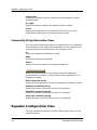
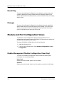
Module and Port Configuration Views
The Module or Port Configuration views provide information on the
configuration and operating status of the MRXI-22/24 module as a whole or of
selected individual ports on the module.
To access the Module Configuration view do the following:
1. Highlight the device icon.
2. From the Icon Subviews menu, select Module Configuration or Port
Configuration.
Module Management (Module Configuration View Only)
This area of the Module Configuration view provides the following port
information for the selected module:
Port Count
Displays the total number of ports on this module.
Ports On
Displays the total number of ports on this module currently in the ON state.
Configuration Views
3-8
MRXI-22/24
Management Module Guide
Module and Port Configuration Views
Ports Operational
Displays the number of ports on this module currently transmitting/receiving
data.
Module Ports
Allows you to Enable all the ports on this module. You can also enable module
ports by selecting Enable All Ports from the Icon Subviews menu.
Port Management (Port Configuration View Only)
This area of the Port Configuration view provides the following information
for the selected port:
Port ID
Displays the number of the module port.
Administrative Status
Allows you to configure the desired state of the port (Enable or Disable).
Operational Status
Displays the current operational state of the port (Not-Operational or
Operational).
Segmentation Status
Displays the current segmentation state of the port (Not-Segmented or
Segmented).
Link Status
Displays the current link state of the port (Not-Linked, Linked, or NotApplicable).
Topological State
Displays the current port topological state (Station or Trunk).
Set Topological State
Allows you to configure the desired port topological state (Not_Forced or
Forced_Trunk).
9030751 E7
Configuration Views
3-9
Module and Port Configuration Views
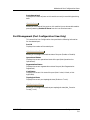
Trap Configuration
Trap Configuration
This area of the Module or Port Configuration View allows you to enable or
disable any of the following types of traps:
Link Traps
Allows you to Enable Link Trap generation, such that all packets indicating a
change in link status are reported within the trap database.
Segmentation Traps
Allows you to Enable Segmentation Trap generation, such that all packets
indicating a change in segmentation status are reported within the trap
database.
Source Address Traps
Allows you to Enable Source Address Trap generation, such that all packets
indicating a change in source address are reported within the trap database.
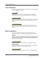
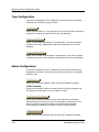
Alarm Configuration
This area of the Module or Port Configuration view provides the following
configuration and status information for generating alarms for the selected
module or port:
Traffic Alarms
Allows you to configure whether traffic alarms are disabled or enabled.
Traffic Threshold
Displays the threshold number of packets, within the alarm timebase, that
will generate a traffic alarm. You can modify this value.
Traffic Alarm Condition
Allows you to disable the module or port if the traffic alarm conditions
described above are met and an alarm for the module is generated. This is
useful in preventing excessive network traffic from alarm messages
transmitted by the module, and allows for module troubleshooting.
Collision Alarms
Allows you to configure whether collision alarms are disabled or enabled.
Configuration Views
3-10
MRXI-22/24
Management Module Guide
Module and Port Configuration Views
Collision Threshold
Displays the threshold number of collisions per good packet, within the alarm
timebase, that will generate a collision alarm. You can modify this value.
Collision Alarm Condition
Allows you to disable the module or port if the collision alarm conditions
described above are met and an alarm for the module or port is generated.
This is useful in preventing excessive network traffic from alarm messages
transmitted by the module, and allows for module or port troubleshooting.
Broadcast Alarms
Allows you to configure whether broadcast alarms are disabled or enabled.
Broadcast Threshold
Displays the threshold number of broadcasts received, within the alarm
timebase, that will generate a broadcast alarm. You can modify this value.
Broadcast Alarm Condition
Allows you to disable the module or port if the broadcast alarm conditions
described above are met, and an alarm for the module or port is generated.
This is useful in preventing excessive network traffic from alarm messages
transmitted by the module, and allows for module or port troubleshooting.
Error Alarms
Allows you to configure whether error alarms are disabled or enabled.
Error Threshold
Displays the percentage of errors per good packet, within the alarm timebase,
that will generate an error alarm. You can modify this value.
Error Alarm Condition
Allows you to disable the module or port if the error alarm conditions
described above are met and an alarm for the module or port is generated.
This is useful in preventing excessive network traffic from alarm messages
transmitted by the module, and allows for module or port troubleshooting.
Error Source
This view is the same as that described under Error Source in the section on
Repeater Configuration View.
9030751 E7
Configuration Views
3-11
Source Addressing
Source Addressing
Source Address Tables are used to determine which frames will be forwarded
from one network segment to another. This section provides a description of
the source addressing views used to establish a source address table for the
MRXI-22/24.
Module Source Address Table View
To access the Module Source Address Table view do the following:
1. Highlight the MRXI-22/24 Device Icon.
2. From the Icon Subviews menu, select Module Source Address Table.
This view provides the following information:
Source Address
The addresses of the source devices sending packets received by the MRXI-22/
24 module over any port.
Port ID
The number identifying the port over which the module received the packet
from the corresponding source address.
Board ID
The number identifying the MRXI-22/24 module. This value will always be 1.
Source Address Board/Port Location View
To access the Source Address Board/Port Location view do the following:
1. Highlight the MRXI-22/24 Device Icon.
2. From the Icon Subviews menu, select Find Source Address.
This view provides the following information:
Model Name
The network name of the MRXI-22/24 being modeled.
Network Address
The IP address of the MRXI-22/24 being modeled.
Source Address
Enter the desired ethernet address here, using the File/Update feature.
Configuration Views
3-12
MRXI-22/24
Management Module Guide
Source Addressing
Port Source Address Table View
Board Number
The module through which packets are being sent for the specified ethernet
source address.
Port Number
The port through which packets are being sent for the specified ethernet
source address.
Port Source Address Table View
To access the Port Source Address Table view do the following:
1. Highlight the MRXI-22/24 Device Icon.
2. From the Icon Subviews menu, select Port Source Address Table.
This view provides the following information:
Name
Name of the application (Repeating) being run by the port.
Network Address
The IP address of the MRXI-22/24 being modeled.
Device Type
A textual identifier for the kind of device being modeled.
Slot/Port Number
The number identifying the module and port this table applies to, in the
format module.port. The value of the module will always be 1.
Port Source Address Table
The addresses of the source devices sending packets received by the MRXI-22/
24 module over this port.
9030751 E7
Configuration Views
3-13
Source Addressing
Port Source Address Table View
Configuration Views
3-14
MRXI-22/24
Management Module Guide
Chapter 4
Event and Alarm Messages
What Is in this Chapter
This chapter describes the types of events and alarms generated by the MRXI22/24 and any probable cause messages corresponding to these alarms.
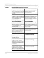
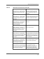
MRXI-22/24 Events and Alarms
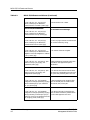
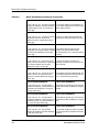
Table 4-1 describes the event messages appearing in the Event Log, and any
corresponding probable cause messages that may be displayed in the
Enterprise Alarm Manager View for the MRXI-22/24.
Table 4-1.
MRXI-22/24 Events and Alarms
Message in the Event Log
Alarm View Probable Cause
Message
CsEvFormat/Event00010306
No Probable cause message.
{d "%w- %d %m-, %Y - %T"} A(n) {t}
device, named {m}, has been cold started.
(event [{e}])
CsEvFormat/Event00010307
No Probable cause message.
{d "%w- %d %m-, %Y - %T"} A(n) {t}
device, named {m} has been warm started.
(event [{e}])
9030751 E7
4-1
MRXI-22/24 Events and Alarms
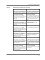
Table 4-1.
MRXI-22/24 Events and Alarms (Continued)
CsEvFormat/Event00010308
CsPCause/Prob00010308
{d "%w- %d %m-, %Y - %T"} A(n) {t}
device, named {m}, has detected a
communication Link Down. (event [{e}])
Communication link is down.
CsEvFormat/Event00010309
No Probable cause message.
{d "%w- %d %m-, %Y - %T"} A(n) {t}
device, named {m}, has detected a
communication Link Up. (event [{e}])
CsEvFormat/Event0001030a
CsPCause/Prob0001030a
{d "%w- %d %m-, %Y - %T"} A(n) {t}
device, named {m}, has detected an
Authentication Failure. (event [{e}])
A user is trying to connect to a device with
an invalid community string.
CsEvFormat/Event0001030b
CsPCause/Prob0001030b
{d "%w- %d %m-, %Y - %T"} A(n) {t}
Lost contact with EGP neighbor.
device, named {m}, has detected an EGP
Neighbor Loss. EGP Neighbor IP address
is {O 1}. (event [{e}])
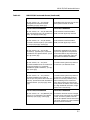
CsEvFormat/Event000d0101
CsPCause/Prob000d0101
{d "%w- %d %m-, %Y - %T"} Port {I 3} on
module in slot {I 1} of {m} ({t}), has
segmented. (event [{e}])
Cabling problem of extremely high rates
of traffic on the segment the port is
attached to.
CsEvFormat/Event000d0102
CsPCause/Prob000d0102
{d "%w- %d %m-, %Y - %T"} Port {I 3} on
module in slot {I 1} of {m} ({t}), has
unsegmented. (event [{e}])
1) A cable or termination fault has been
corrected. 2) Unsegmenting also can occur
on a port that previously was not in use.
CsEvFormat/Event000d0103
CsPCause/Prob000d0103
{d "%w- %d %m-, %Y - %T"} Network
A device supporting link integrity, fiber
configuration change reported by {m} ({t}). optic or twisted pair, has made a valid
Device linked to port {I 3} on module in
connection (link) to this port.
slot {I 1}. (event [{e}])
CsEvFormat/Event000d0104
CsPCause/Prob000d0104
{d "%w- %d %m-, %Y - %T"} Network
1) A device previously linked with this
configuration change reported by {m} ({t}). port has been removed or powered down.
Device previously linked to port {I 3} on
2) The cable segment has a fault.
module in slot {I 1} has ceased to transmit
link integrity pulse. (event [{e}])
Event and Alarm Messages
4-2
MRXI-22/24
Management Module Guide
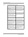
MRXI-22/24 Events and Alarms
Table 4-1.
MRXI-22/24 Events and Alarms (Continued)
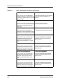
CsEvFormat/Event000d0105
CsPCause/Prob000d0105
{d "%w- %d %m-, %Y - %T"} New source
1) The device is new. 2) The device has
address {X 5}, is detected on {m} ({t}), port been powered up but has not transmitted
{I 3} of module in slot {I 1}. (event [{e}])
a packet with the aging time period.
CsEvFormat/Event000d0106
CsPCause/Prob000d0106
{d "%w- %d %m-, %Y - %T"} Source
address {X 5}, has timed out on port {I 3}
of the module in slot {I 1} of {m} ({t}).
(event [{e}])
A device linked or not linked to this port
has not transmitted a packet during the
aging time period, and has been removed
from the source address table of the
device.
CsEvFormat/Event000d0107
CsPCause/Prob000d0107
{d "%w- %d %m-, %Y - %T"} Device
A module within this hub has been
configuration change reported by {m} ({t}). removed or has failed.
The module in slot {I 1} has been removed.
(event [{e}])
CsEvFormat/Event000d0108
CsPCause/Prob000d0108
{d "%w- %d %m-, %Y - %T"} Device
A module has been inserted into this hub.
configuration change reported by {m} ({t}),
An (EPIM) has been inserted into slot {I 1}
of the MMAC. (event [{e}])
CsEvFormat/Event000d0109
CsPCause/Prob000d0109
{d "%w- %d %m-, %Y - %T"} Network
configuration change reported by {m} ({t}).
Port {I 3} in slot {I 1} has failed
redundancy polling and has switched to a
backup port. (event [{e}])
1) The device(s) have failed or have been
powered down. 2) A cable fault from the
active port to the polled device has
occurred.
CsEvFormat/Event000d010a
CsPCause/Prob000d010a
{d "%w- %d %m-, %Y - %T"} Network
configuration change reported by {m} ({t}).
Port {I 3} in slot {I 1} has now become
active as the result of a redundancy poll
failure. (event [{e}])
The polled device has been communicated
with via a backup port and the port is now
active. The other ports in this redundant
circuit are now designated as backup and
are turned off to prevent data loops on the
network.
CsEvFormat/Event000d010b
CsPCause/Prob000d010b
{d "%w- %d %m-, %Y - %T"} Redundancy The cable segment connected to the port
diagnostics of {m} ({t}), indicate that the
has a cable fault.
redundant link for module {I 1}, port {I 3}
has failed. (event [{e}])
9030751 E7
Event and Alarm Messages
4-3
MRXI-22/24 Events and Alarms
Table 4-1.
MRXI-22/24 Events and Alarms (Continued)
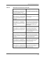
CsEvFormat/Event000d010f
CsPCause/Prob000d010f
{d "%w- %d %m-, %Y - %T"} User defined The device(s) attached to this module may
traffic threshold - {I 1} packets within {I 3} have an application which requires a
seconds, exceeded on module {I 5} of {m}
large amount of network bandwidth.
({t}). (event [{e}])
CsEvFormat/Event000d0110
CsPCause/Prob000d0110
{d "%w- %d %m-, %Y - %T"} Error
1) A malfunctioning device is present on
threshold exceeded. An error threshold, of this module. 2) A cable fault exists.
{I 1}% of total packets in {I 5} seconds,
exceeded on module in slot {I 7}. (event
[{e}])
CsEvFormat/Event000d0111
CsPCause/Prob000d0111
{d "%w- %d %m-, %Y - %T"} Collision
Collisions are caused by many nodes
threshold exceeded. The number of
contending for the network or cabling
collisins per total packets within the time faults.
base of {I 3} seconds has been exceeded on
the module in slot {I 5} of {m} ({t}). (event
[{e}])
CsEvFormat/Event000d0112
CsPCause/Prob000d0112
{d "%w- %d %m-, %Y - %T"} Traffic
The device(s) attached to this port may
threshold, {I 1} packets per {I 3} seconds, have an application which requires a
exceeded on port {I 7} on module in slot {I large amount of network bandwidth.
5} of {m} ({t}). (event [{e}])
CsEvFormat/Event000d0113
CsPCause/Prob000d0113
{d "%w- %d %m-, %Y - %T"} Error
threshold exceeded. An error threshold, of
{I 1}% of total packets in {I 5} seconds,
exceeded on port {I 9} on module in slot {I
7} of {m} ({t}). (event [{e}])
1) The device(s) attached to this port could
have a hardware failure where it
transmits invalid packets. 2) The cable
segment attached to this port may have a
problem.
CsEvFormat/Event000d0114
CsPCause/Prob000d0114
{d "%w- %d %m-, %Y - %T"} Collision
threshold exceeded. The number of
collisins per total packets within the time
base of {I 3} seconds has been exceeded on
port {I 7} on module in slot {I 5} of {m} ({t}).
(event [{e}])
1) The device(s) attached to this port may
have an adapter card problem which
causes them to transmit without
regarding network availability. 2) A cable
problem may exist.
Event and Alarm Messages
4-4
MRXI-22/24
Management Module Guide
MRXI-22/24 Events and Alarms
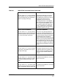
Table 4-1.
MRXI-22/24 Events and Alarms (Continued)
CsEvFormat/Event000d0115
CsPCause/Prob000d0115
{d "%w- %d %m-, %Y - %T"} Port Topology
type changed. Port {I 3} of module in slot
{I 1} has changed from {T PrtTopoStatus
5} port on {m} ({t}). (event [{e}])
The number of addresses in the source
address table has changed. If three or
more addresses are learned on a port for
one aging time period, the port is
designated as a trunk port. A port
connecting two hubs or a coax segment
with multiple taps are examples of trunk
ports. If a port has one address in the
source address table for one aging time,
the port is designated as a station port.
An example of a station port would be a
twisted pair "home run" to a PC.
CsEvFormat/Event000d0117
CsPCause/Prob000d0117
{d "%w- %d %m-, %Y - %T"} Port security
violation has occurred, MAC address {X 5}
has been detected on port {I 3} of module
in slot {I 1} of {m} ({t}). (event [{e}])
This event is only generated when the
hub has port locking enabled. When a hub
is locked, the source MAC addresses are
learned on each port. When a port detects
an attached device has changed its
address, the device will note that the new
address is not in the source address table.
This will disable and lock the port, which
then transmits this trap. This trap would
be generated if an adapter were replaced
or if an intruder attempted to access the
network.
CsEvFormat/Event000d0118
CsPCause/Prob000d0118
{d "%w- %d %m-, %Y - %T"} Port violation The network administrator has located
reset, port {I 3} of module in slot {I 1} of
the offending device that caused the port
{m} ({t}). (event [{e}])
violation, and has re-enabled the port for
use by the original network address for
that port.
CsEvFormat/Event000d0119
CsPCause/Prob000d0119
{d "%w- %d %m-, %Y - %T"} Environment 1) A module may be defective. 2) A fan has
Temperature Warm condition for module failed in the chassis.
in slot {I 1} reported by {m} ({t}). (event
[{e}])
CsEvFormat/Event000d011a
CsPCause/Prob000d011a
{d "%w- %d %m-, %Y - %T"} Environment 1) A module may be defective. 2) A fan has
Temperature Hot condition for module in failed in the chassis.
slot {I 1} reported by {m} ({t}). (event [{e}])
9030751 E7
Event and Alarm Messages
4-5
MRXI-22/24 Events and Alarms
Table 4-1.
MRXI-22/24 Events and Alarms (Continued)
CsEvFormat/Event000d011b
CsPCause/Prob000d011b
{d "%w- %d %m-, %Y - %T"} Environment 1) The power supply may be defective. 2)
Voltage Low condition has been detected An AC power failure has occurred into the
by power supply in slot {I 1} of {m} ({t}).
power supply module.
(event [{e}])
CsEvFormat/Event000d011c
CsPCause/Prob000d011c
{d "%w- %d %m-, %Y - %T"} Environment A chassis or cooling system problem at
Temperature Normal condition for
this device's location has been corrected.
module in slot {I 1} reported by {m} ({t}).
(event [{e}])
CsEvFormat/Event000d011d
CsPCause/Prob000d011d
{d "%w- %d %m-, %Y - %T"} Environment
Voltage Normal, all power supply voltages
have returned to NORMAL for {m} ({t}).
(event [{e}])
The problem with the power supply
module or AC power feed has been
corrected and the unit is now functioning
normally.
CsEvFormat/Event000d011e
CsPCause/Prob000d011e
{d "%w- %d %m-, %Y - %T"} A fan in the
1) One or more fans in the fan tray
system's chassis has failed or is operating assembly have failed. 2) The fan tray has
at an abnormal RPM rate, has been
been removed.
detected by {m} ({t}). (event [{e}])
CsEvFormat/Event000d011f
CsPCause/Prob000d011f
{d "%w- %d %m-, %Y - %T"} A fan in the
system's chassis has resumed normal
operation, has been detected by {m} ({t}).
(event [{e}])
The problem previously detected with the
fan assembly has been corrected and the
unit is now functioning normally.
CsEvFormat/Event000d0121
CsPCause/Prob000d0121
{d "%w- %d %m-, %Y - %T"} Broadcast
The broadcast (packets per time interval)
threshold exceeded {I 1} total packets in {I threshold has been exceeded for the given
3} seconds on the module in slot {I 5} of
module.
{m} ({t}). (event [{e}])
CsEvFormat/Event000d0122
CsPCause/Prob000d0122
{d "%w- %d %m-, %Y - %T"} Broadcast
The broadcast (packets per time interval)
threshold exceeded {I 1} total packets in {I threshold has been exceeded for the given
3} seconds on port {I 7} on the module in port.
slot {I 5} of {m} ({t}). (event [{e}])
CsEvFormat/Event000d0125
CsPCause/Prob000d0125
{d "%w- %d %m-, %Y - %T"} System
Voltage Low condition has been detected
by {m} ({t}). (event [{e}])
1) The power supplies are failing. 2) There
is not enough power available to the host
modules.
Event and Alarm Messages
4-6
MRXI-22/24
Management Module Guide
MRXI-22/24 Events and Alarms
Table 4-1.
MRXI-22/24 Events and Alarms (Continued)
CsEvFormat/Event000d0126
CsPCause/Prob000d0126
{d "%w- %d %m-, %Y - %T"} System
Voltage Normal condition has been
detected by {m} ({t}). (event [{e}])
The problem with the internal 5 volt line
of the system has been corrected.
CsEvFormat/Event000d0127
CsPCause/Prob000d0127
{d "%w- %d %m-, %Y - %T"} An EPIM has An Ethernet Port Interface Module
been removed from port {I 3} on module in (EPIM) has been physically removed.
slot {I 1} of {m} ({t}). (event [{e}])
CsEvFormat/Event000d0128
CsPCause/Prob000d0128
{d "%w- %d %m-, %Y - %T"} An (EPIM)
An Ethernet Port Interface Module
has been inserted into port {I 3} on module (EPIM) has been physically inserted.
in slot {I 1} of {m} ({t}). (event [{e}])
CsEvFormat/Event000d0129
CsPCause/Prob000d0129
{d "%w- %d %m-, %Y - %T"} Traffic
threshold, {I 1} packets per {I 3} seconds,
exceeded on the repeater network {I 5} of
{m} ({t}). (event [{e}])
The device(s) attached to this channel
may have an application level problem.
The attached devices may be operating
properly, but the application requires a
large amount of network bandwidth.
CsEvFormat/Event000d0130
CsPCause/Prob000d0130
{d "%w- %d %m-, %Y - %T"} Error
1) A malfunctioning device is present on
threshold exceeded. An error threshold, of this channel. 2) A cable fault exists.
{I 1}% total packets in {I 5} seconds,
exceeded on repeater network {I 7} of {m}
({t}). (event [{e}])
CsEvFormat/Event000d0131
CsPCause/Prob000d0131
{d "%w- %d %m-, %Y - %T"} Collision
threshold exceeded. The number of
collisins per total packets within the time
base of {I 3} seconds has been exceeded on
repeater network {I 5} of {m} ({t}). (event
[{e}])
1) A malfunctioning device is present on
this channel. 2) A cable fault exists. 3)
Collisions are usually caused by many
nodes contending for the network. As
traffic rates increase, the collision rate
usually follows. Therefore, if this channel
has a high bandwidth utilization, a high
collision rate is not unlikely.
CsEvFormat/Event000d0132
CsPCause/Prob000d0132
{d "%w- %d %m-, %Y - %T"} Network port The network administrator has changed
security is {T LockStatus 1} on repeater
the status of port locking for this repeater
network {I 3} of {m} ({t}). (event [{e}])
channel. The security feature locks all
ports on this repeater channel so that only
a valid user already in the source address
table can access the network.
9030751 E7
Event and Alarm Messages
4-7
MRXI-22/24 Events and Alarms
Table 4-1.
MRXI-22/24 Events and Alarms (Continued)
CsEvFormat/Event000d0133
CsPCause/Prob000d0133
{d "%w- %d %m-, %Y - %T"} Broadcast
The broadcast (packets per time interval)
threshold exceeded {I 1} total packets in {I threshold has been exceeded for the
3} seconds on repeater network {I 5} of {m} repeater.
({t}). (event [{e}])
CsEvFormat/Event000d0135
CsPCause/Prob000d0135
{d "%w- %d %m-, %Y - %T"} Port Security A change in the lock status for a
Status is {T LockStatus 3} for port #{I 2 }, particular port has occurred.
located in port group #{I 1} of {m} ({t}).
(event [{e}])
CsEvFormat/Event000d0136
CsPCause/Prob000d0136
{d "%w- %d %m-, %Y - %T"} Device
A module has been inserted into this hub.
configuration change reported by {m} ({t}).
The module in slot {I 1} has been inserted.
CsEvFormat/Event000d0137
CsPCause/Prob000d0137
{d "%w- %d %m-, %Y - %T"} Alternate
Path Repeater Management has been
enabled for {m} of type {t} Network
Address Synchronized to {O 1}. - (event
[{e}])
Alternate Path Repeater Management
functionality has been enabled for this
repeater model.
CsEvFormat/Event000d0138
CsPCause/Prob000d0138
{d "%w- %d %m-, %Y - %T"} Alternate
Path Repeater Management has been
enabled for {m} of type {t} No Network
Address Syncronization. - (event [{e}])
Alternate Path Repeater Management
functionality has been enabled for this
repeater model.
CsEvFormat/Event000d0139
CsPCause/Prob000d0139
{d "%w- %d %m-, %Y - %T"} Alternate
Path Repeater Management has been
disabled for {m} of type {t} Network
Address Syncronized to {O 1}. - (event
[{e}])
Alternate Path Repeater Management
functionality has been disabled for this
repeater model.
CsEvFormat/Event000d013a
CsPCause/Prob000d013a
{d "%w- %d %m-, %Y - %T"} Alternate
Path Repeater Management has been
disabled for {m} of type {t} No Network
Address Syncronization. - (event [{e}])
Alternate Path Repeater Management
functionality has been disabled for this
repeater model.
Event and Alarm Messages
4-8
MRXI-22/24
Management Module Guide
MRXI-22/24 Events and Alarms
Table 4-1.
MRXI-22/24 Events and Alarms (Continued)
CsEvFormat/Event000d013b
CsPCause/Prob000d013b
{d "%w- %d %m-, %Y - %T"} Alternate
Router Redundancy for the managing
Path Repeater Management has activated device model has probably been activated.
for {m} of type {t} Network Address
changed from {O 1} to {O 2}. - (event [{e}])
CsEvFormat/Event000d1139
CsPCause/Prob000d1139
{d "%w- %d %m-, %Y - %T"} Port Security The status of the secure state for a specific
Status is {T SecureState 3} for port #{I 2 }, port has changed.
located in port group #{I 1} of {m} ({t}).
(event [{e}])
CsEvFormat/Event000d113a
CsPCause/Prob000d113a
{d "%w- %d %m-, %Y - %T"} Network
Learning Status is {T LearnState 2} for
the network interface #{I 1} of {m} ({t}).
(event [{e}])
Network learning has been reset. When
learning is reset, all secure addresses on
each port, within the network, will be
deleted and ports will learn source
addresses again.
CsEvFormat/Event000d113b
CsPCause/Prob000d113b
{d "%w- %d %m-, %Y - %T"} Port Group
Learning Status is {T LearnState 2} for
the port group #{I 1} of {m} ({t}). (event
[{e}])
A port group's learning has been reset.
When learning is reset, all secure
addresses on each port, within a port
group, will be deleted and ports will learn
source addresses again.
CsEvFormat/Event000d113c
CsPCause/Prob000d113c
{d "%w- %d %m-, %Y - %T"} Port Learning
Status is {T LearnState 3} for the port #{I
2}, located in port group {I 1} of {m} ({t}).
(event [{e}])
A port's learning has been reset. When
learning is reset, all secure addresses on
the port will be deleted and the port will
learn source addresses again.
CsEvFormat/Event000d113d
CsPCause/Prob000d113d
{d "%w- %d %m-, %Y - %T"} Network
Network learning mode has changed
Learning Mode is {T LearnMode 2} for the between one-time learn mode and
network interface #{I 1} of {m} ({t}). (event continuous learn mode.
[{e}])
CsEvFormat/Event000d113e
CsPCause/Prob000d113e
{d "%w- %d %m-, %Y - %T"} Port Group
A port group's learning mode has changed
Learning Mode is {T LearnMode 2} for the between one-time learn mode and
port group #{I 1} of {m} ({t}). (event [{e}])
continuous learn mode.
9030751 E7
Event and Alarm Messages
4-9
MRXI-22/24 Events and Alarms
Table 4-1.
MRXI-22/24 Events and Alarms (Continued)
CsEvFormat/Event000d113f
CsPCause/Prob000d113f
{d "%w- %d %m-, %Y - %T"} Port Learning A port's learning mode has changed
Mode is {T LearnMode 3} for the port #{I between one-time learn mode and
2}, located in port group {I 1} of {m} ({t}).
continuous learn mode.
(event [{e}])
CsEvFormat/Event00010810
CsPCause/Prob00010810
{d "%w- %d %m-, %Y - %T"} RMON rising
threshold trap received from model {m} of
type {t}. AlarmIndex {I 1}, AlarmVariable
{O 2}, AlarmSampleType {I 3},
AlarmValue {I 4} and
AlarmRisingThreshold {I 5}. (event [{e}])
1) The current sampled value of a user
selected statistic is greater than or equal
to the alarm rising threshold and the
value at the last sampling interval was
less than the threshold.
CsEvFormat/Event00010811
CsPCause/Prob00010811
{d "%w- %d %m-, %Y - %T"} RMON falling
threshold trap received from model {m} of
type {t}. AlarmIndex {I 1}, AlarmVariable
{O 2}, AlarmSampleType {I 3},
AlarmValue {I 4} and
AlarmFallingThreshold {I 5}. (event [{e}])
1) The current sampled value of a user
selected statistic is less than or equal to
the alarm falling threshold and the value
at the last sampling interval was greater
than the threshold.
CsEvFormat/Event00010812
CsPCause/Prob00010812
{d "%w- %d %m-, %Y - %T"} RMON packet 1) A packet has matched the specified
match trap received from model {m} of
criterion for capture.
type {t}. Channel description: {S 3}.
Channel had {I 2} matches. (event [{e}])
CsEvFormat/Event00830000
No Probable cause message.
{d "%w- %d %m-, %Y - %T"} DLM
LostContact trap for Destination Address
{O 1}, Owner Address {O 2} from {t} device,
named {m}. (event [{e}])
CsEvFormat/Event00830001
No Probable cause message.
{d "%w- %d %m-, %Y - %T"} DLM
Threshold Trap for Destination Address
{O 1}, Owner {O 2}, OID sequence {I 3},
OID Object {O 4} from {t} device, named
{m}. (event [{e}])
CsEvFormat/Event00830002
No Probable cause message.
{d "%w- %d %m-, %Y - %T"} DLM
ReestabContact Trap for Destination
Address {O 1}, Owner Address {O 2} from
{t} device, named {m}. (event [{e}])
Event and Alarm Messages
4-10
MRXI-22/24
Management Module Guide
MRXI-22/24 Events and Alarms
Table 4-1.
9030751 E7
MRXI-22/24 Events and Alarms (Continued)
CsEvFormat/Event000d1101
CsPCause/Prob000d1101
{d "%w- %d %m-, %Y - %T"} AC Utility
Line Failure. The AC power to the UPS
monitored by {m} ({t}) is offline. (event
[{e}])
The UPS is now operating on battery
backup and the utility voltage is not
within a safe-operating range for your
equipment.
CsEvFormat/Event000d1102
CsPCause/Prob000d1102
{d "%w- %d %m-, %Y - %T"} AC Utility
Line Recovery. The AC power to the UPS
monitored by {m} ({t}) is back online.
(event [{e}])
AC Power has been restored to the UPS.
The UPS is now operating normally and
that power is present at the outlets.
CsEvFormat/Event000d1103
CsPCause/Prob000d1103
{d "%w- %d %m-, %Y - %T"} Low Battery
Condition. The battery in the UPS
monitored by {m} ({t}) is in a low
condition. (event [{e}])
Power loss.
CsEvFormat/Event000d1104
CsPCause/Prob000d1104
{d "%w- %d %m-, %Y - %T"} Low Battery
Recovery. The battery in the UPS
monitored by {m} ({t}) has re-charged its
battery above the low-battery point.
(event [{e}])
Power has been restored.
CsEvFormat/Event000d1105
CsPCause/Prob000d1105
{d "%w- %d %m-, %Y - %T"} Abnormal
Condition. The UPS monitored by {m} ({t})
has entered an abnormal condition, such
as an overload or trip on low battery.
(event [{e}])
1) Overload Condition: Too many devices
are plugged into the UPS. 2) UPS Initial
Power Up 3) Trip on Low Battery: The
UPS has lost AC Power and the Battery is
at a Low Condition.
CsEvFormat/Event000d1106
CsPCause/Prob000d1106
{d "%w- %d %m-, %Y - %T"} Abnormal
Condition Recovery. The UPS monitored
by {m} ({t}) has recovered from an
abnormal condition. (event [{e}])
1) Power has been restored. 2) Load has
stabilized to within specifications.
CsEvFormat/Event000d1107
CsPCause/Prob000d1107
{d "%w- %d %m-, %Y - %T"} UPS Shutting
Down. The UPS monitored by {m} ({t}) has
been ordered to shut itself, or the load, off
over the serial line. (event [{e}])
1) Discharged Battery: Battery
discharged due to an extended power
outage. 2) Overload Condition: An
overload condition has been detected
while the UPS was operating on battery.
Event and Alarm Messages
4-11
MRXI-22/24 Events and Alarms
Event and Alarm Messages
4-12
MRXI-22/24
Management Module Guide
Index
A
Accessing
the Device
Configuration View 3-2
Admin Status 3-3
Administrative Status 3-9
Ageing Interval 3-5
Alarm
Configuration 3-6, 3-10
Messages 4-1
Alignment 3-7
B
Bandwidth 3-3
Basic
Community String 3-4
Board Map 3-8
Board Number 3-13
Broadcast
Alarm 3-11
Condition 3-11
Alarms 3-7
Threshold 3-7, 3-11
CRC 3-7
Cyclical Redundancy Checks 3-7
D
Date 3-2
Description 3-3
Device
Name 3-2
View 2-1
Device Configuration Information 3-2
Device Configuration View 3-2
Device Icon 2-3
Device Icon Subviews Menu 2-4
Device Identification Labels 2-4
Device Number 2-4
Device Type 2-4
Device Views
Chassis 2-2
documentation
organization ix
DownLoad
Application 3-2
E
C
Change Time 3-4
Collision
Alarm 3-10
Condition 3-11
Alarms 3-6
Threshold 3-7, 3-11
Component Table 3-2
Configuration View
Device 3-1
Module 3-1
Port 3-1
Repeater 3-1
Source Address 3-1
Contact Status 3-2
Conventions x
EPIM 1-1
Error
Alarm 3-11
Condition 3-11
Alarms 3-7
Source 3-7, 3-11
Threshold 3-7, 3-11
Event
Messages 4-1
9030751 E7
1
F
N
Find
Source Address 3-12
Firmware Revision 3-2
Name 3-3, 3-4
Network
Port 3-5
Network Address 3-12
Network Port
Security 3-5
No_Resource 3-7
Notice v
Number of Interfaces 3-3
G
Generic View 3-1
Banner 3-2
Getting Help xi
Giants 3-7
O
H
Hardware Revision 3-2
HubCSIMRXi 1-2
I
ID 3-3, 3-4
Interface
Configuration Table 3-3
L
Link
Status 3-9
Traps 3-10
Link Traps 3-6
M
MAC Address 3-2
Management Module Definition 1-1
Manages 3-8
Model Name 3-12
Module
Management 3-8
Ports 3-9
Source Address Table
View 3-12
Module Configuration View 3-8
Module Source Address Table 3-12
MRXI-22/24 Component Table View 3-3
Index
2
OOW_Colls 3-7
Oper Status 3-3
Operational Status 3-9
P
P. Size 3-4
Phy Address 3-3
Port
Count 3-5, 3-8
ID 3-9
Management 3-9
Number 3-13
On 3-5, 3-8
Operational 3-5, 3-9
Source Address Table View 3-13
Port Configuration View 3-8
Port Number 2-5
Port Packet Rate 2-6
Port Status Label 2-6
Q
Q. Length 3-4
R
Reconfigure Router Addresses 3-4
Related Reading x, xi
Repeater
Management 3-5
Repeater Configuration View 3-4
Restricted Rights Notice vi
RJ-45 1-1
Runts 3-7
MRXI-22/24
Management Module Guide
S
Segmentation
Status 3-9
Traps 3-10
Segmentation Traps 3-6
Set Topological State 3-9
Source Address 3-12
Board/Port Location View 3-12
Source Address Management 3-5
Source Address Traps 3-6, 3-10
Source Addressing 3-12
SPECTRUM
Portable Management Application 1-6
SPECTRUM Model Type 1-2
SPECTRUM Views Roadmap 1-5
SPMA
Application View 1-6
SPMA Applications 1-6
SPMA Support 1-6
Status 3-3
T
TCP/IP Based Networks xi
Timebase 3-6
Topological State 3-9
Trademarks v
Traffic
Alarm 3-10
Condition 3-10
Alarms 3-6
Threshold 3-6, 3-10
Trap
Configuration 3-10
Trap Configuration 3-6
Type 3-3
V
Version 3-4
Virus Disclaimer vi
9030751 E7
Index
3