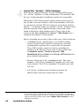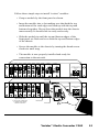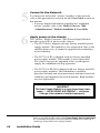
1
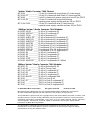
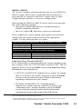
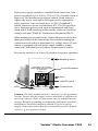
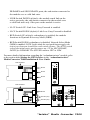
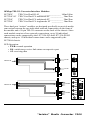
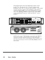
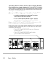
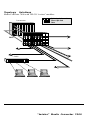
JULY 1999
LE7306A
LE7312A-R2
LE7312A-PS-R2
™
“twister”
MEDIA CONVERTER 7000
100 BASE
10 BASE
PWR
10 BASE
PWR
100 BASE
100 BASE
PWR
PWR
100 BASE
PWR
100 BASE
PWR
100 BASE
100 BASE
PWR
100 BASE
“redundant twister”
PWR
“redundant twister”
SW
RESET
TP
TP
LK
LK
M
A
I
N
AT
AT
LK
P
R
I
M
M
AT
R
X
LK
BNC
AT
AT
T
X
TX
R
X
M
M
T
X
R
X
LK
LK
S
M
AT
T
X
R
X
LK
S
M
AT
T
X
AT
T
X
MAIN
LK
LK
AT
AT
AT
MAIN
PWR
LK
SW
AT
RESET
FX
LK
COL
TX
LK
FL
R
X
AT
LK
M
M
T
X
AT
S
E
C
R
X
LK
R
X
LK
S
M
AT
T
X
SECONDARY
FX
R
X
R
X
LK
AT
T
X
LK
AT
T
X
PWR
LK
SW
DISCONNECT ALL POWER
SOURCES BEFORE SERVICING
AC IN 90-250V
50/60Hz 1A
AT
RESET
PRIMARY
LK R
X
AT
T
X
R
X
T
X
SECONDARY
LK
PRIMARY
LK R
X
AT
T
X
R
X
AT
T
X
LK
AT
SEC
POWER ACTIVE
100 BASE
10 BASE
PWR
10 BASE
PWR
100 BASE
PWR
100 BASE
100 BASE
PWR
PWR
100 BASE
PWR
100 BASE
100 BASE
PWR
100 BASE
“redundant twister”
PWR
“redundant twister”
SW
RESET
TP
M
A
I
N
LK
LK
R
X
LK
AT
AT
AT
M
M
AT
LK
P
R
I
TP
LK
BNC
AT
AT
T
X
TX
R
X
M
M
T
X
R
X
R
X
LK
LK
S
M
AT
R
X
LK
S
M
AT
T
10 BASE
X
LK
LK
LK
AT
AT
AT
LK
P
R
I
PWR
T
10 BASE
X
PWR
TP
TP
PWR
LK
AT
SW
AT
R
X
LK
AT
R
X
LK
S
M
R
X
LK
AT
T
100 BASE
X
T
100 BASE
X
R
X
LK
R
X
M
M
AT
PWR
PWR
M
M
T
X
COL
T
X
R
X
LK
AT
T
100 BASE
X
AT
R
X
S
M
T
X
LK
AT
R
X
S
M
T
X
T
X
LK
SW
PRIMARY
LK R
X
AT
T
X
SECONDARY
LK
R
X
AT
AT
T
X
PRIMARY
LK R
X
AT
T
X
DISCONNECT ALL POWER
SOURCES BEFORE SERVICING
AC IN 90-250V
50/60Hz 1A
DISCONNECT ALL POWER
SOURCES BEFORE SERVICING
AC IN 90-250V
50/60Hz 1A
POWER ACTIVE
POWER ACTIVE
LK
AT
PWR
TX
LK
LK
AT
AT
FX
LK
AT
R
X
PWR
RESET
SECONDARY
FX
FL
BNC
MAIN
LK
AT
RESET
T
X
AT
S
E
C
AT
MAIN
LK
AT
FX
T
COL100 BASE
X
PWR
SW
RESET
M
A
I
N
TX
LK
FL
LK
SEC
LK
M
M
T
X
AT
S
E
C
R
X
LK
AT
R
X
T
X
DISCONNECT ALL POWER
SOURCES BEFORE SERVICING
AC IN 90-250V
50/60Hz 1A
LK
AT
SEC
POWER ACTIVE
Installation & User Guide
CUSTOMER
SUPPORT
INFORMATION
Order toll-free in the U.S. 24 hours, 7 A.M. Monday to midnight Friday: 877-877-BBOX
FREE technical support, 24 hours a day, 7 days a week: Call 724-746-5500 or fax 724-746-0746
Mail order: Black Box Corporation, 1000 Park Drive, Lawrence, PA 15055-1018
Web site: www.blackbox.com • E-mail: [email protected]
“twister” Media Converter 7000 Chassis:
LE7300A ____________ 17-slot 2U chassis with single fixed AC power supply
LE7300A-PS _________ 16-slot 2U chassis with dual fixed AC power supplies
LE7306A ____________ 6-slot 2U chassis with power supply and one 50-pin TELCO
LE7312A-R2 _________ 12-slot 2U chassis with single load-sharing
capable power supply module and two 50-pin TELCO
LE7312A-PS-R2 _______ 12-slot 2U chassis with dual (2) load-sharing
capable power supply modules and two 50-pin TELCO
100Mbps “twister” Media Converter 7000 Modules:
LH7416C-SX-R2 ______ RJ-45 to SX multimode SC
LH7416C-SXST-R2 _____ RJ-45 to SX multimode ST
LH7402C-TX-R2 ______ RJ-45 to Redundant TX
LH7403C-MMSC-R2 ___ RJ-45 to Redundant FX multimode SC
LH7404C-SMSC-R2 ____ RJ-45 to Redundant FX singlemode SC
LH7403C-MMST-R2 ___ RJ-45 to Redundant FX multimode ST
LH7403C-SMST-R2 ____ RJ-45 to Redundant FX singlemode ST
LH7420C-SCSC-R2 ____ FX multimode SC to FX singlemode SC
LH7420C-SCST-R2 ____ FX multimode SC to FX singlemode ST
LH7421C-STSC-R2 ____ FX multimode ST to FX singlemode SC
LH7421C-STST-R2 _____ FX multimode ST to FX singlemode ST
LH7414C-R2 _________ RJ-45 to FX multimode SC
LH7416C-R2 _________ RJ-45 to FX singlemode SC
LH7415C-R2 _________ RJ-45 to FX multimode ST
LH7416C-ST-R2 _______ RJ-45 to FX singlemode ST
LH7416C-40KM-R2 ___ RJ-45 to FX singlemode SC (40km)
10Mbps “twister” Media Converter 7000 Modules:
LE7402C-TX _________ RJ-45 to Redundant RJ-45
LE7313C-R2 _________ RJ-45 to Thinnet Coax
LE7313C-SC-R2 ______ RJ-45 to FL multimode SC
LE7314C-R2 _________ RJ-45 to FL multimode ST
LE7316C-R2 _________ RJ-45 to FL singlemode ST
LE7316C-MM-R2 _____ RJ-45 to FL multimode SMA
LE7302C ____________ TELCO to Dual RJ-45
LE7324C-SC _________ TELCO to Dual FL multimode SC
LE7324C ____________ TELCO to Dual FL multimode ST
LE7326C ____________ TELCO to Dual FL singlemode ST
© 1999 Black Box Corporation
All rights reserved.
Printed in USA.
Black Box and the Black Box logo are registered trademarks of Black Box Corporation.
All other trademarks appearing in this manual are the property of their owners.
This publication is protected by the copyright laws of the United States and other countries, with
all rights reserved. No part of this publication may be reproduced, stored in a retrieval system,
translated, transcribed, or transmitted, in any form, or by any means manual, electric, electronic,
electromagnetic, mechanical, chemical, optical or otherwise, without prior explicit written
permission of Black Box Corporation.
The information contained in this document is assumed to be correct and current. The
manufacturer is not responsible for errors or omissions and reserves the right to change
specifications at any time without notice.
Table of Contents
“twister”™ Media Converter 7000 Installation & User Guide
Introduction ................................................................................................... 5
Product Overview ........................................................................................... 5
Installation Guide .......................................................................................... 8
STEP 1: Unpacking the Chassis & Accessories ............................. 8
STEP 2: Mounting the Chassis ....................................................... 8
STEP 3: Setting the Switches and Jumpers .................................. 10
STEP 4: Installing “twister” 7000 Modules ................................. 12
STEP 5: Connecting to the Network ............................................ 14
STEP 6: Applying Power to the Chassis ...................................... 14
User Guide ................................................................................................... 17
“twister” 7000 Modules ............................................................... 18
100Mbps Specifications ................................................................ 19
“redundant twister” Modules .................................................... 20
MM-to-SM FX Modules .......................................................... 22
TX-to-FX Modules ................................................................... 23
10Mbps Specifications .................................................................. 24
“redundant twister” Module ...................................................... 25
Thinnet Coaxial BNC Module .................................................. 27
Fiber Optic Modules ................................................................. 28
TELCO .................................................................................... 29
Chassis Technical Specifications .................................................. 31
Operating Features of the Power Supply ...................................... 32
Power Supply Service Instructions .............................................. 33
Link Loss Carry Forward (LLCF) ................................................ 35
Straight/Cross Over RJ-45 Twisted-pair Cables .......................... 36
Topology Solutions ...................................................................... 37
“redundant twister” ................................................................... 37
singlemode-to-multimode ....................................................... 37
10/100 mixed environment ...................................................... 38
10/100 mixed environment with stand-alone “twisters” ......... 40
TELCO modules ...................................................................... 41
Product Safety, EMC and Compliance Statements ...................... 42
4
Introduction
Thank you for choosing the “twister”™ Media Converter 7000.
The “twister” Media Converter provides a cost-effective means of integrating a mixed media environment. The information in this guide helps you to
install and start using your “twister” Media Converter 7000.
Overview
Your “twister”™ Media Converter 7000 offers transparent media conversion and provides an effective means for integrating coax, Category 3, 4, or
5 twisted-pair and singlemode or multimode fiber optic LAN segments into
either switched or shared Ethernet and Fast Ethernet
environments. All “twister” solutions provide media conversion with a low
bit delay. The modules reliably convert all signal activity from one cable
medium to the other ensuring accurate data flow across the network.
These IEEE 802.3 and 802.3u compliant media converters are compatible
with Ethernet and Fast Ethernet devices from other leading network
technology providers. This increases the flexibility of network configurations by ensuring reliable data transmission in multi-vendor, as well as
mixed media, environments.
Whether you are updating or expanding your existing network, the
“twister”™ Media Converter 7000 supports a wide range of configuration
needs. Each chassis unit supports multiple 10 and 100Mbps media types—
via “twister” modules—in any combination. In addition, the “redundant
twister”™ modules and dual load-sharing power supplies provide redundancy for uninterrupted network operation. While the “twister” Media
Converter 7000 chassis support media conversion for any 7000 Module,
only certain modules will work in conjunction with the TELCO connector
on the back of these chassis. Please refer to the section in this User Guide
titled “twister” 7000 Modules for a complete description of each module.
The “twister” Media Converter 7000 offers front accessible network
connections for ease of installation and maintenance. For high density
implementations, the units have rear-mounted 50-pin TELCO connectors
that provide connection capability for up to six (6) “twister” modules each.
“twister” Media Converter 7000
5
The TELCO connection provides a convenient means of connecting to an
MDF-ready hub, switch or patch panel.
The “twister” Media Converter 7000 offers three models with TELCO
connectors. The LE7312A-PS-R2 is a 12-slot 2U chassis with dual 50-pin
TELCO connectors. This chassis is available with dual load-sharing power
supplies to ensure essential non-stop networking for high priority traffic
and business-critical applications. The LE7312A-R2 is a 12-slot 2U chassis
with a single power supply and dual 50-pin TELCO connectors. These
rack-mountable models fit standard 19” equipment racks and the 2U
chassis height provides housing for the maximum number of intelligent
“twister” modules. The LE7306A “twister” media converter, a
6-slot 2U chassis with a single power supply and a single 50-pin TELCO
connector, is designed for environments where the flexibility and functionality of a “twister” chassis is required but where a smaller number of slots
are needed. This unit is available with an optional wall-mountable bracket
for convenient attachment to a wall or other vertical surface.
The “twister” Media Converter 7000 provides the following key features:
• A Link Loss Carry Forward (LLCF) enable/disable switch is
installed on the modules* as an aid to troubleshooting a
remote connection. Refer to the section of this guide titled
Link Loss Carry Forward for more information.
•
An MDI-II/MDI-X switch is installed on all TP ports.**
•
Fused power on each module protects the rest of the modules
in the chassis from a short circuit. The power (PWR) LED
on an affected module does not illuminate if the fuse is blown.
•
Auto polarity support on all twisted-pair ports.
•
“redundant twister” modules can be configured to operate
in Dynamic Recovery Mode (DRM) to ensure session integrity
and increased uptime, or in Network Select Mode (NSM) to
redirect traffic and add security through link isolation.
* Link Loss Carry Forward (LLCF) functionality is not provided on the LE7313C-R2 (BNC) or the
LE73XXC (TELCO) modules.
** This is not applicable to the LE7302C (TELCO) module.
6
Related Documentation
Refer to the following documentation for additional specific information on
the “twister” Media Converter 7000:
• Media Converter 7000 “redundant twister”™ Modules
Installation & User Guide
• “twister”™ Media Converter 7000 Modules
Quick Reference
“twister” Media Converter 7000
7
Installation Guide
Follow the simple steps outlined in this section of the manual to install
and start using the “twister” Media Converter 7000 chassis.
1
Unpack the chassis and any accessories.
Check that the following components have been included:
• “twister” Media Converter 7000 chassis
• Power Cord (one each per power supply)
• Rackmounting Hardware
The following items are available separately:
• “twister” Modules
• Wall Mount Bracket and Hardware (LE7306A)
• Blank Panels for unused chassis slots
Your order has been provided with the safest possible packaging,
but shipping damage does occasionally occur. Inspect it carefully.
If you discover any shipping damage, notify the carrier and follow
their instructions for damage and claims. Save the original shipping
carton in case return or storage of the unit is necessary.
2
Mount the chassis in an appropriate location.
The LE7312A-PS-R2 and LE7312A-R2 chassis are designed to be
mounted in a standard 19-inch equipment rack. Use the
rackmounting hardware included with the unit to secure the
mounting brackets to the unit. Use the separate screws provided
with the equipment rack to mount the chassis on the rack. Be sure
that the mounting of the equipment in the rack does not impose a
hazardous condition due to uneven mechanical loading.
Caution. Elevated ambient conditions may occur in an enclosed
equipment rack or multi-rack assembly. Consideration should be
taken when installing the chassis to ensure that the exhaust fan at
the rear of the unit is not blocked—improper venting of the exhaust
fan may cause the unit to overheat.
TUV Compliance Note. For pluggable equipment, the socket outlet
must be installed near the equipment and be easily accessible.
Bei Geräten mit Steckanschluß muß die Steckdose nahe dem Gerät
angebracht und leicht zugänglich sein.
8
Installation Guide
Because of its smaller size, the LE7306A chassis can be placed on
any flat surface. To save space and keep the installation area
organized, use the optional wall mount bracket. Follow these
simple instructions and refer to the diagram below:
• Place the bracket up against the wall and use a pencil to mark
where the anchors will be placed. Be sure that the chassis will
be mounted in such a way that fully exposes the front panel
for access to the network and power connections and does not
block the rear exhaust fan.
• Secure the bracket to the wall using anchors with a minimum
proof load of 50lbs.
• Place the LE7306A inside of the bracket and secure the chassis
to the bracket with the hardware provided.
DISCONNECT ALL POWER
SOURCES BEFORE SERVICING
AC IN 90-250V
50/60Hz 1A
POWER ACTIVE
Use anchors with a
minimum proof load
of at least 50lbs.
“twister” Media Converter 7000
9
3
Set the Switches and Jumpers.
Locate the switches and jumpers.
The following illustrations show the orientation of the DIP
switches and LLCF jumpers for the 10Mbps and 100Mbps
“twister” modules.* These illustrations are generalized and not
specific to a particular module. Refer to the “redundant twister”
module diagrams in the User Guide section of this document for
more detailed information on the location and setting of the DIP
switches for these particular modules.
LLCF
Jumpers
JP1
MDI-X Position
3 2 1
Slide Switch
RJ-45
MDI-II Position (default)
This is a generalized diagram of a “twister”
10Mbps module (with the exception of the
LE7313C-R2 BNC or LE73XXC TELCO modules)
and is not specific to any particular module.
LLCF
Jumpers
3 OFF
2
1 ON
LLCF
MDI-X Position
Slide Switch
MDI-II Position (default)
This is a generalized diagram of a “twister”
100Mbps module (with the exception of the
LH740XC “redundant twister” modules) and is
not specific to any particular module.
* This is not applicable to the LE7313C-R2 (BNC) or the LE73XXC (TELCO) modules.
10
Installation Guide
RJ-45
MDI-II to MDI-X
All “twister” modules with twisted-pair ports* have an MDI-II to
MDI-X switch. This switch is positioned directly behind it’s
associated RJ-45 connector and allows simple setup in either
straight through (default) or crossover configurations.
When setting the MDI-II to MDI-X switch, observe the positioning of the following symbols:
• the parallel symbol (II) indicates a straight through or
parallel connection (default)
• the cross symbol (X) indicates a crossover connection.
These symbols are clearly marked on the printed circuit board.
Simply slide the switch in the direction of the appropriate
symbol. Use the following table as a guide:
A device that is wired straight through, needs one crossover connection:
If the cable is…
… the MDI-II to MDI-X Switch Setting should be
straight through
X
crossover
II
A device that is wired crossover, needs a parallel connection:
If the cable is…
… the MDI-II to MDI-X Switch Setting should be
straight through
II
crossover
X
Link Loss Carry Forward (LLCF)**
LLCF functionality is incorporated on all “twister” modules with
the exception of the LE7313C-R2 (BNC) and LE73XXC TELCO
modules. Refer to the User Guide section titled Link Loss Carry
Forward for more information.
• LE731XC and LH741XC modules have a jumper for setting
the LLCF. Refer to the module diagrams in the User Guide
section of this document for more detailed information
regarding configuration of this jumper.
• LH740XC and LE7402C-TX “redundant twister”
modules have a DIP switch for setting LLCF. Refer to the
“redundant twister” module diagrams in the User Guide
section of this document for more detailed information
regarding the location and setting of this DIP switch.
* This is not applicable to the LE7302C (TELCO) module.
** The LLCF default setting is: disabled. Link Loss Carry Forward (LLCF) functionality is not provided on
the LE7313C-R2 (BNC) or the LE73XXC (TELCO) modules.
“twister” Media Converter 7000
11
4
Install the “twister” 7000 Modules.
Each chassis supports multiple 10 and 100Mbps media types—
via “twister” modules—in any combination. The modules offer
the ease of plug-and-play installation and are hot-swappable.
While these 7000 Series chassis support media conversion for
any Media Converter Module, only certain modules will work
in conjunction with the TELCO connector on the back of these
chassis.* A complete listing of available “twister” modules and a
short description of the supported media conversion can be
found in the front of this product guide. Please refer to the
section in the User Guide titled “twister” 7000 Modules for a
complete description of each module.
Before installing any module, please make note of the following:
• “redundant twister” modules have a set of DIP switches
located on the module board for setting user-selectable
configurability options for several modes of operation.
These DIP switches must be set before installing the
modules in the chassis. Please refer to the section in the
“redundant twister” Media Converter 7000
Installation & User Guide titled Set the DIP Switches for
more detailed information.
• Because of the size of the “redundant twister” fiber optic
modules, each TX-to-redundant FX module uses two slots
in the chassis. The TX-to-redundant TX module uses only
one slot.
• All “twister” modules must be firmly secured to the
chassis before network connections are made.
*
12
Only the LE7302C, LE7324C-SC, LE7324C, AND LE7326C Modules will
work in conjunction with the TELCO connector on the back of these chassis.
Refer to the USER GUIDE section titled 10Mbps TELCO Modules for more
detailed information.
Installation Guide
Follow these simple steps to install “twister” modules:
• Grasp a module by the front panel as shown.
• Insert the module into a slot making sure that both the top
and bottom of the card edges are lined up with the top and
bottom slot guides. Do not force the module into the chassis
unnecessarily. It should slide in easily and evenly.
• Slide the module in until the top and bottom edges of the
front panel are flush and even with the top and bottom edges
of the chassis.
• Secure the module to the chassis by turning the thumb screw
clockwise until snug.
• The module is now properly installed and ready for
connection to the network.
100 BASE
10 BASE
10 BASE
PWR
PWR
100 BASE
PWR
100 BASE
100 BASE
PWR
PWR
100 BASE
PWR
100 BASE
100 BASE
PWR
100 BASE
“redundant twister”
PWR
“redundant twister”
SW
RESET
TP
TP
LK
LK
M
A
I
N
AT
AT
LK
P
R
I
LK
AT
LK
M
M
AT
T
X
BNC
LK
M
M
AT
T
X
TX
R
X
R
X
LK
AT
T
X
COL
TX
LK
M
M
AT
T
X
R
X
LK
S
M
AT
T
X
R
X
LK
S
M
AT
T
X
MAIN
LK
PWR
LK
AT
MAIN
LK
SW
AT
R
X
LK
S
M
AT
T
X
R
X
LK
AT
T
X
R
X
T
X
AT
PRIMARY
LK R
X
AT
T
X
R
X
LK
T
X
LK
SW
DISCONNECT ALL POWER
SOURCES BEFORE SERVICING
AC IN 90-250V
50/60Hz 1A
AT
RESET
SECONDARY
FX
PWR
AT
RESET
FX
LK
AT
R
X
FL
AT
S
E
C
R
X
SECONDARY
LK
PRIMARY
LK R
X
AT
T
X
R
X
AT
T
X
LK
AT
SEC
POWER ACTIVE
Card Guide
100 BASE
10 BASE
10 BASE
PWR
PWR
100 BASE
PWR
100 BASE
100 BASE
PWR
PWR
100 BASE
PWR
100 BASE
100 BASE
PWR
100 BASE
“redundant twister”
PWR
“redundant twister”
SW
RESET
TP
TP
LK
LK
M
A
I
N
AT
AT
LK
P
R
I
BNC
AT
M
M
LK
AT
R
X
M
M
T
X
LK
AT
R
X
M
M
T
X
TX
R
X
COL
T
X
TX
LK
LK
AT
AT
AT
AT
R
X
S
M
T
X
LK
AT
R
X
S
M
T
X
LK
AT
R
X
S
M
T
X
PWR
MAIN
LK
SW
LK
AT
R
X
T
X
LK
AT
R
X
T
X
LK
AT
R
X
T
X
SW
RESET
SECONDARY
FX
PWR
AT
RESET
FX
LK
MAIN
LK
FL
LK
AT
R
X
T
X
AT
S
E
C
LK
PRIMARY
LK R
X
AT
T
X
LK
R
X
AT
T
X
PRIMARY
LK R
X
AT
T
RESET X
PWR
SW
SECONDARY
SEC
R
X
T
X
Thumb Screw
IMPORTANT!
Tighten thumb screw
to secure each module firmly
to chassis before making
network connections.
LK
100 BASE
AT
DISCONNECT ALL POWER
SOURCES BEFORE SERVICING
AC IN 90-250V
50/60Hz 1A
“redundant twister”™
SECONDARY
LK
DISCONNECT ALL POWER
SOURCES BEFORE SERVICING
AC IN 90-250V
50/60Hz 1A
MAIN
AT
LK
AT
PRIMARY
LK R
X
AT
T
X
LK
AT
POWER ACTIVE
POWER ACTIVE
Blank Panel
Card Guide
“twister” Media Converter 7000
13
5
Connect to the Network.
To connect the individual “twister” modules to the network,
refer to the appropriate section in the the User Guide section of
this manual.
• For more detailed information regarding the “redundant
twister” module, refer to the Media Converter 7000
“redundant twister” Modules Installation & User Guide.
6
Apply power to the chassis.
The “twister” Media Converter 7000 Power Supply Module
provides up to 60W of power to the chassis.
• The LE7306A is shipped with one factory-installed power
supply module. This module is user replaceable. Due to the
smaller chassis size, it cannot be upgraded for redundancy
or load-sharing.
• The LE7312A-R2 is shipped with one factory-installed
power supply module. This module is user replaceable.
The chassis can also be upgraded with a second power
supply for redundant non-stop operation.
• The LE7312A-PS-R2 is shipped with two factory-installed
power supply modules. This redundancy capability
provides essential non-stop operation to maximize network
reliability and minimize network downtime. Both modules
are user replaceable.
IMPORTANT
The Power Supply Module is an open frame-type power
supply — LIVE VOLTAGES ARE PRESENT — and poses
a danger if the module is installed improperly. *
•
14
Refer to the USER GUIDE section titled Power Supply Service Instructions
for a complete description of the procedure to follow when replacing or
installing a Redundant Power Supply Module.
Installation Guide
Each power supply includes a standard North American 3-pin
power cord which is UL (USA), CSA or CUL (Canada) listed or
approved. For installation in regions outside North America,
replace the power cord with a cord approved by appropriate
safety agencies. Any cord must have a CEE-22 standard V
female connector on one end and meet IEC 320-030 specifications. European power cords must be harmonized and designated with a HAR marking on the outside of the cord jacket to
comply with the CENELEC Harmonized Document HD-21
When making power connections, connect the power cord to the
input jack located on the front of the chassis before making the
connection to the outlet or appropriate AC voltage source. If your
chassis is equipped with two power supply modules, simply
connect the individual power cords to separate power sources.
Be sure the switch is set to the ON position for proper operation.
Retaining Screw
DISCONNECT ALL POWER
SOURCES BEFORE SERVICING
AC IN 90-250V
50/60Hz 1A
Power Receptacle
Vent
ON/OFF Switch
LEDs
POWER ACTIVE
Thumb Screw
Caution. The fully loaded chassis is rated for 2A AC maximum
current. Ensure that the supply current available is sufficient to
power the chassis. Refer to front panel text for voltage/current
ratings. Reliable grounding of rackmount equipment should be
maintained. Particular attention should be given to power
supply connections other than direct connections to the branch
circuit (e.g. use of power strips).
“twister” Media Converter 7000
15
16
User Guide
This section contains mor e detailed user inf ormation regarding cer tain
oper ating features and maintenance instr uctions for your “twister”
Media Con verter 7000.
“twister” 7000 Modules
Media conversion provides a cost-effective means of integrating various
types of Ethernet and Fast Ethernet LAN segments.
All “twister” modules provide media conversion with a low bit delay. All
signal activity – including collision detection – is reliably propagated from
one cable medium to the other ensuring accurate data flow across the
network. Maximum segment lengths are supported on either side of the
device. Seamless operation in half-duplex or full-duplex environments
ensures interoperability with Ethernet and Fast Ethernet devices from other
leading network technology providers. This increases the flexibility of
network configurations by ensuring reliable data transmission in multivendor, as well as mixed media, environments.
An extensive line of plug-and-play, hot-swappable “twister” modules
support 10 or 100Mbps operation and provide a variety of connector
combinations for flexibility and adaptability.
“twister” Media Converter 7000
“twister” Media Converter 7000 Modules:
100Mbps “twister” Modules:
LH7416C-SX-R2 ______ RJ-45 to SX multimode SC
LH7416C-SXST-R2 ____ RJ-45 to SX multimode ST
LH7402C-TX-R2 ______ RJ-45 to Redundant TX
LH7403C-MMSC-R2 ___ RJ-45 to Redundant FX multimode SC
LH7404C-SMSC-R2 ___ RJ-45 to Redundant FX singlemode SC
LH7403C-MMST-R2 ___ RJ-45 to Redundant FX multimode ST
LH7403C-SMST-R2 ____ RJ-45 to Redundant FX singlemode ST
LH7420C-SCSC-R2 ____ FX multimode SC to FX singlemode SC
LH7420C-SCST-R2 ____ FX multimode SC to FX singlemode ST
LH7421C-STSC-R2 ____ FX multimode ST to FX singlemode SC
LH7421C-STST-R2 ____ FX multimode ST to FX singlemode ST
LH7414C-R2 _________ RJ-45 to FX multimode SC
LH7416C-R2 _________ RJ-45 to FX singlemode SC
LH7415C-R2 _________ RJ-45 to FX multimode ST
LH7416C-ST-R2 ______ RJ-45 to FX singlemode ST
LH7416C-40KM-R2 ___ RJ-45 to FX singlemode SC (40km)
10Mbps “twister” Modules:
LE7402C-TX _________ RJ-45 to Redundant RJ-45
LE7313C-R2 __________ RJ-45 to Thinnet Coax
LE7313C-SC-R2 ______ RJ-45 to FL multimode SC
LE7314C-R2 __________ RJ-45 to FL multimode ST
LE7316C-R2 __________ RJ-45 to FL singlemode ST
LE7316C-MM-R2 _____ RJ-45 to FL multimode SMA
LE7302C ____________ TELCO to Dual RJ-45
LE7324C-SC _________ TELCO to Dual FL multimode SC
LE7324C ____________ TELCO to Dual FL multimode ST
LE7326C ____________ TELCO to Dual FL singlemode ST
Caution. All “twister” modules must be firmly secured to the chassis
before network connections are made. Please refer to the section titled
Installing “twister” 7000 Modules for instructions on the proper
installation procedure.
18
User Guide
100Mbps “twister” 7000 Modules
Specifications
Data Rate _________________________________ 100Mbps half-duplex
__________________________________ 200Mbps full-duplex
Bit Delay ____________________________________________ < 40 bits
Twisted-Pair Interface
Connector _____________________________ Shielded RJ-45, 8-pin jack
Impedance ___________________________________ 100 Ohms nominal
Signal Level Output (differential) ______________________ .95 to 1.05V
Signal Level Input _____________________________ 350mV minimum
Supported Link Length ____________________________________ 100m
Cable Type ____________________________________ Category 5 UTP
Multimode Fiber Optic Interface
Connector ___________________________________________ ST or SC
RX Input Sensitivity _______________________ -31 dBm peak minimum
Output Power ___________________ -14 dBm to -23.5 dBm (50/125 µm)
______________________ -14 dBm to -20 dBm (62.5/125 µm)
Supported Link Length _______________________ up to 2km full duplex
Cable Type ______________________ 50/125, 62.5/125, 100/140 µm F/O
Singlemode Fiber Optic Interface
Connector ___________________________________________ ST or SC
RX Input Sensitivity _______________________ -31 dBm peak minimum
Output Power ______________________ -8 dBm to -15 dBm (9/125 µm)
Supported Link Length ______________________ up to 15km full duplex
Cable Type __________________ 8.3/125, 8.7/125, 9/125, 10/125 µm F/O
Singlemode Fiber Optic Interface — extended distance support
Connector ________________________________________________ SC
RX Input Sensitivity ___________________________ -35 dBm minimum
Output Power ________________________ 0 dBm to -5 dBm (9/125 µm)
Supported Link Length ______________________ up to 40km full duplex
Cable Type __________________ 8.3/125, 8.7/125, 9/125, 10/125 µm F/O
“twister” Media Converter 7000
100Mbps “redundant twister” 7000 Modules:
LH7402C-TX-R2
RJ-45 to Redundant RJ-45 ___________ 100m/100m
LH7403C-MMSC-R2 RJ-45 to Redundant FX multimode SC ___ 100m/2km
LH7404C-SMSC-R2 RJ-45 to Redundant FX singlemode SC __ 100m/15km
LH7403C-MMST-R2 RJ-45 to Redundant FX multimode ST ___ 100m/2km
LH7403C-SMST-R2 RJ-45 to Redundant FX singlemode ST __ 100m/15km
The “redundant twister” modules provide full redundant data paths for
Fast Ethernet devices. The modules incorporate a MAIN port, a PRIMARY
port and a SECONDARY port. The redundancy is provided between the
PRIMARY and SECONDARY ports.
LED Operation:
• PWR: normal operation
• SW: SECONDARY port active at some point; functions in
Dynamic Recovery Mode (DRM) only
• SECONDARY: port is active (PRIMARY is inactive)
• (MAIN) LK: receiving valid link
• (MAIN) AT: receiving data
• (PRIMARY) LK: receiving valid link
• (PRIMARY) AT: receiving data
• (SECONDARY) LK: receiving valid link
• (SECONDARY) AT: receiving data
DIP switch* settings:
• TX Switch UP: data from the MAIN port is transmitted simultaneously
on the PRIMARY and SECONDARY ports; data from the active port
(PRIMARY or SECONDARY) is transmitted on the MAIN port.
NOTE: The Link Switch must also be in the UP position in order to
send data out the inactive port.
• TX Switch DOWN (default): data received from the MAIN port is
transmitted on the active port only.
• AUTO Switch UP: the module automatically reverts back to the
PRIMARY port when the primary link is re-established.
• AUTO Switch DOWN (default): once the SECONDARY port
has become active, the module will not revert back to the
PRIMARY port when the primary link is re-established, unless
the SECONDARY link is absent.
• LINK Switch UP: the module sends link on both the
* When setting the DIP switches, the UP position is when the lever of the DIP switch is pushed
furthest away from the circuit board. The DOWN position is when the lever of the DIP switch is
pushed closest to the printed circuit board.
20
User Guide
PRIMARY and SECONDARY ports; the end station connected to
the module sees a valid link state.
• LINK Switch DOWN (default): the module sends link on the
active port only; the end station connected to the module sees
a valid link state only if the port on the module is active.
• LLCF Switch UP: Link Loss Carry Forward is enabled.
• LLCF Switch DOWN (default): Link Loss Carry Forward is disabled.
• RED Switch UP (default): redundancy is enabled; the module
functions in Dynamic Recovery Mode (DRM).
• RED Switch DOWN: redundancy is disabled; Network Select Mode
(NSM) is enabled. NOTE: In this mode the reset push button toggles the
active port between A and B for each switch closure. The AUTO switch
selects the initial active port on power-up: UP for SECONDARY;
DOWN for PRIMARY. The SW LED remains OFF in NSM.
For more detailed information regarding the “redundant twister” module, refer
to the section titled Setting the DIP Switches in the “redundant twister”
Media Converter 7000 Installation & User Guide.
DIP Switches
100 BASE
PWR
SW
RED
LLCF
LINK
AUTO
TX
1
2
3
4
5
RESET
RJ-45
RJ-45
RJ-45
LK
M
A
I
N
AT
LK
P
R
I
AT
LK
S
E
C
AT
SEC
DIP Switches
100 BASE
100 BASE
“redundant twister”™
1
2
3
4
5
“redundant twister”™
RED
LLCF
LINK
AUTO
TX
MAIN
RJ-45
LK
PWR
SW
AT
SW
RESET
R
X
T
X
LK
AT
RESET
SECONDARY
F/O SC (ST)
MAIN
PWR
PRIMARY
LK R
X
AT
T
X
SECONDARY
LK
R
X
AT
T
X
PRIMARY
LK R
X
AT
T
X
LK
AT
F/O SC (ST)
“twister” Media Converter 7000
100Mbps MM-to-SM “twister” 7000 Modules:
LH7420C-SCSC-R2
FX multimode SC to FX singlemode SC
LH7420C-SCST-R2
FX multimode SC to FX singlemode ST
LH7421C-STSC-R2
FX multimode ST to FX singlemode SC
LH7421C-STST-R2
FX multimode ST to FX singlemode ST
__
__
__
__
2km/15km
2km/15km
2km/15km
2km/15km
These modules provide seamless integration between higher bandwidth
singlemode and multimode fiber optic segments.
LED Operation:
• PWR: normal operation
• LK: satisfactory receive link status on respective port
• AT: receiving data
Jumper Settings:
Refer to the diagram below for the location of the Link Loss Carry Forward
(LLCF) jumper.
• Set the jumper to enable LLCF by connecting pins 1&2
• Set the jumper to disable LLCF by connecting pins 2&3 (default)
100 BASE
LLCF
F/O SC (ST)
PWR
R
X
LK
M
M
AT
T
X
R
X
F/O SC (ST)
LK
S
M
AT
T
X
100 BASE
F/O ST (SC)
R
X
M
M
T
X
R
X
F/O SC (ST)
22
User Guide
R
X
S
M
T
X
LK
M
M
AT
T
X
R
X
LK
S
M
AT
T
X
100 BASE
PWR
3
2
1
LLCF
100 BASE
PWR
3
2
1
PWR
LK
R
X
LK
AT
M
M
AT
T
X
LK
AT
R
X
S
M
T
X
LK
AT
100Mpbs TX-to-FX “twister” 7000 Modules:
LH7416C-SX-R2
RJ-45 to SX multimode SC _________ 100m/300m
LH7416C-SXST-R2 RJ-45 to SX multimode ST _________ 100m/300m
LH7414C-R2
RJ-45 to FX multimode SC __________ 100m/2km
LH7416C-R2
RJ-45 to FX singlemode SC ________ 100m/15km
LH7415C-R2
RJ-45 to FX multimode ST __________ 100m/2km
LH7416C-ST-R2
RJ-45 to FX singlemode ST ________ 100m/15km
LH7416C-40KM-R2 RJ-45 to FX singlemode SC ________ 100m/40km
These modules provide transparent integration of 100BASE-TX and
100BASE-FX segments in Fast Ethernet environments.
LED Operation:
• PWR: normal operation
• LK: satisfactory receive link status on respective port
• AT: receiving data
Jumper Settings:
Refer to the diagram below for the location of the Link Loss Carry Forward
(LLCF) jumper.
• Set the jumper to enable LLCF by connecting pins 1&2
• Set the jumper to disable LLCF by connecting pins 2&3 (default)
100 BASE
PWR
3
2
1
LLCF
TX
LK
RJ-45
AT
FX
R
X
F/O SC
LK
AT
T
X
100 BASE
PWR
3
2
1
LLCF
TX
LK
RJ-45
AT
FX
R
X
F/O ST
T
X
LK
AT
“twister” Media Converter 7000
10Mbps “twister” 7000 Modules
Specifications
Data Rate __________________________________ 10Mbps half-duplex
___________________________________ 20Mbps full-duplex
Bit Delay _____________________________________________ < 5 bits
Twisted-Pair Interface
Connector _____________________________ Shielded RJ-45, 8-pin jack
Impedance ___________________________________ 100 Ohms nominal
Signal Level Output __________________________________ 2.0 to 2.8V
Signal Level Input _____________________________ 350mV minimum
Supported Link Length ____________________________________ 100m
Cable Type _______________________________ Category 3, 4 or 5 UTP
Multimode Fiber Optic Interface
Connector _________________________________________ ST or SMA
RX Input Sensitivity ___________ 10BASE-FL -32.5 dBm peak minimum
Output Power _________________ -21.8 dBm to -16.8 dBm (50/125 µm)
______________________ -19 dBm to -14 dBm (62.5/125 µm)
Supported Link Length _______________________ up to 2km full duplex
Cable Type ______________________ 50/125, 62.4/125, 100/140 µm F/O
Singlemode Fiber Optic Interface
Connector ________________________________________________ ST
RX Input Sensitivity ___________ 10BASE-FL -32.5 dBm peak minimum
Output Power _____________________ -17 dBm to -23 dBm (9/125 µm)
Supported Link Length _______________________ up to 8km full duplex
Cable Type __________________ 8.3/125, 8.7/125, 9/125, 10/125 µm F/O
Thinnet Coax Interface
Connector ______________________________________ BNC receptacle
Internal Transceiver _________________________________ IEEE 802.3
Termination _______________________________ User Selectable Jumper
Supported Link Length _______________________________ up to 185m
Cable Type _________________________________ RG-58 coaxial cable
24
User Guide
10Mbps “redundant twister” 7000 Module:
LE7402C-TX RJ-45 to Redundant RJ-45 _______________ 100m/100m
The “redundant twister” module provides full redundant data paths for
Ethernet devices. The modules incorporate a MAIN port, a PRIMARY
port and a SECONDARY port. The redundancy is provided between the
PRIMARY and SECONDARY ports.
LED Operation:
• PWR: normal operation
• SW: SECONDARY port active at some point; functions in
Dynamic Recovery Mode (DRM) only
• SECONDARY: port is active (PRIMARY is inactive)
• (MAIN) LK: receiving valid link
• (MAIN) AT: receiving data
• (PRIMARY) LK: receiving valid link
• (PRIMARY) AT: receiving data
• (SECONDARY) LK: receiving valid link
• (SECONDARY) AT: receiving data
DIP switch* settings:
• TX Switch UP: data from the MAIN port is transmitted simultaneously
on the PRIMARY and SECONDARY ports; data from the active port
(PRIMARY or SECONDARY) is transmitted on the MAIN port.
NOTE: The Link Switch must also be in the UP position in order to
send data out the inactive port.
• TX Switch DOWN (default): data received from the MAIN port is
transmitted on the active port only.
• AUTO Switch UP: the module automatically reverts back to the
PRIMARY port when the primary link is re-established.
• AUTO Switch DOWN (default): once the SECONDARY port
has become active, the module will not revert back to the
PRIMARY port when the primary link is re-established, unless
the SECONDARY link is absent.
• LINK Switch UP: the module sends link on both the
PRIMARY and SECONDARY ports; the end station connected to
the module sees a valid link state.
* When setting the DIP switches, the UP position is when the lever of the DIP switch is pushed
furthest away from the circuit board. The DOWN position is when the lever of the DIP switch is
pushed closest to the printed circuit board.
“twister” Media Converter 7000
• LINK Switch DOWN (default): the module sends link on the
active port only; the end station connected to the module sees
a valid link state only if the port on the module is active.
• LLCF Switch UP: Link Loss Carry Forward is enabled.
• LLCF Switch DOWN (default): Link Loss Carry Forward is disabled.
• RED Switch UP (default): redundancy is enabled; the module
functions in Dynamic Recovery Mode (DRM).
• RED Switch DOWN: redundancy is disabled; Network Select Mode
(NSM) is enabled. NOTE: In this mode the reset push button toggles the
active port between A and B for each switch closure. The AUTO switch
selects the initial active port on power-up: UP for SECONDARY;
DOWN for PRIMARY. The SW LED remains OFF in NSM.
For more detailed information regarding the “redundant twister” module, refer
to the section titled Setting the DIP Switches in the “redundant twister”
Media Converter 7000 Installation & User Guide.
DIP Switches
10 BASE
PWR
SW
RED
LLCF
LINK
AUTO
TX
1
2
3
4
5
RESET
RJ-45
RJ-45
RJ-45
LK
M
A
I
N
AT
LK
P
R
I
AT
LK
S
E
C
AT
SEC
26
User Guide
10Mbps Thinnet Coaxial “twister” 7000 Module:
LE7313C-R2 RJ-45 to BNC __________________________ 100m/185m
This module provides twisted-pair to Thinnet coax segment integration.
LED Operation:
• PWR: normal operation
• LK: satisfactory receive link status on TP port
• AT: receiving data
• COL: detection of collision condition
Jumper Settings:
This interface module is shipped with a user selectable jumper installed at
the factory. The jumper is located at JP4 and is used to set either internal or
external termination of the BNC port.
• Set the jumper to enable internal 50Ω termination by
connecting pins 1&2
• Set the jumper to enable use of external termination by
connecting pins 2&3 (default)
10 BASE
PWR
TP
LK
RJ-45
AT
BNC
BNC
COL
JP4
3
1
Jumper JP4 Termination
“twister” Media Converter 7000
10Mbps Fiber Optic “twister” 7000 Modules:
LE7313C-SC-R2
RJ-45 to FL multimode SC __________
LE7314C-R2
RJ-45 to FL multimode ST __________
LE7316C-R2
RJ-45 to FL singlemode ST __________
LE7316C-MM-R2
RJ-45 to FL multimode SMA ________
100m/2km
100m/2km
100m/8km
100m/2km
These modules provide transparent integration of 10BASE-T and
10BASE-FL segments in Ethernet environments.
LED Operation:
• PWR: normal operation
• LK: satisfactory receive link status on respective port
• AT: receiving data
Jumper Settings:
Refer to the diagram below for the location of the Link Loss Carry Forward
(LLCF) jumper.
• Set the jumper to enable LLCF by connecting pins 1&2
• Set the jumper to disable LLCF by connecting pins 2&3 (default)
10 BASE
10 BASE
PWR
PWR
TP
TP
3 2 1
LLCF
LK
LK
AT
AT
RJ-45
FL
FL
R
X
F/O ST/SMA/SC
28
User Guide
T
X
LK
AT
R
X
T
X
LK
AT
10Mbps TELCO Converter Interface Modules:
LE7302C
TELCO to Dual RJ-45 ___________________ 100m/100m
LE7324C-SC TELCO to Dual FL multimode SC ___________ 2km/2km
LE7324C
TELCO to Dual FL multimode ST ___________ 2km/2km
LE7326C
TELCO to Dual FL singlemode ST __________ 2km/8km
These dual port “twister” modules are designed specfically to provide media
conversion between the two individual network connections on the front of
the module and a 50-pin TELCO connector on the back of the chassis. Since
each module consists of two network connections, up to 24 individual
connections can be supported by the LE7312A-R2 and LE7312A-PS-R2
chassis, and up to 12 individual connections can be supported by the
LE7306A chassis.
LED Operation:
• PWR: normal operation
• LK: satisfactory receive link status on respective port
• AT: receiving data
10BASE
TELCO 50
RJ-45
RJ-45
10BASE
PWR
LK
TELCO 50
F/O ST/SC
10BASE
PWR
RX
TX
AT
TX
RX
LK
RX
F/O ST/SC
TX
AT
TX
RX
“twister” Media Converter 7000
The diagram below shows the numbering sequence of the
module slots. The first six slots (12 ports) connect to the
backplane of the TELCO connector labeled MDF 1. The second
six slots (12 ports) connect to the backplane of the TELCO
connector labeled MDF 2. For a more expanded view, please
refer to the Topology Solutions diagram in the User Guide
section titled Media Converter 7000 with TELCO “twister”
modules.
10BASE 10BASE 10BASE 10BASE 10BASE 10BASE 10BASE 10BASE 10BASE 10BASE 10BASE 10BASE
PWR
PWR
PWR
PWR
PWR
PWR
PWR
PWR
LK
LK
LK
TX
TX
TX
AT
RX
AT
RX
LK
TX
LK
TX
Slot #
1
RX
RX
RX
RX
TX
TX
TX
TX
TX
RX
RX
RX
RX
RX
TX
TX
TX
TX
TX
DISCONNECT ALL POWER
SOURCES BEFORE SERVICING
AC IN 90-250V
50/60Hz 1A
DISCONNECT ALL POWER
SOURCES BEFORE SERVICING
AC IN 90-250V
50/60Hz 1A
POWER ACTIVE
POWER ACTIVE
LK
TX
AT
RX
RX
AT
RX
AT
RX
AT
RX
2
3
4
5
6
7
8
9
10
11
Slots
1–6
Ports
1 – 12
12
MDF 1
MDF 2
Slots
7 – 12
Ports
13 – 24
NOTE: All “twister” 7000 Modules connected to the TELCO
connector have their transmit and receive pairs internally
crossed over. Please refer to the diagrams titled Straight/Cross
Over RJ-45 Twisted-pair Cables in the User Guide section of
this manual.
30
User Guide
Chassis Technical Specifications
Power
Input
___________________________ 90-250V AC 80W maximum
Output
_______________________________________________ 60W
Environmental
Operating Temperature _______________________________ 0° — 50° C
Storage Temperature ________________________________ -30° —70° C
Relative Humidity _____________________ 5% — 95% non-condensing
Physical Case _____________________ Fully enclosed metal construction
Dimensions: LE7312A-R2, -PS-R2 _________ 11.3” L x 17.0” W x 3.5” H
LE7306A ____________________ 11.3” L x 8.5” W x 3.5” H
Weight: LE7312A-R2, -PS-R2 _______________________ 20lbs (9kg)
LE7306A _______________________________ 7 lbs (3.25kg)
Regulatory
Compliance ______________________ IEEE 802.3/802.3u (ISO 8802-3):
10BASE-T, 10BASE-2, 10BASE-FL/FOIRL,
100BASE-TX, 100BASE-FX
Safety
_______________________ UL, C-UL, CSA, EN60950 (TUV)
Emissions ________________ FCC Part 15, Class A, EN55022 a (CISPR)
“twister” Media Converter 7000
Operating Features of the “twister” Power Supply Modules
Load Sharing Power Supply Modules (LE7312A-R2, LE7312-PS-R2)
When a chassis is equipped with two load-sharing power supply modules,
they operate in tandem and share the connected load. This decreases the
demand put on each individual unit.
There are two LEDs on the front panel of each Power Supply Module.
When illuminated, these LEDs indicate the following:
• POWER LED indicates the connection of an active
power source to that Power Module
• ACTIVE LED indicates that the “twister” chassis is
getting its power from that particular Power Module
Because the LE7312A-R2 and LE7312-PS-R2 load-shares power, both
LEDs – on both units – are illuminated simultaneously.
If the power source to one of the modules should fail or be removed, the
remaining module automatically takes over the entire load. This will be
indicated by the following:
• The ACTIVE and POWER LEDs on one of the power
modules turn off.
• The ACTIVE and POWER LEDs on the other
power module remain illuminated.
100 BASE
100 BASE
100 BASE
“redundant twister”
PWR
TX
MAIN
LK
AT
MAIN
PWR
LK
PWR
SW
AT
SW
RESET
T
X
32
LK
AT
R
X
T
X
LK
AT
RESET
SECONDARY
FX
R
X
“redundant twister”
PRIMARY
LK R
X
AT
T
X
User Guide
SECONDARY
LK
R
X
AT
T
X
PRIMARY
LK R
X
AT
T
X
DISCONNECT ALL POWER
SOURCES BEFORE SERVICING
AC IN 90-250V
50/60Hz 1A
DISCONNECT ALL POWER
SOURCES BEFORE SERVICING
AC IN 90-250V
50/60Hz 1A
POWER ACTIVE
POWER ACTIVE
SECONDARY
Power Supply
PRIMARY
Power Supply
LK
AT
Power Supply Service Instructions
The following instructions explain the procedure to follow when replacing
a Power Supply Module or installing a second Power Supply Module in the
“twister” LE7306A, LE7312A-R2 or LE7312-PS-R2 chassis.
IMPORTANT
The Power Supply Module is an open frame-type power
supply — LIVE VOLTAGES ARE PRESENT — and poses
a danger if the module is installed improperly.
Retaining Screw
DISCONNECT ALL POWER
SOURCES BEFORE SERVICING
AC IN 90-250V
50/60Hz 1A
Power Receptacle
Vent
ON/OFF Switch
LEDs
POWER ACTIVE
Thumb Screw
• Remove all power cords from AC receptacles located on the
Power Supply Module. Do not apply power to the module
when it is removed from the chassis.
• Use a Number 1 Phillips screwdriver to remove the retaining
screw located on the front panel.
• Turn the thumb screw to the left to un-secure the
module/blank panel from the chassis.
• Remove the Power Supply Module/blank panel.
“twister” Media Converter 7000
• Insert the module into the slot making sure that the edges are
in the guides. Do not force the Power Supply Module into the
chassis unnecessarily. The module should slide in easily.
• Slide the Power Supply Module into the chassis until the front
panel is flush and even with the chassis.
• Turn the thumb screw to the right and tighten to secure the
power module into the chassis.
• Secure the front panel of the Power Supply Module to the
chassis with the retaining screw and using the Number 1
Phillips screwdriver.
34
User Guide
Link Loss Carry Forward (LLCF)
The “twister” modules (with the exception of the 10Mbps BNC and TELCO
modules) have been designed with an LLCF function for troubleshooting a
remote connection. The modules are shipped with the LLCF disabled.
When LLCF is enabled, the FX ports as well as the TX ports on the “twister”
modules, do not transmit a link signal until they receive a link signal from the
opposite port. For example, if LLCF is enabled and two “twister” modules are
connected via a fiber cable with nothing else connected to them, the Link LED
does not illuminate. When a valid link is established at the twisted-pair port, a
complete connection is accomplished.
The diagram below shows a typical network configuration using a “twister”
module for remote connectivity:
Management Switch/Hub
Station
w/SNMP
“twister” 7000
Module
“twister” 7000
Module
Switch/Hub Management
w/SNMP
Station
Remote
up to 40km
LED lit = established link
LED unlit = no link
If the fiber connection breaks, or the remote device fails, the “twister”
module carries that link loss all the way to the switch/hub which generates
a trap to the management station. The administrator can then look at the
module to determine the source of the loss.
Management Switch/Hub
Station
w/SNMP
“twister” 7000
Module
“twister” 7000
Module
Switch/Hub Management
w/SNMP
Station
Broken
Remote
Cable
Link Loss Carried
LED lit = established link
LED unlit = no link
IMPOR TANT: When connecting a “twister” module with LLCF enabled to
an auto-negotiating device, force both sides of the configuration to either
10 or 100Mbps full or half duplex. This allows the interface module to
immediately see link pulses and start passing data.
“twister” Media Converter 7000
Straight
RJ-45
Twisted-pair
Cables
COLOR •SIGNAL•PIN
8
7
6
5
4
3
2
1
DO NO
T
COLOR •SIGNAL•PIN
——
——
RX–
——
——
RX+
TX–
TX+
8
7
6
5
4
3
2
1
BLE
CA
Brown
Brown Stripe
Green
Blue Stripe
Blue
Green Stripe
Orange
Orange Stripe
H
NOTE:
Locking Tab
on connector is
facing away.
——
——
RX–
——
——
RX+
TX–
TX+
E PATC
US
Brown
Brown Stripe
Green
Blue Stripe
Blue
Green Stripe
Orange
Orange Stripe
Cross Over RJ-45
Twisted-pair Cables
COLOR •SIGNAL•PIN
COLOR •SIGNAL•PIN
Green
Green Stripe
Orange
Orange Stripe
36
User Guide
——
——
RX–
——
——
RX+
TX–
TX+
8
7
6
5
4
3
2
1
BLE
CA
NOTE:
Locking Tab
on connector is
facing away.
DO NO
T
E PATC
US
Orange Stripe
Green
Green Stripe
8
7
6
5
4
3
2
1
H
Orange
——
——
RX–
——
——
RX+
TX–
TX+
Topology Solutions
Media Converter 7000 with “redundant twister” modules:
Twisted-pair Connection
Primary Fiber Optic Link
Secondary Fiber Optic Link
Switch
Switch
Media Converter 7000 with MM-to-SM (multimode-to-singlemode) “twister”
modules:
Fiber Optic Link
Switch
15km singlemode
2km multimode
Switch
2km multimode
“twister” Media Converter 7000
Topology
Solution
Switch
“twister” Media
Converter 7000
15km singlemode
Switch
40km singlemode
10
Twisted-pair Connection
Fiber Optic Link
38
User Guide
100
Switch
“twister” Media Converter 7000
Topology Solutions
Media Converter 7000 with stand-alone “twisters” in mixed 10/100Mbps
environment:
DORMATORIES
10Mbps Switch
ADMINISTRATION
“twister”
LE611A
MAIN CAMPUS
10/100Mbps Switch
REMOTE CAMPUS
5km 10Mbps F/O
10/100Mbps Switch
“twister”
LE1345A
40km 100Mbps F/O
LIBRARY
100Mbps F/O
10/100Mbps Switch
Twisted-pair Connection
Fiber Optic Link
40
User Guide
“twister”
LE1345A
Topology Solutions
Media Converter 7000 with TELCO “twister” modules:
Concentrator
Twisted-pair Connection
Fiber Optic Link
Telco
TELCO
Switch
“twister” Media Converter 7000
Product Safety
, EMC and Compliance Statements
This equipment complies with the following requirements:
• UL
• CSA
• EN60950 (safety)
• FCC Part 15, Class A
• EN55022 Class A (emissions)
• EN50082-1 (immunity)
• IEC 825-1 Classification
Class 1 Laser Product
• TUV
Radio Frequency Interference Statements
FCC Radio Frequency Interference Statement
This equipment has been tested and found to comply with the limits for
Class A digital device, pursuant to Part 15 of FCC Rules. These limits are
designed to provide reasonable protection against harmful interference
when the equipment is operated in a commercial environment. This
equipment generates, uses and can radiate radio frequency energy, and if
not installed and used in accordance with the instruction manual, may
cause harmful interference to radio communication. Operation of this
equipment in a residential area is likely to cause harmful interference in
which case the user will be required to correct the interference at his own
expense.
CAUTION: Changes or modifications to this equipment not expressly
approved by the party responsible for compliance could void the user’s
authority to operate the equipment.
Canadian Radio Frequency Interference Statement
This Class A digital apparatus meets all requirements of the Canadian
Interference-Causing Equipment Regulations.
Cet appareil numérique de la classe A respecte toutes les exigences du
Règlement sur le matériel brouilleur du Canada.
42
User Guide
Electrical Safety Statement
Normas Oficiales Mexicanas (NOM)
INSTRUCCIONES DE SEGURIDAD
1. Todas las instrucciones de seguridad y operación deberán ser leídas antes
de que el aparato eléctrico sea operado.
2. Las instrucciones de seguridad y operación deberán ser guardadas para
referencia futura.
3. Todas las advertencias en el aparato eléctrico y en sus instrucciones de
operación deben ser respetadas.
4. Todas las instrucciones de operación y uso deben ser seguidas.
5. El aparato eléctrico no deberá ser usado cerca del agua—por ejemplo,
cerca de la tina de baño, lavabo, sótano mojado o cerca de una alberca, etc.
6. El aparato eléctrico debe ser usado únicamente con carritos o pedestales
que sean recomendados por el fabricante.
7. El aparato eléctrico debe ser montado a la pared o al techo sólo como sea
recomendado por el fabricante.
8. Servicio—El usuario no debe intentar dar servicio al equipo eléctrico
más allá a lo descrito en las instrucciones de operación. Todo otro
servicio deberá ser referido a personal de servicio calificado.
9. El aparato eléctrico debe ser situado de tal manera que su posición no
interfiera su uso. La colocación del aparato eléctrico sobre una cama,
sofá, alfombra o superficie similar puede bloquea la ventilación, no se
debe colocar en libreros o gabinetes que impidan el flujo de aire por
los orificios de ventilación.
10. El equipo eléctrico deber ser situado fuera del alcance de fuentes de calor
como radiadores, registros de calor, estufas u otros aparatos (incluyendo
amplificadores) que producen calor.
“twister” Media Converter 7000
11. El aparato eléctrico deberá ser connectado a una fuente de poder sólo
del tipo descrito en el instructivo de operación, o como se indique en
el aparato.
12. Precaución debe ser tomada de tal manera que la tierra fisica y la
polarización del equipo no sea eliminada.
13. Los cables de la fuente de poder deben ser guiados de tal manera que
no sean pisados ni pellizcados por objetos colocados sobre o contra
ellos, poniendo particular atención a los contactos y receptáculos donde
salen del aparato.
14. El equipo eléctrico debe ser limpiado únicamente de acuerdo a las
recomendaciones del fabricante.
15. En caso de existir, una antena externa deberá ser localizada lejos de las
lineas de energia.
16. El cable de corriente deberá ser desconectado del cuando el equipo no
sea usado por un largo periodo de tiempo.
17. Cuidado debe ser tomado de tal manera que objectos liquidos no sean
derramados sobre la cubierta u orificios de ventilación.
18. Servicio por personal calificado deberá ser provisto cuando:
A: El cable de poder o el contacto ha sido dañado; u
B: Objectos han caído o líquido ha sido derramado dentro del aparato; o
C: El aparato ha sido expuesto a la lluvia; o
D: El aparato parece no operar normalmente o muestra un cambio en su
desempeño; o
E: El aparato ha sido tirado o su cubierta ha sido dañada.
44
User Guide
“twister” Media Converter 7000
46
“twister” Media Converter 7000
© Copyright 1999. Black Box Corporation. All rights reserved.
1000 Park Drive • Lawrence, PA 15055-1018 • 724-746-5500 • Fax 724-746-0746
5620-700012-002 C
7/99