1
DENON
IG!JlI
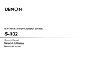
Graphical User Interface
Use this manual in combination with the
operating guide displayed on the GUI screen.
GUI Menu Operation (Eif'page 15)
GUI Menu Map ([§'page 16)
Language (GT'page 21)
VIDEO PROCESSOR
DVP-602CI
Owner's Manual
o SAFETY PRECAUTIONS
SAFETY INSTRUCTIONS
CAUTION:
TO REDUCE THE RISK OF ELECTRIC SHOCK, DO NOT REMOVE
COVER (OR BACK). NO USER-SERVICEABLE PARTS INSIDE.
REFER SERVICING TO QUALIFIED SERVICE PERSONNEL.
Iii
'
1
II
I
A
A
The lightning flash with arrowhead symbol, within an equilateral
triangle, is Intended to alert the user to the presence of
un Insulated "dangerous voltage" within the product's enclosure
that may be of sufficient magnilUde to constitute a risk of electric
shock to persons.
The exclamation pOint within an equilateral triangle IS Intended
to alert the user to the presence of Important operating
and maintenance (servicing) instructions in the literature
accompanying the appliance.
WARNING:
TO REDUCE THE RISK OF FIRE OR ELECTRIC SHOCK, DO NOT
EXPOSE THIS APPLIANCE TO RAIN OR MOISTURE.
CAUTION:
To completely disconnect this product from the mains, disconnect the plug
from the wall socket outlet.
The mains plug IS used to completely interrupt the power supply to the unit
and must be within easy access by the user.
VORSICHT:
Um d,eses Gerat vollstandlg von der Stromversorgung abzutrennen, zlehen
S,e b,tte den Stecker aus der Wandsteckdose
Der Netzstecker wlrd verwendet. um die Stromversorgung zum Gerat vbllig
zu unterbrechen; er muss fur den Benutzer gut und elnfach zu errelchen
seln
For European model
• DECLARATION OF CONFORMITY
We declare under our sole responsibility that this product, to which this
declaration relates, is in conformity with the following standards:
EN60065, EN55013, EN55020, EN61 000-3-2 and EN61000-3-3
FollOWing the prOVISions of 2006/95/EC and 2004/1 08/EC Directive
Read Instructions - All the safety and operating Instructions should be read
before the product IS operated.
Retain Instructions - The safety and operating instructions should be
2
retained for future reference
Heed Warnings - All warnings on the product and ,n the operating
3
Instructions should be adhered to.
Follow Instructions - All operating and use instructions should be
4
followed.
5 Cleaning - Unplug thiS product from the wall outlet before cleaning. Do not
use liquid cleaners or aerosol cleaners.
Attachments - Do not use attachments not recommended by the product
6
manufacturer as they may cause hazards
Water and Moisture - Do not use this product near water - for example,
near a bath tub, wash bowl, kitchen Sink, or laundry tub, ,n a wet basement;
or near a sWimming pool; and the like.
8. Accessones - Do not place thiS product on an unstable cart, stand. tripod,
bracket, or table. The product may fall, causing serious inlury to a child
or adult. and senous damage to the product. Use only with a cart, stand,
tnpod, bracket, or table recommended by the manufaclUrer, or sold With
the product. Any mounting of the product should
follow the manufacturer's instructions, and should
use a mounting accessory recommended by the
manufacturer
9 A product and cart combination should be moved
with care. Ouick stops, excessive force, and
uneven surfaces may cause the product and cart
combination to overturn
10 Ventilation - Slots and openings in the cabinet are provided for ventilation
and to ensure reliable operation of the product and to protect It from
overheating, and these openings must not be blocked or covered. The
openings should never be blocked by placing the product on a bed, sofa,
rug, or other similar surface. ThiS product should not be placed in a built-in
Installation such as a bookcase or rack unless proper ventilation IS proVided
or the manufaclUrer's inStructions have been adhered to.
11 Power Sources - ThiS product should be operated only from the type of
power source indicated on the marking label. If you are not sure of the type
of power supply to your home, consult your product dealer or local power
company For products Intended to operate from battery power, or other
sources, refer to the operating instructions.
12. Grounding or Polanzation - This product may be equipped With a polarized
alternating-current line plug (a plug having one blade wider than the other)
ThiS plug will fit into the power outlet only one way. This IS a safety feature.
If you are unable to insert the plug fully Into the outlet, try reversing the
plug. If the plug should still fail to fit. contact your electncian to replace your
obsolete outlet Do not defeat the safety purpose of the polarized plug.
DENON EUROPE
DiVision of D&M Germany GmbH
An der Landwehr 19, Nenetal,
0-41334 Germany
15
16
17.
18.
19
20.
21
22
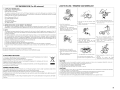
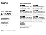
FIGURE A
EXAMPLE OF ANTENNA GROUNDING
AS PER NATIONAL
ELECTRICAL CODE
23
ANTENNA
• UBEREINSTIMMUNGSERKLARUNG
WIr erklaren unter unserer Verantwortung, dar., dleses Produkt. auf das
sich diese Erklarung bezieht, den folgenden Standards entsprrcht:
EN60065, EN55013, EN55020, EN61 000-3-2 und EN61 000-3-3
Entspllcht den Verordnungen der Dlrektlve 2006/95/EC und 2004/1 08/EC ,
13
DISCHARGE UNIT
INEC SECTION 810-20\
ELECTRIC
~~~~~~~NC:T--.I cr- I
GROUNDING CONDUCTORS
{NEC SECTION 810-2\)
_QQWER SERVICE GROUN[)I"<G
ELECTRODE SYSTEM
,NEC ART 250 PART HI
NEC - NATIONAL ELECTRICAL CODE
24
25.
Power-Cord Protection - Power-supply cords should be routed so that they
are not likely to be walked on or pinched by items placed upon or against
them, paying particular attention to cords at plugs, convenience receptacles,
and the pOint where they eXit from the product.
Outdoor Antenna Grounding - If an outSide antenna or cable system IS
connected to the product, be sure the antenna or cable system IS grounded
so as to provide some protection against voltage surges and built-up static
charges. Article 81 0 of the National Electllcal Code, ANSI/NFPA 70, prOVides
Information With regard to proper grounding of the mast and supporting
structure, grounding of the lead-In wire to an antenna discharge unit, size
of grounding conductors. location of antenna-discharge unit, connection to
grounding electrodes, and requirements for the grounding electrode. See
Figure A.
lightning - For added protection for thiS product during a lightning storm,
or when it IS left unattended and unused for long periods of time, unplug it
from the wall outlet and disconnect the antenna or cable system. ThiS will
prevent damage to the product due to lightning and power-line surges
Power Lines - An outSide antenna system should not be located in the
viCinity of overhead power lines or other electllc light or power CirCUitS, or
where it can fall into such power lines or CIrcuits. When Installing an outside
antenna system, extreme care should be taken to keep from touching such
power lines or cirCUits as contact with them might be fatal.
Overloading - Do not overload wall outlets, extension cords, or integral
convenience receptacles as this can result In a IIsk of fire or electllc shock.
Oblect and LiqUid Entry - Never push objects of any kind into thiS product
through openings as they may touch dangerous voltage points or short-out
parts that could result in a fire or electllc shock. Never spill liquid of any kind
on the product.
Servicing - Do not attempt to service this product yourself as opening or
removing covers may expose you to dangerous voltage or other hazards
Refer all servicing to qualified service personnel
Damage Requiring SerVice - Unplug this product from the wall outlet
and refer serVicing to qualified service personnel under the follOWing
conditions:
al When the power-supply cord or plug is damaged,
b) If liquid has been spilled, or objects have fallen into the product.
cl If the product has been exposed to rain or water,
dl If the product does not operate normally by following the operating
instructions. Adjust only those controls that are covered by the operatin9
instructions as an improper adjustment of other controls may result in
damage and Will often require extensive work by a qualified technician to
restore the product to its normal operation,
el If the product has been dropped or damaged In any way. and
fl When the product exhibits a distinct change in performance - this
,nd,cates a need for service
Replacement Parts - When replacement parts are required, be sure the
service technician has used replacement parts specified by the manufacturer
or have the same charactellstlcs as the original part. UnauthollZed
substitutions may result In fire, electllc shock, or other hazards
Safety Check - Upon completion of any service or repairs to this product,
ask the service technician to perform safety checks to determine that the
product IS in proper operating condition.
Wall or Ceiling Mounting - The product should be mounted to a wall or
ceiling only as recommended by the manufacturer
Heat - The product should be situated away from heat sources such as
radiators, heat registers, stoves, or other products (Including ampliflersl that
produce heat
o NOTE ON USE I
FCC INFORMATION (For US customers)
HINWEISE ZUM GEBRAUCH
1. COMPLIANCE INFORMATION
Product Name: VIDEO PROCESSOR
Model Number: DVP-602CI
This product complies with Part 15 of the FCC Rules. Operation is subject to the following two conditions: 11) this
product may not cause harmful interference, and (2) this product must accept any interference received, including
interference that may cause undesired operation.
Denon Electronics (USA). LLC
(a D & M Holdings Company)
100 Corporate Drive
Mahwah, NJ 07430-2041
Tel. (800) 497-8921
• Do not let foreign objects into the unit.
• Keep the unit free from moisture, water,
onr:l rhlst
• Avoid high temperatures.
2. IMPORTANT NOTICE: DO NOT MODIFY THIS PRODUCT
This product, when installed as indicated in the instructions contained in this manual, meets FCC requirements.
Modification not expressly approved by DENON may void your authority, granted by the FCC, to use the product.
Allow for sufficient heat dispersion when
installed in a rack.
• Vermeiden Sie hohe Temperaturen.
• Halten Sie das Gerat von Feuchtlgkelt.
Wasser und Staub fern
• Lassen Sis keine fremden Gegenstande in
das Gerat kammen.
f------------------1
f------------------1
Beachten Sis, dass eme ausreichende
Beluftung gewahrlelstet wird, wenn das
Gerat auf ein Regal gestellt wird
3. NOTE
This product has been tested and found to comply with the limits for a Class B digital device, pursuant to Part 15
of the FCC Rules. These limits are designed to provide reasonable protection against harmful interference in a
residential installation.
This product generates. uses and can radiate radio frequency energy and, if not installed and used in accordance
with the instructions, may cause harmful interference to radio communications. However. there is no guarantee
that interference will not occur in a particular installation. If this product does cause harmful interference to radio or
television reception, which can be determined by turning the product OFF and ON, the user is encouraged to try to
correct the interference by one or more of the following measures:
• Reorient or relocate the receiving antenna.
• Increase the separation between the equipment and receiver.
• Connect the product into an outlet on a circuit different from that to which the receiver is connected.
• Consult the local retailer authorized to distribute this type of product or an experienced radio/TV technician for
help.
This Class B digital apparatus complies with Canadian ICES-003.
Cet appareil numerique de la cia sse Best conforme a la norme NMB-003 du Canada.
• Unplug.the power cord when not using the
unit for long periods of time.
• Wenn das Gerat langere Zett nicht
verwendet werden soli, trennen Sie das
Netzkabel vom Netzstecker.
• Handle the power cord carefully.
Hold the plug when unplugging the cord.
• Gehen Sie vorslchtig mit dem Netzkabel
um.
Halten Sle das Kabel am Stecker, wenn Sle
den Stecker herausziehen.
*
(For apparatuses with ventilation holes)
A NOTE ABOUT RECYCLING:
This product's packaging materials are recyclable and can be reused. Please dispose of any materials
in accordance with the local recycling regulations.
When discarding the unit, comply with local rules or regulations.
Batteries should never be thrown away or incinerated but disposed of in accordance with the local
regulations concerning battery disposal.
This product and the supplied accessories, excluding the batteries, constitute the applicable product
according to the WEEE directive.
HINWEIS ZUM RECYCLING:
• Do not obstruct the ventilation holes.
• Decken Sie den Luftungsbereich nicht abo
-
Das Verpackungsmaterial dieses Produktes ist zum Recyceln geeignet und kann wieder verwendet werden. Bitte
entsorgen Sie aile Materialien entsprechend der brtlichen Recycling-Vorschriften
Beachten Sie bei der Entsorgung des Gerates die brtlichen Vorschriften und Bestimmungen.
Die Batterien durfen nicht in den Hausmull geworfen oder verbrannt werden; bitte entsorgen Sie die Batterien gemalS
der brtlichen Vorschriften.
Dieses Produkt und das im Lieferumfang enthaltene Zubehbr (mit Ausnahme der Batterien!) entsprechen der WEEEDirektive.
• Do not let insecticides, benzene, and
thinner come in contact with the unit.
• Lassen Sie das Gerat nicht mit Insektiziden,
Benzin oder Verdunnungsmitteln in
Beruhrung kommen.
• Never disassemble or modify the unit in
any way.
• Versuchen
Sie niemals das Gerat
auseinander zu nehmen oder zu verandern.
CAUTION:
•
•
•
•
•
The ventilation should not be impeded by covering the ventilation openings with items, such as newspapers, tablecloths, curtains, etc.
No naked flame sources, such as lighted candles, should be placed on the unit.
Observe and follow local regulations regarding battery disposal.
Do not expose the unit to dripping or splashing fluids.
Do not place objects filled with liquids, such as vases, on the unit
ACHTUNG:
• Die Beluftung sollte auf keinen Fall durch das Abdecken der Beluftungsbffnungen durch Gegenstande wie beispielsweise Zeitungen,
TlschtUcher, Vorhange o. A. behindert werden.
• Auf dem Gerat sollten keinerlei direkte Feuerquellen wie beispielsweise angezundete Kerzen aufgestellt werden.
• Bitte beach ten Sie bel der Entsorgung der Batterien die brtlich geltenden Umweltbestlmrnungen
• Das Gerat so lite keiner tropfenden oder spritzenden Flussigkeit ausgesetzt werden
• Auf dem Gerat sollten keine mit Flusslgkeit gefUliten Behalter wie beispielsweise Vasen aufgestellt werden.
II
I
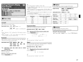
IGetting Started
Accessories·
Cautions on Handling
Cautions on Installation
About the Remote Control Unit·
Inserting the Batteries····
Operating Range of the Remote Control Unit
Part Names and Functions
Front Panel·
Display·················
Rear Panel
Remote Control Unit
,........
fJ
II
II
iii
RGB Range·
Vertical Stretch··
Auto Lip Sync
Monitor Out
Network Setup· .
Network Setup··
fJ Power Saving
II Network Information
Option Setup····
Source Delete
fJ GUI···
II Trigger Out
II Dimmer
iii Setup Lock
III Maintenance Mode
II Firmware Update
III Add New Feature··
Language
1
.
2
2
······2
····3
······3
······3
······4
······4
······5
······6
o
I
Preparations
. 7
Cables Used for Connections··
·····7
Video Conversion Function·······
·····8
Connecting Equipment with HDMI connectors
·····9
Connecting an HDMI-compatible player
·········9
Connecting an DVI-compatible player
.
10
Connecting Equipment with COMPONENT connectors
11
Connecting Equipment with VIDEO / S-VIDEO connectors
12
Connections to Other Devices····················
13
Network
······13
External Controller·
···14
Connecting the Power Cord··
··14
Once Connections are Completed
······14
1
I
GUI Menu Operations
Example ofthe Display ofthe GUI Mark at a Title·
Example of Display of Default Values·······
Examples of GUI Screen Displays·············
Example: Browse Menu (Top Menu)
Cursor Position Display
Operations
15
15
15
···15
. 15
. 15
GUI Menu M a p · · · · · · · · · · · ·
····16
1
.
.
Source Select
Input Source Selection
Settings Related to Playing Input Sources·
Video Setup················
.
fJ Optical·
.
II Rename·····
o
1
Parameter
Audio····
Audio Delay··
.
Picture Adjust···················
Contrast
fJ Brightness
.
II Chroma Level
liHue··················
iii DNR
.
III Enhancer
II Sharpness
o
17
········17
········17
. ···17
········17
········17
············18
······18, 19
············19
·······19
······19
...... ·19
····19, 20
···20
·20
··20
····20
··20
····21
·····21
.
o
-4
IConnections
1
IInformation
ISetup
HDMI Setup·
o Color Space
,"Contents
.
····21
·22
···22
Status·
HDMllnformation·
Signal Information
fJ Monitor 1
II Monitor 2
o
24
··24
·24
··24
24
.
IPlayback
Preparations··
. ..
.
Turning the Power On
.
Playing Video and Audio Equipment
Basic Operation
Operating the DVP·602CI Using a Browser
(Web control)··
.
24
·24
·24
24
.
.
IOther Operations and Functions
Personal Memory Plus Function
Last Function Memory··
Backup Memory··
Resetting the Microprocessor
Resetting the remote control unit
1
·····26
··26
······26
····26
·······26
Other Information········
ITroubleshooting·
.
.
···22
22
····23
·23
······23
······23
········23
····23
···23
··23
········23
·····23
ISpecifications
................................. ,
291
• Before turning the ON/STANDBY switch on
Check once again that all connections are correct and that there are
no problems with the connection cables.
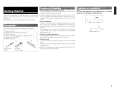
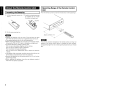
Getting Started
Thank you for purchasing this DENON product. To ensure proper
operation, please read these owner's manual carefully before using
the product.
After reading them, be sure to keep them for future reference.
Check that the following parts are supplied with the product.
CD Owner's manual
"........
..
(1) Warranty (for North America model only)
CIJ Service station list
@) Power cord (Cord length: Approx.
®
7-31/64 It 11.9 m)
Remote control IRC-1 093)
® R03/AAA batteries.................. .. "
@)
(For European
model)
~
(For North
America model)
~~~o
®
~~~~Q
~<~:J'.o
,,~
1
1
1
1
1
2
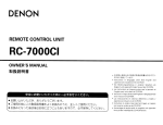
Note:
For proper heat dispersal, do not install this unit in a confined
space, such as a bookcase or similar enclosure.
• Power is supplied to some of the circuitry even when the unit is
set to the standby mode. When traveling or leaving home for long
periods of time, be sure to unplug the power cord from the power
outlet.
• About condensation
!f there is a major difference in temperature betvveen the inside of
the unit and the surroundings, condensation (dew) may form on
the operating parts inside the unit, causing the unit not to operate
properly
If this happens, let the unit sit for an hour or two with the power
turned off and wait until there is little difference in temperature
before using the unit.
• Cautions on using mobile phones
Using a mobile phone near this unit may result in noise. If so, move
the mobile phone away from this unit when it is in use.
I
* Note
'
i'-~- ~
~~" , ~, ~ ,,,,,,,.
~
,;,
",'
"""
Wall
'.
• Moving the unit
Turn off the power and unplug the power cord from the power
outlet.
Next, disconnect the connection cables to other system units before
moving the unit.
g ......
• Note that the illustrations in these instructions may differ from the
actual unit for explanation purposes.
2
I
About the Remote Control Unit
II Inserting the Batteries
G) Lift the clasp and remove the
rear lid.
Operating Range of the Remote Control
Unit
Point the remote control unit at the remote sensor when operating it.
(%) Load the two batteries properly
as indicated by the marks in
the battery compartment.
Q) Put the rear cover back on.
-N·n.
• Replace the batteries with new ones if the set does not operate
even when the remote control unit is operated close to the unit.
• The supplied batteries are only for verifying operation.
• When inserting the batteries, be sure to do so in the proper direction,
following the "$" and "8" marks in the battery compartment.
• To prevent damage or leakage of battery fluid:
• Do not use a new battery together with an old one.
• Do not use two different types of batteries.
• Do not attempt to charge dry batteries.
• Do not short-circuit, disassemble, heat or dispose of batteries in
flames.
• If the battery fluid should leak, carefully wipe the fluid off the inside
of the battery compartment and insert new batteries.
• Remove the batteries from the remote control unit if it will not be in
use for long periods.
• When replacing the batteries, have the new batteries ready and
insert them as quickly as possible.
3
Approx. 23 feet / 7 m
-N·n.
The set may function improperly or the remote control unit may not
operate if the remote control sensor is exposed to direct sunlight.
strong artificial light from an inverter type fluorescent lamp or infrared
light.
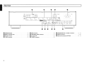
Part Names and Functions
I
For buttons not explained here, see the page indicated in parentheses ( ).
II Front Panel
IOENONI
..............
101 1
.....,1: \
~Gl
L ...~
SETUP
.
G~
./......:
.;8r..
RfTURN
":r'
-c~--s,
o Power operation button (ON/STANDBY)
•
Power indicator· .. ··
•
Remote control sensor ..... ---- .. -- .. --
....... (24)
..
.
..
(24)
......... (3)
o Display
o SETUP button ..
o Cursor buttons (.0, \7 <J l» ..
·(15)
8
8
ENTER button····
RETURN button
· .. (15)
·(15)
(15)
Display
f
f
.............. ..... ..... ..... ..... ..... ..... m111
o Information display
The input source name, setting values and other information are displayed here.
•
Monitor output indicators
These light according to the HDMI monitor output setting. When set to "Auto (Dual)", the indicators light
according to the connection status.
•
DIGITAL input indicator
This indicator lights up when OPTICAL input has been selected.
o HDMI indicator
This indicator lights up when HDMI signals are being input.
4
Rear Panel
I
.
~-f=
[J[]
•••••••••••••••••••••• ./iIlil. •••••••••••'
g~~II~t !~ ~
~
(ASSIGNABLE) .... \' ...... .? •••••••••
[J[]
I
'-'1------1·---1,----------1-\
i(~i
h~i~~:~:~~~~~:~~~~
: •••••••••••••••••••••••••••••••••••••••••••••••••••••••••••••
HDMI:O]
:._~ ~
0
~
GJ
0
m
rIl
~~~)--'::':~~)~~~ ~)·~~~~)7~~~~~~
~OmA MAX Ri~2~ET~OR~~~'
RS·232C
VIDEO
f2~EQ~~N]. ~IQ5Q •••••••••••••••••••••••••••••••••••[J[] ~
l JfI·_~_~ ~j~ls_TR_A1GH_TC_ABL_E~I_[J[]_IN_ J'..!.'!.~. .~. ~J .
--"""'T-------r----------------I- -1---1
o TRIGGER OUT jack
8
REMOTE CONTROL jacks
•
RS·232C connector
8
S-VIDEO connector
5
.
·(141
(141
·.. ·..
(14)
·(12)
o VIDEO connector ..
o COMPONENT VIDEO connectors
8
8
AC inlet (AC IN)
ETHERNET connector
(12)
.. ·(11)
..
(14)
(13)
o HDMI MONITOR OUT / OUTPUT connectors
(9 - 12)
4D> HDMIIN connectors
~ Digital audio connectors (OPTICAL)
(9, 101
..··
·(10 - 12)
I
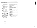
Control Unit
o Transmission indicator
~---~---..
I
, _• •wl
,
~oooooo)
I'
"'Alliirr',
f)----f-il:~(C?t;
i«)J.
- 1'······I
-
I
"Ai'-IiN'~
I
~ ~C?)~
r~)j
' -
i
lights···
(26)
f) Power off buttons (ALL OFF. OFF)
8
(24, 261
Advanced Setup button··
(26)
(» Direct source select buttons
(21)
o DNR button
.. (23)
o RESOLUTION buttons
f)
... (22)
Monitor select button (MONITOR SELl··· (17)
o DIMMER b u t t o n · · (20)
o Cursor buttons
1»
.
(.6. V<J
(15)
tD> SETUP button··
(15)
Q) Remote control signal transmitter··
~ Power on buttons (ALL ON, ON)·
(3)
.... (24, 26)
~ Progressive mode button
(PROGRESSIVE)
.... (22)
4D Source select buttons (SOURCE)
t9 ASPECT button
(19, 21)
(22)
~ STATUS button·
lB ENTER button··
tEl RETURN button··
(24)
(15)
.
(15)
·u·u-
The TUNER SELECT, REMOTE 10, RDS, PTY, RT, A
- G and MEMORY buttons cannot be used.
6
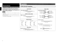
Preparations
,
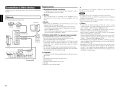
Connections
Connections for all compatible audio and video signal formats
are described in this owner's manual. Please select the types of
connections suited for the equipment you are connecting.
With some types of connections, certain settings must be made
on the OVP-602CI. For details, refer to the instructions for the
respective connection items below.
I ·U·U.
• Do not plug in the power cord until all connections have been
completed.
• When making connections, also refer to the operating instructions of
the other components.
• Do not bundle power cords together with connection cables. Doing
so can result in humming or noise.
II Cables Used for Connections
Select the cables according to the equipment being connected.
Audio cables
Video cables
Optical digital connections
[2j
Component video connections
(J
G
(Green)~ ~
[£]
(Blue) ~
Optical cable
(Red)
Audio and video cables
(Greenl
0
~~
~O(Y)
'tiJl....J- O(PB/CB)
l
~~(PR/CR)
Component video cable
HOMI connections
§)O
9J
®
~.
1
J
(Blue) ®~
§)
(Red) ®!~
19-pin HDMI cable
®(y)
r
®!IPB/CB)
l
....."., @(PR/CR)
BNC (75 O/ohms) cable
t
Audio signal:
o",p",
Input
t
Signal direction
f
Video signal:
'"~,
Output
o",p",
f
S-Video connections
0
'"~,
Input
Output
[J::J
c::[]
0
::[]JP
0
S-Video cable
Video connections
(Yellow)
0
eQO::
75 O/ohms pin-plug video cable
Other cable
H:iiiH
Network connections (wired LAN)
D mD
Ci@)
Ethernet cable
7
D
~
DVI-D HDMI cable
I§I
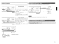
Video Conversion Function
• This function automatically converts various formats of video signals input to the DVP-6D2CI into the
format used to output the video signals from the DVP-6D2CI to a monitor.
• The DVP-6D2Cl's video input/output circuitry is compatible with the following four types of video
signals:
Digital video signals: HDMI
Analog video signals: Component video, S-Video and Video
I
[Flow of video signals inside the DVP-602CI]
High picture
quality playback
J1
J1
=-=--'11
1
0-
I~
r--=--'I...
(§J
HDMI connector
v
P,IC' PRlC,
000
Component video
/1
l>
C§J
HDMI connector
/ ' /
Monitor
connectors
·0
C
S-Video connector
o
Video connector
Video inputs
Video outputs
The resolution for the HDMI device connected to the monitor output terminal of the DVP-6D2CI can be
checked by selecting "Information" - "HDMI Information" - "Monitor 1" and "Monitor 2" on the GUI
menu (r2!T'page 24).
-u·na
• When a non-standard video signal from a game machine or some other source is input, the video
conversion function might not operate.
• Video conversion of 1DSDp component video input signals is not possible.
8
I
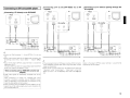
Connecting Equipment with HOMI
connectors
With HDMI connections, the video and audio signals can be transferred
with a single cable.
Connectin
OConnecting a TV to the DVP-602CI via an AV
amplifier
Plaver
[iJ
HOMI
HOMI
OUT
IN
HOMI
OUT
~
~
oConnecting aTV directly to the DVP-602CI
PlaYer
~
TV
~~
~~
OUT
IN
~
~
~
~I 1Il
'~[.jj.
'-----------/~
i.~
m
m
L-------I----'-'====-~d
~
AV amplifier
~
Copyright protection system (HDCP)
In order to play the digital video and audio signals of a DVD- Video or
DVD-Audio disc using HDMI/DVI connections, both the connected
DVD player and monitor must be equipped for a copyright protection
system called "HDCP" (High-bandwidth Digital Content Protection).
HDCP is a copy protection technology consisting of data encoding
and mutual identification of the devices.
The DVP-602CI is HDCP-compatible. For details on the DVD player or
monitor you are using, refer to its operating instructions.
* The DVP-602CI is supported to the feature of HDMllisted below.
• 30 and 36 bit Deep Color
• x.v.Color
• Auto Lip Sync Correction
*: "x.v.Color" is trademark of Sony Corporation
*
• Use a CPPM-compatible DVO player to play OVO-Audio discs that
are copyright-protected by CPPM.
• The audio signals output from the HOM I connector (sampling
frequency, bit rate, etc.) may be restricted by the connected device.
• Video signals are not output properly when using devices that are
not HOCP-compatible.
• Video signals are not output if the input video signals do not match
the monitor's resolution. In this case, switch the DVD player's
resolution to a resolution with which the monitor is compatible.
• Use a cable on which the HOMI logo is indicated (a certified HDMI
product) for connection to the HOMI connector. Normal playback
may not be possible when using a cable other than one on which the
HDMIIogo is indicated (a non-HOM I-certified product).
• If the monitor or OVD player does not support deep color, deep color
signal transfer is not possible .
• If the monitor or DVD player does not support x.v.Color, x.v.Color
signal transfer is not possible.
• If the monitor does not support" Auto Lip Sync Correction" function,
this function will not work.
The DVP-602CI can transmit the following sound formats.
Compatible audio
format
The DVP-602CI does not support the HDMI control (CEC) function.
When using the HDMI control function with a device other than
the DVP-602CI, connect an HDMI control-compatible device to the
MONITOR 1 terminal.
9
Details
Discs
(examples)
2-channel linear PCM
2ch 32-192 kHz
16/20/24 bits
CD, DVD-Video,
DVD-Audio
Multi-channel linear
PCM
8ch 32-192 kHz
16/20/24 bits
DVD-Audio
Dolby Digital, DTS
Bitstream
DVD-Video
DSD
2/5.1 ch
2.8224 MHz
1 bit
SACD
Dolby Digital Plus,
Dolby TrueHD,
DTS-HD
Bitstream
HD DVD,
Blu-ray Disc
Audio playback is not possible with the DVP-602CI.
There can be no sound output from the HDMI terminal when the
"Resolution" under "Source Select" - "Video Setup" on the DVP602CI GUI menu is set to 480p/576p, VGA, SVGA. XGA (@"page 22)
Use a Deep Color compatible cable for connection to Deep Color
compatible devices.
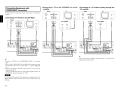
Connecting an DVI-compatible player
oConnecting a TV directly to the DVP-602CI
r
Player
oConnecting a TV to the DVP-602CI via an AV
amplifier
Player
-AUDIO-
TV
OPTICAL
OUT
-AUDIO OPTICAL
OUT
DVI-D
OUT
DVI-D
OUT
HDMI
IN
AV amplifier
IT ~
HOMI
IN
HOMI
OUT
oConnecting to a TV without passing through the
AV amplifier
l~O
TV
Player
-AUDIO-
OPTICAL
OUT
DVI-D
i, ~,~~
[OJ
HDMI~
• Connect an HDMI connector 2 - 6 and OPTICAL 2 in the same
way.
• When using an optical cable for the digital audio connection, make
the settings at GUI menu "Source Select" - "Optical" (l2ff'page
22)
• Output to the player's OPTICAL output terminal in a sound format
supported by the TV.
If the TV's HDMI input does not support Dolby Digital and DTS, set
the OPTICAL output of the player to "PCM".
When connecting with an HDMI/DVI converter cable
(adapter)
B
1
~
l
OPTICAL
IN
W
I!J
~
~
[g-ill
I CD
ill
.
@@@ §~
':I~~I
[!]
€!'iI
Sl'WiHIl'M..!
i
-AUDIO -
~
mB
O
AV amplifier
~
s,t I·ij~-
HDMI
IN
OUT
_TOll®
~
'"
@
i, ~,~~ I'"
:i.t ~
!I!I~!!I,~
W
~
d
I
g--
I
W
I!J
~
lE5J
ill
le;J
I!J
~
@@@ §~=
':1~11
I (II 31_lOAm£;;;;J ""
IICOV_ _ _ lCIltDlJ11
IE IiJI
~l'M.1
@
!I!I~!!I,~
,
• If the connected monitor or DVD player only has a DVI-D connector,
use an HDMI/DVI converter cable. When using a DVI cable, no audio
signals are transmitted.
• There can be no sound output from the HDMI terminal when the
"Resolution" under "Source Select" - "Video Setup" on the DVP602CI GUI menu is set to 480p/576p, VGA, SVGA, XGA (l2ff'page
22)
Output to the player's OPTICAL output terminal in a sound format
supported by the AVamplifier_
• HDMI video signals are theoretically compatible with the DVI
format.
When connecting to a monitor, etc., equipped with a DVI-D
connector, connection is possible using an HDMI/DVI converter
cable, but depending on the combination of components in some
cases the video signals will not be output.
• When connecting using an HDMI/DVI converter adapter, the video
signals may not be output properly due to poor connections with
the connected cable, etc.
10
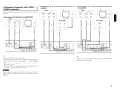
oConnecting a TV to the DVP-602CI via an AV
amplifier
Connecting Equipment with
COMPONENT connectors
Player
Carefully check the inputs and outputs, and be sure to interconnect
correctly.
-AUDIO-
--VIDEO--
OPTICAL
OUT
COMPONENT VIDEO
PA
-AUDIO OPTICAL
OUT
Q;J
l
Y
GGG
oConnecting a TV directly to the DVP-602CI
Player
OUT
Po
TV
--VIDEO-COMPONENT VIDEO
oUT
PA
Ps
Y
~~
AV amplifier
HDMI
IN
GGG
HDMI
IN
HDMI
OUT
C§J
C§J
oConnecting to a TV without passing through the
AV amplifier
TV
Player
-
AUDIO-
OPTICAL
OUT
COMPONENT VIDEO
OUT
PR
BI
0
--VIDEO--
PH
Y
GGG
Im
AV amplifier
-AUDIO OPTICAL
IN
BI
HDMI
IN
C§J
~
't::=~~---
,
• Connect an OPTICAL 2 and COMPONENT VIDEO 2 in the same
way.
• When using an optical cable for the digital audio connection, make
the settings at GUI menu "Source Select" - "Optical" ((B"'page
22)
• Output to the player's OPTICAL output terminal in a sound format
supported by the TV.
If the TV's HDMI input does not support Dolby Digital and DTS, set
the OPTICAL output of the player to "PCM" .
•
~[.U.
Do not connect the output of the component connected to the DVp·
602CI's OPTICAL output connector to any input connector other than
OPTICAL.
11
Output to the player's OPTICAL output terminal in a sound format
supported by the AVamplifier.
Connecting Equipment with VIDEO I SVIDEO connectors
Carefully check the inputs and outputs, and be sure to interconnect
correctly.
oConnecting a TV to the DVP-602CI via an AV
amplifier
Player
-AUDIOOPTICAL
OUT
[£]
oConnecting aTV directly to the DVP-602CI
Player
TV
0
--VIDEO--
-AUDIO OPTICAL
OUT
SVIDEO
OUT
VIDEO
OUT
0
B
G
-i
......".,.-
a,~
~l
m
~
(j)
r~
le5l
3
eEl
~
~
~
T~'T''l ':1
,
I
C!J
(!31
--
=
I CD
s-.CoI&f
W
l
G
HDMI
IN
HDMI
OUT
I§J
I§J
~~
~
=== === ===I=~~=lr======
[
'"
<-~I;--
jU ~O~I:
IAi
[!]
•
~
SVIDEO
OUT
OPTICAL
OUT
VIOEO
OUT
0
[£]
HOMI
IN
~
I§J
AV amplifier
I!l
-AUDIOOPTICAL
IN
[£]
I
~~m
~
Cd I
~
--VIDEO--
-AUDIO-
or
I§J
Ig~
ill
0
VIDEO
OUT
IN
'-'
0
SVIDEO
OUT
AV amplifier
I 1l
TV
Player
--VIDEO--
HOMI
or
oConnecting to a TV without passing through the
AVamplifier
Plt,Co
• Connect an OPTICAL 2 in the same way.
• When using an optical cable for the digital audio connection, make
the settings at GUI menu "Source Select" - "Optical" (Gf'page
22)
• Output to the player's OPTICAL output terminal in a sound format
supported by the TV.
If the TV's HOM I input does not support DolbyDigital and DTS, set
the OPTICAL output of the player to "PCM".
....
-.
,...,----
.....-
---
a~, ~
~
11l
rn
G:
L-----C=:...-:,;:[E;J=-.I~
------Hr:,. m
51
te;;;
I
(j)
l<=
'--'
~
.
l[g~1
~j
(j)
~
0
~
-,
ill
~
~Im
,- -, . -
l~l; ~
<=0
~~
lOITOIffi
-
c€I
li:II
~r~-
i,,*I':'I~O~I,~
(!J
~
,
l'M:t,.".
,
Output to the player's OPTICAL output terminal in a sound format
supported by the AVamplifier.
-u·n.
Do not connect the output of the component connected to the DVP602CI's OPTICAL output connector to any input connector other than
OPTICAL
12
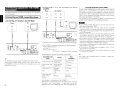
I
Reguired system
Connections to Other Devices
Carefully check the inputs and outputs, and be sure to interconnect
correctly:
o
Broadband Internet connection
A broadband line connection to the Internet is required in order to
use the DVP-602CI's firmware update.
o Modem
This is a device that is connected to the broadband line to
communicate with the Internet. Some are integrated with the
router.
Network
For firmware update and web control.
Computer
D
II
OID
ToWANside
C
Router
I.
To LAN port
To LAN port
• When using the DVP-602CI, we recommend you use a router
equipped with the following functions:
. Built-in DHCP (Dynamic Host Configuration Protocol) server
This function automatically assigns IP addresses on the LAN.
Built-in 1OOBASE-TX switch
When connecting multiple devices, we recommend a switching
hub with a speed of 100 Mbps or greater
~ o Ethernet cable (CAT-5 or greater recommended)
CL;]I-----~[0]
D
D
o Router
LAN port /
Ethernet
connector
• The DVP-602CI does not come with an Ethernet cable.
• Some flat type Ethernet cables are easily affected by noise.
We recommend using a normal type cable.
• If the sound is broken in an environment in which there is much
power supply noise from electric products or in a noisy network
environment, use a shielded type Ethernet cable (For America
Canada model).
• For the Ethernet cable, used a shielded twisted pair (STP) cable.
Do not use an unshielded twisted pair (UTP) cable, as it may exceed
noise standard limits (For European model).
o Computer
A computer with the following specifications is required to use a
web control:
-as
Windows® XP Service Pack2; Windows Vista
• Internet browser
Microsoft Internet Explorer 5.01 or later
• LAN port
- 300 MB or more free disk space
13
For connections to the Internet. contact an ISP (Internet Service
Provider) or a computer shop.
'~[.jj.
• A contract with an ISP is required to connect to the Internet.
No additional contract is needed if you already have a broadband
connection to the Internet.
• The types of routers that can be used depend on the ISP. Contact an
ISP or a computer shop for details.
o
Others
• If you have an Internet provider contract for a line on which
network settings are made manually, make the settings at GUI
menu "Setup" - "Network Setup" (@"page 18, 191.
• With the DVP-602CI, it is possible to use the DHCP and Auto IP
functions to make the network settings automatically.
• When using a broadband router (DHCP function), the DVP-602CI
sets the IP address, etc, automatically.
When using the DVP-602CI connected to a network with no DHCP
function, make the settings for the IP address, etc., at GUI menu
"Setup" - "Network Setup" (@"page 18, 19).
• The DVP-602CI is not compatible with PPPoE. A PPPoE-compatible
router is required if you have a contract for a line of the type with
which the PPPoE is set.
• Depending on the ISP with which you have your contract, it may
be necessary to make proxy server settings to use the Network
function. If you made proxy server settings on the computer to
connect to the Internet. make the proxy server settings on the
DVP-602CI in the same way.
Connecting ,the Power Cord
II External Controller
Wait until all connections have been completed before connecting the power cord.
~
~
IfJI~
lID
(j)
(j)
Ie;J
Ie;J
~
I ill
_nJl®
~·B
Ic§1fi~
'"
RS-232C connector
This connector is used for an external controller.
III
."_@@'"@ ~
~I~~I
"'~ !I!I~!!I,~~~ *
[!]
EliI
UfW".iIICt«t:
I
To household
power outlet
Power cord
(included)
CD
CV
®
If you wish to control the DVP-602CI from
an external controller using the RS-232C
connector, perform the operation below
beforehand.
Turn on the DVP-602CI's power.
Turn off the DVP-602CI's power from the
external controller.
Check that the DVP-602CI is in the standby
mode.
I
~
North America model
AC 120 V, 60 Hz
I~C)
European models
AC 230 V, 50 Hz
-N,h.
Insert the AC plugs securely. Incomplete connections could cause noise.
~
~
(j)
(j)
(E9J
Ie;J
®
Ie;J
IfJI ~oo [c§1fi~
'"
I CDIe;J-mIe;J
ifl~:-~I ~ lil~I.~~I,~~~
00
i!lI
UIWiMl1;Okl
[5]
~
,
~
J!JI/QI
,
I
AUX
OUT
Input
Output
~~~
I't.Q
IO,Qo
Trigger output jack
The power of an external device equipped with
a trigger input jack can be turned on and off in
association with operations on the DVP-602CI.
For details, see GUI menu "Setup" - "Option
Setup" - "Trigger Out" (l(W'page 20).
• Output level: 250 mA / 12 V
Check the trigger input conditions of the
connected device.
II Turning the Power On
(l(W'page 24)
Extension jack for future use.
Infrared
retransmitter
14
I
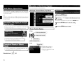
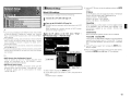
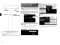
Examples of GUI Screen Displays
Some typical examples are described below.
GUI Menu Operations
Example: Browse Menu (Top Menu)
With the DVP-602CI, settings and operations for most functions can
be performed by operating while looking at the GUI menus displayed
on the monitor screen.
Operations
The same operation is possible on the main unit or remote control
Unit.
1
2
*
3
4
When an x.v.Color signal or a 1080p component video signal and
computer resolution (ex. VGA) have been input, the GUI screen cannot
be superimposed.
Press the SETUP button.
The GUI menu is displayed.
Press the J0,. V
or operated.
l> button to select the menu to be set
To return to the previous item, press the <l or
Example of the Display of the GUI
Mark at a Title
Items for which this mark is indicated at the title can be
operated from the GUI.
We recommend performing such operations from the GUI.
HDMI Setup
Make settings for HDMI video/audio
output.
~
~
l=::J
This is the GUI icon for this setting item or for the
menu series to which this item belongs.
Example of Display of Default
Values
In lists of selectable items or adjustable ranges, the item
surrounded by a border is the default value.
[Selectable items]
15
~
OFF
II Cursor Position Display
o
Icon
~
Switch the selected item
.,
1
Switch to the next item I
'-------------
~
Selected item
o
List
Video Setup
* Switch the selected item using
the 6. \1 button.
RETURN button.
Press the ENTER button to enter the setting.
Press the SETUP button to finish.
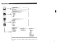
,GUI Menu.Map
.
INFORMATION (oaT'page 24)
•••••
o Status
o HDMI Information
I
SOURCE SELECT (iEF'page 21, 22)
~~
~
.
o HOMI 1 -
6, COMPo 112, S-VIDEO, VIDEO
• Video Setup
· i/p Scaler
· Resolution
· Progressive Mode
· Aspect
• Optical
• Rename
PARAMETER (oaT'page 23)
•
•••••••••
••
•
•••
•
••••••••
o Audio Delay
o Picture Adjust
• Contrast
• Brightness
• Chroma level
• Hue
·DNR
• Enhancer
• Sharpness
SETUP (!:':rpage 17 - 21)
o HDMI Setup IGT'page 17)
•
•
•
•
•
Color Space
RGB Range
Vertical Stretch
Auto lip Sync
Monitor Out
o Network Setup I@"page 18, 19)
• Network Setup
• Power Saving
• Network Information
o Option Setup I@"page 19 -
21)
• Source Delete
• GUI
· Screensaver
· Wall Paper
· Format
· Text
• Trigger Out
• Dimmer
• Setup lock
• Maintenance Mode
• Firmware Update
• Add New Feature
o language (@"page 21)
When "Screensaver" is set to "ON", the screensaver is activated if no operation is performed for about
3 minutes.
16
~
~!
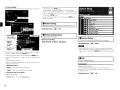
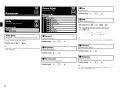
Setup
fJRGB Range
II Monitor Out
Make settings for RGB output range.
Make settings for HDMI monitor output.
[Selectable items] I Normal
I Enhanced
I Auto (Dual) I Monitor 1 Monitor 2
~ Operating from the remote control unit
Make detail settings for various parameters.
-When "YCbCr" is selected under "Color Space", "RGB Range" will
have no effect.
- The computer resolution output will be "Enhanced" irrespective of
this setting.
I
[Selectable items]
Press the MONITOR SEL button.
r--
Auto (Dual I
~-
Monitor 1
----~
Monitor 2 ....
II Vertical Stretch
The image is displayed in full-screen.
Color Space
[Selectable items]
ON
~
RGB Range
Vertical Stretch
Auto Lip Sync
Monitor Out
o Color Space
DAuto Lip Sync
Automatic compensation for timing shift in audio and video
output.
[Selectable items]
~
OFF
Make settings for output color space.
[Selectable items]
I YCbCr I RGB
#
When connected to a monitor with a DVI-D connector (HDCP
compatible) using an HDMI/DVI converter cable, the signals are output
in RGB format. regardless of this setting.
17
Auto Lip Sync only works when connected to a TV which supports
HDMI Lip Sync.
-When "Monitor Out" is set to "Auto (Dual)", connections with
the MONITOR 1 or MONITOR 2 connectors are recognized
automatically.
-If both the MONITOR 1 and 2 connectors are connected and
"Resolution" is set to "Auto", the signals are output with a resolution
compatible with both monitors.
-If "Resolution" is set to something other than "Auto", check the
resolutions with which your monitor is compatible at GUI menu
"Information" - "HDMI Information" - "Monitor 1" and "Monitor
2" and set accordingly (idT'page 24).
-When "Monitor Out" is set to "Auto (Dual)", and a not supported
sound format is input to Monitor 1 and Monitor 2, the sound is not
output from both terminals.
- The "Auto (Dual)" function may not operate normally depending
on the device connected to the monitor output terminal. Under the
circumstances, set either" Monitor 1" or "Monitor 2".
II
0
Network Setup
®
IP Address
Wired LAN settings
Set the IP address within the ranges shown below. The Network
function cannot be used if other IP addresses are set.
CLASS A: 10.0.0.0 - 10.255.255.255
CLASS B 172.16.0.0 - 172.31.255.255
CLASS C: 192.168.0.0 - 192.168255.255
Use this procedure to configure the Wired LAN settings.
1
Power Saving
Network Information
• If you are using a broadband router (DHCP function), there is no need
to make the settings at "Setting the IP Address" and "Setting the
Proxy", since the DHCP function is set to "ON" in the DVP-602CI's
default settings.
• If the DVP-602C1 is being used connected to a network without the
DHCP function, the network settings must be made. In this case,
some knowledge of networks is required. For details, consult a
network administrator.
• If you cannot connect to the Internet, recheck the connections and
settings (iGFpage 13).
• If you do not understand about Internet connection, contact your ISP
(Internet Service Provider) or the store from which you purchased
your computer.
2
3
Use the f::, VI> button to input the address and press the ENTER
button.
Connect the LAN cable (o:::w'page 13).
Subnet Mask
Turn on the DVP-602CI (o:::w'page 24).
DVP-602CI performs automatic network setup due to the DHCP
function.
When connecting to a network that has no DHCP function,
perform the setting in Operation 3.
When connecting an xDSL modem or terminal adapter directly
to the DVP-602CI, input the subnet mask indicated in the
documentation supplied by your provider. Normally input
255.255.255.0.
Set the IP address at the GUI menu "Setup" "Network Setup" - "Network Setup".
When connected to a gateway (router), input its IP address.
Default Gateway
Primary DNS
Secondary DNS
If there is only one DNS address indicated in the documentation
supplied by your provider, input it at "Primary DNS". If there are
two or more DNS addresses, input the first one at "Secondary
DNS".
®
Use the V button to select "Exit" and press the ENTER button.
Setup is complete .
'* When connecting to the network via a Proxy server, select" Proxy"
and press the ENTER button (@"page 19 "Proxy settings").
CD
• DHCP (Dynamic Host Configuration Protocol) :
These are systems by which the IP address and other network
settings are automatically set for the DVP-602CI, computer,
broadband router and network devices.
• DNS (Domain Name System) :
This is a system for converting the domain names used when
browsing Internet sites (for example, .. www.denon.jp .. ) into the
IP addresses actually used for communications (for example,
"202.221.192.106").
I CV
CD
CV
Set "OFF".]
Select" Detail" and press the ENTER button
Use the <11> button to set "DHCP" to "OFF", then press the V
button.
The DHCP function is disabled.
18
I
o Proxy settings
®
Use the 6. V [> button to input the proxy server address or domain
name and press the ENTER button.
When "Address" is selected in Operation ®: Input the address
When "Name" is selected in Operation ®: Input the domain name
®
Use the 6. V <l [> button to input the proxy server port number
and press the ENTER button.
Make this setting when connecting to the Internet via a proxy server.
(J) Use the V button to select "Exit" and press the ENTER button.
Setup is complete.
GUI
I
fJ Power Saving
Trigger Out
Make setting for power saving when not connected to network.
[Selectable items]
~
Dimmer
Setup Lock
OFF
Maintenance Mode
Firmware Update
Add New Feature
®
®
®
Selecting the
input method
Example) Address
Input the
address
or domain
name.
II Network Information
o Source Delete
Display network information.
[Items to be checked]
DHCP= ON or OFF
IP Address
Remove input sources that are not used from the display.
MAC Address
[Selectable items]
~
Delete
.~[.jj.
Input the port
number.
CD
On the GUI menu, select "Setup" - "Network Setup" - "Network
Setup" - "Detail" and press the ENTER button.
CD
®
Use the 6. V button to set "Proxy" and press the ENTER button.
Use the <l [> button to set "Proxy" to "ON" and press the V
button.
The proxy server is enabled.
• Input sources being used in the various zones cannot be deleted.
• Input sources set to "Delete" cannot be selected from GUI menu
"Source Select" or using the SOURCE button on the remote control
unit.
fJGUI
Make GUI related settings.
@ Use the <l [> button to select the proxy server input method, and
then press the V button.
[Selectable items]
Address : Select when inputting by address.
Name
: Select when inputting by domain name.
[Characters that can be input]
A-Z
a-z
0-9
! #%& '( )*+, - .f:; <=" >?@[\](space)
19
Screensaver
Make screensaver settings.
Use the screensaver to prevent burn-in on the monitor screen.
When set to "ON", the screensaver is activated if there is no activity
for about 3 minutes.
[Selectable items]
~
OFF
Wall Paper
Change the GUI background.
[Selectable items]
I Picture I
Black
Gray
Blue
Format
II Trigger Out
II Maintenance Mode
Select the conditions to turn on the trigger out with respect to the
input source, HDMI monitor, etc.
For details about the trigger out function, see page 14.
This sets the function for maintenance by a DENON serviceperson
or installer. (For professional use only.)
[Selectable items]
This function allows a DENON serviceperson or installer to check the
DVP-602CI's status and make settings via the Internet.
ON
-N'O»
Select the video output signal format to match the monitor.
[Selectable items]
Setting with Respect to the Input Source
I NTSC I PAL
I PAL I NTSC
-Noi»
(for North America model)
When the input source set to on is selected, the trigger out turns on.
(for European model)
Setting with Respect to the Monitor
When the HDMI monitor set to on is selected, the trigger out turns
on.
When a format other than the video format of the connected monitor
is set, the picture will not be displayed properly. Use the procedure
described below to change the video format.
~ Operating from the main unit
* The GUI menu is not displayed when performing this setting.
CD
®
®
Press and hold the ENTER and RETURN buttons for at least 3
seconds.
"Video Format" appears on the display.
Use the <J [> button to make the setting.
Press the ENTER, SETUP or RETURN button to complete the
setting.
DDimmer
Update the firmware of the receiver.
You can check for firmware updates. You can also check approximately
how long it will take to complete an update.
Adjust display brightness of the receiver.
[Selectable items] I Bright I Dim
Dark
OFF
~ Operating from the remote control unit
Press the DIMMER button.
Bright
-
Dim ~
Dark
-----l
:+:1.) ideo FO"-·f'!.::I"t:
",-,1
rnL
Start
Execute the update process.
When updating starts, the power indicator becomes red and the GUI
screen is shut down. The amount of update time which has elapsed
is displayed.
When updating is complete the power indicator becomes green and
normal status is resumed.
* If the display reads as shown below, check the settings and network
environment, then update again.
Display
Text
Text information display.
~ OFF
I
II Firmware Update
Check for Update
OFF _
[Selectable items]
Only use this function if so instructed by a DENON serviceperson or
installer.
Description
mSetup Lock
Updating failed
Updating failed.
Protect settings from inadvertent change.
Login failed
Failure to log into server.
[Selectable items]
ON
~
Server is busy
Server is busy. Wait a while then try again.
Connection fail
Failure connecting to server.
• When "Setup Lock" is set to "ON", the settings listed below can
no longer be changed. Also, "SETUP LOCKED!" is displayed if you
attempt to operate related buttons.
· GUI menu operations
Resolution
· Progressive Mode
· Aspect
DNR
· Status
• To cancel the setting, press the SETUP button to re-display the
"Setup Lock" screen, then change the setting to "OFF".
20
I
~
II Add New Feature
Display the new functions (payment required) which can be
purchased for downloading to the DVP-602CI and upgrade.
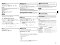
Source Select
When you purchase a new function and register your user information,
"Registered" is displayed on this menu and you can proceed with the
upgrade.
Upgrade
Execute the upgrade process.
When updating starts, the power indicator becomes red and the GUI
screen is shut down. The amount of update time which has elapsed
is displayed.
When updating is complete the power indicator becomes green and
normal status is resumed.
lil
Use this procedure to select the input source and make the settings
related to playing input sources.
[Selectable items]
English
Fran'rais
(for North America model)
English
Deutsch
Fran'rais
Nederlands
Svenska
8:i$:i!
Italiano
Espanol
(for European model)
* If the upgrade is not successful, an error message identical to those
in "Firmware Update" will appear on the display, check the settings
and network environment. then update again.
Notes concerning use of "Firmware Update" and
"Add New Feature"
• In order to use these functions, you must have the correct system
requirements and settings for a broadband Internet connection .
• Do not turn off the power until updating/upgrading is completed.
• Even with a broadband connection to the Internet. approximately
1 hour is required for the updating/upgrading procedure to be
completed.
Once updating/upgrading starts, normal operations on the
DVP-602CI cannot be performed until updating/upgrading is
completed.
Furthermore, updating/upgrading the firmware may reset the
backup data for the parameters, etc., set for the DVP-602C1.
Information regarding the "Firmware Update" function and "Add New
Feature" will be announced on the DENON web site each time related
plans are defined.
~ Operating from the main unit or remote
control unit
[Operation on the main unit]
Press the Do \J button.
[Operation on the remote control unit]
Press the Direct source select or SOURCE button.
The desired input source can be selected directly.
o
SOURCE
21
fJOptical
This can be set when "i/p Scaler" is set to "ON".
o To enjoy 1080p/24 Hz video images, use a monitor which supports
1080p/24 Hz video signals.
o With film source (24 Hz), you can enjoy a film-like image. It is
recommended that you use 1080p/60 Hz for video source and mixed
source.
o It is not possible to convert a 50 Hz signal to 1080p/24 Hz. It is output
at a resolution of 1080p/50 Hz.
o It IS not possible to convert a 1080p/60 Hz signal to 1080p/24 Hz.
o
Resolution
VGA
SVGA
XGA
WXGA
WXGA2
SXGA
o Video Setup
Setting the video source.
i/p Scaler
Select digital input connector to assign to this source.
[Input source]
[Selectable items]
I HDMll - 611 COMPONENTl /2[
I S-VIDEO II VIDEO]
OPTICAL 1 /2
None
I
Pixel number configuration
640 x 480
800 x 600
1024 x 768
1280 x 768
1360 x 768
1280 x 1024
Make settings for i/p scaler function
[Selectable items]
ON
~
~ (HDMI
OFF
Progressive Mode
1 _ 6)
(CONP 1 /2 S-VIDEO,VIDEO)
When "i/p Scalar" is "ON", the Deep Color (12 bit) signal is converted
to 10 bit.
o When "i/p Scalar" is "ON", the i/p Scalar has no effect on the
x.v.Color signal or computer resolution input.
o
Select optimum progressive mode for video material.
II Rename
[Selectable items] I Auto I Videol
Change the display name for this source.
Names containing up to 8 characters can be input.
Video2
~ Operating from the remote control unit
Press the PROGRESSIVE button.
[Characters that can be input]
A-Z a-z 0-9 !#%&'()*+,-./:;<=">?@[\)(space)
I
_._ _.-J
AUTO ----- VIDEO 1
'--------- VIDE02
Resolution
Make settings for resolution of HDMI video output signal (a25'page 27
"Resolution input/output conversion table")
This can be set when "i/p Scaler" is set to "ON"
[Selectable items] I Auto I 480p1576p
Aspect
l080p
10BOi
1080p/24
VGA
WXGA WXGA2
SXGA
720p
SVGA
XGA
~ Operating from the main unit or remote
control unit
[Operation on the main unit]
Press the
<l
[> button.
This sets the aspect ratio when outputting 480i/576i or 480p/576p
input signals from the HDMI output connector.
[Selectable items] ~ Normal
~ Operating from the remote control unit
Press the ASPECT button.
Full
- - - - Normal
[Operation on the remote control unit)
Press the RESOLUTION button.
This can be set when "i/p Scaler" is set to "ON'.'
22
~
Parameter
liHue
Adjust color hue.
(llilJ
[Variable range]
-6
-
[TI -
+6
Low
Middle
Picture Adjust
•
Contrast
IJDNR
Brightness
Reduce overall picture noise.
Chroma Level
[Selectable items] ~
Hue
High
DNR
~ Operating from the remote control unit
Enhancer
Press the
DNR button.
Sharpness
OFF
High
Audio Delay
DContrast
Compensate for mismatched timing between video and audio.
Adjust picture contrast.
This sets the delay time for audio signals.
[Variable range]
~ - 200 ms
[Variable range]
-6
-
[TI -
-
Low ~
Middle
---J
This function is not effective when the input signal is 1080p (60/50Hz).
+6
mEnhancer
The adjustment range is 0 to 100 ms when the Auto Lip Sync Correction
function is activated.
If) Brightness
Emphasize picture contours.
Adjust picture brightness.
[Variable range]
[Variable range]
[TI -
[TI -
fJ Sharpness
II Chroma Level
Adjust picture definition.
Adjust picture chroma level (saturation).
[Variable range]
[Variable range]
-6
+12
+12
-
[TI -
+6
,
-6
-
[TI -
+6
The "Picture Adjust" setting is not effective when "i/p Scalar" is "OFF"
and at the time of 480i/576i output.
23
~
~l
Information
[~-~c=J
Playback
Turning the Power On
<ON/STANDBY>
I
Press the <ON/STANDBY> or [POWER ON] button.
The power indicator flashes green and the power turns on.
[Items to be checked]
Select Source
i/p Scaler
Name
Input Mode
[POWER OFF]
~ f:'~
I:Q
I
I
Resolution
I
I
L .
~
I
Turning the Power Off
[POWER ONI
I
'
i
Press the <ON/STANDBY> or [POWER OFF] button.
The power is set to the standby mode.
.~t.)i.
Power continues to be supplied to some of the circuitry even when the
power is in the standby mode. When leaving home for long periods
of time or when traveling, unplug the power cord from the power
outlet.
I
,
G-+-[SOURCE
~,
SElECn
Signal Information
Monitor 1
Monitor 2
Basic Operation
1
o Signal Information
The HOMI input/output signal information is displayed.
[Items to be checked]
Resolution
Color Space
Pixel Depth
About the button names in these explanations
: Buttons on the main unit
[ 1 : Buttons on the remote control unit
Button name only:
Buttons on the main unit and remote control unit
<
fJMonitor 1
The HOM I monitor 1 information is displayed.
II Monitor 2
G)Load the OVO, CO or other software in the player
(!Gf'See the operating instructions of the respective devices.)
®To playa video device, switch the monitor input.
(!Gf'See the monitor's operating instructions.)
2
(
The HOMI monitor 2 information
[Items to be checked]
>
IS
Interface
displayed.
Supported Resolution
You can also check the status of the OVP-602CI by pressing the
STATUS button on the remote control unit.
Prepare the equipment.
3
Use the [SOURCE SHEen button to select the input
source.
~:
"Source Select" l!Gf'page 21, 221
)
Start playback.
(!Gf'See the operating instructions of the respective devices.)
24
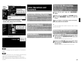
~ Operating
the D\lP..602£1 Using a
Browser fWeb control)
I~
<ON/STA-N-D-BV->-----<-S-£~r=J 1
'l"tlis flJnctionlets you operate tna DVfN302CI using Internet
~J~~ orer.
<RETURN>
I
[ALL OFF]
1 I~
6
L-----!.._
Switch "OFF" the "Power Saving" setting under
"Setup" - "Network Setup" on the GUI menu
(lGf"page 19).
the DVP-602CI's
address with "Setup"
2 -Check
"Network Setup" - "Network Information" on the
IP
GUI menu (lI:Tpage 19).
[ALL ONI
[ADVANCED SETUP]
4
When the top menu is displayed, click on the menu
you want to operate.
Click when you
operate the setup
menu (~Example: 2)
Click when you
operate each
zone
(~Example: 1)
Click when you
operate a small screen
such as a PDA screen,
etc. (~Example: 3)
5
Operate.
[Example:1] Main Control Screen
Click when you
update to the latest
information (
*)
Click".J" and select
from the displayed
items
3
Enter the DVP-602CI IP address in Internet Explorer's
address box.
For example, if the IP address of DVP-602CI is
"192.168.000.003", enter ''http://192.168.0.3''.
About the button names in these explanations
> . Buttons on the main unit
[ J : Buttons on the remote control unit
Button name only:
Buttons on the main unit and remote control unit
<
25
Click to add a setting to the "Favorites"
in your browser
*:Normally, there is a change to the latest information each time
you operate. When operated from the main unit, click because the
screen is not updated.
Click the menu from which you want to make
settings
1
2
The display on the right becomes each setting screen
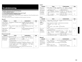
I
Click "SAVE" when you want to save setting::J'
and click "LOAD" when you want to call settings
Becomes each operation screen
3
Turn off the power using the <ON/STANDBY>
button.
While pressing the <SETUP> and <RETURN> buttons,
press the <ON/STANDBY> button for at least one
second.
Once the display starts flashing at intervals of about 1
second, release the two buttons.
._----
If in step 3 the display does not flash at intervals of about 1 second,
start over from step 1.
[Example:3] PDA menu screen
1
Hold down the [All OFF] button on the remote control
unit and press the [ADVANCED SETUP] button with
the tip of a pen.
The Transmission Indicator light blinks four times.
2
Hold down the [All ON] button on the remote control
unit and press the [ADVANCED SETUP] button with
the tip of a pen.
The Transmission Indicator (DVP) light blinks four times.
_~rIJj.
You cannot change setup menu operations on the PDA menu
screen.
-¢rIU·
· To perform web control, you must connect a web control device
such as a PC to the same network as the DVP-602CI.
· With web control. some network settings, etc., cannot be set.
· When updating firmware, settings made by the web controller may
be reset.
26
I
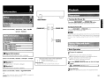
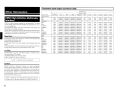
II Resolution input/output conversion table
MONITOR OUT
Other Information
Resolution Setup
Input Formats
480p/576p
nop
1080i
1080p
1080p/24
VGA
SVGA
XGA
WXGA
WXGA2
SXGA
VIDEO/S-VIDEO
HDMI (High-Definition Multimedia
Interface)
HDMI is a digital interface standard for next generation TVs based
on DVI (Digital Visual Interface) standards and optimized for use in
consumer equipment.
Non-compressed digital video and multi-channel audio signals are
transmitted with a single connection.
HDMI is also compatible with HDCP (High-bandwidth Digital Contents
Protection), a technology for protecting copyrights that encrypts digital
video signals in the same was as with DVI.
Deep Color
Eliminates on-screen color banding, for smooth tonal transitions and
subtle gradations between colors.
Enables increased contrast ratio.
Can represent many times more shades of gray between black and
white.
At 30-bit pixel depth, a four times improvement would be the minimum,
and the typical improvement would be eight times or more.
x.v.Color
Next-generation "x.v.Color" color space supports 1.8 times as many
colors as existing HDTV signals.
Lets HDTVs display colors more accurately.
Enables displays with natural, vivid colors.
"x.v.Color" is trademark of Sony Corporation.
Lip Sync
Because consumer electronics devices are using increasingly
complex digital signal processing to enhance the clarity and detail of
the content, synchronization of video and audio in user devices has
become a greater challenge and could potentially require complex enduser adjustments. HDMI 1.3 incorporates an automatic video/audio
synching capability that allows devices to perform this synchronization
automatically with total accuracy.
"HDMI", "HDMllogo" and "High-Definition Multimedia Interface"
are trademarks or registered trademarks of HDMI Licensing LLC.
27
480i
480p
nOp/60Hz
1080i/60Hz
1080p/60Hz 1080p/24Hz
VGA
SVGA
XGA
WXGA
WXGA2
SXGA
576i
576p
nOp/50Hz
1080i/50Hz
1080p/50Hz 1080p/50Hz
VGA
SVGA
XGA
WXGA
WXGA2
SXGA
480i
480p
nOp/60Hz
1080i/60Hz
1080p/60Hz 1080p/24Hz
VGA
SVGA
XGA
WXGA
WXGA2
SXGA
480p
480p
nOp/60Hz
1080i/60Hz
1080p/60Hz 1080p/24Hz
VGA
SVGA
XGA
WXGA
WXGA2
SXGA
nOp/60Hz
480p
nOp/60Hz
1080i/60Hz
1080p/60Hz 1080p/24Hz
VGA
SVGA
XGA
WXGA
WXGA2
SXGA
1080i/60Hz
480p
nOp/60Hz
1080i/60Hz
1080p/60Hz 1080p/24Hz
VGA
SVGA
XGA
WXGA
WXGA2
SXGA
Component
576i
576p
nOp/50Hz
1080i/50Hz
1080p/50Hz 1080p/50Hz
VGA
SVGA
XGA
WXGA
WXGA2
SXGA
576p
576p
nOp/50Hz
1080i/50Hz
1080p/50Hz 1080p/50Hz
VGA
SVGA
XGA
WXGA
WXGA2
SXGA
nOp/50Hz
576p
nOp/50Hz
1080i/50Hz
1080p/50Hz 1080p/50Hz
VGA
SVGA
XGA
WXGA
WXGA2
SXGA
1080i/50Hz
576p
nOp/50Hz
1080i/50Hz
1080p/50Hz 1080p/50Hz
VGA
SVGA
XGA
WXGA
WXGA2
SXGA
HDMI
480i
480p
nOp/60Hz
1080i/60Hz
1080p/60Hz 1080p/24Hz
VGA
SVGA
XGA
WXGA
WXGA2
SXGA
480p
480p
nOp/60Hz
1080i/60Hz
1080p/60Hz 1080p/24Hz
VGA
SVGA
XGA
WXGA
WXGA2
SXGA
nOp/60Hz
480p
nOp/60Hz
1080i/60Hz
1080p/60Hz 1080p/24Hz
VGA
SVGA
XGA
WXGA
WXGA2
SXGA
1080i/60Hz
480p
nOp/60Hz
1080i/60Hz
1080p/60Hz 1080p/24Hz
VGA
SVGA
XGA
WXGA
WXGA2
SXGA
1080p/60Hz
480p
nOp/60Hz
1080i/60Hz
1080p/60Hz 1080p/60Hz
VGA
SVGA
XGA
WXGA
WXGA2
SXGA
1080p/24Hz
480p
nOp/60Hz
1080i/60Hz
1080p/60Hz 1080p/24Hz
VGA
SVGA
XGA
WXGA
WXGA2
SXGA
576i
576p
nOp/50Hz
1080i/50Hz
1080p/50Hz 1080p/50Hz
VGA
SVGA
XGA
WXGA
WXGA2
SXGA
576p
576p
nOp/50Hz
1080i/50Hz
1080p/50Hz 1080p/50Hz
VGA
SVGA
XGA
WXGA
WXGA2
SXGA
nOp/50Hz
576p
nOp/50Hz
1080i/50Hz
1080p/50Hz 1080p/50Hz
VGA
SVGA
XGA
WXGA
WXGA2
SXGA
10801/50Hz
576p
nOp/50Hz
1080i/50Hz
1080p/50Hz 1080p/50Hz
VGA
SVGA
XGA
WXGA
WXGA2
SXGA
1080p/50Hz
576p
nOp/50Hz
1080i/50Hz
1080p/50Hz 1080p/50Hz
VGA
SVGA
XGA
WXGA
WXGA2
SXGA
[Audio)
Symptom
I
No sound is
output from
the monitor or
AVamplifier
connected
with HDMI
connections.
Troubleshooting
If a problem should arise, first check the following:
1. Are the connections correct?
2. Is the set being operated as described in the owner's manual?
3. Are the other components operating properly?
If this unit does not operate properly, check the items listed in the table below. Should the problem persist.
there may be a malfunction.
In this case, disconnect the power immediately and contact your store of purchase.
Symptom
Cause
Countermeasure
Page
Power does not
• Connection of the power cord is • Check that the power plugs are
turn on, or turns
faulty.
securely inserted into the DVPoff directly after it
602CI's AC inlet and the wall
power outlet.
was turned on.
14
Display is off.
• The "Dirnmer" setting is set to • Set to something other than
"OFF".
"OFF".
20
Power turns off
suddenly and
power indicator
flashes red.
• Set is damaged.
• Turn off the power and contact a
DENON service center.
-
Symptom
Cause
Countermeasure
Page
• Replace with new batteries.
• Operate within the specified
range.
• Remove the obstacle.
3
3
• Insert the batteries in the
proper direction, following the
polarity marks in the battery
compartment.
• Reset the remote control unit.
3
26
-
22, 27
22
Cause
Countermeasure
Page
• The format of the GUI and TV • Match the format of the GUI and
(NTSC or PAL) do not match.
TV
No picture
appears.
• The connections between the • Check the connections.
DVP-602CI and monitor are
faulty.
·The monitor's input setting is • Set properly.
wrong.
9 - 12
• The connections to the HDMI • Check the connections.
connectors are faulty.
• The monitor is not compatible • Connect a monitor that is
with
copyright
protection
compatible
with
copyright
(HDCP)
protection (HDCP).
• The HDMI format of the player • Match the HDMI format of the
player and monitor.
and monitor do not match.
9 - 12
No picture
appears
with HDMI
connections.
20
-
9
-
[Network)
Symptom
3
Page
The on-screen
display does not
appear.
[Remote Control Unit)
Set does not work • Batteries are worn.
properly when
• You are operating outside of the
remote control
specified range.
unit operated.
• Obstacle between main unit and
remote control unit.
• The batteries are not inserted in
the proper direction, as indicated
by the polarity marks in the
battery compartment.
• The remote control unit is not set
for use with the DVP-602CI.
Countermeasure
[Video)
Symptom
[General)
Cause
·The player's OPTICAL output • Set the player's OPTICAL
is not set to a sound format output to a sound format (PCM)
supported by the TV.
supported by the TV.
• The DVP-602CI's "Resolution" • Change the "Resolution" to a
is set to 480p/576p, VGA, SVGA,
setting other than 480p/576p,
VGA, SVGA, XGA
XGA
DVP-602CI's
"Optical" • Match the "Optical" setting to
·The
the input terminal.
setting is wrong.
Server is not
found, or it is
not possible to
connect to the
server.
Cause
Countermeasure
Page
·The computer's or router's
firewall is activated.
• Computer's power is not turned
on.
• Server is not running.
• Set's IP address is wrong.
• Check the computer's or router's
firewall settings.
• Turn on the power.
-
• Launch the server.
• Check the set's IP address.
19
-
28
,
Specifications
o General
Power supply:
Power consumption:
Maximum external dimensions:
Weight:
AC 120 V. 60 Hz
North America model:
AC 230 V. 50 Hz
European model:
North America model'
90W
90W
European model:
03 W (Standby)
434 (W) x 107 (H) x 280 (0) mm (17-3/32" x 4-7/32" x 11-1{32)
4.2 kg (9 Ibs 4 oz)
o Remote control unit (RC-1093)
Batteries:
Maximum external dimensions:
Weight:
R03/AAA Type (two batteries)
49(W) x 220 (H) x 24.5 (0) mm (1-59/64" x 8-21/32" x 31/32)
114 g (Approx 4 oz) (including batteries)
* For purposes of improvement. specifications and design are subject to change without notice.
I
29
DENON
www.denon.com
Denon Brand Company, D&M Holdings Inc.
Printed in Japan OOD 511 4750005
DENON SERVICE NETWORK I n~~~~
•
•
•
•
•
•
•
•
Please consult the outlet where the equipment was purchased.
Bitte wenden Sie sich an den Handler. bei dem Sie das Produkt gekauft haben.
SVP veuillez consulter votre revendeur.
Neemt u alstublieft contact op met het verkooppuntwaar u de apparatuur heeft gekochto
Por favor consulte en el establecimiento donde compr6 el equipo.
Vanligen ta kontakt med butiken dar du kopt utrustningen.
Rivolgetevi al rivenditore che vi ha venduto I'apparecchio.
Contacte a loja onde comprou 0 equipamento.
• i.rPJffjt• .A;;t;;IIiY-Jilnta~ 0
• ~lcJf~UiJf~~*fJliY-Jjflj1T!hfij 0
Australia
Audio Products Group Pty Ltd. 67 O'Riordan Street Alexandria NSW 2015, PO Box 150, Mascot NSW 1460 Australia
Tel: 1300 134400 Fax: +61 295780159
Austria
Digital-Professional-Audio Vertriebsges.m.b.H., Seebbckgasse 59, A-1160 Wien Tel: 01-480-1006 Fax: 01-485-7679
Transtel-Sabima PVBA Duboisstraat 48, B-2060 Antwerpen, Belgium Tel: 03-237-3607
Belgium
Canada
D&M CANADA INC. 5-505 Apple Creek Blvd., Markham, Ontario, L3R 5Bl Tel: 905-475-4085 Fax: 905-475-4159
China
et! ir~~iruloJ'B'! ~ (...ttm )fl"[lN0 P] ...ttmmiltmrjJ~887.f%iJ<~:*:1I601 O~
et!i'/i:(021 )64372299 f~~:(021 )64339973 iEBi.Iii: 200020 7:::Jt:&p~IHHM~: 021-62949285
Czech republic
EUROSTAR OSTRAVA sr.o. areal Vodni stavby Praha, budova A2 Dobronicka 635,14800 Praha 4 Czech Rep.
Tel: 261-112-901 Fax: 261-112-904
Hifi Klubben A/S Dali Aile 1, 9610 Noerager, Denmark Tel: 45-96 72 1000 Fax: 45-96 72 10 14
Denmark
Finland
Soundata Oy Hameentie 157 5th floor 00560 Helsinki Finland Tel: +358-(0)9-47693300 Fax: +358-(0)9-47693310
DENON FRANCE A division of D&M France SAS Tour Ventose, 2 rue des Bourets, 92156 Suresnes Cedex, France
France
Tel:+33(0)1-41-383230 Fax: +33(0)1-41-380110
DENON DEUTSCHLAND A division of D&M Germany GmbH An der Landwehr 19, D-41334 Nettetal, Germany
Germany
Tel: +49(0)2157-1208-0 Fax: +49(0)2157-1208-15
Greece
KINOTECHNIKI LTD. 14, PYRGOU STR 16675, GLYFADA ATHENS Tel: +302109601071 Fax +302109601072
Hong Kong
D&M Sales and Marketing (H.K.) Ltd. Unit 501, Ocean Centre, Harbour City, 5 Canton Road, Tsimshatsui, Kowloon, Hong Kong
Tel: 852-2516-5864 Fax: 852-2516-5940
W¥tE1L~~i:JIull.~~I'HH5Wctm¥tEJiittm1'FrjJ{,'5fl!501~ mil~: 852-2516-5864 f$Jj;: 852-2516-5940
Hungary
A.IDA Audio Kft. 1112 Budapest Olt u. 37. Hungary Tel: 01-248-2030 Fax: 01-248-2039
Einar Farestveit & co hf., Borgartun 28, P.Box 5440, 125 Reykjavik. Tel: +3545207900 Fax: +3545207910
Iceland
India
PROFX SERVICE CENTRE Advanced Audio Solutions (Bangalore)Pvt. Ltd.
No 53, K.H.Road, Opp .Big Bazaar, Bangalore - 560 027, India Tel: 080 3297 0853 Fax: 080 2211 2043
Indonesia
PT Autoaccindo Jaya. Cideng Barat NO.7 Jakarta, Indonesia Tel: +62-21-633-2730 Fax: +62-21-632-2886
Israel
Newpan Ltd. 14 Rosansky st. Rishon Lezion 75706, Israel. Tel: +972-3-953-5900 Fax: +972-3-961-6193
Audiodelta S.r.1.19 Via Pietro Calvi 20129 Milano Italy Tel: 39-02-5411-6008/39-02-5412-8253 Fax: 39-02-5412-0258
Italy
D&M Sales and Marketing Korea Ltd. Chung Jin B/D., 10F, 53-5, Wonhyoro 3 Ga, Yongsan-Gu, Seoul, 140-719, Korea
Korea
Tel: 02-715-9041 Fax: 02-715-9040
Malaysia
Wo Kee Hong Trading Sdn Bhd. 2nd Floor, (Left Wing), Bangunan Infinite Centre, Lot 1, Jalan 13/6, 46200 Petaling Jaya,
Selangor Darul Ehsan, Malaysia Tel: 03-7954-8088 Fax: 03-7954-7088
Mexico
Labrador, SA de CV Callejon del Naranjo 35, Naucalpan, 53560, Edo. Mex., Mexico Tel: 52-5359-5161 Fax: 52-5357-1775
Netherlands
Penhold BV Poppenbouwing 58, NL-4191 NZ Geldermalsen, Netherland Tel: 31-345-588 080 Fax: 31-345-588085
New Zealand
Avalon-Pacific Marketing Limited. 15C Vestey Drive, Mt Wellington, Auckland, New Zealand.
PO Box 11 631 Ellerslie, Auckland, New Zealand Tel: +64-9-573-5933 Fax: +64-9-573-3720
Norway
Hi-Fi Klubben Marcus Thranes gate 4-6, 0473 Oslo, Norway Tel: +47228063 10 Fax: +47 22 80 63 29
Lotteworld Audio Video Systems Incorporated CET Building Mezzannine Floor NO.4 Mindanao Avenue, Barangay
Philippines
Bahay Toro, Project 8, Quezon City, Philippines. Tel: +632-929-5334 Fax: +632-929-1343
Poland
HORN DISTRIBUTION SA Ulica Kurantow 34,02-873 Warszawa Poland Tel: +4822331 5533 Fax: +4822331 5500
Portugal
Videoacustica Qta. Do Paizinho-Armazem 5-Estrada De Circunvalai;ao-Apart. 3127 1303 Lisboa Codex
Tel: +351214241770 Fax: +351214188093
ALL (E&E) Service Center Pte Ltd. Machtech Industrial Building, #06-04, No.2, Kallang Pudding Road, Singapore 349307
Singapore
Tel: 6747-8274 Fax: 6748-9007
Slovakia
BIS AUDIO s.r.o. Dobronivska cesta 1642/696001 Zvolen Tel:045-5400 703 Fax:045-5400 704
South Africa
Mandarin Distributors SA 10 Thora Crescent, Wynberg Ext.3 Sandton, PO. Box 5137, Johannesburg Republic of South
Africa Tel: 27-11-444-8445 Fax: 27-11-444-8363
Spain
Gaplasa SAAV. Ing. Conde de Torroja, 25, 28022 Madrid Tel: 91-746-00-45 Fax: 91-329-44-57
Sweden
Hi-Fi Klubben Gbteborg Skiinegatan 25, 41252 Gbteborg Tel:031 3351010 Fax:031 3351019
Switzerland
DKB household AG, Abteilung Elektronik. Eggbuhlstrasse 28, CH-8052 Zurich, Switzerland
Tel: 01-306-1626 Fax: 01-306-1690
Taiwan RoO.C.
D&M Sales and Marketing Taiwan Ltd. 6F-2 N0148, Songjiang Rd., Taipei City 10458, Taiwan R.O.C.
Tel: 02-2522-1308 Fax: 02-2100-1175
Mahajak Development Co., Ltd. 46 Mahajak Building, Sukhumvit Soi 3 (Nana-Nua) Klongtoey, Wattana, Bangkok
Thailand
Thailand. 10110 Tel: 66-2-256-0020 Fax: 66-2-253-1696
Turkey
Ertekin electronik tic. ve san. a.s. Galipdede Caddesi No.: 113 Kuledibi-Karakby / Istanbul, Turkey
Tel: +90(212)293-9515 Fax: +90(212)249-3512
U,A.E.
VV & SONS L.L.C. Street No-ll/B, Road NO-128, Shed No-39 AI Khabisi, Deira, Dubai, UAE
Tel: +971-4-266-2435, 268-4575 Fax: +971-4-266-2052
Ukraine
Mirs Ltd. Osipova str. 37/0ffice 1, 65012 Odessa, Ukraine
Tel: +380 (482)305530 Fax: +380 (482)305555
DENON UK A division of D&M Audiovisual Ltd. Moorbridge House, Padbury Oaks, 579 Bath Road,
United
Kingdom & Eire
Longford, Middlesex, UB7 OEH, United Kingdom Tel: +44(0)1753-680568 Fax: +44(0)1753-689697
U.S.A,
DENON ELECTRONICS (USA), LLC (a D&M Holdings Company)
100 Corporate Drive, Mahwah, NJ 07430-2041 Tel: 800-497-8921 Fax: 888-544-8434
Vietnam
Anh Duy Manufacturing - Trading Co., Ltd. 170 Ung Van Kheim St., Ward 25, Blinh Thanh Dist., HCMC, Vietnam
Tel: +8488983424 Fax: +8488983425
•
•
•
•
•
•
•
•
If there is no service center in your local area, please contact one of our overseas service centers, listed above, for follow-up service consultation.
1st kein Service-Center in Ihrer Nahe, setzen Sie sich bitte miteinem der hier aufgelisteten Adressen in Verbindung.
Si il n'y a pas destation technique proche de chez vous, veuillez contacter nos I' un de noscentres techniques, listes ci dessous, pour toutes demandes techniques.
Ais er geen servicecenter bij uin de buurt is, neem dan contact op een een van onze bovengenoemdeservicecenters voor ondersteuning.
Si no hay un servicio tecnico en su zona, por favor contacte con uno de los servicios tecnicos centrales, indicados abajo, para realizar un seguimiento de su consult.
Om det inte finns nagon auktoriserad Denon-verkstad dar du bor, kontakta en av vara internationella servicecentra (se ovan).
Se non ci sono dei centri assistenza autorizzati nella vostra zona, potete fare riferimento agli altri centri assistenza autorizzati, vedi elenco sopra, per qualsiasi
consultazione tecnica.
Caso nao exista um centro de assistE'lncia tecnica na sua area, consulte um dos centros acima apresentados
• PO'6il1t1!J:Mzl!\\muJ}cj:J{", ~j1J~.t.*pIT9U:$:0E'j#ll9~ijlil:mcj:J,e.,1!t~1:!H&mU9nl':§:
• '6 !!3tt!l7Cijlil~cj:J,e., iwJl**.t.j£FMU'lXinie~ilfijj.JJE1~cj:J ,e., ):J ~~N!IJj(ijE1~'l1ii~)
0
0
0
0
DENON
www.denon.com
Denon Brand Company, D&M Holdings Inc.
Printed in Japan ODD 515 0921 908 iii 709
DENON~
LIMITED WARRANTY
(USA / CANADA)
USA (ENGLISH)
CANADA (ENGLISH)
CANADA (FRENCH)
PAGE
2
3
4
USA
DENON ELECTRONICS (USA), LLC
(a D&M Holdings Company)
100 Corporate Drive
Mahwah, NJ 07430-2041
(800) 497-8921
(888) 544-8434 Fax
DENON REGIONAL SUPER SERVICE CENTERS (Repair only-No parts orders please)
PYRAMID AUDIO
UNITED RADIO SERVICE
AUDIO SERVICES
305 E. Braker Lane
Austin, TX 78753-2746
(512) 458-8292
(512) 453-4542 Fax
5717 Enterprise Parkway
E. Syracuse, NY 13057-2905
(800) 634-8606
(315) 446-8505 Fax
544 Central Dr., Suite 101
Virginia Beach, VA 23454-5245
(757) 498-8277
(757) 498-9554 Fax
INNER SOUND
NORMAN'S ELECTRONICS
GOLD CROWN ELECTRONICS
1416 S.E. Morrison Street
Portland, OR 97214-2646
(503) 238-1955
(503) 238-1787 Fax
3653 Clairmont Road
Atlanta, GA 30341-4907
(770) 451-5057
(770) 455-8337 Fax
Victoria Business Park
129 E. SavaronaWay
Carson, CA 90746-1406
(310) 538-8282
(310) 538-8281 Fax
SERVICE WIDE TECHNOLOGIES
ELECTRONICE EXPRESS
2239 Curtiss Street
Downers Grove, IL 60515-4010
(630) 969-7333
(630) 969-7330 Fax
1809 E. Fabyan Parkway
West Chicago, IL 60185
(630) 208-4600
(630) 208-4601 Fax
CANADA
D&M CANADA INC.
5-505 Apple Creek Boulevard
Markham Ontario, L3R 5B1
(905) 475-4085
(905) 475-4159 Fax
WARRANTY (HOME)
OOD 515 0944 707
1
i
DEN 0 N
m
.,"~"
w;ll be
h",,,"
"I", ili, U.S.A
®
l
,
~
:
:
:
:
:
:
:
:
:
:
:
LIMITED WARRANTY
Length of Non-Transferable Warranty
This warranty on your DENON product which is distributed and warranted by DENON ELECTRONICS (USA), LLC remains in effect for the following periods from
the date of the original consumer purchase from an AUTHORIZED DENON ELECTRONICS (USA), LLC DEALER.
~~
:
:
t
,:_._.
•
~
,
~
,
~
•
~
:
•
"
i_'.
~,:
:
,
~
,
~
'_.
=
t
What is Covered
Except as specified below, this Warranty covers all defects in material and workmanship in this product occurring during the above warranty periods. The following are
not covered by the Warranty: (I) Any product which is not distributed in the U.S.A. by DENON ELECTRONICS (USA), LLC. (2) Any product which is not purchased
in the U.S.A. from an authorized DENON dealer, unless the product is purchased through the U.S.A. Military Exchange Service where the Warranty will be One (I)
year for all products listed above except in the case of Cartridges, Accessories, Remote Controller and Headphone which will remain at 90 days. (Note: AUTHORIZED
DENON DEALERS can be identified by DENON AUTHORIZED DEALER sticker displayed in the stores. If you are uncertain as to whether a dealer is a DENON
AUTHORIZED DEALER, please contact DENON as listed below). (3) Any product on which the serial number has been defaced, modified or removed. (4) Damaged
deterioration or'malfunction resulting from: a) Accident, act of nature, abuse, misuse, neglect, unauthorized product repair, opening of or modification or failure to follow
instructions supplied with the product. b) Repair or attempted repair by anyone not authorized by DENON. c) Any shipment of the product (claim must be presented to
carrier). (5) Items subject to wear from normal usage (tape heads. canridges, stylus, battery, etc.). (6) Periodic check-ups which do not disclose any defect. (7) Use of the
product outside the U.S.A. (8) Damaged magnetic tape or CDIDVD discs. (9) Use in industrial, commercial, andlor professional applications. (10) Any installation or
removal charges resulting from product failure.
If
i
t
i
f
t
i
t
t
t
t
t
ff
,
I
,
,
:
•
~_._.
t
t_:_'
What We Will Pay For
If during the applicable warranty period from the date of original consumer purchase your DENON product is found to be defective by DENON, DENON will
repair, or at its option, replace with new, used or equivalent model, such defective product without charge for parts or labor.
f
How to Obtain Warranty Performance
If your unit ever needs service, it may be taken or shipped to any authorized DENON service station or DENON ELECTRONICS (if you are uncertain as to
whether a service station is DENON authorized, please contact DENON as listed below.) In all other cases, the following procedures apply whenever your unit must
be transported for warranty service;
,
I
,
,
a. You are responsible for transporting your unit or arranging for its transportation.
b. If shipment of your unit is required;
You must pay the initial shipping charges, but we will pay the return shipping charges if the repairs are covered by the Warranty.
c. WHEN RETURNING YOUR UNIT FOR WARRANTY SERVICE, A COPY OF THE ORIGINAL SALES SLIP MUST BE ATTACHED.
d. You should include the following: your name, address, daytime telephone number, model and serial number of the product and a description of the problem.
In the case of a CD or DVD Player, please enclose ONE (I) disc that the unit has failed with for test reasons. It will be returned with the unit.
1.::__'.
,=,_.
~_._.
.
t
~_.
t
THIS WARRANTY IS VALID IN THE U.S.A. ONLY.
.
:
THIS WARRANTY IS EXPRESSLY MADE IN LIEU OF ALL OTHER WARRANTIES, EXPRESSED OR IMPLIED, INCLUDING WITHOUT LIMITATION,
WARRANTIES OF MERCHANTABILITY AND FITNESS FOR A PARTICULAR PURPOSE.
,
,
OUR LIABILITY IS LIMITED TO THE REPAIR OR REPLACEMENT, AT OUR OPTION, OF ANY DEFECTIVE PRODUCT AND SHALL IN NO EVENT
INCLUDE INCIDENTAL OR CONSEQUENTIAL COMMERCIAL OR PROPERTY DAMAGES OF ANY KIND. WE ARE NOT RESPONSIBLE FOR
PRODUCTS LOST, STOLEN AND/OR DAMAGED DURING SHIPPING.
t
;
~
SOME STATES DO NOT ALLOW LIMITATIONS ON HOW LONG AN IMPLIED WARRANTY LASTS AND/OR DO NOT ALLOW THE EXCLUSION OF
INCIDENTAL OR CONSEQUENTIAL DAMAGES, SO THE ABOVE LIMITATIONS AND EXCLUSIONS MAY NOT APPLY TO YOU.
i
t.
This warranty gives you specific legal rights, but you may also have other rights which vary from state to state. This Warranty may not be altered other than in a
writing signtd by an officer of Denon Electronics USA, LLC.
..::,.
.,
:
:
:
:
DENON ELECTRONICS (USA), LLC
(a D&M Holdings Company)
100 Corporate Drive
Mahwah, NJ 07430-2041
~
t
~1l111'
2
,Pod os a trademark of Apple Inc.. reg'stered ,n the U.S. and other count"es.
i
1111.
~"llIh'''''-'IH'''''''''IIII''''''''IIII'''''''IIII''''''-'IIII'''''''''"'''''''.11I'· ....·.lllh,. . .·.tlll··. . .·.11Il'·.... ·,IIII··~.III"·. . .·.'IlI··....·.tI1'......·,III'··....·.II1I·....·.III"·....·.IU..·....·..lllo·....·'IIII'·....·'III..·.... ,'III'.·....·,IIIIo·....·'IIII'·....·.IIII··....·.IIII··....·,III1......·.llIt'·....·,1I11'......,'"10.......
If your product does not require service, but you have questions regarding its operation, please contact our Technical Services Depanment as listed below.
ww~~uO~a~~~~8;:.~om
.....,ltl,......,IIII.......III" ......IIII' .....'lll.......'1111...... ,'1'....... ,'1110......'111.......1111'.....,.111.......1111........1111.......1111......,.111.......1111' .....,'111',.....1111' ......'111......,.111'......1111......,'111......'.111......,'1110......1111......,.111.......1111.......1111......,1111'......'11......"IIII•.
,
~_.
,
tt
f
,
,
J
~ .• tlll"~"IIII"""IIII"""'IIII:'''''IIII''''''''tll'''''','llh
•
I"'.·...·..III.·. . .·'IIII'". . .·..III.·. . .·'.III'·. . .·'IIII··. . .·.,UI......,1111'.....,1111>......'1111......'11111.....'111........1111......,1Ilt'·. . .
..... 'I~III..... IIII" ..... ,IIII......'IIII......"lll'......
ThIS warranty wtll be honored only
In
Canada.
t~
t
t
,
;
~
·'IIII.~·'IIII'·. . .·'llll'·....·'lllll·. . .·'IIIII·. . .·'lll
~
DENON®
~~
~
~
LIMITED WARRANTY
Length of Non-Transferable Warranty
This warranty on your DENON product which is distributed and warranted by D&M CANADA INC. remains in effect for the following periods from the date of the
original consumer purchase from an AUTHORIZED D&M CANADA INC. DEALER.
~~
t
t
t
I,
,
"
•
I
t
i
t
t
t
t
t
,
+
~
t
t
,
,
,
~
ti
t
•
~
•
~
t.
t
·
t
~_'.
~
•
~
•
~
t
•
~
•
~
t
t
~._,
,
~
•
~
,Pod" a "adema,k of Apple Inc .. ,eg"te,ed ,n the U.S. and othe' countnes.
What is Covered
Except as specified below. this Warranty covers all defects in material and workmanship in this product occurring during the above warranty periods. The
following are not covered by the Warranty: (I) Any product which is not distributed in Canada by D&M CANADA INC. (2) Any product which is not purchased in
Canada from an authorized DENON dealer. (Note: AUTHORIZED DENON DEALERS can be identified by DENON AUTHORIZED DEALER sticker displayed in
the stores. If you are uncertain as to whether a dealer is a DENON AUTHORIZED DEALER. please contact D&M CANADA INC. as listed below). (3) Any product
on which the serial number has been defaced, modified or removed. (4) Damaged deterioration or malfunction resulting from: a) Accident, act of nature, abuse,
misuse, neglect, unauthorized product repair, opening of or modification or failure to follow instructions supplied with the product. b) Repair or attempted repair by
anyone not authorized by DENON. c) Any shipment of the product (claim must be presented to carrier). (5) Items subject to wear from normal usage (tape heads,
cartridges. stylus, battery, etc.). (6) Periodic check-ups which do not disclose any defect. (7) Use of the product outside Canada. (8) Damaged magnetic tape or CD/
DVD discs. (9) Use in industrial. commercial, and/or professional applications. (10) Any installation or removal charges resulting from product failure.
What We Will Pay For
If during the applicable warranty period from the date of original consumer purchase your DENON product is found to be defective by DENON, DENON will
repair, or at its option, replace with new, used or equivalent model, such defective product without charge for parts or labor.
How to Obtain Warranty Performance
If your unit ever needs service, it may be taken or shipped to any authorized DENON service station or D&M CANADA INC. (if you are uncertain as to whether
a service station is DENON authorized, please contact D&M CANADA INC. as listed below.) In all other cases, the following procedures apply whenever your unit
must be transported for warranty service;
a. You are responsible for transporting your unit or arranging for its transportation.
b. If Shipment of your unit is required;
You must pay the initial shipping charges, but we will pay the return shipping charges if the repairs are covered by the Warranty.
c. WHEN RETURNING YOUR UNIT FOR WARRANTY SERVICE, A COPY OF THE ORIGINAL SALES SLIP MUST BE ATTACHED.
d.
~o~h~hc0:S~ ~~~I~~ :e~~I~;;~;~:.~~~:s~:~~~:s~r~~:~~~i~:ct~~e~~~~eu~~~~~rfa~~:~i~~df~;~~:lt ~~:~~:.ol~ ~~If~~dr~~~~ne~ aw~~~~~~~~~tof the problem.
THIS WARRANTY IS VALID IN CANADA ONLY.
If your product does not require service, but you have questions regarding its operation, please contact our Technical Services Department as listed below.
THIS WARRANTY IS EXPRESSLY MADE IN LIEU OF ALL OTHER WARRANTIES, EXPRESSED OR IMPLIED. INCLUDING WITHOUT LIMITATION,
WARRANTIES OF MERCHANTABILITY AND FITNESS FOR A PARTICULAR PURPOSE.
OUR LIABILITY IS LIMITED TO THE REPAIR OR REPLACEMENT, AT OUR OPTION, OF ANY DEFECTIVE PRODUCT AND SHALL IN NO EVENT
INCLUDE INCIDENTAL OR CONSEQUENTIAL COMMERCIAL OR PROPERTY DAMAGES OF ANY KIND. WE ARE NOT RESPONSIBLE FOR
PRODUCTS LOST, STOLEN AND/OR DAMAGED DURING SHIPPING.
t ~~~~:~~:C~~E~g~s~g0~~I~~ ~~~:~T~~~~~~~:O~~L~~~1~6~~~W~~~~~~rl~~~~::~6~A~~~O;O~5gw
tt
THE EXCLUSION OF
This warranty gives you specific legal rights, but you may also have other rights which vary from province to province. This Warranty may not be altered other than
in a writing signed by an officer of D&M Canada Inc.
i~
t
t
t
•
tt
t:
,
t
~
/,_:'.
,
t~·.
i
~.'.
,
t_~_~
~
t
t:~
t_:~
~
t
~
~:_~.'_ .
,
~_:
t
~
t
~
f
D&M CANADA INC.
•..
5-505 Apple Creek Boulevard
Markham, Ontario
L3R 5B1
(905) 475-4085
www.denon.ca
•
•
;
~
.•'"I··. . .·.IIII··. . .·,'III··. . .·.tll'··. . .·,.1II··. . .·.,IIII·. . . ·,'III.......'111...... ,'1111...... 11......,'111.......11110......'11'...... 1111'.......,llt,· . . . ·,'ul··. .·.,u.··. . .·,'"I··. . .·.,lIh·. . .·.lllh·. . .·.'lII··. . .·.,llh·. . .·••ulo·. . .·,'ul......,,1I1··. . .·.,1II··. . . ·"Il'·· .... ·,jlll.......,1I1...... ,11111......111" ......"1110....,
3
~"lltl"""'IIII"""'II"''''''lltlo'''''''U''''''''IIlI''''''''lllo...,.·.IIII··. . .·••III··. . .·.,UI··.... ·,.III··...·.'II"·. . .·,'II"·... ·.1111.......,'111....."111......."111.......'1111'......'11111,.....,111.......'1111......."111......"111'......'111'.......1111......'1111.......'IIII.......'llll'.....'II1I........IIIII......IIII......
,
I
DENON®
I
GARANTIE
;
~
~
!
I
L1MITI~E
Duree du garantie non-transferable
La garantie de votre produit DENON, distribue et garanti par D&M CANADA INC. prend effet
revendeur official D&M CANADA INC. pendant les periodes suivantes.
t
a partir de la date d'achat du consommateur original aupres d'un
,,
;
t
,,
~
t
t
t
tt
!
i
t,
t
~
~
,
"
•
~
t
•
~
~_-_.
,
._~
._~- o-
•
~
;
Apple el IPod sont des marques commerclales dApple Inc., deposees aux Elals-Unls el dans d autres pays.
•
Couverture
Celte garantie couvre tous les defauts de materiel ou de fabrication du produit, a l' exception de ceux indiques ci-apres qui conforrment selon les termes durant la periode
de la garantie. Ne sont pas couverts par la garantie: (1) Tout produit qui n'est pas distribue au Canada par D&M CANADA INC. (2) Tout produit qui n'a pas ete achete au
Canada aupres d'un revendeur officiel DENON (Note: On peut identifier les revendeurs officiels DENON par leur auto-collant "REVENDEUR OFFICIEL DENON" afficM
dans leur magasin. Si vous doutez qu'un revendeur soit officiellement reconnu, contactez D&M CANADA INC. a l'adresse ci-dessous,) (3) Tout produit dont Ie numero
de serie a ete efface, modifie ou enleve, (4) Dommages dus a la deterioration ou a un fonctionnement defectueux a la suite de: a) accident, acte de la nature, abus, utilisation
impropre, negligence, reparation au moyen d'un produit non autorise, debale, modification, emploi contraire aux instructions foumies avec Ie produit, b) reparation ou
tentative de reparation par quelqu'un non reconnu par DENON. c) tout envoi du produit (la reclamation doit etre presentee au transporteur), (5) Articles sujets adeterioration
par l'usage (tetes de magnetophone, cellules phono, pointes de lecture phono, piles, etc,), (6) verification periodique qui ne revele aucun defauL (7) Utilisation du produit
hors du Canada. (8) Bandes magnetiques, disques CD ou DVD endommages, (9) Utilisation commerciale, industrielle ou professionnelle. (10) Toutes charges d'installation
ou de deplacement resultant d'un defaut du produiL
;
Notre paiement
Si votre produit DENON est reconnu defectueux par DENON durant la periode d'application de la garantie apres la date d'achat du consommateur, DENON
reparera ou, a son choix, remplacera avec un modele neuf, usage ou equivalent ce produit defectueux sans frais de pieces ni de main d'ceuvre.
,
.
Execution de la garantie
Si votre produit necessite service, il peut etre envoye a tout atelier de service officiel DENON ou chez D&M CANADA INC. (Si vous doutez que l'atelier de
service soit officiellement reconnu, contactez D&M CANADA INC. a l'adresse ci-dessous). Dans tous les autres cas, les procedures suivantes s'appliquent si votre
article doit etre transporte pour un service sous garantie,
a. Vous etes responsable du transport de votre article ou vous devez vous arranger vous-meme pour son transport.
b, Si votre article doit etre envoye, vous devez payer les frais d'envoi initiaux, mais no us payerons les frais de retour si la garantie couvre les reparations,
c, LORSQUE VOUS RENVOYEZ VOTRE ARTICLE POUR UN SERVICE SOUS GARANTlE, VOUS DEVEZ JOINDRE UNE COPIE DE LA FACTURE D'
ACHAT D'ORIGINE.
d.
~~~~ 1:~:~ ~~~I:~~~:~~e~~n~~c;;~~J~~~~~~s~~ ~~~~qd:et1.J;::~r~~I~~~0;~'I~r~~~:St~:L~~~;~S :~~; :::~~~~ ~:~~~i'~~i~~~ description du probleme,
~
•
,
-
._~_~
~_~
t
t
I
,
-
t
,
t
,
t
4
CETTE GARANTIE EST VALABLE SEULMENT AU CANADA,
~
Si votre produit ne requiert aucun service mais que vous avez des questions quant ason fonctionnement, contactez notre departement technique dont l' adresse figure ci-dessous,
-
CETTE GARANTIE EST EXPRESSEMENT FAITE EN LIEU ET PLACE DE TOUTES LES AUTRES GARANTIES EXPRIMEES OU SOUS-ENTENDUES' Y
COMPRIS, SANS SE LIMITER A CELLES-CI, LES GARANTIES MARCHANDES ET SPECIFIQUES POUR UN USAGE PARTICULIER.
t
,
,
!i
~
•
I
t
Categorie de produit
,
,
,
•
•
,'III.
~
Cette garantie ne sera honoree qu' au Canada.
~
r
?
,
4
;_~ -. ~N~tJT~';~~~~~B~~[~~~~g::~~~E~AF~i~~~T~~Ig6'M~E~gl~~~~~~:~~~tM~~~~Ei~~~~u~~~~~6::~~~~SD;6~i~~~~E;Tp:~ i.
RESPONSABLES POUR LA PERTE DE LES PRODUITS ET/OU LES MARCHANDISES ENDOMMAGEES PENDANT LE TRNASPORT DES BIENS.
,
~
CERTAINES PROVINCES NE PERMETTENT PAS DE LIMITES QUANT A LA DUREE D'UNE GARANTIE SOUS-ENTENDUE ET/OU NE PERMETTENT
PAS L'EXCLUSION DE DOMMAGES FORTUITS. LES LIMITATIONS ET EXCLUSIONS MENTIONNEES PLUS HAUT PEUVENT NE PAS S' APPLIQUER
A VOTRE CAS.
,
.
,
-
Celte garantie vous donne des droits legaux specifiques, mais il se pourrait que vous ayez d'autres droits qui varient d'une province 11 I'autre, La garantie ne peut
eIre modifiee que par un document signe par un gestionnaire autorise de D&M Canada.
,
•
1
t
t,
D&M CANADA INC.
5-505 Apple Creek Boulevard
Markham, Ontario
L3R 5B1
,
~
t
~.ltl'
4
'IIII
,'"'
'ltll
III'
'.III'
,1111
'111"
'11"
'111'
'111"
1111
,1111
'1111
'1111
'1111
111'
,'11'
,
t
t
,
~~~.~:~-:~~~
t
t
•
,'1110·. .·'IU'··. .·'III'··. .·.III'··. .·'III'··. .·.III..·. .·'II'I
,'1'
'I1I
'III'
'III'
III"
"III
'IIIII.J