1
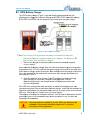
TM
TM70 Handheld
Wireless Remote Control System
User Manual
U003.5-TM70_HH_SYS-R
©2007-2011 Cervis, Inc.
TM70 Handheld Wireless Remote Control
This document is the property of Cervis, Inc. and cannot be copied, modified,
e-mailed, or reproduced without the express prior written consent of Cervis, Inc.
Cervis, Inc. reserves the right to change this manual or edit, delete, or modify
any information without prior notification.
FCC Statements
15.19 – Two Part Warning
This device complies with Part 15 of the FCC rules. Operation is subject to the
following two conditions:
(1) This device may not cause harmful interference and
(2) This device must accept any interference received, including interference that
may cause undesired operation.
15.21 – Unauthorized Modification
NOTICE: The manufacturer is not responsible for any radio or TV interference caused
by unauthorized modifications to this equipment. Such modifications could void the
user’s authority to operate the equipment.
Cervis, Inc.
Visit our Web site at:
www.cervisinc.com
IKUSI and the IKUSI logo is a trademark of IKUSI. 20014 San Sebastian Spain
© 2007-2011 Cervis, Inc. All rights reserved. Content is subject to change without notice.
System User Manual
Table of Contents
List of Figures .............................................................................................................................. ii
List of Tables ................................................................................................................................ ii
Welcome to Cervis ....................................................................................................................... 1
1.0 TM70 System Description ................................................................................................... 2
2.0 Safety Instructions ............................................................................................................... 5
2.1 What You MUST Do .......................................................................................................... 5
2.2 What You MUST NOT Do.................................................................................................. 5
3.0 System Component Installation ......................................................................................... 7
3.1 Transmitter Battery ........................................................................................................... 7
3.2 CB70 Battery Charger ...................................................................................................... 9
3.2.1 Charging Tips ............................................................................................................. 10
3.3 Receiver Installation ....................................................................................................... 10
3.4 Starting Up....................................................................................................................... 13
4.0 Using the System ............................................................................................................... 15
4.1 General Instructions ....................................................................................................... 15
4.2 Battery Level Monitor ..................................................................................................... 15
4.2.1 LCD Option Power Level Display ............................................................................... 16
4.3 Programming a Spare Transmitter ............................................................................... 16
4.3.1 Transfer EP70 From Transmitter to Spare Transmitter ............................................. 16
4.3.2 Copy Receiver EP70 to Transmitter EP70 ................................................................. 17
4.4 Programming the Machine Identification in LCD Transmitters ................................. 19
4.5 LCD Display Analog Feedback Calibration .................................................................. 20
4.5.1 Calibrating Analog Feedback ..................................................................................... 20
4.6 Range Limiter .................................................................................................................. 21
4.6.1 Infrared Sensor........................................................................................................... 22
4.6.2 Infrared Transmitter .................................................................................................... 23
4.6.3 Installation .................................................................................................................. 23
4.6.4 Technical Characteristics of the LA70........................................................................ 24
5.0 Maintenance ....................................................................................................................... 25
5.1 Precautions ..................................................................................................................... 25
5.2 Fault Identification .......................................................................................................... 25
5.2.1 Transmitter ................................................................................................................. 25
5.2.2 Receiver ..................................................................................................................... 25
5.3 Returning Equipment for Repair ................................................................................... 26
5.4 Spare Parts ...................................................................................................................... 27
5.5 Common Spare Parts Identification (limited)............................................................... 29
6.0 Warranty.............................................................................................................................. 32
©2007-2011 Cervis, Inc.
i
TM70 Handheld Wireless Remote Control
List of Figures
Figure 1. TM70 System Components with a TM70/1 Transmitter ............................................. 2
Figure 2. TM70/2 Transmitter Layout ........................................................................................... 3
Figure 3. CB70 Battery Charger ................................................................................................... 9
Figure 4: Typical MOV Wiring Across Contactor Coil ............................................................. 10
Figure 5. Receiver Footprint ....................................................................................................... 11
Figure 6. Receiver Antenna with Extension Kit ........................................................................ 11
Figure 7. Main Board Connections, Relays, and LEDs ............................................................ 12
Figure 8. TM70 Transmitter Details ............................................................................................ 14
Figure 9. Extracting the EP70 Memory Module ........................................................................ 17
Figure 10. Receiver EP70 Module Location .............................................................................. 18
Figure 11. TX Pushbutton/Switch Numbers/Names ................................................................. 18
Figure 12. Transmitter Button Locations .................................................................................. 19
Figure 13. Range Limiter Application Examples ...................................................................... 22
Figure 14. IR Limiter Working Area ............................................................................................ 23
Figure 15. TM70/1 2301090 Pushbutton Transmitter ............................................................... 29
Figure 16.TM70/2 2301091 Pushbutton Transmitter ................................................................ 29
Figure 17. TM70/1 2301090-B4-DLA Display Handheld Transmitter ....................................... 30
Figure 18. TM70/1 2301091-B4-DLA Display Handheld Transmitter ....................................... 30
Figure 19. PS70/1 DLA Upper 2303801 and PS70/2 DLA Upper 2303811............................... 31
List of Tables
Table 1. TM70/02 Transmitter Component Descriptions ........................................................... 3
Table 2. TM70 Main Specifications .............................................................................................. 4
Table 3. Receiver LED States During Power-Up ....................................................................... 13
Table 4. Receiver LEDs Upon Receiving a Transmitter Signal ............................................... 14
Table 5. LCD Power Level Interpretation................................................................................... 16
Table 6. Transmitter Layout ........................................................................................................ 18
Table 7. Transmitter Status LED Fault Identification ............................................................... 25
Table 8. Receiver Status LED Fault Identification .................................................................... 26
Table 9.Available Spare Parts..................................................................................................... 27
CAUTION
The instructions in this manual must be read carefully and strictly
adhered to in order to:
•
install and use the system properly
•
keep it in working condition and
•
reduce the risks of misuse.
Do not use this system on machines used for lifting people.
Do not use this system in potentially explosive atmospheres.
Any use other than that specified in this manual is DANGEROUS.
ii
U003.5-TM70_HH_SYS-R
Welcome to Cervis
Thank you for choosing the TM70 Wireless Remote Control. We here at Cervis believe
you have purchased one of the most reliable industrial radio control systems available.
Specializing in wireless remote controls for mining and industry, we offer you over 60
years of combined machine control experience. We custom design and manufacture
control systems for OEM’s worldwide. We are dedicated to our customers’ success—
your needs, paramount to our success, have allowed us to become a leading innovator
of wireless machine control technologies.
We are honored to have served some of the most demanding and rewarding customers
in the world over the last 15 years. Called upon to solve the most challenging radio
remote control problems in the industry, our systems have earned a world-wide
reputation for affordability, superior engineering, ruggedness, and reliability.
Our goal is to provide our customers with the safest, most reliable wireless radio remote
control available at an affordable cost. And to meet our goal, we develop and use the
highest level, proven state-of-the-art technology backed by unparalleled customer
support. Our systems increase our customers’ safety and productivity—no matter how
demanding the environment.
We are extremely pleased to have you as a customer, and we thank you for your
purchase.
TM70 Handheld Wireless Remote Control
1.0 TM70 System Description
A standard TM70 system is comes complete with:
•
One (1) Transmitter – either a TM70/1 or a TM70/2
•
One (1) R70 Receiver
•
One (1) CB70 Battery Charger
•
Two (2) BT06K Batteries
•
One (1) Antenna (internal or external)
The battery operated TM70/1 and TM70/2 push-button style transmitters are designed
for the remote control of industrial equipment. An operator using a handheld transmitter
can determine the safest location from which to carry out an operation. The receiver is
connected to the electrical system of the machine to be operated. Table 2 below lists
the Main Specifications of the TM70 system.
Receiver
CB70 Charger with Batteries
Transmitter
Figure 1. TM70 System Components with a TM70/1 Transmitter
2
U003.5-TM70_HH_SYS-R
System User Manual
Figure 2.
2 TM70/2 Tra
ansmitter Lay
yout
T
Table
1. TM70
0/02 Transmiitter Compon
nent Descriptions
Figure 2
Reference
R
Compone
ent
1
IR Range Limiter
L
(option
nal)
2
LCD (optional display)
3
Diagnostic LED
4
Two-step pushbuttons
p
5
Maintained
d or spring retturn rotary sw
witch
6
Safety key switch (Powe
er ON/OFF)
7
Warning/Sttart switch
8
CAT3 Stop
p switch
9
Shock abso
orbers
10
Portable EE
EPROM
11
Battery
©2007-20
011 Cervis, Inc.
I
3
TM70 Handheld Wireless Remote Control
Table 2. TM70 Main Specifications
TM70
Frequency band
914.150 – 915.875 MHz
Response Time
100 ms
Temperature Range
0 to 150 °F (-20 to 65 °C)
ERP < 1mW
T70/1 and T70/2 Transmitters
IP65
Protection
R70/13 and R70/21 Receivers
48, 115, 230 VAC ± 10% -- 50/60 Hz
Power Supply
Optional
12 or 24 VDC
Consumption
20 mW
Relays
230 VAC/8A
STOP Relays
230 VAC/6A
Protection
IP65
Electrical Security
Class II (EN50178)
CB70 Battery Charger
Power Supply
12/24 VDC, 115 VAC
BTO6K Batteries
4
Voltage
4.8 V
Capacity
750 mAh NiMH
Charging Temperature
+41 to +95°F (0 to 35°C)
Battery Life
16 hrs. @ 15% duty cycle
U003.5-TM70_HH_SYS-R
System User Manual
2.0 Safety Instructions
These instructions must be read carefully in order to install and
use the system properly, to keep it in safe working condition,
and to reduce the risks of misuse.
CAUTION
Do not use this system on machines used for lifting people.
Do not use this system in potentially explosive atmospheres.
Any use other than that specified in this manual is
DANGEROUS.
Strict adherence to the following instructions is a MUST.
9Note: To comply with FCC RF exposure compliance requirements, this device and
its antenna must not be co-located or operating in conjunction with any other
antenna or transmitter.
2.1 What You MUST Do
•
Strictly adhere to the installation instructions contained in this manual.
•
Make sure that professional and competent personnel carry out the
installation.
Make sure that all site and prevailing safety regulations are fully followed.
•
•
Make sure that this manual is permanently available to the operator and
maintenance personnel.
•
Keep the transmitter out of reach of unauthorized personnel.
•
Remove the transmission key when the transmitter is not in use.
At the beginning of each work day, check to make sure that the Stop Button
•
and other safety measures are working.
•
When in doubt, press the Stop Button.
•
Whenever several systems have been installed, make sure the transmitter
you are about to use is the right one. Identify the machine controlled by the
transmitter on the transmitter label (customer supplied).
•
An audible or visual warning device indicating the machine is electrically
active and that the transmitter has control should be installed on the machine.
•
Service the equipment periodically.
•
When carrying out repairs, only use parts supplied by Cervis dealers.
2.2 What You MUST NOT Do
•
Never make changes to the system that have not been studied and approved
by Cervis.
©2007-2011 Cervis, Inc.
5
TM70 Handheld Wireless Remote Control
•
•
6
Never power the equipment with anything other than with the specified power
supply.
Never allow unqualified personnel to operate the equipment.
•
Never leave the equipment ON after use. Always use the ON/OFF Key or
the Stop Button to avoid accidental movements.
•
•
•
Never use the system when visibility is limited.
Never abuse the transmitter. Avoid dropping.
Never use the system if failure is detected.
U003.5-TM70_HH_SYS-R
System User Manual
3.0 System Component Installation
3.1 Transmitter Battery
CAUTION
THE BATTERIES MUST BE INITIALLY CHARGED
BEFORE USE. Batteries must be charged for a full twelve
(12) hours before they can be installed in the transmitter.
Using a battery before initially charging will shorten its life
span and can possibly result in an immediate degradation
of service.
9Note: You must fully charge the batteries before installing and using in the
transmitter. It takes twelve (12)hours to initially charge or recharge an
exhausted battery. Once a battery is charged, do NOT charge it again until the
transmitter indicates a low charge. You will shorten the battery life by charging
it before it is exhausted. To guard against disruption of service, be sure to
have one battery fully charged or in the process of being fully charged while
the other is in use at all times.
Upon initial start-up, place a fully charged battery in the transmitter. Continue to use it
until the transmitter LED slowly flashes red. The flashing LED indicates you have
approximately five (5) minutes of operation until the transmitter automatically shuts
down (see Topic 0 Use the following instructions to properly operate the equipment:
1. Attach the harness to the transmitter to prevent the equipment from
falling.
2. Make sure of the transmitter you are going to use. Verify that the machine
you want to operate matches the transmitter identification label—the label
allows the operator to identify the machine before starting the equipment.
3. Install a fully charged battery into the transmitter.
4. Make sure all command controls are in the neutral position. All the
command controls associated with active motions must be in the neutral
position (inactive) to enable the transmitter.
5. Turn the ON/OFF key ON (clockwise) to enable the transmitter.
6. Pull out the Stop Button. The LED should pulse green telling you the
transmitter is ready for use.
9Note: If you find that the Stop Button is already pulled out, you must push it in and
then pull it out again. This sequence permits proper operation of the Stop
circuit. If the unit has experienced a time-out auto-disconnect, it is not
necessary to repeat the Stop Button procedure; instead, push and hold the
START Button for one (1) second.
7. Press and hold the START Button. This activates the warning/start
alarm if one is installed on the crane/machine and indicates to you the
receiver is under your control.
©2007-2011 Cervis, Inc.
7
TM70 Handheld Wireless Remote Control
8. The green LED should light indicating that the transmitter is now
transmitting. Now when any of the transmitter command pushbuttons are
pressed, the corresponding motion is activated.
9. Press the Stop Button or turn the ON/OFF Key counter clockwise to
turn the transmitter OFF.
Battery Level Monitor). If the Stop Button is pushed during the time the LED is flashing,
all control functions immediately cease and the transmitter will not start again until a
fresh battery is installed. It is recommended to put the machine you are controlling in a
safe state or safe place during this five minute warning so that it will not pose a hazard
while you are changing the exhausted battery with a fully charged battery.
CAUTION
If the STOP button is pushed during the time the LED is indicating an
imminent shutdown, be aware that the transmitter will not restart until a
fresh battery is installed. Be sure to place the machine your are
controlling in a safe state or place during the warning period so that it
does not pose a hazard while the battery is being changed.
Under normal duty cycles, you can expect approximately 10 to 16 hours (cumulative) of
actual usage before a battery is exhausted and needs to be recharged. An exhausted
battery will take approximately 12 hours to become fully charged.
9Note: A battery can be left on the charger for extended periods of time without
damage to either the battery or the charger.
8
U003.5-TM70_HH_SYS-R
System User Manual
3
3.2
CB70
0 Battery Charger
The CB7
70 battery ch
harger, Figurre 3, has two
o charging compartment
c
ts that can
simultaneously charg
ge two batte
eries. Batteryy types BT06
6K (TM70 tra
ansmitter ba
attery)
T12, and BT
T20K can be
e charged in any combination using the
t charger.
BT06, BT
Figure
e 3. CB70 Ba
attery Charge
er
9Note: Thhe Charging LED lights when
w
the batttery is first seated
s
in the
e cradle
ind
dicating the battery
b
is pro
operly seated and is cha
arging. The Charging
C
LE
ED
goe
es out after when the ba
attery is charrged.
1. Co
onnect the charger
c
to the proper pow
wer source using
u
adapto
or supplied
for your system.
When ins
stalling the battery
b
charg
ger, bear in mind that the batteries must
m
be charged at
temperattures over 41ºF (5ºC) an
nd that the power
p
supplyy must be lefft for the enttire time
that it tak
kes to charg
ge, without in
nterruption. Also
A
rememb
ber that the charger musst not be
left in dirrect sunlight as the batte
eries will not become fullly charged at
a temperatures
exceedin
ng 95ºF (35ººC).
2. Place the battteries in the charger. The
e LED’s sho
ould illuminatte indicating
g
that recharging is in proce
ess. Comple
ete rechargin
ng takes 12 hours.
h
Ba
atteries mayy remain in th
he charger fo
or an unlimitted period off time after
they are fully charged.
c
If the LED does not illuminate
i
wh
hen the battery is seated
d for chargin
ng, there is an
a
improperr connection
n. Remove th
he battery fro
om the charger, check that the term
minals are
clean and unobstruccted, and resseat the batte
ery firmly in its cradle; check to see that the
LED is on. Should th
his fail, conta
act Cervis Customer Sup
pport.
acity of the batteries
b
deccreases with
h use. Their life span is estimated
e
to be 500
The capa
rechargin
ng cycles, but this depen
nds largely on
o the condiitions of use, for which th
he
following
g is recomme
ended:
CAUTIO
ON
Only use
u batterie
es certified by Cervis. When the batteries
b
arre
exhau
usted, they should be safely
s
dispo
osed of or recycled
r
accorrding to loca
al regulation
ns.
©2007-20
011 Cervis, Inc.
I
9
TM70 Handheld Wireless Remote Control
3.2.1 Charging Tips
•
•
•
•
•
CAUTION
Do not recharge the battery until it is completely flat (fully discharged). The
transmitter indicates when the battery is nearing a charge cycle when the
LED flashes red; this also indicates the transmitter will switch OFF in five (5)
minutes. See Topic 0 below.
Always charge the batteries at temperatures between 41ºF and 95ºF.
Avoid short-circuits between the battery contacts. Do not carry charged
batteries in toolboxes or next to other metal objects (keys, coins, etc.).
Always keep the contacts clean.
Never leave batteries in direct sunlight.
Never carry batteries in your pockets with other metal objects where a short
across the terminals may occur resulting in burns or injuries.
3.3 Receiver Installation
CAUTION
Make sure the machine on which the receiver is to be attached is
disabled while during installation.
Turn off the main line disconnect switch. Check the power supply
voltage. MAKE SURE THE POWER SUPPLY IS OFF.
For a crane, park the crane and position the end stops at a suitable
distance so that other cranes on the same runway do not hit it. If end
stops are not available, use appropriate signs instead.
Keep the work area free from unnecessary clutter.
Wear protective clothing.
9Note: Before installing the receiver, make sure that the outputs diagram supplied
with the system is available.
9Note: Installations subject to vibration should install the optional Shock Absorber Kit
part # 1166074 available at Cervis. The kit has four absorbers that you place
between the receiver and the mounting surface as per the kit directions.
9Note: Always mount the receiver and antenna away
from any intense radio or electric disturbance
sources.
9Note: When using contactors with the system, it is
advisable to use the MOV’s provided by installing
them across the coil of the contactors as shown
in Figure 4.
Figure 4: Typical MOV Wiring
Across Contactor Coil
10
U003.5-TM70_HH_SYS-R
System User Manual
9Note: If necessary, it is possible to improve signal reception by using the extension
cables and external antenna kit. See Figure 6 below.
1. Find a suitable location for the receiver with clear access to the
transmitter radio signal. Figure 5 below shows the footprint of the receiver
and illustrates the distance between the mounting holes.
Figure 5. Receiver Footprint
J501 (Antenna) J502 (Cable) J503 (Bracket)
Figure 6. Receiver Antenna with Extension Kit
©2007-2011 Cervis, Inc.
11
TM70 Handheld Wireless Remote Control
2. Follow the Outputs Diagram supplied with the system to connect the
power supply and the receiver outputs on the relay board plug-in
terminals. The Output Diagram indicates the relationship between the
transmitter commands and the receiver outputs.
•
The STOP relays K15 and K16 are in series and must be connected to the
main contactor coil circuit.
•
The K2/START is activated once the Warning/START command is held
down.
•
The K1/SEC relay is a security relay. It is activated when certain commands
predefined as Active—commands that give rise to movements—are
activated.
SIGNAL
POWER
HARDOK
ID
DATA
K16
K14
K13
K2
K15
K12
K1
K11
K10
K9
K5
K4
K3
K8
K7
K6
FUSE 1A
K14
+/ AC
N230/ AC
PE
N115/ AC
K13
STOP
K2
K12
K1
K11
K10 K9
K8
K7
K6
K5
K4
K3
- / DC
N48/ AC
Figure 7. Main Board Connections, Relays, and LEDs
3. Select the appropriate voltage on the receiver.
4. Be certain to connect the ground cable.
CAUTION
Use only fireproof cables for connections.
12
U003.5-TM70_HH_SYS-R
System User Manual
3.4 Starting Up
1. Once the receiver has been connected, disconnect the power supply to
the motors—by removing the fuses for example—and then power up the
receiver. The receiver enters into a SCANNING mode upon power-up;
the receiver LED power-up states are defined in Table 3.
Table 3. Receiver LED States During Power-Up
LED
State
Indication
POWER
ON
Power supply is correct
HARDOK
ON
Absence of faults on the boards
SIGNAL
OFF
Blinks
Channels are signal free
An RF signal on the channels
OFF
Another TM70 system is not active in the area
Blinks
Another TM70 system is active in the area
OFF
System Transmitter not on.
DATA
ID
2. Turn the transmitter (Figure 8) ON to OPERATION Mode as follows:
a. Place a charged battery in the transmitter.
b. Turn the Contact Key clockwise to ON.
c. Push in and then pull out the STOP Button. The transmitter LED
flashes orange once, and then illuminates green for three (3)
seconds. If the transmitter has an LCD, it displays the
identification of the machine and the battery level.
d. Press and hold the START Button. The green LED should now
light indicating that the transmitter is transmitting. Release the
START Button.
At this point the STOP relays K15 and K16 are energized as long as the TX is active.
These relays are typically used to control a main-line contactor, hydraulic pump, or
other device that determines that the machinery is on.
The K2/START relay is energized when the START Button is pushed. It is typically is
also connected to a warning device.
©2007-2011 Cervis, Inc.
13
TM70 Handheld Wireless Remote Control
Crane ID Label
Option: LCD Display
Option: IR Range Limiter
LED
Command Button
Contact Key
Start Button
Stop Button
Figure 8. TM70 Transmitter Details
Table 4 below shows the receiver LEDs upon receiving a signal from the transmitter.
Table 4. Receiver LEDs Upon Receiving a Transmitter Signal
LED
State
Indication
POWER
ON
Power supply is correct
HARKOK
ON
Defects have not been detected on the board
SIGNAL
ON
Channels are signal free
DATA
ON
Data received has a correct format
ID
ON
Receiver has recognized the transmitter ID code
3. Press any of the transmitter’s movement pushbuttons. Its corresponding
relay is energized. In case of an active movement, the safety relay
K1/SAFETY is also energized.
4. Check to make sure all the other movements work as described in Step 3.
5. Turn off the transmitter using the STOP Button, and make sure that
when doing so the relays are not energized and the DATA, ID, and
SIGNAL LEDs go out. They should behave exactly as when in the
SCANNING mode.
6. Reconnect the power supply to the motors, move to a safe position, and
check to see if all the movement pushbuttons and the STOP Button
correctly function.
14
U003.5-TM70_HH_SYS-R
System User Manual
4.0 Using the System
4.1 General Instructions
Use the following instructions to properly operate the equipment:
7. Attach the harness to the transmitter to prevent the equipment from
falling.
8. Make sure of the transmitter you are going to use. Verify that the machine
you want to operate matches the transmitter identification label—the label
allows the operator to identify the machine before starting the equipment.
9. Install a fully charged battery into the transmitter.
10. Make sure all command controls are in the neutral position. All the
command controls associated with active motions must be in the neutral
position (inactive) to enable the transmitter.
11. Turn the ON/OFF key ON (clockwise) to enable the transmitter.
12. Pull out the Stop Button. The LED should pulse green telling you the
transmitter is ready for use.
9Note: If you find that the Stop Button is already pulled out, you must push it in and
then pull it out again. This sequence permits proper operation of the Stop
circuit. If the unit has experienced a time-out auto-disconnect, it is not
necessary to repeat the Stop Button procedure; instead, push and hold the
START Button for one (1) second.
13. Press and hold the START Button. This activates the warning/start
alarm if one is installed on the crane/machine and indicates to you the
receiver is under your control.
14. The green LED should light indicating that the transmitter is now
transmitting. Now when any of the transmitter command pushbuttons are
pressed, the corresponding motion is activated.
15. Press the Stop Button or turn the ON/OFF Key counter clockwise to
turn the transmitter OFF.
4.2 Battery Level Monitor
TM70 transmitters are equipped with a battery-level monitoring circuit. When the charge
level drops below a pre-defined limit, the transmitter LED flashes red indicating the
transmitter will switch OFF and be disabled in five (5) minutes. When the transmitter is
disabled, the machine’s main contactor is de-energized. If the Stop Button is pushed
during this 5-minute warning period, the transmitter will not start again until a
fresh battery is installed.
CAUTION
For safety sake, the load must be located to a safe position and area
during the 5-minute warning prior to Low Battery automatic shutdown.
Beware: If the STOP Button is pushed during this warning time,
you cannot use the transmitter again until a fresh battery is
installed.
©2007-2011 Cervis, Inc.
15
TM70 Handheld Wireless Remote Control
4.2.1 LCD Option Power Level Display
Transmitters with the LCD option indicate the battery power level by showing
segments—black dashes—in the display. The more dashes shown, the more charged
the battery. Power levels are interpreted in Table 5.
Table 5. LCD Power Level Interpretation
Segments Displayed
Battery Charge
Three segments
Greater than 50%
Two segments
Between 10% and 50%
One segment
Between 5% and 10%
None
Less than 5%
9Note: The transmitter will automatically go to STAND BY mode after four (4)
minutes of inactivity. Standby mode is indicated by 3-second green LED
pulses. Press the START Button to restart the transmitter. The 4-minute
default can be changed or eliminated through a software modification. If a
change is desired, please contact Customer Service.
CAUTION
Keep in mind at all times that you are controlling a moving piece
of machinery. You must strictly adhere to the safety instructions
described in Section 2.0 of this manual.
4.3 Programming a Spare Transmitter
If a transmitter is damaged, it is possible to quickly restore service by transferring the
EP70 Memory Module EEPROM from the original damaged transmitter to a similar
spare transmitter. This ensures that you use the exact parameters of the original in the
spare. The EP70 Memory Module EEPROM is easily accessible from the exterior of the
transmitter. To transfer the EP70 Memory Module:
4.3.1 Transfer EP70 From Transmitter to Spare Transmitter
1. The EP70 module is a part of the cover located on the back of the
transmitter. Turn the damaged unit over and remove the two screws as
shown in Figure 9A. If there is an EEPROM in the spare transmitter,
remove the cover screws on it, too.
2. Extract the EP70 module from the damaged transmitter as shown in
Figure 9B. Handle module during the transfer by touching only the cover;
avoid touching the actual EEPROM located beneath the cover.
3. Install the original transmitter EP70 module into the spare transmitter. The
module is keyed so that it will only fit in one way.
4. Install the cover screws on the spare transmitter.
16
U003.5-TM70_HH_SYS-R
System User Manual
A
B
Figure 9. Extracting the EP70 Memory Module
4.3.2 Copy Receiver EP70 to Transmitter EP70
In cases where the damage to the transmitter prevents removal of the resident EP70
module, the spare transmitter can be programmed using the EEPROM module found
inside the receiver. To program a spare EP70 using the receiver EEPROM:
1. Remove the cover from the receiver and pull the EP70 from its location by
grasping the module by its edges—avoid touching the actual component
beneath—and lift the module from its pins by pulling away from the
component board. See Figure 10 below for possible EEPROM location.
1. Ensure the spare transmitter is OFF. Remove the EP70 Memory Module
in the transmitter as shown in Figure 9 above.
2. Insert the EP70 module you removed from the receiver into the
transmitter socket.
3. Turn on the transmitter ON/OFF key to ON and pull the STOP Button
out. The LED will pulse orange, and then green for 15 seconds. See
Table 6 below for button function layouts of transmitters.
4. To copy the EP70 Memory Module contents into the internal memory of
the transmitter, press transmitter Pushbutton 6 (see Figure 11) followed
by START; keep both buttons simultaneously pressed for five (5)
seconds. The LED will blink orange during the copying process. (In the
LCD display models, the word ‘Reading...’ will display.)
5. When the copying process is complete, remove the receiver EP70
module from the transmitter and replace it into the receiver.
6. Insert the original transmitter EP70 module into the transmitter socket.
Press transmitter pushbutton 6 (see Figure 11). The LED will flash
orange indicating the resident EP70 Memory Module is being written to
with the stored receiver parameters. (In the LCD display models, the word
Writing... will display.)
©2007-2011 Cervis, Inc.
17
TM70 Handheld Wirreless Remotte Control
Figure 10. Receiver EP
P70 Module Location
L
Tab
ble 6. Transm
mitter Layoutt
Ref. Compone
ent Ref. Component
C
t
1
IR Range
Limiter
(optional)
7
Warning/Startt
W
s
switch
2
LCD
(optional)
8
CAT3 Stop
C
s
switch
3
Diagnostic
LED
9
Shock
S
a
absorbers
4
Two-step
ns
pushbutton
10
Portable
P
E
EEPROM
5
Maintained or
spring returrn
switch
11
B
Battery
6
Safety key switch
Fig
gure 11. TX Pushbutton/S
P
Switch Numb
bers/Names
18
1
U003
3.5-TM70_HH
H_SYS-R
System User Manual
4.4 Programming the Machine Identification in LCD Transmitters
Transmitters with the optional LCD display permit the operator to program a machine
identification label of up to 24 characters. The identification displays upon transmitter
start-up.
You can edit/introduce this text as follows when first starting the transmitter (see Figure
12):
1. Install a battery and turn the ON/OFF key to ON.
2. Push in and then pull out the STOP Button. You the LED should pulse
orange followed by green pulses.
3. Press pushbutton 4 to the second step and then push the START
Button. Keep both pressed simultaneously for 2 seconds. You will enter
the EDITING mode.
4. Once you have entered the EDITING mode, the display will show
CRANE ?? with the first character blinking. From this point you can edit
the name of the machine using pushbuttons 1 to 4. Button functions are
as follows:
•
Pushbutton 1: Scroll the list of established characters in descending order.
•
Pushbutton 2: Scroll the list of established characters in ascending order.
•
Pushbutton 3: Return to the previous character in the display.
•
Pushbutton 4: Validate the displayed character and move to the next
character to the right.
•
Push START to store the edited text. LCD will show the message SAVED
for two (2) seconds.
5. Once the last character has been edited, exit EDITING mode by pressing
the STOP Button.
Figure 12. Transmitter Button Locations
©2007-2011 Cervis, Inc.
19
TM70 Handheld Wireless Remote Control
4.5 LCD Display Analog Feedback Calibration
Analog feedback systems must have the Display and Analog Feedback options. The
analog input must be calibrated upon startup. Transmitters with the display option allow
the operator to calibrate the analog input using the display three digit value and a
comma; and, a measurement unit of up to three characters.
9Note: Calibration generates a linear interpolation of the possible values. This means
that it can be used with all systems that generate a linear analog output. For
non-linear systems, the interpolation will display an incorrect value.
4.5.1 Calibrating Analog Feedback
The transmitter must be within operating range of the receiver during this
procedure.Use Figure 12 to reference pushbutton and key switch locations on the
transmitter.
1. Insert a fully charged battery into the transmitter and turn the Key Switch
to ON.
2. Push and then pull-out the STOP Button.
3. Place a known load on the crane to introduce the first value.
4. Enter the Calibration mode by pressing Pushbutton 4 to the second
speed; continue to hold the button down.
5. Push and hold the START Button simultaneously with the pushbutton 4
until CONFIG appears on the display.
6. Press Pushbutton 4 to enter the MENU.
7. Use Pushbuttons 1 and 2 to navigate through the menu until you find
CALIBRATION.
8. Press Pushbutton 4 again. You will enter a Calibration submenu where
you can navigate to selections Value 1, Value 2, and Units by using
Pushbuttons 1 and 2.
9. Navigate to the desired submenu, Value 1, and press Pushbutton 4 to
enter that submenu. Note that the receiver will start up, but you will not
have control over crane motion. The transmitter must communicate with
the receiver in order for the information from the analog input to be sent to
the transmitter. While in a submenu, you can use Pushbuttons 1 through
4 as follows:
•
•
•
•
Pushbutton 1 – Used to move through character list in descending order.
Pushbutton 2 – Used to move through the character list in ascending order.
Pushbutton 3 – Used to return to the previous character in the list.
Pushbutton 4 – Used to select the chosen character for that digit position
and move to the next digit position.
10. Once a corresponding value is assigned to the suspended load, the
display will show three digits plus a comma. Make sure the value
displayed is accurate.
20
U003.5-TM70_HH_SYS-R
System User Manual
11. Press the START Button to Save the displayed value. The value will be
memorized for that calibration item. Communication with the receiver will
stop.
12. Press Pushbutton 1 to return to the previous menu to edit the Units.
Units can be no more than three (3) characters.
13. Press STOP and restart the crane. Replace the current load with another
known load.
14. Repeat process Steps 9 through 12 to calibrate Value 2.
15. Press STOP and restart the crane.
The system will now be ready for service.
9Note: Data appearing in the display will be inconsistent and unreliable until
calibration is performed.
9Note: Calibration allows negative values.
9Note: Modified feedback calibration data is not automatically updated in the receiver
EEPROM. The new information must be copied from the transmitter EEPROM
into the receiver EEPROM.
Calibration Example of a Load Cell
1. Get into Calibration mode. Enter Value 1 to represent the hook with no
load.
2. Press START to validate the entry. Turn the transmitter OFF.
3. Start the system again and raise a known load.
4. Turn the transmitter OFF and then restart.
5. Enter Calibration mode again. Set Value 2.
6. Press START to validate the entry.
7. Press Pushbutton 1 to edit the Units.
8. Press START to validate the Units.
9. Turn the transmitter OFF.
The equipment should now be calibrated and ready for use.
4.6 Range Limiter
TM70 radio remote control systems LA70 Infrared Range Limiter transmitter option
prohibits the system from being operated outside a defined working area. The operator
must be within Line-Of-Sight of the LA70 transmitter to control the machine.
The system consists of one or more LA70 Infrared transmitters. The LA70 transmitter is
installed in a fixed position or on the controlled crane and positioned to cover the
©2007-2011 Cervis, Inc.
21
TM70 Handheld Wireless Remote Control
targeted working zone as shown in Figure 13. Range Limited TM70 RF transmitters are
equipped with an infrared sensor that receives the information from the LA70
transmitter, analyzes the information, and then acts as a permissive. If the transmitter
does not receive the infrared data within a pre-determined time (factory setting is four
(4) seconds), the outputs are deactivated.
Figure 13 shows some LA70 IR Range Limiter application examples.
B
A
C
Figure 13. Range Limiter Application Examples
4.6.1 Infrared Sensor
As the system or operator moves, an infrared sensor located in the TM70 remote
control transmitter receives infrared information as it is transmitted from the LA70
transmitter. The remote microprocessor gathers the sensor information and checks for
the crane or machine ID. If the operator is too far away from the LA70, the sensor stops
receiving an IR signal and the TM70 transmitter LED begins to flash RED warning the
operator that the sensor must be back within signal range within four (4) seconds (the
system default). If the operator fails to get back into range within the allotted time, all
active commands are stopped; however, the RF communication is maintained with the
receiver and remains in control of the main-line contactor and the selection commands.
The operator must move the TM70 transmitter into the defined working area, or zone, to
regain control the crane or machine. Movement commands must be disabled and
reestablished for control. Transmitters having displays will show the message “Out of
Range” while the transmitter is beyond working range.
Four (4) modes of operation are defined in the EEPROM:
1. Range Limiter Only At Startup (Electronic Key): The transmitter must be within
the define control zone upon startup.
2. Range Limiter Only In Operation: The transmitter can be started anywhere, but
control will only occur when the transmitter is within the defined limits of the
sensors.
3. Range Limiter At Startup And Operation: The transmitter functions only within
the sensor limited range.
22
U003.5-TM70_HH_SYS-R
System User Manual
4. Range Limiter Only As An Output Relay: The transmitter does not indicate if it is
in or out of range, but it does not mask an order. Information will be sent to the
receiver to process as an output command, or as an output condition in the relay
table.
4.6.2
Infrared Transmitter
The Infrared Transmitter installed on the crane
Figure 14. IR Limiter Working Area
h (m/ft)
D (m/ft)
d (m/ft)
6/19.7
24/78.7
10/32.8
8/26.3
32/104.9
13/42.7
10/32.8
40/131.2
17/55.8
12/39.4
48/157.5
20/65.6
14/49.9
56/183.7
23/7646
16/52.5
64/210
26/85.3
18/59
68/223.1
29/95.1
20/65.6
70/229.7
32/105
The working area is elliptical, and the area of influence is determined by how high
above the ground the IR transmitter is installed; the higher the transmitter, the greater
the area of influence. If the area of control is determined to be larger than that provided
by the LA70, multiple LA70s can be installed to increase the control area.
4.6.3
Installation
Make sure that the crane is switched OFF during assembly and
installation.
Make sure that the area is clear and proper safety apparel is used.
Make sure that the power supply to the crane is disconnected.
Make sure the earth ground cable is attached.
Use flame resistant cable for all connections.
•
•
•
•
•
Install the unit away from anything that can generate intense electrical
disturbances and light transmission.
Use the proper power supply.
Place the selector jumper in the MASTER position.
Select the desired programmed code in the transmitter EEPROM.
Communication wiring between multiple LA70 transmitters must be made
using shielded wires.
©2007-2011 Cervis, Inc.
23
TM70 Handheld Wireless Remote Control
In those cases where it is necessary to use more than one LA70 transmitter, connect
subsequent transmitter in series with each transmitter selector set as SLAVE.
4.6.4
Technical Characteristics of the LA70
Infrared Transmitter
24
Power Supply
48, 115, 230VAC ± 10%; 50/60Hz
Operation Temperature
-10 to +65°C
Protection
IP55
U003.5-TM70_HH_SYS-R
System User Manual
5.0 Maintenance
5.1 Precautions
This equipment is designed for use in an industrial environment. However, we
recommend you follow the instructions below to extend the life span of your remote
control system.
•
•
•
•
•
•
•
Use the harness provided with the transmitter to prevent the transmitter from
falling.
Do not clean the transmitter with solvents or pressurized water. Use a damp
cloth or soft brush.
Use and recharge the battery regularly as per the guidelines of Topic 3.1
aboveand Topic 3.2 above.
Check that the STOP Button is working every day.
Disconnect the receiver cables if welding is necessary on the machine.
Periodically check the condition of the transmitter rubber seals. Replace
immediately if they show signs of deterioration to ensure they remain
watertight.
Clean the battery contacts.
5.2 Fault Identification
Both the transmitter and receiver have status monitoring LEDs that help to identify
failures. The most common signals are contained in the tables below.
5.2.1 Transmitter
Table 7. Transmitter Status LED Fault Identification
LED
Indication
Solid Green
Transmitter transmitting normally. OPERATION Mode.
Green Pulses
Transmitter ready for Start-up. STAND BY Mode.
Red – Slow Flashing
Battery level low.
Red – Fast Flashing
EEPROM module is not plugged in.
Red – Double Flashing
Transmitter cannot start up because a motion command is present.
Red – Solid
Transmitter failure.
5.2.2 Receiver
In OPERATION mode the five LED’s must be lit as has described in section 3.4. If this
condition exists, press the transmitter motion pushbuttons and observe the response of
the output relays.
•
If the response is normal, the problem is not related to the remote control
equipment and the installation must be evaluated.
©2007-2011 Cervis, Inc.
25
TM70 Handheld Wireless Remote Control
•
If any of the relays are not activated, the problem is associated with the
remote control equipment. Observe the status of the LED’s and reference
Table 8 to determine the problem source.
Table 8. Receiver Status LED Fault Identification
LED
LIT
ON
OFF
SIGNAL
RF signal OK
RF signal detection in
SCANNING Mode
The receiver is not receiving
RF signals
POWER
Power Supply OK
HARDOK
Board OK
Power Supply NOT OK
Slow: fault in the board
Fast: error in EEPROM
Fault in the board
ID
ID Code OK1
ID NOT recognized
DATA
Is receiving the correct data
from a TM701
Fault in the board
1
DATA and ID LED’s show a weak flashing when data and the ID code are received correctly but the Start
command has not yet been received. Once START Button is pushed ON the DATA and ID LED’s will show the
standard strong flashing.
5.3 Returning Equipment for Repair
If you find a problem with the equipment:
1. Contact our Customer Service.
2. Discuss your problem with the Cervis technician. In many cases the
problem can be resolved over the telephone and thus not require you to
return any equipment.
3. When equipment is determined to need service, the technician will issue
an Return Material Authorization (RMA) number to you.
4. Return the defective device to our Customer Service Department. Please:
• Include a description of the problem and the status of the LEDs.
• Clearly mark your issued RMA number on the outside of the package.
9Note: Please address all equipment returned to Cervis, Inc. to the attention of our
Technical Service Department, together with a description of the problem and
the status of all LED’s. It is our intention to make the necessary repairs quickly
and return the system to you as soon as possible.
9Note: If the transmitter becomes inoperable, a spare can be quickly substituted by
following the instructions in APPENDIX A.
26
U003.5-TM70_HH_SYS-R
System User Manual
5.4 Spare Parts
Table 9.Available Spare Parts
Item
Part
Code
Transmitter
TM70/1
2301090
TM70/2
2301091
TM70/1 with Display & IR Sensor
2301090-B4-DLA
TM70/2 with Display & IR Sensor
2301091-B4 DLA
LE71/915
2303881
LE71/915/DLA (units with display or IR)
2303901
LE72/915
2303884
LE72/915/DLA (units with display or IR)
2303904
R70/13
2301092
R70/21
2301093
R70/29
2305087
LR71/915 (120VAC)
2303887
LR71DC/915 (24VDC)
2303893
LR72/915 (120VAC)
2303890
LR72DC/915 (12VDC)
2303896
R8 CAN (8 relay)
2303739
IN 0-10V
2303755
IN 0-450P (expansion)
2303758
EP70 EE-Prom
2303743
EE-prom modification
2300300
Pushbutton P70
2303670
Pushbutton cover CP70
1152023
Spring return switch 1-0-1 M70
2303770
Maintained switch 1-0-1 S70
2303760
Key lock K60
2300170
Emergency STOP pushbutton EMS60
2305127
Upper part PS70/1 SM
2303780
Upper part PS70/2 SM
2303790
Upper part PS70/1 DLA (display/IR, Stop, and buttons)
2303801
Upper part PS70/2 DLA (display/IR, Stop, and buttons)
2303811
Lower part PI70/1
2303677
Transmitter
Boards
Receivers
Receiver
Boards
Electronic
Circuits
Misc. Parts
©2007-2011 Cervis, Inc.
27
TM70 Handheld Wireless Remote Control
Item
Part
Code
Lower part PI70/2
2303678
Upper Transmitter Bumper
1151051
Lower Transmitter Bumper
1151052
Battery BT06K
2303692
Battery charger CB70, (without power supply)
2305002
Power supply for CB70, 115VAC
1106027
12VDC Power Adapter (lighter housing) for CB70
1095824
12VDC Lighter Connector for CB70
1095825
Shoulder Strap/Harness B60C (padded)
1175030
Protective case TM70/1 transmitter (Bag)
2305010
Protective case TM70/2 transmitter (Bag)
2305011
Receiver shock absorbers
1166074
Shoulder Strap B70 (for handheld transmitter)
1175022
TM70 Antenna Extension Cable (10ft.)
Misc. (cont.)
Please call Cervis
for part number:
(724) 741-9000
External Antenna Adapter
Antenna Mounting Plate/Ground Plane
TM70 External Antenna
Icons
Internal Antenna
2303720
Standard Set:
three white arrows; three black arrows; one Start/Horn
2303845
TM70/1 Blank
2303847
N, S, E, W; Up-Down Arrows; Start/Horn
2303848
9Note: The Available Spare Parts table may change without notice. For pricing, and
availability, please go to our Web site at www.cervis.net for contact
information; or, email Cervis Sales directly with you inquiry at
[email protected].
28
U003.5-TM70_HH_SYS-R
System User Manual
5.5 Common Spare Parts Identification (limited)
The following information can be used to correctly identify common parts you may need
before placing an order.
TM70/1 Internal Antenna
2303720
Upper Part PS70/1
2303780
LE71/915 Transmitter
Board 2303881
Pushbutton P70
2303670
Machine STOP Button
2305127
Lower Part PI70/1
2303677
Includes Upper/Lower
Bumpers
Figure 15. TM70/1 2301090 Pushbutton Transmitter
TM70/2 Internal Antenna
2303723
Upper Part PS70/2
2303790
LE72/915 Transmitter
Board 2303884
Pushbutton Cover
1152023
Maintain Switch
2303760
Key Lock
2300170
Lower Part PI70/2
2303678
Includes Upper/Lower
Bumpers
Figure 16.TM70/2 2301091 Pushbutton Transmitter
©2007-2011 Cervis, Inc.
29
TM70 Handheld Wireless Remote Control
LE71/915 DLA Transmitter Board
2303901
Set of Standard TM70 Icons
2303845:
3 White Arrows
3 Black Arrows
1 Start/Horn
Figure 17. TM70/1 2301090-B4-DLA Display Handheld Transmitter
LE72/915 DLA Transmitter Board
2303904
Figure 18. TM70/1 2301091-B4-DLA Display Handheld Transmitter
30
U003.5-TM70_HH_SYS-R
System User Manual
2303801
PS70/1 DLA
Upper
2303811
PS70/2 DLA
Upper
Both Upper Parts include all pushbuttons and a mounted STOP switch.
Figure 19. PS70/1 DLA Upper 2303801 and PS70/2 DLA Upper 2303811
©2007-2011 Cervis, Inc.
31
TM70 Handheld Wireless Remote Control
6.0 Warranty
Subject to the limitations below, Cervis warrants all of its products to be free from
material defects in material and workmanship. However, Cervis liability under such
warranty shall be limited to repair or replacement of any product which Cervis’
inspection shall disclose to have been defective. This warranty does not apply to any
products, which have been subject to abuse, mishandling, or improper use, and does
not include field labor of any type. Cervis’ quotation does not include price provision for
performance bond of indemnity. Therefore, the additional cost incurred to provide such
a bond shall be added to the total amount of the quote and paid by Purchaser. The
warranty period for the TM70 series equipment shipped hereunder is one (1) year and
covers all labor and materials manufactured by Cervis provided the Purchaser returns
them to the factory for repair. Defective items under warranty will be repaired or
replaced free of charge at Cervis’ discretion, during the one (1) year term of this
warranty. Freight and/or postage are not covered by said warranty and will be paid by
the purchaser. Any services rendered in the field will be performed at current rates for
time and travel at the discretion of Cervis and will be paid by the purchaser. All TM70
products of Cervis carry a warranty period of one (1) year. Batteries, cases, switches,
faceplates, foils, and such other items subject to normal wear and deterioration are not
included in the warranty. Cervis’ warranty period begins at system receipt after direct
shipment to Purchaser.
IN NO EVENT WILL CERVIS BE LIABLE FOR INDIRECT, SPECIAL, INCIDENTAL,
OR CONSEQUENTIAL DAMAGES. EXCEPT AS STATED ABOVE, CERVIS MAKES
NO REPRESENTATIONS OR WARRANTIES, EXPRESSED OR IMPLIED, NO
OTHER REPRESENTATION OR WARRANTY IS GIVEN, AND NO AFFIRMATION OF
CERVIS OR ITS REPRESENTATIVES BY WORD OR ACTION SHALL CONSTITUTE
A WARRANTY. THERE ARE NO WARRANTIES WHICH EXTEND BEYOND THE
ONE (1) YEAR PERIOD DESCRIBED HEREIN. CERVIS SPECIFICALLY DISCLAIMS,
AND PURCHASER HEREBY WAIVES, ANY WARRANTIES OF MERCHANTABILITY
OR FITNESS FOR PARTICULAR PURPOSE.
The warranty does not cover damage resulting from the following:
•
•
•
•
transport
incorrect installation
repairs or alterations made by personnel other than from CERVIS
obvious misuse or incorrect maintenance of the equipment.
Our Technical Service reserves the right to evaluate all break-downs and damage to
determine warranty
Under no circumstances will CERVIS be held responsible for delays or work stoppage,
accidents or expenses incurred as a result of equipment malfunctioning.
32
U003.5-TM70_HH_SYS-R
System User Manual
Cervis, Inc.
Visit our Web site at:
www.cervisinc.com
Cervis, Inc. in long time partnership with
IKUSI and the IKUSI logo is a trademark of IKUSI. 20014 SAN SEBASTIAN SPAIN
© 2007-2011 Cervis, Inc. All rights reserved. Content is subject to change without notice.
©2007-2011 Cervis, Inc.
33