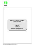
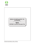
1
OPERATION & INSTALLATION MANUAL TM70 PUSHBUTTON TRANSMITTERS TM70Bi.v1.1.doc (10/03) Cervis reserves the right to modify this information without prior notification. I N DEX PAGE. 1. INTRODUCTION ........................................................................................................................................................ 2 2.- SYSTEM DESCRIPTION ......................................................................................................................................... 3 3.- SAFETY INSTRUCTIONS ........................................................................................................................................ 4 3.1.- WHAT YOU MUST DO ......................................................................................................................................... 4 3.2.- WHAT YOU MUST NOT DO ................................................................................................................................ 4 4.- INSTALLATION ......................................................................................................................................................... 5 4.1.- THE CB60 BATTERY CHARGER........................................................................................................................ 5 4.2.- RECEIVER ............................................................................................................................................................. 6 4.3.- STARTING UP ....................................................................................................................................................... 8 5.- USING THE SYSTEM .............................................................................................................................................. 10 6.- MAINTENANCE ...................................................................................................................................................... 11 6.1.- WARRANTY........................................................................................................................................................ 11 6.2.- PRECAUTIONS ................................................................................................................................................... 11 6.3.- FAULT INDENTIFICATION .............................................................................................................................. 12 6.4.- SPARES ................................................................................................................................................................ 13 ANNEX A - PROGRAMMING A SPARE TRANSMITTER. ................................................................................. 14 ANNEX B.- PROGRAMMING THE MACHINE IDENTIFICATION IN LCD TRANSMITTERS. ................... 15 TM70Bi.v1.1.doc (10/03) i 1.- INTRODUCTION Congratulations, you have purchased one of the safest most reliable radio contols available. Cervis Inc. has been honored to serve some of the most demanding and rewarding customers in the world. We've been called upon to solve the most challenging radio remote control problems in the industry. Our systems have earned a reputation for superior engineering, ruggedness, reliability and affordability. Our goal at Cervis is to provide our customers with the safest, most reliable wireless radio remote control available - at an affordable cost. We utilize the highest level of proven state-ofthe-art technology backed by unparalleled customer support. Our systems will increase our customer's safety and productivity, no matter how demanding the environment. Cervis Inc. has combined over 30 years of machine control experience. Specializing in wireless remote controls for the mining and industrial environments, we have custom designed and manufactured control systems for OEM's worldwide. Being dedicated to our customer's needs is paramount to our success and has allowed us to become one of the industry’s leading innovators of machine control technologies. Thank you for your purchase. We are very pleased to have you as a customer TM70Bi.v1.1.doc (10/03) 2 2.- SYSTEM DESCRIPTION The TM70/1 and TM70/2 push-button style transmitters are designed for the remote control of hoists and cranes, and are particularly suitable for applications when the operator needs to be able to choose the best location from which to carry out an operation. The system consists of a transmitter for selecting commands and a receiver, which is connected to the electrical system of the machine to be operated. The system also comes with a battery charger and two rechargeable batteries. The main specifications are as follows: The TM70 Frequency band 914.150 - 915.875 MHz; ERP <1mW Optional: 433,050 - 434,040 MHz; ERP <1mW 434.040 - 434.790 MHz; ERP <10mW 869,700 - 870,000 MHz; ERP <5mW Response Time Temperature range 100 ms 0º to +150º F (-20º to + 65ºC) The T70/1 and T70/2 Transmitters Protection IP65 The R70/13 and R70/21 Receivers Power supply Consumption Relays STOP Relays Protection Electrical Security 48, 115, 230 Vac ± 10%, 50/60 Hz Optional 12 or 24 Vdc 20 mW 230 Vac/8 A 230 Vac/6 A IP55 Class II (EN50178) The CB60 battery charger Power supply 115 Vac, 60 Hz; The BT06K batteries Voltage Capacity Charging temperature Battery Life TM70Bi.v1.1.doc (10/03) 4.8 V 750 mAh NiMH +41º to + 95º F (0º to 45ºC) 10 hours (operating at 50%) 3 3.- SAFETY INSTRUCTIONS These instructions must be read carefully in order to install and use the system properly, to keep it in perfect working condition and to reduce the risks of misuse. Do not use this system on machines for the lifting of persons or in potentially explosive atmospheres. Any use other than that specified in this manual is dangerous. The following instructions must be strictly adhered to. 3.1.- WHAT YOU MUST DO Strictly adhere to the instructions for installation contained in this manual. Make sure that professional and competent personnel carry out the installation. Ensure that all site and prevailing safety regulations are fully respected. Make sure that this manual is permanently available to the operator and maintenance personnel. Keep the transmitter out of reach of unauthorised personnel. Remove the transmission key when the transmitter is not in use. At the beginning of each working day, check to make sure that the STOP button and other safety measures are working. When in doubt, press the STOP button. Whenever several systems have been installed, make sure the transmitter you are going to use is the right one. Identify the machine controlled on the label for this purpose on the transmitter. An audible or visual warning device indicating the machine is electrically active and the transmitter has control should be installed on the machine. Service the equipment periodically. When carrying out repairs, only use spare parts supplied by Cervis dealers. 3.2.- WHAT YOU MUST NOT DO Never make any changes to the system, which have been studied and approved by Cervis. Never power the equipment other than with the specified power supply. Never allow unqualified personnel to operate the equipment. After use, never leave the equipment ON. Always use the contact key or the STOP button to avoid accidental movements. Do not use the system when visibility is limited. Avoid dropping the transmitter. Do not use the system if failure is detected. TM70Bi.v1.1.doc (10/03) 4 4.- INSTALLATION 4.1.- THE CB60 BATTERY CHARGER The battery charger, CB60, has two charging compartments that can simultaneously charge battery types BT06, BT12, BT06K and BT08K. Connect the charger to a 120 VAC outlet using the power source and cable supplied. When installing the battery charger, bear in mind that the batteries must be charged at temperatures over 41ºF and that the power supply must be left on all night. Also remember that the charger must not be left in direct sunlight, as the batteries will not become fully charged at temperatures exceeding 113ºF. Place the batteries in the charger. The LED’s should light up, indicating that recharging is in process. Complete recharging takes 12 hours, but the batteries may remain in the charger for an unlimited period of time. If the LED is not illuminated, the battery has an improper connection. Remove the battery from the charger and reseat until the LED is on. The capacity of the batteries decreases with use. Their life span is estimated to be 500 recharging cycles, but this depends largely on the conditions of use, for which the following is recommended: Do not recharge the battery until it is completely flat. The transmitter indicates when the battery is nearing a charge cycle. Always charge the batteries at temperatures between 41ºF and 95ºF. Charge the batteries at least once every six months regardless of use. Avoid short-circuits between the battery contacts. Do not carry charged batteries in toolboxes or next to other metal objects (keys, coins, etc.). Always keep contacts clean. Never leave batteries in direct sunlight. Only use CERVIS manufactured batteries. When the batteries are exhausted they can be disposed of or recycled safely according to local standards. TM70Bi.v1.1.doc (10/03) 5 4.2.- RECEIVER Make sure the machine is stopped for the entire duration of the installation process. Keep the work area free from unnecessary clutter and wear protective clothing. Park the crane and position the end-stops (if these are not available use appropriate signs) at a suitable distance so that other cranes on the same runway do not hit it. Check the power-supply voltage and turn off the main line disconnect switch. ENSURE THE POWER SUPPLY IS OFF. Find a suitable location for the receiver with clear access to the transmitter’s radio signal. Always mount the receiver and antenna away from any intense radio or electric disturbance sources. On machines with high vibration it is recommended that the receiver is installed using 4 elastic absorbers. If necessary, it is possible to improve signal reception, by using the extension cables and external antenna kit. Connect the power supply and the receiver outputs on the relay board plug-in terminals. Do this following the outputs diagram, which is supplied with the system. This diagram indicates the relationship between the transmitter commands and the receiver outputs. TM70Bi.v1.1.doc (10/03) 6 The STOP relays K15 and K16 are in series and must be connected to the main contactor coil circuit. The K2/START is activated once the start-up command is held down. The K1/SEC relay is a security relay, which is activated when certain commands predefined as “active” on configuration of the system, (i.e. commands which give rise to movements), are activated. SIGNAL POWER HARDOK ID DATA K16 K14 K13 K2 K15 K12 K1 K11 K10 K9 K5 K4 K3 K8 K7 K6 FU SE 1A K14 + /AC N230/AC PE N115/AC K13 STOP K2 K12 K1 K11 K10 K9 K8 K7 K6 K5 K4 K3 -‐ /DC N48/AC Remember to connect the ground cable. Only use fireproof cables for connections. Select the appropriate voltage on the receiver, (230, 115 or 48 Vac) 4.3.- STARTING UP Proceed with caution; the equipment may not be connected correctly which may lead to unexpected movements upon start-up. TM70Bi.v1.1.doc (10/03) 7 Once the receiver has been connected, disconnect the power supply to the motors, (for example, by removing the fuses) and power on the receiver. With this, the receiver will enter into a ‘SCANNING’ mode and the following LED’s will be lit in the receiver; POWER: ON, indicates that the power supply is correct. HARDOK: ON, indicates the absence of faults on the boards. SIGNAL: OFF in the case of the channels being signal free. Blinks ON when there is a RF signal on the channels DATA: OFF; when there is not another TM70 system active in the area. Blinks ON in the opposite case.. ID: OFF Next, turn transmitter ON to OPERATION mode, as follows: Place a charged battery in the transmitter. Turn the contact key clock wise for on. Push and pull out the STOP button. LED flashes once orange and then green for 3 seconds. If the transmitter has an LCD, it displays the identification of the machine, as well as the battery level. Press the start button. The green LED should now light indicating that the transmitter is transmitting. 1.- Label for crane identification. Optional: LCD Display 2.- LED. 3.- Command button 4.- Contact key 5.- Start button 6.- STOP button 7.- Option: Range Limiter Upon receiving a signal from the transmitter, the following LED’s will light up on the receiver: POWER: ON, indicates that the power supply is correct. HARDOK: ON, indicates that defects have not been detected on the board. SIGNAL: TM70Bi.v1.1.doc (10/03) ON, indicates that it is receiving a RF signal at the working frequency. 8 DATA: When ON indicates that the data received has a correct format. ID: When ON indicates that the receiver has recognised the transmitter’s identification code.. Now, the STOP relays K15 and K16 relays will be activated. The K2/START relay is activated once the start button is pushed. Press on any of the transmitter’s movement buttons and its corresponding relay will be activated. In case of an active movement, the safety relay K1/SAFETY will also activate. Check to make sure all the other movements work in this way. Turn off the transmitter using the STOP button, and make sure that when doing so the relays are deactivated and the DATA, ID and SIGNAL LED’s go out. They should behave exactly as in the ‘SCANNING’ mode. Reconnect the power supply to the motors, move to a safe position and check to see if all the movement buttons and the stop button are functioning correctly. TM70Bi.v1.1.doc (10/03) 9 5.- USING THE SYSTEM To ensure correct use of the equipment, follow the instructions below: Make sure the transmitter you are going to use is the right one, identifying the machine on the identification label and by activating the warning/start alarm. IF an LCD is present on the transmitter, you are able to edit the machine identification label, refer to ANNEX B. It will allow the operator to identify the machine before the starting of the equipment. Attach the belt to the transmitter. Its use is highly recommended to prevent the equipment from falling. Install a fully charged battery into the transmitter, turn the on/off key clockwise and activate the transmitter. To activate the system, you must first pull out the STOP button, the LED should then give an orange pulse followed by green pulses; then press the START button. If you find that the STOP button has already been pulled out, it is necessary to push it in and then pull it out again, as this sequence will permit the proper operation of the STOP circuit. If the unit has experienced a time-out auto-disconnection, it is not necessary to repeat the STOP button procedure, simply push the START button for 1 second. The green LED should light up, indicating that the transmitter has started transmitting. From now on, if any of the transmitter’s command buttons are pressed, the corresponding motion will be activated. In order to start the transmitter, all the command controls associated with active motions must be in the neutral position (not activated). This is not the case for the selection functions. When 4 minutes have elapsed with no active motion commands present, the transmitter automatically goes to STAND BY mode, indicated by green pulses each 3 seconds. To start the transmitter from this condition simply press the start button. The transmitter is equipped with a circuit for monitoring the battery level. When this level drops below a pre-established limit, the transmitter LED starts to flash red; 5 minutes later the transmitter switches off, and the machine’s main contactor is deactivated. During this time, the load has to be located to a safe position. If the STOP button is activated during this time, transmitter will not start again until a fresh battery is installed. In transmitters with an LCD, the battery power level is indicated as follows: • 3 segments: charge greater than 50%. • 2 segments: charge between 50 and 10%. • 1 segment: charge between 10 and 5%. • Nothing: charge lower than 5%. To turn the transmitter OFF, press the STOP button or turn the contact key counter clockwise. Remember - you are going to control a moving piece of machinery. The safety instructions described in Section 2 of this manual must be strictly adhered to. 6.- Maintenance 6.1.- WARRANTY TM70Bi.v1.1.doc (10/03) 10 Cervis Inc. guarantees the TM70 remote control systems for a period of up to two years after the date of shipment. This guarantee covers failures caused by defective components and/or workmanship. .All warranty repairs are completed at the factory by our Technical Service Department. Any Field Engineering or on-site repair work is not covered by any warranty stated or implied. In some rare instances, it will be necessary to return both the transmitter and receiver to Cervis for full evaluation. The guarantee does not cover damage resulting from the following: - Shipping Incorrect installation Repairs or alterations made to the equipment by personnel other than an authorized Cervis technician. Obvious misuse or incorrect maintenance of the equipment. Impact damage Our Technical Service Department reserves the right to evaluate all failures and damage. Under no circumstances will Cervis Inc. be held responsible for delays in production, accidents, or expenses incurred as a result of equipment malfunctioning. 6.2.- PRECAUTIONS This equipment is designed for use in an industrial environment. However, we recommend you follow the instructions below to extend the life span of your remote control system. Use the belt provided with the transmitter to prevent the transmitter from falling. Do not clean the transmitter with solvents or pressurised water. Use a damp cloth or soft brush. Use and recharge the battery regularly. Ensure daily the STOP button is working properly. Disconnect the receiver cables if welding is necessary on the crane. Periodically check the condition of the transmitter rubber seals. Replace immediately if they show signs of deterioration to ensure they remain watertight. Clean the battery contacts. 6.3.- FAULT IDENTIFICATION Both the transmitter and receiver have status monitoring LED’s, which help to identify failures. The most common signals are contained in the tables below: TRANSMITTER LED TM70Bi.v1.1.doc (10/03) INDICATES 11 Solid green Green pulses. Red slow flashing Red fast flashing Red double flashing Solid red Transmitter transmitting normally. OPERATION mode. Transmitter ready for start-up. STAND BY mode. Battery level low EEPROM module is not plugged in. Transmitter cannot start up because a motion command is present. Transmitter failure RECEIVER In OPERATION mode the 5 LED’s must be lit as has been previously described in section 4.3 Starting. If this is condition exists, press the transmitter motion buttons and observe the response of the output relays. If the response is normal, the problem is not related to the remote control equipment and the installation must be evaluated. If any of the relays are not activated, the problem is associated with the remote control equipment. If this happens, observe the status of the LED’s: LED LIT SIGNAL RF signal OK POWER Power Supply OK HARDOK Board OK ID DATA ON RF signal detection in SCANNING mode OFF The receiver is not receiving RF signals Power Supply not OK Slow: fault in the board Fast: error in EEPROM Fault in the board ID Code OK (1) ID not recognised Is receiving the correct data from a TM70 (1) Signal received is not correct (1): DATA and ID LED’s show a weak flashing when data and the ID code are received correctly but the Start command has not yet been received. Once Start button is pushed ON the DATA and ID LED’s will show the standard strong flashing. TM70Bi.v1.1.doc (10/03) 12 If the failure is determined to be associated with the system, please contact Cervis Inc. at (724) 452-3775 and obtain an RMA number. All equipment should be returned to: Cervis Inc. , 330 Perry Highway, Harmony, PA 160372 to the attention of our Technical Service Department, together with a description of the problem and the status of all LED’s. It is clearly our intention to make the necessary repairs quickly and return the system as soon as possible. If the transmitter becomes inoperable, a spare can be quickly substituted by following the instructions in ANNEX A. 6.4.- SPARE PARTS BT06K Battery CB60 Battery Charger Power supply for CB60, 230 Vca Power supply for CB60, 230 Vca UK Power supply for CB60, 230 Vca AUS Power supply for CB60, 115 Vca Elastic Transmitter Strap Belt B60 Reinforced Belt B60C Reinforced Strap C60C Pushbutton P70 Pushbutton Cover CP70 Start Key K60 Mushroom STOP EMS60 Selector Switch 1-0-1 M70 Selector Switch 1-0-1 S70 Kit antenna extension PR70 1.5 Fuse Pushbutton Upper Part PS70/1 Pushbutton Lower Part PI70/1 Pushbutton Upper Part PS70/2 Pushbutton Lower Part PI70/2 Please contact sales at Cervis pricing and availability. TM70Bi.v1.1.doc (10/03) 2303692 2303685 1106018 1106026 1106036 1106027 1175035 1175022 1175030 1175029 2303765 2303730 2300170 2303666 2303770 2303760 2303815 1105001 2303731 2303611 2303732 2303616 (724) 452-3775 or [email protected] for 13 ANNEX A - PROGRAMMING A SPARE TRANSMITTER. For damaged transmitters it is possible to quickly restore service with any similar transmitter. To achieve this we must install the exact parameters of the original transmitter into the spare transmitter. These parameters are stored in an EEPROM memory module EP70, easily accessible from the exterior of the transmitter. The process consists of extracting the EP70 module from the damaged transmitter by removing the two screws as shown, then installing this module into the spare transmitter. In cases where the damage to the transmitter prevents removal of the EP70 module, the spare transmitter can be programmed by removing the EE-prom module found inside the receiver. To achieve this, proceed as follows: 1. Ensure the spare transmitter is off and insert the EP70 EE-prom from the receiver. 2. Turn on the ON/OFF key to on and pull the STOP button out. The LED will pulse orange and then green. 3. To copy the EE-prom contents into the internal memory of the transmitter press button 6 followed by START, keeping both buttons pressed simultaneously for 5 seconds. The LED will blink orange during the copying process (in the LCD display models the word ‘Reading...’ will be displayed). Do not turn the transmitter off. 4. When the copying process is complete, remove the EE-prom from the transmitter and place it back in the receiver. Insert the previous EE-prom module into the transmitter and press button 6. The LED will flash orange indicating the new EE-prom is being written with the stored parameters (in the LCD display models the word ‘Writing...’ will be displayed). The LED will turn green and then the transmitter will shut off. 5. Press the STOP button. This completes the programming process. TM70Bi.v1.1.doc (10/03) 14 ANNEX B.- PROGRAMMING THE MACHINE IDENTIFICATION IN LCD TRANSMITTERS. Transmitters with the LCD display option permit the operator to program a machine identification label of up to 24 characters. This identification displays upon transmitter startup. When first starting the transmitter you can edit/introduce this text as follows; 1. Install a battery and turn the ON/OFF key to ON. 2. Push in and then pull out the STOP button. You will observe the LED pulse orange followed by green pulses. 3. Press pushbutton 4 to the second step and then push the START button. Keep both pressed simultaneously for 2 seconds. You will enter the ‘EDITING’ mode. 4. Once you have entered the ‘EDITING’ mode, the display will indicate "CRANE ??" The first character blink will be blinking. From this point you can edit the name of the machine using pushbuttons 1 to 4 as follows: Pushbutton 1: Scroll the list of established characters in descending order. Pushbutton 2: Scroll the list of established characters in ascending order. Pushbutton 3: To return to the previous character in the display. Pushbutton 4: To validate the displayed character and move to the next character to the right. Push START to store the edited text. LCD will show the message “SAVED” for 2 seconds. 5. Once the last character has been edited, you exit the ‘EDITING’ mode by pressing the STOP button. TM70Bi.v1.1.doc (10/03) 15