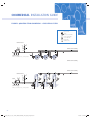
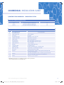
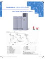
1
COMMERCIAL
COMMERCIAL
INSTALLATION GUIDE
43
0001_QEco_D_C_LC_Owners_Manual_Warranty_A4_Spreads_72pp.indd 43
11/04/12 11:41 AM
COMMERCIAL INSTALLATION GUIDE
CONTENTS
Section 1:
Section 2:
Appliance Details
1a: Commercial Owner’s Details
45
1b: Installer’s Details
45
1c: Service History
45
Installation Details
2a: General Install Requirements
2a1: Location
2a2: Corrosion Protection
2b: Air Flow
2c: Evaporator Drain
2d: Pressure and Temperature Relief (PTR valve)
2e: Expansion Control Valve (ECV)
2f: Cold Water Connection
2g: Pressure Reducing Valve
2h: Caution Regarding Glass Lining of Tank
2i: Suitability for Installation in Frost Areas
2j: Hot Water Connection
2k: Tempering Valves
2l: Electrical Connection
2l1: Safety Notes
2m: Refrigeration Connections (Split Models Only)
2m1: Refrigeration Tube Sizes
2n: Caution Regarding Drilling the Outer Casing
Section 3:
PAGE
47
47
47
47
47
48
48
48
48
48
48
48
49
49
49
49
49
50
Operating Instructions
3a: Filling the Water Heater
3b: Water Quality
50
50
3c: Caution When Left Operating but Unused
50
Appendix A: Specifications and Dimensions
57
Appendix B: Wiring Diagrams
58
List of Figures:
Figure 1: Installation Diagram (Titan Systems)
51
Figure 2: Installation Diagram
51
Figure 3: Quantum Titan Commercial – Circulating System
Figure 4: Hydronic Connection for 340-17ACW3-134
52
54
Figure 5: Hydronic Connection for 1020-17ACW-134
55
Figure 6: Installation Diagram (Split Systems)
Figure 7: Specifications and Dimensions
56
57
Figure 8: Split Fin Coil Evaporators
58
Figure 9: Wiring Diagram: 150/200-08ACW-134 & 270/340-11AC3-134
58
Figure 10: Wiring Diagram: 150/200-08ASW-134 & 340-17ASW-134 (340-TIH-134)
59
Figure 11: Wiring Diagram: 340-17ACW-134
59
Figure 12: Indicator 340-17ACW-134 / 340-ASW-134
60
Figure 13: Wiring Diagram – W/ Timer: 150/200-08ACW-134 & 270/340-11AC4-134
60
Figure 14: Wiring Diagram – &Timer – 150/200-08ASW-134 & 270/340-11AC4-134
61
44
0001_QEco_D_C_LC_Owners_Manual_Warranty_A4_Spreads_72pp.indd 44
11/04/12 11:41 AM
COMMERCIAL INSTALLATION GUIDE
Section 1: APPLIANCE DETAILS
For future convenience, please fill in the following details and retain with your original invoice.
1A: OWNER’S DETAILS
Surname: ................................................................................................................................................... Given Name(s):
.....................................................................................................................
Address: .............................................................................................................................................................................................................................................................................................................................
Town/Suburb:
...................................................................................................................................................................................................................................................................................................................................
State/Territory: ................................................................................................................................................................................................................................................ Postcode: ……………………………………..
Date of Purchase:
..........................................................................................................................................................................................................................................................................................................................
Purchased from: ..............................................................................................................................................................................................................................................................................................................................
Model: ......................................................................................................................................................... Serial Number: ................................................................................................................................................
Date of Manufacture:
................................................................................................................................................................................................................................................................................................................
(Details on the Data Plate of the water heater)
1B: INSTALLER’S DETAILS
Date of Installation: ....................................................................................................................... Installer’s Name: ...........................................................................................................................................
Address: .....................................................................................................................................................................................................................................................................................................................................................
Licence number:
..............................................................................................................................
Installer’s Signature:
.................................................................................................................................
1C: SERVICE HISTORY
Date of Service: .................................................................................................................................. Serviced By:
.......................................................................................................................................................
Work Carried Out: ............................................................................................................................................................................................................................................................................................................................
Signature of Service Agent: ................................................................................................................................................................................................................................................................................................
Date of Service: ................................................................................................................................. Serviced By: ........................................................................................................................................................
Work Carried Out:
..........................................................................................................................................................................................................................................................................................................................
Signature of Service Agent: ................................................................................................................................................................................................................................................................................................
Date of Service: .................................................................................................................................. Serviced By:
.......................................................................................................................................................
Work Carried Out: ............................................................................................................................................................................................................................................................................................................................
Signature of Service Agent: ................................................................................................................................................................................................................................................................................................
0001_QEco_D_C_LC_Owners_Manual_Warranty_A4_Spreads_72pp.indd 45
45
11/04/12 11:41 AM
COMMERCIAL INSTALLATION GUIDE
Section 2: INSTALLATION DETAILS
Titan System
Titan 1020 System
46
AS2712 LIC.2650
SAI GLOBAL
Titan Split system
AS3498 WMKA2531
SAI GLOBAL
0001_QEco_D_C_LC_Owners_Manual_Warranty_A4_Spreads_72pp.indd 46
11/04/12 11:41 AM
COMMERCIAL INSTALLATION GUIDE
2a: General Install Requirements
This water heater must be installed by a licensed tradesperson, and in accordance with:
1. AS/NZ 3500.4 National Plumbing and Draining Code, Part 4: Hot Water Supply Systems
2. AS/NZ 3500.4.2, National Plumbing and Draining Code, Part 4.2: Hot Water Supply systems – Acceptable Solutions.
3. Other relevant Australian standards, industry or local water supply regulations or codes for mains pressure
storage tanks.
*Installation within NZ must confirm to NZ Building Code G12.
Note: This water heater is not suitable for pool or building heating.
2a1: Location
a. The water heater should be located as close as possible to the most frequently used hot water outlets.
b. Adequate access must be made for service to the heat pump, water thermostat, relief valve and anode.
c. Ensure that the specification label is clearly visible. The front service cover of the heat pump section (on top
of tank) must be accessible from the front of the heater; this MUST NOT face the wall. The fan MUST NOT be
positioned up against a wall (Suggested minimum clearance 500mm *see ref Page 51-54 ).
d. The Titan Compact model has a noise level similar to an air conditioner’s outdoor unit (58dBA @ 1.5 metres);
therefore locating the unit away from office or living areas is recommended (both the owner’s & any neighbor’s).
e. Note: All models are equipped with a sacrificial anode, accessible through the top cover. We suggest
allowing 400mm above the top of the water heater (if possible) for clearance to replace the anode
(Please refer to Commercial Warranty Section Pages 36-37).
f. For single or multiple water heater installs, Quantum recommends that a 650mm x 650mm plinth be included
if installed on a floor subject to wet conditions or outdoors. In single or multiple installations a properly drained
overflow tray should be used where property damage could occur from water spillage. (See AS3500.4 for
further details.)
Note: The warranty does not cover damage due to leakage of the water heater.
2a2: Corrosion Protection
a. Fittings and the shell surface in contact with the water are to be galvanically compatible.
b. Sealants and/or Teflon plumbing tape should be used on potentially galvanically incompatible fittings. This is to
protect against possible electrolytic corrosion between the metals (where moisture penetration could occur due to
incorrectly or poorly sealed fittings).
2b: Air Flow
a. The air source models (Compact and split) extract the required heat from air being drawn through their Fin Coil
Evaporator. This produces cold exhaust air as a by-product. Therefore, good ventilation of the proposed location for
the Compact models or the split models’ separate evaporator is required.
b. The Commercial range therefore is best located externally; however a large area with a minimum of 120 cubic
meters with natural ventilation may also be acceptable. The separate evaporator in the split models could be
located externally or in a large well-ventilated ceiling space or garage. GOOD VENTILATION IS REQUIRED.
2c: Evaporator Drain
a. The evaporator drain on the Titan, Titan Split & Titan 1020 Air units should be drained to a suitable location
(as per AS/NZ 3500.4.2).
b. This can be accomplished with a length of hose or pipe but must not be connected directly to the PTR valve
or expansion valve drain.
This is because during operation, a certain amount of condensate water will flow from the evaporator drain.
If allowed to simply flow out of the outlet, this water may pool below the unit and can cause problems.
0001_QEco_D_C_LC_Owners_Manual_Warranty_A4_Spreads_72pp.indd 47
47
11/04/12 11:41 AM
COMMERCIAL INSTALLATION GUIDE
2d: Pressure and Temperature Relief (PTR) Valve
a. The Pressure and Temperature Relief Valve (see tank data label for rating), which is supplied with
the unit, must be fitted and made accessible so that the release mechanism can be operated and,
if required, the valve replaced.
b. The outlet of the PTR valve must be suitably drained to remove the water discharged during the normal heating
cycle. The valve thread is RP ½”/15mm and must be installed into the top front socket..
Warning: A separate drain line must be run for this relief valve. It is not permitted to couple the drain lines
from the relief valve and evaporator into a single common line. The use of a tundish under the evaporator
drain with this then connected to the drain of the PTR valve is acceptable.
2e: Expansion Control Valve (ECV)
a. Where an Expansion Control Valve is fitted to the cold water supply, the ECV should be rated at150kPa lower than
the Pressure & Temperature Relief valve (PTR).
b. It is a State requirement for SA & QLD a ECV must be fitted on the cold water supply line between the non-return
valve and the water heater.
2f: Cold Water Connection
a. An approved isolating valve or approved non-return valve and union must be fitted between the supply main and
the RP ¾”/20mm socket in the water heater.
b. All fittings must be approved by the relevant Authority.
2g: Pressure Limiting Valve
a. This water heater is designed for direct connection to a maximum water supply pressure of 800kPa. Where the
mains pressure can exceed or fluctuate beyond this pressure, a pressure-limiting device (complying with AS1357)
must be fitted in the cold-water supply line.
b. This device must be installed after the isolating valve and set at or below 500kPa (or 350kPa if a 850kPa expansion
control valve is fitted).
c. An ECV is fitted when the water supply has a tendency to form scale. The fitting of an ECV is mandatory in WA,
SA and some other areas of Australia as dictated by local regulations.
2h: Caution Regarding Glass Lining of Tank
a. When making the hot and cold water connections to the tank care should be taken not to apply excessive strain
as damage to the tank spigots or glass lining may occur.
2i: Suitability for Installation in Frost Areas
a. The R134a refrigerant used has a boiling point of -26ºC. Therefore, there is no risk of damage to the heat pump
from frost. Performance may be reduced in very low temperatures, but the system will not be damaged.
2j: Hot Water Connection
a. The hot water pipe should be connected to the RP ¾”/20mm socket as shown in the Installation Diagram
(Figures 1 & 2).
b. It is Recommended that all hot and cold water lines be insulated where possible.
c. NOTE: Plugs are supplied with the water heater to plug off the inlet/outlet entries that are not required.
Ensure that adequate sealing is applied to the plugs for a tight, leak proof seal.
48
0001_QEco_D_C_LC_Owners_Manual_Warranty_A4_Spreads_72pp.indd 48
11/04/12 11:41 AM
COMMERCIAL INSTALLATION GUIDE
2k: Tempering Valves
a. The tempering valve should be fitted on the hot water outlet of the Quantum units to reduce
water temperature to the temperature designated in (e.g., 50°C as per the Local plumbing code
and all Federal, State requirements.
b. Quantum recommends the use of high performance valves suitable for “Solar” type water heaters.
2l: Electrical Connections
a. Quantum water heaters are designed for single-phase 220/240V 50Hz A/C supply only. All electrical work must
be conducted by a Quantum accredited /certified electrician according to the local regulations and AS3000. When
connecting to a Light/Commercial Titan unit a 15-amp circuit breaker must be installed at the power supply for the
hot water units. The power connection rating for Quantum Domestic water heaters up to 1.1kW is 220-240VAC 50Hz
10A. For ALL Titan Commercial model installations 1.7kW is 220-240VAC 50Hz 15A.
b. A separate circuit breaker must be installed for each unit in multiple installations.
c. It is not recommended to wire the system to an earth leakage circuit breaker. There is lot of moisture present while
in operation and this can lead to nuisance tripping.
d. The connection will require an approved, standard 240V On/Off switch or Junction Box in close proximity to the
heater. The unit should be connected to Standard Commercial tariff. Off Peak connection is NOT recommended for
Commercial Quantum heat pump units.
e. The fitted power cord is not to be removed; this cord should be connected with the building wiring in an On/
Off switch enclosure or Junction Box. Faulty wiring WILL void the warranty if damage has been sustained to the
compressor or heat pump from such faulty or sub-standard wiring. *Please note that your Quantum Heat Pump
is now fitted with a Digital Timer. (Not all models). For further information please contact the Quantum
Service Call Centre on 1800 644 705.
2l1: Safety Notes
Note.1: This water heater is fitted with thermostat and over-temperature energy cut-out (both incorporated into
the digital controller). Under no circumstances should the water heater be operated without both of these devices
being in the circuit. Only a qualified electrician or a Quantum Technician or accredited Service Agent should carry out
replacement.
Note.2: If the supply cord is damaged, a Quantum Service Technician or its accredited Service agent /qualified
Electrician must replace it, in order to avoid hazard.
Caution: The water heater must be filled with water before turning on the electricity
2m: Refrigeration Connections (Split Models Only)
a. Refrigeration pipe work is highly specialised and should only be completed by a licensed refrigeration mechanic.
b. Maximum refrigeration pipe length from the tank connections to the evaporator is 8m.
c. If the evaporator is mounted below the tank connection point, then a suitable oil trap needs to be installed on the
suction line between the evaporator and the heat pump.
2m1: Refrigeration tube sizes
COPPER TUBE SIZE – OUTLET
QUANTUM MODEL
COPPER TUBE SIZE – INLET
COPPER TUBE SIZE – OUTLET
150/200-08ASW-134
5/16 Inch (8.0mm)
3/8 Inch (9.5mm)
5/16 Inch (8.0mm)
270/340-11AS4-134
5/16 Inch (8.0mm)
1/2 Inch (12.7mm)
3/8 Inch (9.5mm)
340-17ASW-134
3/8 Inch (9.5mm)
5/8 Inch (16.0mm)
1/2 Inch (12.7mm)
*When the evaporator is below tank level on the Titan model, use a 1/2 Inch (12.7mm) outlet tube.
0001_QEco_D_C_LC_Owners_Manual_Warranty_A4_Spreads_72pp.indd 49
(if evaporator below tank level)
49
11/04/12 11:41 AM
COMMERCIAL INSTALLATION GUIDE
2n: Caution Regarding Drilling the Outer Casing
This is extremely important and MUST be adhered to without exception!
DO NOT DRILL ANY HOLES IN OUTER METAL CASING
DRILLING OF ANY HOLES WILL VOID WARRANTY
Section 3: OPERATING INSTRUCTIONS
3a: Filling the Water Heater
Open all hot water taps. Open isolating valve at the cold-water inlet and allow the water heater to fill until water flows
through the system. Close each hot water tap after the air is expelled from its line.
3b: Water Quality
Your Quantum water heater has been manufactured to suit the water conditions of most Australian and New Zealand
metropolitan supplies. Harsh water supplies can have a detrimental effect on the water heater and its life expectancy.
If you are unsure about your water quality you can obtain information from your local water supply authority.
By using the correct anode, this water heater can be used in areas where the Total Dissolved Solids (TDS) content of
the water supply is up to 2500 mg/L.
In areas where the TDS exceeds 750mg/L it is possible that the magnesium alloy anode (supplied in the heater) may
become over reactive. To alleviate this, the magnesium alloy anode should be checked more regularly, and replaced if
necessary. More information is given in the Commercial Warranty Manual Section on Pages 36-37.
3c: Caution When Left Operating but Unused
If the water heater is left in an operating condition, but unused for two weeks or more, hydrogen gas (highly
flammable) may accumulate on top of the water cylinder. To dissipate this gas safely, it is recommended that:
t "
IPUUBQJTUPCFUVSOFEPOGPSTFWFSBMNJOVUFTBUBTJOLCBTJOPSCBUICVUOPUBEJTIXBTIFSDMPUIFTXBTIFSPS
other appliance.
t %VSJOHUIJTQSPDFEVSFUIFSFNVTUCFOPTNPLJOHPQFOGMBNFPSBOZPUIFSFMFDUSJDBMBQQMJBODFPQFSBUJOHOFBSCZ
t *GIZESPHFOHBTJTEJTDIBSHFEUISPVHIUIFUBQJUXJMMQSPCBCMZNBLFBOVOVTVBMTPVOETJNJMBSUPBJSFTDBQJOH
50
*Refer to www.quantumenergy.com.au for additional information.
0001_QEco_D_C_LC_Owners_Manual_Warranty_A4_Spreads_72pp.indd 50
11/04/12 11:41 AM
COMMERCIAL INSTALLATION GUIDE
SINGLE TITAN INSTALL DIAGRAM:
FIGURE 1: BASIC TANK LAYOUT WITH RECOMMENDED VALVES (EXCEPT TEMPERING)
FIGURE 2: INSTALLATION DIAGRAM
Suggested Distance
from any Wall
500mm
Cool Air Discharge
Ambient Air Flow
Tank Orientation Diagram for Titan Compact Units (Except Split Systems)
51
0001_QEco_D_C_LC_Owners_Manual_Warranty_A4_Spreads_72pp.indd 51
11/04/12 11:41 AM
COMMERCIAL INSTALLATION GUIDE
FIGURE 3: QUANTUM TITAN COMMERCIAL – CIRCULATING SYSTEM
Legend
Expansion Valve
Tundish
Check / Non-Return Valve
Pressure Limiting Valve
1/4 Turn Ball Valve
Isolation Valve
Circulating Pump
Hot Water Return
5
11
4
2
Hot Water Flow to Building
5
TD
6
6
8
6
5
1
2
3
Cold Water Supply
Valves as per Australia / State / Territory standard
7
7
TANK 1
7
TANK 2
TANK 3
Hot Water Flow to Building
6
6
10
6
10
TANK 1
10
TANK 2
TANK 3
Hot Water Flow to Building
Hot Water Return
6
5
To Drain
4
6
7
2
10
9
TD
Valves as per Australia / State / Territory standard
5
7
10
5
5
1
2
3
Cold Water Supply
6
8
11
9
5
7
5
9
5
7
To Drain
10
5
7
To Drain
To Drain
52
0001_QEco_D_C_LC_Owners_Manual_Warranty_A4_Spreads_72pp.indd 52
11/04/12 11:41 AM
COMMERCIAL INSTALLATION GUIDE
QUANTUM TITAN COMMERCIAL – CIRCULATING SYSTEM
Header Sizes for Multiple Quantum Heat Pumps
Number Of Heaters In Bank
Nominal Size Of Headers
3 to 5
One pipe size larger than branch pipes
Minimum Size Of Headers DN
25
6 to 10
Two pipe size larger than branch pipes
32
11 to 15
Three pipe size larger than branch pipes
40
Manifolded Titans Specifications
Ref No.
Description
Specifications
A
Header/Manifold Cold*
B
Header/Manifold Hot*
1
Isolation Valve Cold**
¼ Turn - Ball Valve
2
Check Valve**
Check Valve
3
Pressure limiting Valve
Adjustable Pressure Relief Valve
4
Cold Water Relief Valve
DN20 850kPa to local codes
5
Isolation valves
DN20 1/4 turn ball valves
6
Hot water branch
DN20 equal length encapsulated copper
AS PER ABOVE TABLE
7
Cold water branch
DN20 equal length encapsulated copper
8
Isolation Valve Hot**
¼ Turn – Ball Valve
9
PTR Valve
1000kpa (supplied with tank)
10
Condensation Drain
To tundish and drain
11
Circulating Pump
Hot water recirculating pump – Circulating pump
Distance from wall
500mm where air is exhausted toward wall
12
Tank centres
900mm (200mm between tanks)
Insulation
Min 13mm Armflex or similar to all hot pipework, and all pipework
on flow and returns systems
Electrical
15A isolating switch within 1 metre of each unit. Separate 15A circuit
breaker per unit. NOTE 3 pin plugs are not recommended
Fan box
†
Applicable to page 56 diagram
* Manifold/header sizes to be calculated according to flow requirements.
** Same nominal diameter as manifold/header.
*Refer to www.quantumenergy.com.au for additional information.
0001_QEco_D_C_LC_Owners_Manual_Warranty_A4_Spreads_72pp.indd 53
53
11/04/12 11:41 AM
COMMERCIAL INSTALLATION GUIDE
FIGURE 4: HYDRONIC CONNECTION FOR 340-17ACW3-134
*Suggested Minimum
Distance of 200mm
between Tanks
*Suggested Distance
from any Wall
500mm
Cool Air Discharge
Ambient Air Flow
Red “Alert” Lamp to face
out from wall
When installing a single Titan Compact unit the intake fan should always point out from, or along the wall.
If the cold air discharge fan is facing towards a wall, the suggested distance between the unit and the wall is *500mm.
Multiple installations of Titan Compacts must be plumbed in using an “Equal Flow Manifold System” failure to do so
may void warranty.
When installing multiple Titan Compact units, the fan should never face towards the adjacent unit.
(Cold discharge fan to ambient air intake fan) this would reduce the efficiency of the units.
*The space between multiple units should be a minimum of 200mm for air flow, where possible 500mm is suggested
for the convenience of service. See schematic above.
*If the distance is less than 500mm off a wall the use of “Baffle” panels may be necessary. Baffles are positioned along
the top and between the units to assist the cold air discharge downwards to prevent cold air bouncing back into the
ambient air intake.
If you have any questions in regards to installation please contact your local Quantum office or call 1800 644 705
for assistance.
54
0001_QEco_D_C_LC_Owners_Manual_Warranty_A4_Spreads_72pp.indd 54
11/04/12 11:41 AM
COMMERCIAL INSTALLATION GUIDE
FIGURE 5: HYDRONIC CONNECTION FOR 1020-17ACW-134
AS2712 LIC.2650
SAI GLOBAL
AS3498 WMKA2531
SAI GLOBAL
55
0001_QEco_D_C_LC_Owners_Manual_Warranty_A4_Spreads_72pp.indd 55
11/04/12 11:41 AM
COMMERCIAL INSTALLATION GUIDE
FIGURE 6: TITAN SPLIT SYSTEM
(MODEL 340TIH-134 SHOWN)
Other Split System Models available:
Quantum recommends that the fan box should not extend more than 8m from the tank.
150-08ASW-134, 200-08ASW-134, 270-11AS4-134, 340-11AS4-134, 340-17ASW-134 – (340Ti H-134
Hot Water Return
5
11
4
2
Hot Water Flow to Building
5
TD
6
6
8
6
5
1
2
3
Cold Water Supply
Valves as per Australia / State / Territory standard
7
7
TANK 1
7
TANK 2
TANK 3
Hot Water Flow to Building
Hot Water Return
6
5
6
6
8
11
To Drain
4
2
10
9
TD
1
2
3
Cold Water Supply
Valves as per Australia / State / Territory standard
10
5
5
9
5
9
5
7
5
7
To Drain
12†
10
5
7
To Drain
12†
To Drain
5
Note: The pipes connected to
the water heater’s cold water
and hot water connections are
not to be a type that is flexible/
soft. All refrigerant piping needs
to be installed by a licensed
refrigeration mechanic.
†
12†
Please refer to table on page 53.
Ref No 12.
56
0001_QEco_D_C_LC_Owners_Manual_Warranty_A4_Spreads_72pp.indd 56
11/04/12 11:41 AM
COMMERCIAL INSTALLATION GUIDE
Appendix A: SPECIFICATIONS AND DIMENSIONS
FIGURE 7: SPECIFICATIONS AND DIMENSIONS
C
C
C
A
A
A
B
B
B
70mm
MODEL NUMBER
70mm
70mm
MASS
(EMPTY (KG)
MASS
(FULL) (KG)
R134a
Charge (gm)
100
250
1650
150-08ACW-134
200-08ACW-134
115
315
1650
270-11AC3/4-134
135
405
1850
340-11AC3/4-134
170
510
1850
340-17ACW-134
190
535
2650
150-08ASW-134
90
240
1650
DIMENSIONS(MM)
A
B
C
1620
975
540
1950
0
0
1900
2200
0
0
2240
1545
0
NOMINAL
CAPACITY (LT)
660
125
1305
540
660
11905
650
0
14905
650
0
0 986
0 986
1490
650
1660
975
540
660
0
540
0
650
0
0
660
0
986
0
250
315
315
125
315
125
175
105
305
1650
270-11AS4-134
120
390
1850
1765
1190
340-11AS4-134
155
495
1850
2060
1490
650
986
315
165
505
2650
2110
1490
650
1660
315
(
1305
0
175
125
175
200-08ASW-134
340-17ASW-134
340TIH-134
1875
0
POWER
INPUT (W)
175
250
)
MODEL
EVAPORATOR DIMENSIONS
EVAPORATOR WEIGHT
EVAPORATOR FAN
NOISE @1.5 MTR
AIR FLOW
LITRES/SECOND(W)
150/200-08ACW-134
Internal
N/A
50dBA
415
270/340-11AC3/4-134
Internal
N/A
52dBA /48dBA
550
340-17ACW-134
Internal
N/A
58dBA
800
150/200-08ASW-134
430× 380× 120
15kg
48dBA
460
270/340-11AS4-134
480× 430× 120
18kg
50dBA
600
340-17ASW-134
655× 580× 380mm
35kg
58dBA
880
57
0001_QEco_D_C_LC_Owners_Manual_Warranty_A4_Spreads_72pp.indd 57
11/04/12 11:41 AM
COMMERCIAL INSTALLATION GUIDE
FIGURE 8: SPLIT EVAPORATOR – FINNED COIL
D
B
Air Flow
A
Refrigeration
Connection
C
3/8 ”
Discharge
Line
Power Cable
5/8”
Suction
Line
100
50
110
40
150
A qualified refrigeration technician must install the Split Finned
model. Whilst the plumbing and electrical work is the same as
the Compact, this unit also requires on site refrigeration work.
(
)
Appendix B: WIRING DIAGRAMS
FIGURE 9: WIRING DIAGRAM: 150/200-08ACW-134 & 270/340-11AC3-134
58
0001_QEco_D_C_LC_Owners_Manual_Warranty_A4_Spreads_72pp.indd 58
11/04/12 11:41 AM
COMMERCIAL INSTALLATION GUIDE
FIGURE 10: WIRING DIAGRAM: 150/200-08ASW-134
& 340-17ASW-134 (340-TIH-134):
FIGURE 11: WIRING DIAGRAM: 340-17ACW-134
59
0001_QEco_D_C_LC_Owners_Manual_Warranty_A4_Spreads_72pp.indd 59
11/04/12 11:41 AM
COMMERCIAL INSTALLATION GUIDE
FIGURE 12: INDICATOR 340-17ACW-134 / 340-ASW-134
Indicator light
FIGURE 13: WIRING DIAGRAM – WITH TIMER: 150/200-08ACW-134 & 270/340-11AC4-134
60
0001_QEco_D_C_LC_Owners_Manual_Warranty_A4_Spreads_72pp.indd 60
11/04/12 11:41 AM
COMMERCIAL INSTALLATION GUIDE
FIGURE 14: WIRING DIAGRAM – WITH TIMER –
150/200-08ASW-134 & 270/340-11AS4-134
AS2712 LIC.2650
SAI GLOBAL
AS3498 WMKA2531
SAI GLOBAL
0001_QEco_D_C_LC_Owners_Manual_Warranty_A4_Spreads_72pp.indd 61
61
11/04/12 11:41 AM