1
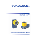
MATRIX 400™ REFERENCE MANUAL
1
Required Accessories
The following table shows the correct lens/illuminator combinations to be used for Matrix
400™ imager assembly.
Lenses
Internal Illuminators
93ACC1793
LNS-1006
6 mm C-Mount Lens
(only for Matrix 400 600-0x0 models)
93A401020
93A401022
LT-002
LT-004
Red Wide Angle
White Wide Angle
93ACC1794
LNS-1109
9 mm C-Mount Lens
93ACC1795
LNS-1112
12.5 mm C-Mount Lens
93ACC1796
LNS-1116
16 mm C-Mount Lens
93ACC1797
LNS-1125
25 mm C-Mount Lens
93ACC1798
93ACC1799
LNS-1135
LNS-1150
35 mm C-Mount Lens
50 mm C-Mount Lens
93A401020
93A401022
93A401020
93A401022
93A401019
93A401021
93A401019
93A401021
93A401024
93A401024
LT-002
LT-004
LT-002
LT-004
LT-001
LT-003
LT-001
LT-003
LT-006
LT-006
Red Wide Angle
White Wide Angle
Red Wide Angle
White Wide Angle
Red Narrow Angle
White Narrow Angle
Red Narrow Angle
White Narrow Angle
Red Super Narrow Angle
Red Super Narrow Angle
STEP 2 – CONNECT THE SYSTEM
To connect the system in a Stand Alone configuration, you need the hardware indicated in
Figure 2. In this layout the data is transmitted to the Host on the main serial interface. Data
can also be transmitted on the RS232 auxiliary interface independently from the main
interface selection.
When One Shot or Phase Mode Operating mode is used, the reader is activated by an
External Trigger (photoelectric sensor) when the object enters its reading zone.
PG 6000
CBX
Main Interface
CAB-MS01
Matrix 400™
Host
P.S.*
I/O, AUX
* External Trigger or Presence Sensor
(for One Shot or Phase Mode)
Figure 2 – Matrix 400™ in Stand Alone Layout
2