1
Spektrum
Graphics
Adapter
Color graphics for all
Atari-ST(E)/TT-Systems
User's Manual
English translation by Marcel Schön, Switzerland, 2013
Table of Contents
Hardware Installation.................................................................................................................................3
Installation in a Mega STE....................................................................................................................3
Installation in a TT................................................................................................................................4
Installation in a Mega ST......................................................................................................................4
Software Installation..................................................................................................................................5
Installation with only one floppy disc drive..........................................................................................5
Using the installation program..............................................................................................................5
Using the help function.........................................................................................................................6
Installation keyboard usage...................................................................................................................7
Functions that can be triggered through the mouse...............................................................................8
Using the Spektrum installation form...................................................................................................9
Testsoftware.........................................................................................................................................11
Choosing a monitor.............................................................................................................................11
Installation of Charly-Image-software................................................................................................12
Using the software...................................................................................................................................13
The Timing conrol panel.....................................................................................................................13
Creating a new timing.........................................................................................................................16
The color control panel........................................................................................................................17
Changing the color palette...................................................................................................................17
Color calibration..................................................................................................................................18
Spektrum for advanced users...................................................................................................................19
Files on the original floppy disk..........................................................................................................19
The SPEKTRUM.INF file...................................................................................................................20
Programming Instructions...................................................................................................................20
Data structures of the Spektrum software...........................................................................................21
Memory structure................................................................................................................................23
Extended Function of Spektrum VDI..................................................................................................24
Connector pin assignment...................................................................................................................24
Technical Specifications......................................................................................................................25
The various different versions.............................................................................................................26
Hardware Installation
Installing the Spektrum graphics card is very easy. Below are the descriptions of how to insert the card
into the various types of computers.
Installation requires only a small screwdriver with a cross slot and a regular screwdriver. Should you
have any doubts about your mechanical skills, we recommend having the card installed by a local
spezialized dealer. Especially if your computer is a Mega ST, the sometimes required resynchronization of the power supply should be done by an expert.
Naturally, the computer must be switched off before performing any hardware installation work. Please
pull the power plug first!
Installation in a Mega STE
For the installation in a Mega STE, the protection cover of the VME bus slot must be removed first.
The cover is labeled “VME” and held in place by two screws.
As soon as these screws are loose, the cover can carefully be removed by pulling it backwards. Behind
it is the VME slot with slide-rails to both sides. Slide the card in these rails, horizontally, with the
electronic parts (ICs etc.) upwards.
The VME slot from the side:
wrong
correct
The card should be pushed without excessive force until its side-panel properly aligns with and closes
the computer case. Fix the cards position with the two screws on both sides of the panel.
Installation in a TT
For the installation in a TT, the protection cover of the VME bus slot must be removed first. The cover
is labeled “VME” and held in place by two screws.
As soon as these screws are loose, the cover can carefully be removed by pulling it backwards. There
are two connectors for serial ports attached to this panel; remove them completely, or place them
somewhere else in the TT case. Behind it is the VME slot with slide-rails to both sides. Slide the card in
these rails, horizontally, with the electronic parts (ICs etc.) upwards.
The card should be pushed without excessive force until its side-panel properly aligns with and closes
the computer case. Fix the cards position with the two screws on both sides of the panel.
Installation in a Mega ST
The installation in a Mega ST is more complicated. It is recommended to have a specialist do this,
because doing it yourself may void your warranty.
The details of how to do this can be found in the original, german manual.
Software Installation
When using the Spektrum graphics card, a harddisc (HDD) is recommended as well. This chapter will
explain how you can install the Spektrum software using the installation program. The Spektrum
graphics card can be using with a harddisc drive as well as with a floppy disc drive. But in any case a
special driver software is required for the operating system to be able to use the card.
Installation with only one floppy disc drive
The Spektrum software can also be launched from a floppy disc drive. The included original disk is
pre-installed, so that you can boot the Spektrum software from it.
This requires a standard VGA monitor, more precisely, the TT color monitor PTC 1426.
In case you are using a different monitor without multisync-capacity, an appropriate timing must be
created, or another monitor-timing-file (.INF) be renamed to SPEKTRUM.INF and copied into the
AUTO folder.
Using the installation program
The installation will be considerably easier when using a harddisc drive (or something similar). In that
case, just insert the Spektrum floppy disc into your floppy disc drive and launch the program
INSTA256.PRG, INSTA_HC.PRG, INSTA_HR.PRG or INSTA_TC.PRG, respectively (depending on
the type of your graphics card).
The menu line consists of the following options:
• “SPEKTRUM”: Shows the copyright message of the Spektrum installation and accessories.
• “Datei” (“File”): Shows the following entries
• “Neu” (“New”): Shows a dialog that allows to start the installation; “Install beenden”
(“End installation”): The program exists.
• “Extra”: Shows the following entries
• “Hilfe” (“Help”): Shows the online help.
Using the help function
The help function can be used either with the mouse or the keyboard.
You can click on underlined entries to see more information about the selected word
By clicking on “<<<” you return to the previous word.
An overview of the existing keywords of the “Help”-function can be found in the keyword index
(“Stichwortverzeichnis”).
The “Help” function can also be used by keyboard:
• “Undo”: Shows the help text for the previously selected keyword
• Cursor keys: Scrolls the window content around
• Cursor keys + CTRL: Scrolls the window contents by a half page.
If additional fonts were installed through GDOS, to additional keys can be used:
• “<” and “>”: Switch between the fonts. Only non-proportional fonts will be used.
• “+” and “-”: Changes the font size.
Installation keyboard usage
Menu options can also be triggered through the keyboard. Each keyboard shortcut is listed at the
corresponding menu option.
The “^”-character means that the specified key must be pressed together with the CTRL key.
Menu option “SPEKTRUM”
• CTRL-I: program information
Menu option “Datei” (“File”)
• CTRL-N: New, perform installation
• CTRL-Q: Quit, end program
Menu option “Extra”:
• Help
Other keys:
• “Esc”: Show window contents
• Cursor keys: scroll window contents
• Cursor keys + SHIFT: scroll window contents horizontally
• Cursor keys + CTRS: scroll window contents by a half page
• “Home”: Jump back to the beginnin in the upper left corner of the window
• “+”: Magnifier
• “0”: Normal size
• “-”: Overview
• “*”: Fullscreen size
• CTRL-W: Switch between windows
• CTRL-U: Close window
Alert boxes can also be handled with keyboard shortcuts:
• “1”: Select the first button
• “2”: Select the second button (if available)
• “3”: Select the third button (if available)
• “Undo”: Select “Cancel” button (if available)
A button with a bold border can be selected by pressing the “Return” key.
In dialog windows, an underlined character in a button label signals which key to use to select that
button, e.g. “S” for “Start”.
Another important fact is the type of function that correlates with a certain button, e.g. the key “Undo”
for “Cancel”, the key “Delete” for “Löschen” (“delete”) or the key “Help” for “Hilfe” (“help”).
It is possible that multiple keys may trigger the same function, e.g. cursor keys and “+” or “-” to move
a scrollbar in a window.
Functions that can be triggered through the mouse.
Left mouse button:
• left upper window corner: close window
• upper window border: move window
• right upper window corner: maximize window
• scroll bar: scroll window contents
• lower right window corner: change window size
Right mouse button:
• in a window: move window contents
• lower right window corner: change window size
• window border: move window
By keeping the right mouse button pressed, even inactive windows can be used. When using only the
left mouse button, only the top window will be used, or a lower window will be brought to top
(foreground).
Using the Spektrum installation form
The installation program copies all the required files of the Spektrum software to the correct locations
on the harddisc drive. To start the installation, select the menu option “Neu” (“new”) under the main
menu option “Datei” (“file”).
This will trigger a form with the following setup options:
•
•
•
•
“Monitor-Typ” (monitor type): Name of the INF-file which will be installed afterwards under
the name “SPEKTRUM.INF” in the “AUTO”-folder.
“Boot-Laufwerk” (boot drive): The harddisk partition which contains the AUTO-folder and the
accessories, and where the ASSIGN.SYS file is located. Usually, drive “C” is the boot drive.
“GEMSYS-Pfad” (GEMSYS path): The location of the directory which contains the fonts and
VDI drivers.
“CPX-Pfad” (CPX path): The directory where the control panel of Atari, “XCONTROL.ACC”,
loads its CPX-modules from. Usually, this folder should be named “C:\CPX”.
Normally it is not necessary to change any settings here except for selecting the monitor type, because
the installation program detects the settings automatically, or (if the directory locations cannot be
determined) sets default values, which will then be used during the installation.
The installation starts as soon as the “Start”-button on the installation form is selected.
Firstly, the GEMSYS-folder will be created if necessary, and all Spektrum VDI drivers will be copied
into that folder.
For the Spektrum-1 card it's the file “SPEK_256.SYS” for the 256-color mode. For the Spektrum-HC
card, also the file “SPEK_HC.SYS” for the HiColor-mode is copied.
For the Spektrum-TC card the file “SPEK_TC.SYS” is copied as well for the TrueColor mode.
Furthermore, the file “VDI.SYS” is copied into this folder as well.
Secondly, the “AUTO”-folder will be created if necessary, and the files
•
•
•
•
•
•
SPEKTRUM.PAL,
SPEKTRUM.INF,
SPEKTRUM.PRG,
SYSTEM08.FNT,
SYSTEM09.FNT and
SYSTEM10.FNT
will by copied into that folder.
Thirdly, the folder “CPX” will be created if necessary, and the control panel modules
“SPEKTRUM.CPX” and “TIMING.CPX” will be copied into it.
Afterwards the file “ASSIGN.SYS” will be created in the root level of the boot partition.
Finally, the GDOS “AMCGDOS.PRG” will be copied into the “AUTO” folder and the control panel
“XCONTROL.ACC” in the root level of the boot partition.
This concludes the installation.
If the installation finds files what would be overwritten during the installation process, an alert dialog
box appears with three options:
•
•
•
“Ersetzen” (“replace”): The new file will be created, and the old file will be backed up into a
sub-directory name “OLD”.
“Weiter” (“continue”): The new file will not be created, the old file remains unchanged. There
is one exception, the “ASSIGN.SYS” file; if “Weiter” is selected for this file, the existing file
will not b replaced, but the contents of the new file will be merged into it, so that the previously
installed printer drivers and fonts remain unchanged.
“Abbruch” (“cancel”): The installation will be cancelled. ATTENTION: An incomplete
installation can result in a non-bootable system. So, one should either perform the complete
installation process again, or restore the previous system state, using the files that were backed
up into the “OLD” subdirectories.
Testsoftware
For the Spektrum graphics cards, the test software is not a separate application; the test functionality is
integrated into the installation program.
Under the menu option “Extra” is, besides the “Hilfe” (“help”) option, an option for the card testing
functionality. Details about it can be found in the “LIESMICH.TXT”-File (“readme”) on your original
floppy disk.
Choosing a monitor
The following monitors are available (depending on the version of the software, some of the monitors
could be missing, or additional ones could be available). Please check the “LIESMICH.TXT”-file
(“readme”) on your original floppy disk; this file also contains a mapping from monitor type to
filename.
•
•
•
•
•
•
•
•
•
•
•
•
•
•
•
•
•
•
Standard VGA
Acer 7015
Miro C1766
Miro C2166
Atari PTC 1426
Atari SC1224
Eizo 9070
Eizo 660
Eizo 6500
Eizo 9500
NEC 3FG
NEC 4FG
NEC 5FG
NEC 6FG
Sampo 1466D
Sampo 1566D
Sampo 1766D
Samsung Syncmaster 3
Should your monitor not be among those mentioned here (i.e. not among those on your floppy disk),
you may create a matching file yourself.
Installation of Charly-Image-software
Each Spektrum graphics card comes with a demo-version of the software “CharlyImage”. This sofware
allows to demonstrate the capabilities of the graphics card. By using the original floppy disk, you may
simple launch the software; it is completely installed ready-to-use on the floppy disk.
When using a harddisc drive, the contents of the entire floppy disk can just be copied into any folder on
the harddisc.
It is also possible to start the “CharlyImage” tool with some parameters. This means that you can
register this application for certain file types, such as “*TIF”.
You may images in all common file formats display on the cards with the maximum number of colors.
The software supports the following formats:
•
•
•
•
•
•
•
•
•
•
•
•
•
•
•
•
•
TIFF 5.0
Windows BMP
GIF
Sun-Rasterfile
GEM-Image
STAD
Degas PI1/PI3
JPEG
Spectrum 512
TINY
raw monochrome data
raw RGB data
Targa
VORT-PIX
PPM-/PGM
ICM
and others depending on the program version...
Using the software
Most GUI elements of the Spektrum software are implemented as CPX accessories. They will be
installed by the Spektrum installation software.
The Timing conrol panel
With the help of the “Timing” control panel you can use almost any monitor with the Spektrum
graphics card. It allows to freely change many parameters of the video signal created by the card. This
way, even fixed-frequency monitors can be used with the Spektrum card.
Should you have a very exotic monitor or simply want to use a very special resolution or picture
frequency, the timing-editor for the Spektrum card can be used. It is a CPX accessory and can be
invoked at any time.
Within the timing control panel there are four work pages. Use the pop-up menu in the upper left corner
to switch between these work pages. It is also possible to switch between the four pages using the F1 to
F4 keys.
On the first page, an arbitrary name can be given for every setting. If you don't want to think of a name
for yourself, it's also possible to just click on the name area with the mouse, and the program will offer
a name created based on the selected resolution parameters.
The arrow symbols can be used to switch between the predefined resolutions. The currently preselected
resolution will be displayed in blue color on color monitors.
The software always manages a list of video timings, and allows to add and remove entries in this list
by clicking on the buttons “Hinzufügen” (“add”) or “Entfernen” (“remove”) below the name area:
Auflösung = resolution
Hinzufügen = add
Entfernen = remove
Pixeltakt = pixel cycles / speed
H-Frequenz: horizonal frequency
V-Frequenz: vertical frequency
Farbmodus: color mode
Sichern = save
OK = confirm
Abbruch = cancel
Below these buttons, the selected horizontal and vertical frequency are displayed, as well as their
respective allowed maximum values (as accepted by the monitor). The buttons “X/2” and “Y/2” enable
special effects. With “X/2”, every pixel doubles in width, i.e. the card works with the pixel frequency
cut in half. With “Y/2”, every screen line will double; this is useful for zoom functions.
Two other pop-ups allow to switch between different color modes and pixel frequencies. Depending on
the type of card, the following options are available:
• 256 colors (palette colors)
• HiColor (65536 colors)
• HiColor 2 (32768 colors)
• TrueColor (16.777.216 colors)
• HiRes (16 colors)
• Monochrom (2 colors)
•
The available frequencies also vary from card to card. The HR- and the TC-card offer slightly higher
maximum frequencies.
The second page shows the resolution parameters. Here, all the usually changed settings can be
configured.
Bildgrösse = picture size
Breite = width
Höhe = height
Virtuell = virtual
Total = total
Sichtbar = visible
Bildlage = picture position
Start = start
Länge = length
Sichern = save
OK = confirm
Abbruch = cancel
In the upper area, the virtual resolution for horizontal and vertical directions can be configured
(“Virtuell”). Invalid values will be marked with red color.
Below, the resolution can be configured on which the timing is based (“Total”). This is the time that
includes showing the video picture, including the sync- and blank-signal.
Below that, the visible resolution (“Sichtbar”) is configured for both directions (horizontally and
vertically).
The picture position (“Bildlage”) is controlled by the sync- and blank-signal. Also, the length of these
impulses can be adjusted. Some monitors can handle short impulses, other monitors require longer
impulses. With shorter impulses, the image position can be changed in larger areas. If the impulses are
too short, it is possible that the picture cannot be synchronized correctly.
To the right of these settings, the pixel frequency can be selected. The horizonal and vertical
frequencies are a result of all these parameters and will be calculated by the control panel and displayed
below the pixel frequency.
With the “Test”-button you can test the newly configured settings. There are four different options:
•
•
•
•
“Desk” - The desktop will be displayed with the new settings, as long as the left mouse button
is kept pressed.
“Bild” (“picture”) - Like “Desk”, but a test picture instead of the desktop will be displayed.
“Set!” - The parameters will be accepted and activated, and will remain active until the next
reset / reboot.
“Demo” - Like “Bild”, only that a little animation will be started that also provides an
impression of the performance of the graphics card.
Should you accidentally set a resolution that the monitor cannot synchronize with the “Set!” option,
press F10 to revert to the old settings.
As long as the “Test”-button is kept pressed, the right mouse button allows to ajust the image position
(“Bildlage). With the plus-/minus symbols, the polarity of the sync-signals can be reversed. VGA
monitors use this to detect the video mode and change some of the video settings for the picture size on
a CRT tube.
“OK” accepts the settings, but only with “Sichern” (“save”) will they also be used when the system is
rebooted again. “Sichern” will copy the required VDI driver to VDI.SYS, and adapt the
SPEKTRUM.INF file accordingly.
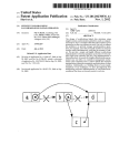
The third page is a special page for the horizontal timing. Here, all parameters of the contoller can be
freely configured.
Gesamt = total
Sichtbar = visible
Sichern = save
OK = confirm
Abbruch = cancel
In the lower area are graphical representations of the blank- and sync-area. The configured values will
not be validated at all (beware of frying your monitor).
The fourth page is also a special page – for the vertical timing. Here, all parameters of the contoller can
be freely configured.
Gesamt = total
Sichtbar = visible
Sichern = save
OK = confirm
Abbruch = cancel
In the lower area are graphical representations of the blank- and sync-area. The configured values will
not be validated at all (beware of frying your monitor).
Creating a new timing
To create a new timing, follow these steps:
•
•
•
•
•
Configure the visible resolution that you want – the monitor should be capable of displaying it.
Then select a color mode. Afterwards, a matching pixel frequency must be chosen. In the
HiColor mode, it must be twice as high, and in the TrueColor mode three times as high as the
speed of the pixel rendering. Therefore, when you use the same videotiming with 256 colors
and with HiColor mode, you will get only half the horizontal resolution in the HiColor mode,
because rendering a pixel requires two pixel cycles. The pixels would then be twice as wide.
The horizontal frequency must have a value supported by the monitor and corresponding to the
pixel frequency. This can be done by changing the horizontal “Total” value or the vertical
“Total” value. The vertical “Total” value must also be set to a value accepted by the monitor.
In the meantime, the resolution can be tested with the “Test”-button. This works with only one
or with two connected monitors. In the single-monitor setup, the old video parameters will be
saved.
Please note: With standard VGA monitors, the polarity of the sync signals is important!
The color control panel
The colors of the Spektrum card can be freely adjusted in all modes. There is an accessory that can be
invoked at any time to do this. The color control-panel is a CPX-accessory, so it consumes memory
only when it is actually used. Details about its installation can be found in the instructions for your
control-panel.
Changing the color palette
The control-panel provides two pages for adjusting the colors. They can be selected with the F1 or F2
keys or with the mouse, through a pop-up menu.
Farben = colors
Laden = load
Sichern = save
OK = confirm
Abbruch = cancel
On the preselected page 1, all colors are listed in the area to the right. Depending on the mode, the
palette contains up to 256 colors. The scrollbar to the right allows to select a certain entry. This can also
be done by clicking on a color entry with the mouse. The currently selected color is shown in the upper
right corner in a somewhat larger box.
The three sliders on the left side allow to define the selected color. With them, the red-, green- and blue
value of the color can be adjusted independently.
In the 256 color mode, changes will become visible immediately. In the HiColor and TrueColor mode,
the changes will only be performed in the control-panel first. Only once the control-panel is closed by
clicking on the “OK” button will any program that is launched afterwards use the new palette. This
way, it is possible to use custom color palettes for separate applications under Multi-GEM, Multi-TOS
or MAGIX.
“Laden” (“load”) and “Sichern” (“save”) allow to load and save entire color palettes.
With the functions on the second page, color gradients can be created:
Verlauf = gradient
Start = begin
Grau = gray
Reset = reset
Laden = load
Sichern = save
OK = confirm
Abbruch = cancel
This allows to create a linear gradient between two positions in the color palette. To do this, one color
entry (the “Start” color) must be selected first and the button “Start” must be clicked. This button's
label will then switch to “Ende” (“end”). Now the target color must be selected, and the “Ende” button
must be clicked. This will create the gradient between the “Start” and the “Ende” color.
With “Grau” (“gray”) or “Farbe” (“color”), the color palette can be converted to shades of gray or vice
versa. The behaviour is similar to that of the TT control-panel.
“Reset” sets the colors back to the values of the control-panel.
Color calibration
This is an additional feature which is available with some versions of the TrueColor (TC) or HiColor
(HC) card. Details can be found in the LIESMICH.TXT (read-me) file on the floppy disk.
The function allows to define a separate gamma curve for each color channel, to compensate for color
divergence in picture displayed by the monitor. This is useful for truecolor image processing. Regular
color monitors don't have a linear correlation between the brightness of the phosphor and the voltage of
the video signal, which can be compensated this way. Depending on the type of card, there is a third
page in the color control-panel which allows to define the gamma curve. The curve can be defined
separately for red, green and blue.
Spektrum for advanced users
Example for an ASSIGN.SYS file
The ASSIGN.SYS-file used by GDOS has the following structure (TT version):
PATH = A:\GEMSYS /* The folder with the fonts */
01 VDI.SYS
COUR10.FNT
/* Optional: fonts */
02 VDI.SYS
03 VDI.SYS
04 VDI.SYS
05 VDI.SYS
/* All screen drivers... */
COUR10.FNT
/* Another font... */
06 VDI.SYS
07 VDI.SYS
08 VDI.SYS
Files on the original floppy disk
Start program:
\AUTO\SPEKTRUM.PRG: Switches the card on after boot
\AUTO\SPEKTRUM.INF: Info-file for the resolution / timing settings
\AUTO\SPEKTRUM.PAL: Color palette file
VDI-Driver:
\GEMSYS\VDI.SYS: active driver
\GEMSYS\SPEK_256.SYS: driver for 256 colors
\GEMSYS\SPEK_HC.SYS: driver for 32768 colors (HiColor)
\GEMSYS\SPEK_TC.SYS: driver for 16.777.216 colors (TrueColor)
System fonts for the VDI driver:
\AUTO\SYSTEM08.FNT: 6x6 system font
\AUTO\SYSTEM09.FNT: 8x8 system font
\AUTO\SYSTEM10.FNT: 8x16 system font
GDOS:
\AUTO\AMCGDOS.PRG: The GDOS loads the VDI driver listed in the ASSIGN.SYS file.
Additional programs:
\XCONTROL.ACC: The Atari control-panel
\CPX\SPEKTRUM.CPX: CPX module for configuring the colors in the control-panel
\CPX\TIMING.CPX: The change the SPEKTRUM.INF file, to switch to other resolutions or to
generate new resolutions for new monitors.
The SPEKTRUM.INF file
This file contains the timing information for the timing control-panel. The structure of the file can
change slightly between versions. For this reason, it is recommended only to change the documented
values by hand.
The first two lines define the maximum frequencies for the horizontal frequency in Kilo-Hertz and for
the vertical frequency in Hertz.
The value in the third line is an ID for a certain IC (microchip) on the graphics card.
The currently selected resolution is marked by a “*” character.
The file looks like this:
65.000
120.000
30
*,”640x400 256 68 Hz”,0,5,100,79,79,20,88,11,520,399,400,119,455,4,0,0,0,0,0,640,400
“640x480 High 100 Hz”,2,15,190,159,159,30,167,12,525,479,488,28,496,4,0,0,0,0,0,640,480
Programming Instructions
This chapter is meant for programmers. It should help to create “clean” applications that run properly
on graphics cards. This is absolutely possible, since the interface to the graphics card is standardized:
The VDI (the so-called virtual device interface). To ensure that software will also run on future, not yet
available graphics gards, only GEM-functions must be used for all graphical in- and output operations.
Never should the screen memory or any registers on the card be accessed directly! For this reason,
this documentation does not discuss details of the registers of the graphics card.
To ensure that your custom software runs in all resolutions and color modes, you should only use VDI
and AES functions for graphical operations. And keep in mind that the resolution and the memory
requirements for a certain picture size may vary.
Don't use BIOS or XBIOS functions for graphical output operations. All graphical outputs must be
clipped to the current screen size.
Data structures of the Spektrum software
The following data structures are created:
typedef struct {
long cookie;
long product;
int version;
int x,y,w,h;
}
INFOVSCR;
/* VSCR */
/* product name */
/* visible window */
typedefstruct {
int palette[256][3];
}
PALETTE;
typedef struct {
long
magic;
/* 'VINF' */
long
version;
/* 0x0100 */
long
factory;
/* 'JWME' */
long
product;
/* 'SPEK' */
long
product_version;
/* '1 ', '1 HC', '1 TC' */
long
video_base;
/* address of 1st pixel in video memory */
int
width;
/* number of pixels */
int
height;
/* number of pixels */
int
line_offset;
/* number of pixels from line to line */
int
bits_per_pixel;
int
bits_per_pal; /* number of bits in palette-RAM (6 or 8) /
PALETTE
pal;
void
(*mouse_pos)(int x,int y,int button);
/* positions the screen so that the mouse pointer is
most likely in the visible area */
void
(*set_root)(int *redraw_pxy);
/* Function which is called every time the desktop
background should be redrawn. 'redraw_pxy' is a
pointer to two corners of the area. */
int
freq;
/* the freq value configured last */
int
color;
/* 0=256, 1=High1, 2=High2, 3=TC, 4=mono */
size_t
offset;
/* picture offset for virtual resolution */
}
VIDEO_INFO;
SPEKTRUM.PRG creates two cookies:
•
“VINF”: Is used for the communication with the rest of the Spektrum software. It contains a
pointer to a VIDEO_INFO structure.
•
“VSCR”: Is used for the communication (among others) with the “FlyDials” of Julian
F.Reschke and “Let'em Fly” of Oliver Scheel. It contains a pointer to a INFOVSCR structure.
Special attributes of VDI and AES in HiColor and TrueColor: Each VDI workstation gets its own color
palette with 256 (or, to be precise: work_out[13]) entries. All these palettes can be changed
independently of each other by any program. To do this, the VDI-functions “vs_color()” (for
setting) and “vq_color()” (for detecting) the colors must be used. An invocation of
“vs_color()” changes – other than usual – not the currently visible screen rendering. The user can
change the palette, that should be used when a VDI workstation is opened, at any time through the
control-panel.
For the filling functions, the mode FIS_HOLLOW always results in white, independent of the settings
of the pseudo color palette. If this is not desired, the FIS_SOLID mode should be used instead.
“vro_cpyfm()” with mode 0 clears all bits – this results in the color Black.
“vro_cpyfm()” with mode 15 sets all bits, which results in the color White. Because of that,
applications that want to fill a rectangle with a certain color should.instead use “vr_recfl()”.
“work_out[13]” contains the number of available color pens. It is not correct to deduct the number
of planes from this value! To get the correct number of planes, the function “vq_extnd()” can be
used with “work_ext[4]”.
Unfortunately, AES wrongly refers to “work_out[13]”; because of that, all values in the “global”
field of the AES that are refering to the video memory are invalid. Applications should NOT use these
values. Reason: In TrueColor there are 24 bits per pixel, the number of independently displayable
colors is 16.777.216. This exceeds the maximum value that could be set in “work_out[13]”,
because it can only hold 16 bit. AES also sets the length of the video memory in the “global” field; with
TrueColor, however, this value must be bigger that the maximum 16 bit value.
The Spektrum VDI drivers load the system fonts at boot time automatically. Because of that, it is
possible to use different fonts than the included ones as system fonts. On the other hand, this carries the
danger that not all applications can handle different system fonts. The Spektrum VDI drivers normally
use the font that is loaded as the 3rd font, as the default font.
The Spektrum software uses the XBRA-ID “SPEK”.
Memory structure
For applications not conforming to the GEM rules, this chapter discusses the structure of the video
memory. In monochrome mode, the memory is organized the same as with the Atari's integrated
graphics.
The video memory begins on all ST/TT computers at the address $FEC0 0000.
The image data always begins in the upper left corner, i.e. directly at the start address.
The 256 color mode is organized in 8-bit pixels; one byte in the video memory represents one pixel.
In the so-called HiColor mode, each word represents a pixel. The meaning of the bits is somewhat
complicated.
High- and Low-byte are interchanged. This isn't a problem, because each pixel can be accessed with a
word. There are always 5 bits reserved for red, green and blue.
The TrueColor mode is organized in 3 bytes per pixel. The ordering of these bytes in the video memory
is blue, green and red.
The RealColor mode is like the TrueColor mode, but only the upper 6 bits of each byte are being used.
In the HiRes mode, each byte represents two pixels:
Extended Function of Spektrum VDI
Due to their extended color possibilities, Spektrum graphics cards provide extended functions as well.
This includes TrueColor functionality and the possibility, to transfer picture data into the image
memory without conversion. In order to avoid compatibility problems, the software creates a so-called
“Cookie”. This allows for any application to check if the graphics card is a Spektrum card.
The structure of this Cookie has been described in the previous chapter. Through the VDI, bitmaps can
be copied in device-specific format in to the graphics card.
Connector pin assignment
The connectors on the graphics card have the following assignments:
The 15-pin video connector:
Technical Specifications
The specification of the Spektrum graphics card in short:
•
simply pluggable for Mega STE and TT; in other STs through additional adaptors
•
up to 16.777.216 colors simultanously
•
true color
•
resolutions up to 1152 x 910 (or more)
•
adjustable virtual resolution with hardware scrolling
•
up to 256 true shades of gray, or colors, even in the highest resolution
•
flickerfree
•
immediately ready-to-use with the GEM VDI-driver
•
ready to be used with a special Blitter for up to 30 times higher speed; of course, it is also
possible to use the blitter of the computer system.
•
ready to output NTSC/PAL and S-video signal
•
video frequencies up to 130 MHz
The various different versions
The Spektrum graphcis card is available in four versions. The differ in supported screen modes and
video resolutions.
If you own one of the smaller cards, they can still be upgraded.