1
®
3Com LinkSwitch 1000/3000
Management Module Guide
Notice
Cabletron Systems reserves the right to make changes in specifications and other information
contained in this document without prior notice. The reader should in all cases consult Cabletron
Systems to determine whether any such changes have been made.
The hardware, firmware, or software described in this manual is subject to change without notice.
IN NO EVENT SHALL CABLETRON SYSTEMS BE LIABLE FOR ANY INCIDENTAL,
INDIRECT, SPECIAL, OR CONSEQUENTIAL DAMAGES WHATSOEVER (INCLUDING BUT
NOT LIMITED TO LOST PROFITS) ARISING OUT OF OR RELATED TO THIS MANUAL OR
THE INFORMATION CONTAINED IN IT, EVEN IF CABLETRON SYSTEMS HAS BEEN
ADVISED OF, KNOWN, OR SHOULD HAVE KNOWN, THE POSSIBILITY OF SUCH
DAMAGES.
Virus Disclaimer
Cabletron has tested its software with current virus checking technologies. However, because no
anti-virus system is 100% reliable, we strongly caution you to write protect and then verify that
the Licensed Software, prior to installing it, is virus-free with an anti-virus system in which you
have confidence.
Cabletron Systems makes no representations or warranties to the effect that the Licensed
Software is virus-free.
Copyright © April, 1998, by Cabletron Systems, Inc. All rights reserved.
Printed in the United States of America.
Order Number: 9032294 E2
Cabletron Systems, Inc.
P.O. Box 5005
Rochester, NH 03866-5005
SPECTRUM, the SPECTRUM IMT/VNM logo, DCM, IMT, and VNM are registered
trademarks, and SpectroGRAPH, SpectroSERVER, Inductive Modeling Technology,
Device Communications Manager, and Virtual Network Machine are trademarks of
Cabletron Systems, Inc.
Ethernet is a trademark of Xerox Corporation.
3Com and LinkSwitch are registered trademarks of 3Com Corporation.
9032294 E2
i
Restricted Rights Notice
(Applicable to licenses to the United States Government only.)
1. Use, duplication, or disclosure by the Government is subject to restrictions as set forth in
subparagraph (c) (1) (ii) of the Rights in Technical Data and Computer Software clause at
DFARS 252.227-7013.
Cabletron Systems, Inc., 35 Industrial Way, Rochester, New Hampshire 03866-5005.
2. (a) This computer software is submitted with restricted rights. It may not be used,
reproduced, or disclosed by the Government except as provided in paragraph (b) of this
Notice or as otherwise expressly stated in the contract.
(b) This computer software may be:
(c)
(1)
Used or copied for use in or with the computer or computers for which it was
acquired, including use at any Government installation to which such computer or
computers may be transferred;
(2)
Used or copied for use in a backup computer if any computer for which it was
acquired is inoperative;
(3)
Reproduced for safekeeping (archives) or backup purposes;
(4)
Modified, adapted, or combined with other computer software, provided that the
modified, combined, or adapted portions of the derivative software incorporating
restricted computer software are made subject to the same restricted rights;
(5)
Disclosed to and reproduced for use by support service contractors in accordance with
subparagraphs (b) (1) through (4) of this clause, provided the Government makes
such disclosure or reproduction subject to these restricted rights; and
(6)
Used or copied for use in or transferred to a replacement computer.
Notwithstanding the foregoing, if this computer software is published copyrighted
computer software, it is licensed to the Government, without disclosure prohibitions, with
the minimum rights set forth in paragraph (b) of this clause.
(d) Any other rights or limitations regarding the use, duplication, or disclosure of this
computer software are to be expressly stated in, or incorporated in, the contract.
(e) This Notice shall be marked on any reproduction of this computer software, in whole or in
part.
ii
3Com LinkSwitch 1000/3000
Management Module Guide
Contents
Preface
What Is in This Guide .......................................................................................................... xi
Conventions ......................................................................................................................... xii
Related SPECTRUM Documentation................................................................................. xii
Other Related Documentation ........................................................................................... xiii
Chapter 1
Introduction
What Is in This Chapter..................................................................................................... 1-1
3Com LinkSwitch 1000/3000 ............................................................................................. 1-1
SPECTRUM Model Type.................................................................................................... 1-2
Accessing SPECTRUM Views ............................................................................................ 1-2
SPECTRUM Views Roadmap ............................................................................................ 1-5
Chapter 2
Device Views
What Is in This Chapter..................................................................................................... 2-1
Chassis Device View ........................................................................................................... 2-2
Chassis Device Icon...................................................................................................... 2-3
Module Identification Label .................................................................................. 2-4
Module Icon Subviews Menu ................................................................................ 2-4
Port Identification Label ....................................................................................... 2-4
Port Identification Label Subviews Menu ............................................................ 2-6
Chapter 3
Configuration Views
What Is in This Chapter..................................................................................................... 3-1
Device Configuration View ................................................................................................. 3-2
Device Configuration Information............................................................................... 3-2
Interface Address Translation .............................................................................. 3-2
Interface Configuration Table information ................................................................. 3-3
Hub Configuration View..................................................................................................... 3-4
Interface Setup View.................................................................................................... 3-5
Interface Setup Table ............................................................................................ 3-5
ASCII Agent Information View ................................................................................... 3-6
End Station View ................................................................................................................ 3-6
EndStation Modified Table view ................................................................................. 3-7
EndStation Table view ................................................................................................. 3-7
EndStation Port Access Table view ............................................................................. 3-8
9032294 E2
iii
Chapter 3
Configuration Views (Continued)
Security View.......................................................................................................................3-8
Security Enable Table ..................................................................................................3-8
Security Users Table view ............................................................................................3-9
Security Audit Table View..........................................................................................3-10
Poll Table View ..................................................................................................................3-11
Interface Configuration Views..........................................................................................3-13
Module Configuration View........................................................................................3-13
Port Configuration View .............................................................................................3-13
Chapter 4
Event and Alarm Messages
What Is in This Chapter .....................................................................................................4-1
Device Events and Alarms..................................................................................................4-1
Chapter 5
Application Views
What Is in This Chapter .....................................................................................................5-1
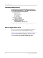
Common Applications .........................................................................................................5-2
Device Application View .....................................................................................................5-2
Hub Application ..................................................................................................................5-5
Fault Table ....................................................................................................................5-5
Fault Table view .....................................................................................................5-6
Fault Table .......................................................................................................5-6
Gauges Group ...............................................................................................................5-6
Gauges Table View .................................................................................................5-6
Gauges Table....................................................................................................5-6
Gauges Group View Fields ............................................................................5-10
Table Row Update view .......................................................................................5-10
Local SNMP ................................................................................................................5-11
Local SNMP View.................................................................................................5-11
SNMP Trap Table ..........................................................................................5-11
Poll Table.....................................................................................................................5-13
Poll Table View .....................................................................................................5-13
Poll Table........................................................................................................5-13
Power Supply Configuration ......................................................................................5-16
Power Supply Configuration View.......................................................................5-16
Power Supply Table .......................................................................................5-16
System Loader ............................................................................................................5-17
System Loader View.............................................................................................5-17
System Loader Table .....................................................................................5-17
iv
3Com LinkSwitch 1000/3000
Management Module Guide
Chapter 5
Application Views (Continued)
LinkSwitch 1000 Application ........................................................................................... 5-19
LinkSwitch 1000 Configuration view........................................................................ 5-19
Port Configuration Table ..................................................................................... 5-19
LinkSwitch 1000 VLAN Config view......................................................................... 5-21
VLAN Table.......................................................................................................... 5-21
LinkSwitch 1000 Unit Configuration view ............................................................... 5-22
Config Table ......................................................................................................... 5-22
LinkSwitch 1000 Database view ............................................................................... 5-23
Database Table..................................................................................................... 5-24
Chassis Configuration Application .................................................................................. 5-25
Chassis Configuration View....................................................................................... 5-25
Chassis Configuration Table view ............................................................................. 5-26
Physical Limits View.................................................................................................. 5-30
Chassis Service View ................................................................................................. 5-30
Service Address View ................................................................................................. 5-30
Facility Table View ..................................................................................................... 5-31
Serial I/f Application Configuration................................................................................. 5-33
V.24 Port Config View................................................................................................. 5-33
V.24 Port Config Table ......................................................................................... 5-33
Multi Repeater ........................................................................................................... 5-34
Multi Repeater Configuration View.................................................................... 5-34
Multi Repeater Port Configuration View............................................................ 5-35
Port Info Table ............................................................................................... 5-35
Port Config Table ........................................................................................... 5-36
Port Security............................................................................................................... 5-37
Port Security View ............................................................................................... 5-37
Port Security Table........................................................................................ 5-38
Port Address Table ........................................................................................ 5-39
Mrm Resilience........................................................................................................... 5-40
Mrm Resilience View ........................................................................................... 5-40
Mrm Resilience Table.................................................................................... 5-40
Mrm Resilience Standby Table..................................................................... 5-42
Index
9032294 E2
v
vi
3Com LinkSwitch 1000/3000
Management Module Guide
Figures
Chapter 1
Figure 1-1.
Figure 1-2.
Figure 1-3.
Figure 1-4.
Chapter 2
Figure 2-1.
Figure 2-2.
Figure 2-3.
Introduction
Using Double-Click Zones to Access SPECTRUM Views ................................... 1-3
Using the Icon Subviews Menu to Access SPECTRUM Views .......................... 1-4
Accessing Icon Subviews Menus from Labels ..................................................... 1-4
SPECTRUM Views Roadmap .............................................................................. 1-5
Device Views
Chassis Device View ............................................................................................. 2-2
Chassis Device Icon .............................................................................................. 2-3
Port Identification Label ...................................................................................... 2-5
Chapter 3
Configuration Views
Chapter 4
Event and Alarm Messages
Chapter 5
Application Views
Figure 5-1.
Figure 5-2.
Device Application View (Icon Mode) .................................................................. 5-3
Device Application View (List Mode) ................................................................... 5-4
9032294 E2
vii
Figures
viii
3Com LinkSwitch 1000/3000
Management Module Guide
Tables
Chapter 2
Table 2-1.
Table 2-2.
Chapter 3
Table 3-1.
Table 3-2.
Table 3-3.
Chapter 4
Table 4-1.
Chapter 5
Table 5-1.
Table 5-2.
Table 5-3.
Table 5-4.
Table 5-5.
Table 5-6.
Table 5-7.
Table 5-8.
Table 5-9.
Table 5-10.
Table 5-11.
Table 5-12.
Table 5-13.
Table 5-14.
Table 5-15.
Table 5-16.
Table 5-17.
Table 5-18.
Device Views
Device Icon Subviews Menu.................................................................................. 2-4
Port Identification Label Subviews Menu............................................................ 2-6
Configuration Views
Hub Configuration Possible Restart Values ........................................................ 3-4
Security Audit Log Results ............................................................................... 3-11
Poll Table Row Status Values............................................................................. 3-12
Event and Alarm Messages
3Com LinkSwitch 1000/3000 Events and Alarms .............................................. 4-1
Application Views
Hub Application-Specific Icon Subviews Menu Selections.................................. 5-5
Hub Sub-Application Icon Subviews Menu Selections ........................................ 5-5
Gauges Threshold Actions .................................................................................... 5-8
Gauges Recovery Actions ..................................................................................... 5-8
Gauge State Values ............................................................................................... 5-9
SNMP Trap Categories ...................................................................................... 5-12
SNMP Trap Row Status Values.......................................................................... 5-12
Poll Table Information Values ............................................................................ 5-15
Poll Table Row Status Values............................................................................. 5-15
Power Supply RBS Status Values ...................................................................... 5-16
System Loader Status States.............................................................................. 5-18
Chassis Configuration Application-Specific Icon Subviews Menu Selections.. 5-25
Service Type Categories ...................................................................................... 5-27
Chassis Congifuration View Type Values ......................................................... 5-28
Card Type Assignment Values............................................................................ 5-32
Port Security Need To Know Values .................................................................. 5-38
Row Status Values............................................................................................... 5-40
Mrm Resilience Main or Standby States............................................................ 5-41
9032294 E2
ix
x
3Com LinkSwitch 1000/3000
Management Module Guide
Preface
Use this guide as a reference for the 3Com LinkSwitch 1000/3000
management software. Before using this guide, you should be familiar with
SPECTRUM’s functions and navigational techniques as described in the
Administration documentation and the Operation documentation.
For the purposes of this guide, the 3Com LinkSwitch 1000/3000 is referred to
as “device.”
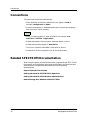
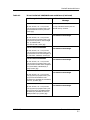
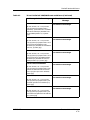
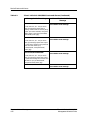
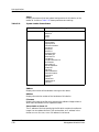
What Is in This Guide
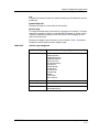
The organization of the 3Com LinkSwitch 1000/3000 Management
Module Guide is as follows:
Chapter
Description
Chapter 1
Describes the device, the management module,
and model types. This chapter also provides
information on accessing device specific views.
Introduction
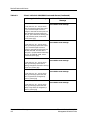
Chapter 2
Device Views
Chapter 3
Configuration Views
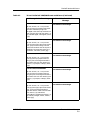
Chapter 4
Event and Alarm Messages
Chapter 5
Application Views
Describes the Device views representing the
device.
Describes the Configuration views for the device
and the network management information
provided by these views.
Lists and explains the event and alarm messages
generated in the Event Log or Alarm Manager for
the device.
Describes the Application views and applicationspecific information for this device.
9032294 E2
-xi
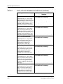
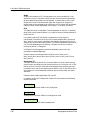
Conventions
Conventions
This guide uses the following conventions:
• Menu selections and buttons referenced in text appear in bold; for
example, Configuration or Detail.
• Buttons names appear in shadowed boxes when introducing paragraphs
describing their use; for example,
Help
• Menu navigation appears in order of selection; for example, Icon
Subviews -> Utilities -> Application.
• Referenced chapter titles and section headings appear in italics.
• Referenced documents appear in bold italics.
• The 3Com LinkSwitch 1000/3000 is referred to as “device.”
• References in blue are hypertext links for online documents.
Related SPECTRUM Documentation
When using this guide, you should have a clear understanding of SPECTRUM
functionality and navigational techniques as described in the Administration
documentation, the Operation documentation, and the following
documentation:
Report Generator User’s Guide
Getting Started with SPECTRUM for Operators
Getting Started with SPECTRUM for Administrators
How to Manage Your Network with SPECTRUM
Preface
-xii
3Com LinkSwitch 1000/3000
Management Module Guide
Other Related Documentation
Other Related Documentation
Refer to the following documentation for more information on managing
TCP/IP-based networks:
Martin, James, Kathleen Kavanagh Chapman, Joe Leben. Local Area
Networks: Architectures and Implementations, 2d ed. Englewood Cliffs,
NJ: Prentice Hall, 1994.
Rose, Marshall T. The Simple Book: An Introduction to Management of
TCP/IP-based Internets. Englewood Cliffs, NJ: Prentice Hall, 1991.
Stallings, William. Data and Computer Communications, 4th ed. New
York: Macmillan Publishing Company, 1994.
Tanenbaum, Andrew S. Computer Networks, 3d ed. Englewood Cliffs, NJ:
Prentice Hall, 1996.
9032294 E2
Preface
-xiii
Other Related Documentation
Preface
-xiv
3Com LinkSwitch 1000/3000
Management Module Guide
Chapter 1
Introduction
What Is in This Chapter
This chapter introduces the SPECTRUM Management Module for the 3Com
LinkSwitch 1000/3000. It describes the following:
•
•
•
•
3Com LinkSwitch 1000/3000
SPECTRUM Model Types
Accessing SPECTRUM views
SPECTRUM Views Roadmap
3Com LinkSwitch 1000/3000
The 3Com LinkSwitch 1000 and 3Com LinkSwitch 3000 are stackable Fast
Ethernet hubs that provide Fast Ethernet uplinks. The 3Com LinkSwitch
1000 provides 12 or 24 ports for twisted pair connections via RJ-45 connectors.
The 3Com LinkSwitch 3000 provides 8 ports for twisted pair connections via
RJ-45 connectors or 5 ports for fiber and one twisted pair RJ-45 connector.
The 3Com LinkSwitch 1000/3000 Management Module manages the 3Com
LinkSwitch 1000 and 3Com LinkSwitch 3000 devices using the Simple
Network Management Protocol (SNMP) Advanced Agent and the
Management Information Bases (MIBs) included with the management
module.
9032294 E2
1-1
SPECTRUM Model Type
SPECTRUM Model Type
The model type Hub3ComLS1000 refers to the management module software
package used to specify attributes, actions, and assosications for the physical
3Com LinkSwitch 1000 or 3000 device using the Simple Network
Management Protocol (SNMP) and Management Information Bases (MIBs)
for that device.
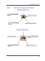
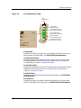
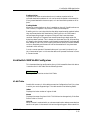
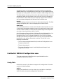
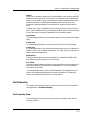
Accessing SPECTRUM Views
Icons and labels that display information within an icon, provide access to
SPECTRUM views. This is done using double-click zones (Figure 1-1) and Icon
Subviews menu selections (Figure 1-2).
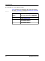
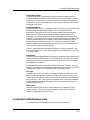
To access the Icon Subviews menu as shown in Figure 1-2 and Figure 1-3, do
the following:
1. Highlight the icon or label.
2. From the View menu select Icon Subviews or click the applicable mouse
button (middle or right). Refer to the SPECTRUM Views Reference for
information on configuring your mouse.
Introduction
1-2
3Com LinkSwitch 1000/3000
Management Module Guide
Accessing SPECTRUM Views
Figure 1-1.
Using Double-Click Zones to Access SPECTRUM Views
Accesses the Configuration views;
see Chapter 3, Configuration Views.
Accesses the Device Topology view;
refer to the SPECTRUM Views
Reference.
Model Name
Accesses the Device views;
see Chapter 2, Device Views.
Hub3ComLS1000
Accesses the Performance view;
refer to the SPECTRUM Views
Reference.
Accesses the Application views;
see Chapter 5, Application Views.
Accesses the Configuration views;
see Chapter 3, Configuration Views.
Accesses the Device views;
see Chapter 2, Device Views.
Model Name
Accesses the Performance view;
refer to the SPECTRUM Views
Reference.
Hub3ComLS1000
Accesses the Device Topology view;
refer to the SPECTRUM Views
Reference.
9032294 E2
Accesses the Application view;
see Chapter 5, Application Views.
Introduction
1-3
Accessing SPECTRUM Views
Figure 1-2.
Using the Icon Subviews Menu to Access SPECTRUM Views
Model Name
Hub3ComLS1000
View
Go Back
Ctrl+b
Go Up
Icon Subviews
View Path
New View
Bookmarks
View History
Current View Info...
Notes...
Jump by name...
Zoom
Map Hierarchy
Figure 1-3.
Close
Ctrl+c
Navigate
Alarms
Performance
Notes...
Utilities
Zoom
Device
Chassis
DevTop
Interface
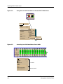
Accessing Icon Subviews Menus from Labels
1
1
2
3
4
5
6
7
8
9
10 11 12 13 14 15
Oper Oper Oper Oper Oper Oper Oper Oper Oper Oper Oper Oper Oper Oper Oper
Enab Enab Enab Enab Enab Enab Enab Enab Enab Enab Enab Enab Enab Enab Enab
Note Note Note Note Note Note Note Note Note Note Note Note Note Note Note
LS1000-24
0
0
0
0
Close
Alt+F4
Navigate
Alarms
Performance
Notes...
Utilities
Zoom
Module Notes
Module Configuration
Module Performance
Introduction
1-4
0
0
0
0
0
0
0
0
0
0
0
Common
Device-Specific
3Com LinkSwitch 1000/3000
Management Module Guide
SPECTRUM Views Roadmap
SPECTRUM Views Roadmap
Figure 1-4 shows a “roadmap” of the SPECTRUM views for this device. These
views are accessible from double-click zones (Figure 1-1) and Icon Subviews
menus (Figure 1-2 and Figure 1-3).
Figure 1-4.
SPECTRUM Views Roadmap
Performance views; refer to the
SPECTRUM Views Reference.
Chassis Device View
Interface Device View
This view is not supported for this
release.
Device views;
see Chapter 2, Device Views.
Device Configuration View
Hub Configuration View
Configuration views;
see Chapter 3, Configuration Views.
End Station View
Security View
Model Name
Hub3ComLS1000
Poll Table View
Interface Configuration Views
Device Application View
Application views;
see Chapter 5, Application Views.
Hub Application
LinkSwitch 1000 Application
Chassis Configuration Application
DevTop views; refer to the
SPECTRUM Views Reference.
9032294 E2
Serial I/f Application Configuration
Introduction
1-5
SPECTRUM Views Roadmap
Introduction
1-6
3Com LinkSwitch 1000/3000
Management Module Guide
Chapter 2
Device Views
What Is in This Chapter
This chapter describes the following device views available for the 3Com
LinkSwitch 1000/3000.
• Chassis Device view
• Interface Device view (This view is not supported for this release)
See Chapter 1, Introduction, for information on Accessing SPECTRUM Views.
9032294 E2
2-1
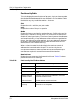
Chassis Device View
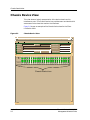
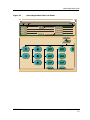
Chassis Device View
This view shows a logical representation of the device chassis and its
interfaces or ports. The Chassis Device icon provides menu and double-click
zone access to the views that monitor the interfaces.
Figure 2-1 shows an example of the Chassis Device view for the 3Com
LinkSwitch 1000.
Figure 2-1.
Chassis Device View
Example of type Hub3ComLS1000 of Landscape daedalus:Primary
*
File
View
Help?
Net Addr
Model Name
Contact
Manufacturer
Description
Device Type
Location
1
Sys Up Time
Prime-App
1
2
3
4
5
6
7
8
9
Serial Number
10 11 12 13 14 15 16 17 18 19 20 21 22 23 24 25 26
Oper Oper Oper Oper Oper Oper Oper Oper Oper Oper Oper Oper Oper Oper Oper Oper Oper Oper Oper Oper Oper Oper Oper Oper Oper Oper
Enab Enab Enab Enab Enab Enab Enab Enab Enab Enab Enab Enab Enab Enab Enab Enab Enab Enab Enab Enab Enab Enab Enab Enab Enab Enab
Note Note Note Note Note Note Note Note Note Note Note Note Note Note Note Note Note Note Note Note Note Note Note Note Note Note
LS1000-24
0 0 0 0 0 0 0 0 0 0 0 0 0 0 0 0 0 0 0 0 0 0 0 0 0 0
Chassis Device Icon
Device Views
2-2
3Com LinkSwitch 1000/3000
Management Module Guide
Chassis Device View
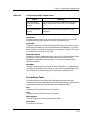
Chassis Device Icon
Chassis Device Icon
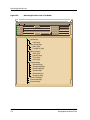
This icon is a logical representation of the physical device and its front panel
interfaces. This section describes the information available from the Chassis
Device icon. Figure 2-2 shows an example of the Chassis Device icon for the
3Com LinkSwitch 1000.
NOTES
The callouts displayed in this illustration identify the label name and the
view to which it provides double-click access. For example: Module Number/
Module Notes View displays the device model number and provides doubleclick access to the Module Notes view.
The menus displayed in the illustration are the Icon Subviews menus for
that label.
Figure 2-2.
Chassis Device Icon
Device
Identification
Label
Module Number/
Module Notes View
1
1
2
Port
Identification
Label
3
4
5
6
7
8
9
10 11 12 13 14 15 16
Oper Oper Oper Oper Oper Oper Oper Oper Oper Oper Oper Oper Oper Oper Oper Oper
Enab Enab Enab Enab Enab Enab Enab Enab Enab Enab Enab Enab Enab Enab Enab Enab
Note Note Note Note Note Note Note Note Note Note Note Note Note Note Note Note
Device Type Label
Close
Navigate
Alarms
Performance
Notes...
Utilities
Zoom
Module Notes
Module Configuration
Module Performance
9032294 E2
LS1000-24
Alt+F4
0 0 0 0 0 0 0 0 0 0 0 0 0 0 0 0
Close
Navigate
Alarms
Performance
Notes...
Utilities
Zoom
Port Notes
Port Configuration
Port Detail
Port Performance
Alt+F4
Device Views
2-3
Chassis Device View
Chassis Device Icon
Module Identification Label
This label provides the following information (see Figure 2-2):
Module Number
Displays the position of the module in the hub stack. Double-click this area to
open the Notes view described in the SPECTRUM Views Reference.
Device Type Label
Identifies the type of device.
Module Icon Subviews Menu
Table 2-1 lists each of the device-specific Icon Subviews menu selections
available for these devices. For information on Accessing SPECTRUM Views
see Chapter 1, Introduction.
Table 2-1.
Device Icon Subviews Menu
Menu Selection
Description
Module Notes
Opens the Notes view described in the
SPECTRUM Views Reference.
Module Configuration
Opens the Module Configuration View described
in Chapter 3, Configuration Views.
Module Performance
Opens the Module Performance view described in
the SPECTRUM Views Reference.
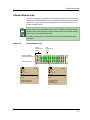
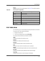
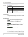
Port Identification Label
This label provides access to the Icon Subviews menu for the individual ports.
It contains the following information (see Figure 2-3):
NOTES
The callouts displayed in this illustration identify the label name and the
view to which it provides double-click access. For example: Port Number/Port
Notes View displays the port number and provides double-click access to the
Port Notes view.
The menus displayed in the illustration are the Icon Subviews menus for that
label.
Device Views
2-4
3Com LinkSwitch 1000/3000
Management Module Guide
Chassis Device View
Figure 2-3.
Port Identification Label
Port
Identification
Label
11
Oper
Close
Navigate
Alarms
Performance
Notes...
Utilities
Zoom
Port Notes
Port Configuration
Port Detail
Port Performance
Alt+F4
Enab
Note
0
Port Number/
Port Notes View
Port Operation Status/
Port Configuration View
Port Enable Status/
Port Configuration View
Port Note Status/
Error Breakdown View
Port Statistics Field/
Port Performance View
Port Number
Displays the number of the port within the module. Double-click this area to
open the Notes view described in the SPECTRUM Views Reference.
Port Operation Status
Displays the operational status of the port. Possible values are Operational
and Nonoperational. Double-click this area to open the Port Configuration
View described in Chapter 3, Configuration Views.
Port Enable Status
Displays the enable status of the port. Possible values are Enable and Disable.
Double-click this area to open the Port Configuration View described in
Chapter 3, Configuration Views.
Port Note Status
Double-click this area to open the Notes view described in the SPECTRUM
Views Reference.
Port Statistics
Displays the number of packets transmitted. Double-click this area to open
the Error Breakdown view described in the SPECTRUM Views Reference.
9032294 E2
Device Views
2-5
Chassis Device View
Port Identification Label Subviews Menu
Table 2-2 describes the Port Identification Label Subviews menu selections.
See Chapter 1, Introduction, for information on Accessing SPECTRUM Views.
Table 2-2.
Port Identification Label Subviews Menu
Menu Selection
Device Views
2-6
Description
Port Notes
Opens the Notes view described in the SPECTRUM
Views Reference.
Port Configuration
Opens the Module Configuration view described in
Chapter 3, Configuration Views.
Port Detail
Opens the Error Breakdown view described in the
SPECTRUM Views Reference.
Port Performance
Opens the Module Performance view described in the
SPECTRUM Views Reference.
3Com LinkSwitch 1000/3000
Management Module Guide
Chapter 3
Configuration Views
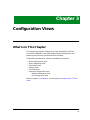
What Is in This Chapter
This chapter describes the Configuration views available for the 3Com
LinkSwitch 1000/3000. These views display network configuration and
operating information for the device and its interfaces.
The following Configuration views are available for this device:
•
•
•
•
•
•
Device Configuration View
Hub Configuration View
End Station View
Security View
Poll Table View
Interface Configuration Views
- Module Configuration View
- Port Configuration View
Refer to Chapter 1, Introduction, for information on Accessing SPECTRUM
Views.
9032294 E2
3-1
Device Configuration View
Device Configuration View
This view provides device-specific configuration information as well as access
to other views that allow you to configure device components.
To access the Device Configuration view do the following:
1. Highlight the device icon.
2. From the Icon Subviews menu, select Configuration.
Device Configuration Information
This section of the Configuration view displays the following device-specific
information:
Device Name
Displays the user-setable name of the device.
Contact Status
Indicates whether a connection with the device has been established. Possible
status messages include: Established, Lost and Initial.
Number of Interfaces
Displays the number of interfaces or ports available on this device.
Router Redundancy
This menu button allows you to set router redundancy to true or false.
This view also provides the following buttons, which allow you to configure
this device:
IF Address Translation
Opens the Interface Address Translation Table.
Reconfigure
Reconfigures the device with the current settings.
Interface Address Translation
This view provides the following fields:
Interface Index
Displays the number for a given interface or port.
Configuration Views
3-2
3Com LinkSwitch 1000/3000
Management Module Guide
Device Configuration View
Interface Configuration Table information
Physical Address
Displays the physical (MAC) address of the interface or port.
Network Address
Displays the network address of the interface or port.
Interface Configuration Table information
This table within the Device Configuration view provides the following
configuration information about the device’s interfaces or ports:
Index
Displays the number for a given interface or port.
Description
Displays a brief description of the device.
Type
Displays the type of hardware interface for the port. See the Administration
documentation for a full list of possible interface types.
Bandwidth
Displays the bandwidth of an interface or port.
Physical Address
Displays the physical (MAC) address of the interface or port.
Operation Status
Displays the current operational state of this port. Possible values are On, Off,
and Testing.
Admin Status
Displays the current operational state of this port (On, Off, or Testing).
Last Change
Display the date and time of the last change to the port’s status.
Queue Length
Displays the length of the queue.
Packet Size
Displays the size of packets moving through this port.
9032294 E2
Configuration Views
3-3
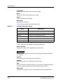
Hub Configuration View
Hub Configuration View
To access the Hub Configuration view do the following:
1. Highlight the device icon.
2. From the Icon Subviews menu, select Hub Config.
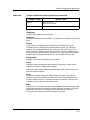
This view provides the following information and fields:
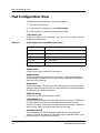
Last Restart Type
Displays the reason for the last restart. See Table 3-1 for a listing of possible
reasons and explanations.
Table 3-1.
Hub Configuration Possible Restart Values
Reason
Explanation
Other
None
Command
Management command
Watchdog
Watchdog timeout expiry
Power-reset
Power interruption
System-error
Reset switch pressed or system error
Restart Count
Displays the number of restarts for this device.
Restart Action
Allows you to select the action taken upon restart. Possible menu selections
are NoChange to restore the device to the previous settings and Restart to
select the current settings.
Reset Action
Allows you to select the action taken upon resetting the hub. Possible menu
selections are NoChange to select the current settings and ManDefaultReset
to restore the manufacturer’s defaults.
PROM Sw Ver No
Displays the PROM software version number.
Last System Error
Displays the error code for the latest system error. On startup this field is set
to the last NVRAM system error code. When the system issues a trap
indicating the latest system error number, the value in NVRAM is set to zero.
After the next restart this field would have a value of zero.
Heartbeat Interval
The time between successive heartbeat events sent to the management
station, in seconds. An interval of 0 indicates that no heartbeat events are to
be sent. Values up to 65535 can be entered.
Configuration Views
3-4
3Com LinkSwitch 1000/3000
Management Module Guide
Hub Configuration View
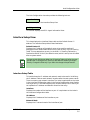
The Hub Configuration view also provides the following buttons:
Interface Setup
This button displays the Interface Setup View.
Ascii Agent Info
This button displays the ASCII Agent Information View.
Interface Setup View
This view displays the Interface Setup table and the Default Router IP
address. The Interface Setup table is described below.
Default Router IP
Displays the IP address of the default router to be used for sending IP
datagrams to the remote destinations which have no entry in the IP Routing
Table. This corresponds to an entry in the MIB-II IP Routing Table with a
Destination field of “0.0.0.0” (the default router) which is set up from this field
after a system restart.
NOTE
Changes to this field do not affect the IP Routing Table until after the next
system reset. To change the IP Routing Table without resetting, change it
directly. Change this filed only if you want the change to be permanent.
Interface Setup Table
This table shows the IP address and network mask to be used in initializing
the IP Address Table on each network interface after the next system restart.
There is one entry per network interface. The Index is equivalent to the Index
in the Interface Configuration table in the Device Configuration view. Doubleclicking an entry in this table displays the Interface Setup View in which you
can update the IP Address and Network Mask for that entry.
Interface
Displays the number of the interface or port. It is equivalent to the Index in
the Interface Configuration table.
IP Address
Displays the IP Address of the interface or port.
Network Mask
Displays the IP network mask of the interface of port.
9032294 E2
Configuration Views
3-5
End Station View
ASCII Agent Information View
ASCII Agent Information View
This view displays information about who is logged in to the device, whether
they are currently active, and the time they logged in. These fields are
updated by an ASCII agent such as a local terminal or a remote login.
This view displays the following fields:
User Name Last Attempted Login
Displays the ASCII string entered as the user name when last attempting to
login.
Login Status
Displays the status of the last attempted login.
Time Attempted Login
Displays the time of the last login attempt in hundredths of a second since the
system was last restarted.
End Station View
The End Station database maintains information relating end station address
information to device port for 802.3 repeater-type devices. This view allows
you to view and modify the address information for the device.
NOTE
The End Station database is global and applies across all devices in the
stack. There is no distinction between units on one repeater and those on
another. Given a unit number, the manager can read the configuration values
to determine the actual repeater association.
To access the End Station view do the following:
1. Highlight the device icon.
2. From the Icon Subviews menu, select Endstation Config.
This view provides the following information and fields:
Flush Database
Allows you to empty the database.
Database State
Displays NoChange until a change is made to the End Station database. It
then displays Modified until reset.
Configuration Views
3-6
3Com LinkSwitch 1000/3000
Management Module Guide
End Station View
This view also includes the following buttons:
Modified Table
Accesses the EndStation Modified Table view.
End Station Table
Accesses the EndStation Table view.
Port Access Table
Accesses the EndStation Port Access Table view.
EndStation Modified Table view
This table displays only those entries in the database with the Modified Flag
set. Any entries that have changed since last viewed by a manager will be
displayed in this view. This view is sorted by Address Type.
For information about individual fields see the EndStation Table view,
described below.
EndStation Table view
This table displays the entire contents of the database indexed by end station
address.
NOTES
The repeater number reported will change if the repeater within a device is
moved to another device or if the unit is isolated.
An address is only reported once. If an address that is already present in the
database is found on another port, the original record is changed and flagged
as modified.
This table displays the following:
Address Type
The end station database is capable of storing information for a number of
protocols, each with its own addressing format. This parameter allows access
to the database indexed on address type.
IP Address
The IP address, if relevant.
9032294 E2
Configuration Views
3-7
Security View
EndStation Port Access Table view
MAC Address
The MAC address, if relevant.
Slot
Displays the number of the unit on which this address was learned.
Port
Displays the port number within the unit on which this address was learned.
EndStation Port Access Table view
This table displays only those entries in the database with the Modified Flag
set. Any entries that have changed since last viewed by a manager will be
displayed in this view. This view is similar to the EndStation Modified Table
view, but is sorted by Slot andPort rather than Address Type.
For information about individual fields see the EndStation Table view,
described on Page 3-7.
Security View
To access the Security view do the following:
1. Highlight the device icon.
2. From the Icon Subviews menu, select Security.
This view provides the following information and fields:
Security Enable Table
This table displays permission for access to the device from each of its
interfaces. Users are assigned security levels in the Security Users Table view.
Double-clicking an entry in this table displays the Security Enable Table
Entry view.
Security Level
Displays the security level for the table. This field also acts as the index for the
table. Possible values are Monitor, SecureMonitor, Manager, Specialist, and
Security.
The following fields have possible values of Enable, Disable,
PermanentlyEnabled, and PermanantlyDisabled. You can change these fields
from the Security Enable Table Entry view.
Configuration Views
3-8
3Com LinkSwitch 1000/3000
Management Module Guide
Security View
Community
The community SNMP access permission.
Secure
The secure SNMP access permission.
Terminal
The local terminal access permission.
Telnet
The Telnet access permission.
FrontPanel
The front panel access permission.
The Security View also includes the following buttons:
Security Users
Accesses the Security Users Table view
Security Audit Log
Accesses the Security Audit Table view.
Security Users Table view
This view allows you to add and delete users and to modify their security
levels. The default users, Monitor, Manager, and Security, can not be deleted.
Double-clicking an entry in this table displays the Security Enable Table
Entry view.
This table displays the following:
Status
Displays the user status. Possible values are Valid and Invalid. A value of
Invalid means the user can no longer access the device. The default users,
Monitor, Manager, and Security, can not have their status changed to Invalid.
You can update this field in the Security Users Table Entry view.
Name
Displays the user name. This is the index for the table. Empty user names are
not allowed.
Level
Displays the user access level. This access level defines the scope of
management this user can perform. The levels of security are the same as in
the Security Enable Table described on Page 3-8. You can update this field for
all users except the default users.
9032294 E2
Configuration Views
3-9
Security View
Password
Displays the password required for user confirmation when access is made
from the local serial port, the front panel, or through Telnet. The Password
field is only available in the Security Users Table Entry view and is a writeonly field.
Community
Displays a string identifying the user when access is through the original
community-based SNMP (RFC1157). You can update this field.
Local Party
Displays the local party identity of the user when access is through secure
SNMP. You can update this field.
Manager Party
Displays the manager party identity of the user when access is through secure
SNMP. You can update this field.
The Security Users Table view also includes the following button:
Add Entry
Allows you to add entries to the table.
Security Audit Table View
This view displays a record of all updates to the managed database of the
device. When the log is full the oldest entry is overwritten. Therefore, this log
should be read regularly by a management device so that a permanent record
of the management history can be stored.
This view can not be modified. It displays the following:
Index
Displays the index number for an entry. This is a value between 1 and 65535
which resets to 1 after reaching 65535.
Time
Displays the time of the last update request, in hundredths of a second since
the last system restart.
User
Displays the name of the user making the request.
Object
Displays the object identifier for the item being updated. This includes any
qualifier for the object.
Value
Displays the new value for the item.
Configuration Views
3-10
3Com LinkSwitch 1000/3000
Management Module Guide
Poll Table View
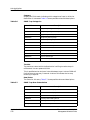
Result
Displays the result of the update request. See Table 3-2 for possible responses.
Table 3-2.
Security Audit Log Results
Result
Meaning
Success
Update succeeded
Pending
Update not yet completed
Too-big
Value rejected as too big for the item
Failed
Value rejected by access function
Locked
Item is locked by another manager
Security-violation
User does not have privileges for this request
No-such-function
Item is read-only
No-such-item
Item does not exist
Poll Table View
This view allows you to view and modify the polling information for the device.
To access the Poll Table view do the following:
1. Highlight the device icon.
2. From the Icon Subviews menu, select Poll Config.
This view provides the following information and fields:
Index
Displays the number of the interface or port.
Address
Displays the IP address of the interface or port.
Protocol
Displays the protocol used to reach the interface or port.
Rate
Displays the rate at which the interface or port is contacted.
Target
Displays the intended target of packets sent from the interface or port.
Poll Sent
Displays the number of polling attempts used to reach the target.
Trip Time
Displays the time taken to reach the target in miliseconds.
9032294 E2
Configuration Views
3-11
Poll Table View
Information
Displays any information returned from the target.
Alarm
Displays any alarms returned from the target.
Owner
Displays the owner of the target.
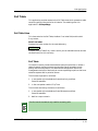
Row Status
The Status for this entry.
Table 3-3 shows possible values and descriptions.
Table 3-3.
Poll Table Row Status Values
Value
Description
Active
This status can be displayed and set
NotinService
This status can be displayed and set
NotReady
This status can be displayed but not set
Create&Go
Used only when adding entries
Create&Wait
Used only when adding entries
Destroy
Deletes the entry
The Poll Table View also displays the following information:
Next Free Index
Displays the index number assigned to any new entries.
Add Entry
Allows you to add entries to the Poll Table. This button accesses a view with
the following:
Instance
Allows you to enter the instance for the new entry.
Address
Allows you to enter the IP Address for the new entry.
Rate
Allows you to enter the polling interval for the new entry. Possible values are
Once-Only, 30-Seconds, Minute, 5-Minutes, 30-Minutes, and Hour.
Row Status
The Status for this entry. Table 3-3 shows possible values and descriptions.
Configuration Views
3-12
3Com LinkSwitch 1000/3000
Management Module Guide
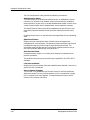
Interface Configuration Views
Interface Configuration Views
These views provides access to configuration and operating statuses for both
modules and the ports which they contain.
Module Configuration View
This view provides information on the configuration and operating status of
the module.
To access the Module Configuration view do the following:
1. Within the Chassis Device view, highlight the module icon.
2. From the Icon Subviews menu, select Module Configuration.
The Module Configuration view provides the following information:
Operational Status
Displays the status of the module. Possible values are operational,
notoperational and unknown.
Last Status Change
Displays the system up time at the time when the value of the operational
status object for this group last changed. A value of zero indicates that the
group's status has not changed since the agent was last restarted.
Port Capacity
Displays the number of ports on the module.
Module Type (OID)
Displays the Object IDentifier (OID) of the MIB for this device.
Module Description
Displays a brief description of the device.
Port Configuration View
This view provides information on the configuration and operating status of a
port within a module.
To access the Port Configuration view do the following:
1. Within the Chassis Device view, highlight the port icon.
2. From the Icon Subviews menu, select Port Configuration.
9032294 E2
Configuration Views
3-13
Interface Configuration Views
The Port Configuration view provides the following information:
Administrative Status
This field allows you to enable and disable the port. A disabled port neither
transmits nor receives. Once disabled, a port must be explicitly enabled to
restore operation. A port which is already disabled when power is lost or when
a reset is exerted shall remain disabled when normal operation resumes.
The Administrative Status value takes precedence over Auto Partition and
functionally operates between the auto-partition mechanism and the AUI/
PMA.
Enabling the port sets it to notAutoPartitioned regardless of its pre-disabling
state.
Operational Status
Displays the port's operational state. Possible values are operational,
notOperational, and notPresent. The operational state indicates that the port
is enabled and working, even though it might be auto-partitioned. The
notPresent state indicates the port is physically removed (note this may or
may not be possible depending on the type of port.)
Auto Partition State
Indicates whether the port is currently partitioned by the repeater's autopartition protection.
The conditions that cause port partitioning are specified in the IEEE 802.3
Standard.
Last Source Address
Displays the Source Address of the last readable frame received. If there is no
data 0.0.0.0.0.0 is displayed.
Source Address Changes
This counter is incremented by one for each time the Last Source Address
attribute changes. This may indicate whether a link is connected to a single
DTE or another multi-user segment. The approximate minimum time for
rollover of this counter is 81 hours.
Configuration Views
3-14
3Com LinkSwitch 1000/3000
Management Module Guide
Chapter 4
Event and Alarm Messages
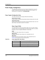
What Is in This Chapter
This chapter lists the types of events and alarms generated by the 3Com
LinkSwitch 1000/3000 and provides any probable cause messages
corresponding to these alarms.
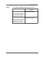
Device Events and Alarms
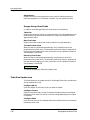
Table 4-1 lists the SPECTRUM database directory paths (in bold) and the
messages displayed for the Event Log and Alarm Manager when applicable.
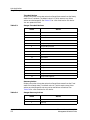
Table 4-1.
3Com LinkSwitch 1000/3000 Events and Alarms
Message in the Event Log
Alarm View Probable Cause
Message
CsEvFormat/Event00010306
No Probable cause message.
{d “%w- %d %m-, %Y - %T”} A(n) {t}
device, named {m}, has been cold
started. (event [{e}])
CsEvFormat/Event00010307
No Probable cause message.
{d “%w- %d %m-, %Y - %T”} A(n) {t}
device, named {m} has been warm
started. (event [{e}])
9032294 E2
4-1
Device Events and Alarms
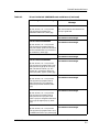
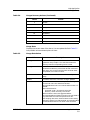
Table 4-1.
3Com LinkSwitch 1000/3000 Events and Alarms (Continued)
Message in the Event Log
CsEvFormat/Event00010308
Alarm View Probable Cause
Message
CsPCause/Prob00010308
{d “%w- %d %m-, %Y - %T”} A(n) {t}
Communication link is down.
device, named {m}, has detected a
communication Link Down. (event [{e}])
CsEvFormat/Event00010309
No Probable cause message.
{d “%w- %d %m-, %Y - %T”} A(n) {t}
device, named {m}, has detected a
communication Link Up. (event [{e}])
CsEvFormat/Event0001030a
CsPCause/Prob0001030a
{d “%w- %d %m-, %Y - %T”} A(n) {t}
device, named {m}, has detected an
Authentication Failure. (event [{e}])
Authorization failure. Other user is trying
to connect to device with an invalid
community string.
CsEvFormat/Event0001030b
CsPCause/Prob0001030b
{d “%w- %d %m-, %Y - %T”} A(n) {t}
Lost contact with EGP neighbor.
device, named {m}, has detected an EGP
Neighbor Loss. EGP Neighbor IP
address is {O 1}. (event [{e}])
CsEvFormat/Event00ea0013
No Probable cause message.
{d “%w- %d %m-, %Y - %T”} A 3Com
Hub, {t} (name {m}) Is informing the
manager that the device is still
operating. (event [{e}])
CsEvFormat/Event00ea0014
No Probable cause message.
{d “%w- %d %m-, %Y - %T”} A 3Com
Hub, {t} (name {m}) has had its
configuration modified via the ascii
agent. This may be through Telnet or
the V24 port. (event [{e}])
CsEvFormat/Event00ea0015
No Probable cause message.
{d “%w- %d %m-, %Y - %T”} A 3Com
Hub, {t} (name {m}) An user “{S 1}” has
attempted a login and failed three
times. The cause was {T comstat 2}.
(event [{e}])
Event and Alarm Messages
4-2
3Com LinkSwitch 1000/3000
Management Module Guide
Device Events and Alarms
Table 4-1.
3Com LinkSwitch 1000/3000 Events and Alarms (Continued)
Message in the Event Log
Alarm View Probable Cause
Message
CsEvFormat/Event00ea0016
No Probable cause message.
{d “%w- %d %m-, %Y - %T”} A 3Com
Hub, {t} (name {m}) a gauge {O 1} has
gone over its threshold {I 3}. The sample
period was {I 5} and the number of
samples used is {I 7}. (event [{e}])
CsEvFormat/Event00ea0017
No Probable cause message.
{d “%w- %d %m-, %Y - %T”} A 3Com
Hub, {t} (name {m}) a gauge {O 1} has
gone below its recovery level {I 3}. The
sample period was {I 5} and the number
of samples used is {I 7}. (event [{e}])
9032294 E2
Event and Alarm Messages
4-3
Device Events and Alarms
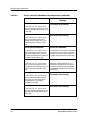
Table 4-1.
3Com LinkSwitch 1000/3000 Events and Alarms (Continued)
Message in the Event Log
Alarm View Probable Cause
Message
CsEvFormat/Event00ea0018
CsPCause/Prob00ea0018
{d “%w- %d %m-, %Y - %T”} A 3Com
Hub, {t} (name {m}) has reported that a
sytem load request has failed. The
reason was {T slstat 1}. (event [{e}])
When a system load is requested, a
response is returned immediately and the
load proceeds in the background. If an error
is detected this trap is generated indicating
the reason why in the status, as follows:
(1) file not found;
(2) access violation;
(4) illegal TFTP operation;
(5) unknown transfer ID;
(7) no such user;
(8) no response from the load server;
(9) the download could not be started
because of a lack of resources;
(10) the length of a record differs from
that implied by the value of the record
length field;
(11) the record type is not recognised;
(12) record checksum error;
(13) the device type in the file is incorrect;
(14) the software image is not suitable for
this version of the hardware;
(15) the first record in the file was not a
file header;
(16) The byte count reported in the file
trailer record differed from the
number of bytes actually received.
When loading a new image into the device
containing the agent itself, the agent first
reads the beginning of the image file to test
if it is accessible and contains a valid image.
If there is anything wrong, this trap is
generated, no download is performed and
the device continues to run uninterrupted.
If this check is successful the download
proper is begun. Should that fail, it is
simply retried continuously until either an
attempt succeeds or the device is reset.
CsEvFormat/Event00ea0019
No Probable cause message.
{d “%w- %d %m-, %Y - %T”} A 3Com
Hub, {t} (name {m}) reports the
endstation table has moved to the
modified state. (event [{e}])
Event and Alarm Messages
4-4
3Com LinkSwitch 1000/3000
Management Module Guide
Device Events and Alarms
Table 4-1.
3Com LinkSwitch 1000/3000 Events and Alarms (Continued)
Message in the Event Log
Alarm View Probable Cause
Message
CsEvFormat/Event00ea0020
CsPCause/Prob00ea0020
{d “%w- %d %m-, %Y - %T”} A 3Com
Hub, {t} (name {m}) reports the
endstation table is full. (event [{e}])
When the end-station table becomes full
this trap is generated.
CsEvFormat/Event00ea0024
No Probable cause message.
CsEvFormat/Event00ea0025
No Probable cause message.
{d “%w- %d %m-, %Y - %T”} A 3Com
Hub, {t} (name {m}) reports that the
slot. port. index {I 2} mau has entered or
left the available state. current state is
{T maustate 1}. (event [{e}])
CsEvFormat/Event00ea0026
No Probable cause message.
CsEvFormat/Event00ea0027
No Probable cause message.
{d “%w- %d %m-, %Y - %T”} A 3Com
Hub, {t} (name {m}) reports that a new
entity of service type {T service 1} has
been installed at location {I 2}. The
service ID is {I 5} and the entity has
name {S 9} and {I 7} ports. (event [{e}])
CsEvFormat/Event00ea0028
No Probable cause message.
{d “%w- %d %m-, %Y - %T”} A 3Com
Hub, {t} (name {m}) reports that an
entity of service ID {I 1} and entity
name {S 3} has been removed. (event
[{e}])
CsEvFormat/Event00ea0029
No Probable cause message.
{d “%w- %d %m-, %Y - %T”} A 3Com
Hub, {t} (name {m}) reports that an
entity of service ID {I 1} at the slot.
index is {I 4} has changed its facilitities
for its type {T etype 3} to {I 5}. (event
[{e}])
CsEvFormat/Event00ea0030
No Probable cause message.
{d “%w- %d %m-, %Y - %T”} A 3Com
Hub, {t} (name {m}) reports that a card
is added to the service {I 1}. (event [{e}])
9032294 E2
Event and Alarm Messages
4-5
Device Events and Alarms
Table 4-1.
3Com LinkSwitch 1000/3000 Events and Alarms (Continued)
Message in the Event Log
Alarm View Probable Cause
Message
CsEvFormat/Event00ea0031
No Probable cause message.
{d “%w- %d %m-, %Y - %T”} A 3Com
Hub, {t} (name {m}) reports that a card
has been removed from the service {I 1}.
(event [{e}])
CsEvFormat/Event00ea0032
No Probable cause message.
{d “%w- %d %m-, %Y - %T”} A 3Com
Hub, {t} (name {m}) reports that a
physical entity of service id {I 1} has
changed state to {T estate 3}. (event
[{e}])
CsEvFormat/Event00ea0033
CsPCause/Prob00ea0033
{d “%w- %d %m-, %Y - %T”} A 3Com
Hub, {t} (name {m}) reports that the
power requirements of the entities in
the chassis exceed the power capacity of
the power supplies. (event [{e}])
The combination of the power requirements
of all the entities in the chassis has been
calculated to exceed the power capacity of
the power supplies present in the chassis.
CsEvFormat/Event00ea0034
CsPCause/Prob00ea0034
{d “%w- %d %m-, %Y - %T”} A 3Com
Hub, {t} (name {m}) reports that the
managemant card temperature sensing
device is reporting DANGER. (event
[{e}])
Mounted on the Management card is a
temperature sensing device. This device
provides three output levels: OK, WARM
and DANGER. DANGER causes a trap to
be generated.
CsEvFormat/Event00ea0035
No Probable cause message.
{d “%w- %d %m-, %Y - %T”} A 3Com
Hub, {t} (name {m}) reports that the
status input {I 2} of name {S 3} has
changed state to {I 1} (1=Open,
2=Closed). (event [{e}])
CsEvFormat/Event00ea0036
No Probable cause message.
{d “%w- %d %m-, %Y - %T”} A 3Com
Hub, {t} (name {m}) reports that port {I
2} has learned a staion address {H 3}.
(event [{e}])
Event and Alarm Messages
4-6
3Com LinkSwitch 1000/3000
Management Module Guide
Device Events and Alarms
Table 4-1.
3Com LinkSwitch 1000/3000 Events and Alarms (Continued)
Message in the Event Log
Alarm View Probable Cause
Message
CsEvFormat/Event00ea0037
CsPCause/Prob00ea0037
{d “%w- %d %m-, %Y - %T”} A 3Com
Hub, {t} (name {m}) reports that a port
{I 2} has detected a security violation.
(event [{e}])
This trap indicates that this port has
detected security violation.
CsEvFormat/Event00ea0038
No Probable cause message.
{d “%w- %d %m-, %Y - %T”} A 3Com
Hub, {t} (name {m}) reports that a port
{I 2} has had its partion state changed
to {I 1} (1=Partitioned,
2=UnPartitioned). (event [{e}])
CsEvFormat/Event00ea0039
No Probable cause message.
{d “%w- %d %m-, %Y - %T”} A 3Com
Hub, {t} (name {m}) reports that a port
{I 2} has had its link state changed to {I
1} (1=Present, 2=Absent). (event [{e}])
CsEvFormat/Event00ea0040
No Probable cause message.
{d “%w- %d %m-, %Y - %T”} A 3Com
Hub, {t} (name {m}) reports that a port
{I 2} has had its Admin state changed to
{I 1} (1=Enabled, 2=Disabled) by a
gauge. (event [{e}])
CsEvFormat/Event00ea0041
No Probable cause message.
{d “%w- %d %m-, %Y - %T”} A 3Com
Hub, {t} (name {m}) reports that a port
{I 2} has had its Bandwith Used
threshold {I 3} exceeded. The Bandwith
used is {I 1} (event [{e}])
CsEvFormat/Event00ea0042
No Probable cause message.
{d “%w- %d %m-, %Y - %T”} A 3Com
Hub, {t} (name {m}) reports that a port
{I 2} has had its Errors/10000 packets
threshold {I 3} exceeded. The Errors/
10000 packets is {I 1} (event [{e}])
9032294 E2
Event and Alarm Messages
4-7
Device Events and Alarms
Table 4-1.
3Com LinkSwitch 1000/3000 Events and Alarms (Continued)
Message in the Event Log
Alarm View Probable Cause
Message
CsEvFormat/Event00ea0043
No Probable cause message.
{d “%w- %d %m-, %Y - %T”} A 3Com
Hub, {t} (name {m}) reports that a port
{I 2} in a resilience pair has had a
change in state and the active port has
been switched. The state of the main
port is {I 1} the state of the backup port
is {I 3} (1=Failed, 2=OK, 3=OK-AndActive) (event [{e}])
CsEvFormat/Event00ea0044
No Probable cause message.
{d “%w- %d %m-, %Y - %T”} A 3Com
Hub, {t} (name {m}) reports that a port
{I 2} in a resilience pair has had a
change in state and the active port has
not been switched. The state of the
main port is {I 1} the state of the backup
port is {I 3} (1=Failed, 2=OK, 3=OKAnd-Active) (event [{e}])
CsEvFormat/Event00ea0045
No Probable cause message.
{d “%w- %d %m-, %Y - %T”} A 3Com
Hub, {t} (name {m}) reports that a
topology change has ocuured in the ring
at time {I 1}. (event [{e}])
CsEvFormat/Event00ea0046
No Probable cause message.
{d “%w- %d %m-, %Y - %T”} A 3Com
Hub, {t} (name {m}) reports that the
main rings state has changed to {T
rstate 1}. (event [{e}])
CsEvFormat/Event00ea0047
No Probable cause message.
{d “%w- %d %m-, %Y - %T”} A 3Com
Hub, {t} (name {m}) reports that the
backup rings state has changed to {T
rstate 1}. (event [{e}])
Event and Alarm Messages
4-8
3Com LinkSwitch 1000/3000
Management Module Guide
Device Events and Alarms
Table 4-1.
3Com LinkSwitch 1000/3000 Events and Alarms (Continued)
Message in the Event Log
Alarm View Probable Cause
Message
CsEvFormat/Event00ea0048
No Probable cause message.
{d “%w- %d %m-, %Y - %T”} A 3Com
Hub, {t} (name {m}) reports that either
the main and backup rings have
wrapped or that the wrap condition has
been removed. The new wrap state is {I
1} (1=NotWrapped, 2=Wrapped). (event
[{e}])
CsEvFormat/Event00ea0049
No Probable cause message.
{d “%w- %d %m-, %Y - %T”} A 3Com
Hub, {t} (name {m}) reports that a MAU
port {I 2} has had a change in attach
state and the admin state of the port is
disabled. The new attach state is {I 1}
(1=Absent, 2=Present). (event [{e}])
CsEvFormat/Event00ea0050
No Probable cause message.
{d “%w- %d %m-, %Y - %T”} A 3Com
Hub, {t} (name {m}) reports that the
Ring In port has changed state while
the mode is fail-safe. The new Ring In
state is {I 1} (1=Open, 2=Wrap). (event
[{e}])
CsEvFormat/Event00ea0051
No Probable cause message.
{d “%w- %d %m-, %Y - %T”} A 3Com
Hub, {t} (name {m}) reports that the
Ring Out port has changed state while
the mode is fail-safe. The new Ring Out
state is {I 1} (1=Open, 2=Wrap). (event
[{e}])
CsEvFormat/Event00ea0060
No Probable cause message.
{d “%w- %d %m-, %Y - %T”} A 3Com
Hub, {t} (name {m}) reports that a MAU
port {I 2} has changed state due to
operation of ZDL or DRI. The new MAU
port state is {I 1} (1=Enabled,
2=Disabled). If disabled the reason is {I
3} (1=None, 2=Mgmt, 3=ZDL, 4=DRI).
(event [{e}])
9032294 E2
Event and Alarm Messages
4-9
Device Events and Alarms
Table 4-1.
3Com LinkSwitch 1000/3000 Events and Alarms (Continued)
Message in the Event Log
Alarm View Probable Cause
Message
CsEvFormat/Event00ea0061
No Probable cause message.
{d “%w- %d %m-, %Y - %T”} A 3Com
Hub, {t} (name {m}) reports that the
managed agent has recieved a reply to a
poll after a sequence of four or more unsuccessfull polls. The addres is {S 1}
with protocol {T pprot 3}. (event [{e}])
CsEvFormat/Event00ea0062
No Probable cause message.
{d “%w- %d %m-, %Y - %T”} A 3Com
Hub, {t} (name {m}) reports that the
managed agent has not recieved a reply
to a poll after a sequence of four unsuccessfull polls. The address is {S 1}
with protocol {T pprot 3}. (event [{e}])
CsEvFormat/Event00ea0063
No Probable cause message.
{d “%w- %d %m-, %Y - %T”} A 3Com
Hub, {t} (name {m}) reports that the
Resilient Backup Power Supply
connected to this repeater has
developed a fault. (event [{e}])
CsEvFormat/Event00ea0064
No Probable cause message.
{d “%w- %d %m-, %Y - %T”} A 3Com
Hub, {t} (name {m}) reports that the
Resilient Backup Power Supply
connected to this repeater has
recovered from a fault. (event [{e}])
CsEvFormat/Event00ea0066
No Probable cause message.
{d “%w- %d %m-, %Y - %T”} A 3Com
Hub, {t} (name {m}) reports that a port
{I 2} has seen an unrecognised MAC
address and is doing the following
action {I 1} (2=Notify, 3=Disconnect).
(event [{e}])
CsEvFormat/Event00ea0067
No Probable cause message.
{d “%w- %d %m-, %Y - %T”} A 3Com
Hub, {t} (name {m}) reports that a
repeater {I 2} has had its Bandwith
Used threshold {I 3} exceeded. The
Bandwith used is {I 1} (event [{e}])
Event and Alarm Messages
4-10
3Com LinkSwitch 1000/3000
Management Module Guide
Device Events and Alarms
Table 4-1.
3Com LinkSwitch 1000/3000 Events and Alarms (Continued)
Message in the Event Log
Alarm View Probable Cause
Message
CsEvFormat/Event00ea0068
No Probable cause message.
{d “%w- %d %m-, %Y - %T”} A 3Com
Hub, {t} (name {m}) reports that a
repeater {I 2} has had its Errors/10000
packets threshold {I 3} exceeded. The
Errors/10000 packets is {I 1} (event
[{e}])
CsEvFormat/Event00ea0069
No Probable cause message.
{d “%w- %d %m-, %Y - %T”} A 3Com
Hub, {t} (name {m}) reports that a card
{I 2} has had its Bandwith Used
threshold {I 3} exceeded. The Bandwith
used is {I 1} (event [{e}])
CsEvFormat/Event00ea0070
No Probable cause message.
{d “%w- %d %m-, %Y - %T”} A 3Com
Hub, {t} (name {m}) reports that a card
{I 2} has had its Errors/10000 packets
threshold {I 3} exceeded. The Errors/
10000 packets is {I 1} (event [{e}])
CsEvFormat/Event00ea0071
No Probable cause message.
{d “%w- %d %m-, %Y - %T”} A 3Com
Hub, {t} (name {m}) reports that a new
station has been learned. The station
info is {I 2} (slot. port. MAC-Address)
(event [{e}])
CsEvFormat/Event00ea0074
No Probable cause message.
{d “%w- %d %m-, %Y - %T”} A 3Com
Hub, {t} (name {m}) reports that a poll
has been replied to from address {I 1}.
(event [{e}])
CsEvFormat/Event00ea0075
No Probable cause message.
{d “%w- %d %m-, %Y - %T”} A 3Com
Hub, {t} (name {m}) reports that a poll
has failed to be replied to from address
{I 1}. (event [{e}])
9032294 E2
Event and Alarm Messages
4-11
Device Events and Alarms
Table 4-1.
3Com LinkSwitch 1000/3000 Events and Alarms (Continued)
Message in the Event Log
Alarm View Probable Cause
Message
CsEvFormat/Event00ea0078
No Probable cause message.
{d “%w- %d %m-, %Y - %T”} A 3Com
Hub, {t} (name {m}) reports that a
security violation has occured on port {I
2} (slot. port. MAC-Address). The port’s
admin status is now {I 3} (1=Enabled,
2=Disabled) (event [{e}])
CsEvFormat/Event00ea0079
No Probable cause message.
{d “%w- %d %m-, %Y - %T”} A 3Com
Hub, {t} (name {m}) reports that a port
{I 2} has had a change in auto partition
state. The new state is {I 1}.
(1=Partitioned, 2=Unpartitioned)
(event [{e}])
CsEvFormat/Event00ea0080
No Probable cause message.
{d “%w- %d %m-, %Y - %T”} A 3Com
Hub, {t} (name {m}) reports that a port
{I 2} has had a change in link state. The
new state is {I 1}. (1=Partitioned,
2=Unpartitioned) (event [{e}])
CsEvFormat/Event00ea0082
No Probable cause message.
Event and Alarm Messages
4-12
3Com LinkSwitch 1000/3000
Management Module Guide
Chapter 5
Application Views
What Is in This Chapter
This chapter describes the device-specific applications listed below for the
3Com LinkSwitch 1000/3000. The corresponding application model type is
shown in parentheses.
• Hub Application (3ComHubApp)
- Fault Table Application (3ComfaultApp)
- Gauges Group Application (3Comgauges2App)
- Local SNMP Application (3ComSnmpApp2)
- Poll Table Application (3CompollApp)
- Power Supply Application (3CompowerApp)
- System Loader Application (3ComsysLdApp2)
• 3Com LinkSwitch 1000 Application (3ComLS1000App)
• 3Com Chassis Application (3ComchassisApp)
• 3Com Serial Interface Application (3ComserIfApp)
- Multi Repeater Application(3CommultiApp2)
- Port Security Application (3ComSecPortApp)
- MRM Resilience Standby Application (3CommrmResApp)
9032294 E2
5-1
Common Applications
Common Applications
This device supports the following common applications described in the
Bridging Applications Reference, the MIB II Applications Reference,
and the Miscellaneous Applications Reference:
• MIB-II (SNMP2_Agent)
- ICMP (ICMP_App)
- System (System2_App)
- TCP (TCP2_App)
- UDP (UDP2_App)
• Generic Router (GenRtrApp)
- IP Routing (IP2RtrApp)
• Generic Bridging (Gen_Bridge_App)
- Static Bridging (Static_App)
- Transparent Bridging (Transparent_App)
The Standard RMON application is available if you purchase the associated
service. This application is described in its management module guide.
Device Application View
This view shows the common and device-specific applications supported by
this device and provides access to application-specific information.
See Chapter 1, Introduction, for information on Accessing SPECTRUM Views.
Figure 5-1 provides an example of an Application view in the icon mode.
Figure 5-2 provides an example of an Application view in the list mode.
To change the display mode, select View -> Mode -> List or Icon.
Application Views
5-2
3Com LinkSwitch 1000/3000
Management Module Guide
Device Application View
Figure 5-1.
Device Application View (Icon Mode)
Example of type Hub3ComLS1000 of Landscape daedalus: Primary
*
File
View
Help?
Net Addr
Model Name
Sys Up Time
Contact
Manufacturer
Description
Location
Device Type
Prime-App
Serial Number
Model Name
Hub3ComLS1000
Routing
Gen Bridge
GenRtrApp
Gen_Bridge
IP Routing
Static
IP2RtrApp
Static_App
Transparent
Transparnt
9032294 E2
MIB-2
Hub
LS100
SNMP2_Agent
3ComHubApp
3ComL
SNMP2_Agent
3ComHubApp
3ComL
ICMP
Fault Table
ICMP_App
3ComfaultApp
ICMP_App
3ComfaultApp
System
Gauges
System2_App
3Comgauges
System2_App
3Comgauges
TCP
Local SNMP
Application Views
5-3
Device Application View
Figure 5-2.
Device Application View (List Mode)
Example of type Hub3ComLS1000 of Landscape daedalus: Primary
*
File
Model Name
View
Help?
Net Addr
Contact
Manufacturer
Description
Location
Sys Up Time
Device Type
Prime-App
Serial Number
Hub3ComLS1000
GenRtrApp
IP2RtrApp
Gen_Bridge_App
Static_App
Transparnt_App
SNMP2_Agent
ICMP_App
System2_App
TCP2_App
UDP2_App
3ComHubApp
3ComfaultApp
3Comgauges2App
3ComSnmpApp2
3CompollApp
3CompowerApp
3ComsysLdApp
3ComLS1000App
3ComchassisApp
3ComserIfApp
Application Views
5-4
3Com LinkSwitch 1000/3000
Management Module Guide
Hub Application
Hub Application
This application provides access to hub functionality for this device. The
model type for this application is 3ComHubApp. Table 5-1 describes each of
the application-specific Icon Subviews menu selections for the Hub
application.
Table 5-1.
Hub Application-Specific Icon Subviews Menu Selections
Menu Selection
Description
Configuration
Described under Device Configuration View in Chapter 3,
Configuration Views
EndStation
Described under End Station View in Chapter 3,
Configuration Views
Security
Described under Security View in Chapter 3, Configuration
Views
Model Information
Opens the Model Information view described in the
SPECTRUM Views Reference.
The following applications are subordinate to the Hub application and have
the same Icon Subviews menu selections. Table 5-2 presents these selections.
•
•
•
•
•
•
Table 5-2.
Fault Table
Gauges Group
Local SNMP
Poll Table
Power Supply Configuration
System Loader
Hub Sub-Application Icon Subviews Menu Selections
Menu Selection
Description
Configuration
Accesses the view described in the relevant section below.
Model Information
Opens the Model Information view described in the
SPECTRUM Views Reference.
Fault Table
This application provides access to a table containing information on the
faults detected by this device. The model type for this application is
3ComfaultApp.
9032294 E2
Application Views
5-5
Hub Application
Gauges Group
Fault Table view
This view contains the Modified Flag menu button and the Fault Table.
Modified Flag
Be sure this flag is set to Clean-Read before examining the Fault Table. If it
has the value of Modified, the table has been updated during the read process.
Re-open the view to update the Fault Table.
Fault Table
This area of the Fault Table view displays information about faults detected
by this device.
Index
The index to the table.
Error Number
The number for this entry in the error log.
Time Stamp
The time when the fault occurred, in milliseconds since system startup.
Restart Count
The number of restarts already made at the time of this fault.
Gauges Group
This application provides access to a table containing information on the
operating levels of this device. The model type for this application is
3Comgauges2App.
Gauges Table View
This view contains the Gauge Table, several fields below the table, and the
Table Update button.
Gauges Table
This table allows you to set up alarms.
Double-clicking any of the fields within the table opens the Gauge Table Entry
view, which provides information for a specific row. Changes can not be made
Application Views
5-6
3Com LinkSwitch 1000/3000
Management Module Guide
Hub Application
Gauges Group
in the Gauge Table Entry view. To change the information in a field, access the
Table Row Update view by clicking the Table Update button.
Before updating any of the Gauge Table fields, turn the alarm off using the
Gauge State field. Turning the alarm off and on again will affect the data; the
sampling data, Value, Peak, and Status are not lost but any updates to the
index will fail since they are read-only.
Index
Displays the index number for the entry. These are allocated by the Alarms
Subsystem.
Object ID
Displays the Object ID and qualifier of the item to be monitored.
Item Type
Displays the type of object. Possible values are Counter, SignedMeter, or
UnSignedMeter. Counters always have positive values. UnSignedMeter can
be positive or negative. SignedMeter explicitly state positive or negative.
SPA
Displays the number of samples per average used to calculate the Alarm
Value. Possible values are Non Averaging, Two Samples, Three Samples, and
Max Samples. The default value is 4, Max Samples. If a value of 1 is used
there is no averaging and the Value field shows the most recent sample.
Period
Displays the number of seconds between samples. The averaging period is the
Period multiplied by the SPA.
Value
Displays the most recently computed average. For a signed or unsigned meter,
this is the average of the samples. For a counter, the value is the average of
the differences between successive samples.
Counters and unsigned meters are unsigned 32-bit values with a maximum
value of 4294967295. Signed meters are signed 32-bit values and have a
maximum value of + or - 21474833647 divided by the value in the SPA field.
Peak
Displays the highest recorded alarm value. This is a 32-bit value, signed or
unsigned depending on the Item Type.
Threshold
Displays the value at which the Gauge State moves from the Ready state to
the Fired state and the Threshold Action is taken. This is a 32-bit value,
signed or unsigned depending on the Item Type.
Recovery
Displays the value at which the Gauge State recovers from the Fired state to
the Ready state and the Recovery Action is taken. This is a 32-bit value,
signed or unsigned depending on the Item Type.
9032294 E2
Application Views
5-7
Hub Application
Gauges Group
Threshold Action
Displays the action to be taken when the Gauge State moves from the Ready
state to the Fired state. The default value is 2, which sends a trap. Other
actions are device-specific. See Table 5-3 for a list of actions for this device.
You can update this field.
Table 5-3.
Gauges Threshold Actions
Value
Action
1
NoAction
2
SendTrap
3
Disable
4
Enable
5
NotifyAndBlipPortOff
6
NotifyAndBlipCardOff
8
NotifyAndDisablePort
9
NotifyAndDisableCard
12
BlipPortOff
13
BlipCardOff
14
DisablePort
15
DisableCard
18
NotifyAndResilientSwitch
19
NotifyBandwidthExceeded
20
NotifyErrorsExceeded
22
NotifyPollFailed
23
NotifyFilterBrodgePort
Recovery Action
Displays the action to be taken when the Gauge State moves from the Fired
state to the Ready state. The default value is 2, which sends a trap. Other
actions are device-specific and may not be available on all devices. See
Table 5-4 for a list of actions for this device.
Table 5-4.
Gauges Recovery Actions
Value
Application Views
5-8
Action
1
NoAction
2
SendTrap
3Com LinkSwitch 1000/3000
Management Module Guide
Hub Application
Gauges Group
Table 5-4.
Gauges Recovery Actions (Continued)
Value
Action
3
Disable
4
Enable
10
NotifyAndEnablePort
11
NotifyAndEnableCard
16
EnablePort
17
EnableCard
21
NotifyPollSuccess
23
NotifyUnFilterBridgePort
Gauge State
Displays the current state of the alarm. You can update this field. Table 5-5
lists possible values and descriptions of them.
Table 5-5.
Gauge State Values
Value
9032294 E2
Description
OnTriggersEnabled
The normal activity state of the alarm. The value is
updated on every sample. If it crosses the Threshold or
Recovery level the corresponding action is taken.
OnTriggersDisabled
Used when a new device or alarm is set up and the
Threshold and Recovery values have not been calibrated.
The alarm runs as normal and the Value and Peak fields
are updated, but no action is taken.
Off
Deactivates the alarm. This allows it to be configured
safely.
Deleted
Invalidates the alarm. Values are no longer updated.
AutoCalibrate
Updates the Threshold and Recovery fields according to the
current Peak value. The State then becomes
onTriggersEnabled. This can not be set while the alarm is
deleted.
After autoCalibration:
Threshold = Peak * Threshold Level Scaler
Recovery = Peak * Recovery Level Scaler
When the State is either onTriggersEnabled or
onTriggersDisabled, all fields for the alarm are validated. If
any of the fields are invalid the operation will fail.
The sampling data, Value, Peak and State can be reset by
setting this field to onTriggersEnabled, onTriggersDisabled
or autoCalubrate when it is in either of the “on” states.
Application Views
5-9
Hub Application
Gauges Group
Gauge Owner
Displays the entity that configured this entry and is therefore using the
resources assigned to it. The default is System. You can update this field.
Gauges Group View Fields
In addition to the Gauges Table, this view contains the following:
Table Size
Displays the number of entries in the Gauges Table. This value depends on the
requirements and resources of the device. In practice the maximum will be
approximately 1000.
Next Free Index
Displays the index number that must be used for the next table entry.
Threshold Level Scaler
When the alarm is calibrated automatically, the Threshold is set to this
percentage of the Peak value. The automatic calibration value is computed as
the Peak value divided by this value, times 100. You can update this field to a
value between 1 and 65535.
Recovery Level Scaler
When the alarm is calibrated automatically, the Recovery is set to this
percentage of the Peak value. The automatic calibration value is computed as
the Peak value divided by this value, times 100. You can update this field to a
value between 1 and 65535.
Table Update
This button accesses the Table Row Update view.
Table Row Update view
This view allows you to update entries in the Gauges Table. Only one attribute
can be modified at a time.
Configure Obj ID
Enter the Object ID of the entry that you want to update.
Configure Column
Select the attribute that you want to update. Possible values are provided at
the bottom of the view. The entries in the list change depending on the Object
ID selected.
Configure Value
Enter the new value for the selected attribute. Possible values are provided at
the bottom of the view.
Application Views
5-10
3Com LinkSwitch 1000/3000
Management Module Guide
Hub Application
Local SNMP
Local SNMP
This application provides access to the Local SNMP view, allowing you to set
SNMP Traps for this device. The model type for this application is
3ComSnmpApp2.
Local SNMP View
This view contains the SNMP Trap Table, and below the table, the Next Free
Index field and the Add Entry button.
Next Free Index
Displays the index value for the next table entry.
Add Entry
Accesses the Add SNMP Table Entry view.
SNMP Trap Table
This table stores the destination addresses of SNMP managers that wish to
receive traps from this device. Double-clicking an entry in this table displays
the SNMP Trap Table Entry view in which you can update several fields.
Index
Displays the index for this entry.
Destination
Displays the network address of the device to which the SNMP traps will be
sent.
Protocol
Displays the transport protocol to use when sending the trap. Possible values
are IP, IPX, and None.
Community
Displays the SNMP community string to be used when sending the trap. You
can update this field.
9032294 E2
Application Views
5-11
Hub Application
Local SNMP
Category
Displays the 32-bit mask indicating which categories of traps in which the
Destination is interested. Table 5-6 shows possible values and descriptions.
Table 5-6.
SNMP Trap Categories
Value
Description
‘00000001’h
High priority configuration traps
‘00000002’h
Low priority configuration traps
‘00000004’h
High priority security traps
‘00000008’h
Low priority security traps
‘00000010’h
Alarms and polling traps
‘00000020’h
Regular heartbeat traps
‘00000040’h
End Station Table traps
‘00000080’h
Reserved
‘00000100’h
Physical entity traps
‘00000200’h
Facility traps
‘00000400’h
Service related traps
0xFFFFFFFF
Enables all traps
Throttle
The maximum rate at which the Destination is willing to receive traps in
milliseconds. You can update this field.
This is specified as the minimum interval between traps. A value of 2000 will
limit the traps to one every 2 seconds. A value of 0 indicates that no trap
throttling is required.
Row Status
The Status for this entry. Table 5-7 shows possible values and descriptions.
Table 5-7.
SNMP Trap Row Status Values
Value
Application Views
5-12
Description
Active
This status can be displayed and set
NotinService
This status can be displayed and set
NotReady
This status can be displayed but not set
Create&Go
Used only when adding entries
Create&Wait
Used only when adding entries
Destroy
Deletes the entry
3Com LinkSwitch 1000/3000
Management Module Guide
Hub Application
Poll Table
Poll Table
This application provides access to the Poll Table view, which presents a table
containing polling information for this device. The model type for this
application is 3CompollApp.
Poll Table View
This view contains the Poll Table, the Next Free Index field, and the Add
Entry button.
Next Free Index
Displays the index number for the next table entry
Add Entry
Accesses the Poll Table Entry view in which you can add table entries and set
the Row Status for this new entry.
Poll Table
This table is used to provide remote device monitoring facilities. It allows a
table of network devices to be set up and polled. Setup variables include
polling interval and protocol. This table can be configured to inform the
management station(s) of devices that are not responding to polls or that have
stated to respond after a period of silence.
The minimal single poll is as follows:
1. In one packet write the Address, Rate=Once-Only, and Row
Status=Create&Go.
2. In the next packet read the Trip Time.
The minimal monitoring of a device is as follows:
1. In one packet write the Address, Rate=30-seconds and Row
Status=Create&Go.
2. Wait for traps to come in.
The first row of the table is only used for once-only polls.
NOTE
9032294 E2
Application Views
5-13
Hub Application
Index
Displays the index number to the entry.
Address
Displays the network address of the device to monitor. Typically this is an IP,
IPX, or MAC address. You can update this field using the Poll Table Entry
view. The following formats can be used:
• IP:nnn.nnn.nnn.nnn - dotted format
• IPX:AABBCCDD:AABBCCDDEEFF - network:node
Protocol
Displays the protocol used to monitor the device. A default entry is made using
the format of the address in the Address field. You can update this field using
the Poll Table Entry view. Possible values are: Unknown, IP, IPX, Learn, and
LLC. If the protocol is not supported or not compatible with the Address
format, an error is returned when you try to set the Row Status field to Active
or NotInService.
Rate
Displays how often a poll packet is sent. You can update this field using the
Poll Table Entry view. Possible values are Once-Only, 30-Seconds, Minute,
5-Minutes, 30-Minutes, and Hour.
Once-Only is the default. When Row Status is set to Active for a Once-Only
poll just one poll is sent. There are no re-transmissions and no traps are
generated. The results are displayed in the Poll Sent and Trip Time fields.
When the reply is received the Row Status is changed to NotInService.
With all other Rate options, when the Row Status is set to Active, the device is
polled regularly. The results are displayed in the Poll Sent and Trip Time
fields. After four unsuccessful polls a Lost Contact trap is generated.
Unsuccessful polling is when the Trip Time is still zero when the next poll is
due to be sent. The next successful poll generates an Established Contact trap.
Changing the Row Status from Active stops the polling. Changing to
NotInService and back to Active is a convenient way of stopping and
restarting polls.
Target
This field is not used by the device, but describes the Target type as being
either a file server of another type of device. You can update this field.
Poll Sent
Displays the System Up Time at which the last poll was sent to the device. A
value of zero means that either no poll was sent or that it could not be sent.
Trip Time
Displays the round trip time of the most recent poll, in milliseconds. A value of
zero means that no reply was received. Times of less than 10 milliseconds are
shown as 10 milliseconds.
Application Views
5-14
3Com LinkSwitch 1000/3000
Management Module Guide
Hub Application
Information
Displays protocol-specific information from the last poll. Table 5-8 shows
possible protocol values and descriptions of the value returned.
Table 5-8.
Poll Table Information Values
Value
Description
IP protocol
The Time-To-Live value from the packet header.
IPX protocol
The number of router hops made by the poll response
packet.
Alarm
Displays the alarm index from the RMON Alarm Table. The alarm indicated is
being used by the Poll Table to provide timing and trap generation facilities. If
this value is zero no alarms are associated with this entry.
Owner
The administratively assigned name of the owner of this resource. The RMON
OwnerString conventions are used to help control milti-manager situations.
You can update this field using the Poll Table Entry view.
Row Status
This field is only available in the Poll Table Entry view. It controls the polling.
If any configuration parameters are changed when the status is set, polling
stops and the status changes to NotReady. Table 5-9 shows possible values
and descriptions.
Table 5-9.
Poll Table Row Status Values
Value
Description
Active
Values may be read or written.
NotInService
Values may be read or written.
NotReady
Values may be read, but not written.
Create&Go
Values may be written, but are never read.
Create&Wait
Values may be written, but are never read.
Destroy
Values may be written, but are never read.
Writing any data to a destroyed row changes the Row Status to NotReady.
NOTE
9032294 E2
Application Views
5-15
Hub Application
Power Supply Configuration
Power Supply Configuration
This application provides access to twer Supply Configuratiojn view, which
presents a table containing power supply information for this device. The
model type for this application is 3CompowerApp.
Power Supply Configuration View
This view contains the Power Supply Table and the following:
Stack Backup Present
Displays whether a Resilient Backup Power Supply is being used in this stack.
Stack Backup Data
Displays all the information about power supplies attached to each unit in the
stack. There is one octet for each unit in the stack.
Power Supply Table
This table displays the status of all power supply units in the stack. Doubleclicking an entry in this table displays the Power Supply Table Entry view for
that entry. You can not update information in either view.
Index
Displays the index number of the unit in question.
RBS Present
Indicates if a Resilient Power Supply unit is attached to the unit.
RBS Status
Displays the status of the Resilient Power Supply attached to the unit.
Table 5-10 shows possible values and descriptions.
Table 5-10.
Power Supply RBS Status Values
Value
Application Views
5-16
Description
RBSNotApplicable
The unit does not support Resilient Power Supplies
RBSOK
The Resilient Power Supply is functioning with no faults
RBSFault
The Resilient Power Supply has a fault
3Com LinkSwitch 1000/3000
Management Module Guide
Hub Application
System Loader
System Loader
This application provides access to the System Loader View, which presents a
table containing a history of software images loaded on this device. The model
type for this application is 3ComsysLdApp2.
System Loader View
This view contains the System Loader Table.
System Loader Table
This table is used to control the loading of new software images to the device
controlled by the management agent. By convention the first entry in the table
(Type=System) controls the loading of the device containing the management
agent itself. Agents which have no subsidiary devices will have only this entry
in the System Loader Table. For agents with subsidiary devices, the other
entries control the loading of software into these devices. Double-clicking an
entry in this table displays the System Loader Entry View in which you can
update the filename and Service Address fields for that entry and initiate a
download.
Type
Displays the type of device to load. Simple agents contain only one device type
which is always “System”. Subsidiary agents have the type “Component”. In
general, a “System” device is one which monitors and manages the operation
of component devices.
Inst
Displays the instance of the device type in the Type field.
9032294 E2
Application Views
5-17
Hub Application
System Loader
Status
Displays the status of the last system load operation for this device, or the
reason for its failure. Table 5-11 shows possible status settings.
Table 5-11.
System Loader Status States
State
Message
“Normal” states
LoadPending
LoadActive
Success
Paused
Error states
FileNotFound
AccessViolation
IllegalOperation
UnknownTransferID
NoSuchUser
NoResponse
NoResource
RecLenMismatch
InvalidRecType
ChecksumError
WrongDevice
WrongHardwareVersion
NoFileHeader
ByteCountError
InvalidProgAddress
EraseFailed
ProgFailed
ModInvalidAddress
ModChecksumError
ModTimeout
ModBusy
ModRemoved
ModNoResource
ModFailure
SWVers
Displays the version of the software running on this device.
HWVers
Displays the revision number of the hardware of this device.
Filename
Displays the name of the file which contains the software image to load or
which was last loaded. You can update this field.
Server Addr or Server IP
The IP address of the host containing the file which contains the software
image. You can update this field. This can be either an IP address in the
format nnn.nnn.nnn.nnn, or an IPX address in the format
Application Views
5-18
3Com LinkSwitch 1000/3000
Management Module Guide
LinkSwitch 1000 Application
AABBCCDD:112233445566. An error is returned if the agent does not support
the download protocol implied by the address format.
Protocol
Displays the protocol to use when downloading the software. This is
determined from the format of the address in the Server Addr field.
Load
This field is only available in the System Loader Entry view. Always displayed
as NoAction, set t he value to StartDownLoad to load the new software as
specified in this entry.
LinkSwitch 1000 Application
This application supports the LinkSwitch 1000 Configuration view, described
below, and the Model Information view described in the SPECTRUM Views
Reference. The model type name for this application is 3ComLS1000App.
LinkSwitch 1000 Configuration view
This view contains the Port Configuration Table, and the following buttons
and fields.
Port Configuration Table
This table provides details of the configuration of a port on a LinkSwitch unit.
Double-click an entry in the table to change the settings for that row. This
table contains the following fields:
Unit
Displays the unit within a stack for which this table entry contains
configuration information.
Port
Displays the port on the unit.
VLAN
Unless VLAN multiplexing is enabled for the port, this field uniquely
identifies the VLAN of which this port is a member. When VLAN multiplexing
is enabled, the value of this field is always the identifier of the default VLAN.
If
Displays the index into the ifTable for the interface corresponding to this port.
9032294 E2
Application Views
5-19
LinkSwitch 1000 Application
Mode
Displays the mode of the TP link between a port and its endstation. If the
attribute is set to Full Duplex, frames are sent and received simultaneously
without generating collisions on the segment. If the attribute is set to Half
Duplex the normal rules of ethernet apply. Not all ports can support full
duplex mode, and an attempt to set such a port to Full Duplex will be rejected.
Possible values are Not Applicable, Half Duplex, Full Duplex, and Other.
IFM
This field controls the Intelligent Flow Management for the port. It specifies
what action a port takes whenever it is unable to receive a packet because its
buffers are full.
If this field is set to Off, the packet is dropped and no jam signal is
transmitted. If the field is set to any of the values between Max Jams 6 and
Max Jams 13, a jam signal is applied to the segment attached to this port in
order to back off the transmitting station. This will be repeated a maximum of
6 to 13 times depending on the setting. If the port is then still unable to
receive the packet, it is dropped.
Intelligent Flow Management should be disabled on ports which are
connected to repeated segments.
Possible values are: Not Applicable, Off, Max Jams 6, Max Jams 7,
Max Jams 8, Max Jams 9, Max Jams 10, Max Jams 11, Max Jams 12, and
Max Jams 13.
Discard on TX
This field shows if the Discard-on-Transmit feature is on for frames coming
from this port and going to any of the other ports on a LinkSwitch unit. If this
field is set to On, the unit will discard frames destined for another port on a
LinkSwitch unit, even if the receiving port's buffer is full. If this field is set to
Off, frames will not be forwarded to another port until the buffer has space
available.
Possible values are Not Applicable, Off, and ON.
In addition to the Port Configuration Table, this view contains the following
buttons and fields:
VLAN Table
Accesses the LinkSwitch 1000 VLAN Config view.
Config Table
Accesses the LinkSwitch 1000 Unit Configuration view.
Database Table
Accesses the LinkSwitch 1000 Database view.
Application Views
5-20
3Com LinkSwitch 1000/3000
Management Module Guide
LinkSwitch 1000 Application
LinkSwitch 1000 VLAN Config view
Fwding Action
Displays what action to take when the unit receives a packet with an
unknown destination address. A unit can forward the packet to the downlink
(if any) associated with the source port, or it can forward the packet to all its
ports.
Fwding Mode
Allows you to set whether cut-thru is enabled on the unit. Possible values are
Fast Forward, Fragment Free, Store & Forward, and Adaptive.
Enabling cut-thru can help minimize the delay experienced by packets before
they are forwarded to their destination. Setting cut-thru to FastForward
causes forwarding to begin as soon as 32 bytes of the frame have been
received. Setting it to FragmentFree causes forwarding to begin when 64
bytes have been received. This is slower but eliminates the risk of forwarding
an illegally short frame, however a valid length frame might still be forwarded
even though it had a CRC error. Setting this field to Store & Forward disables
cut-thru completely and frames will not be forwarded until they have been
received in their entirety.
Cut-thru cannot operate if the destination port is currently involved in cutthru from another port. In this case the device will process the frame in Store
& Forward mode.
LinkSwitch 1000 VLAN Config view
This view describes the configuration of any VLAN accessible from this device.
It contains the VLAN Table and the following button:
Add Entry
Allows you to add entries to the VLAN Table.
VLAN Table
Double-click an entry in this table to access the Configuration Port Entry view
in which you can change settings. This table contains the following fields:
Index
Displays the index number of a given VLAN.
Name
Displays the name of a given VLAN. This field can be changed only if the Row
Status is Not In Service
Unit ID
When a frame is received with an unknown destination address some devices
send it to all ports in the same VLAN as the originating port. Others send it to
9032294 E2
Application Views
5-21
LinkSwitch 1000 Application
LinkSwitch 1000 Unit Configuration view
a single port which is nominated for the purpose, known as the downlink.
Whether downlinks are supported by a particular unit can be determined by
looking at the Fwding Action field on the LinkSwitch 1000 Configuration view.
This field displays the unit on which this VLAN's downlink resides. It may be
changed only when the Row Status is Not In Service. If this VLAN does not
have a downlink, either because the unit does not support them or because
one has not been configured, this field and PortID are both zero.
Port ID
This field displays the port on which this VLAN's downlink resides. This field
displays the specific port on the unit displayed in the UnitID field.
Row Status
The VLAN table contains a row for each of the 16 VLANs that exist on a unit.
VLANs cannot be created or deleted, so sets of this object with values Create
And Go, Create And Wait, or Destroy will be rejected. A get of this object will
only return the values Active or Not In Service.
Only if the status of the row is Not In Service will sets of the downlink unit or
port be successful. Changes will not take effect until the Row Status is
changed to Active. Thus, to change the downlink for a VLAN the network
manager must first set Row Status to Not In Service, set the new values for
the downlink, then set Row Status back to Active. This will fail in the
following circumstances:
• The unit does not support downlinks (the value of Fwding Action is not
Forward to Downlink).
• The port does not exist.
• The value of Mode for the port is not Multiplex and the port is not
assigned to the VLAN.
LinkSwitch 1000 Unit Configuration view
This view contains the Config Table, which provides details on the
configuration options for the unit.
Config Table
Double-click entries in this table to change a unit’s configuration. This table
contains the following fields:
Unit ID
Displays an identifier for a unit on a stack (or a card within a chassis) for
which this table row contains configuration information.
Application Views
5-22
3Com LinkSwitch 1000/3000
Management Module Guide
LinkSwitch 1000 Application
LinkSwitch 1000 Database view
Forwarding Action
Displays what action to takes when the device receives a packet with an
unknown destination address. Possible values are Not Applicable, Forward to
Downlink, and Forward to All. Forward to Downlink forwards the packet to
the downlink (if any) associated with the source port. Forward to All forwards
the packet to all ports.
Forwarding Mode
Displays whether cut-thru is enabled. Enabling cut-thru can help to minimize
the delay experienced by packets before they are forwarded to their
destination. Setting cut-thru to Fast Forward causes frame forwarding to
begin as soon as 32 bytes of the frame have been received. Setting it to
Fragment Free causes frame forwarding to begin when 64 bytes have been
received. This is slower but eliminates the risk of forwarding an illegally short
frame to the destination port, however a valid length frame might still be
forwarded even though it had a CRC error. Setting this object to Store &
Forward disables cut-thru completely, and frames will not be forwarded until
they have been received in their entirety.
Cut-thru cannot operate if the destination port is currently involved in “cutthru” from another port. In this case the device will process the frame in Store
& Forward mode.
Pace Mode
Displays the type of backoff algorithm used on the device. A device can use the
standard ethernet algorithm or, for PACE applications, the low latency mode
should be used. This value defines the setting that a port will use if the port
Pace Mode is set to default.
Possible values are Not Applicable, Use Default, Normal Ethernet, and Low
Latency. This value can be changed by double-clicking the relevant row of the
Configuration Table in the LinkSwitch 1000 Configuration View.
HP Type
Displays how the unit will decide if a packet is high or normal priority. The
priority is determined from the source address of an incoming packet. If HP
Type is set to Local Bit any packets with the local bit set will be considered to
be high priority. If HP Type is set to Use Mask the OUI of the source address
will be compared with Mask Value and, if they are the same, the packet is
considered high priority.
Mask Value
Displays the mask which will be used to determine if a packet is high or
normal priority. If the OUI of the source address matches this mask the
packet is considered to be high priority.
LinkSwitch 1000 Database view
This view contains the Database Table and the following fields:
9032294 E2
Application Views
5-23
LinkSwitch 1000 Application
LinkSwitch 1000 Database view
Database Size
Displays the number of permanent and non-permanent addresses currently
held in the database on a LinkSwitch1000 hub.
Perm Database Size
Displays the number of permanent addresses currently held in the database
on a LinkSwitch1000 hub.
Database Table
Double-click an entry in this table to change configurations. This table
contains the following fields:
Unit
A LinkSwitch stack may contain up to four units. This number uniquely
identifies the unit on which the address was learned.
Port
A LinkSwitch unit can contain up to 26 ports. This number uniquely identifies
the port on which the address was learned.
Index
Multiple addresses can be learned on a single port. This number uniquely
identifies one address on a port.
Address
The physical address of the station which has been learned on a port of a
LinkSwitch stack.
Address Status
Displays the status of the address. Possible values are Non Permanent,
Permanent, and Delete. Non Permanent addresses will eventually be removed
from the database if they are not the subject of lookup requests. Permanent
addresses remain in the database until the user deletes them. The user can
remove an address from the database by setting this field to delete.
Address Priority
Displays if the address has been designated a high priority address, in which
case packets from that address will get priority through the switch, or if it is
normal priority.
NOTE
Application Views
5-24
This column will not be present if HP Type in the LinkSwitch 1000 Unit
Configuration view is set to No High Priority.
3Com LinkSwitch 1000/3000
Management Module Guide
Chassis Configuration Application
Chassis Configuration Application
This application supports the Chassis Configuration View. The model type
application is 3ComchassisApp.
Table 5-12 describes each of the application-specific Icon Subviews menu
selections for the Chassis Configuration application.
Table 5-12.
Chassis Configuration Application-Specific
Icon Subviews Menu Selections
Menu Selection
Description
Configuration
Opens the Chassis Configuration view described below.
Model Information
Opens the Model Information view described in the
SPECTRUM Views Reference.
Chassis Configuration View
This view contains the following fields and buttons:
Name
Displays the type of device, for example LinkSwitch 1000.
Hardware Version
Displays the hardware version for this device.
Object ID
Displays the OID for the chassis.
Config Table
Accesses the Chassis Configuration Table view.
9032294 E2
Application Views
5-25
Chassis Configuration Application
Limits Table
Accesses the Physical Limits View.
Service Table
Accesses the Chassis Service View.
Address Table
Accesses the Service Address View.
Facility Table
Accesses the Facility Table View.
Chassis Configuration Table view
This view contains the Chassis Configuration Table, which displays the
current physical configuration of the chassis. A chassis is defined as
containing a number of physical entities, each entity having some position
that distinguishes it from other potentially similar entities. Examples of
entities are cards, power supplies etc.
Note that this table only contains information on a location that is currently
occupied by some entity.
Double-click an entry to access the Chassis Configuration Entry view
containing information on one entry.
Type
A chassis contains a number of physical entities such as power supplies and
cards, each residing at a specific location within the chassis. These locations
can be specialised to different purposes. Currently there are four types of
location defined: Module, Power-supply, Fan, and Backplane
This list can be extended for a particular application:
• Module: This is a generic category. The information displayed in this field
is often the purpose of the device. For this device the module type is
Stackable.
• Power-supply: This location can only hold a power supply.
• Fan: This location can only hold a fan.
• Backplane: This location can only hold a backplane.
Application Views
5-26
3Com LinkSwitch 1000/3000
Management Module Guide
Chassis Configuration Application
Chassis Configuration Table view
Loc
Displays the instance number of a specific module type. See above for more on
model type.
System Object ID
Displays the Object ID of the entity at this location.
Service Type
This object identifies what kind of entity is present at this location. The value
represents a category of entity, for example '802.3 Repeater' or 'power supply'.
It does not identify the specific kind of entity within that category, for this
refer to the entity type.
Displays the category type of the entity at this location. Table 5-13 presents
the generic module types and their category types.
Table 5-13.
Service Type Categories
Generic Type
9032294 E2
Category Types
Module
dumb8023Repeater
ieee8023Repeater
ieee8025MauModule
ieee8025Ringbuilder
fddiConcentrator
managementModule
displayPanel
standardBridge
bridgePerPort
terminalServer
remoteBridge
fddiMIC
notAllocated
fddiLinkSwitch
Power-supply
powerSupply
Fan
fan
Backplane
standardBackplane
extendedBackplane
Application Views
5-27
Chassis Configuration Application
Chassis Configuration Table view
Entity
This uniquely identifies a specific physical entity based on the category type
displayed under Service Type. For example the Service Type may indicate
'802.3 Repeater' while the Entity type then specifies this card as a 12 port
UTP card. Below are the values currently allocated:
Table 5-14.
Chassis Congifuration View Type Values
Category Types
Application Views
5-28
Specific Types
smart8023Repeater
4 Port RLC Coax (ECS Variant)
8 Port UTP (ECS Variant)
4 Port Fibre (ECS Variant)
8 Port STP (ECS Variant)
4 Port Fanout (ECS Variant)
12 Port UTP (ECS Variant)
12 Port STP (ECS Variant)
12 Port Secure UTP (ECS Variant)
12 Port Secure STP (ECS Variant)
6 Port Fibre (ECS Variant)
4 Port Coax (ECS Variant)
6 Port Resilient Fibre (ECS Variant)
12 Port UTP, RJ45 Connector
12 Port UTP, RJ45 Connector (Expandable)
13 Port UTP, Telco + Module
24 Port UTP, 2xTelco
6 Port fibre, ST Connector (Expandable)
6 Port fibre, SMA Connector (Expandable)
6 Port Coax (Expandable)
4 Port Fanout
ieee8025MauModule
12 Port UTP, RJ45 Connector
12 Port STP, RJ45 Connector
12 Port UTP/STP Advanced MAU
ieee8025Ringbuilder
Ring Builder. STP Rin/Rout. RJ45 Connectors
Ring Builder. Fiber (ST) and STP Rin/Rout.
fddiConcentrator
FDDI RingBuilder
managementModule
Standard Management Module
Enhanced Management Module
standardBackplane
Standard Backplane
extendedBackplane
High Speed Backplane
displayPanel
First release front panel
fan
Standard Fan Tray
powerSupply
Standard Power Supply
standardBridge
2 Port Local Token Ring Bridge
4 Port Local Ethernet Bridge
3Com LinkSwitch 1000/3000
Management Module Guide
Chassis Configuration Application
Chassis Configuration Table view
Table 5-14.
Chassis Congifuration View Type Values (Continued)
Category Types
Specific Types
fddiMIC
FDDI 4 Port MIC
FDDI 6 Port UTP/STP
fddiLinkSwitch
LinkSwitch
HwVersion
Displays the hardware version number.
SwVersion
Displays the software version number. If an entity has no software, this will be
None.
Service
Every chassis is considered to be a collection of services built from the
resources of one or more physical entities within the rack. For example, a
repeater may be implemented using 2 cards, each with 12 UTP ports, or a
power supply by 3 modular power supply entities. The service table contains
an entry for each service present. This value is an index into the service table.
A specific card can be determined from the service table and this value.
Entity Name
Displays a descrition of the entity at this location.
Power
Displays a power consumption requirement for the entity in Watts. Power
supplies will display a negative consumption.
Note that a power supply may be overloaded even if this value is within the
spec of the power supplies.
Ports
Displays the number of physical, external ports this entity has. Note this
value only applies to entities that communicate with the management card.
For other cards a value of -1 indicates the value is unknown. A value of zero
indicates that this entity has no external ports.
State
Each entity in the chassis has a basic state independent of what function that
entity performs within the chassis. Possible vlaues are unknown, initialising,
operational, and failure. If the agent cannot determine the state of a
particular entity then the value of this object is unknown.
9032294 E2
Application Views
5-29
Chassis Configuration Application
Physical Limits View
Physical Limits View
This view contains the Physical Limits Table, which describes the chassis as a
number of physical entities, each having a physical location. This table defines
the number of locations of each type that exist within the chassis.
Type
Displays the reference number of the type of location. Possible types are
module, power-supply, fan, backplane, and 5.
Limit
Displays the number of locations in this chassis that exist for a specified Type.
This is interpreted as the 'number of power supplies' or 'number of slots' etc.
Chassis Service View
This view contains the Service Table, which contains an entry for each service
offered by this device and provides a name for that service type.
Note that every entry in this table must belong to a service.
Id
Displays the index number for this service. There are several conventions
used to allocate a service Id:
• If a card forms a service by itself the service id is the same as the slot
position of that card within the rack.
• If a service is constructed using one of the backplane 802.3 facilities, the
service id is 101, 102, or 103 for the three backplane 802.3 paths.
• If a service is a token ring fragment, the service id is 200 plus the ring
fragment id. If Ring Builder builder builds a ring from MAU cards with
ring fragment id 7, the corresponding service will be 207.
Name
This is a text string describing the service at a particular Service Index.
Service Address View
This view contains the Address Table.
A chassis contains a number of services, each implemented by one or more
cards. A number of services are'intelligent' in that they communicate with the
management station through their own communications stack. This table
allows you to determine the addresses of a particular service. The table will
only have entries for intelligent cards.
Application Views
5-30
3Com LinkSwitch 1000/3000
Management Module Guide
Chassis Configuration Application
Facility Table View
The table displays an Id and an Index value to distinguish between multiple
potential addresses for a service.
This table includes entries for the management card itself. The management
card entries contain the physical address of the currently active MAC and the
IP address of the SNMP stack.
Id
Displays the id of the service for which this row provides information.
Index
Displays an Index number used to distinguish between multiple addresses for
a service in the chassis.
Addr Type
Displays the type for each of the services in the chassis. Note that
ieee8023Address and ieee8025Address types differ from each other in the bit
ordering of the physical address. Possible values are ieee8023address,
ieee8025address, ipaddress, slipaddress.
MAC Address
The MAC address of the service.
IP Address
The IP address of the service.
Facility Table View
This view contains the Facility Table.
The chassis can simultaneously maintain a number of different sub-networks,
such as independent repeaters, or a number of Token Rings. These
fundamental services are referred to as facilities. Each card in the chassis can
either provide or be connected to one or more of these facilities. This table
provides a means of determining and changing the facilities used by a
particular card.
The number of entries per card depends on the type of card. For example an
802.3 repeater card can be expected to have a single entry while an 'n' port
bridge would have 'n'. The number of entries for a particular card can not be
changed.
Slot
Displays the card on which a service resides.
Index
Each card may have multiple entries in the Facility Table. This a number
uniquely identifying each of these entries.
It is a convention that the value of this index maps as closely as possible to the
physical configuration of the entity represented. For example if a bridge has
9032294 E2
Application Views
5-31
Chassis Configuration Application
Facility Table View
ports numbered 1, 2, 3 and 4 and all are switchable then this table will have
four entries for that entity indexed 1, 2, 3 and 4. The entry with index 1
represents port 1 etc. Similarly if a bridge had two ports numbered, for some
reason, 234 and 456 then these values would be used as the index to this
table.
Type
Displays the type of facility for this entry. Possible values include ieee8023,
ieee8025, fddi, ieee8025rb, ieee8023v3, atm, and smds.
Connection
Displays the current assignment of this attachment point in this card. The
legal values of this object depends on the type card. Writing an illegal value to
this object will cause an error. Table 5-15 identifies the possible values,
depending on card type. Each card type will support a subset of these values.
Table 5-15.
Card Type Assignment Values
Type
Possible Values
IEEE8023
0: Isolated (This interface is not connected to anything).
1,2,3: One of the backplane 802.3 networks.
IEEE8025
0: Isolated
1..0x7f: A ring number. This must match the value of one of
he ring builder cards or the request will be rejected.
FDDI
Unknown at the moment. Probably similar to IEEE8025
Values greater than 0x7f are reserved values for a particular card, the
meaning of which depends on the card type. For example, a multiport 802.3
bridge is capable of bridging between three sources and having two external
802.3 connections. Such a bridge would have three entries in the facility table,
one per bridge source, each of which could be assigned to one of the backplane
802.3 paths or to one of the external connections. In this case the possible
values for each table entry would be:
0x00
Not used (isolated)
0x01, 0x02, 0x03
One of the backplanes
0x81, 0x82
One of the external connections.
The chassis agent will not allow two different entries in this table for the same
card to be assigned to the same facility.
Application Views
5-32
3Com LinkSwitch 1000/3000
Management Module Guide
Serial I/f Application Configuration
Serial I/f Application Configuration
The Serial Interface application supports the V.24 Port Config view, and serves
as the anchor point for the Multi Repeater application, the Port Security
application, and the Mrm Resilience application. The model type for this
application is 3ComserIfApp.
V.24 Port Config View
This view contains the V.24 Port Config Table and, beneath it, the Slip Port
field.
Slip Port
The serial port which SLIP can use to send and receive packets. If this field
has a value of 0xffff, then SLIP can not send or receive packets. You can
update this field.
V.24 Port Config Table
This table describes the configuration parameters for the V.24 ports. Doubleclicking an entry accesses the V.24 Configuration Table Entry view in which
you can update several fields for the selected entry.
Id
Displays the Port ID and index for this table.
Conn
Displays whether the port is connected Local to a terminal or terminal
emulator, or Remote to a modem. If it is Local no interface signals need to be
asserted unless by other management options. If it is Remote, at least DSR is
required. You can update this field using the V.24 Configuration Table view.
Auto Con
Displays Enabled if the next four parameter values are determined
automatically from an initial character sequence entered by the user. Displays
Disabled if the parameter values are entered explicitly.
Speed
Displays the receive and transmit speed of the port if AutoConfig is disabled.
Different speeds for transmit and receive are not possible. You can update this
field using the V.24 Configuration Table view.
Char Size
Displays the character size, either 7 or 8, if AutoConfig is disabled. You can
update this field using the V.24 Configuration Table view.
9032294 E2
Application Views
5-33
Serial I/f Application Configuration
Multi Repeater
Stop Bits
Displays the number of stop bits, either 1, 1.5, or 2, if AutoConfig is disabled.
You can update this field using the V.24 Configuration Table view.
Parity
Displays the parity option to use if AutoConfig is disabled. You can update this
field using the V.24 Configuration Table view.
DSR Cont
This field only applies to Local connection types. It displays whether DSR
needs to be asserted for a local connection to be made and if the connection
needs to be released if the DSR is seen deasserted. You can update this field
using the V.24 Configuration Table view.
DCD Cont
This field only applies to Local connection types. It displays whether DCD
needs to be asserted for a local connection to be made and if the connection
needs to be released if the DCD is seen deasserted. You can update this field
using the V.24 Configuration Table view.
Flow Cont
Displays the flow control protocol to be used. You can update this field using
the V.24 Configuration Table view.
Update
Set this field to Change using the V.24 Configuration Table Entry view to force
the port to update its parameters.
Multi Repeater
This application provides the Multi Repeater Configuration view, from which
you can access both the Multi Repeater Port Configuration view and the Multi
Repeater Card Entry view. The model type for this application is
3CommultiApp2.
Multi Repeater Configuration View
This view contains the Card Table. Double-clicking the ID or Slot of an entry
displays the Multi Repeater Port Configuration view described in this section.
Double-clicking one of the other fields displays the Multi Repeater Card Entry
view for that entry, which allows you to set the Test field.
ID
Displays the Service ID. It identifies one of the repeaters within the chassis as
the target of a request.
Slot
Displays the slot occupied by the card.
Application Views
5-34
3Com LinkSwitch 1000/3000
Management Module Guide
Serial I/f Application Configuration
Multi Repeater
Port Capacity
Displays the number of ports that can be contained within the group. This
ranges from 1 to 1024. This will usually be the number of ports on a module,
card, or board. Port numbers correspond to the numbers marked on the
physical entity.
Card Test
This field is used to test the operation of the card. Using the Multi Repeater
Card Entry view to set this field to Test causes the card to perform a
disruptive test. The result of this test, either Passed or Failed, is displayed
upon completion of the test.
Disable On Boot Ports
Displays the ports to be disabled on power up or reset. They are determined
from a hardware strap that can not be changed via software. The value in the
field is a mask containing a single bit for each portion the card. Port 1 is
represented by bit 0 and so on. Ports represented by a zero bit are disabled.
This is useful for setting up resilient pairs.
MDI Enable
Displays either MDIEnabled or MDIDisabled. 10Base-T line cards are usually
configured as MDI Disabled to link to an external network device (internal
crossover). Port 1 may be configured MDI Enabled to link to another 10Base-T
card with no internal crossover.
NOTE
ECS line cards show a value of Unknown because the configuration can not
be accessed via the management interface.
Multi Repeater Port Configuration View
This view contains the Port Info Table and the Port Config Table. Access this
view by double-clicking the ID or Slot fields in the Card Table from the Multi
Repeater Configuration view.
NOTES
Double-clicking an entry in either view displays the Multi Repeater Port
Entry view.
In order for Port Resolution to work during AutoDiscovery, the EST filter, if
present, should be set to Forward MAC or Forward ALL on all ports you want
port resolution for.
Port Info Table
This table contains the following:
9032294 E2
Application Views
5-35
Serial I/f Application Configuration
Multi Repeater
ID
Displays the repeater for which this entry contains information.
Slot
Displays the card slot on which this port resides.
Index
Displays the index number for this service.
Interface
Displays the type of electrical interface made available for this port. It does
not specify what the actual medium to the End Station is.
Connector
Displays the type of physical connector on the port. This is not the media. For
example, UTP may be connected to the port with either an RJ-45 or a Telco
connector.
AutoPartitioned
Displays whether the port is currently partitioned by the repeater’s autopartition protection. For more information on port partitioning, refer to
Section 9 in the IEEE 802.3 Standard.
Link
Displays whether there is a signal on this port. This field applies equally to
fiber and copper connections and is correct irrespective of the Admin state in
the Port Config Table or the AutoPartitioned field.
Boot
Displays the default state for this repeater upon a reset. Possible values are
Enabled and Disabled.
Security
Displays whether security is an available feature on this port. Only ports with
security enabled have an entry in the Repeater Security Table. Security is not
implemented in the current release.
Module
Displays whether the port is a modular port or not.
Function
Displays the function of the port. Possible values are: Unknown, Repeater, and
Bridge.
Port Config Table
This table includes the following fields:
ID/Slot/Index
Same as in the Port Info Table.
Application Views
5-36
3Com LinkSwitch 1000/3000
Management Module Guide
Serial I/f Application Configuration
Port Security
Admin
Allows you to enable or disable a port. Once disabled, a port must be explicitly
enabled to restore operation. A port which is already set to be disabled when
power is lost or when a reset is performed will remain disabled when normal
operation resumes. This field takes precedence over Auto-Partition and
functionally operates between the auto-partition mechanism and the AUI/
PMA.
In effect, when a port is disabled, the Auto Partition State is frozen until the
port is next enabled. When the port becomes enabled, the Auto Partition State
is set to Not Auto Partitioned, regardless of its pre-disabling state.
Part Event
This field displays whether a trap should be sent if the port partition changes
state.
Link Event
This field displays whether a trap should be sent if the link state changes.
Link Pulse
This field determines if link pulse generating and monitoring is Enabled for a
10Base-T port or not. Enabled is the default. For other ports, this field should
have a value of NotApplicable.
DUD Action
The action taken when an unauthorized device is detected. Possible values
are: NoAction, Notify, Disconnect, and Unknown.
EST Filter
Displays whether address information is extracted from packets received on a
port and forwarded to the End Station database and, if it is, what address
information is extracted.
It is recommended that this attribute be disabled for inter-repeater links to
prevent the database being filled with remote information. To disable this
feature for all address types set this to ForwardNone.
Port Security
This application provides access to the the Port Security View. The model for
this application is 3ComSecPortApp.
Port Security View
This view contains the Port Security Table, the Port Address Table, and an
Add Entry button.
9032294 E2
Application Views
5-37
Serial I/f Application Configuration
Port Security
Port Security Table
This table displays the security status of each port. A port can have a number
of authorized MAC addresses, which are displayed in the Port Address Table.
Double-click any entry to edit information for that row.
Slot
Displays the unit on which a given port resides.
Port
Displays the number of the port in question.
Mode
Displays the learning and security modes of the port. Possible values are No
Restrictions, Continuous Learning, Auto Learn, and Secure. No Restrictions
disables all learning and security. Continuous Learning means that addresses
are learned continually. If more addresses are learned than are permitted on
the port, the older entries will be aged out. Auto Learn deletes all addresses
for this port, learns addresses up to the number permitted, then sets Port
Mode to secure. Secure disables learning.
When in a learning mode, Num Addr displays the maximum number of
addresses that can be learned on the port. This can be set by the user.
A trap is sent whenever a station has been learned, and a different trap is
sent whenever a packet is received from an unauthorized station.
Need To Know
Displays the way frames are to be forwarded to this port. Table 5-16 shows
possible values and their meanings.
Table 5-16.
Port Security Need To Know Values
Value
Application Views
5-38
Meaning
Not Available
Need to know is not available. This is not changeable.
Disabled
No restrictions are in place and all frames get sent.
Need To Know Only
Frames are restricted to those addressed to authorized
devices.
Need To Know With
Broadcast Allowed
Frames are restricted to those addressed to authorized
devices and broadcast frames.
Need To Know With
Multicast Allowed
Frames are restricted to those addressed to authorized
devices. broadcast and multicast frames
Permanent Need To
Know Only
Frames are restricted to those addressed to authorized
devices. This is not changeable.
3Com LinkSwitch 1000/3000
Management Module Guide
Serial I/f Application Configuration
Port Security
Table 5-16.
Port Security Need To Know Values
Value
Meaning
Permanent Need To
Know With Broadcast
Allowed
Frames are restricted to those addressed to authorized
devices and broadcast frames. This is not changeable.
Permanent Need To
Know With Multicast
Allowed
Frames are restricted to those addressed to authorized
devices. broadcast and multicast frames This is not
changeable.
Intr Action
Displays the action taken if an unauthorized device transmits on this port.
Possible values are Not Available, No Action, and Disable Port.
Num Addr
Displays the maximum number of addresses that the port can learn or store.
Reducing this number may cause some addresses to be deleted. This value is
set by the user and cannot be automatically changed by the agent. This value
must be less than or equal to Max Addr.
Num Addr Stored
Displays he number of addresses that are currently in the Port Address Table
for this port. If this object has the same value as Num Addr, no more
addresses can be authorized on this port. This value must be less than or
equal to Num Addr.
Max Addr
Displays the maximum value that Num Addr can be set to. It is dependent on
the resources available so may change. If resources are shared between ports
this value could increase or decrease as resources are shifted around.
Port Address Table
This table displays the multiple MAC addresses assigned to each port.
Addresses will normally defined as authorized, and describe the devices which
are permitted to transmit and receive on the corresponding port.
Slot
Displays the slot number of the port in question.
Port
Displays the port number of the port in question.
MAC Address
The MAC address of a station assigned to this port.
Row Status
The Status for this entry.
9032294 E2
Application Views
5-39
Serial I/f Application Configuration
Mrm Resilience
Table 5-17 shows possible values and descriptions.
Table 5-17.
Row Status Values
Value
Description
Active
This status can be displayed and set
NotinService
This status can be displayed and set
NotReady
This status can be displayed but not set
Create&Go
Used only when adding entries
Create&Wait
Used only when adding entries
Destroy
Deletes the entry
Mrm Resilience
This application provides access to the Mrm Resilience Table view. The model
for this application is 3CommrmResApp.
Mrm Resilience View
This view provides the Mrm Resilience Table and the following buttons:
Flush Table
Setting this field to flush empties the Resilience Table. Once flushed no
resilient links are configured. You can now configure new links.
Add Entry
This button opens the Add Resilient Table Entry view. Enter the Instance of
the new pair and set the Under Mod field to Under-Mod. This creates an
empty entry in the table. Double-click the entry to be able to enter the
definition.
StandBy Map Table
This button opens the Mrm Resilience Standby Table.
Mrm Resilience Table
A device can be configured to have a number of “resilient pairs” 802.3 Point-toPoint connections; for example, UTP, that allow two repeaters to be connected
together in a resilient configuration. In such a pair, one port is the main port,
Application Views
5-40
3Com LinkSwitch 1000/3000
Management Module Guide
Serial I/f Application Configuration
the other the standby port. One of these ports is enabled and is the current
active port, the other is present in case the active port fails. The device detects
a failure and switches ports.
For a resilient pair definition to be valid both ports must be on the same
repeater. Also, the standby port must be configured to be “disabled on boot”;
that is, it must recover from a power failure in a disabled state to prevent
loops in the network.
This table allows creation and deletion or resilient pairs and provides status
control and information. The entries are indexed on the repeater number and
slot/port location of the main port.
Double-clicking an entry accesses the Mrm Resilience Table Entry View in
which you can update the configuration of a resilient pair.
Repeater
Displays the repeater on which both ports in the pair are located.
Main Slot
Displays the slot number of the main port in the pair.
Main Port
Displays the port number of the main port in the pair.
Main State
Displays the state of the main port. Table 5-18 shows possible values and
descriptions.
Table 5-18.
Mrm Resilience Main or Standby States
Value
Description
Failed
Loss of signal to the port
OK
Port is capable of carrying traffic but is in the standby state
OKandActive
Port is active
SBY Slot
Displays the slot number of the standby port in the pair. You can update this
field using the Mrm Resilience Table Entry view.
SBY Port
Displays the port number of the standby port in the pair. You can update this
field using the Mrm Resilience Table Entry view.
SBY State
Displays the state of the main port. Table 5-18 shows possible values and
descriptions.
Pair State
Displays the state of the resilient pair. Possible values are Operational and
Invalid. When this field is Operational, all of the parameters in the entry are
9032294 E2
Application Views
5-41
Serial I/f Application Configuration
valid. When this field is Invalid, either not all of the information has been
provided, or the resilient pair rules are no longer valid because of a change in
the configuration of the device such a moving a card.
Mod State
Displays the Modification State of the resilient pair. You must set the Under
Mod field in the Mrm Resilience Table Entry view to a value of Under-Mod
before changing the configuration of a pair. The changes are not applied until
this field shows the value Stable.
Pair Action
This field is used to change the state of the pair. Setting a value of Create
configures the pair using the definitions in the entry. Setting Delete removes
the entry from the table and terminates operation of resilience on this pair of
ports. The setting TogglePort swaps the currently active port with the standby
one if and only if the standby port has a status of OK.
Pair Enable
This filed Enables or Disables both ports in the resilient pair.
Mrm Resilience Standby Table
The Mrm Resilience Standby Table is accessed by clicking the Standby Map
Table button in the Mrm Resilience view. This is a read-only table which
provides shortcut information to allow the translation of a port number to a
corresponding main port number. This number can then be used to access the
Mrm Resilience Table. Each resilient pair has two entries in the table, one for
the main port and one for the standby.
Repeater
Displays the repeater on which the port is located.
Slot
Displays the slot number on which the port is located.
Port
Displays the port number of the port.
Type
Displays the type of the port. Possible values are Main and Standby.
Main Slot
Displays the slot number of the main port in the pair.
Main Port
Displays the port number of the main port in the pair.
Application Views
5-42
3Com LinkSwitch 1000/3000
Management Module Guide
Index
Numerics
3Com LinkSwitch 1000/3000 1-1
3ComchassisApp 5-1, 5-25
3ComfaultApp 5-1, 5-5
3Comgauges2App 5-1, 5-6
3ComHubApp 5-1, 5-5
3ComLS1000App 5-1, 5-19
3CommrmResApp 5-1, 5-40
3CommultiApp2 5-1, 5-34
3CompollApp 5-1, 5-13
3CompowerApp 5-1, 5-16
3ComSecPortApp 5-1, 5-37
3ComserIfApp 5-1
3ComSnmpApp2 5-1, 5-11
3ComsysLdApp2 5-1
Port Security 5-1
Power Supply 5-1
Standard RMON 5-2
Static Bridging 5-2
System 5-2
System Loader 5-1
TCP 5-2
Transparent Bridging 5-2
UDP 5-2
View 5-1
(icon mode) 5-2
(list mode) 5-2
ASCII Agent Information 3-6
Login Status 3-6
Time Attempted Login 3-6
User Name Last Attempted Login 3-6
A
C
Accessing
SPECTRUM Views 1-2
Add Entry
Address 3-12
Instance 3-12
Rate 3-12
Row Status 3-12
Alarm
Manager 4-1
Application
3Com Chassis 5-1
3Com LinkSwitch 1000 5-1
3Com Serial Interface 5-1
Fault Table 5-1
Gauges Group 5-1
Generic Bridging 5-2
Generic Router 5-2
Hub 5-1
ICMP 5-2
IP Routing 5-2
Local SNMP 5-1
MIB-II 5-2
MRM Resilience Standby 5-1
Multi Repeater 5-1
Poll Table 5-1
Chassis
Device View 2-2
Chassis Configuration 5-25
Entity 5-28
Entity Name 5-29
Hardware Version 5-25
HwVersion 5-29
Loc 5-27
Name 5-25
Object ID 5-25
Ports 5-29
Power 5-29
Service 5-29
Service Type 5-27
State 5-29
SwVersion 5-29
System Object ID 5-27
Type 5-26
Chassis Device View 2-1
Chassis Service 5-30
Id 5-30
Name 5-30
Configuration Views 3-1
Conventions xii
9032294 E2
1
D
Device
Application View 5-2
Configuration View 3-2
View 2-1
Device Configuration 3-1
Contact Status 3-2
Interface Address Translation 3-2
Number of Interfaces 3-2
Router Redundancy 3-2
E
End Station 3-1
Address Type 3-7
IP Address 3-7
MAC Address 3-8
Port 3-8
Slot 3-8
End Station View 3-6
EndStation Modified Table view 3-7
EndStation Port Access Table view 3-8
EndStation Table view 3-7
Event
and Alarm Messages 4-1
Log 4-1
F
Facility Table 5-31
Connection 5-32
Index 5-31
Slot 5-31
Type 5-32
Fault Table 5-5
Error Number 5-6
Index 5-6
Restart Count 5-6
Time Stamp 5-6
Find 3-5
G
Gauges Group 5-6
Gauges Table
Gauge Owner 5-10
Gauge State 5-9
Index 5-7
Index
2
Item Type 5-7
Next Free Index 5-10
Object ID 5-7
Peak 5-7
Period 5-7
Recovery 5-7
Recovery Action 5-8
Recovery Level Scaler 5-10
SPA 5-7
Table Size 5-10
Threshold 5-7
Threshold Action 5-8
Threshold Level Scaler 5-10
Value 5-7
Gen_Bridge_App 5-2
GenRtrApp 5-2
H
Hardware
Revision 3-2
Hub Application 5-5
Hub Configuration 3-1
Heartbeat Interval 3-4
Last Restart Type 3-4
Last System Error 3-4
PROM Sw Version 3-4
Reset Action 3-4
Restart Action 3-4
Restart Count 3-4
Hub Configuration View 3-4
Hub3ComLS1000 1-2
I
ICMP_App 5-2
Icon
Chassis Device 2-3
Interface Address Translation
Interface Index 3-2
Network Address 3-3
Physical Address 3-3
Interface Configuration 3-1
Module Configuration 3-1
Port Configuration 3-1
3Com LinkSwitch 1000/3000
Management Module Guide
I (Continued)
Interface Configuration Table 3-3
Admin Status 3-3
Bandwidth 3-3
Description 3-3
Index 3-3
Last Change 3-3
Operation Status 3-3
Packet Size 3-3
Physical Address 3-3
Queue Length 3-3
Type 3-3
Interface Device View 2-1
Interface Setup 3-5
Default Router IP 3-5
Interface Setup Table 3-5
Interface 3-5
IP Address 3-5
Network Mask 3-5
IP2RtrApp 5-2
L
Label
Module Identification 2-4
Port Identification 2-4
LinkSwitch
Database
Address 5-24
Address Priority 5-24
Address Status 5-24
Database Size 5-24
Index 5-24
Perm Database Size 5-24
Port 5-24
Unit 5-24
Port Configuration
Discard on TX 5-20
Fwding Action 5-21
Fwding Mode 5-21
If 5-19
IFM 5-20
Mode 5-20
Port 5-19
Unit 5-19
VLAN 5-19
Unit Configuration
Forwarding Action 5-23
Forwarding Mode 5-23
HP Type 5-23
9032294 E2
Mask Value 5-23
Pace Mode 5-23
Unit ID 5-22
VLAN Configuration
Index 5-21
Name 5-21
Port ID 5-22
Row Status 5-22
Unit ID 5-21
LinkSwitch 1000 Configuration 5-19
LinkSwitch 1000 Database 5-23
LinkSwitch 1000 Unit Configuration 5-22
LinkSwitch 1000 VLAN Config 5-21
Local SNMP
Next Free Index 5-11
Trap Table
Category 5-12
Community 5-11
Destination 5-11
Index 5-11
Protocol 5-11
Row Status 5-12
Throttle 5-12
M
Module
Configuration View 3-13
Notes 2-4
Module Configuration
Last Status Change 3-13
Module Description 3-13
Module Type 3-13
Operational Status 3-13
Port Capacity 3-13
Module Identification Label
Device Type Label 2-4
Module Number 2-4
Mrm Resilience 5-40
Flush Table 5-40
Main Port 5-41
Main Slot 5-41
Main State 5-41
Mod State 5-42
Pair Action 5-42
Pair Enable 5-42
Pair State 5-41
Repeater 5-41
SBY Port 5-41
SBY Slot 5-41
SBY State 5-41
Index
3
M (Continued)
N
Mrm Resilience Standby
Main Port 5-42
Main Slot 5-42
Port 5-42
Repeater 5-42
Slot 5-42
Type 5-42
Multi Repeater 5-34
Card Test 5-35
Disable On Boot Ports 5-35
ID 5-34
MDI Enable 5-35
Port
Admin 5-37
AutoPartitioned 5-36
Boot 5-36
Connector 5-36
DUD Action 5-37
EST Filter 5-37
Function 5-36
ID 5-36
ID/Slot/Index 5-36
Index 5-36
Interface 5-36
Link 5-36
Link Event 5-37
Link Pulse 5-37
Module 5-36
Part Event 5-37
Security 5-36
Slot 5-36
Port Address
MAC Address 5-39
Port 5-39
Row Status 5-39
Slot 5-39
Port Capacity 5-35
Port Security
Intr Action 5-39
Max Addr 5-39
Mode 5-38
Need To Know 5-38
Num Addr 5-39
Num Addr Stored 5-39
Port 5-38
Slot 5-38
Slot 5-34
Multi Repeater Port Configuration 5-35
Notice i
Index
4
P
Physical Limits 5-30
Limit 5-30
Type 5-30
Poll Table 3-1, 5-13
Address 3-11, 5-14
Alarm 3-12, 5-15
Index 3-11, 5-14
Information 3-12, 5-15
Next Free Index 3-12, 5-13
Owner 3-12, 5-15
Poll Sent 3-11, 5-14
Protocol 3-11, 5-14
Rate 3-11, 5-14
Row Status 3-12, 5-15
Target 3-11, 5-14
Trip Time 3-11, 5-14
Poll Table View 3-11
Port Address Table 5-39
Port Configuration
Administrative Status 3-14
Auto Partition State 3-14
Last Source Address 3-14
Operational Status 3-14
Source Address Changes 3-14
Port Identification Label
Port Enable Status 2-5
Port Note Status 2-5
Port Number 2-5
Port Operation Status 2-5
Port Statistics 2-5
Port Security 5-37
Power Supply 5-16
Index 5-16
RBS Present 5-16
RBS Status 5-16
Stack Backup Data 5-16
Stack Backup Present 5-16
Probable Cause Messages 4-1
3Com LinkSwitch 1000/3000
Management Module Guide
R
RBS 5-16
Related Reading
Other xiii
Spectrum xii
Restricted Rights Notice ii
S
Security 3-1
Security Audit Table 3-10
Index 3-10
Object 3-10
Result 3-11
Time 3-10
User 3-10
Value 3-10
Security Enable
Community 3-9
FrontPanel 3-9
Secure 3-9
Security Level 3-8
Telnet 3-9
Terminal 3-9
Security Users Table 3-9
Community 3-10
Level 3-9
Local Party 3-10
Manager Party 3-10
Name 3-9
Password 3-10
Status 3-9
Service Address 5-30
Addr Type 5-31
Id 5-31
Index 5-31
IP Address 5-31
MAC Address 5-31
SNMP2_Agent 5-2
Sort 3-5
SPECTRUM
Model Type 1-2
Views Roadmap 1-5
Static_App 5-2
Subviews Menu
Module Icon 2-4
Port Identification Label 2-6
System Loader 5-17
Filename 5-18
9032294 E2
HWVers 5-18
Inst 5-17
Load 5-19
Protocol 5-19
Server Addr or Server IP 5-18
Status 5-18
SWVers 5-18
Type 5-17
System2_App 5-2
T
Table Row Update
Configure Obj ID 5-10
Table Row UpdateConfigure Column 5-10
Table Row UpdateConfigure Value 5-10
TCP2_App 5-2
Trademarks i
Transparent_App 5-2
U
UDP2_App 5-2
V
V.24 Port Config 5-33
Auto Con 5-33
Char Size 5-33
Conn 5-33
DCD Cont 5-34
DSR Cont 5-34
Flow Cont 5-34
Id 5-33
Parity 5-34
Slip Port 5-33
Speed 5-33
Stop Bits 5-34
Update 5-34
Virus Disclaimer i
W
What Is in This Guide xi
Index
5