1
Gautions
This section describes points to note, about the design, installation and storage of NEC
SCHOTT SEFUSE@ thermal cutoffs, so as to achieve the optimum performance of these
thermal protection devices.
K
Design
oDo not use this device for any purpose other than as a thermal cutoff.
The thermal cutoff is designed to detect abnormal rises in temperature and open the electrical circuits as required. It is not
a current fuse that cuts off excess current. lf thermal cutoff is used as a current fuse, it may malfunction.
oDo not use this device in aerospace equipment, aeronautical equipment, nuclear reactor control
systems, life support equipment or systems, transportation machinery engine control or
safety-related equipment.
This device is designed for use in household electrical appliances, office automation equipment, audio and video
equipment, computer communications equipment, test and measurement equipment, personal electronic equipment and
transportation equipment (excluding engine control).
ODecisions regarding the type of thermal cutoff, the installation location and the mounting method
should be made by customers based upon the requirements of the end-application.
It is recommended that designers test the final design with the selected thermal cutoff under both normal conditions as
well as predicted worst-case scenario.
V
Thermal cutoff should be mounted where it can detect abnormal heat as quickly as possible.
The thermal cutoff operates when the thermal element within melts. Therefore, if the thermal element does
not reach the operating temperature, the cutoff will not activate even if the ambient temperature has risen to
the operating temperature. ln addition, a short lag time might result in the event of a sudden rise in the
ambient temperature or if the thermal cutoff only detects part of the temperature increase.
V
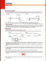
Thermal cutoff(*) should be mounted such that the temperature gradient is equal throughout
the thermal cutoff.
lf lead B of the SF-type, which is caulked to the metal case, is mounted in such a way that it only conducts
heat to the metal case, the temperature around the thermal pellet would always be higher than other parts
in the metal case. This could lead to the thermal cutoff opening prematurely. Hence, it is recommended that
lead A, which is the resin-sealed side, be connected nearer to the heat source.
It should also be mentioned that similarly, if lead A is fixed in a location whereby the temperature it
is
exposed to is always lower than that of lead B, the thermal cutoff could also be prematurely triggered.
(")
except SFH-E series
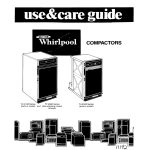
oDesigners of tfre end-bpplication should take into account the maximum surface temperature of the
thermal cutoff, as shown in Table 1, and avoid exceeding this level.
lf the body temperature of the thermal cutoff is exceeded on a regular basis, the thermal cutoff may start operating at
temperatures lower than the normal operating temperature. Malfunctions may also occur. ln case of using SM-type and
D6-type in DC rating, please kindly contact NEC SCHOTT Components Corporation.
Table
1
Note that the temperature listed in Table 1 refers to the surface temperature of the thermal cutoff,
and not the ambient temperature.
OThermal cutoffs have a limited life.
The thermal elements used are durable substances designed for long-time usage. However, the longevity of the thermal
cutoff depends on the conditions in which it is exposed to. This is particularly true if the thermal protection device is
frequently exposed to temperature very close to its operating temperature.
Hence, it is recommended that designers conduct a reliability test by fixing the thermal protection device onto the actual
end-application and simulating the expected operating conditions to assess the lifetime of the device.
oThe body temperature of the thermal cutoff increases as current passes through
it.
The body temperature of the thermal cutoff could rise to levels higher than the ambient temperature as the current passes
through the device. ln addition, the body temperature could also increase depending on a number of factors such as the
mounting method. Hence, it is recommended that designers measure the body temperature of thermal cutoff after
conducting a reliability test.
oUse the thermal cutoff with a voltage and current level lower than the rated level.
lf the thermal cutoff is used with a voltage or current level higher than the rated level, the contacts may be welded together
in the SF-type, causing the thermal cutoff to malfunction. ln the SM-type and D6-type, the body of the thermal cutoff may
rupture.
oDo not use the thermal cutoff in an atmospher out of lhe standard specifications such as in
environments exposed to sulfurous acid gas,nitrogen oxide gas,ammonia gas or conditions that
contain formic acid. lt is also not suitable for high humidity situations and submersion in a liquid.
The case of the thermal cutoff(-) is made with a copper alloy (brass). Hence, installing the thermal cutoff in such
conditions or similar, could deteriorate the sealing resin or lead to cracks in the case of the thermal cutoff due to corrosion.
The therm.al cutoff could thus operate at lower than operating temperatures or not activate even
if its operating
temperature is exceeded.
* except
SF-Y series, SM-type and D6-type
OThe thermal cutoff corresponds to industrial waste.
The thermal cutoff corresponds to industrial waste, and requires disposal according to governmental and provincial
regulations. The services of a licensed disposal contractor could also be engaged.
OThe thermal cutoff is a non-repairable device.
ln case of replacement, an equivalent thermal cutoff from the same manufacturer should be used. For general consumers
who are not aware ol the cautions associated with the thermal cutoff, they should be informed not to mount, remove or
replace the thermal cutoff through a note to this effect in the user's manual and other related materials.
24
Gautions
I
Lead wire process
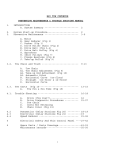
a When bending the lead wire, it is important not to apply excessive pressure to the root of the lead wire. Therefore, the lead
wire should be secured close to the case and bent (not twisted) at a distance 3 mm or more from the body of the fuse.
sF,/sM
Type
3 mm or
more
D6 Type
Secured
o The tensile strength applied to the lead wire should be SF-type: 49N or Iess and SM- and D6-types: 9.8N or less.
. The strength applied to the body of the thermal cutoff should be SF-type:98N or less, SM-type:49 N or less, and
D6-type:4.9N or less.
With regards to the SF-type, deformation of the case may change the location of the sliding contact during operation and
could lead to the thermal cutoff operating only at temperatures lower than the normal operating temperature range. The
thermal cutoff may also not operate even if the thermal cutoff's operating temperature is exceeded.
I
.
Mounting
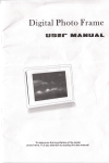
Thermal cutoff can be mounted by soldering, caulking or welding.
The connecting position at the lead of resin-sealed side should be 5 mm or more from the body of the thermal cutoff.
SF Type
SM Type
t-
t--l
I
D6 Type
5 mm or more
u,
I
l\
I \
5 mm or more
connecting
\
Posltron
5 mm or more
o lf soldering, note that the thermal cutoff
may function because of excessive solder temperature. To prevent such
malfunctions, for example, holding the lead near the case with a tool is effective for allowing the heat to escape and the
soldering should be done in short intervals.
Another effective method is to use a lower solder temperature and to solder at a location that is at a distance from the
case.
o lf caulking or welding, be careful to keep the
resistance value of the connecting section low. lf the connecting section has
a high resistance value, the passing current may generate an abnormally high temperature that will cause the thermal
cutoff to operate.
a After mounting the thermal cutoff, pe careful not to apply force that may pull, push or twist the lead wires.
o lf using a SF-type-thermal
cutoff, the lead on the resin-sealed side must not be allowed to touch the case. This would
cause the currentlo tlow ftorn the lead on the resin.sealed side to the opposite lead so that the thermal cutoff cannot open
the circuit.
a Note that the body of the SF-type is the same in potential as the circuit. Therefore, it must be electrieally isolated from the
other metallic part.
25
K Storage
.The body and lead A of the SF-type, and the leads of SM092A and SM092B are silver-plated. Therefore, these parts may
discolor because of sulfuration, making the marking of the body difficult to discriminate or negatively affecting the
solder-ability of the lead. To avoid this, the thermal cutoff should not be kept around materials (such as cardboard or
rubber, etc.) which generate sulfurous acid gas.
.When storage of thermal cutoff in cardboard boxes is required, the pack of thermal cutoffs should be double packed and
sealed in bags such as polyethylene.
K Recommendation
I
NEC SCHOTT recommend the following tests upon receipi and after mounting of the thermal cutoff,
as.it may have. undergone some mechanical load or therrnal influence during [ransportation or when
being mounted.
1.Appearance check
2. Resistance check (comparin$ before with after), or conductive check
3.X-ray inspection
4. Operation check for sampling
o
Be careful when mounting the thermal cutoff because external force, heat or a harmful atmosphere (containing excessive
humidity or sulfurous acid gas) may damage the characteristics of the thermal cutoff. lf applicable, it is recommended that
the general consumers, who are unaware of the usage cautions for thermal cutoff, be informed not to mount, remove, or
replace the thermal cutoff through a note to this effect in the user's manual and other related material.
For any clarifications or more information about these cautions, please kindly contact NEC SCHOTT Components
Corporation.
The values contained in this document were obtained under the testing conditions conducted by NEC SCHOTT. These are
not guaranteed and are for reference only.
.The information herein is based on the documents as of July 201 1, and is subject to change without notice. Therefore
it is recommended to refer to latest individual information such as drawing for mass production designing.
.lt is prohibited to reprint or copy the contents herein without written agreement of NEC SCHOTT
Components
Corporation.
olf problems relevant to the industrial property right of third parties occur by using the products, we would not assume
any responsibility lor matters other than ones directly related to the manufacturing process, which please note.
oAlthough we have been making continuous efforts to improve the quality and reliability of our products, the possibility
of defects cannot be eliminated entirely. Therefore when using our electronic component products, please make sure
to consider safety measures in its design, such as redundancy, fire containment and malfunction prevention against
physical injuries, fire disasters and social damages in consideration of the said defect occurrences. l
Our products are classified into 2 quality grades: "Standard" and "Special". The recommended applications 9f the
products according to its quality level are indicated below. If you intend to use our products for applications other than
"Standard" level, pleasemake sure to consutt with our sales representative in advance.
"standard"
Computers, office equipment, communication equipment, measuring equipment, audio & visual equipment, home
electric appliances, machine tools, personal electric equipment and industrial robots. etc.
"Special"
Transportation equipment (automobiles, trains, ships and others), aircrafts, aerospace equipment, medical equipment
for life support. etc.
26