1
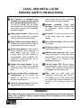
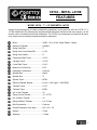
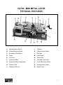
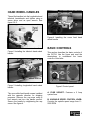
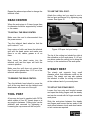
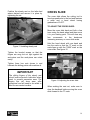
CX704 7” x 12” MINI METAL LATHE User Manual TABLE OF CONTENTS General Safety Instructions................................................................................................. 3 Specific Safety Instructions ................................................................................................. 4 Features .............................................................................................................................. 5 Physical Features................................................................................................................ 6 Set-Up ................................................................................................................................. 7 Un-Packing.......................................................................................................................... 7 Proper Grounding................................................................................................................ 8 Hand Wheel Handles .......................................................................................................... 9 Basic Controls ..................................................................................................................... 9 Test Run.............................................................................................................................. 10 Chuck Jaws Replacement................................................................................................... 11 Installing / Removing Chuck or Faceplate........................................................................... 11 Tailstock .............................................................................................................................. 12 Tailstock Positioning ........................................................................................................... 12 Dead Center........................................................................................................................ 13 Tool Post ............................................................................................................................. 13 Steady Rest......................................................................................................................... 13 Cross Slide.......................................................................................................................... 14 Compound Slide.................................................................................................................. 15 Carriage .............................................................................................................................. 15 Changing Gears .................................................................................................................. 16 Threads Cutting................................................................................................................... 17 Maintenance........................................................................................................................ 17 Cleaning .............................................................................................................................. 17 Lubrication........................................................................................................................... 18 Gibs Adjustment.................................................................................................................. 18 Motor Brushes Replacement............................................................................................... 19 Headstock & Tailstock Alignment........................................................................................ 19 Wiring Diagram ................................................................................................................... 21 Parts Breakdown................................................................................................................. 22 Parts List ............................................................................................................................. 23 Warranty.............................................................................................................................. 27 2 GENERAL SAFETY INSTRUCTIONS FOR MACHINES Extreme caution should be used when operating all power tools. Know your power tool, be familiar with its operation, read through the user manual and practice safe usage procedures at all times. ALWAYS read and understand the user manual before operating the machine. CONNECT your machine ONLY to the matched and specific power source. ALWAYS wear safety glasses respirators, hearing protection and safety shoes, when operating your machine. DO NOT wear loose clothing or jewelry when operating your machine. A SAFE ENVIRONMENT is important. Keep the area free of dust, dirt and other debris in the immediate vicinity of your machine. BE ALERT! DO NOT use prescription or other drugs that may affect your ability or judgment to safely operate your machine. DISCONNECT the power source when changing drill bits, hollow chisels, router bits, shaper heads, blades, knives, or making other adjustments or repairs. NEVER leave a tool unattended while it is in operation. NEVER reach over the machine when the tool is in operation. ALWAYS keep blades, knives and bits sharpened and properly aligned. ALL OPERATIONS MUST BE performed with the guards in place to ensure safety. ALWAYS use push sticks and feather boards to safely feed your work through the machine and clamp the work-piece (when necessary) to prevent the workpiece from any unexpected movement. ALWAYS make sure that any tools used for adjustments are removed before operating the machine. ALWAYS keep the bystanders safely away while the machine is in operation. NEVER attempt to remove jammed cutoff pieces until the saw blade has come to a full stop. 3 CX704 - MINI METAL LATHE SPECIFIC SAFETY INSTRUCTIONS This machine is designed and intended for use by properly trained and experienced personnel only. If you are not familiar with the proper use of lathes, do not use this machine until proper training and knowledge has been obtained. broken parts, and any other conditions that may effect the tools operation. Keep guards in place. Safety guards must be kept in place and in working order all the times to ensure safety. Be careful. Do not put your hand close to the cutter while the machine is running. Keep children and visitors away. All children and visitors should be kept at a safe distance from the work area. Never leave the lathe unattended while it is running. Wear proper apparel. Loose clothing, gloves, neckties, rings, bracelets, or other jewelry may get caught in moving parts. Non-slip footwear is recommended. Wear protective hair covering to contain long hair. Do not wear any type of gloves. Remove adjusting keys and wrenches. Remove all the tools used for adjustment before turning the machine on. Do not over-reach. Keep proper footing and balance at all times. Maintain tools with care. Keep tools sharp and clean for best and safest performance. Follow instructions given in the manual for lubrication and replacing accessories. Always use safety glasses. For the safety of your eyes, safety glasses should be used while operating the lathe. Turn the power OFF. Before making any adjustments, make sure the switch is in the “OFF” position and the cord is un-plugged from the power outlet. Do not use the lathe in dangerous environments. Do no expose the machine to rain. Do not use the machine in wet locations. Make sure you have read and understood all the safety instructions in the manual and you are familiar with your metal lathe, before operating it. If you fail to do so, serious injury could occur. Check for damaged parts. Check for proper alignment of moving parts, WARNING! The safety instructions given above can not be complete because the environment in every shop is different. Always consider safety first as it applies to your individual working conditions. 4 CX704 – METAL LATHE FEATURES MODEL CX704 – 7” x 12” MINI METAL LATHE As part of the growing line of Craftex metalworking equipment, we are proud to offer the CX704 a 7” x 12” Mini Metal Lathe. By following the instructions and procedures laid out in this user manual, you will receive years of excellent service and satisfaction. The CX704 is a professional tool and like all power tools, proper care and safety procedures should be adhered to. Motor....................................................300W, 110 V, 60 Hz, Single Phase, 3 Amps Number Of Speeds ..............................Variable Swing Over Bed ...................................7" Swing Over Cross Slide (RD)...............2-1/8" Swing Over Saddle ..............................5" Compound Slide Travel .......................2-3/4" Carriage Travel ....................................10-1/2" Cross Slide Travel................................2-3/4" Maximum Tool Bit Size ........................5/16" Headstock Construction .......................Cast Iron Spindle Bore ........................................20mm Spindle Size .........................................3" Spindle Taper.......................................MT#3 Range of Spindle Speeds ....................Low 0 - 1100, High 0 - 2500 RPM Tailstock Travel ....................................2-1/2" Tailstock Taper ....................................MT#2 No. of Inch Threads .............................18 Range of Inch Threads ........................12 - 52 TPI No. of Metric Threads ..........................10 Range of Metric Threads .....................0.4 - 2.0mm Bed Construction .................................Cast Iron Overall Dimension of the lathe .............28" x 12" x 12" Weight..................................................75 lbs Warranty ..............................................3 Years 5 CX704 - MINI METAL LATHE PHYSICAL FEATURES A. Variable Speed Switch J. Tailstock B. Forward/Reverse Switch K. Tailstock Hand Wheel C. Emergency Stop Button L. Bed Way D. Chuck M. Lead Screw E. Tool Post N. Thread Dial F. Compound Slide O. Automatic Feed Lever G. Compound Slide Hand Wheel P. Cross Slide Hand Wheel H. Tailstock Quill Q. Carriage Hand Wheel I. Tailstock Quill Lock R. Gears Cover 6 SETUP UNPACKING Before setting up your machine you must read and understand the instructions given in this manual. To ensure safe transportation this machine is properly packaged and shipped completely in crates. When unpacking, carefully inspect the crates and ensure that nothing has been damaged during transit. Open the crates and check that the machine and the parts are in good condition. The unpainted surfaces of this lathe are coated with a rust preventive waxy oil and you will want to remove this before starting assembly. Use a solvent cleaner that will not damage painted surfaces. WARNING! CX704 is a heavy machine, do not overexert yourself. Use fork truck or other mechanical devices or get the help of a friend for safe moving method. If you can not find any part, check if the part is already installed on the machine. Some of the parts come assembled with the machine because of shipping purposes. When setting up your machine, you will want to find an ideal spot where your metal lathe will most likely be positioned most of the time. 7 PROPER GROUNDING Grounding provides a path of least resistance for electric current to reduce the risk of electric shock. CX704 is for use on a normal 110 volt circuit. Make sure that the machine is connected to an outlet having the same configuration as the plug. If an adaptor plug is used, it must be attached to the metal screw of the receptacle. To prevent electrical hazards, have a qualified electrician ensure that the line is properly wired. The lathe should be wired with a plug having 3 prongs to fit a 3 prong grounded receptacle as shown in figure-1. Do not remove the grounding prong to fit it into a 2 pronged outlet. WARNING! Improper connection of the equipmentgrounding conductor can result in a risk of electric shock. Check with a qualified electrician if you are in doubt as to whether the outlet is properly grounded. It is strongly recommended not to use extension cords with your CX704. Always try to position your machine close to the power source so that you do not need to use extension cords. In case if you really find it necessary to use an extension cord, make sure the extension cord does not exceed 50-feet in length and the cord is 14-gauge to prevent motor damage. Figure-1 110-Volts outlet for CX704 8 HAND WHEEL HANDLES Thread the handles into the longitudinal and tailstock handwheels and tighten using a screw driver and an open wrench. See figure-2 & 3. Figure-4 Installing the cross feed hand wheel handle BASIC CONTROLS Figure-2 Installing the tailstock hand wheel handle Figure-3 Installing longitudinal hand wheel handle The cross slide feed handle comes installed with the opposite direction for shipping purposes. Remove the cap srew using a hex wrench and turn the handle around. Secure the handle by retightening the cap screw. See figure-4. This section describes the basic controls of the CX704. Use the figure and read the descriptions to understand the basic controls of this lathe. Figure-5 Control panel A. FUSE SOCKET: Features a 5 Amp system fuse. B. VARIABLE SPEED CONTROL KNOB: Controls the spindle speed range from 0 2500 RPM. 9 C. FORWARD/REVERSE SWITCH: Changes the direction of rotation of spindle from clockwise to neutral and counterclockwise. D. EMERGENCY STOP BUTTON: Shuts down the power to the motor when pushed in. TEST RUN Once you have assembled your machine completely, it is then time for a test run to make sure that the machine works properly and is ready for operation. WARNING! Before starting the lathe, make sure that you have read and understood the manual and you are familiar with the functions and safety features on this machine. Failure to do so may cause serious personal injury or damage to the lathe. Figure-6 Rear controls E. LEAD SCREW REVERSE LEVER: Changes the direction of rotation of leadscrew for power feed or threading operations. F. HIGH/LOW RANGE CONTROL LEVER: Changes the spindle speed range from high (0 - 2500 RPM) to low (0 - 1100 RPM). TO TEST RUN THE CX704: Remove all the tools and objects used for assembling the machine. Walk around the machine, ensure all nuts, bolts, and screws are tightened and the machine is properly assembled. Locate the High/Low range control lever at the back of the lathe and set it to Low range. Set the Forward/Reverse button to Forward position. Connect the cord to the power source and lift the Emergency Stop button. Rotate the Variable Speed Control Knob slowly and you will hear a click as the power is turned ON. The spindle speed will increase as you turn the knob and the lathe should run with little or no vibration. During the test run if you hear any unusual noise coming from the lathe or the spindle does not rotate smoothly, immediately shut 10 off the machine and investigate to find out the problem. If the lathe is running smoothly, let it run for a few minutes and gradually increase the RPM using the variable speed control knob until it reaches the maximum RPM of 2500. Allow the lathe to run for a few minutes and stop it by pressing the Emergency Stop Button. WARNING! DO NOT change the direction of rotation of leadscrew while the lathe is running. Failure to do so could result damage to the lathe. CHUCK JAWS REPLACMENT Replacing the chuck jaws is very simple on CX704. You just have to pay attention to the sequence in which the jaws are loaded into the chuck. TO REPLACE THE JAWS: Insert the jaw in to the slot#1 and turn the chuck key clockwise untill the jaw is engaged with the thread. Repeat the same step with jaw#2 and then jaw#3. Make sure the jaws are installed in sequence. WARNING! Make sure not to over-tighten the jaws. This will damage the jaws. For doing accentric work, do not install the jaws into the chuck incorrectly. Always use a 4 jaw chuck for this job. INSTALLING / REMOVING CHUCK OR FACEPLATE The chuck is mounted directly to the spindle nose plate using studs and hex nuts. TO REMOVE THE CHUCK / FACEPLATE: Make sure the cord is disconnected from the power source. Hold the chuck with one hand and remove the three hex nuts securing the chuck to the to the spindle nose plate using a wrench. Make sure the cord is disconnected from the power source. Remove all the jaws on the chuck by turning the chuck key counter clockwise. Clean the jaws and the slot in the chuck with a piece of cloth and make sure there is no debris. The jaws are numbered as A, B, C or 1,2,3 and the numbers are in the slot on the chuck. Figure-7 Removing the faceplate 11 Tap the chuck / faceplate with a rubber mallet (if needed) and pull it out. TAILSTOCK POSITIONING TO ADJUST THE LONGITUDINALLY: TO INSTALL THE CHUCK / FACEPLATE: Remove the studs from the old faceplate / chuck you just removed and thread them into the faceplate / chuck you want to install. Make sure the cord is disconnected from the power source. Loosen the tailstock lock nut securing the tailstock on the lathe bed with a proper size wrench. See figure-9. When threading the studs into the new faceplate/chuck, make sure the studs are protruding 1/2" from the check surface. Align the studs witht holes on the spindle nose and secure the faceplate / chuck using the hex nuts removed. TAILSTOCK The tailstock slides along the bed way and can be locked in position by tightening the hex nut on its base. The tailstock features a hand wheel which moves the MT2 tailstock quill in or out and a lock lever to secure the quill in position. The offset screw on the tailstock helps maintain tailstock position during tailstock offset adjustment. See figure-8. Figure-9 Loosening the tailstock lock nut TO OFFSET THE TAILSTOCK: Loosen the tailstock lock nut shown in figure-9 and remove the tailstock. Loosen the tailstock offset cap screw shown in figure-8 a few turns and slide the tailstock back onto the bed. Adjust the tailstock to the desired offset and tighten the setscrew to secure the tailstock in position. Remove the tailstock from the lathe bed and tighten the offset cap screw. Slide the tailstock back onto the lathe bed and tighten the tailstock lock nut to secure the tailstock in position. Figure-8 Tailstock controls 12 Repeat the above steps often to change the tailstock offset. DEAD CENTER TO USE THE TOOL POST: Attach the cutting tool you want to use to the tool post and secure it by tightening cap screws. See figure-10. When the work-piece is 3 times longer than its diameter should be supported by a dead or live center. TO INSTALL THE DEAD CENTER: Make sure the cord is disconnected from the power source. Turn the tailstock hand wheel so that the quill is about 1" out. Use a piece of cloth and clean the tailstock quill and the dead center and make sure there is no dirt, debris, grease or oil on them. Now, insert the dead center into the tailstock quill and the taper will hold the center in position. Make sure the quill does not extend less than 0 and not greater than 1-1/2" out of the tailstock while operation. TO REMOVE THE DEAD CENTER: Turn the tailstock hand wheel to move the quill all the way back into the tailstock and dead center will come out of the quill. TOOL POST A four-way tool post is supplied with CX704 which rotates to four 90° preset stops or at any angle in between. Cutting tools can be attached and removed by tightening or loosening the cap screws on the tool post. Figure-10 Proper tool post setup The tip of the cutting tool should be right at the centerline on the work-piece. If it is not, use shims under the cutting tool to bring the tool up, to the centerline of the work-piece. STEADY REST The steady rest supports long, small diameter stock that otherwise could not be turned. The steady rest can also replace the tailstock to allow for cutting tool acces at the outboard end of your work-piece. TO SET-UP THE STEADY REST: Loosen the hex nuts and knurled screws and open the sliding fingers until the steady rest can be moved with its finger around the work-piece. Slide the work-piece between the steady rest fingers and secure the two ends of the work-piece between chuck and dead center or two centers as required. 13 Position the steady rest on the lathe bed where desired and secure it in place by tightening the nut. CROSS SLIDE The cross slide allows the cutting tool to travel perpendicular to the bed and features a scale and a hand wheel having graduations of 0.001". TO ADJUST THE CROSS SLIDE: Move the cross slide back and forth a few turns using the hand wheel and then move it to your starting point. This will clear any free movements in the leadscrew increasing accuracy on cross slide scale. Figure-11 Installing steady rest Hold the hand wheel with one hand and turn the scale so that the "0" mark on the scale lines up with the "0.000" mark on the cross slide. See figure-12. Tighten the knurled screws so that the fingers are snug but not tight against the work-piece and the work-piece can rotate easily. Tighten three hex nuts shown in and lubricate the sliding points with machine oil. IMPORTANT The sliding fingers of the steady rest should receive periodic lubrication when used, to prevent premature wear. The fingers tips will show wear after sometimes and will need to be milled or filed for new contact surface. Figure-12 Adjusting the cross slide When making the next cut, make sure to clear the backlash before moving the cross slide forward to the "0" mark. 14 COMPOUND SLIDE MANUAL MOVEMENT The compound slide rotates at a set angle and features a graduation scale of 0.001". The manual movement of the carriage can be controlled using the hand wheel shown in figure-14. TO ADJUST THE COMPOUND SLIDE: Loosen the bolts located on the compound slide shown in figure-13. Figure-14 Carriage hand wheel Figure-13 Loosening the bolts Rotating the hand wheel clockwise will move the carriage to the right and counterclockwise will move the carriage to the left on the lathe bed. Rotate the compound slide to the desired angle. AUTOMATIC MOVEMENT Tighten the bolt, loosened in the first step and make sure the compound slide does not move during tightening. Move the compound slide back and forth using the hand wheel and make sure the threads are engaging and there is no backlash, before you set the hand wheel scale to "0". CARRIAGE The carriage allows the cutting tool to move along the length of the lathe bed and the carriage movement can be controlled manually or automatically. To use the autamatic carriage movement, set the carriage to the desired starting point using the carriage hand wheel. Turn the variable speed control dial to the required RPM. Move the automatic feed lever down to engage the half-nut and activate the automatic feed feature. See figure-15. To deactivate the automatic feed feature, simply lift the the automatic feel lever up. Automatic feed feature also works when operating the lathe in reverse direction by changing the leadscrew after tunring the lathe OFF. 15 TO CHANGE THE GEARS: Make sure the cord is disconnected from the power source. Remove the gear cover to access the gears. Loosen the adjusted to disengage the gears from each other. Remove the gears and install the new gears according to the chart. See figure-17 & 18. Figure-15 Automatic feed lever Reinstall the adjuster and close the close the cover. WARNING! DO NOT change the direction of rotation of leadscrew while the lathe is running. Failure to do so could result damage to the lathe. CHANGING GEARS The gears on CX704 can be changed for a variety of different feed rates. Figure-17 Threads per inch chart Figure-16 Gears and adjuster Figure-18 Metric thread chart 16 THREADS CUTTING Several different threads can be cut using the proper combination of gears and settings. MAINTENANCE During the life of your machine, you will need to practice some regular maintenance to keep your lathe in peak performance condition. Set the compound slide to the proper angle required for the cut and align the tip of the cutting tool with the center of the workpiece. Check your machine daily for the following before use: Engage the thread dial with the leadscrew accodring to the chart (figure-19). * Loose mounting nuts and bolts * Worn or damaged cord * Damaged parts * Any other unsafe condition Install the gears according to the thread charts (figure-17 & 18) to get the required RPM for the job. Turn the spindle ON and select the RPM and make sure that the carriage is moving to the correct direction for cutting. CLEANING Treat the machine with care, keep it clean and grease and lubricate it regularly. Only through good care you can be sure that the working quality of the machine will remain constant. Oil, grease and cleaning agents are pollutants and must not be disposed off through the drains or in normal garbage. Dispose of those agents in accordance with current local environmental regulations. Cleaning rags impregnated with oil, grease and cleaning wool in a suitable closed vessel and disposed of in an environmentally sound way. Do not put them with normal garbage. During operation, the chips which fall onto the sliding surface should be cleaned in a timely fashion. Frequent inspections should be made to prevent chips from falling into the position between the carriage and bed way. Figure-19 Thread dial chart 17 Every day, after the operation, eliminate all the chips and clean different parts of the machine tool and apply machine tool oil to prevent from rusting. Good housekeeping practice should be followed on a daily basis keeping your lathe clean and well lubricated. GIBS ADJUSTMENT The cross slide and the compound slide gibs will need to be adjusted after sometimes. TO ADJUST THE CROSS-SLIDE AND COMPOUND SLIDE GIBS: Disconnect the cord from the power source. LUBRICATION Lubricate all slide ways of the lathe bed, compound slide and cross slide lightly before every use using 10-30W oil or similar. Loosen the lock nuts on the set screws shown in figure-20. The change gears, cross slide and compound slide lead screws must also be lightly lubricated with lithium based grease after every 6 months. Lubricate the transmission gears using lithium based grease every year. To lubricate the transmission gears, disconnect the cord from the power source and remove the front control panel, remove the ground wire from the headstock and spray grease in the hole. Rotate the chuck with your hand and shift the gears high to low. Figure-20 Cross slide and compound slide gibs adjustment screws Tighten or loosen the set screws as required and check the sliding movement of the cross slide / compound slide. It should move smoothly without any play. Once the set screws are adjusted, tighten the lock nuts to secure the set screws in position. 18 MOTOR BRUSHES REPLACEMENT TO REPLACE THE MOTOR BRUSHES: TO CHECK THE CENTERS ALIGNMENT: Center drill a 6" piece of bar stock on one end and position it between the headstock and tailstock as shown in figure-22. Make sure the cord is disconnected from the power source. Remove the front and rear caps shown in figure-21. Figure-22 checking headstock and tailstock alignment Turn approximately 0.010" off diameter. Figure-21 Front motor brush cap Measure the stock with a micrometer. If the stock is thicker at the tailstock end, the tailstock needs to be moved towards you by half the amount of taper. See figure-23. Replace the motor brushes with new ones and tighten the caps. HEADSTOCK & TAILSTOCK ALIGNMENT The headstock and tailstock alignment has been adjusted properly in the factory before the machine is shipped to you. However, after lengthy operation, the headstock and tailstock may be out of alignment. Figure-23 Stock thicker at the tailstock end If the stock is thinner at the tailstock end, the tailstock needs to be moved away from you half the amount of taper. See figure-24. 19 Figure-24 Stock thinner at the tailstock end TO MOVE THE TAILSTOCK: Make sure the switch is in the OFF position and the cord is disconnected from the power outlet. Adjust the tailstock offset half the amount by turning the offset screw. Turn another 0.010" off the stock and check for taper. Repeat this procedure until the tailstock is aligned with the headstock. 20 WIRING DIAGRAM FOR CX704 21 22 CX704 PARTS LIST PART# DESCRIPTION 33 Shifting Lever 1 QTY 34 Shifting Grip 1 1 Bed Way 1 35 Handle 1 2 3 Jaws Chuck 1 36 Fanning strip 1 3 Spindle 1 37 Compressive Spring 1 4 Screw M6 × 25 5 38 Indicator 1 6 Nut M6 10 39 Pinion 25T 1 7 Key M5 × 50 1 40 Support Screw 2 8 Key M4 × 8 2 41 Pinion 20T 1 9 Screw M5 × 12 6 42 Fixed Cover 1 10 Cover 2 43 Screw M6×20 5 11 Ball Bearing 2 45 Gear 45T 1 12 Spacer 2 46 Shaft 1 13 Head Stock Casting 1 47 Parallel Key 1 14 Gear 1 48 Gear shelf 1 15 Spacer 1 49 Screw M5 × 18 2 16 Spindle Gear 1 50 Pinion 20T 2 17 Nut M27×1.5 2 51 Washer 2 18 Screw M5×8 1 52 Screw M6 × 8 4 19 Steel Ball 2 53 Cover 1 20 Fixed Spring 3 54 Screw M5 × 45 2 21 Screw M6×6 1 55 Threads Cutting Chart 1 22 Retaining Ring M12 2 56 Screw M5 × 8 1 23 Ball Bearings 2 57 Washer M5 1 24 Gear 1 58 Bush W/Key 1 25 Parallel Key M4 × 45 1 59 Gear 80T 2 26 H/L Gear Shaft 1 60 Shaft 1 27 Pulley 1 61 Support Plate 1 28 Retaining Ring M10 1 62 Washer M8 2 29 Timing Belt 1 63 Nut M8 4 30 Shifting Fork 1 64 Shaft 1 31 Shifting Arm 1 67 Screw M6×16 2 32 Shifting Knob 1 69 Screw M4×10 3 23 70 Slide carriage box 1 106 Screw 71 Slope lock block 1 107 Gib Strip 1 72 Washer 3 108 Small carriage 1 73 Screw 2 109 Tool Rest fixed position 1 74 Key 2 110 Screw M6 × 25 9 75 Half nuts 2 111 Tool rest handle seat 1 76 Angle Block 1 112 Tool Rest 1 77 Screw M4×10 2 113 Stud M10 × 65 1 78 Groove plate opening 1 114 Lead screw 1 79 Handle seat 1 115 Indication position 1 80 Shaft 1 116 Screw M4 × 12 4 81 Feeding Gear (A) 11T/54T 1 119 Washer 1 82 Feeding Gear (B) 24T 1 120 Model Label 1 83 Screw 1 122 Indicator Table Label 1 84 Hand wheel assembly 2 123 Electric Cover 1 85 Hand shank 2 124 Plug 1 86A Three Ball Handle 1 125 Non-slip mat 4 86B Three Ball Handle 1 126 Chip Tray 1 87 Dial 2 127 Bracket 1 88 Positioning scale set 1 128 Key 2 89 Lead Screw 1 129 Lead Screw 1 90 Nut M5 5 131 Bracket 1 91 Screw M6×12 6 133 Screw M3×10 3 92 Slide Plate 2 134 Rack 1 93 Saddle 1 135 Clamp Plate 1 94 Gib Strip 1 136 Washer M10 1 95 Feeding Nut 1 137 Screw M5 × 16 1 96 Wheel aligner 1 138 Tailstock 1 97 Screw 2 139 Tailstock Lead Screw 1 98 Nut M4 8 140 Bearing flange 1 99 Screw M4 × 16 3 141 Screw M4 × 10 4 100 Cross Slide 1 142 Tailshaft 1 101 Screw M5 × 10 5 143 Center 1 102 Screw M4 × 8 2 144 Stud 105 Positioning plate 1 145 Pad M4 × 8 M8 × 20 M4 × 14 M8 × 40 3 1 1 24 146 Handle seat 1 188 Small spacer 1 148 Pulley 1 190 Spring 2 150 Motor 1 192 Washer 4 151 Motor Cover 1 193 Screw M8*55 2 152 Power cord Guard 1 194 Screw M4*38 1 153 Rear Splash Guard 1 195 Nut M4 1 154 H/L Label 1 196 Plate of tailstock 1 155 H/L Label 1 197 Screw M5*16 3 156 Warning Label 1 198 Base body cover 1 157 Gear 30T 1 199 Screw M5*25 1 158 Gear 35T 1 201 Chuck guard 1 159 Gear 40T 2 202 Shaft 1 160 Gear 45T 1 205 Screw M6 1 161 Gear 50T 1 206 Nut M6 2 162 Gear 55T 1 207 Compression Spring 1 163 Gear 57T 1 208 Washer 6 2 164 Gear 60T 1 209 Screw M3*4 4 165 Gear 65T 1 210 Switch Cover 1 166 Claw(cover) 1 212 Permanent seat 1 167 3-Jaw chuck Key 1 232 Screw M4×6 7 171 Clamp Block 1 235 Clamp Cover 1 172 Check Ring 1 236 Screw 1 173 Screw M5 ×8 4 237 Compression Spring 1 174 Protector 1 238 Screw M6×30 1 175 Screw M5 × 8 7 239 Washer 1 177 Screw M6 × 20 2 251 Cylinder Pin 1 178 Emergency Stop Switch 1 252 Turntable 1 179 1 253 Screw 3 180 Fuse Variable Speed Control Knob 254 Cover 1 181 Toggle Switch 1 255 Micro switch 1 182 PC Board 1 256 Dust sheet 1 184 Screw M5×10 1 257 Lead Screw Cover 1 185 Spring washer 5 1 258 266 Washer 4 3 187 Key 1 Washer 6 3 268 Screw 10 1 1 25 270 Support Pin 1 272 Protective Cover 1 303 Washer 1 318 Screw M5*20 1 319 Washer 1 320 Screw M6×10 4 321 Screw M6×16 4 322 Key 1 323 Screw M8×25 3 324 Screw M4×8 2 325 Flange 1 326 Screw 2 327 Screw M6×8 1 26 WARRANTY CRAFTEX 3 YEARS LIMITED WARRANTY Craftex warrants every product to be free from defects in materials and agrees to correct such defects where applicable. This warranty covers three years for parts and 90 days for labor (unless specified otherwise), to the original purchaser from the date of purchase but does not apply to malfunctions arising directly or indirectly from misuse, abuse, improper installation or assembly, negligence, accidents, repairs or alterations or lack of maintenance. Proof of purchase is necessary. All warranty claims are subject to inspection of such products or part thereof and Craftex reserves the right to inspect any returned item before a refund or replacement may be issued. This warranty shall not apply to consumable products such as blades, bits, belts, cutters, chisels, punches etceteras. Craftex shall in no event be liable for injuries, accidental or otherwise, death to persons or damage to property or for incidental contingent, special or consequential damages arising from the use of our products. RETURNS, REPAIRS AND REPLACEMENTS To return, repair, or replace a Craftex product, you must visit the appropriate Busy Bee Tools showroom or call 1800-461-BUSY. Craftex is a brand of equipment that is exclusive to Busy Bee Tools. For replacement parts directly from Busy Bee Tools, for this machine, please call 1-800-461-BUSY (2879), and have your credit card and part number handy. All returned merchandise will be subject to a minimum charge of 15% for re-stocking and handling with the following qualifications. Returns must be pre-authorized by us in writing. We do not accept collect shipments. Items returned for warranty purposes must be insured and shipped pre-paid to the nearest warehouse Returns must be accompanied with a copy of your original invoice as proof of purchase. Returns must be in an un-used condition and shipped in their original packaging a letter explaining your reason for the return. Incurred shipping and handling charges are not refundable. Busy Bee will repair or replace the item at our discretion and subject to our inspection. Repaired or replaced items will be returned to you pre-paid by our choice of carriers. Busy Bee reserves the right to refuse reimbursement or repairs or replacement if a third party without our prior authorization has carried out repairs to the item. Repairs made by Busy Bee are warranted for 30 days on parts and labour. Any unforeseen repair charges will be reported to you for acceptance prior to making the repairs. The Busy Bee Parts & Service Departments are fully equipped to do repairs on all products purchased from us with the exception of some products that require the return to their authorized repair depots. A Busy Bee representative will provide you with the necessary information to have this done. For faster service it is advisable to contact the nearest Busy Bee location for parts availability prior to bringing your product in for repairs. 27