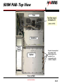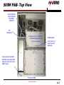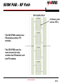
1
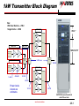
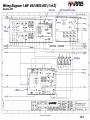
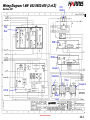
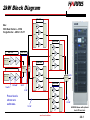
LPU Coaxial Switch
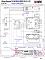
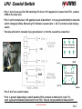
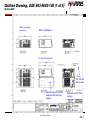
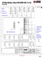
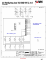
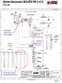
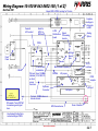
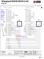
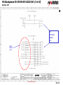
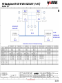
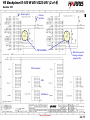
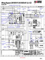
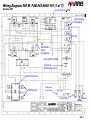
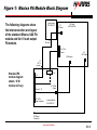
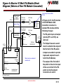
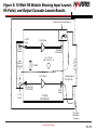
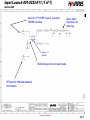
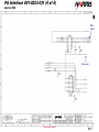
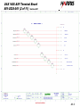
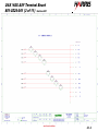
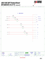
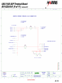
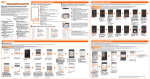
• Pins 1, 2 and 3 are used for LPU switching. Pin 2 has +12 V applied to it (comes from TCU, marked
COM on the relay box).
• Pins 1 and 3 normally have 12 V applied (via pin 2) but either 1 or 3 are grounded briefly to make the
switch change positions. Measuring 12 V between case and pins 1, 2 & 3 is normal except during a
switch.
• The relay will switch manually if you ground pins 1 or 3 to the case with a screwdriver
-
6
7
Top View. Looking down
from rear of transmitter.
+12
3
-
5
1
2
LPU B
Load
96
89
Same view as above.
Coax Connectors
GND
90
2
97
LPU A
Splitter
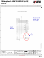
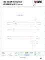
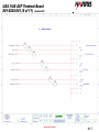
Pins 5, 6 & 7 are used for status.
Pin 6 is ground. Depending on switch position Pin 6 connects to either pin 5 or pin 7 to
send a ground indication (status) back to the TCU. The pin not grounded will measure 12V.
next level solutions
1-3.3