1
TX320 Transmitter
with a power cable that includes the fuse and a connector arrangement that
allows the transmitter to pull power directly from the battery when using the
CH200, CH100, PS100, or PS200 power supply.
With the potential for a 3000 mA current drain, the voltage drop along the
battery power leads must be considered. The battery power leads are both
wires that run from the battery to the power input connectors of the TX320. To
calculate the voltage drop along the power leads, we must know the resistance
of the wire and the length of the wire. Usually the resistance of the wire is
listed as ohms per 1000 feet. As an example, a 24 AWG wire used by
Campbell Scientific has a resistance of 23 ohms per 1000 feet. The length of
the wire is the distance the wire travels from the battery to the transmitter
multiplied by two. You must consider the current travels from the battery, to
the transmitter, and back to the battery.
The TX320 will operate with a battery voltage range from 10.8 V to 16 V. A
fully charged lead acid battery will have a voltage of about 12.5 V. If the
battery is fully charged, a 1.7 V drop along the battery leads will stop the
transmitter from transmitting. At 3 A, 1.7 V will be dropped with 0.566 ohms
of resistance. Using the 24 AWG wire with 23 ohms resistance per 1000 ft,
24 ft of wire (battery power leads 12 ft long) will prevent transmission. A
reliable system that will transmit without a perfect battery voltage will
minimize voltage drop along the battery power leads. To minimize voltage
drop, keep the battery power leads short. A five-foot power lead is a long
power lead. If you must have a longer lead, use heavy wire. For power leads
less than ten feet but more than five feet, use no smaller than 18 AWG.
7.3
Transmission Antenna
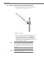
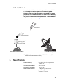
The TX320 transmission antenna is a right-hand circular polarized Yagi with
11 dBi gain. A bracket is included with the antenna for mounting to a mast or
pole. The antenna is directional and should be aimed at the spacecraft. Both
elevation and azimuth are unique to the location on the planet, and must be set.
A poorly aimed antenna will cause a drop in signal strength or possibly prevent
successful transmission.
The accuracy of the antenna aiming is not critical, but should be reasonably
good. As a guide, if the antenna is aimed 20 degrees off the spacecraft, the
received power will be half of a properly aimed antenna. Beyond 20 degrees,
the received power drops off very quickly.
7.4
GPS Antenna
7.4.1 How the GPS Signal is Acquired and Used
The GPS receiver will acquire a complete GPS fix at power up and once a day.
The TX320 transmitter will continue to operate normally for 28 days without a
GPS fix.
The GPS signal is used for two functions. To keep track of time, four satellites
are required. The second use of the GPS signal is to correct the oscillator
frequency. The GPS receiver will output a very accurate 1-second pulse. The
1-second pulse is used to correct oscillator drift caused by changes in
temperature and crystal aging.
17